EP3482431B1 - Batteriezelle sowie verfahren zum applizieren eines berstelements an einem gehäuseteil einer batteriezelle - Google Patents
Batteriezelle sowie verfahren zum applizieren eines berstelements an einem gehäuseteil einer batteriezelle Download PDFInfo
- Publication number
- EP3482431B1 EP3482431B1 EP17733823.3A EP17733823A EP3482431B1 EP 3482431 B1 EP3482431 B1 EP 3482431B1 EP 17733823 A EP17733823 A EP 17733823A EP 3482431 B1 EP3482431 B1 EP 3482431B1
- Authority
- EP
- European Patent Office
- Prior art keywords
- housing part
- hole
- battery cell
- rupture element
- structures
- Prior art date
- Legal status (The legal status is an assumption and is not a legal conclusion. Google has not performed a legal analysis and makes no representation as to the accuracy of the status listed.)
- Active
Links
Images
Classifications
-
- H—ELECTRICITY
- H01—ELECTRIC ELEMENTS
- H01M—PROCESSES OR MEANS, e.g. BATTERIES, FOR THE DIRECT CONVERSION OF CHEMICAL ENERGY INTO ELECTRICAL ENERGY
- H01M50/00—Constructional details or processes of manufacture of the non-active parts of electrochemical cells other than fuel cells, e.g. hybrid cells
- H01M50/10—Primary casings; Jackets or wrappings
- H01M50/147—Lids or covers
- H01M50/166—Lids or covers characterised by the methods of assembling casings with lids
- H01M50/169—Lids or covers characterised by the methods of assembling casings with lids by welding, brazing or soldering
-
- H—ELECTRICITY
- H01—ELECTRIC ELEMENTS
- H01M—PROCESSES OR MEANS, e.g. BATTERIES, FOR THE DIRECT CONVERSION OF CHEMICAL ENERGY INTO ELECTRICAL ENERGY
- H01M50/00—Constructional details or processes of manufacture of the non-active parts of electrochemical cells other than fuel cells, e.g. hybrid cells
- H01M50/30—Arrangements for facilitating escape of gases
- H01M50/342—Non-re-sealable arrangements
-
- H—ELECTRICITY
- H01—ELECTRIC ELEMENTS
- H01M—PROCESSES OR MEANS, e.g. BATTERIES, FOR THE DIRECT CONVERSION OF CHEMICAL ENERGY INTO ELECTRICAL ENERGY
- H01M50/00—Constructional details or processes of manufacture of the non-active parts of electrochemical cells other than fuel cells, e.g. hybrid cells
- H01M50/10—Primary casings; Jackets or wrappings
- H01M50/147—Lids or covers
- H01M50/155—Lids or covers characterised by the material
- H01M50/157—Inorganic material
- H01M50/159—Metals
-
- H—ELECTRICITY
- H01—ELECTRIC ELEMENTS
- H01M—PROCESSES OR MEANS, e.g. BATTERIES, FOR THE DIRECT CONVERSION OF CHEMICAL ENERGY INTO ELECTRICAL ENERGY
- H01M2220/00—Batteries for particular applications
- H01M2220/20—Batteries in motive systems, e.g. vehicle, ship, plane
-
- H—ELECTRICITY
- H01—ELECTRIC ELEMENTS
- H01M—PROCESSES OR MEANS, e.g. BATTERIES, FOR THE DIRECT CONVERSION OF CHEMICAL ENERGY INTO ELECTRICAL ENERGY
- H01M50/00—Constructional details or processes of manufacture of the non-active parts of electrochemical cells other than fuel cells, e.g. hybrid cells
- H01M50/10—Primary casings; Jackets or wrappings
- H01M50/116—Primary casings; Jackets or wrappings characterised by the material
- H01M50/117—Inorganic material
- H01M50/119—Metals
-
- Y—GENERAL TAGGING OF NEW TECHNOLOGICAL DEVELOPMENTS; GENERAL TAGGING OF CROSS-SECTIONAL TECHNOLOGIES SPANNING OVER SEVERAL SECTIONS OF THE IPC; TECHNICAL SUBJECTS COVERED BY FORMER USPC CROSS-REFERENCE ART COLLECTIONS [XRACs] AND DIGESTS
- Y02—TECHNOLOGIES OR APPLICATIONS FOR MITIGATION OR ADAPTATION AGAINST CLIMATE CHANGE
- Y02E—REDUCTION OF GREENHOUSE GAS [GHG] EMISSIONS, RELATED TO ENERGY GENERATION, TRANSMISSION OR DISTRIBUTION
- Y02E60/00—Enabling technologies; Technologies with a potential or indirect contribution to GHG emissions mitigation
- Y02E60/10—Energy storage using batteries
Definitions
- the present invention relates to a battery cell and a method for applying a bursting element to a housing part of a battery cell.
- High-voltage storage devices for electric or hybrid vehicles usually consist of several storage modules that are electrically connected to one another.
- Each of the memory modules in turn usually consists of a plurality of memory cells which are electrically connected to one another.
- the individual memory cells each have a housing, which, for. B. can have a cuboid shape or a cylindrical shape.
- the memory cells can heat up considerably during operation, which is usually also accompanied by a certain increase in pressure inside the memory cells. Although certain pressure increases inside the memory cells are tolerable, inadmissibly high pressure increases can occur in the memory cell due to chemical reactions occurring therein. If a predetermined pressure in the storage cells is exceeded, it must be ensured that the pressure can be reduced in a "controlled” or "defined manner".
- the battery cell housings are made of aluminum.
- a so-called “bursting membrane” is provided in a cover of the aluminum housing, which can also consist of aluminum.
- Such bursting membranes are Usually pre-embossed or laser-engraved and welded to the housing of the battery cell or to the cover of the battery cell using a complex micro-welding process. "Pre-embossed” or “laser-engraved” means that the bursting membrane is provided with one or more lines of weakness along which the bursting membrane tears when a predetermined pressure is exceeded and enables pressure to be released from inside the battery cells and into the environment.
- Such bursting membranes are usually welded to the battery housing or the battery cover from a side facing the cell interior of the battery cell.
- the DE 102010013027 A1 relates to a single cell for a battery, electrode foils of different polarity being arranged in a housing, the housing having an outflow opening at a predeterminable position which is closed by means of a membrane which is fastened to the housing from the outside.
- the JP H01220368 A relates to an explosion-proof device, wherein a sealing plate seals a gas vent hole of a valve body.
- the JP 2007220508 A relates to a battery that is equipped with a battery container and with a power generation element stored in the container. There is an opening on the battery container, which is sealed with a sealing element.
- the US 2011/027645 A1 relates to a method for forming a cell arrangement by an electrode body and an electrolyte in one external housing can be arranged with a through hole.
- a sealing film is welded to the external housing to temporarily seal the through hole.
- the object of the invention is to provide a housing part of a battery cell or for a battery cell in which a bursting element is fixed in a different, advantageous manner to a housing part of the battery cell, and to specify a corresponding method for applying a bursting element to a housing part of a battery cell.
- the starting point of the invention is a housing part of a battery cell or for a battery cell.
- the housing part can be, for example, a housing cover.
- housing cover can be understood to mean, for example, a part of the housing of a battery cell which, in relation to gravity, is arranged on an upper side of the battery cell or which forms an upper side or part of the upper side of the battery cell.
- the housing part not according to the invention consists e.g. made of a metal material, such as. B. aluminum or an aluminum alloy.
- the wall thickness of the housing part and / or the battery cell housing can, for. B. are in the range between 0.6 and 1 mm.
- the housing of the battery cell can e.g. B. have a cylindrical or prismatic, in particular cuboid shape.
- the above Housing part has an inside facing the inside of the battery cell and an outside facing an outside of the battery cell.
- a hole is provided in the housing part through which pressure can escape into the environment in the event of a fault in which an inadmissibly high pressure rise occurs inside the battery cell.
- the plate-like bursting element completely covers the hole provided in the housing part.
- An edge region of the bursting element is "normal", i. H. when the battery cell is in a perfect condition, is connected in a circumferential manner to an edge region of the housing part which extends around the hole, as a result of which the hole is closed in a fluid-tight manner by the bursting element.
- An essential feature of a housing part according to the invention of a battery cell or for a battery cell is that the plate-like bursting element is at least somewhat larger than the hole and is applied to the hole from the outside of the housing part.
- the present invention provides that when a predetermined internal battery cell pressure is exceeded (pressure inside the battery cell) Connection between the bursting element and the housing part fails or breaks or tears open and the bursting element arranged on the outside of the housing part and covering the hole provided in the housing part partially or completely detaches from the housing part and a reduction of an internal pressure prevailing inside the battery cell into the Environment.
- the housing part not according to the invention can e.g. be made of metal
- the bursting element not according to the invention e.g. can consist of a plastic material.
- the housing part consists of a plastic material and the bursting element consists of metal.
- the invention relates not only to the above-described housing part of a battery cell or for a battery cell, but also to a method for applying a bursting element to such a housing part of a battery cell, in particular to a housing part provided for closing a battery cell, such as, for. B. a housing cover element of a battery cell.
- the housing part not according to the invention can be made from a
- Metal material such as. B. aluminum or an aluminum alloy, and has an inside of the battery cell facing the inside and an outside of the battery cell facing outside.
- a hole is provided in the housing part through which pressure can escape into the environment in the event of a fault in which an inadmissibly high pressure rise occurs in the battery cell.
- a basic idea of the method according to the invention is that a plate-like bursting element is provided which is at least somewhat larger than the hole provided in the housing part.
- the plate-like bursting element is applied to the hole from the outside in such a way that it completely covers the hole.
- An edge region of the plate-like bursting element is connected all round to an edge region of the housing part which extends around the hole, in such a way that the plate-like bursting element closes the hole in a fluid-tight, in particular gas-tight, manner.
- Fluid-tight or gas-tight is to be understood in the sense of largely fluid-tight or largely gas-tight, a leak rate of up to 5 ⁇ 10 -6 (mbar * l) / s being regarded as gas-tight.
- the edge region of the plate-like bursting element is connected to the edge region of the housing part, which extends around the hole, without adhesive, e.g. B. by mechanical adhesion.
- Mechanical adhesion is understood to mean a form-fitting anchoring (in the micrometer or nanometer range) of an underside of the plate-like bursting element facing the housing part with an upper side of the housing part facing the bursting element.
- a form fit results (in the micrometer or nanometer range) by a positive interlocking engagement of the underside of the bursting element with the top of the housing part in the area of capillaries, pores or undercuts.
- a mechanical anchoring of the bursting element on the housing part is based on the penetration of material of the bursting element into such capillaries, pores or undercuts, the penetration taking place by flowing material of the bursting element during the joining of the bursting element and the "flowed material" of the bursting element after Joining the bursting element, d. H. after it in surface structures of the housing part, d. H. flowed into capillaries or pores or undercuts of the housing part, (re) solidified.
- a plate-like bursting element used.
- the bursting element and the housing part to which the bursting element is fixed can therefore be different materials, in particular a material combination of a metal (for example aluminum or aluminum alloy from which the housing part is made) and a non-metal, in particular one Plastic material from which the bursting element does not consist according to the invention act. It is important that the materials used for the housing part and the bursting element have a low water permeability.
- multilayer material composites such as a material composite with the layers of polypropylene-aluminum-polypropylene, for example in the manner of a film, are also not suitable as materials for the housing part and the bursting element.
- the surface structures e.g. capillaries, pores, undercuts or the like
- the housing part is made of plastic and the bursting membrane is made of metal.
- the rupture element is to roughen at least one edge area of the rupture element analogous to the description above, with plastic material of the housing part then beginning to flow when the rupture element is pressed on or pressed on and would flow into undercut areas of the surface structures of the rupture element. All of the method steps mentioned in the description (in the event that the housing part is made of plastic and the bursting membrane is made of metal) can therefore also be used “vice versa” according to the invention, ie the materials of the housing part and the bursting element mentioned in the description and the relevant method steps interchanged according to the invention.
- Laser processing can be used, for example, to produce groove-like structures and / or mushroom-like structures.
- Laser processing of the edge region of the hole makes it possible, in particular, to produce oxide connections of the material from which the housing part is made (for example in the case of aluminum, aluminum oxide structures).
- oxide connections of the material from which the housing part is made (for example in the case of aluminum, aluminum oxide structures).
- laser processing can produce oxide structures that are similar in shape to the shape of mushroom heads, which means that a large number of undercut areas can be produced that allow a rupture plate to be fixed well with a defined maximum or breaking strength.
- roughening can also be carried out using other suitable processing methods, e.g. by sandblasting.
- the edge region of the hole is machined in such a way that groove-like and / or mushroom-like structures or generally surface structures or roughnesses result, the dimensions (e.g. roughness depth or distance of individual roughness peaks) in the micrometer range or in the sub-micrometer range or in the nanometer range.
- material of the bursting plate begins to flow on the underside of the bursting plate and penetrates into undercut areas of the surface structures produced by the laser processing (e.g., groove-like and / or mushroom-like structures), which results in (in the micrometer or Nanometer range) results in a positive fit between the rupture plate and the housing part.
- the laser processing e.g., groove-like and / or mushroom-like structures
- the plate-like bursting element is joined by pressing or pressing the edge region of the plate-like bursting element onto the edge of the hole provided in the housing part.
- the bursting element in particular the edge of the bursting element and / or the housing part, in particular the edge region of the hole in the housing part, can be heated during the pressing on or pressing on, e.g. B. to a temperature in the range between 70 ° C and 130 ° C, in particular in the range between 80 ° C and 120 ° C.
- the heating supports a flow of the material of the rupture plate in undercut areas of the surface structures produced on the housing part by laser processing.
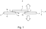
- Figure 1 shows a housing part 1 of a battery cell housing, not shown here.
- the housing part 1 can be, for example, a housing cover which, with respect to the direction g of gravity, closes a battery cell housing (not shown here) from above.
- the housing part 1 can not z. B. consist of aluminum or an aluminum alloy.
- a through hole 1a is provided in the housing part 1, which extends from an outside 1b of the housing part 1 to an inside of the inside 1c facing the battery cell (not shown here).
- the through hole 1 a is intended to allow pressure or gas to escape from the inside of the battery cell into the surroundings 2 in the event of a fault in which an inadmissibly high pressure rise occurs inside the battery cell.
- the through hole can have the shape of an elongated hole, which facilitates the filling of an electrolyte liquid into the interior of the battery cell.
- the through hole 1a of the housing part 1 has a peripheral edge 3 which extends around the through hole 1a.
- This edge 3 which forms part of the outside 1b of the housing part 1, is roughened.
- the roughening of the edge area 3 can, for. B. done by irradiation with a laser. This allows targeted surface structures such. B. Capillaries, pores or the like, which have undercuts, are produced.
- irradiation with a laser not shown here, groove-like structures can be produced in particular in the edge region 3.
- oxide-like structures of the material from which the housing part 1 is made can also be produced. Tests have shown that in particular mushroom-like oxide structures can be formed which have numerous undercuts.
- a plate-like bursting element 4 which is not according to the invention made of a plastic material such as.
- the flow of the material of the bursting element 4 can be supported if the bursting element 4 is heated at least in its edge region 4a and / or the housing part 1 at least in its edge region 3 during the pressing or pressing on of the bursting element 4, e.g. B. to a temperature in the range between 70 ° C and 130 ° C or over a temperature in the range between 80 ° C and 120 ° C.
Landscapes
- Chemical & Material Sciences (AREA)
- Chemical Kinetics & Catalysis (AREA)
- Electrochemistry (AREA)
- General Chemical & Material Sciences (AREA)
- Inorganic Chemistry (AREA)
- Gas Exhaust Devices For Batteries (AREA)
- Sealing Battery Cases Or Jackets (AREA)
Description
- Die vorliegende Erfindung betrifft eine Batteriezelle sowie ein Verfahren zum Applizieren eines Berstelements an einem Gehäuseteil einer Batteriezelle.
- Hochvoltspeicher von Elektro- oder Hybridfahrzeugen bestehen üblicherweise aus mehreren elektrisch miteinander verschalteten Speichermodulen. Jedes der Speichermodule wiederum besteht üblicherweise aus mehreren elektrisch miteinander verschalteten Speicherzellen. Die einzelnen Speicherzellen weisen jeweils ein Gehäuse auf, welches z. B. eine Quaderform oder eine Zylinderform haben kann.
- Während des Betriebs können sich die Speicherzellen beträchtlich erwärmen, was üblicherweise auch mit einem gewissen Druckanstieg im Inneren der Speicherzellen einhergeht. Wenngleich gewisse Druckanstiege im Inneren der Speicherzellen tolerierbar sind, kann es bei Fehlern in der Speicherzelle aufgrund darin ablaufender chemischer Reaktionen zu unzulässig hohen Druckanstiegen kommen. Bei Überschreiten eines vorgegebenen Drucks in den Speicherzellen muss sichergestellt sein, dass sich der Druck in "kontrollierter" bzw. "definierter Art und Weise" abbauen kann.
- Bei auf dem Markt befindlichen Speicherzellen, wie sie z. B. in Hochvoltspeichern von Elektrofahrzeugen der Marke BMW verbaut sind, sind die Batteriezellengehäuse aus Aluminium hergestellt. In einem Deckel des Aluminiumgehäuses ist eine so genannte "Berstmembran" vorgesehen, die ebenfalls aus Aluminium bestehen kann. Derartige Berstmembranen sind üblicherweise vorgeprägt oder lasergraviert und mit einem aufwändigen Mikroschweißverfahren an dem Gehäuse der Batteriezelle bzw. am Deckel der Batteriezelle angeschweißt. "Vorgeprägt" bzw. "lasergraviert" bedeutet, dass die Berstmembran mit einer oder mehreren Schwächungslinien versehen ist, entlang derer die Berstmembran bei Überschreiten eines vorgegeben Drucks reißt und einen Druckabbau aus dem Inneren der Batteriezellen und in die Umgebung ermöglicht.
- Derartige Berstmembranen sind üblicherweise von einer dem Zelleinneren der Batteriezelle zugewandten Seite her mit dem Batteriegehäuse bzw. dem Batteriedeckel verschweißt.
- Die
DE 102010013027 A1 betrifft eine Einzelzelle für eine Batterie, wobei in einem Gehäuse Elektrodenfolien unterschiedlicher Polarität angeordnet sind, wobei das Gehäuse an einer vorgebbaren Position eine Ausströmöffnung aufweist, die mittels einer Membran, die von außen an dem Gehäuse befestigt ist, verschlossen ist. - Die
JP H01220368 A - Die
JP 2007220508 A - Die
US 2011/027645 A1 betrifft ein Verfahren zum Bilden einer Zellenanordnung, indem ein Elektrodenkörper und ein Elektrolyt in einem externen Gehäuse mit einem Durchgangsloch angeordnet werden. Eine Siegelfolie wird mit dem externen Gehäuse verschweißt, um die Durchgangsbohrung vorübergehend abzudichten. - Dodiuk H et. al. "Preadhesion Laser Treatment of Aluminum Surfaces" im The Journal of Adhesion, June 1993, offenbaren einen Excimer-Laser, der zur Voradhäsionsbehandlung von Aluminiumlegierungen verwendet werden kann. Aufgabe der Erfindung ist es, ein Gehäuseteil einer Batteriezelle oder für eine Batteriezelle anzugeben, bei dem ein Berstelement in anderer, vorteilhafter Weise an einem Gehäuseteil der Batteriezelle fixiert ist, sowie ein entsprechendes Verfahren zum Applizieren eines Berstelements an einem Gehäuseteil einer Batteriezelle anzugeben.
- Diese Aufgabe wird durch die Merkmale des Patentanspruches 1 bzw. 2 gelöst. Vorteilhafte Ausgestaltungen und Weiterbildungen der Erfindung sind den Unteransprüchen zu entnehmen.
- Ausgangspunkt der Erfindung ist ein Gehäuseteil einer Batteriezelle oder für eine Batteriezelle. Bei dem Gehäuseteil kann es sich beispielsweise um einen Gehäusedeckel handeln. Unter dem Begriff "Gehäusedeckel" kann z.B. ein Teil des Gehäuses einer Batteriezelle verstanden werden, der, in Bezug auf die Schwerkraft, an einer Oberseite der Batteriezelle angeordnet ist bzw. bzw. der eine Oberseite oder einen Teil der Oberseite der Batteriezelle bildet.
- Der nicht erfindungsgemäße Gehäuseteil besteht z.B. aus einem Metallwerkstoff, wie z. B. Aluminium oder einer Aluminiumlegierung.
- Die Wandstärke des Gehäuseteils und/oder des Batteriezellengehäuses kann z. B. im Bereich zwischen 0,6 und 1mm liegen. Das Gehäuse der Batteriezelle kann z. B. eine zylindrische oder prismatische, insbesondere quaderartige Form haben.
- Der o.g. Gehäuseteil weist eine einem Innern der Batteriezelle zugewandte Innenseite und eine einem Äußeren der Batteriezelle zugewandte Außenseite auf. In dem Gehäuseteil ist ein Loch vorgesehen, über das in einem Fehlerfall, in dem es im Inneren der Batteriezelle zu einem unzulässig hohen Druckanstieg kommt, Druck in die Umgebung entweichen kann.
- Im Normalfall, d. h. wenn sich die Batteriezelle in einem einwandfreien Zustand befindet und der Druck im Inneren der Batteriezelle kleiner als ein vorgegebener zulässiger Höchstdruck ist, überdeckt das plättchenartige Berstelement das in dem Gehäuseteil vorgesehene Loch vollständig. Ein Randbereich des Berstelements ist im "Normalfall", d. h. wenn sich die Batteriezelle in einem einwandfreien Zustand befindet, umlaufend mit einem sich um das Loch herum erstreckenden Randbereich des Gehäuseteils verbunden, wodurch das Loch fluiddicht durch das Berstelement verschlossen ist.
- Ein wesentliches Merkmal eines erfindungsgemäßen Gehäusesteiles einer Batteriezelle oder für eine Batteriezelle besteht darin, dass das plättchenartige Berstelement zumindest etwas größer als das Loch ist und von der Außenseite des Gehäuseteils her auf das Loch aufgebracht ist. Im Unterschied zu der eingangs erwähnten mit mindestens einer Materialschwächung versehenen Berstmembran ist bei der vorliegenden Erfindung vorgesehen, dass bei Überschreiten eines vorgegebenen Batteriezelleninnendrucks (Druck im Inneren der Batteriezelle) eine Verbindung zwischen dem Berstelement und dem Gehäuseteil versagt bzw. aufbricht oder aufreißt und das an der Außenseite des Gehäuseteils angeordnete, das in dem Gehäuseteil vorgesehene Loch überdeckende Berstelement sich teilweise oder vollständig von dem Gehäuseteil löst und einen Abbau eines im Inneren der Batteriezelle herrschenden Innendrucks in die Umgebung ermöglicht.
- Wie oben bereits erwähnt kann das nicht erfindungsgemäße Gehäuseteil z.B. aus Metall sein, wobei das nicht erfindungsgemäße Berstelement z.B. aus einem Kunststoffmaterial bestehen kann. Erfindungsgemäß ist vorgesehen, dass das Gehäuseteil aus einem Kunststoffmaterial und das Berstelement aus Metall besteht.
- Gegenstand der Erfindung ist nicht nur das oben beschriebene Gehäuseteil einer Batteriezelle oder für eine Batteriezelle, sondern auch ein Verfahren zum Applizieren eines Berstelements an einem solchen Gehäuseteil einer Batteriezelle, insbesondere an einem zum Verschließen einer Batteriezelle vorgesehenen Gehäuseteil, wie z. B. einem Gehäusedeckelelement einer Batteriezelle. Das nicht erfindungsgemäße Gehäuseteil kann aus einem
- Metallwerkstoff, wie z. B. Aluminium oder einer Aluminiumlegierung, bestehen, und weist eine einem Innern der Batteriezelle zugewandte Innenseite und eine einem Äußeren der Batteriezelle zugewandte Außenseite auf. In dem Gehäuseteil ist ein Loch vorgesehen, über das in einem Fehlerfall, in dem es in der Batteriezelle zu einem unzulässig hohen Druckanstieg kommt, Druck in die Umgebung entweichen kann.
- Ein Grundgedanke des erfindungsgemäßen Verfahrens besteht darin, dass ein plättchenartiges Berstelement bereitgestellt wird, welches zumindest etwas größer als das in dem Gehäuseteil vorgesehene Loch ist. Das plättchenartige Berstelement wird so von einer Außenseite her auf das Loch aufgebracht, dass es das Loch vollständig überdeckt. Ein Randbereich des plättchenartigen Berstelements wird umlaufend mit einem sich um das Loch herum erstreckenden Randbereich des Gehäuseteils verbunden, derart, dass das plättchenartige Berstelement das Loch fluiddicht, insbesondere gasdicht, verschließt. Fluiddicht bzw. gasdicht ist im Sinne von weitegehend fluiddicht bzw. weitgehend gasdicht zu verstehen, wobei eine Leckrate von bis zu 5∗10-6 (mbar *l)/ s als gasdicht angesehen wird.
- Nach einer Weiterbildung der Erfindung erfolgt das Verbinden des Randbereichs des plättchenartigen Berstelements mit dem um sich das Loch herum erstreckenden Randbereich des Gehäuseteils klebstofffrei, z. B. durch mechanische Adhäsion. Unter "mechanischer Adhäsion" wird eine (im Mikrometer- oder Nanometerbereich) formschlüssige Verankerung einer dem Gehäuseteil zugewandten Unterseite des plättchenartigen Berstelements mit einer dem Berstelement zugewandten Oberseite des Gehäuseteils verstanden. Ein Formschluss ergibt sich (im Mikrometer- oder Nanometerbereich) durch formschlüssiges Ineinandergreifen der Unterseite des Berstelements mit der Oberseite des Gehäuseteils im Bereich von Kapillaren, Poren bzw. Hinterschneidungen. Eine mechanische Verankerung des Berstelements an dem Gehäuseteil beruht auf einem Eindringen von Material des Berstelements in derartige Kapillaren, Poren bzw. Hinterschneidungen, wobei das Eindringen durch Fließen von Material des Berstelements während des Fügens des Berstelements erfolgt und das "geflossene Material" des Berstelements nach dem Fügen des Berstelements, d. h. nach dem es in Oberflächenstrukturen des Gehäuseteils, d. h. in Kapillaren oder Poren oder Hinterschneidungen des Gehäuseteils geflossen ist, (wieder-)erstarrt.
- Nicht erfindungsgemäß wird ein aus einem Kunststoffmaterial, wie z. B. aus einem Polypropylenmaterial, bestehendes ein plättchenartiges Berstelement verwendet. Bei dem Berstelement und dem Gehäuseteil, an dem das Berstelement fixiert wird, kann es sich also um unterschiedliche Materialien, insbesondere um eine Materialkombination aus einem Metall (z.B. Aluminium oder Aluminiumlegierung aus dem bzw. der das Gehäuseteil besteht) und einem Nichtmetall, insbesondere einem Kunststoffmaterial, aus dem nicht erfindungsgemäß das Berstelement besteht, handeln. Wichtig ist, dass die für das Gehäuseteil und das Berstelement verwendeten Materialien eine geringe Wasserpermeabilität aufweisen. Als Materialien für das Gehäuseteil und das Berstelement kommen nicht erfindungsgemäß auch mehrschichtige Materialverbünde, wie z.B. ein Materialverbund mit den Schichten Polypropylen - Aluminium - Polypropylen in Betracht, z.B. in der Art einer Folie.
- Um die für eine mechanische Adhäsion bzw. für eine formschlüssige Verbindung der Unterseite des Berstelements mit der Oberseite des Gehäuseteils erforderlichen Oberflächenstrukturen (z. B. Kapillaren, Poren, Hinterschneidungen o. ä.) im Mikrometer- bzw. Nanometerbereich zu erzeugen, kann vorgesehen sein, dass auf einer Außenseite des Gehäuseteils eine Oberfläche des sich um das Loch herum erstreckenden Randbereichs vor dem Aufbringen des Berstelements mittels eines Lasers bearbeitet und dadurch aufgeraut wird.
- Wie oben bereits erwähnt, ist es erfindungsgemäß vorgesehen, dass das Gehäuseteil aus Kunststoff und die Berstmembran aus Metall ist. In diesem Fall ist das Berstelement, zumindest ein Randbereich des Berstelements analog der obigen Beschreibung aufzurauen, wobei beim dann beim Aufdrücken oder Aufpressen des Berstelements Kunststoffmaterial des Gehäuseteils zu fließen begänne und in Hinterschneidungsbereiche der Oberflächenstrukturen des Berstelements fließen würde. Alle in der Beschreibung erwähnten Verfahrensschritte können (für den Fall, dass das Gehäuseteil aus Kunststoff und die Berstmembran aus Metall ist) erfindungsgemäß also auch "umgekehrt" angewendet werden, d.h. die in der Beschreibung erwähnten Materialien des Gehäuseteils und des Berstelements sowie die betreffenden Verfahrensschritte sind erfindungsgemäß gegeneinander vertauscht. Durch das Laserbearbeiten bzw. Aufrauen werden (im Mikrometer- oder Nanometerbereich) die für eine formschlüssige Verbindung des Berstelements mit dem Gehäuseteil erforderlichen Oberflächenstrukturen hergestellt. Durch eine Laserbearbeitung lassen sich beispielsweise rillenartige Strukturen und/oder pilzkopfartige Strukturen erzeugen. Durch eine Laserbearbeitung des Randbereichs des Lochs lassen sich insbesondere Oxidverbindungen des Materials, aus dem das Gehäuseteil besteht (z.B. im Fall von Aluminium Aluminiumoxidstrukturen), herstellen. Versuche haben gezeigt, dass sich durch eine Laserbearbeitung Oxidstrukturen herstellen lassen, die hinsichtlich ihrer Form der Form von Pilzköpfen ähneln, wodurch sich eine Vielzahl von Hinterschnittbereichen herstellen lassen, die eine gute Fixierung eines Berstplättchens mit einer definierten Höchst- bzw. Bruchfestigkeit ermöglichen.
- Alternativ zu einer Laserbearbeitung kann das Aufrauen auch durch andere geeignete Bearbeitungsverfahren erfolgen, wie z.B. durch Sandstrahlen.
- Nach einer Weiterbildung der Erfindung wird der Randbereich des Lochs so bearbeitet, dass sich rillenartige und/oder pilzkopfartige Strukturen oder allgemein Oberflächenstrukturen bzw. Rauigkeiten ergeben, deren Abmessungen (z. B. Rautiefe bzw. Abstand einzelner Rauheitsberge) im Mikrometerbereich oder im Sub-Mikrometerbereich oder im Nanometerbereich liegen.
- Wie bereits erwähnt, beginnt beim Fügen des Berstplättchens an der Unterseite des Berstplättchens Material des Berstplättchens zu fließen und dringt in Hinterschneidungsbereiche der durch die Laserbearbeitung hergestellten Oberflächenstrukturen (z. B. rillenartigen und/oder pilzkopfartigen Strukturen) ein, wodurch sich (im Mikrometer- oder Nanometerbereich) ein Formschluss zwischen dem Berstplättchen und dem Gehäuseteil ergibt.
- Das Fügen des plättchenartigen Berstelements erfolgt durch Aufdrücken oder Aufpressen des Randbereichs des plättchenartigen Berstelements auf den Rand des in dem Gehäuseteil vorgesehenen Lochs.
- Alternativ oder ergänzend zu dem Aufdrücken oder Aufpressen des Berstelements kann das Berstelement, insbesondere der Rand des Berstelements und/oder das Gehäuseteil, insbesondere der Randbereich des Lochs des Gehäuseteils, während des Aufdrückens oder Aufpressens erwärmt werden, z. B. auf eine Temperatur, die Bereich zwischen 70° C und 130° C, insbesondere im Bereich zwischen 80°C und 120°C liegt. Durch das Erwärmen wird ein Fließen des Materials des Berstplättchens in Hinterschneidungsbereiche der auf dem Gehäuseteil durch die Laserbearbeitung hergestellten Oberflächenstrukturen unterstützt.
- Mit der Erfindung werden insbesondere folgende Vorteile erreicht:
- Im Vergleich zu den eingangs erwähnten auf- bzw. angeschweißten Aluminiumberstmembranen ergeben sich durch das erfindungsgemäße Verfahren Kostenvorteile.
- Ferner ergeben sich Vorteile hinsichtlich der Bauraumflexibilität. Der Rand des plättchenartigen Berstelements kann relativ nahe an einen Rand des Gehäuseteils heranreichen, selbst dann, wenn das Gehäuseteil in seinem Randbereich mit einem anderen Gehäuseteil der Batteriezelle verschweißt werden muss. Zwischen dem Rand des plättchenartigen Berstelements und einem Schweißbereich, in dem das Gehäuseteil mit einem anderen Gehäuseteil der Batteriezelle verschweißt wird, ist also nur ein vergleichsweise geringer Mindestabstand erforderlich.
- Ein weiterer wesentlicher Vorteil ist darin zu sehen, dass das Gehäuseteil (z. B. Gehäusedeckel) an dem das Berstelement befestigt wird, bereits mit einem anderen Gehäuseteil (z. B. Gehäusetopf) der Batteriezelle verschweißt werden kann und erst anschließend das Berstelement appliziert werden kann. Über das zunächst noch offene Loch des Gehäuseteils kann dann ein Elektrolyt in das Gehäuse der Batteriezelle eingefüllt werden. Nach dem Einfüllen des Elektrolyts durch das in dem Gehäuseteil vorgesehene Loch kann das Loch durch das oben beschriebene Applizieren des Berstelements fluiddicht verschlossen werden.
- Im Folgenden wird die Erfindung im Zusammenhang mit der Zeichnung näher erläutert. Die einzige
Figur 1 zeigt das Grundprinzip der Erfindung in stark schematisierter Darstellung. -
Figur 1 zeigt ein Gehäuseteil 1 eines hier nicht näher dargestellten Batteriezellengehäuses. Bei dem Gehäuseteil 1 kann es sich beispielsweise um einen Gehäusedeckel handeln, der, in Bezug auf die Richtung g der Schwerkraft, ein hier nicht näher dargestelltes Batteriezellengehäuse von oben her verschließt. Das Gehäuseteil 1 kann nicht erfindungsgemäß z. B. aus Aluminium oder aus einer Aluminiumlegierung bestehen. - In dem Gehäuseteil 1 ist ein Durchgangsloch 1a vorgesehen, welches sich von einer Außenseite 1b des Gehäuseteils 1 zu einem Inneren der hier nicht näher dargestellten Batteriezelle zugewandten Innenseite 1c erstreckt. Das Durchgangsloch 1a ist dazu vorgesehen, in einem Fehlerfall, in dem es im Inneren der Batteriezelle zu einem unzulässig hohen Druckanstieg kommt, Druck bzw. Gas aus dem Inneren der Batteriezelle in die Umgebung 2 entweichen zu lassen. Das Durchgangsloch kann die Form eines Langlochs haben, was das Einfüllen einer Elektrolytflüssigkeit in das Innere der Batteriezelle erleichtert.
- Das Durchgangsloch 1a des Gehäuseteils 1 weist einen umlaufenden Rand 3 auf, der sich um das Durchgangsloch 1a herum erstreckt. Dieser, einen Teil der Außenseite 1b des Gehäuseteils 1 bildende Rand 3 wird aufgeraut. Das Aufrauen des Randbereichs 3 kann z. B. durch Bestrahlen mit einem Laser erfolgen. Dadurch können gezielt Oberflächenstrukturen, wie z. B. Kapillaren, Poren o. ä., welche Hinterschneidungen aufweisen, hergestellt werden. Durch Bestrahlen mit einem hier nicht näher dargestellten Laser lassen sich in dem Randbereich 3 insbesondere rillenartige Strukturen erzeugen. Durch Bestrahlen mit einem Laser lassen sich ferner oxidartige Strukturen des Materials, aus dem das Gehäuseteil 1 besteht, erzeugen. Versuche haben gezeigt, dass sich dabei insbesondere pilzkopfartige Oxidstrukturen ausbilden lassen, welche zahlreiche Hinterschneidungen aufweisen.
- Nach dem Aufrauen das Randbereichs 3 des Gehäuseteils 1 wird ein plättchenartiges Berstelement 4, welches nicht erfindungsgemäß aus einem Kunststoffmaterial wie z.
- B. Polypropylen, bestehen kann, fluiddicht auf das Gehäuseteil 1 appliziert. Wie aus
Figur 1 ersichtlich ist, ist das plättchenartige Berstelement 4 etwas größer als das Durchgangsloch 1a, d. h. das plättchenartige Berstelement 4 überdeckt das Durchgangsloch 1a vollständig. Durch Aufdrücken bzw. Aufpressen des plättchenartigen Berstelements 4 auf das Gehäuseteil 1 beginnt an einer Unterseite 4a des Berstelements 4 Material des Berstelements 4 zu fließen. Material des Berstelements 4 fließt dabei insbesondere in Hinterschnittbereiche, die zuvor während des Aufrauprozesses erzeugt wurden. Dadurch ergibt sich im Mikrometer- bzw. Nanometerbereich ein sehr guter Formschluss zwischen dem Berstelement 4 und der Oberseite 1b des Gehäuseteiles 1 im Randbereich 3 des Gehäuseteils 1. - Das Fließen des Materials des Berstelements 4 lässt sich unterstützen, wenn das Berstelement 4 zumindest in seinem Randbereich 4a und/oder das Gehäuseteil 1 zumindest in seinem Randbereich 3 während des Aufdrückens bzw. Aufpressens der Berstelements 4 erwärmt wird, z. B. auf eine Temperatur im Bereich zwischen 70°C und 130°C bzw. über eine Temperatur im Bereich zwischen 80°C und 120°C.
Claims (14)
- Batteriezelle mit einem Gehäuseteil, wobei das Gehäuseteil (1)- eine einem Innern der Batteriezelle zugewandte Innenseite (1c) und eine einem Äußeren (2) der Batteriezelle zugewandte Außenseite (1b) aufweist, wobei- in dem Gehäuseteil (1) ein Loch (1a) vorgesehen ist, über das in einem Fehlerfall, in dem es im Inneren der Batteriezelle zu einem unzulässig hohen Druckanstieg kommt, Druck in die Umgebung entweichen kann, wobei- ein plättchenartiges Berstelement (4) vorgesehen ist, welches das Loch (1a) vollständig überdeckt, wobei ein Randbereich (4a) des Berstelements (4) umlaufend mit einem sich um das Loch (1a) herum erstreckenden Randbereich (3) des Gehäuseteils (1) verbunden ist, wodurch das Loch (1a) fluiddicht verschlossen ist, wobei- das plättchenartige Berstelement (4) zumindest etwas größer als das Loch (1a) ist und von der Außenseite (1b) her auf das Loch (1a) aufgebracht ist wobei vorgesehen ist,- dass bei Überschreiten eines vorgegebenen Drucks im Inneren der Batteriezelle eine Verbindung zwischen dem Berstelement (4) und dem Gehäuseteil (1) versagt und das Berstelement (4) sich teilweise oder vollständig von dem Gehäuseteil (1) löst,- das Gehäuseteil (1) aus einem Kunststoffmaterial und das plättchenartige Berstelement (4) aus einem Metall besteht.
- Verfahren zum Applizieren eines Berstelements (4) an einem Gehäuseteil (1) einer Batteriezelle, insbesondere an einem zum Verschließen einer Batteriezelle vorgesehenen Gehäuseteil, mit folgenden Schritten:Bereitstellen des Gehäuseteils (1), wobei das Gehäuseteil (1)∘ eine einem Innern der Batteriezelle zugewandte Innenseite (1c) und eine einem Äußeren (2) der Batteriezelle zugewandte Außenseite (1b) aufweist und∘ in dem Gehäuseteil (1) ein Loch (1a) vorgesehen ist, über das in einem Fehlerfall, in dem es in der Batteriezelle zu einem unzulässig hohen Druckanstieg kommt, Druck in die Umgebung entweichen kann, wobeiein plättchenartiges Berstelement (4) bereitgestellt wird, welches zumindest etwas größer als das Loch (1a) ist, wobei das plättchenartige Berstelement (4)- so von der Außenseite (1b) her auf das Loch (1a) aufgebracht wird, dass es das Loch (1a) vollständig überdeckt und- einen Randbereich (4a) des plättchenartigen Berstelements (4) umlaufend mit einem sich um das Loch (1a) herum erstreckenden Randbereich (3) des Gehäuseteils (1) verbunden wird, derart, dass das plättchenartige Berstelement (4) das Loch (1a) fluiddicht verschließt und- das Gehäusehäuseteil (1) aus einem Kunststoffmaterial und das plättchenartige Berstelement (4) aus einem Metall besteht.
- Verfahren nach Anspruch 2, dadurch gekennzeichnet, dass das Verbinden des Randbereichs (3) des plättchenartigen Berstelements (4) mit dem sich um das Loch (1a) herum erstreckenden Randbereich (3) des Gehäuseteiles (1) klebstofffrei erfolgt.
- Verfahren nach Anspruch 2 oder 3, dadurch gekennzeichnet, dass das Verbinden durch mechanische Adhäsion erfolgt.
- Verfahren nach einem der Ansprüche 2 bis 4, dadurch gekennzeichnet, dass das Gehäuseteil (1) aus einem Polypropylenmaterial verwendet wird.
- Verfahren nach einem der Ansprüche 2 bis 5, dadurch gekennzeichnet, dass das Berstelement (4) aus Aluminium oder aus einer Aluminiumlegierung besteht.
- Verfahren nach einem der Ansprüche 2 bis 6, dadurch gekennzeichnet, dass eine Oberfläche des sich um das Loch (1a) herum erstreckenden Randbereichs des Berstelements (4) vor dem Anbringen an das Gehäuseteil (1) aufgeraut wird, insbesondere durch eine Laserbearbeitung.
- Verfahren nach Anspruch 7, dadurch gekennzeichnet, dass durch das Bearbeiten mit einem Laser erfolgt und mit dem Laser in der Oberfläche des sich um das Loch (1a) herum erstreckenden Randbereichs des Berstelementes (4) Strukturen, insbesondere rillenartige Strukturen und/oder pilzkopfartige Strukturen, erzeugt werden.
- Verfahren nach Anspruch 8, dadurch gekennzeichnet, dass die Strukturen Abmessungen aufweisen, die im Mikrometerbereich oder im Sub-Mikrometerbereich oder im Nanometerbereich liegen.
- Verfahren nach einem der Ansprüche 8 oder 9, dadurch gekennzeichnet, dass die Strukturen zumindest teilweise mit Material des Gehäuseteils ausgefüllt sind.
- Verfahren nach einem der Ansprüche 8 bis 10, dadurch gekennzeichnet, dass die Strukturen derart hergestellt werden, dass sich in den Strukturen Hinterschnittbereiche ergeben, so dass sich zwischen dem in die Hinterschnittbereiche der Strukturen eindringenden Material des Gehäuseteils (1) und dem Berstelement (4) Formschlüsse ergeben.
- Verfahren nach einem der Ansprüche 8 bis 11, dadurch gekennzeichnet, dass die Strukturen, insbesondere die rillenartigen Strukturen und/oder pilzkopfartigen Strukturen teilweise oder überwiegend aus Oxiden des Werkstoffs des Gehäuseteils (1) gebildet sind, wobei die Oxide durch Bestrahlen mit einem Laser entstehen.
- Verfahren nach einem der Ansprüche 2 bis 12, dadurch gekennzeichnet, dass das Berstelement (4) auf das Gehäuseteil (1) aufgedrückt oder aufgepresst wird, wobei das Berstelement (4) und/oder das Gehäuseteil (1) während des Aufdrückens oder Aufpressens erwärmt wird.
- Verfahren nach Anspruch 13, dadurch gekennzeichnet, dass das Berstelement (4) und/oder das Gehäuseteil (1) während des Aufdrückens oder Aufpressens auf eine Temperatur erwärmt wird, die im Bereich zwischen 70°C und 130°C oder im Bereich zwischen 80°C und 120°C liegt.
Applications Claiming Priority (2)
| Application Number | Priority Date | Filing Date | Title |
|---|---|---|---|
| DE102016212450.1A DE102016212450A1 (de) | 2016-07-08 | 2016-07-08 | Gehäuseteil einer Batteriezelle oder für eine Batteriezelle sowie Verfahren zum Applizieren eines Berstelements an einem Gehäuseteil einer Batteriezelle |
| PCT/EP2017/065934 WO2018007216A1 (de) | 2016-07-08 | 2017-06-28 | Gehäuseteil einer batteriezelle oder für eine batteriezelle sowie verfahren zum applizieren eines berstelements an einem gehäuseteil einer batteriezelle |
Publications (2)
| Publication Number | Publication Date |
|---|---|
| EP3482431A1 EP3482431A1 (de) | 2019-05-15 |
| EP3482431B1 true EP3482431B1 (de) | 2020-03-04 |
Family
ID=59239913
Family Applications (1)
| Application Number | Title | Priority Date | Filing Date |
|---|---|---|---|
| EP17733823.3A Active EP3482431B1 (de) | 2016-07-08 | 2017-06-28 | Batteriezelle sowie verfahren zum applizieren eines berstelements an einem gehäuseteil einer batteriezelle |
Country Status (5)
| Country | Link |
|---|---|
| US (1) | US11056742B2 (de) |
| EP (1) | EP3482431B1 (de) |
| CN (1) | CN109075289B (de) |
| DE (1) | DE102016212450A1 (de) |
| WO (1) | WO2018007216A1 (de) |
Cited By (1)
| Publication number | Priority date | Publication date | Assignee | Title |
|---|---|---|---|---|
| DE102021116766A1 (de) | 2021-06-30 | 2023-01-05 | Bayerische Motoren Werke Aktiengesellschaft | Berstplättchen für eine Fahrzeugbatterie, Bersteinrichtung, Verfahren sowie Fahrzeugbatterie |
Families Citing this family (5)
| Publication number | Priority date | Publication date | Assignee | Title |
|---|---|---|---|---|
| DE102018206793A1 (de) * | 2018-05-03 | 2019-11-07 | Audi Ag | Deckel für ein Batteriegehäuse, Hochvoltbatterie für ein Kraftfahrzeug und Kraftfahrzeug |
| DE102018125002A1 (de) * | 2018-10-10 | 2020-04-16 | Bayerische Motoren Werke Aktiengesellschaft | Zellgehäuse für eine Batteriezelle einer Hochvoltbatterie eines Kraftfahrzeugs, Verfahren zum Herstellen eines Zellgehäuses, Batteriezelle, Hochvoltbatterie sowie Kraftfahrzeug |
| DE102018125842A1 (de) | 2018-10-18 | 2020-04-23 | Bayerische Motoren Werke Aktiengesellschaft | Zellgehäuse für eine Batteriezelle einer Hochvoltbatterie eines Kraftfahrzeugs, Batteriezelle, Hochvoltbatterie sowie Kraftfahrzeug |
| EP4096009B1 (de) * | 2021-02-09 | 2025-05-21 | Contemporary Amperex Technology (Hong Kong) Limited | Batterie, elektrische vorrichtung und verfahren und vorrichtung zur herstellung einer batterie |
| DE102021112231A1 (de) | 2021-05-11 | 2022-11-17 | Audi Aktiengesellschaft | Entgasungskanal, Batterieanordnung und Kraftfahrzeug |
Family Cites Families (7)
| Publication number | Priority date | Publication date | Assignee | Title |
|---|---|---|---|---|
| JPH01220368A (ja) * | 1988-02-29 | 1989-09-04 | Toshiba Battery Co Ltd | 有機電解液電池 |
| US6803142B2 (en) * | 2001-06-06 | 2004-10-12 | Toyota Jidosha Kabushiki Kaisha | Fuel cell |
| JP5456952B2 (ja) * | 2006-02-17 | 2014-04-02 | 株式会社Gsユアサ | 安全弁を備えた電池 |
| WO2008111356A1 (ja) * | 2007-03-09 | 2008-09-18 | Asahi Rubber Inc. | 過剰圧力開放弁及びそれを有する開放弁ユニット |
| JP4378662B2 (ja) * | 2008-01-31 | 2009-12-09 | トヨタ自動車株式会社 | 密閉型電池製造方法 |
| DE102010013027A1 (de) * | 2010-03-26 | 2011-09-29 | Daimler Ag | Einzelzelle für eine Batterie |
| DE102011078301A1 (de) * | 2011-06-29 | 2013-01-03 | Sb Limotive Co., Ltd. | Batteriezelle, Batterie, Batteriezellenmodul und Kraftfahrzeug |
-
2016
- 2016-07-08 DE DE102016212450.1A patent/DE102016212450A1/de not_active Withdrawn
-
2017
- 2017-06-28 EP EP17733823.3A patent/EP3482431B1/de active Active
- 2017-06-28 WO PCT/EP2017/065934 patent/WO2018007216A1/de not_active Ceased
- 2017-06-28 CN CN201780025945.0A patent/CN109075289B/zh active Active
-
2019
- 2019-01-07 US US16/240,873 patent/US11056742B2/en active Active
Non-Patent Citations (1)
| Title |
|---|
| None * |
Cited By (1)
| Publication number | Priority date | Publication date | Assignee | Title |
|---|---|---|---|---|
| DE102021116766A1 (de) | 2021-06-30 | 2023-01-05 | Bayerische Motoren Werke Aktiengesellschaft | Berstplättchen für eine Fahrzeugbatterie, Bersteinrichtung, Verfahren sowie Fahrzeugbatterie |
Also Published As
| Publication number | Publication date |
|---|---|
| EP3482431A1 (de) | 2019-05-15 |
| CN109075289A (zh) | 2018-12-21 |
| DE102016212450A1 (de) | 2018-01-11 |
| US11056742B2 (en) | 2021-07-06 |
| CN109075289B (zh) | 2021-12-10 |
| US20190140223A1 (en) | 2019-05-09 |
| WO2018007216A1 (de) | 2018-01-11 |
Similar Documents
| Publication | Publication Date | Title |
|---|---|---|
| EP3482431B1 (de) | Batteriezelle sowie verfahren zum applizieren eines berstelements an einem gehäuseteil einer batteriezelle | |
| EP0123201B1 (de) | Luftsauerstoffzelle | |
| DE112012005994B4 (de) | Abgedichtete Batterie und Verfahren zur Herstellung derselben | |
| DE102015110244B4 (de) | Batteriezellengehäuse und Verfahren zu dessen Herstellung | |
| EP3770989B1 (de) | Batteriegehäuse für eine fahrzeugbatterie | |
| WO2011042092A1 (de) | Elektrochemische zelle | |
| DE102019112432B4 (de) | Entgasungseinheit und Elektronikgehäuse, insbesondere Batteriegehäuse | |
| EP3443603B1 (de) | Druckentlastungsvorrichtung für ein batteriegehäuse, batteriegehäuse mit der druckentlastungsvorrichtung, batterie sowie verfahren zur druckentlastung einer batterie | |
| DE112013005284T5 (de) | Herstellungsverfahren einer abgedichteten Batterie, Abdichtelement für abgedichtete Batterie und abgedichtete Batterie | |
| DE102021132478A1 (de) | Zellgehäuseelement für eine Batteriezelle, Kraftfahrzeug und Verfahren zum Herstellen eines Zellgehäuseelements | |
| WO2014012715A1 (de) | Batteriezelle und verfahren zum verschliessen der batteriezelle | |
| WO2022263118A1 (de) | Entgasungseinheit und batteriegehäuse | |
| DE102021123031A1 (de) | Entgasungseinheit und Elektronikgehäuse, insbesondere Batteriegehäuse, sowie Herstellverfahren für eine Entgasungseinheit | |
| DE102021129752A1 (de) | Entgasungseinheit, Membran, Gehäuse, insbesondere Batteriegehäuse, und Herstellungsverfahren einer Membran | |
| EP3631923B1 (de) | Geschweisste druckentlastungsvorrichtung | |
| DE102013223361A1 (de) | Batteriezelle mit Sicherheitsventil und semipermeablem Verschlusselement | |
| WO2014072127A1 (de) | Batteriezelle mit gehäusedeckplatte mit vernieteter einfüllöffnung | |
| DE102014208062A1 (de) | Batteriesystem mit einer Mehrzahl von Batteriezellen und einer Entgasungseinrichtung | |
| DE102012212887A1 (de) | Akkumulator mit galvanischen Zellen | |
| DE102012224250A1 (de) | Batteriezelle mit Gehäusedeckplatte mit einer durch einen Gewindebolzen verschlossenen Einfüllöffnung | |
| DE102010063516A1 (de) | Gehäuse für eine Komponente eines Fahrzeugs in Sandwichbauweise | |
| DE102020216452A1 (de) | Pouchzelle | |
| DE3888199T2 (de) | Alkalimetallzelle. | |
| DE102013201160A1 (de) | Batteriezelle mit einem Ausdehnungs-Berst-Bereich | |
| EP2634457B1 (de) | Profilierte Dichtung für ein Gehäuse |
Legal Events
| Date | Code | Title | Description |
|---|---|---|---|
| STAA | Information on the status of an ep patent application or granted ep patent |
Free format text: STATUS: UNKNOWN |
|
| STAA | Information on the status of an ep patent application or granted ep patent |
Free format text: STATUS: THE INTERNATIONAL PUBLICATION HAS BEEN MADE |
|
| PUAI | Public reference made under article 153(3) epc to a published international application that has entered the european phase |
Free format text: ORIGINAL CODE: 0009012 |
|
| STAA | Information on the status of an ep patent application or granted ep patent |
Free format text: STATUS: REQUEST FOR EXAMINATION WAS MADE |
|
| 17P | Request for examination filed |
Effective date: 20181126 |
|
| AK | Designated contracting states |
Kind code of ref document: A1 Designated state(s): AL AT BE BG CH CY CZ DE DK EE ES FI FR GB GR HR HU IE IS IT LI LT LU LV MC MK MT NL NO PL PT RO RS SE SI SK SM TR |
|
| AX | Request for extension of the european patent |
Extension state: BA ME |
|
| DAV | Request for validation of the european patent (deleted) | ||
| DAX | Request for extension of the european patent (deleted) | ||
| GRAP | Despatch of communication of intention to grant a patent |
Free format text: ORIGINAL CODE: EPIDOSNIGR1 |
|
| STAA | Information on the status of an ep patent application or granted ep patent |
Free format text: STATUS: GRANT OF PATENT IS INTENDED |
|
| INTG | Intention to grant announced |
Effective date: 20191126 |
|
| GRAS | Grant fee paid |
Free format text: ORIGINAL CODE: EPIDOSNIGR3 |
|
| GRAA | (expected) grant |
Free format text: ORIGINAL CODE: 0009210 |
|
| STAA | Information on the status of an ep patent application or granted ep patent |
Free format text: STATUS: THE PATENT HAS BEEN GRANTED |
|
| AK | Designated contracting states |
Kind code of ref document: B1 Designated state(s): AL AT BE BG CH CY CZ DE DK EE ES FI FR GB GR HR HU IE IS IT LI LT LU LV MC MK MT NL NO PL PT RO RS SE SI SK SM TR |
|
| REG | Reference to a national code |
Ref country code: GB Ref legal event code: FG4D Free format text: NOT ENGLISH |
|
| REG | Reference to a national code |
Ref country code: CH Ref legal event code: EP |
|
| REG | Reference to a national code |
Ref country code: AT Ref legal event code: REF Ref document number: 1241403 Country of ref document: AT Kind code of ref document: T Effective date: 20200315 |
|
| REG | Reference to a national code |
Ref country code: DE Ref legal event code: R096 Ref document number: 502017004113 Country of ref document: DE |
|
| REG | Reference to a national code |
Ref country code: IE Ref legal event code: FG4D Free format text: LANGUAGE OF EP DOCUMENT: GERMAN |
|
| PG25 | Lapsed in a contracting state [announced via postgrant information from national office to epo] |
Ref country code: FI Free format text: LAPSE BECAUSE OF FAILURE TO SUBMIT A TRANSLATION OF THE DESCRIPTION OR TO PAY THE FEE WITHIN THE PRESCRIBED TIME-LIMIT Effective date: 20200304 Ref country code: NO Free format text: LAPSE BECAUSE OF FAILURE TO SUBMIT A TRANSLATION OF THE DESCRIPTION OR TO PAY THE FEE WITHIN THE PRESCRIBED TIME-LIMIT Effective date: 20200604 Ref country code: RS Free format text: LAPSE BECAUSE OF FAILURE TO SUBMIT A TRANSLATION OF THE DESCRIPTION OR TO PAY THE FEE WITHIN THE PRESCRIBED TIME-LIMIT Effective date: 20200304 |
|
| REG | Reference to a national code |
Ref country code: NL Ref legal event code: MP Effective date: 20200304 |
|
| PG25 | Lapsed in a contracting state [announced via postgrant information from national office to epo] |
Ref country code: GR Free format text: LAPSE BECAUSE OF FAILURE TO SUBMIT A TRANSLATION OF THE DESCRIPTION OR TO PAY THE FEE WITHIN THE PRESCRIBED TIME-LIMIT Effective date: 20200605 Ref country code: BG Free format text: LAPSE BECAUSE OF FAILURE TO SUBMIT A TRANSLATION OF THE DESCRIPTION OR TO PAY THE FEE WITHIN THE PRESCRIBED TIME-LIMIT Effective date: 20200604 Ref country code: SE Free format text: LAPSE BECAUSE OF FAILURE TO SUBMIT A TRANSLATION OF THE DESCRIPTION OR TO PAY THE FEE WITHIN THE PRESCRIBED TIME-LIMIT Effective date: 20200304 Ref country code: LV Free format text: LAPSE BECAUSE OF FAILURE TO SUBMIT A TRANSLATION OF THE DESCRIPTION OR TO PAY THE FEE WITHIN THE PRESCRIBED TIME-LIMIT Effective date: 20200304 Ref country code: HR Free format text: LAPSE BECAUSE OF FAILURE TO SUBMIT A TRANSLATION OF THE DESCRIPTION OR TO PAY THE FEE WITHIN THE PRESCRIBED TIME-LIMIT Effective date: 20200304 |
|
| REG | Reference to a national code |
Ref country code: LT Ref legal event code: MG4D |
|
| PG25 | Lapsed in a contracting state [announced via postgrant information from national office to epo] |
Ref country code: NL Free format text: LAPSE BECAUSE OF FAILURE TO SUBMIT A TRANSLATION OF THE DESCRIPTION OR TO PAY THE FEE WITHIN THE PRESCRIBED TIME-LIMIT Effective date: 20200304 |
|
| PG25 | Lapsed in a contracting state [announced via postgrant information from national office to epo] |
Ref country code: ES Free format text: LAPSE BECAUSE OF FAILURE TO SUBMIT A TRANSLATION OF THE DESCRIPTION OR TO PAY THE FEE WITHIN THE PRESCRIBED TIME-LIMIT Effective date: 20200304 Ref country code: PT Free format text: LAPSE BECAUSE OF FAILURE TO SUBMIT A TRANSLATION OF THE DESCRIPTION OR TO PAY THE FEE WITHIN THE PRESCRIBED TIME-LIMIT Effective date: 20200729 Ref country code: IS Free format text: LAPSE BECAUSE OF FAILURE TO SUBMIT A TRANSLATION OF THE DESCRIPTION OR TO PAY THE FEE WITHIN THE PRESCRIBED TIME-LIMIT Effective date: 20200704 Ref country code: SK Free format text: LAPSE BECAUSE OF FAILURE TO SUBMIT A TRANSLATION OF THE DESCRIPTION OR TO PAY THE FEE WITHIN THE PRESCRIBED TIME-LIMIT Effective date: 20200304 Ref country code: EE Free format text: LAPSE BECAUSE OF FAILURE TO SUBMIT A TRANSLATION OF THE DESCRIPTION OR TO PAY THE FEE WITHIN THE PRESCRIBED TIME-LIMIT Effective date: 20200304 Ref country code: SM Free format text: LAPSE BECAUSE OF FAILURE TO SUBMIT A TRANSLATION OF THE DESCRIPTION OR TO PAY THE FEE WITHIN THE PRESCRIBED TIME-LIMIT Effective date: 20200304 Ref country code: LT Free format text: LAPSE BECAUSE OF FAILURE TO SUBMIT A TRANSLATION OF THE DESCRIPTION OR TO PAY THE FEE WITHIN THE PRESCRIBED TIME-LIMIT Effective date: 20200304 Ref country code: RO Free format text: LAPSE BECAUSE OF FAILURE TO SUBMIT A TRANSLATION OF THE DESCRIPTION OR TO PAY THE FEE WITHIN THE PRESCRIBED TIME-LIMIT Effective date: 20200304 Ref country code: CZ Free format text: LAPSE BECAUSE OF FAILURE TO SUBMIT A TRANSLATION OF THE DESCRIPTION OR TO PAY THE FEE WITHIN THE PRESCRIBED TIME-LIMIT Effective date: 20200304 |
|
| REG | Reference to a national code |
Ref country code: DE Ref legal event code: R079 Ref document number: 502017004113 Country of ref document: DE Free format text: PREVIOUS MAIN CLASS: H01M0002120000 Ipc: H01M0050300000 |
|
| REG | Reference to a national code |
Ref country code: DE Ref legal event code: R097 Ref document number: 502017004113 Country of ref document: DE |
|
| PLBE | No opposition filed within time limit |
Free format text: ORIGINAL CODE: 0009261 |
|
| STAA | Information on the status of an ep patent application or granted ep patent |
Free format text: STATUS: NO OPPOSITION FILED WITHIN TIME LIMIT |
|
| PG25 | Lapsed in a contracting state [announced via postgrant information from national office to epo] |
Ref country code: DK Free format text: LAPSE BECAUSE OF FAILURE TO SUBMIT A TRANSLATION OF THE DESCRIPTION OR TO PAY THE FEE WITHIN THE PRESCRIBED TIME-LIMIT Effective date: 20200304 Ref country code: MC Free format text: LAPSE BECAUSE OF FAILURE TO SUBMIT A TRANSLATION OF THE DESCRIPTION OR TO PAY THE FEE WITHIN THE PRESCRIBED TIME-LIMIT Effective date: 20200304 |
|
| REG | Reference to a national code |
Ref country code: CH Ref legal event code: PL |
|
| 26N | No opposition filed |
Effective date: 20201207 |
|
| PG25 | Lapsed in a contracting state [announced via postgrant information from national office to epo] |
Ref country code: PL Free format text: LAPSE BECAUSE OF FAILURE TO SUBMIT A TRANSLATION OF THE DESCRIPTION OR TO PAY THE FEE WITHIN THE PRESCRIBED TIME-LIMIT Effective date: 20200304 Ref country code: SI Free format text: LAPSE BECAUSE OF FAILURE TO SUBMIT A TRANSLATION OF THE DESCRIPTION OR TO PAY THE FEE WITHIN THE PRESCRIBED TIME-LIMIT Effective date: 20200304 |
|
| PG25 | Lapsed in a contracting state [announced via postgrant information from national office to epo] |
Ref country code: LU Free format text: LAPSE BECAUSE OF NON-PAYMENT OF DUE FEES Effective date: 20200628 |
|
| REG | Reference to a national code |
Ref country code: BE Ref legal event code: MM Effective date: 20200630 |
|
| PG25 | Lapsed in a contracting state [announced via postgrant information from national office to epo] |
Ref country code: IE Free format text: LAPSE BECAUSE OF NON-PAYMENT OF DUE FEES Effective date: 20200628 Ref country code: LI Free format text: LAPSE BECAUSE OF NON-PAYMENT OF DUE FEES Effective date: 20200630 Ref country code: CH Free format text: LAPSE BECAUSE OF NON-PAYMENT OF DUE FEES Effective date: 20200630 |
|
| PG25 | Lapsed in a contracting state [announced via postgrant information from national office to epo] |
Ref country code: BE Free format text: LAPSE BECAUSE OF NON-PAYMENT OF DUE FEES Effective date: 20200630 |
|
| PG25 | Lapsed in a contracting state [announced via postgrant information from national office to epo] |
Ref country code: TR Free format text: LAPSE BECAUSE OF FAILURE TO SUBMIT A TRANSLATION OF THE DESCRIPTION OR TO PAY THE FEE WITHIN THE PRESCRIBED TIME-LIMIT Effective date: 20200304 Ref country code: MT Free format text: LAPSE BECAUSE OF FAILURE TO SUBMIT A TRANSLATION OF THE DESCRIPTION OR TO PAY THE FEE WITHIN THE PRESCRIBED TIME-LIMIT Effective date: 20200304 Ref country code: CY Free format text: LAPSE BECAUSE OF FAILURE TO SUBMIT A TRANSLATION OF THE DESCRIPTION OR TO PAY THE FEE WITHIN THE PRESCRIBED TIME-LIMIT Effective date: 20200304 |
|
| PG25 | Lapsed in a contracting state [announced via postgrant information from national office to epo] |
Ref country code: MK Free format text: LAPSE BECAUSE OF FAILURE TO SUBMIT A TRANSLATION OF THE DESCRIPTION OR TO PAY THE FEE WITHIN THE PRESCRIBED TIME-LIMIT Effective date: 20200304 Ref country code: AL Free format text: LAPSE BECAUSE OF FAILURE TO SUBMIT A TRANSLATION OF THE DESCRIPTION OR TO PAY THE FEE WITHIN THE PRESCRIBED TIME-LIMIT Effective date: 20200304 |
|
| P01 | Opt-out of the competence of the unified patent court (upc) registered |
Effective date: 20230502 |
|
| REG | Reference to a national code |
Ref country code: AT Ref legal event code: MM01 Ref document number: 1241403 Country of ref document: AT Kind code of ref document: T Effective date: 20220628 |
|
| PG25 | Lapsed in a contracting state [announced via postgrant information from national office to epo] |
Ref country code: AT Free format text: LAPSE BECAUSE OF NON-PAYMENT OF DUE FEES Effective date: 20220628 |
|
| PGFP | Annual fee paid to national office [announced via postgrant information from national office to epo] |
Ref country code: DE Payment date: 20250605 Year of fee payment: 9 |
|
| PGFP | Annual fee paid to national office [announced via postgrant information from national office to epo] |
Ref country code: GB Payment date: 20250620 Year of fee payment: 9 |
|
| PGFP | Annual fee paid to national office [announced via postgrant information from national office to epo] |
Ref country code: FR Payment date: 20250618 Year of fee payment: 9 |
|
| PGFP | Annual fee paid to national office [announced via postgrant information from national office to epo] |
Ref country code: IT Payment date: 20250630 Year of fee payment: 9 |