EP3482092B1 - Vis à cheville - Google Patents
Vis à cheville Download PDFInfo
- Publication number
- EP3482092B1 EP3482092B1 EP17727568.2A EP17727568A EP3482092B1 EP 3482092 B1 EP3482092 B1 EP 3482092B1 EP 17727568 A EP17727568 A EP 17727568A EP 3482092 B1 EP3482092 B1 EP 3482092B1
- Authority
- EP
- European Patent Office
- Prior art keywords
- screw
- tip
- section
- thread
- shaft
- Prior art date
- Legal status (The legal status is an assumption and is not a legal conclusion. Google has not performed a legal analysis and makes no representation as to the accuracy of the status listed.)
- Active
Links
- 230000001154 acute effect Effects 0.000 claims description 13
- 230000007423 decrease Effects 0.000 claims description 2
- 239000002184 metal Substances 0.000 claims description 2
- 239000002990 reinforced plastic Substances 0.000 claims description 2
- 238000010079 rubber tapping Methods 0.000 description 5
- 230000000694 effects Effects 0.000 description 3
- 239000004033 plastic Substances 0.000 description 3
- 230000015572 biosynthetic process Effects 0.000 description 2
- 230000006378 damage Effects 0.000 description 2
- 230000001771 impaired effect Effects 0.000 description 1
- 239000000463 material Substances 0.000 description 1
- 230000035515 penetration Effects 0.000 description 1
- 239000007787 solid Substances 0.000 description 1
- 239000004575 stone Substances 0.000 description 1
- 230000003313 weakening effect Effects 0.000 description 1
- 239000002023 wood Substances 0.000 description 1
Images


Classifications
-
- F—MECHANICAL ENGINEERING; LIGHTING; HEATING; WEAPONS; BLASTING
- F16—ENGINEERING ELEMENTS AND UNITS; GENERAL MEASURES FOR PRODUCING AND MAINTAINING EFFECTIVE FUNCTIONING OF MACHINES OR INSTALLATIONS; THERMAL INSULATION IN GENERAL
- F16B—DEVICES FOR FASTENING OR SECURING CONSTRUCTIONAL ELEMENTS OR MACHINE PARTS TOGETHER, e.g. NAILS, BOLTS, CIRCLIPS, CLAMPS, CLIPS OR WEDGES; JOINTS OR JOINTING
- F16B25/00—Screws that cut thread in the body into which they are screwed, e.g. wood screws
- F16B25/0036—Screws that cut thread in the body into which they are screwed, e.g. wood screws characterised by geometric details of the screw
- F16B25/0084—Screws that cut thread in the body into which they are screwed, e.g. wood screws characterised by geometric details of the screw characterised by geometric details of the tip
-
- F—MECHANICAL ENGINEERING; LIGHTING; HEATING; WEAPONS; BLASTING
- F16—ENGINEERING ELEMENTS AND UNITS; GENERAL MEASURES FOR PRODUCING AND MAINTAINING EFFECTIVE FUNCTIONING OF MACHINES OR INSTALLATIONS; THERMAL INSULATION IN GENERAL
- F16B—DEVICES FOR FASTENING OR SECURING CONSTRUCTIONAL ELEMENTS OR MACHINE PARTS TOGETHER, e.g. NAILS, BOLTS, CIRCLIPS, CLAMPS, CLIPS OR WEDGES; JOINTS OR JOINTING
- F16B25/00—Screws that cut thread in the body into which they are screwed, e.g. wood screws
- F16B25/001—Screws that cut thread in the body into which they are screwed, e.g. wood screws characterised by the material of the body into which the screw is screwed
- F16B25/0015—Screws that cut thread in the body into which they are screwed, e.g. wood screws characterised by the material of the body into which the screw is screwed the material being a soft organic material, e.g. wood or plastic
-
- F—MECHANICAL ENGINEERING; LIGHTING; HEATING; WEAPONS; BLASTING
- F16—ENGINEERING ELEMENTS AND UNITS; GENERAL MEASURES FOR PRODUCING AND MAINTAINING EFFECTIVE FUNCTIONING OF MACHINES OR INSTALLATIONS; THERMAL INSULATION IN GENERAL
- F16B—DEVICES FOR FASTENING OR SECURING CONSTRUCTIONAL ELEMENTS OR MACHINE PARTS TOGETHER, e.g. NAILS, BOLTS, CIRCLIPS, CLAMPS, CLIPS OR WEDGES; JOINTS OR JOINTING
- F16B25/00—Screws that cut thread in the body into which they are screwed, e.g. wood screws
- F16B25/0036—Screws that cut thread in the body into which they are screwed, e.g. wood screws characterised by geometric details of the screw
- F16B25/0042—Screws that cut thread in the body into which they are screwed, e.g. wood screws characterised by geometric details of the screw characterised by the geometry of the thread, the thread being a ridge wrapped around the shaft of the screw
- F16B25/0047—Screws that cut thread in the body into which they are screwed, e.g. wood screws characterised by geometric details of the screw characterised by the geometry of the thread, the thread being a ridge wrapped around the shaft of the screw the ridge being characterised by its cross-section in the plane of the shaft axis
-
- F—MECHANICAL ENGINEERING; LIGHTING; HEATING; WEAPONS; BLASTING
- F16—ENGINEERING ELEMENTS AND UNITS; GENERAL MEASURES FOR PRODUCING AND MAINTAINING EFFECTIVE FUNCTIONING OF MACHINES OR INSTALLATIONS; THERMAL INSULATION IN GENERAL
- F16B—DEVICES FOR FASTENING OR SECURING CONSTRUCTIONAL ELEMENTS OR MACHINE PARTS TOGETHER, e.g. NAILS, BOLTS, CIRCLIPS, CLAMPS, CLIPS OR WEDGES; JOINTS OR JOINTING
- F16B25/00—Screws that cut thread in the body into which they are screwed, e.g. wood screws
- F16B25/0036—Screws that cut thread in the body into which they are screwed, e.g. wood screws characterised by geometric details of the screw
- F16B25/0042—Screws that cut thread in the body into which they are screwed, e.g. wood screws characterised by geometric details of the screw characterised by the geometry of the thread, the thread being a ridge wrapped around the shaft of the screw
- F16B25/0057—Screws that cut thread in the body into which they are screwed, e.g. wood screws characterised by geometric details of the screw characterised by the geometry of the thread, the thread being a ridge wrapped around the shaft of the screw the screw having distinct axial zones, e.g. multiple axial thread sections with different pitch or thread cross-sections
-
- F—MECHANICAL ENGINEERING; LIGHTING; HEATING; WEAPONS; BLASTING
- F16—ENGINEERING ELEMENTS AND UNITS; GENERAL MEASURES FOR PRODUCING AND MAINTAINING EFFECTIVE FUNCTIONING OF MACHINES OR INSTALLATIONS; THERMAL INSULATION IN GENERAL
- F16B—DEVICES FOR FASTENING OR SECURING CONSTRUCTIONAL ELEMENTS OR MACHINE PARTS TOGETHER, e.g. NAILS, BOLTS, CIRCLIPS, CLAMPS, CLIPS OR WEDGES; JOINTS OR JOINTING
- F16B25/00—Screws that cut thread in the body into which they are screwed, e.g. wood screws
- F16B25/10—Screws performing an additional function to thread-forming, e.g. drill screws or self-piercing screws
- F16B25/103—Screws performing an additional function to thread-forming, e.g. drill screws or self-piercing screws by means of a drilling screw-point, i.e. with a cutting and material removing action
-
- F—MECHANICAL ENGINEERING; LIGHTING; HEATING; WEAPONS; BLASTING
- F16—ENGINEERING ELEMENTS AND UNITS; GENERAL MEASURES FOR PRODUCING AND MAINTAINING EFFECTIVE FUNCTIONING OF MACHINES OR INSTALLATIONS; THERMAL INSULATION IN GENERAL
- F16B—DEVICES FOR FASTENING OR SECURING CONSTRUCTIONAL ELEMENTS OR MACHINE PARTS TOGETHER, e.g. NAILS, BOLTS, CIRCLIPS, CLAMPS, CLIPS OR WEDGES; JOINTS OR JOINTING
- F16B25/00—Screws that cut thread in the body into which they are screwed, e.g. wood screws
Definitions
- the present invention relates to a self-tapping screw, in particular a dowel screw according to the preamble of claims 1 and 2.
- the documents EP 1 591 675 A and EP 0 824 198 A show previously known screws.
- Self-tapping screws are used in a variety of ways, especially for screwing into wood or plastic parts. For use in stone or the like, they are used in conjunction with plastic dowels, the plastic dowel being inserted into a pre-drilled hole and then the screw being screwed in.
- the present invention is based on the object of creating a self-tapping screw which reduces the risk of digging into the wall of the dowel, especially if it is screwed in at an angle, and also minimizes damage to the dowel nut at hollow wall dowels.
- flank tip of the thread running on the screw shaft is rounded, with a radius of the rounding of the rounded flank tip in the size of 1% to 10% of the nominal diameter of the screw.
- the rounded flank tip of the thread prevents the thread from cutting into the wall of the dowel in such a way that this results in partial or complete destruction of the wall of the dowel.
- the radius of the rounding of the rounded thread tip is advantageously 2% of the nominal diameter of the screw.
- a first variant according to the invention comprises the features that the thread flanks of the thread turn are each formed from two flank sections which enclose an obtuse angle with one another, the flank section beginning on the threaded shaft having a radial height H1 perpendicular to the longitudinal axis of the screw shank and the flank section adjoining it having a has radial height H2 perpendicular to the longitudinal axis of the screw shaft and ends in the rounded flank tip, the sum of H1 and H2 forming the thread height H of the thread.
- This embodiment according to the invention achieves an increased expansion effect when screwing into the respective dowel.
- flank sections with the radial height H1 which are opposite one another, enclose an acute angle of 20 ° to 40 °, preferably 30 °, when viewed in longitudinal section. It is also advantageous according to the invention if the mutually opposite flank sections with the radial height H2 enclose an acute angle of 50 ° to 70 °, preferably 50 °, with one another.
- the above dimensioning of the respective angles, which are enclosed by the flank sections with one another optimizes the expanding effect of the screw according to the invention in the dowel, it also allows easy penetration of the flanks of the thread into the "dowel nut".
- the screw tip at the end of the screw shaft is rounded at its free end with a rounding.
- the radius of the rounding is advantageously 10% of the nominal diameter of the screw according to the invention, with a range of 5% to 20% of the nominal diameter of the screw being advantageously able to be selected.
- a second variant of the invention comprises the feature that the screw tip has concave side surfaces as seen in longitudinal section.
- a screw tip designed in this way with a concave outline improves the centering of the screw according to the invention when it is screwed into the so-called dowel nut of the hollow wall dowel and enables easy and secure screwing.
- the side surfaces of the screw tip enclose an acute angle W with a size in a range from 20 ° to 40 ° at their point of intersection.
- an angle W1 with a size in a range from 20 ° to 40 °, in particular with a size of 30 ° is enclosed by its side surfaces in a first section of the screw tip adjoining the screw shank and in a second section adjoining it from its side faces include an angle W2 with a size in a range from 10 ° to 20 °, in particular with a size of 15 °.
- the angle W is smaller than the angle W1 and larger than the angle W2.
- the screw thread has a greater pitch in the area of the screw tip and in an adjacent shank area than in the rest of the shank area. This results in faster knotting and better expansion of the dowel.
- the screw according to the invention can be advantageous to design as a partially threaded screw.
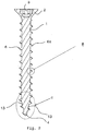
- a screw according to the invention in particular made of metal or reinforced plastic, in particular dowel screw, is shown.
- a screw has a screw shaft 1 with the total length l.
- a screw head 2 with a force application 3 is formed, and at an end of the screw shaft 1 opposite the screw head 2 there is a screw tip 4 which tapers towards its free end.
- the screw according to the invention has a screw thread 6 which runs at least over a section of the screw shaft 1 and which extends or runs as far as the free end of the screw tip 4.
- This screw thread is designed as a self-tapping screw thread.
- the screw thread 6 runs beginning at the screw head 2 to the screw tip 4 and ends at the free end of the screw tip 4.
- a single-start screw thread 6 is formed with a helical thread 6a.
- a multi-start screw thread is present on the screw shaft 1 and / or on the screw tip 4.
- the thread 6a of the screw thread 6 is triangular in cross section, seen in longitudinal section, with two thread flanks 8, 9 intersecting in a flank tip 7, see Fig. 4 , the flank tip 7 being rounded.
- the nominal diameter of the screw corresponds to the external diameter of the screw thread 6 located on the screw shaft 1, specifically in the region of the largest external diameter of the screw thread 6.
- the screw thread 6 has an outer thread diameter of the same size throughout in the area of the threaded shaft. In the illustrated embodiment, the outer thread diameter decreases in the region of the screw tip 4 towards the free end of the screw tip 4.
- the radius of the rounding of the rounded flank tip 7 is 1% to 10%, in particular 2% of the nominal diameter of the screw.
- the screw thread 6 is designed according to the invention such that the thread flanks 8, 9 of the thread 6a are formed from two flank sections 11, 12 which enclose an obtuse angle with each other, the flank section 11 beginning on the screw shaft 1 being an has a radial height H1 perpendicular to a longitudinal axis XX of the screw shaft 1, and the adjoining flank section 12 has a radial height H2 perpendicular to the longitudinal axis XX and ends in the rounded flank tip 7, the sum of the radial heights H1 and H2 forming the thread height H. .
- the radial height H1 of the flank section 11 is greater than / equal to 30% and less than / equal to 70% of the thread height H of the thread 6a
- the radial height H2 of the flank section 12 is greater than / equal to 30% and less than / equal to 70% of the total height H. of the thread 6a. It is particularly advantageous if the radial height H1 is equal to the radial height H2.
- Fig. 4 it can be seen in particular when the screw tip 4 is rounded at its free end with a rounding 4a.
- the radius of the rounding 4a of the rounded screw tip 4 is in particular 5% to 20%, preferably 10% of the nominal diameter of the screw.
- the rounding prevents the point from digging into the material of the dowel if it is not screwed in centrically. Instead, the The screw tip is steered into the hole of the dowel nut, in particular by a slight deformation of the dowel.
- the screw tip 4 seen in longitudinal section, has concave side surfaces 13, so that the screw tip 4 has a concave outer contour. This reduces the resistance to screwing the screw into the dowel nut.
- the side surfaces 13 of the screw tip 4 enclose an acute angle W with a size in a range from 20 ° to 40 ° at their point of intersection.
- the screw tip 4 is formed in two sections 14, 15 which, viewed in the longitudinal direction, lie one behind the other, the section 15 ending at the free end of the screw tip 4 having side surfaces which together form an acute angle W2 with a size in a range from 10 ° to Include 20 °, in particular with a size of 15 °, and the adjoining section 14 running in the direction of the screw head with its side faces an acute angle W1 with a size in a range of 20 ° to 40 °, in particular with a size of 30 °, includes.
- the angle W is smaller than the angle W1 and larger than the angle W2. The same effect is achieved through the angular dimensioning as through a concavity.
- the screw thread 6 has a thread pitch which is 35% to 70%, in particular 60% to 70% of the nominal diameter of the screw.
- the dowel is larger than in the rest of the shank area of the screw shank 1. This quickly knots the dowel nut.
- a screw according to the invention is expediently dimensioned in such a way that the nominal diameter has 60% to 90% of a bore diameter of a bore present in a component, in particular the outer diameter of the thread is 70% to 80% of the bore diameter.
- a screw according to the invention is dimensioned such that its outside diameter is 1 mm to 2.5 mm smaller than the nominal diameter of a dowel with which the screw according to the invention is used.
- the nominal diameter of the anchor corresponds to the hole diameter of a hole in which the anchor is inserted. This optimizes the function of the anchor.
- the screw head 2 of a screw according to the invention can be designed as a countersunk head, but other head shapes are also possible.
- the ratio l 1 / l 2 between the length l 1 of the thread-free section 1a of the screw shaft 1 ending at the screw head 2 to the length l 2 of the section 1b having the screw thread 6 up to the beginning of the Screw tip 4 preferably 20/80, 50/50 or 40/60 based on the total length l of the screw shaft 1.
- Such a partially threaded screw is in Fig. 5 shown, with this partially threaded screw otherwise, as far as the design is concerned, as to the Figs. 1 to 4 may be designed as described. Due to the formation of the partial thread, the Tightening the dowel nut and thereby improving the holding forces.
Landscapes
- Engineering & Computer Science (AREA)
- General Engineering & Computer Science (AREA)
- Mechanical Engineering (AREA)
- Physics & Mathematics (AREA)
- Geometry (AREA)
- Life Sciences & Earth Sciences (AREA)
- Chemical & Material Sciences (AREA)
- Dispersion Chemistry (AREA)
- Wood Science & Technology (AREA)
- Surgical Instruments (AREA)
- Mutual Connection Of Rods And Tubes (AREA)
Claims (19)
- Vis, en particulier vis à cheville, présentant une tige de vis (1) dotée d'une tête de vis (2) disposée à une extrémité de la tige et comportant une prise de force (3) et une pointe de vis (4) opposée à la tête de vis (2) et réalisée à l'extrémité de la tige de vis (1) et qui se rétrécit en direction de son extrémité libre, de même qu'un filet (6) s'étendant au moins sur une section de la tige de vis (1) et au-dessus de la pointe de vis (4) et dont le pas de filetage (6a) possède une section transversale triangulaire, vue en section longitudinale, dotée de deux flancs filetés (8, 9) se coupant dans une pointe de flanc (7),
caractérisée en ce que
la pointe de flanc (7) est arrondie, un rayon de l'arrondi de la pointe de flanc arrondie (7) étant sélectionné dans un ordre de grandeur de 1 % à 10 % du diamètre nominal de la vis et
les flancs filetés (8, 9) étant constitués respectivement de deux sections de flancs (11,12) qui circonscrivent l'un avec l'autre un angle obtus,a) la section de flanc (11) commençant au niveau de la tige de vis (1) présentant une hauteur radiale (H1) perpendiculairement à l'axe longitudinal (X-X) de la tige de vis (1), etb) la section de flanc s'y raccordant (12) possédant une hauteur radiale (H2) perpendiculairement à l'axe longitudinal (X-X) de la tige de vis (1), et se terminant dans la pointe de flanc arrondie (7),la somme des hauteurs radiales (H1, H2) équivalant à la hauteur du filet (H). - Vis, en particulier, en particulier vis à cheville, présentant une tige de vis (1) dotée d'une tête de vis (2) disposée à une extrémité de la tige et comportant une prise de force (3) et une pointe de vis (4) opposée à la tête de vis (2) et réalisée à l'extrémité de la tige de vis (1) et qui se rétrécit en direction de son extrémité libre, de même qu'un filet (6) s'étendant au moins sur une section de la tige de vis (1) et au-dessus de la pointe de vis (4) et dont le pas de filetage (6a) possède une section transversale triangulaire, vue en section longitudinale, dotée de deux flancs filetés (8, 9) se coupant dans une pointe de flanc (7),
caractérisée en ce que
la pointe de flanc (7) est arrondie, un rayon de l'arrondi de la pointe de flanc arrondi (7) étant sélectionné dans un ordre de grandeur de 1 % à 10 % du diamètre nominal de la vis et
la pointe de vis (4) présentant, à son extrémité libre,a) des surfaces latérales (13) s'étendant de manière concave vues en coupe longitudinale, de sorte que la pointe de vis (4) possède un contour concave oub) vues en coupe longitudinale, dans une première zone (14) adjacente à la tige de vis (1), ses surfaces latérales (13) circonscrivent à leur point d'intersection un angle aigu (W1) d'un ordre de grandeur situé dans une plage de 20° à 40°, en particulier un ordre de grandeur de 30°, et, dans une seconde zone (15) s'y raccordant et s'étendant jusqu'à l'extrémité libre de la pointe de vis (4), ses surfaces latérales (13) circonscrivent un angle aigu (W2) d'un ordre de grandeur situé dans une plage de 10° à 20°, de préférence une plage de 15°, l'angle (W) étant inférieur à l'angle (W1) et l'angle (W) étant supérieur à l'angle (W2). - Vis selon la revendication 1 ou 2,
caractérisée en ce que le rayon de l'arrondi de la pointe de flanc arrondie (7) représente 2 % du diamètre nominal de la vis. - Vis selon la revendication 2,
caractérisée en ce que les flancs filetés (8, 9) sont constitués respectivement de deux sections de flancs (11,12) qui circonscrivent l'une avec l'autre un angle obtus, la section de flanc (11) commençant au niveau de la tige de vis (1) présentant une hauteur radiale (H1) perpendiculairement à l'axe longitudinal (X-X) de la tige de vis (1), et la section de flanc s'y raccordant (12) possédant une hauteur radiale (H2) perpendiculairement à l'axe longitudinal (X-X) de la tige de vis (1), et se terminant dans la pointe de flanc arrondie (7), la somme des hauteurs radiales (H1, H2) équivalant à la hauteur du filet (H). - Vis selon la revendication 1 ou 4,
caractérisée en ce que la hauteur radiale (H1) est supérieure ou égale à 30 % et inférieure ou égale à 70 % de la hauteur totale (H), et que la hauteur radiale (H2) est supérieure ou égale à 30 % et inférieurs ou égale à 70 % de la hauteur radiale totale (H). - Vis selon la revendication 5,
caractérisée en ce que la hauteur radiale (H1) est égale à la hauteur radiale (H2). - Vis selon une des revendications 1 à 6,
caractérisée en ce que la pointe de vis (4) est arrondie à son extrémité libre, le rayon de l'arrondi (4a) de la pointe de vis arrondie (4) représentant 5 % à 20 %, en particulier 10 % du diamètre nominal de la vis. - Vis selon une des revendications 1 à 7,
caractérisée en ce que la pointe de vis (4), à son extrémité libre, au point d'intersection, circonscrit dans ses surfaces latérales (13) un angle aigu (W) d'un ordre de grandeur situé dans une plage de 20° à 40°. - Vis selon la revendication 1,
caractérisée en ce que la pointe de vis (4), à son extrémité libre, vue en section longitudinale, présente des surfaces latérales (13) à extension concave, de sorte que la pointe de vis (4) possède un contour concave. - Vis selon la revendication 1,
caractérisée en ce que, vues en coupe longitudinale, dans une première zone (14) adjacente à la tige de vis (1), ses surfaces latérales (13) circonscrivent à leur point d'intersection un angle aigu (W1) d'un ordre de grandeur situé dans une plage de 20° à 40°, en particulier un ordre de grandeur de 30°, et, dans une seconde zone (15) s'y raccordant et s'étendant jusqu'à l'extrémité libre de la pointe de vis (4), ses surfaces latérales (13) circonscrivent un angle aigu (W2) d'un ordre de grandeur situé dans une plage de 10° à 20°, de préférence un ordre de grandeur de 15°, l'angle (W) étant en particulier inférieur à l'angle (W1) et l'angle (W) étant supérieur à l'angle (W2). - Vis selon une des revendications 1 à 10,
caractérisée en ce que le filet (6) présente une pente qui représente 35 % à 70 %, en particulier 60 % à 70 %, du diamètre nominal du filet (6). - Vis selon une des revendications 1 à 11,
caractérisée en ce que la pente du filet (6), au niveau de la pointe de vis (4) et dans une zone de la tige adjacente à la pointe de vis (4), qui représente en particulier 1/4 à 1/2 d'une longueur de vissage de la tige de vis (1), est supérieure à ce qu'elle est dans le reste de la zone de tige de la tige de vis (1). - Vis selon une des revendications 1 à 12,
caractérisée en ce que les sections de flancs (8, 9), au niveau de leurs sections superficielles (11), circonscrivent avec la hauteur radiale (H1) un angle aigu de 20° à 40°, de préférence 30°. - Vis selon une des revendications 1 à 13,
caractérisée en ce que les sections de flancs (8, 9), au niveau de leurs sections superficielles (12), circonscrivent entre elles avec la hauteur radiale (H2) un angle aigu de 50° à 70°, de préférence 50°. - Vis selon une des revendications 1 à 14,
caractérisée en ce que le diamètre du filet (6) se réduit sur la longueur de la pointe de vis (4) vers l'extrémité libre de celle-ci. - Vis selon une des revendications 1 à 15,
caractérisée en ce que le filet (6) est réalisé seulement sur une longueur partielle (l2) de la tige de vis (1) commençant à la pointe de vis (4) et présente une section de tige (1a) non filetée s'y raccordant. - Vis selon la revendication 16,
caractérisée en ce que le rapport (l1/l2) de la longueur (l1) de la section de tige non filetée (1a) et de la longueur (l2) de la section de tige (1b) présentant le filet (6) par rapport à la longueur totale (1) du filet (1) s'élève à l1/l2 = 20/80 ou 50/50 ou 40/60. - Vis selon une des revendications 1 à 17,
caractérisée en ce qu'elle est composée de métal ou de plastique renforcé. - Combinaison d'une vis selon une des revendications 1 à 18 et d'une cheville,
caractérisée en ce que le diamètre extérieur du filet (6) est constant au niveau de la tige de vis (1) et est inférieur de 1 mm à 2,5 mm à un diamètre nominal de la cheville à utiliser avec la vis.
Applications Claiming Priority (3)
| Application Number | Priority Date | Filing Date | Title |
|---|---|---|---|
| DE102016112357.9A DE102016112357A1 (de) | 2016-07-06 | 2016-07-06 | "Dübelschraube" |
| DE202017100612.3U DE202017100612U1 (de) | 2016-07-06 | 2017-02-06 | Dübelschraube |
| PCT/EP2017/063042 WO2018007069A1 (fr) | 2016-07-06 | 2017-05-30 | Vis à cheville |
Publications (3)
| Publication Number | Publication Date |
|---|---|
| EP3482092A1 EP3482092A1 (fr) | 2019-05-15 |
| EP3482092B1 true EP3482092B1 (fr) | 2020-09-23 |
| EP3482092B9 EP3482092B9 (fr) | 2021-04-07 |
Family
ID=60163585
Family Applications (1)
| Application Number | Title | Priority Date | Filing Date |
|---|---|---|---|
| EP17727568.2A Active EP3482092B9 (fr) | 2016-07-06 | 2017-05-30 | Vis à cheville |
Country Status (6)
| Country | Link |
|---|---|
| US (1) | US10954987B2 (fr) |
| EP (1) | EP3482092B9 (fr) |
| AU (1) | AU2017294325B2 (fr) |
| DE (2) | DE102016112357A1 (fr) |
| ES (1) | ES2833203T3 (fr) |
| WO (1) | WO2018007069A1 (fr) |
Families Citing this family (5)
| Publication number | Priority date | Publication date | Assignee | Title |
|---|---|---|---|---|
| DE102020106119B3 (de) | 2020-03-06 | 2021-09-09 | Günter Weippert | Schraube |
| USD959970S1 (en) * | 2020-08-18 | 2022-08-09 | Kobert & Company, Inc. | Screw |
| USD959971S1 (en) * | 2020-08-18 | 2022-08-09 | Kobert & Company, Inc. | Screw |
| CN113476128B (zh) * | 2021-08-23 | 2022-09-23 | 北京市春立正达医疗器械股份有限公司 | 一种抗拔出骨螺钉 |
| DE102022121435A1 (de) | 2022-08-24 | 2024-02-29 | Ejot Se & Co. Kg | Schraube für die Direktverschraubung in ein Bauteil |
Family Cites Families (21)
| Publication number | Priority date | Publication date | Assignee | Title |
|---|---|---|---|---|
| US1369156A (en) * | 1920-02-03 | 1921-02-22 | Locking screw-thread | |
| US2788046A (en) * | 1952-12-15 | 1957-04-09 | Rosan Joseph | Screw thread construction comprising conventional truncated threads with integral locking thread interposed therebetween |
| US3045523A (en) | 1960-08-25 | 1962-07-24 | Nd Edgar Reed | Drill point screw having interrupted leading end threads formed by a flat chordal surface |
| US3323402A (en) * | 1965-10-08 | 1967-06-06 | Standard Pressed Steel Co | Thread forms |
| AT365750B (de) * | 1978-08-30 | 1982-02-10 | Fischer Artur Dr H C | Aus spreizduebel und befestigungsschraube bestehender befestigungssatz |
| DE3365298D1 (en) * | 1982-09-02 | 1986-09-18 | Rockenfeller Kg | Wood-screw |
| US4549754A (en) * | 1983-06-20 | 1985-10-29 | Reed Tubular Products Company | Tool joint |
| PT785308E (pt) * | 1996-01-17 | 2003-08-29 | Vossloh Werke Gmbh | Cavilha roscada de material plastico |
| DE19632838A1 (de) * | 1996-08-15 | 1998-02-19 | Wuerth Adolf Gmbh & Co Kg | Schraube mit einer selbstbohrenden Spitze |
| DE69711336T2 (de) * | 1996-11-29 | 2002-10-10 | Max Co Ltd | Selbstschneidende Schraube |
| JP4225546B2 (ja) * | 2003-10-09 | 2009-02-18 | 株式会社青山製作所 | タッピンねじ |
| DE102004021484B4 (de) * | 2004-04-30 | 2018-11-29 | Böllhoff Verbindungstechnik GmbH | Verfahren zum Herstellen einer Verbindungsanordnung |
| DE202006000479U1 (de) * | 2006-01-12 | 2006-03-16 | Abc Verbindungstechnik Gmbh & Co. Kg | Selbstlochende und gewindeformende Schraube |
| JP4684158B2 (ja) * | 2006-04-25 | 2011-05-18 | 日本パワーファスニング株式会社 | 石膏ボード締結用のもみ切り式自己穿孔ねじ |
| DE102007000154B4 (de) * | 2007-03-15 | 2023-12-07 | Hilti Aktiengesellschaft | Spanlos gewindeformende Schraube |
| US7731466B2 (en) * | 2007-11-02 | 2010-06-08 | Gm Global Technology Operations, Inc. | Thread profile modification for controlled stiffness |
| DE102010000702A1 (de) * | 2010-01-06 | 2011-07-07 | Arnold Umformtechnik GmbH & Co. KG, 74670 | Gewindeformende Schraube und ihre Verwendung |
| SG179322A1 (en) * | 2010-10-01 | 2012-04-27 | Infastech Ip Pte Ltd | Threaded fastener |
| US20130034405A1 (en) * | 2011-08-03 | 2013-02-07 | Kuo-Tai Hsu | Screw with Helical Groove for Receiving Chippings |
| DE102012107732A1 (de) * | 2012-08-22 | 2014-05-15 | Vossloh-Werke Gmbh | Kunststoffdübel für die Befestigung einer Schiene und Kombination aus einem solchen Kunststoffdübel und einer Schwellenschraube |
| US9404524B2 (en) * | 2013-07-19 | 2016-08-02 | Conti Fasteners | High performance thread rolling screw/bolt for use in an unthreaded nut anchor |
-
2016
- 2016-07-06 DE DE102016112357.9A patent/DE102016112357A1/de active Pending
-
2017
- 2017-02-06 DE DE202017100612.3U patent/DE202017100612U1/de active Active
- 2017-05-30 EP EP17727568.2A patent/EP3482092B9/fr active Active
- 2017-05-30 AU AU2017294325A patent/AU2017294325B2/en active Active
- 2017-05-30 US US16/314,381 patent/US10954987B2/en active Active
- 2017-05-30 ES ES17727568T patent/ES2833203T3/es active Active
- 2017-05-30 WO PCT/EP2017/063042 patent/WO2018007069A1/fr unknown
Non-Patent Citations (1)
| Title |
|---|
| None * |
Also Published As
| Publication number | Publication date |
|---|---|
| EP3482092A1 (fr) | 2019-05-15 |
| US10954987B2 (en) | 2021-03-23 |
| AU2017294325A1 (en) | 2019-01-17 |
| ES2833203T3 (es) | 2021-06-14 |
| WO2018007069A1 (fr) | 2018-01-11 |
| AU2017294325B2 (en) | 2022-10-20 |
| EP3482092B9 (fr) | 2021-04-07 |
| US20190203756A1 (en) | 2019-07-04 |
| DE202017100612U1 (de) | 2017-10-10 |
| DE102016112357A1 (de) | 2018-01-11 |
Similar Documents
| Publication | Publication Date | Title |
|---|---|---|
| EP3482092B1 (fr) | Vis à cheville | |
| DE60206700T2 (de) | Befestigungsvorrichtung für Knochenteile | |
| EP2257714B1 (fr) | Vis taraudeuse | |
| EP3359828B1 (fr) | Vis autotaraudeuse ayant une spirale filetee separee et differents pas angulaires partiels | |
| EP0799387B1 (fr) | Vis foreuse et taraudeuse et son procede de vissage | |
| DE2047482A1 (de) | Gewindebildende Schraube | |
| DE1625417B2 (de) | Selbstbohrende und gewindeformende Schraube | |
| DE2805071A1 (de) | Schraube | |
| DE4041765C2 (de) | Einschraubdübel | |
| DE60318117T2 (de) | Schneidschraube für die verwendung in gering dehnbaren materialien | |
| EP0068227A1 (fr) | Boulon d'ancrage | |
| EP2806174A1 (fr) | Elément de vis | |
| EP0939235B1 (fr) | Vis | |
| EP1233194A2 (fr) | Vis pour beton | |
| DE102014000940A1 (de) | Schraube, Befestigungsanordnung und Verwendung einer Schraube | |
| EP3006748B1 (fr) | Vis autotaraudeuse | |
| EP2317159A1 (fr) | Vis, notamment pour plaques fibreuses liées par du ciment | |
| DE202004002878U1 (de) | Gewindeformende Schraube | |
| EP3586015B1 (fr) | Vis | |
| EP3380737B1 (fr) | Vis à béton | |
| EP3374649B1 (fr) | Vis autotaraudeuse | |
| WO2018210637A1 (fr) | Élément vis | |
| EP0799386B1 (fr) | Vis foreuse et taraudeuse et son procede d'enfoncement | |
| DE2164666A1 (de) | Ankerbolzen | |
| DE10357550A1 (de) | Selbstschneidende Schraube für Composit-Materialien |
Legal Events
| Date | Code | Title | Description |
|---|---|---|---|
| STAA | Information on the status of an ep patent application or granted ep patent |
Free format text: STATUS: UNKNOWN |
|
| STAA | Information on the status of an ep patent application or granted ep patent |
Free format text: STATUS: THE INTERNATIONAL PUBLICATION HAS BEEN MADE |
|
| PUAI | Public reference made under article 153(3) epc to a published international application that has entered the european phase |
Free format text: ORIGINAL CODE: 0009012 |
|
| STAA | Information on the status of an ep patent application or granted ep patent |
Free format text: STATUS: REQUEST FOR EXAMINATION WAS MADE |
|
| 17P | Request for examination filed |
Effective date: 20190118 |
|
| AK | Designated contracting states |
Kind code of ref document: A1 Designated state(s): AL AT BE BG CH CY CZ DE DK EE ES FI FR GB GR HR HU IE IS IT LI LT LU LV MC MK MT NL NO PL PT RO RS SE SI SK SM TR |
|
| AX | Request for extension of the european patent |
Extension state: BA ME |
|
| DAV | Request for validation of the european patent (deleted) | ||
| DAX | Request for extension of the european patent (deleted) | ||
| GRAP | Despatch of communication of intention to grant a patent |
Free format text: ORIGINAL CODE: EPIDOSNIGR1 |
|
| STAA | Information on the status of an ep patent application or granted ep patent |
Free format text: STATUS: GRANT OF PATENT IS INTENDED |
|
| INTG | Intention to grant announced |
Effective date: 20200428 |
|
| RIN1 | Information on inventor provided before grant (corrected) |
Inventor name: LANGEWIESCHE, FRANK |
|
| GRAS | Grant fee paid |
Free format text: ORIGINAL CODE: EPIDOSNIGR3 |
|
| GRAA | (expected) grant |
Free format text: ORIGINAL CODE: 0009210 |
|
| STAA | Information on the status of an ep patent application or granted ep patent |
Free format text: STATUS: THE PATENT HAS BEEN GRANTED |
|
| AK | Designated contracting states |
Kind code of ref document: B1 Designated state(s): AL AT BE BG CH CY CZ DE DK EE ES FI FR GB GR HR HU IE IS IT LI LT LU LV MC MK MT NL NO PL PT RO RS SE SI SK SM TR |
|
| REG | Reference to a national code |
Ref country code: GB Ref legal event code: FG4D Free format text: NOT ENGLISH |
|
| REG | Reference to a national code |
Ref country code: CH Ref legal event code: EP |
|
| REG | Reference to a national code |
Ref country code: IE Ref legal event code: FG4D Free format text: LANGUAGE OF EP DOCUMENT: GERMAN |
|
| REG | Reference to a national code |
Ref country code: DE Ref legal event code: R096 Ref document number: 502017007403 Country of ref document: DE Ref country code: AT Ref legal event code: REF Ref document number: 1316657 Country of ref document: AT Kind code of ref document: T Effective date: 20201015 |
|
| REG | Reference to a national code |
Ref country code: FI Ref legal event code: FGE |
|
| REG | Reference to a national code |
Ref country code: NL Ref legal event code: FP |
|
| REG | Reference to a national code |
Ref country code: SE Ref legal event code: TRGR |
|
| PG25 | Lapsed in a contracting state [announced via postgrant information from national office to epo] |
Ref country code: GR Free format text: LAPSE BECAUSE OF FAILURE TO SUBMIT A TRANSLATION OF THE DESCRIPTION OR TO PAY THE FEE WITHIN THE PRESCRIBED TIME-LIMIT Effective date: 20201224 Ref country code: NO Free format text: LAPSE BECAUSE OF FAILURE TO SUBMIT A TRANSLATION OF THE DESCRIPTION OR TO PAY THE FEE WITHIN THE PRESCRIBED TIME-LIMIT Effective date: 20201223 Ref country code: BG Free format text: LAPSE BECAUSE OF FAILURE TO SUBMIT A TRANSLATION OF THE DESCRIPTION OR TO PAY THE FEE WITHIN THE PRESCRIBED TIME-LIMIT Effective date: 20201223 Ref country code: HR Free format text: LAPSE BECAUSE OF FAILURE TO SUBMIT A TRANSLATION OF THE DESCRIPTION OR TO PAY THE FEE WITHIN THE PRESCRIBED TIME-LIMIT Effective date: 20200923 |
|
| PG25 | Lapsed in a contracting state [announced via postgrant information from national office to epo] |
Ref country code: LV Free format text: LAPSE BECAUSE OF FAILURE TO SUBMIT A TRANSLATION OF THE DESCRIPTION OR TO PAY THE FEE WITHIN THE PRESCRIBED TIME-LIMIT Effective date: 20200923 Ref country code: RS Free format text: LAPSE BECAUSE OF FAILURE TO SUBMIT A TRANSLATION OF THE DESCRIPTION OR TO PAY THE FEE WITHIN THE PRESCRIBED TIME-LIMIT Effective date: 20200923 |
|
| REG | Reference to a national code |
Ref country code: CH Ref legal event code: PK Free format text: BERICHTIGUNG B9 |
|
| REG | Reference to a national code |
Ref country code: LT Ref legal event code: MG4D |
|
| PG25 | Lapsed in a contracting state [announced via postgrant information from national office to epo] |
Ref country code: EE Free format text: LAPSE BECAUSE OF FAILURE TO SUBMIT A TRANSLATION OF THE DESCRIPTION OR TO PAY THE FEE WITHIN THE PRESCRIBED TIME-LIMIT Effective date: 20200923 Ref country code: SM Free format text: LAPSE BECAUSE OF FAILURE TO SUBMIT A TRANSLATION OF THE DESCRIPTION OR TO PAY THE FEE WITHIN THE PRESCRIBED TIME-LIMIT Effective date: 20200923 Ref country code: LT Free format text: LAPSE BECAUSE OF FAILURE TO SUBMIT A TRANSLATION OF THE DESCRIPTION OR TO PAY THE FEE WITHIN THE PRESCRIBED TIME-LIMIT Effective date: 20200923 Ref country code: PT Free format text: LAPSE BECAUSE OF FAILURE TO SUBMIT A TRANSLATION OF THE DESCRIPTION OR TO PAY THE FEE WITHIN THE PRESCRIBED TIME-LIMIT Effective date: 20210125 Ref country code: RO Free format text: LAPSE BECAUSE OF FAILURE TO SUBMIT A TRANSLATION OF THE DESCRIPTION OR TO PAY THE FEE WITHIN THE PRESCRIBED TIME-LIMIT Effective date: 20200923 Ref country code: CZ Free format text: LAPSE BECAUSE OF FAILURE TO SUBMIT A TRANSLATION OF THE DESCRIPTION OR TO PAY THE FEE WITHIN THE PRESCRIBED TIME-LIMIT Effective date: 20200923 |
|
| PG25 | Lapsed in a contracting state [announced via postgrant information from national office to epo] |
Ref country code: AL Free format text: LAPSE BECAUSE OF FAILURE TO SUBMIT A TRANSLATION OF THE DESCRIPTION OR TO PAY THE FEE WITHIN THE PRESCRIBED TIME-LIMIT Effective date: 20200923 Ref country code: IS Free format text: LAPSE BECAUSE OF FAILURE TO SUBMIT A TRANSLATION OF THE DESCRIPTION OR TO PAY THE FEE WITHIN THE PRESCRIBED TIME-LIMIT Effective date: 20210123 |
|
| REG | Reference to a national code |
Ref country code: ES Ref legal event code: FG2A Ref document number: 2833203 Country of ref document: ES Kind code of ref document: T3 Effective date: 20210614 |
|
| REG | Reference to a national code |
Ref country code: DE Ref legal event code: R097 Ref document number: 502017007403 Country of ref document: DE |
|
| PG25 | Lapsed in a contracting state [announced via postgrant information from national office to epo] |
Ref country code: SK Free format text: LAPSE BECAUSE OF FAILURE TO SUBMIT A TRANSLATION OF THE DESCRIPTION OR TO PAY THE FEE WITHIN THE PRESCRIBED TIME-LIMIT Effective date: 20200923 |
|
| PLBE | No opposition filed within time limit |
Free format text: ORIGINAL CODE: 0009261 |
|
| STAA | Information on the status of an ep patent application or granted ep patent |
Free format text: STATUS: NO OPPOSITION FILED WITHIN TIME LIMIT |
|
| PG25 | Lapsed in a contracting state [announced via postgrant information from national office to epo] |
Ref country code: DK Free format text: LAPSE BECAUSE OF FAILURE TO SUBMIT A TRANSLATION OF THE DESCRIPTION OR TO PAY THE FEE WITHIN THE PRESCRIBED TIME-LIMIT Effective date: 20200923 Ref country code: SI Free format text: LAPSE BECAUSE OF FAILURE TO SUBMIT A TRANSLATION OF THE DESCRIPTION OR TO PAY THE FEE WITHIN THE PRESCRIBED TIME-LIMIT Effective date: 20200923 |
|
| 26N | No opposition filed |
Effective date: 20210624 |
|
| PG25 | Lapsed in a contracting state [announced via postgrant information from national office to epo] |
Ref country code: MC Free format text: LAPSE BECAUSE OF FAILURE TO SUBMIT A TRANSLATION OF THE DESCRIPTION OR TO PAY THE FEE WITHIN THE PRESCRIBED TIME-LIMIT Effective date: 20200923 |
|
| PG25 | Lapsed in a contracting state [announced via postgrant information from national office to epo] |
Ref country code: IE Free format text: LAPSE BECAUSE OF NON-PAYMENT OF DUE FEES Effective date: 20210530 |
|
| PG25 | Lapsed in a contracting state [announced via postgrant information from national office to epo] |
Ref country code: CY Free format text: LAPSE BECAUSE OF FAILURE TO SUBMIT A TRANSLATION OF THE DESCRIPTION OR TO PAY THE FEE WITHIN THE PRESCRIBED TIME-LIMIT Effective date: 20200923 |
|
| PGFP | Annual fee paid to national office [announced via postgrant information from national office to epo] |
Ref country code: LU Payment date: 20230517 Year of fee payment: 7 |
|
| PG25 | Lapsed in a contracting state [announced via postgrant information from national office to epo] |
Ref country code: HU Free format text: LAPSE BECAUSE OF FAILURE TO SUBMIT A TRANSLATION OF THE DESCRIPTION OR TO PAY THE FEE WITHIN THE PRESCRIBED TIME-LIMIT; INVALID AB INITIO Effective date: 20170530 |
|
| PGFP | Annual fee paid to national office [announced via postgrant information from national office to epo] |
Ref country code: NL Payment date: 20230519 Year of fee payment: 7 Ref country code: IT Payment date: 20230531 Year of fee payment: 7 Ref country code: FR Payment date: 20230517 Year of fee payment: 7 Ref country code: ES Payment date: 20230601 Year of fee payment: 7 Ref country code: DE Payment date: 20230605 Year of fee payment: 7 Ref country code: CH Payment date: 20230605 Year of fee payment: 7 |
|
| PGFP | Annual fee paid to national office [announced via postgrant information from national office to epo] |
Ref country code: SE Payment date: 20230522 Year of fee payment: 7 Ref country code: PL Payment date: 20230522 Year of fee payment: 7 Ref country code: FI Payment date: 20230523 Year of fee payment: 7 Ref country code: AT Payment date: 20230516 Year of fee payment: 7 |
|
| PGFP | Annual fee paid to national office [announced via postgrant information from national office to epo] |
Ref country code: BE Payment date: 20230517 Year of fee payment: 7 |
|
| PGFP | Annual fee paid to national office [announced via postgrant information from national office to epo] |
Ref country code: GB Payment date: 20230508 Year of fee payment: 7 |
|
| PG25 | Lapsed in a contracting state [announced via postgrant information from national office to epo] |
Ref country code: MK Free format text: LAPSE BECAUSE OF FAILURE TO SUBMIT A TRANSLATION OF THE DESCRIPTION OR TO PAY THE FEE WITHIN THE PRESCRIBED TIME-LIMIT Effective date: 20200923 |