EP3482092B1 - Plug screw - Google Patents
Plug screw Download PDFInfo
- Publication number
- EP3482092B1 EP3482092B1 EP17727568.2A EP17727568A EP3482092B1 EP 3482092 B1 EP3482092 B1 EP 3482092B1 EP 17727568 A EP17727568 A EP 17727568A EP 3482092 B1 EP3482092 B1 EP 3482092B1
- Authority
- EP
- European Patent Office
- Prior art keywords
- screw
- tip
- section
- thread
- shaft
- Prior art date
- Legal status (The legal status is an assumption and is not a legal conclusion. Google has not performed a legal analysis and makes no representation as to the accuracy of the status listed.)
- Active
Links
- 230000001154 acute effect Effects 0.000 claims description 13
- 230000007423 decrease Effects 0.000 claims description 2
- 239000002184 metal Substances 0.000 claims description 2
- 239000002990 reinforced plastic Substances 0.000 claims description 2
- 238000010079 rubber tapping Methods 0.000 description 5
- 230000000694 effects Effects 0.000 description 3
- 239000004033 plastic Substances 0.000 description 3
- 230000015572 biosynthetic process Effects 0.000 description 2
- 230000006378 damage Effects 0.000 description 2
- 230000001771 impaired effect Effects 0.000 description 1
- 239000000463 material Substances 0.000 description 1
- 230000035515 penetration Effects 0.000 description 1
- 239000007787 solid Substances 0.000 description 1
- 239000004575 stone Substances 0.000 description 1
- 230000003313 weakening effect Effects 0.000 description 1
- 239000002023 wood Substances 0.000 description 1
Images


Classifications
-
- F—MECHANICAL ENGINEERING; LIGHTING; HEATING; WEAPONS; BLASTING
- F16—ENGINEERING ELEMENTS AND UNITS; GENERAL MEASURES FOR PRODUCING AND MAINTAINING EFFECTIVE FUNCTIONING OF MACHINES OR INSTALLATIONS; THERMAL INSULATION IN GENERAL
- F16B—DEVICES FOR FASTENING OR SECURING CONSTRUCTIONAL ELEMENTS OR MACHINE PARTS TOGETHER, e.g. NAILS, BOLTS, CIRCLIPS, CLAMPS, CLIPS OR WEDGES; JOINTS OR JOINTING
- F16B25/00—Screws that cut thread in the body into which they are screwed, e.g. wood screws
- F16B25/0036—Screws that cut thread in the body into which they are screwed, e.g. wood screws characterised by geometric details of the screw
- F16B25/0084—Screws that cut thread in the body into which they are screwed, e.g. wood screws characterised by geometric details of the screw characterised by geometric details of the tip
-
- F—MECHANICAL ENGINEERING; LIGHTING; HEATING; WEAPONS; BLASTING
- F16—ENGINEERING ELEMENTS AND UNITS; GENERAL MEASURES FOR PRODUCING AND MAINTAINING EFFECTIVE FUNCTIONING OF MACHINES OR INSTALLATIONS; THERMAL INSULATION IN GENERAL
- F16B—DEVICES FOR FASTENING OR SECURING CONSTRUCTIONAL ELEMENTS OR MACHINE PARTS TOGETHER, e.g. NAILS, BOLTS, CIRCLIPS, CLAMPS, CLIPS OR WEDGES; JOINTS OR JOINTING
- F16B25/00—Screws that cut thread in the body into which they are screwed, e.g. wood screws
- F16B25/001—Screws that cut thread in the body into which they are screwed, e.g. wood screws characterised by the material of the body into which the screw is screwed
- F16B25/0015—Screws that cut thread in the body into which they are screwed, e.g. wood screws characterised by the material of the body into which the screw is screwed the material being a soft organic material, e.g. wood or plastic
-
- F—MECHANICAL ENGINEERING; LIGHTING; HEATING; WEAPONS; BLASTING
- F16—ENGINEERING ELEMENTS AND UNITS; GENERAL MEASURES FOR PRODUCING AND MAINTAINING EFFECTIVE FUNCTIONING OF MACHINES OR INSTALLATIONS; THERMAL INSULATION IN GENERAL
- F16B—DEVICES FOR FASTENING OR SECURING CONSTRUCTIONAL ELEMENTS OR MACHINE PARTS TOGETHER, e.g. NAILS, BOLTS, CIRCLIPS, CLAMPS, CLIPS OR WEDGES; JOINTS OR JOINTING
- F16B25/00—Screws that cut thread in the body into which they are screwed, e.g. wood screws
- F16B25/0036—Screws that cut thread in the body into which they are screwed, e.g. wood screws characterised by geometric details of the screw
- F16B25/0042—Screws that cut thread in the body into which they are screwed, e.g. wood screws characterised by geometric details of the screw characterised by the geometry of the thread, the thread being a ridge wrapped around the shaft of the screw
- F16B25/0047—Screws that cut thread in the body into which they are screwed, e.g. wood screws characterised by geometric details of the screw characterised by the geometry of the thread, the thread being a ridge wrapped around the shaft of the screw the ridge being characterised by its cross-section in the plane of the shaft axis
-
- F—MECHANICAL ENGINEERING; LIGHTING; HEATING; WEAPONS; BLASTING
- F16—ENGINEERING ELEMENTS AND UNITS; GENERAL MEASURES FOR PRODUCING AND MAINTAINING EFFECTIVE FUNCTIONING OF MACHINES OR INSTALLATIONS; THERMAL INSULATION IN GENERAL
- F16B—DEVICES FOR FASTENING OR SECURING CONSTRUCTIONAL ELEMENTS OR MACHINE PARTS TOGETHER, e.g. NAILS, BOLTS, CIRCLIPS, CLAMPS, CLIPS OR WEDGES; JOINTS OR JOINTING
- F16B25/00—Screws that cut thread in the body into which they are screwed, e.g. wood screws
- F16B25/0036—Screws that cut thread in the body into which they are screwed, e.g. wood screws characterised by geometric details of the screw
- F16B25/0042—Screws that cut thread in the body into which they are screwed, e.g. wood screws characterised by geometric details of the screw characterised by the geometry of the thread, the thread being a ridge wrapped around the shaft of the screw
- F16B25/0057—Screws that cut thread in the body into which they are screwed, e.g. wood screws characterised by geometric details of the screw characterised by the geometry of the thread, the thread being a ridge wrapped around the shaft of the screw the screw having distinct axial zones, e.g. multiple axial thread sections with different pitch or thread cross-sections
-
- F—MECHANICAL ENGINEERING; LIGHTING; HEATING; WEAPONS; BLASTING
- F16—ENGINEERING ELEMENTS AND UNITS; GENERAL MEASURES FOR PRODUCING AND MAINTAINING EFFECTIVE FUNCTIONING OF MACHINES OR INSTALLATIONS; THERMAL INSULATION IN GENERAL
- F16B—DEVICES FOR FASTENING OR SECURING CONSTRUCTIONAL ELEMENTS OR MACHINE PARTS TOGETHER, e.g. NAILS, BOLTS, CIRCLIPS, CLAMPS, CLIPS OR WEDGES; JOINTS OR JOINTING
- F16B25/00—Screws that cut thread in the body into which they are screwed, e.g. wood screws
- F16B25/10—Screws performing an additional function to thread-forming, e.g. drill screws or self-piercing screws
- F16B25/103—Screws performing an additional function to thread-forming, e.g. drill screws or self-piercing screws by means of a drilling screw-point, i.e. with a cutting and material removing action
-
- F—MECHANICAL ENGINEERING; LIGHTING; HEATING; WEAPONS; BLASTING
- F16—ENGINEERING ELEMENTS AND UNITS; GENERAL MEASURES FOR PRODUCING AND MAINTAINING EFFECTIVE FUNCTIONING OF MACHINES OR INSTALLATIONS; THERMAL INSULATION IN GENERAL
- F16B—DEVICES FOR FASTENING OR SECURING CONSTRUCTIONAL ELEMENTS OR MACHINE PARTS TOGETHER, e.g. NAILS, BOLTS, CIRCLIPS, CLAMPS, CLIPS OR WEDGES; JOINTS OR JOINTING
- F16B25/00—Screws that cut thread in the body into which they are screwed, e.g. wood screws
Definitions
- the present invention relates to a self-tapping screw, in particular a dowel screw according to the preamble of claims 1 and 2.
- the documents EP 1 591 675 A and EP 0 824 198 A show previously known screws.
- Self-tapping screws are used in a variety of ways, especially for screwing into wood or plastic parts. For use in stone or the like, they are used in conjunction with plastic dowels, the plastic dowel being inserted into a pre-drilled hole and then the screw being screwed in.
- the present invention is based on the object of creating a self-tapping screw which reduces the risk of digging into the wall of the dowel, especially if it is screwed in at an angle, and also minimizes damage to the dowel nut at hollow wall dowels.
- flank tip of the thread running on the screw shaft is rounded, with a radius of the rounding of the rounded flank tip in the size of 1% to 10% of the nominal diameter of the screw.
- the rounded flank tip of the thread prevents the thread from cutting into the wall of the dowel in such a way that this results in partial or complete destruction of the wall of the dowel.
- the radius of the rounding of the rounded thread tip is advantageously 2% of the nominal diameter of the screw.
- a first variant according to the invention comprises the features that the thread flanks of the thread turn are each formed from two flank sections which enclose an obtuse angle with one another, the flank section beginning on the threaded shaft having a radial height H1 perpendicular to the longitudinal axis of the screw shank and the flank section adjoining it having a has radial height H2 perpendicular to the longitudinal axis of the screw shaft and ends in the rounded flank tip, the sum of H1 and H2 forming the thread height H of the thread.
- This embodiment according to the invention achieves an increased expansion effect when screwing into the respective dowel.
- flank sections with the radial height H1 which are opposite one another, enclose an acute angle of 20 ° to 40 °, preferably 30 °, when viewed in longitudinal section. It is also advantageous according to the invention if the mutually opposite flank sections with the radial height H2 enclose an acute angle of 50 ° to 70 °, preferably 50 °, with one another.
- the above dimensioning of the respective angles, which are enclosed by the flank sections with one another optimizes the expanding effect of the screw according to the invention in the dowel, it also allows easy penetration of the flanks of the thread into the "dowel nut".
- the screw tip at the end of the screw shaft is rounded at its free end with a rounding.
- the radius of the rounding is advantageously 10% of the nominal diameter of the screw according to the invention, with a range of 5% to 20% of the nominal diameter of the screw being advantageously able to be selected.
- a second variant of the invention comprises the feature that the screw tip has concave side surfaces as seen in longitudinal section.
- a screw tip designed in this way with a concave outline improves the centering of the screw according to the invention when it is screwed into the so-called dowel nut of the hollow wall dowel and enables easy and secure screwing.
- the side surfaces of the screw tip enclose an acute angle W with a size in a range from 20 ° to 40 ° at their point of intersection.
- an angle W1 with a size in a range from 20 ° to 40 °, in particular with a size of 30 ° is enclosed by its side surfaces in a first section of the screw tip adjoining the screw shank and in a second section adjoining it from its side faces include an angle W2 with a size in a range from 10 ° to 20 °, in particular with a size of 15 °.
- the angle W is smaller than the angle W1 and larger than the angle W2.
- the screw thread has a greater pitch in the area of the screw tip and in an adjacent shank area than in the rest of the shank area. This results in faster knotting and better expansion of the dowel.
- the screw according to the invention can be advantageous to design as a partially threaded screw.
- a screw according to the invention in particular made of metal or reinforced plastic, in particular dowel screw, is shown.
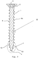
- a screw has a screw shaft 1 with the total length l.
- a screw head 2 with a force application 3 is formed, and at an end of the screw shaft 1 opposite the screw head 2 there is a screw tip 4 which tapers towards its free end.
- the screw according to the invention has a screw thread 6 which runs at least over a section of the screw shaft 1 and which extends or runs as far as the free end of the screw tip 4.
- This screw thread is designed as a self-tapping screw thread.
- the screw thread 6 runs beginning at the screw head 2 to the screw tip 4 and ends at the free end of the screw tip 4.
- a single-start screw thread 6 is formed with a helical thread 6a.
- a multi-start screw thread is present on the screw shaft 1 and / or on the screw tip 4.
- the thread 6a of the screw thread 6 is triangular in cross section, seen in longitudinal section, with two thread flanks 8, 9 intersecting in a flank tip 7, see Fig. 4 , the flank tip 7 being rounded.
- the nominal diameter of the screw corresponds to the external diameter of the screw thread 6 located on the screw shaft 1, specifically in the region of the largest external diameter of the screw thread 6.
- the screw thread 6 has an outer thread diameter of the same size throughout in the area of the threaded shaft. In the illustrated embodiment, the outer thread diameter decreases in the region of the screw tip 4 towards the free end of the screw tip 4.
- the radius of the rounding of the rounded flank tip 7 is 1% to 10%, in particular 2% of the nominal diameter of the screw.
- the screw thread 6 is designed according to the invention such that the thread flanks 8, 9 of the thread 6a are formed from two flank sections 11, 12 which enclose an obtuse angle with each other, the flank section 11 beginning on the screw shaft 1 being an has a radial height H1 perpendicular to a longitudinal axis XX of the screw shaft 1, and the adjoining flank section 12 has a radial height H2 perpendicular to the longitudinal axis XX and ends in the rounded flank tip 7, the sum of the radial heights H1 and H2 forming the thread height H. .
- the radial height H1 of the flank section 11 is greater than / equal to 30% and less than / equal to 70% of the thread height H of the thread 6a
- the radial height H2 of the flank section 12 is greater than / equal to 30% and less than / equal to 70% of the total height H. of the thread 6a. It is particularly advantageous if the radial height H1 is equal to the radial height H2.
- Fig. 4 it can be seen in particular when the screw tip 4 is rounded at its free end with a rounding 4a.
- the radius of the rounding 4a of the rounded screw tip 4 is in particular 5% to 20%, preferably 10% of the nominal diameter of the screw.
- the rounding prevents the point from digging into the material of the dowel if it is not screwed in centrically. Instead, the The screw tip is steered into the hole of the dowel nut, in particular by a slight deformation of the dowel.
- the screw tip 4 seen in longitudinal section, has concave side surfaces 13, so that the screw tip 4 has a concave outer contour. This reduces the resistance to screwing the screw into the dowel nut.
- the side surfaces 13 of the screw tip 4 enclose an acute angle W with a size in a range from 20 ° to 40 ° at their point of intersection.
- the screw tip 4 is formed in two sections 14, 15 which, viewed in the longitudinal direction, lie one behind the other, the section 15 ending at the free end of the screw tip 4 having side surfaces which together form an acute angle W2 with a size in a range from 10 ° to Include 20 °, in particular with a size of 15 °, and the adjoining section 14 running in the direction of the screw head with its side faces an acute angle W1 with a size in a range of 20 ° to 40 °, in particular with a size of 30 °, includes.
- the angle W is smaller than the angle W1 and larger than the angle W2. The same effect is achieved through the angular dimensioning as through a concavity.
- the screw thread 6 has a thread pitch which is 35% to 70%, in particular 60% to 70% of the nominal diameter of the screw.
- the dowel is larger than in the rest of the shank area of the screw shank 1. This quickly knots the dowel nut.
- a screw according to the invention is expediently dimensioned in such a way that the nominal diameter has 60% to 90% of a bore diameter of a bore present in a component, in particular the outer diameter of the thread is 70% to 80% of the bore diameter.
- a screw according to the invention is dimensioned such that its outside diameter is 1 mm to 2.5 mm smaller than the nominal diameter of a dowel with which the screw according to the invention is used.
- the nominal diameter of the anchor corresponds to the hole diameter of a hole in which the anchor is inserted. This optimizes the function of the anchor.
- the screw head 2 of a screw according to the invention can be designed as a countersunk head, but other head shapes are also possible.
- the ratio l 1 / l 2 between the length l 1 of the thread-free section 1a of the screw shaft 1 ending at the screw head 2 to the length l 2 of the section 1b having the screw thread 6 up to the beginning of the Screw tip 4 preferably 20/80, 50/50 or 40/60 based on the total length l of the screw shaft 1.
- Such a partially threaded screw is in Fig. 5 shown, with this partially threaded screw otherwise, as far as the design is concerned, as to the Figs. 1 to 4 may be designed as described. Due to the formation of the partial thread, the Tightening the dowel nut and thereby improving the holding forces.
Description
Die vorliegende Erfindung betrifft eine selbstfurchende Schraube, insbesondere eine Dübelschraube gemäß dem Oberbegriff der Ansprüche 1 und 2. Die Dokumente
Selbstfurchende Schrauben werden vielseitig verwendet und zwar insbesondere zum Einschrauben in Holz- oder Kunststoffteile. Zur Verwendung in Stein oder dergleichen werden sie in Verbindung mit Kunststoffdübeln verwendet, wobei der Kunststoffdübel in ein vorgebohrtes Loch eingesetzt und anschließend die Schraube eingeschraubt wird.Self-tapping screws are used in a variety of ways, especially for screwing into wood or plastic parts. For use in stone or the like, they are used in conjunction with plastic dowels, the plastic dowel being inserted into a pre-drilled hole and then the screw being screwed in.
Bei diesen bekannten selbstfurchenden Schrauben besteht das Problem, dass der Dübel beim Einschrauben derart beschädigt wird, dass seine Haltefunktion in dem jeweiligen Bauteil beeinträchtigt wird. Die Schwächung des Dübels wird im Wesentlichen dadurch verursacht, dass die Schraube sich in die Dübelwandung derart eingräbt, dass diese geschwächt wird. Bei Dübeln, die sowohl als Massivwand- als auch als Hohlwanddübel geeignet sind, kann durch die Spitze der bekannten Schrauben die endseitige so genannte Dübelmutter beschädigt werden.The problem with these known self-tapping screws is that the dowel is damaged when it is screwed in to such an extent that its holding function in the respective component is impaired. The weakening of the anchor is essentially caused by the fact that the screw digs into the wall of the anchor in such a way that it is weakened. In the case of dowels, which are suitable both as solid wall dowels and as hollow wall dowels, the so-called dowel nut at the end can be damaged by the tip of the known screws.
Der vorliegenden Erfindung liegt die Aufgabe zu Grunde, eine selbstfurchende Schraube zu schaffen, die die Gefahr des Eingrabens in die Dübelwandung, insbesondere bei einem schrägen Einschrauben, vermindert und darüber hinaus auch eine Beschädigung bei Hohlwanddübeln der endseitigen Dübelmutter minimiert.The present invention is based on the object of creating a self-tapping screw which reduces the risk of digging into the wall of the dowel, especially if it is screwed in at an angle, and also minimizes damage to the dowel nut at hollow wall dowels.
Erfindungsgemäß wird dies dadurch erreicht, dass die Flankenspitze des auf dem Schraubenschaft verlaufenden Gewindeganges abgerundet ist, wobei ein Radius der Rundung der abgerundeten Flankenspitze in der Größe von 1 % bis 10 % des Nenndurchmessers der Schraube vorhanden ist.According to the invention, this is achieved in that the flank tip of the thread running on the screw shaft is rounded, with a radius of the rounding of the rounded flank tip in the size of 1% to 10% of the nominal diameter of the screw.
Durch die abgerundete Flankenspitze des Gewindeganges wird verhindert, dass sich das Gewinde derart in die Dübelwandung einschneidet, dass hierdurch eine teilweise oder vollständige Zerstörung der Wandung des Dübels auftritt.The rounded flank tip of the thread prevents the thread from cutting into the wall of the dowel in such a way that this results in partial or complete destruction of the wall of the dowel.
Vorteilhafterweise beträgt der Radius der Rundung der abgerundeten Gewindegangspitze 2 % des Nenndurchmessers der Schraube.The radius of the rounding of the rounded thread tip is advantageously 2% of the nominal diameter of the screw.
Weiterhin umfasst eine erste Variante erfindungsgemäß die Merkmale, dass die Gewindeflanken des Gewindeganges jeweils aus zwei Flankenabschnitten gebildet sind, die miteinander einen stumpfen Winkel einschließen, wobei der am Gewindeschaft beginnende Flankenabschnitt eine radiale Höhe H1 senkrecht zur Längsachse des Schraubenschaftes und der sich hieran anschließende Flankenabschnitt eine radiale Höhe H2 senkrecht zur Längsachse des Schraubenschaftes besitzt und in der abgerundeten Flankenspitze endet, wobei die Summe aus H1 und H2 die Gewindehöhe H des Gewindeganges bildet. Durch diese erfindungsgemäße Ausgestaltung wird eine erhöhte Spreizwirkung beim Einschrauben in den jeweiligen Dübel erreicht. Vorteilhafterweise ist die radiale Höhe H1 größer/gleich 30 % und kleiner/gleich 70 % der Gesamthöhe H des Gewindeganges sowie die radiale Höhe H2 größer/gleich 30 % und kleiner/gleich 70 % der Gesamthöhe H des Gewindeganges. Optimal ist, wenn H1 = H2 ist.Furthermore, a first variant according to the invention comprises the features that the thread flanks of the thread turn are each formed from two flank sections which enclose an obtuse angle with one another, the flank section beginning on the threaded shaft having a radial height H1 perpendicular to the longitudinal axis of the screw shank and the flank section adjoining it having a has radial height H2 perpendicular to the longitudinal axis of the screw shaft and ends in the rounded flank tip, the sum of H1 and H2 forming the thread height H of the thread. This embodiment according to the invention achieves an increased expansion effect when screwing into the respective dowel. The radial height H1 is advantageously greater than / equal to 30% and less than / equal to 70% of the total height H of the thread turn and the radial height H2 is greater than / equal to 30% and less than / equal to 70% of the total height H of the thread turn. It is optimal when H1 = H2.
Weiterhin ist es zweckmäßig, wenn die Flankenabschnitte mit der radialen Höhe H1, die sich gegenüberliegen, im Längsschnitt gesehen einen spitzen Winkel von 20° bis 40°, vorzugsweise 30° einschließen. Weiterhin ist es erfindungsgemäß von Vorteil, wenn die sich gegenüberliegenden Flankenabschnitte mit der radialen Höhe H2 miteinander einen spitzen Winkel von 50° bis 70°, vorzugsweise 50° einschließen. Die vorstehende Dimensionierung der jeweiligen Winkel, die von den Flankenabschnitten miteinander eingeschlossen werden, optimiert die Spreizwirkung der erfindungsgemäßen Schraube im Dübel, sie lässt zudem ein leichtes Eindringen der Flanken des Gewindeganges in die "Dübelmutter" zu.Furthermore, it is expedient if the flank sections with the radial height H1, which are opposite one another, enclose an acute angle of 20 ° to 40 °, preferably 30 °, when viewed in longitudinal section. It is also advantageous according to the invention if the mutually opposite flank sections with the radial height H2 enclose an acute angle of 50 ° to 70 °, preferably 50 °, with one another. The above dimensioning of the respective angles, which are enclosed by the flank sections with one another, optimizes the expanding effect of the screw according to the invention in the dowel, it also allows easy penetration of the flanks of the thread into the "dowel nut".
Erfindungsgemäß ist es weiterhin von Vorteil, wenn die Schraubenspitze am Ende des Schraubenschaftes an ihrem freien Ende mit einer Rundung abgerundet ist. Vorteilhafterweise beträgt der Radius der Rundung 10 % des Nenndurchmessers der erfindungsgemäßen Schraube, wobei vorteilhafterweise ein Bereich von 5 % bis 20 % des Nenndurchmessers der Schraube gewählt werden kann.According to the invention, it is also advantageous if the screw tip at the end of the screw shaft is rounded at its free end with a rounding. The radius of the rounding is advantageously 10% of the nominal diameter of the screw according to the invention, with a range of 5% to 20% of the nominal diameter of the screw being advantageously able to be selected.
Eine zweite Variante der Erfindung umfasst das Merkmal, dass die Schraubenspitze im Längsschnitt gesehen konkav verlaufende Seitenflächen aufweist. Eine derart mit einer konkaven Umrisskontur ausgebildete Schraubenspitze verbessert die Zentrierung der erfindungsgemäßen Schraube beim Einschrauben in die so genannte Dübelmutter des Hohlwanddübels und ermöglicht ein leichtes und sicheres Einschrauben.A second variant of the invention comprises the feature that the screw tip has concave side surfaces as seen in longitudinal section. A screw tip designed in this way with a concave outline improves the centering of the screw according to the invention when it is screwed into the so-called dowel nut of the hollow wall dowel and enables easy and secure screwing.
Zudem schließen im Längsschnitt gesehen die Seitenflächen der Schraubenspitze in weise in ihrem Schnittpunkt einen spitzen Winkel W mit einer Größe in einem Bereich von 20° bis 40° ein. Zudem wird in einem sich an den Schraubenschaft anschließenden ersten Abschnitt der Schraubenspitze von seinen Seitenflächen ein Winkel W1 mit einer Größe in einem Bereich von 20° bis 40°, insbesondere mit einer Größe von 30°, eingeschlossen und in einem sich daran anschließenden zweiten Abschnitt von seinen Seitenflächen ein Winkel W2 mit einer Größe in einem Bereich von 10° bis 20°, insbesondere mit einer Größe von 15°, eingeschlossen. Dabei ist der Winkel W kleiner als der Winkel W1 und größer als der Winkel W2.In addition, seen in the longitudinal section, the side surfaces of the screw tip enclose an acute angle W with a size in a range from 20 ° to 40 ° at their point of intersection. In addition, an angle W1 with a size in a range from 20 ° to 40 °, in particular with a size of 30 °, is enclosed by its side surfaces in a first section of the screw tip adjoining the screw shank and in a second section adjoining it from its side faces include an angle W2 with a size in a range from 10 ° to 20 °, in particular with a size of 15 °. The angle W is smaller than the angle W1 and larger than the angle W2.
Erfindungsgemäß ist es weiterhin von Vorteil, wenn das Schraubgewinde im Bereich der Schraubenspitze und in einem angrenzenden Schaftbereich eine größere Steigung als im Übrigen Schaftbereich aufweist. Hierdurch werden ein schnelleres Verknoten und eine bessere Spreizung des Dübels bewirkt.According to the invention, it is also advantageous if the screw thread has a greater pitch in the area of the screw tip and in an adjacent shank area than in the rest of the shank area. This results in faster knotting and better expansion of the dowel.
Weiterhin kann es vorteilhaft sein, die erfindungsgemäße Schraube als Teilgewinde-Schraube auszubilden.Furthermore, it can be advantageous to design the screw according to the invention as a partially threaded screw.
Weitere vorteilhafte Ausführungsformen sind in den Unteransprüchen enthalten. Anhand des in den beiliegenden Zeichnungen dargestellten Ausführungsbeispiels wird die Erfindung näher erläutert. Es zeigen:
- Fig. 1
- eine perspektivische Ansicht einer erfindungsgemäßen Schraube,
- Fig. 2
- ein Längsschnitt entlang der Schnittlinie II-II in
Fig. 1 , - Fig. 3
- eine Einzelheit bei B in
Fig. 2 , - Fig. 4
- eine Einzelheit bei C in
Fig. 2 und - Fig. 5
- eine perspektivische Ansicht einer erfindungsgemäßen Teilgewinde-Schraube.
- Fig. 1
- a perspective view of a screw according to the invention,
- Fig. 2
- a longitudinal section along the section line II-II in
Fig. 1 , - Fig. 3
- a detail at B in
Fig. 2 , - Fig. 4
- a detail at C in
Fig. 2 and - Fig. 5
- a perspective view of a partially threaded screw according to the invention.
In den verschiedenen Figuren der Zeichnung sind gleiche Teile stets mit denselben Bezugszeichen versehen.In the various figures of the drawing, the same parts are always provided with the same reference symbols.
Zu der anschließenden Beschreibung wird beansprucht, dass die Erfindung nicht auf die Ausführungsbeispiele und dabei nicht auf alle oder mehrere Merkmale von beschriebenen Ausführungsformen beschränkt ist.In the following description, it is claimed that the invention does not apply to the exemplary embodiments and thereby not to all or several features of described embodiments is limited.
In
Der Gewindegang 6a des Schraubgewindes 6 ist im Längsschnitt gesehen im Querschnitt dreieckförmig mit zwei in einer Flankenspitze 7 sich schneidenden Gewindeflanken 8, 9 ausgebildet, siehe
Im dargestellten Ausführungsbeispiel besitzt das Schraubgewinde 6 im Bereich des Gewindeschaftes einen durchgehend gleich großen Gewindeaußendurchmesser. Im Bereich der Schraubenspitze 4 verringert sich im dargestellten Ausführungsbeispiel der Gewindeaußendurchmesser zum freien Ende der Schraubenspitze 4 hin.In the exemplary embodiment shown, the
Der Radius der Rundung der abgerundeten Flankenspitze 7 beträgt 1 % bis 10 %, insbesondere 2 % des Nenndurchmessers der Schraube.The radius of the rounding of the
Wie zum Beispiel in
Vorteilhafterweise ist die radiale Höhe H1 des Flankenabschnitts 11 größer/gleich 30 % und kleiner/gleich 70 % der Gewindehöhe H des Gewindeganges 6a, und die radiale Höhe H2 des Flankenabschnitts 12 ist größer/gleich 30 % und kleiner/gleich 70 % der Gesamthöhe H des Gewindeganges 6a. Besonders ist es von Vorteil, wenn die radiale Höhe H1 gleich der radialen Höhe H2 ist.Advantageously, the radial height H1 of the
Weiterhin ist es von Vorteil, wie dies in
Weiterhin weist in einer 2. Variante die Schraubenspitze 4 im Längsschnitt gesehen konkav verlaufende Seitenflächen 13 auf, so dass die Schraubenspitze 4 eine konkave Außenkontur besitzt. Hierdurch ist der Widerstand für ein Eindrehen der Schraube in die Dübelmutter geringer.Furthermore, in a second variant, the
Im Längsschnitt gesehen schließen die Seitenflächen 13 der Schraubenspitze 4 in ihrem Schnittpunkt einen spitzen Winkel W mit einer Größe in einem Bereich von 20° bis 40° ein. Die Schraubenspitze 4 ist in zwei Abschnitte 14, 15, die in Längsrichtung gesehen hintereinander liegen, ausgebildet, wobei der am freien Ende der Schraubenspitze 4 endende Abschnitt 15 Seitenflächen aufweist, die miteinander einen spitzen Winkel W2 mit einer Größe in einem Bereich von 10° bis 20°, insbesondere mit einer Größe von 15°, einschließen, und der sich daran anschließende, in Richtung des Schraubenkopfes verlaufende Abschnitt 14 mit seinen Seitenflächen einen spitzen Winkel W1 mit einer Größe in einem Bereich von 20° bis 40°, insbesondere mit einer Größe von 30°, einschließt. Der Winket W ist kleiner als der Winkel W1 und größer als der Winkel W2. Durch die Winkelbemessung wird derselbe Effekt wie durch eine Konkavität erreicht.Seen in the longitudinal section, the side surfaces 13 of the
Erfindungsgemäß ist es vorteilhaft, wenn das Schraubgewinde 6 eine Gewindesteigung aufweist, die 35 % bis 70 %, insbesondere 60 % bis 70 % des Nenndurchmessers der Schraube beträgt. Durch die Ausbildung eines groberen Gewindes und einer Steigung größer 50 % des Nenndurchmessers, insbesondere 60 % bis 70 %, entsteht eine fühlbare Vergrößerung des Anzugmomentes, so dass der Endpunkt für die Anzugsbewegung deutlich hervortritt.According to the invention it is advantageous if the
Es kann zudem von Vorteil sein, wenn die Steigung des Schraubgewindes 6 im Bereich der Schraubenspitze 4 sowie in einem an die Schraubenspitze 4 sich in Richtung auf den Schraubenkopf 2 erstreckenden Schaftbereich, der vorzugsweise 1/4 bis 1/2 der Einschraublänge des Schaftabschnittes in einem Dübel beträgt, größer ist als im übrigen Schaftbereich des Schraubenschaftes 1. Hierdurch wird ein schnelles Verknoten der Dübelmutter erreicht.It can also be advantageous if the pitch of the
Eine erfindungsgemäße Schraube ist zweckmäßigerweise derart bemessen, dass der Nenndurchmesser 60 % bis 90 % eines Bohrungsdurchmessers einer in einem Bauteil vorhandenen Bohrung besitzt, insbesondere beträgt der Außendurchmesser des Gewindes 70 % bis 80 % des Bohrungsdurchmessers.A screw according to the invention is expediently dimensioned in such a way that the nominal diameter has 60% to 90% of a bore diameter of a bore present in a component, in particular the outer diameter of the thread is 70% to 80% of the bore diameter.
Insbesondere ist eine erfindungsgemäße Schraube derart bemessen, dass ihr Außendurchmesser 1 mm bis 2,5 mm kleiner ist als der Nenndurchmesser eines Dübels, mit dem die erfindungsgemäße Schraube verwendet wird. Der Nenndurchmesser des Dübels entspricht dem Bohrungsdurchmesser einer Bohrung, in die der Dübel eingesetzt wird. Hierdurch wird die Funktion des Dübels optimiert.In particular, a screw according to the invention is dimensioned such that its outside diameter is 1 mm to 2.5 mm smaller than the nominal diameter of a dowel with which the screw according to the invention is used. The nominal diameter of the anchor corresponds to the hole diameter of a hole in which the anchor is inserted. This optimizes the function of the anchor.
Der Schraubenkopf 2 einer erfindungsgemäßen Schraube kann als Senkkopf ausgebildet sein, jedoch sind auch andere Kopfformen möglich.The
Bei einer Ausbildung der erfindungsgemäßen Schraube als Teilgewinde-Schraube ist das Verhältnis l1/l2 zwischen der Länge l1 des am Schraubenkopf 2 endenden gewindefreien Abschnitts 1a des Schraubenschaftes 1 zu der Länge l2 des das Schraubgewinde 6 aufweisenden Abschnitts 1b bis zum Beginn der Schraubenspitze 4 vorzugsweise 20/80, 50/50 oder 40/60 bezogen auf die Gesamtlänge l des Schraubenschaftes 1. Eine derartige Teilgewinde-Schraube ist in
Die Erfindung ist nicht auf die dargestellten und beschriebenen Ausführungsbeispiele beschränkt.The invention is not limited to the illustrated and described exemplary embodiments.
- 11
- SchraubenschaftScrew shank
- 1a1a
- gewindefreier Abschnittthread-free section
- 1b1b
- GewindeabschnittThreaded section
- 22
- SchraubenkopfScrew head
- 33
- KraftangriffForce attack
- 44th
- SchraubenspitzeScrew tip
- 4a4a
- RundungRounding
- 66th
- SchraubgewindeScrew thread
- 6a6a
- GewindegangThread
- 77th
- FlankenspitzeFlank tip
- 8, 98, 9
- GewindeflankenThread flanks
- 11,1211.12
- FlankenabschnitteFlank sections
- 1313
- SeitenflächenSide faces
- 1414th
- Erster Abschnittfirst section
- 1515th
- Zweiter Abschnittsecond part
- ll
- Gesamtlänge des SchraubenschaftesTotal length of the screw shaft
- l1 l 1
- Länge des gewindefreien AbschnittsLength of the unthreaded section
- l2 l 2
- Länge des GewindeabschnittsLength of the threaded section
Claims (19)
- Screw, in particular dowel screw, having a screw shaft (1) with a screw head (2), arranged at a shaft end, with a force application point (3) and a screw tip (4) opposite the screw head (2) and formed at the end of the screw shaft (1), which screw tip (4) tapers towards its free end, as well as with a screw thread (6) extending at least over a section of the screw shaft (1) and over the screw tip (4), the thread pitch (6a) of said screw thread having a triangular cross section viewed in longitudinal section, with two thread flanks (8, 9) intersecting in a flank tip (7),
characterized in that
the flank tip (7) is rounded, wherein a radius of the curve of the rounded flank tip (7) is selected in the size of 1 % to 10 % of the nominal diameter of the screw and wherein the thread flanks (8, 9) are each formed of two flank sections (11, 12), which together form an obtuse angle,a) wherein the flank section (11) beginning at the screw shaft (1) has a radial height (H1) perpendicular to the longitudinal axis (X-X) of the screw shaft (1), andb) the adjoining flank section (12) has a radial height (H2) perpendicular to the longitudinal axis (X-X) of the screw shaft (1), and ends in the rounded flank tip (7),wherein the sum of the radial heights (H1, H2) corresponds to the thread height (H). - Screw, in particular dowel screw, having a screw shaft (1) with a screw head (2), arranged at a shaft end, with a force application point (3) and a screw tip (4) opposite the screw head (2) and formed at the end of the screw shaft (1), which screw tip tapers towards its free end, as well as with a screw thread (6) extending at least over a section of the screw shaft (1) and over the screw tip (4), the thread pitch (6a) of said screw thread (6) having a triangular cross section viewed in longitudinal section, with two thread flanks (8, 9) intersecting in a flank tip (7),
characterized in that
the flank tip (7) is rounded, wherein a radius of the curve of the rounded flank tip (7) is selected in the size of 1 % to 10 % of the nominal diameter of the screw and
the screw tip (4) at its free enda) has concave side surfaces (13) viewed in longitudinal section, such that the screw tip (4) has a concave outline orb) viewed in longitudinal section in a first section (14) adjoining the screw shaft (1) its side surfaces (13) form at their point of intersection an acute angle (W1) having a size in a range from 20° to 40°, in particular having a size of 30°, and in a second adjoining section (15) extending as far as the free end of the screw tip (4) its side surfaces (13) form an acute angle (W2) having a size in a range of 10° to 20°, preferably having a size of 15°, wherein the angle (W) is smaller than the angle (W1) and the angle (W) is larger than the angle (W2). - Screw according to Claim 1 or 2,
characterized in that the radius of the curve of the rounded flank tip (7) is 2 % of the nominal diameter of the screw. - Screw according to Claim 2,
characterized in that the thread flanks (8, 9) are each formed of two flank sections (11, 12), which together form an obtuse angle, wherein the flank section (11) beginning at the screw shaft (1) has a radial height (H1) perpendicular to the longitudinal axis (X-X) of the screw shaft (1), and the adjoining flank section (12) has a radial height (H2) perpendicular to the longitudinal axis (X-X) of the screw shaft (1), and ends in the rounded flank tip (7), wherein the sum of the radial heights (H1, H2) corresponds to the thread height (H). - Screw according to Claim 1 or 4,
characterized in that the radial height (H1) is greater than/equal to 30 % and smaller than/equal to 70 % of the overall height (H), and the radial height (H2) is greater than/equal to 30 % and smaller than/equal to 70 % of the radial overall height (H). - Screw according to Claim 5,
characterized in that the radial height (H1) is equal to the radial height (H2). - Screw according to one of Claims 1 to 6,
characterized in that the screw tip (4) is rounded at its free end, wherein the radius of the curve (4a) of the rounded screw tip (4) is 5 % to 20 %, in particular 10 % of the nominal diameter of the screw. - Screw according to one of Claims 1 to 7,
characterized in that the screw tip (4) forms an acute angle (W) having a size in a range of 20° to 40° at its free end at the point of intersection in its side surfaces (13). - Screw according to Claim 1,
characterized in that the screw tip (4) has concave side surfaces (13) at its free end viewed in longitudinal section, such that the screw tip (4) has a concave outline. - Screw according to Claim 1,
characterized in that viewed in longitudinal section in a first section (14) adjoining the screw shaft (1) its side surfaces (13) form at their point of intersection an acute angle (W1) having a size in a range from 20° to 40°, in particular having a size of 30°, and in a second adjoining section (15) extending as far as the free end of the screw tip (4) its side surfaces (13) form an acute angle (W2) having a size in a range of 10° to 20°, preferably having a size of 15°, wherein in particular
the angle (W) is smaller than the angle (W1) and the angle (W) is larger than the angle (W2). - Screw according to one of Claims 1 to 10,
characterized in that the screw thread (6) has a pitch that is 35 % to 70 %, in particular 60 % to 70 % of the nominal diameter of the screw thread (6). - Screw according to one of Claims 1 to 11,
characterized in that the pitch of the screw thread (6) in the section of the screw tip (4) and in a shaft section adjoining the screw tip (4), which shaft section is in particular 1/4 to 1/2 of the reach of the screw shaft (1) in a dowel, is greater than in the rest of the shaft section of the screw shaft (1). - Screw according to one of Claims 1 to 12,
characterized in that the flank sections (8,9) form an acute angle of 20° to 40°, preferably 30° in the region of their surface sections (11) with the radial height (H1). - Screw according to one of Claims 1 to 13,
characterized in that the flank sections (8,9) form an acute angle of 50° to 70°, preferably 50° with their surface sections (12) with the radial height (H2). - Screw according to one of Claims 1 to 14,
characterized in that the diameter of the screw thread (6) decreases over the length of the screw tip (4) to the free end thereof. - Screw according to one of Claims 1 to 15,
characterized in that the screw thread (6) is only formed over a partial length (l2), beginning at the screw tip (4), of the screw shaft (1) and has an adjoining thread-free shaft section (1a). - Screw according to Claim 16,
characterized in that the ratio (l1/l2) of the length (l1) of the thread-free shaft section (1a) to the length (l2) of the shaft section (1b) having the screw thread (6) in relation to the overall length (1) of the threaded shaft (1) is l1/l2 = 20/80 or 50/50 or 40/60. - Screw according to one of Claims 1 to 17,
characterized in that it is made of metal or reinforced plastic. - Combination of a screw according to one of Claims 1 to 18 and a dowel,
characterized in that the external diameter of the screw thread (6) in the region of the screw shaft (1) is constant and is 1 mm to 2.5 mm smaller than a nominal diameter of the dowel to be used with the screw.
Applications Claiming Priority (3)
| Application Number | Priority Date | Filing Date | Title |
|---|---|---|---|
| DE102016112357.9A DE102016112357A1 (en) | 2016-07-06 | 2016-07-06 | "Anchors screw" |
| DE202017100612.3U DE202017100612U1 (en) | 2016-07-06 | 2017-02-06 | dowel screw |
| PCT/EP2017/063042 WO2018007069A1 (en) | 2016-07-06 | 2017-05-30 | Plug screw |
Publications (3)
| Publication Number | Publication Date |
|---|---|
| EP3482092A1 EP3482092A1 (en) | 2019-05-15 |
| EP3482092B1 true EP3482092B1 (en) | 2020-09-23 |
| EP3482092B9 EP3482092B9 (en) | 2021-04-07 |
Family
ID=60163585
Family Applications (1)
| Application Number | Title | Priority Date | Filing Date |
|---|---|---|---|
| EP17727568.2A Active EP3482092B9 (en) | 2016-07-06 | 2017-05-30 | Plug screw |
Country Status (6)
| Country | Link |
|---|---|
| US (1) | US10954987B2 (en) |
| EP (1) | EP3482092B9 (en) |
| AU (1) | AU2017294325B2 (en) |
| DE (2) | DE102016112357A1 (en) |
| ES (1) | ES2833203T3 (en) |
| WO (1) | WO2018007069A1 (en) |
Families Citing this family (5)
| Publication number | Priority date | Publication date | Assignee | Title |
|---|---|---|---|---|
| DE102020106119B3 (en) | 2020-03-06 | 2021-09-09 | Günter Weippert | screw |
| USD959971S1 (en) * | 2020-08-18 | 2022-08-09 | Kobert & Company, Inc. | Screw |
| USD959970S1 (en) * | 2020-08-18 | 2022-08-09 | Kobert & Company, Inc. | Screw |
| CN113476128B (en) * | 2021-08-23 | 2022-09-23 | 北京市春立正达医疗器械股份有限公司 | Anti-extraction bone screw |
| DE102022121435A1 (en) | 2022-08-24 | 2024-02-29 | Ejot Se & Co. Kg | Screw for direct screwing into a component |
Family Cites Families (21)
| Publication number | Priority date | Publication date | Assignee | Title |
|---|---|---|---|---|
| US1369156A (en) * | 1920-02-03 | 1921-02-22 | Locking screw-thread | |
| US2788046A (en) * | 1952-12-15 | 1957-04-09 | Rosan Joseph | Screw thread construction comprising conventional truncated threads with integral locking thread interposed therebetween |
| US3045523A (en) | 1960-08-25 | 1962-07-24 | Nd Edgar Reed | Drill point screw having interrupted leading end threads formed by a flat chordal surface |
| US3323402A (en) * | 1965-10-08 | 1967-06-06 | Standard Pressed Steel Co | Thread forms |
| AT365750B (en) * | 1978-08-30 | 1982-02-10 | Fischer Artur Dr H C | FASTENING KIT EXTENDED FROM SPREADING ANCHOR AND FASTENING SCREW |
| EP0102605B1 (en) * | 1982-09-02 | 1986-08-13 | Rockenfeller KG Befestigungselemente | Wood-screw |
| US4549754A (en) * | 1983-06-20 | 1985-10-29 | Reed Tubular Products Company | Tool joint |
| DE59610378D1 (en) * | 1996-01-17 | 2003-05-28 | Vossloh Werke Gmbh | Kunststoffschraubdübel |
| DE19632838A1 (en) * | 1996-08-15 | 1998-02-19 | Wuerth Adolf Gmbh & Co Kg | Screw with a self-drilling tip |
| US5882162A (en) * | 1996-11-29 | 1999-03-16 | Max Co., Ltd. | Driving screw |
| JP4225546B2 (en) * | 2003-10-09 | 2009-02-18 | 株式会社青山製作所 | Tapping screw |
| DE102004021484B4 (en) * | 2004-04-30 | 2018-11-29 | Böllhoff Verbindungstechnik GmbH | Method for producing a connection arrangement |
| DE202006000479U1 (en) * | 2006-01-12 | 2006-03-16 | Abc Verbindungstechnik Gmbh & Co. Kg | Self-piercing and thread-forming screw |
| JP4684158B2 (en) * | 2006-04-25 | 2011-05-18 | 日本パワーファスニング株式会社 | Chopped self-drilling screw for fastening plasterboard |
| DE102007000154B4 (en) * | 2007-03-15 | 2023-12-07 | Hilti Aktiengesellschaft | Chipless thread-forming screw |
| US7731466B2 (en) * | 2007-11-02 | 2010-06-08 | Gm Global Technology Operations, Inc. | Thread profile modification for controlled stiffness |
| DE102010000702A1 (en) * | 2010-01-06 | 2011-07-07 | Arnold Umformtechnik GmbH & Co. KG, 74670 | Thread forming screw and its use |
| SG179322A1 (en) * | 2010-10-01 | 2012-04-27 | Infastech Ip Pte Ltd | Threaded fastener |
| US20130034405A1 (en) * | 2011-08-03 | 2013-02-07 | Kuo-Tai Hsu | Screw with Helical Groove for Receiving Chippings |
| DE102012107732A1 (en) * | 2012-08-22 | 2014-05-15 | Vossloh-Werke Gmbh | Plastic dowel for fixing a rail and combination of such a plastic dowel and a sleeper screw |
| US9404524B2 (en) * | 2013-07-19 | 2016-08-02 | Conti Fasteners | High performance thread rolling screw/bolt for use in an unthreaded nut anchor |
-
2016
- 2016-07-06 DE DE102016112357.9A patent/DE102016112357A1/en active Pending
-
2017
- 2017-02-06 DE DE202017100612.3U patent/DE202017100612U1/en active Active
- 2017-05-30 ES ES17727568T patent/ES2833203T3/en active Active
- 2017-05-30 AU AU2017294325A patent/AU2017294325B2/en active Active
- 2017-05-30 US US16/314,381 patent/US10954987B2/en active Active
- 2017-05-30 WO PCT/EP2017/063042 patent/WO2018007069A1/en unknown
- 2017-05-30 EP EP17727568.2A patent/EP3482092B9/en active Active
Non-Patent Citations (1)
| Title |
|---|
| None * |
Also Published As
| Publication number | Publication date |
|---|---|
| ES2833203T3 (en) | 2021-06-14 |
| EP3482092A1 (en) | 2019-05-15 |
| US20190203756A1 (en) | 2019-07-04 |
| WO2018007069A1 (en) | 2018-01-11 |
| DE102016112357A1 (en) | 2018-01-11 |
| EP3482092B9 (en) | 2021-04-07 |
| DE202017100612U1 (en) | 2017-10-10 |
| AU2017294325B2 (en) | 2022-10-20 |
| AU2017294325A1 (en) | 2019-01-17 |
| US10954987B2 (en) | 2021-03-23 |
Similar Documents
| Publication | Publication Date | Title |
|---|---|---|
| EP3482092B1 (en) | Plug screw | |
| DE60206700T2 (en) | Fastening device for bone parts | |
| EP2257714B1 (en) | Thread-forming screw | |
| EP3359828B1 (en) | Thread moulding screw with separate thread spiral and different flank portion angles | |
| EP0799387B1 (en) | Hole-shaping and thread-forming screw and process for driving in the same | |
| DE2047482A1 (en) | Thread forming screw | |
| DE1625417B2 (en) | Self-drilling and thread-forming screw | |
| DE2805071A1 (en) | SCREW | |
| DE4041765C2 (en) | Screw-in dowels | |
| DE60318117T2 (en) | CUTTING SCREW FOR USE IN LIGHT EXPANDABLE MATERIALS | |
| EP0068227A1 (en) | Anchor bolt | |
| EP2806174A1 (en) | Screw element | |
| EP0939235B1 (en) | Screw | |
| DE102014000940A1 (en) | Screw, mounting arrangement and use of a screw | |
| EP1233194A2 (en) | Screw for concrete | |
| EP3006748B1 (en) | Drill bit | |
| EP2317159A1 (en) | Screw, in particular for fibre boards connected by cement | |
| DE202004002878U1 (en) | Thread forming screw | |
| EP3586015B1 (en) | Screw | |
| EP3380737B1 (en) | Concrete screw | |
| EP3374649B1 (en) | Thread-forming screw | |
| EP0799386B1 (en) | Hole-shaping and thread-forming screw and process for driving in the same | |
| DE2164666A1 (en) | Anchor bolts | |
| WO2018210637A1 (en) | Screw element | |
| DE10357550A1 (en) | Self-tapping screw has two threaded sections on shank with opposite leads, and pitch angle may the same or different |
Legal Events
| Date | Code | Title | Description |
|---|---|---|---|
| STAA | Information on the status of an ep patent application or granted ep patent |
Free format text: STATUS: UNKNOWN |
|
| STAA | Information on the status of an ep patent application or granted ep patent |
Free format text: STATUS: THE INTERNATIONAL PUBLICATION HAS BEEN MADE |
|
| PUAI | Public reference made under article 153(3) epc to a published international application that has entered the european phase |
Free format text: ORIGINAL CODE: 0009012 |
|
| STAA | Information on the status of an ep patent application or granted ep patent |
Free format text: STATUS: REQUEST FOR EXAMINATION WAS MADE |
|
| 17P | Request for examination filed |
Effective date: 20190118 |
|
| AK | Designated contracting states |
Kind code of ref document: A1 Designated state(s): AL AT BE BG CH CY CZ DE DK EE ES FI FR GB GR HR HU IE IS IT LI LT LU LV MC MK MT NL NO PL PT RO RS SE SI SK SM TR |
|
| AX | Request for extension of the european patent |
Extension state: BA ME |
|
| DAV | Request for validation of the european patent (deleted) | ||
| DAX | Request for extension of the european patent (deleted) | ||
| GRAP | Despatch of communication of intention to grant a patent |
Free format text: ORIGINAL CODE: EPIDOSNIGR1 |
|
| STAA | Information on the status of an ep patent application or granted ep patent |
Free format text: STATUS: GRANT OF PATENT IS INTENDED |
|
| INTG | Intention to grant announced |
Effective date: 20200428 |
|
| RIN1 | Information on inventor provided before grant (corrected) |
Inventor name: LANGEWIESCHE, FRANK |
|
| GRAS | Grant fee paid |
Free format text: ORIGINAL CODE: EPIDOSNIGR3 |
|
| GRAA | (expected) grant |
Free format text: ORIGINAL CODE: 0009210 |
|
| STAA | Information on the status of an ep patent application or granted ep patent |
Free format text: STATUS: THE PATENT HAS BEEN GRANTED |
|
| AK | Designated contracting states |
Kind code of ref document: B1 Designated state(s): AL AT BE BG CH CY CZ DE DK EE ES FI FR GB GR HR HU IE IS IT LI LT LU LV MC MK MT NL NO PL PT RO RS SE SI SK SM TR |
|
| REG | Reference to a national code |
Ref country code: GB Ref legal event code: FG4D Free format text: NOT ENGLISH |
|
| REG | Reference to a national code |
Ref country code: CH Ref legal event code: EP |
|
| REG | Reference to a national code |
Ref country code: IE Ref legal event code: FG4D Free format text: LANGUAGE OF EP DOCUMENT: GERMAN |
|
| REG | Reference to a national code |
Ref country code: DE Ref legal event code: R096 Ref document number: 502017007403 Country of ref document: DE Ref country code: AT Ref legal event code: REF Ref document number: 1316657 Country of ref document: AT Kind code of ref document: T Effective date: 20201015 |
|
| REG | Reference to a national code |
Ref country code: FI Ref legal event code: FGE |
|
| REG | Reference to a national code |
Ref country code: NL Ref legal event code: FP |
|
| REG | Reference to a national code |
Ref country code: SE Ref legal event code: TRGR |
|
| PG25 | Lapsed in a contracting state [announced via postgrant information from national office to epo] |
Ref country code: GR Free format text: LAPSE BECAUSE OF FAILURE TO SUBMIT A TRANSLATION OF THE DESCRIPTION OR TO PAY THE FEE WITHIN THE PRESCRIBED TIME-LIMIT Effective date: 20201224 Ref country code: NO Free format text: LAPSE BECAUSE OF FAILURE TO SUBMIT A TRANSLATION OF THE DESCRIPTION OR TO PAY THE FEE WITHIN THE PRESCRIBED TIME-LIMIT Effective date: 20201223 Ref country code: BG Free format text: LAPSE BECAUSE OF FAILURE TO SUBMIT A TRANSLATION OF THE DESCRIPTION OR TO PAY THE FEE WITHIN THE PRESCRIBED TIME-LIMIT Effective date: 20201223 Ref country code: HR Free format text: LAPSE BECAUSE OF FAILURE TO SUBMIT A TRANSLATION OF THE DESCRIPTION OR TO PAY THE FEE WITHIN THE PRESCRIBED TIME-LIMIT Effective date: 20200923 |
|
| PG25 | Lapsed in a contracting state [announced via postgrant information from national office to epo] |
Ref country code: LV Free format text: LAPSE BECAUSE OF FAILURE TO SUBMIT A TRANSLATION OF THE DESCRIPTION OR TO PAY THE FEE WITHIN THE PRESCRIBED TIME-LIMIT Effective date: 20200923 Ref country code: RS Free format text: LAPSE BECAUSE OF FAILURE TO SUBMIT A TRANSLATION OF THE DESCRIPTION OR TO PAY THE FEE WITHIN THE PRESCRIBED TIME-LIMIT Effective date: 20200923 |
|
| REG | Reference to a national code |
Ref country code: CH Ref legal event code: PK Free format text: BERICHTIGUNG B9 |
|
| REG | Reference to a national code |
Ref country code: LT Ref legal event code: MG4D |
|
| PG25 | Lapsed in a contracting state [announced via postgrant information from national office to epo] |
Ref country code: EE Free format text: LAPSE BECAUSE OF FAILURE TO SUBMIT A TRANSLATION OF THE DESCRIPTION OR TO PAY THE FEE WITHIN THE PRESCRIBED TIME-LIMIT Effective date: 20200923 Ref country code: SM Free format text: LAPSE BECAUSE OF FAILURE TO SUBMIT A TRANSLATION OF THE DESCRIPTION OR TO PAY THE FEE WITHIN THE PRESCRIBED TIME-LIMIT Effective date: 20200923 Ref country code: LT Free format text: LAPSE BECAUSE OF FAILURE TO SUBMIT A TRANSLATION OF THE DESCRIPTION OR TO PAY THE FEE WITHIN THE PRESCRIBED TIME-LIMIT Effective date: 20200923 Ref country code: PT Free format text: LAPSE BECAUSE OF FAILURE TO SUBMIT A TRANSLATION OF THE DESCRIPTION OR TO PAY THE FEE WITHIN THE PRESCRIBED TIME-LIMIT Effective date: 20210125 Ref country code: RO Free format text: LAPSE BECAUSE OF FAILURE TO SUBMIT A TRANSLATION OF THE DESCRIPTION OR TO PAY THE FEE WITHIN THE PRESCRIBED TIME-LIMIT Effective date: 20200923 Ref country code: CZ Free format text: LAPSE BECAUSE OF FAILURE TO SUBMIT A TRANSLATION OF THE DESCRIPTION OR TO PAY THE FEE WITHIN THE PRESCRIBED TIME-LIMIT Effective date: 20200923 |
|
| PG25 | Lapsed in a contracting state [announced via postgrant information from national office to epo] |
Ref country code: AL Free format text: LAPSE BECAUSE OF FAILURE TO SUBMIT A TRANSLATION OF THE DESCRIPTION OR TO PAY THE FEE WITHIN THE PRESCRIBED TIME-LIMIT Effective date: 20200923 Ref country code: IS Free format text: LAPSE BECAUSE OF FAILURE TO SUBMIT A TRANSLATION OF THE DESCRIPTION OR TO PAY THE FEE WITHIN THE PRESCRIBED TIME-LIMIT Effective date: 20210123 |
|
| REG | Reference to a national code |
Ref country code: ES Ref legal event code: FG2A Ref document number: 2833203 Country of ref document: ES Kind code of ref document: T3 Effective date: 20210614 |
|
| REG | Reference to a national code |
Ref country code: DE Ref legal event code: R097 Ref document number: 502017007403 Country of ref document: DE |
|
| PG25 | Lapsed in a contracting state [announced via postgrant information from national office to epo] |
Ref country code: SK Free format text: LAPSE BECAUSE OF FAILURE TO SUBMIT A TRANSLATION OF THE DESCRIPTION OR TO PAY THE FEE WITHIN THE PRESCRIBED TIME-LIMIT Effective date: 20200923 |
|
| PLBE | No opposition filed within time limit |
Free format text: ORIGINAL CODE: 0009261 |
|
| STAA | Information on the status of an ep patent application or granted ep patent |
Free format text: STATUS: NO OPPOSITION FILED WITHIN TIME LIMIT |
|
| PG25 | Lapsed in a contracting state [announced via postgrant information from national office to epo] |
Ref country code: DK Free format text: LAPSE BECAUSE OF FAILURE TO SUBMIT A TRANSLATION OF THE DESCRIPTION OR TO PAY THE FEE WITHIN THE PRESCRIBED TIME-LIMIT Effective date: 20200923 Ref country code: SI Free format text: LAPSE BECAUSE OF FAILURE TO SUBMIT A TRANSLATION OF THE DESCRIPTION OR TO PAY THE FEE WITHIN THE PRESCRIBED TIME-LIMIT Effective date: 20200923 |
|
| 26N | No opposition filed |
Effective date: 20210624 |
|
| PG25 | Lapsed in a contracting state [announced via postgrant information from national office to epo] |
Ref country code: MC Free format text: LAPSE BECAUSE OF FAILURE TO SUBMIT A TRANSLATION OF THE DESCRIPTION OR TO PAY THE FEE WITHIN THE PRESCRIBED TIME-LIMIT Effective date: 20200923 |
|
| PG25 | Lapsed in a contracting state [announced via postgrant information from national office to epo] |
Ref country code: IE Free format text: LAPSE BECAUSE OF NON-PAYMENT OF DUE FEES Effective date: 20210530 |
|
| PG25 | Lapsed in a contracting state [announced via postgrant information from national office to epo] |
Ref country code: CY Free format text: LAPSE BECAUSE OF FAILURE TO SUBMIT A TRANSLATION OF THE DESCRIPTION OR TO PAY THE FEE WITHIN THE PRESCRIBED TIME-LIMIT Effective date: 20200923 |
|
| PGFP | Annual fee paid to national office [announced via postgrant information from national office to epo] |
Ref country code: LU Payment date: 20230517 Year of fee payment: 7 |
|
| PG25 | Lapsed in a contracting state [announced via postgrant information from national office to epo] |
Ref country code: HU Free format text: LAPSE BECAUSE OF FAILURE TO SUBMIT A TRANSLATION OF THE DESCRIPTION OR TO PAY THE FEE WITHIN THE PRESCRIBED TIME-LIMIT; INVALID AB INITIO Effective date: 20170530 |
|
| PGFP | Annual fee paid to national office [announced via postgrant information from national office to epo] |
Ref country code: NL Payment date: 20230519 Year of fee payment: 7 Ref country code: IT Payment date: 20230531 Year of fee payment: 7 Ref country code: FR Payment date: 20230517 Year of fee payment: 7 Ref country code: ES Payment date: 20230601 Year of fee payment: 7 Ref country code: DE Payment date: 20230605 Year of fee payment: 7 Ref country code: CH Payment date: 20230605 Year of fee payment: 7 |
|
| PGFP | Annual fee paid to national office [announced via postgrant information from national office to epo] |
Ref country code: SE Payment date: 20230522 Year of fee payment: 7 Ref country code: PL Payment date: 20230522 Year of fee payment: 7 Ref country code: FI Payment date: 20230523 Year of fee payment: 7 Ref country code: AT Payment date: 20230516 Year of fee payment: 7 |
|
| PGFP | Annual fee paid to national office [announced via postgrant information from national office to epo] |
Ref country code: BE Payment date: 20230517 Year of fee payment: 7 |
|
| PGFP | Annual fee paid to national office [announced via postgrant information from national office to epo] |
Ref country code: GB Payment date: 20230508 Year of fee payment: 7 |