EP3481644B1 - Flexible radkappe für ein fahrzeugrad mit einem schwebesitz und rad mit einem schwebesitz und einer flexiblen radkappe - Google Patents
Flexible radkappe für ein fahrzeugrad mit einem schwebesitz und rad mit einem schwebesitz und einer flexiblen radkappe Download PDFInfo
- Publication number
- EP3481644B1 EP3481644B1 EP17745828.8A EP17745828A EP3481644B1 EP 3481644 B1 EP3481644 B1 EP 3481644B1 EP 17745828 A EP17745828 A EP 17745828A EP 3481644 B1 EP3481644 B1 EP 3481644B1
- Authority
- EP
- European Patent Office
- Prior art keywords
- wheel
- hubcap
- exterior
- rigid
- rim
- Prior art date
- Legal status (The legal status is an assumption and is not a legal conclusion. Google has not performed a legal analysis and makes no representation as to the accuracy of the status listed.)
- Active
Links
Images


Classifications
-
- B—PERFORMING OPERATIONS; TRANSPORTING
- B60—VEHICLES IN GENERAL
- B60B—VEHICLE WHEELS; CASTORS; AXLES FOR WHEELS OR CASTORS; INCREASING WHEEL ADHESION
- B60B7/00—Wheel cover discs, rings, or the like, for ornamenting, protecting, venting, or obscuring, wholly or in part, the wheel body, rim, hub, or tyre sidewall, e.g. wheel cover discs, wheel cover discs with cooling fins
- B60B7/01—Rings specially adapted for covering only the wheel rim or the tyre sidewall, e.g. removable tyre sidewall trim rings
-
- B—PERFORMING OPERATIONS; TRANSPORTING
- B60—VEHICLES IN GENERAL
- B60B—VEHICLE WHEELS; CASTORS; AXLES FOR WHEELS OR CASTORS; INCREASING WHEEL ADHESION
- B60B7/00—Wheel cover discs, rings, or the like, for ornamenting, protecting, venting, or obscuring, wholly or in part, the wheel body, rim, hub, or tyre sidewall, e.g. wheel cover discs, wheel cover discs with cooling fins
- B60B7/02—Wheel cover discs, rings, or the like, for ornamenting, protecting, venting, or obscuring, wholly or in part, the wheel body, rim, hub, or tyre sidewall, e.g. wheel cover discs, wheel cover discs with cooling fins made essentially in one part
-
- B—PERFORMING OPERATIONS; TRANSPORTING
- B60—VEHICLES IN GENERAL
- B60B—VEHICLE WHEELS; CASTORS; AXLES FOR WHEELS OR CASTORS; INCREASING WHEEL ADHESION
- B60B7/00—Wheel cover discs, rings, or the like, for ornamenting, protecting, venting, or obscuring, wholly or in part, the wheel body, rim, hub, or tyre sidewall, e.g. wheel cover discs, wheel cover discs with cooling fins
- B60B7/04—Wheel cover discs, rings, or the like, for ornamenting, protecting, venting, or obscuring, wholly or in part, the wheel body, rim, hub, or tyre sidewall, e.g. wheel cover discs, wheel cover discs with cooling fins built-up of several main parts
-
- B—PERFORMING OPERATIONS; TRANSPORTING
- B60—VEHICLES IN GENERAL
- B60B—VEHICLE WHEELS; CASTORS; AXLES FOR WHEELS OR CASTORS; INCREASING WHEEL ADHESION
- B60B7/00—Wheel cover discs, rings, or the like, for ornamenting, protecting, venting, or obscuring, wholly or in part, the wheel body, rim, hub, or tyre sidewall, e.g. wheel cover discs, wheel cover discs with cooling fins
- B60B7/06—Fastening arrangements therefor
- B60B7/061—Fastening arrangements therefor characterised by the part of the wheels to which the discs, rings or the like are mounted
- B60B7/063—Fastening arrangements therefor characterised by the part of the wheels to which the discs, rings or the like are mounted to the rim
-
- B—PERFORMING OPERATIONS; TRANSPORTING
- B60—VEHICLES IN GENERAL
- B60B—VEHICLE WHEELS; CASTORS; AXLES FOR WHEELS OR CASTORS; INCREASING WHEEL ADHESION
- B60B7/00—Wheel cover discs, rings, or the like, for ornamenting, protecting, venting, or obscuring, wholly or in part, the wheel body, rim, hub, or tyre sidewall, e.g. wheel cover discs, wheel cover discs with cooling fins
- B60B7/06—Fastening arrangements therefor
- B60B7/061—Fastening arrangements therefor characterised by the part of the wheels to which the discs, rings or the like are mounted
- B60B7/065—Fastening arrangements therefor characterised by the part of the wheels to which the discs, rings or the like are mounted to the disc
-
- B—PERFORMING OPERATIONS; TRANSPORTING
- B60—VEHICLES IN GENERAL
- B60B—VEHICLE WHEELS; CASTORS; AXLES FOR WHEELS OR CASTORS; INCREASING WHEEL ADHESION
- B60B7/00—Wheel cover discs, rings, or the like, for ornamenting, protecting, venting, or obscuring, wholly or in part, the wheel body, rim, hub, or tyre sidewall, e.g. wheel cover discs, wheel cover discs with cooling fins
- B60B7/06—Fastening arrangements therefor
- B60B7/061—Fastening arrangements therefor characterised by the part of the wheels to which the discs, rings or the like are mounted
- B60B7/066—Fastening arrangements therefor characterised by the part of the wheels to which the discs, rings or the like are mounted to the hub
-
- B—PERFORMING OPERATIONS; TRANSPORTING
- B60—VEHICLES IN GENERAL
- B60B—VEHICLE WHEELS; CASTORS; AXLES FOR WHEELS OR CASTORS; INCREASING WHEEL ADHESION
- B60B7/00—Wheel cover discs, rings, or the like, for ornamenting, protecting, venting, or obscuring, wholly or in part, the wheel body, rim, hub, or tyre sidewall, e.g. wheel cover discs, wheel cover discs with cooling fins
- B60B7/06—Fastening arrangements therefor
- B60B7/08—Fastening arrangements therefor having gripping elements consisting of formations integral with the cover
-
- B—PERFORMING OPERATIONS; TRANSPORTING
- B60—VEHICLES IN GENERAL
- B60B—VEHICLE WHEELS; CASTORS; AXLES FOR WHEELS OR CASTORS; INCREASING WHEEL ADHESION
- B60B7/00—Wheel cover discs, rings, or the like, for ornamenting, protecting, venting, or obscuring, wholly or in part, the wheel body, rim, hub, or tyre sidewall, e.g. wheel cover discs, wheel cover discs with cooling fins
- B60B7/06—Fastening arrangements therefor
- B60B7/14—Fastening arrangements therefor comprising screw-threaded means
-
- B—PERFORMING OPERATIONS; TRANSPORTING
- B60—VEHICLES IN GENERAL
- B60C—VEHICLE TYRES; TYRE INFLATION; TYRE CHANGING; CONNECTING VALVES TO INFLATABLE ELASTIC BODIES IN GENERAL; DEVICES OR ARRANGEMENTS RELATED TO TYRES
- B60C15/00—Tyre beads, e.g. ply turn-up or overlap
- B60C15/02—Seating or securing beads on rims
- B60C15/0209—Supplementary means for securing the bead
-
- B—PERFORMING OPERATIONS; TRANSPORTING
- B60—VEHICLES IN GENERAL
- B60C—VEHICLE TYRES; TYRE INFLATION; TYRE CHANGING; CONNECTING VALVES TO INFLATABLE ELASTIC BODIES IN GENERAL; DEVICES OR ARRANGEMENTS RELATED TO TYRES
- B60C5/00—Inflatable pneumatic tyres or inner tubes
- B60C5/12—Inflatable pneumatic tyres or inner tubes without separate inflatable inserts, e.g. tubeless tyres with transverse section open to the rim
- B60C5/16—Sealing means between beads and rims, e.g. bands
-
- B—PERFORMING OPERATIONS; TRANSPORTING
- B60—VEHICLES IN GENERAL
- B60B—VEHICLE WHEELS; CASTORS; AXLES FOR WHEELS OR CASTORS; INCREASING WHEEL ADHESION
- B60B21/00—Rims
- B60B21/10—Rims characterised by the form of tyre-seat or flange, e.g. corrugated
- B60B21/102—Rims characterised by the form of tyre-seat or flange, e.g. corrugated the shape of bead seats
-
- B—PERFORMING OPERATIONS; TRANSPORTING
- B60—VEHICLES IN GENERAL
- B60B—VEHICLE WHEELS; CASTORS; AXLES FOR WHEELS OR CASTORS; INCREASING WHEEL ADHESION
- B60B21/00—Rims
- B60B21/12—Appurtenances, e.g. lining bands
Definitions
- the invention relates to a hubcap for a vehicle wheel, the seat of which is intended to receive the tire bead is radially floating.
- the invention relates in particular to assemblies comprising a flexible adapter inserted between a tire bead and a rim.
- a tire, a rim, an adapter, which are the subject of the present invention are objects usually described by a representation in a meridian plane, that is to say a plane containing an axis of rotation, the axis of rotation of the tire.
- the radial and axial directions designate the directions, respectively, perpendicular to the axis of rotation of the tire and parallel to the axis of rotation of the tire.
- the expressions “radially” and “axially” respectively mean “in a radial direction” and “in the axial direction”.
- the expressions “radially inner, respectively radially outer” mean “closer, respectively further, from the axis of rotation of the tire, in a radial direction”.
- a median plane is a plane perpendicular to the axis of revolution of the tire, positioned axially so as to intersect the surface of the tread substantially halfway between the beads.
- the expressions "axially inner, respectively axially outer” mean “closer, respectively further, from the median plane of the tire, in the axial direction”.
- a tire comprises a tread, intended to come into contact with a ground, two sidewalls extending radially inwards the axial ends of the tread and two beads extending radially inwards the two sidewalls and intended to come into contact with a rim.
- Such a wheel has a floating seat. It comprises a rim whose axial ends, where the tire seats are located, can move essentially radially in the event of very strong stress by a force oriented radially towards the axis of rotation of the wheel.
- a seat is considered to be "floating" if, by crushing the assembly mounted on flat ground, the wheel deflection is greater than 2.5 mm/T (millimeters per ton), and preferably greater than 3.2 mm/T.
- the advantage of mounting a tire on a wheel with a floating seat is to make the tire more insensitive to a violent impact such as an impact against a sidewalk for example. This allows additional movement of the tire bead linked to the travel allowed by the floating seat. It is easy to understand that the greater the travel offered to the tire, the greater its insensitivity to the impact. And this is all the more true since the space that can accommodate this travel is large. The rigid part of the wheel must therefore not interfere with this travel.
- the state of the art also includes hubcaps, part of which is flexible because it is designed to cooperate with the tire. For example, see the documents FROM 43 01 778 A1 , DE 8521828 U1 , DE 9204216 U1 , DE 4301778 A1 Or US 5511857 .
- the volume under the rim end, under the seat must not have any obstacle functionally opposing the desired deformations when using such a floating seat wheel. That is to say, it is necessary a functional void.
- this functional void creates a design constraint, the eye being attached to the metal part of the wheel which contrasts with the adapter and the tire, which are made of rubber, therefore black in color.
- the consequences of the presence of adapters do not go in the direction of the current design of wheels.
- the invention relates to a wheel cover for a tire, intended to be used with a wheel with a floating tire seat, said wheel having an axis of rotation, said wheel comprising a rigid central part having a mounting surface and comprising a rigid peripheral part, said central part being connected to the peripheral part in a rigid manner, said peripheral part having a rim center, the rim center being extended axially by lateral rim parts, each lateral rim part comprising a tire seat extended axially outwards by a flange, at least one of the tire seats being radially floating.
- the invention relates to a hubcap comprising the characteristics of claim 1.
- the wheel with a floating seat in its rigid part, can be made in any way suitable for a conventional wheel, i.e. for a wheel that is completely rigid under service stresses, such as for example in stamped sheet metal, light alloy, composite material or combining one or other of the technologies set out above.
- the mounting surface allows the wheel to be mounted on a hub, directly or by means of intermediate parts (also rigid).
- the fixing surface on a hub is on the axially inner side of the wheel, the hubcap being mounted on the axially outer side.
- said wheel can for example be made as explained in the patent application WO2016/046197 aforementioned.
- the invention allows for multiple variants of combined designs of rigid wheel part and added hubcap which make it possible to create a final object (floating seat wheel) whose aesthetics are similar to those of rigid wheels, in particular light alloy wheels which have become very popular for passenger vehicles.
- the fixing elements on the rigid central part of the wheel provide a removable fixing, by means of screws for example or any other equivalent fixing means, which makes it possible to easily replace the hubcap for example to change the design of the wheel or to facilitate the operation of mounting the adapters (flexible part of the rim) or the tire.
- the person skilled in the art can use other fixing means, for example by clipping, or even rivets which can also be considered to provide a removable fixing since they can be drilled to disassemble the parts thus assembled.
- the fact of attaching the hubcap according to the invention to the wheel gives it a stable position, not generating vibration when driving.
- the hubcap On the side functionally opposite to the attachment to the wheel, the hubcap may be flush with or rest on a portion of the adapter provided for this purpose and may have a profile and elasticity such that in the event of an impact against a curb, the cover may deform and allow the extender carrying the tire to bend.
- each lateral rim part comprises a tire seat 253 extended axially outwards by a flange 254.
- each of the lateral rim parts follows the teaching indicated for the adapter in the document WO2016/046197 ; each lateral rim part is made of reinforced elastomer allowing the displacement in a radial direction of the flange 254 relative to the opposite end of said lateral rim part.
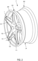
- the rigid wheel base 20 is a generally single-piece part, comprising a rigid central part 21 and a rigid peripheral part 23 rigidly connected by a plurality of spokes 26; each spoke 26 has two lateral faces 261 substantially parallel to each other and substantially parallel to a plane containing the axis of rotation of the wheel.
- the central part 21 comprises a fixing surface 22 on a hub, defining an axially inner side of the wheel.
- the peripheral portion 23 has a central zone forming the rim center 24.
- the floating seat wheel could also include flexible rim side portions mounted in various ways, such as in any of the examples given in the document WO2015/086662 , all things being equivalent with regard to the present invention which finds application as soon as the wheel comprises floating seats, whatever the embodiments of the flexible part of the wheel.
- the hubcap 1 has the general appearance of a star comprising a central edge 11 and an outer periphery 12.
- the central edge 11 is formed by a plurality of inner segments 111.
- the outer periphery 12 comprises a plurality of outer segments 121 forming arcs of circles contained on a circle circumscribed radially on the outside.
- the inner segments 111 of the central edge 11 comprise holes for receiving screws forming fixing elements on the rigid part of the wheel.
- the outer periphery 12 is arranged to cooperate with functional clearance J relative to said lateral rim part 251 (see figure 2 ).
- the wheel base 20 resembles a conventional light alloy wheel, but with a larger disc offset than usual. This is due to the fact that, on the seats, it is not a tire that is mounted directly, but the adapters that form the flexible rim side parts 251, 252.
- the offset is dimensioned so that the axially outer faces of the spokes 26 are substantially coplanar with the axially outer face of the flange 254.
- the outer periphery 12 comprises a plurality of outer segments 121 forming arcs of circles contained on the radially outer circumscribed circle.
- the outer periphery 12 has a shape of revolution almost parallel to, in the mounting position, the radially inner face of the lateral part of the rim 251 axially to the outside, facing the edge 254 (see figure 3 ).
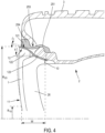
- the outer segments 121 are extended axially inwards by legs 123 (see figure 4 ).
- the legs are deformable; they have a sufficient length to accompany by their bending the radial displacement imposed on the outer periphery 12.
- the legs 123 have holes allowing the insertion of screws forming fixing elements on the rigid part of the wheel.
- the outer segments 121 are connected to the central edge 11 by at least one deformable arm 122, in this case in the example that the figure 1 illustrated, by two deformable arms 122, arranged to frame the two substantially parallel lateral faces 261 of the spokes 26 of the wheel.
- Two arms 122 are connected to each outer segment 121, on each side of each outer segment in the circumferential direction.
- the tab 123 extends each segment by the axially inner edge thereof.
- the central edge 11 comprises inner segments 111 each connected to two deformable arms 122, these coming from different outer segments 121, said two arms 122 being connected to the outer segment 121 which they connect on each side of said inner segment in the circumferential direction.
- FIG. 3 And 4 show a tire 3 mounted on a floating seat wheel 2 equipped with its hubcap 1.
- the reader will recognize all the elements previously described.
- the central edge is located at a radius R 1O and that the outer periphery 12 is located at a radius R 2O .
- the hubcap 1 conforms to the following arrangement: the circle R 1O is equal to 30% of R 2O .
- the hubcap is shown in continuous lines in its undeformed state, as it appears in figures 1 And 2 . It is also shown in the deformed state, in broken lines.
- the arms 122 are deformable, it is meant that they are made of a material that allows them to buckle without permanent deformation. Note that such deformation does not occur at each wheel revolution under normal conditions, but only when the tire undergoes a significant impact such as when exiting a pothole, and that in this case, only one sector of the wheel will undergo deformation, therefore normally one or possibly two pairs of arms 122.
- FIG. 5 is a radial section not included in the invention showing an alternative embodiment of a hubcap 1A having the general appearance of a truncated cone, the outer diameter of which is close to the seat diameter of the tire bead, and the inner diameter of which is close to the diameter of the central portion of the rim. Similar portions bear the same reference numerals, with the addition of the suffix “A”, which means that it is not useful to describe them again in full.
- the central edge 11A is radially quite close to the outer periphery 12A.
- the central edge 11A is interrupted to span the spokes 26.
- the hubcap 1A is intended to be fixed by screws 10A on the rigid part of the wheel 2 forming the axially outer edge on which a seat is arranged for mounting the flexible lateral part 251.
- the hubcap 1A conforms to the following arrangement: the outer periphery 12A is axially spaced from the closest 10A of the fixing elements on the wheel by a value W which is equal to 24% of R 2A .
- the outer periphery 12A is arranged to cooperate with functional clearance J relative to said lateral rim part 251.
- the hubcap 1A takes the shape shown in broken lines. Note that the circle R 1A is equal to 85% of R 2A .
- FIG. 6 is a radial section showing a second variant embodiment of a hubcap 1B whose radially outer portion resembles the embodiment described with the Figures 1 to 4 . Similar parts have the same reference numerals, with the addition of the suffix “B”, which means that it is not useful to describe them again in their entirety.
- Each outer segment 121B is connected, by its axially outer edge, to an arm 122B arranged axially outside the axially outer face of each spoke 26.
- the radially inner end of all the arms 122B forms the central edge 11B of the hubcap 1B, the arms 122B being deformable.
- the radially inner ends of the arms 122B form the central edge 11B of the hubcap 1B; they include holes for receiving screws 10B forming fixing elements on the rigid part of the wheel. It will be noted that in this implementation, the hubcap 1B also conforms to the following arrangement: the circle R 1B is equal to 33% of R 2B .
- the outer periphery 12B is arranged to cooperate with functional clearance J relative to said lateral rim portion 251.
- the hubcap 1B takes on the appearance shown in broken lines, with deformation of the lugs 123B and the arms 122B, the latter by axial displacement R which is all the greater the more one is at mid-radial height of the arms 122B (with isotropic material and constant section thereof).
- FIG. 7 is a radial section showing another variant embodiment of a hubcap 1C which is not included in the invention.
- This may take the form of a disk, pierced or not in the central part; it may also take the form of a set of arms 122C similar to the arms 122B.
- the similar parts bear the same numerical references, with the addition of the suffix “C”, which means that it is not useful to describe them again in full.
- the radially inner end of the set of arms 122C (or of the disk) forms the central edge 11C of the hubcap 1C.
- the arms 122C are deformable (or the disk is deformable).
- the central edge 11C has holes for receiving screws 10C forming fixing elements on the rigid part of the wheel.
- the hubcap 1C also conforms to the following arrangement: the circle R 1C is equal to 30% of R 2C . Note that, depending on the size of the wheel and the choice of materials, an appropriate range of values for R 1C is from 30% to 65% of R 2C .
- the outer periphery 12C (circumferentially continuous or not) is arranged so that, in the state free of any stress, hubcap 1C mounted on wheel 2, it is slightly offset axially relative to the rim 254, with functional clearance J.
- FIG 8 is another radial section not included in the invention showing a fourth alternative embodiment of a hubcap 1D according to the invention in which the outer periphery 12D of the hubcap 1D comprises fixing elements 10D, for example screws, on the floating part of the wheel, i.e. on the flange 254D, which comprises a corresponding female threaded part or any equivalent arrangement, depending on the fixing means used.
- Similar parts bear the same reference numbers, with the addition of the suffix "D", which means that it is not useful to describe them again in full.
- the hubcap 1D conforms to the following arrangement: the outer periphery 12D is axially spaced from the nearest 10D of the fixing elements on the wheel by a value WD which is equal to 24% of R 2D , WD being measured between the positive fixing points on one side on the rigid part of the wheel and on the other on the floating part of the wheel because this is what counts from a functional point of view to allow elastic deformations.
- the other elements are comparable to what has been described above (references to similar or identical parts being designated in the drawing by the same numbers this time bearing the suffix D and do not require further explanation.
- the invention lends itself to multiple variations; it opens up a new field of design for the use of wheels with floating rims; among possible and interesting variations, let us cite the possibility of integrating into the hubcap according to the invention an indicator of impact suffered beyond a certain threshold, which will result for example in a visible permanent deformation of a part of the hubcap, or a local breakage of the latter or the loss of the latter.
- the invention extends to an assembly comprising a hubcap 1, 1E according to the invention and a wheel 2 with a floating seat.
Landscapes
- Engineering & Computer Science (AREA)
- Mechanical Engineering (AREA)
- Tires In General (AREA)
Claims (6)
- Radkappe (1) eines Rades (2) mit schwimmendem Sitz für einen Reifen, wobei das Rad durch das Zusammenfügen einer starren Radbasis (20) und zweier flexibler seitlicher Felgenteile (251, 252), die einen Reifensitz (253), der über ein Horn (254) verfügt, umfassen, gebildet ist, wobei die Radkappe Folgendes umfasst:• einen zentralen Rand (11, 11B), der sich an einem Radius R1 befindet und Elemente zur Befestigung an dem Rad umfasst,• eine äußere Peripherie (12, 12B), die in einem Kreis mit einem Radius R2 eingeschrieben ist, dadurch gekennzeichnet, dass die äußere Peripherie (12, 12B) dazu eingerichtet ist, fähig zu sein, mit einem funktionellen Spiel "J" in Bezug auf ein seitliches Felgenteil (251) zusammenzuwirken, und dass:• die äußere Peripherie (12, 12B) eine Vielzahl von Außensegmenten (121) umfasst, die Kreisbögen bilden, die auf einem zu dem zentralen Rand (11, 11B) radial außenliegenden Umkreis enthalten sind, wobei die Außensegmente (121) eine rotationssymmetrische Form aufweisen, die fähig ist, sich in der Montageposition quasi parallel zu der radial innenliegenden Fläche des axial außenliegenden seitlichen Felgenteils (251), gegenüber dem Horn (254), zu befinden, wobei die Außensegmente (121) radial bewegbar sind,• die Außensegmente (121) durch mindestens einen verformbaren Arm (122) mit dem zentralen Rand (11) verbunden sind,• die Außensegmente (121) durch verformbare Laschen (123) axial nach innen verlängert sind, wobei die Laschen (123) Elemente zur Befestigung (10, 10B) an dem starren Teil des Rades umfassen,und dass der zentrale Rand (11, 11B) und die äußere Peripherie (12, 12B) mindestens einer der Ausgestaltungen entsprechen, die aus den folgenden zwei Ausgestaltungen gewählt werden:• die äußere Peripherie (12, 12B) ist von dem nächstgelegenen der Elemente zur Befestigung an dem Rad um einen Wert größer als 10 ö des Radius R2 axial beabstandet,• der Kreis mit dem Radius R1 beträgt maximal 90 ö des Radius R2.
- Radkappe nach Anspruch 1, für ein Rad mit schwimmendem Sitz, dessen starrer Teil eine Vielzahl von Speichen (26) umfasst, die den starren zentralen Teil (21) und den starren Peripherieteil (23) verbinden, wobei jede Speiche (26) zwei Seitenflächen (261) aufweist, die zueinander im Wesentlichen parallel und zu einer Ebene, die die Drehachse des Rades enthält, im Wesentlichen parallel sind, wobei:• die Außensegmente (121) mit dem zentralen Rand (11) durch zwei verformbare Arme (122) verbunden sind, die dazu eingerichtet sind, die zwei Seitenflächen (261) einzufassen, wobei zwei Arme (122) an das Außensegment (121), welches sie verbinden, auf jeder Seite des Außensegments in Umfangsrichtung angeschlossen sind, wobei die Lasche (123) das Segment an dessen axial innenliegendem Rand verlängert,• der zentrale Rand Innensegmente (111) umfasst, die jeweils mit zwei verformbaren Armen (122) verbunden sind, wobei diese zu unterschiedlichen Außensegmenten (121) gehören, wobei die zwei Arme (122) an das Außensegment (121), das sie verbinden, auf jeder Seite des Innensegments in Umfangsrichtung angeschlossen sind.
- Radkappe nach einem der Ansprüche 1 bis 2, wobei die Elemente zur Befestigung an dem starren Teil des Rades Schrauben sind.
- Radkappe nach einem der Ansprüche 1 bis 3, wobei der Kreis R1 maximal 75 ö von R2 beträgt.
- Radkappe nach einem der Ansprüche 4, wobei der Kreis R1 maximal 45 ö von R2 beträgt.
- Anordnung, die eine Radkappe (1) und ein Rad mit schwimmendem Sitz (2) umfasst, wobei der schwimmende Sitz dazu bestimmt ist, einen Reifen aufzunehmen, wobei das Rad (2) eine Drehachse aufweist, wobei das Rad (2) einen starren zentralen Teil (21) beinhaltet, der eine Montagefläche (22) umfasst, und einen starren Peripherieteil (23; 123B) beinhaltet, wobei der zentrale Teil mit dem Peripherieteil starr verbunden ist, wobei der Peripherieteil eine Felgenmitte (24) aufweist, wobei die Felgenmitte durch seitliche Felgenteile (251, 252) axial verlängert ist, wobei jedes seitliche Felgenteil einen Reifensitz (253) umfasst, der durch ein Horn (254) axial nach außen verlängert ist, wobei mindestens einer der Reifensitze (253) radial schwimmend ist, wobei die Radkappe einem der Ansprüche 1 bis 5 entspricht.
Applications Claiming Priority (2)
| Application Number | Priority Date | Filing Date | Title |
|---|---|---|---|
| FR1656593A FR3053633A3 (fr) | 2016-07-08 | 2016-07-08 | Enjoliveur flexible pour roue de vehicule a siege flottant, et roue a siege flottant equipee d'un enjoliveur flexible |
| PCT/FR2017/051816 WO2018007750A1 (fr) | 2016-07-08 | 2017-07-04 | Enjoliveur flexible pour roue de vehicule a siege flottant, et roue a siege flottant equipee d'un enjoliveur flexible |
Publications (3)
| Publication Number | Publication Date |
|---|---|
| EP3481644A1 EP3481644A1 (de) | 2019-05-15 |
| EP3481644B1 true EP3481644B1 (de) | 2025-01-08 |
| EP3481644C0 EP3481644C0 (de) | 2025-01-08 |
Family
ID=57539334
Family Applications (1)
| Application Number | Title | Priority Date | Filing Date |
|---|---|---|---|
| EP17745828.8A Active EP3481644B1 (de) | 2016-07-08 | 2017-07-04 | Flexible radkappe für ein fahrzeugrad mit einem schwebesitz und rad mit einem schwebesitz und einer flexiblen radkappe |
Country Status (5)
| Country | Link |
|---|---|
| US (1) | US11396204B2 (de) |
| EP (1) | EP3481644B1 (de) |
| CN (1) | CN109789724B (de) |
| FR (1) | FR3053633A3 (de) |
| WO (1) | WO2018007750A1 (de) |
Families Citing this family (5)
| Publication number | Priority date | Publication date | Assignee | Title |
|---|---|---|---|---|
| DE102018111492A1 (de) * | 2018-01-22 | 2019-07-25 | Gv Engineering Gmbh | Notlaufrad |
| WO2020142636A1 (en) * | 2019-01-02 | 2020-07-09 | Ravelo Michael | Adaptive wheel assembly with interchangeable decorative faces |
| USD1064996S1 (en) * | 2021-09-24 | 2025-03-04 | Ruben Rivera Clemente | Decorative wheel cover |
| USD1027789S1 (en) * | 2021-11-29 | 2024-05-21 | Citic Dicastal Co., Ltd. | Vehicle wheel |
| CN114670583A (zh) * | 2022-04-11 | 2022-06-28 | 浙江皓元实业有限公司 | 一种高强度防爆胎轮毂及加工平台 |
Citations (1)
| Publication number | Priority date | Publication date | Assignee | Title |
|---|---|---|---|---|
| DE102012207911A1 (de) * | 2012-05-11 | 2013-11-14 | Bayerische Motoren Werke Aktiengesellschaft | Abdeckung für ein Fahrzeugrad und Fahrzeugreifen dafür |
Family Cites Families (12)
| Publication number | Priority date | Publication date | Assignee | Title |
|---|---|---|---|---|
| US4268090A (en) * | 1980-06-09 | 1981-05-19 | William McCahill | Imbalance compensating vehicle wheel attachment |
| DE3328519C2 (de) | 1983-08-06 | 1985-11-14 | Messerschmitt-Bölkow-Blohm GmbH, 8012 Ottobrunn | Schallschutzschirm |
| GB8419384D0 (en) | 1984-07-30 | 1984-09-05 | Wolfrace Wheels Ltd | Dust covers |
| DE9204216U1 (de) | 1992-03-28 | 1992-05-07 | Emil Ziegler Metallwarenfabrik GmbH & Co KG, 7313 Reichenbach | Radkappenhalterung für Fahrzeuge, insbesondere Omnibusse |
| DE4301778C2 (de) | 1993-01-23 | 1998-07-02 | Opel Adam Ag | Geräuschdämmende Radabdeckung |
| TW245691B (de) * | 1993-07-28 | 1995-04-21 | Janus Jonny | |
| JP3248805B2 (ja) | 1994-04-07 | 2002-01-21 | 株式会社東海理化電機製作所 | 自動車用ホイールキャップ |
| BE1012250A3 (nl) | 1998-10-27 | 2000-08-01 | Wheeltech Bvba | Hulpstuk voor licht metalen wielvelgen. |
| US20090066151A1 (en) * | 2007-09-06 | 2009-03-12 | Diko Sulahian | Adaptable wheel assembly |
| FR3014362B1 (fr) | 2013-12-11 | 2017-03-17 | Michelin & Cie | Ensemble roulant perfectionne |
| FR3026051B1 (fr) | 2014-09-24 | 2016-11-04 | Michelin & Cie | Adaptateur pour ensemble roulant et ensemble roulant le comprenant |
| US9421819B2 (en) * | 2014-11-24 | 2016-08-23 | Consolidated Metco, Inc. | Vehicle wheel hubcap with vent |
-
2016
- 2016-07-08 FR FR1656593A patent/FR3053633A3/fr active Pending
-
2017
- 2017-07-04 EP EP17745828.8A patent/EP3481644B1/de active Active
- 2017-07-04 WO PCT/FR2017/051816 patent/WO2018007750A1/fr not_active Ceased
- 2017-07-04 US US16/316,206 patent/US11396204B2/en active Active
- 2017-07-04 CN CN201780041971.2A patent/CN109789724B/zh active Active
Patent Citations (1)
| Publication number | Priority date | Publication date | Assignee | Title |
|---|---|---|---|---|
| DE102012207911A1 (de) * | 2012-05-11 | 2013-11-14 | Bayerische Motoren Werke Aktiengesellschaft | Abdeckung für ein Fahrzeugrad und Fahrzeugreifen dafür |
Also Published As
| Publication number | Publication date |
|---|---|
| WO2018007750A1 (fr) | 2018-01-11 |
| FR3053633A3 (fr) | 2018-01-12 |
| CN109789724B (zh) | 2023-01-13 |
| US20210283947A1 (en) | 2021-09-16 |
| CN109789724A (zh) | 2019-05-21 |
| US11396204B2 (en) | 2022-07-26 |
| EP3481644A1 (de) | 2019-05-15 |
| EP3481644C0 (de) | 2025-01-08 |
Similar Documents
| Publication | Publication Date | Title |
|---|---|---|
| EP3481644B1 (de) | Flexible radkappe für ein fahrzeugrad mit einem schwebesitz und rad mit einem schwebesitz und einer flexiblen radkappe | |
| EP3481650B1 (de) | Ringverzierung für rad mit schwimmendem reifensitz | |
| EP0755807B1 (de) | Rad für Nutzfahrzeuge mit aussenliegendem Ventil | |
| EP3645306B1 (de) | Radfelge mit optimierter felgenhornform | |
| EP1910099A1 (de) | Fahrzeugrad mit sitzen ungleichen durchmessers und aus einem rad und einem stützelement bestehende anordnung | |
| FR3054479A3 (fr) | Adaptateur et jante pour ensemble roulant, ensemble forme par l'adaptateur et la jante, et ensemble roulant les comprenant | |
| EP3523141B1 (de) | Reifen für fahrzeug zum tragen schwerer lasten | |
| FR3043946A1 (fr) | Enjoliveur personnalise pour roue structurelle de vehicule | |
| FR3078922A1 (fr) | Roue structurelle de vehicule a effet aerodynamique et vehicule comprenant une telle roue | |
| EP3802151B1 (de) | Flexibler adapter und felgenanordnung für eine rollanordnung | |
| US20200047549A1 (en) | Automobile wheel | |
| FR3057206B1 (fr) | Roue de vehicule ferroviaire et vehicule ferroviaire equipe d'une telle roue | |
| EP1187730A1 (de) | Rad mit schalldämpfung | |
| EP3581824B1 (de) | Scheibenbremssystem und luftfahrzeug | |
| EP2934907B1 (de) | Anordnung von rad und radgehäuse für einen sammelwagen | |
| EP3628514B1 (de) | Plastisch deformierbare konsole zur befestigung eines kraftfahrzeugrades | |
| WO2019020898A1 (fr) | Roue pour le montage d'un dispositif de type pneumatique pour vehicule | |
| WO2019238278A1 (fr) | Jante pour roue de véhicule | |
| WO2006010681A1 (fr) | Jante de véhicule destinée au montage d'un pneumatique et d'un appui de soutien | |
| WO2023110498A1 (fr) | Pneumatique comportant un flanc a stylisme ameliore | |
| FR3079169A1 (fr) | Procede de rigidification d'une coupelle inferieure d'une butee de suspension de vehicule automobile | |
| FR2881989A1 (fr) | Jante de vehicule destinee au montage d'un pneumatique et d'un appui de soutien | |
| BE332121A (de) | ||
| BE335441A (de) | ||
| BE518371A (de) |
Legal Events
| Date | Code | Title | Description |
|---|---|---|---|
| STAA | Information on the status of an ep patent application or granted ep patent |
Free format text: STATUS: UNKNOWN |
|
| STAA | Information on the status of an ep patent application or granted ep patent |
Free format text: STATUS: THE INTERNATIONAL PUBLICATION HAS BEEN MADE |
|
| PUAI | Public reference made under article 153(3) epc to a published international application that has entered the european phase |
Free format text: ORIGINAL CODE: 0009012 |
|
| STAA | Information on the status of an ep patent application or granted ep patent |
Free format text: STATUS: REQUEST FOR EXAMINATION WAS MADE |
|
| 17P | Request for examination filed |
Effective date: 20190208 |
|
| AK | Designated contracting states |
Kind code of ref document: A1 Designated state(s): AL AT BE BG CH CY CZ DE DK EE ES FI FR GB GR HR HU IE IS IT LI LT LU LV MC MK MT NL NO PL PT RO RS SE SI SK SM TR |
|
| AX | Request for extension of the european patent |
Extension state: BA ME |
|
| RIN1 | Information on inventor provided before grant (corrected) |
Inventor name: WALSER, DANIEL Inventor name: EBEL, BENJAMIN EDWARD Inventor name: VITS, JOHAN Inventor name: DUNING, RALF |
|
| DAV | Request for validation of the european patent (deleted) | ||
| DAX | Request for extension of the european patent (deleted) | ||
| STAA | Information on the status of an ep patent application or granted ep patent |
Free format text: STATUS: EXAMINATION IS IN PROGRESS |
|
| 17Q | First examination report despatched |
Effective date: 20220303 |
|
| RAP1 | Party data changed (applicant data changed or rights of an application transferred) |
Owner name: MAXION WHEELS HOLDING GMBH |
|
| GRAP | Despatch of communication of intention to grant a patent |
Free format text: ORIGINAL CODE: EPIDOSNIGR1 |
|
| STAA | Information on the status of an ep patent application or granted ep patent |
Free format text: STATUS: GRANT OF PATENT IS INTENDED |
|
| INTG | Intention to grant announced |
Effective date: 20240806 |
|
| GRAS | Grant fee paid |
Free format text: ORIGINAL CODE: EPIDOSNIGR3 |
|
| GRAA | (expected) grant |
Free format text: ORIGINAL CODE: 0009210 |
|
| STAA | Information on the status of an ep patent application or granted ep patent |
Free format text: STATUS: THE PATENT HAS BEEN GRANTED |
|
| AK | Designated contracting states |
Kind code of ref document: B1 Designated state(s): AL AT BE BG CH CY CZ DE DK EE ES FI FR GB GR HR HU IE IS IT LI LT LU LV MC MK MT NL NO PL PT RO RS SE SI SK SM TR |
|
| REG | Reference to a national code |
Ref country code: GB Ref legal event code: FG4D Free format text: NOT ENGLISH |
|
| REG | Reference to a national code |
Ref country code: CH Ref legal event code: EP |
|
| REG | Reference to a national code |
Ref country code: DE Ref legal event code: R096 Ref document number: 602017087240 Country of ref document: DE |
|
| REG | Reference to a national code |
Ref country code: IE Ref legal event code: FG4D Free format text: LANGUAGE OF EP DOCUMENT: FRENCH |
|
| U01 | Request for unitary effect filed |
Effective date: 20250129 |
|
| U07 | Unitary effect registered |
Designated state(s): AT BE BG DE DK EE FI FR IT LT LU LV MT NL PT RO SE SI Effective date: 20250205 |
|
| PG25 | Lapsed in a contracting state [announced via postgrant information from national office to epo] |
Ref country code: RS Free format text: LAPSE BECAUSE OF FAILURE TO SUBMIT A TRANSLATION OF THE DESCRIPTION OR TO PAY THE FEE WITHIN THE PRESCRIBED TIME-LIMIT Effective date: 20250408 |
|
| PG25 | Lapsed in a contracting state [announced via postgrant information from national office to epo] |
Ref country code: PL Free format text: LAPSE BECAUSE OF FAILURE TO SUBMIT A TRANSLATION OF THE DESCRIPTION OR TO PAY THE FEE WITHIN THE PRESCRIBED TIME-LIMIT Effective date: 20250108 |
|
| PG25 | Lapsed in a contracting state [announced via postgrant information from national office to epo] |
Ref country code: ES Free format text: LAPSE BECAUSE OF FAILURE TO SUBMIT A TRANSLATION OF THE DESCRIPTION OR TO PAY THE FEE WITHIN THE PRESCRIBED TIME-LIMIT Effective date: 20250108 |
|
| PG25 | Lapsed in a contracting state [announced via postgrant information from national office to epo] |
Ref country code: IS Free format text: LAPSE BECAUSE OF FAILURE TO SUBMIT A TRANSLATION OF THE DESCRIPTION OR TO PAY THE FEE WITHIN THE PRESCRIBED TIME-LIMIT Effective date: 20250508 Ref country code: NO Free format text: LAPSE BECAUSE OF FAILURE TO SUBMIT A TRANSLATION OF THE DESCRIPTION OR TO PAY THE FEE WITHIN THE PRESCRIBED TIME-LIMIT Effective date: 20250408 |
|
| PG25 | Lapsed in a contracting state [announced via postgrant information from national office to epo] |
Ref country code: HR Free format text: LAPSE BECAUSE OF FAILURE TO SUBMIT A TRANSLATION OF THE DESCRIPTION OR TO PAY THE FEE WITHIN THE PRESCRIBED TIME-LIMIT Effective date: 20250108 |
|
| PG25 | Lapsed in a contracting state [announced via postgrant information from national office to epo] |
Ref country code: GR Free format text: LAPSE BECAUSE OF FAILURE TO SUBMIT A TRANSLATION OF THE DESCRIPTION OR TO PAY THE FEE WITHIN THE PRESCRIBED TIME-LIMIT Effective date: 20250409 |
|
| U20 | Renewal fee for the european patent with unitary effect paid |
Year of fee payment: 9 Effective date: 20250728 |
|
| PG25 | Lapsed in a contracting state [announced via postgrant information from national office to epo] |
Ref country code: SM Free format text: LAPSE BECAUSE OF FAILURE TO SUBMIT A TRANSLATION OF THE DESCRIPTION OR TO PAY THE FEE WITHIN THE PRESCRIBED TIME-LIMIT Effective date: 20250108 |
|
| PG25 | Lapsed in a contracting state [announced via postgrant information from national office to epo] |
Ref country code: CZ Free format text: LAPSE BECAUSE OF FAILURE TO SUBMIT A TRANSLATION OF THE DESCRIPTION OR TO PAY THE FEE WITHIN THE PRESCRIBED TIME-LIMIT Effective date: 20250108 |
|
| PG25 | Lapsed in a contracting state [announced via postgrant information from national office to epo] |
Ref country code: SK Free format text: LAPSE BECAUSE OF FAILURE TO SUBMIT A TRANSLATION OF THE DESCRIPTION OR TO PAY THE FEE WITHIN THE PRESCRIBED TIME-LIMIT Effective date: 20250108 |
|
| PLBE | No opposition filed within time limit |
Free format text: ORIGINAL CODE: 0009261 |
|
| STAA | Information on the status of an ep patent application or granted ep patent |
Free format text: STATUS: NO OPPOSITION FILED WITHIN TIME LIMIT |