EP3480994B1 - Verfahren zum empfangen eines downlink-steuerkanals und vorrichtung dafür - Google Patents
Verfahren zum empfangen eines downlink-steuerkanals und vorrichtung dafür Download PDFInfo
- Publication number
- EP3480994B1 EP3480994B1 EP18790941.1A EP18790941A EP3480994B1 EP 3480994 B1 EP3480994 B1 EP 3480994B1 EP 18790941 A EP18790941 A EP 18790941A EP 3480994 B1 EP3480994 B1 EP 3480994B1
- Authority
- EP
- European Patent Office
- Prior art keywords
- reg
- information
- matrix
- cce
- coreset
- Prior art date
- Legal status (The legal status is an assumption and is not a legal conclusion. Google has not performed a legal analysis and makes no representation as to the accuracy of the status listed.)
- Active
Links
Images


Classifications
-
- H—ELECTRICITY
- H04—ELECTRIC COMMUNICATION TECHNIQUE
- H04L—TRANSMISSION OF DIGITAL INFORMATION, e.g. TELEGRAPHIC COMMUNICATION
- H04L1/00—Arrangements for detecting or preventing errors in the information received
-
- H—ELECTRICITY
- H04—ELECTRIC COMMUNICATION TECHNIQUE
- H04L—TRANSMISSION OF DIGITAL INFORMATION, e.g. TELEGRAPHIC COMMUNICATION
- H04L1/00—Arrangements for detecting or preventing errors in the information received
- H04L1/004—Arrangements for detecting or preventing errors in the information received by using forward error control
- H04L1/0056—Systems characterized by the type of code used
- H04L1/0071—Use of interleaving
-
- H—ELECTRICITY
- H04—ELECTRIC COMMUNICATION TECHNIQUE
- H04L—TRANSMISSION OF DIGITAL INFORMATION, e.g. TELEGRAPHIC COMMUNICATION
- H04L5/00—Arrangements affording multiple use of the transmission path
-
- H—ELECTRICITY
- H04—ELECTRIC COMMUNICATION TECHNIQUE
- H04L—TRANSMISSION OF DIGITAL INFORMATION, e.g. TELEGRAPHIC COMMUNICATION
- H04L5/00—Arrangements affording multiple use of the transmission path
- H04L5/0001—Arrangements for dividing the transmission path
- H04L5/0003—Two-dimensional division
- H04L5/0005—Time-frequency
- H04L5/0007—Time-frequency the frequencies being orthogonal, e.g. OFDM(A) or DMT
-
- H—ELECTRICITY
- H04—ELECTRIC COMMUNICATION TECHNIQUE
- H04L—TRANSMISSION OF DIGITAL INFORMATION, e.g. TELEGRAPHIC COMMUNICATION
- H04L5/00—Arrangements affording multiple use of the transmission path
- H04L5/003—Arrangements for allocating sub-channels of the transmission path
- H04L5/0048—Allocation of pilot signals, i.e. of signals known to the receiver
-
- H—ELECTRICITY
- H04—ELECTRIC COMMUNICATION TECHNIQUE
- H04L—TRANSMISSION OF DIGITAL INFORMATION, e.g. TELEGRAPHIC COMMUNICATION
- H04L5/00—Arrangements affording multiple use of the transmission path
- H04L5/003—Arrangements for allocating sub-channels of the transmission path
- H04L5/0053—Allocation of signalling, i.e. of overhead other than pilot signals
-
- H—ELECTRICITY
- H04—ELECTRIC COMMUNICATION TECHNIQUE
- H04L—TRANSMISSION OF DIGITAL INFORMATION, e.g. TELEGRAPHIC COMMUNICATION
- H04L5/00—Arrangements affording multiple use of the transmission path
- H04L5/0091—Signalling for the administration of the divided path, e.g. signalling of configuration information
- H04L5/0094—Indication of how sub-channels of the path are allocated
-
- H—ELECTRICITY
- H04—ELECTRIC COMMUNICATION TECHNIQUE
- H04W—WIRELESS COMMUNICATION NETWORKS
- H04W72/00—Local resource management
- H04W72/20—Control channels or signalling for resource management
- H04W72/23—Control channels or signalling for resource management in the downlink direction of a wireless link, i.e. towards a terminal
-
- H—ELECTRICITY
- H04—ELECTRIC COMMUNICATION TECHNIQUE
- H04L—TRANSMISSION OF DIGITAL INFORMATION, e.g. TELEGRAPHIC COMMUNICATION
- H04L5/00—Arrangements affording multiple use of the transmission path
- H04L5/0091—Signalling for the administration of the divided path, e.g. signalling of configuration information
- H04L5/0092—Indication of how the channel is divided
Definitions
- the present invention relates to a method and apparatus for receiving a downlink control channel and, more particularly, to a method and apparatus for receiving a plurality of resource element groups (REGs) included in a control channel element (CCE) configuring a downlink control channel in a state of being mapped to one or more physical resources.
- REGs resource element groups
- CCE control channel element
- next-generation 5G system As more and more communication apparatuses require more communication traffic, a next-generation 5G system, which is further improved as compared to an existing LTE system, is required.
- NewRAT Next-generation 5G system
- communication scenarios are classified into Enhanced Mobile BroadBand (eMBB), Ultra-reliability and low-latency communication (URLLC), and Massive Machine-Type Communications (mMTC).
- eMBB Enhanced Mobile BroadBand
- URLLC Ultra-reliability and low-latency communication
- mMTC Massive Machine-Type Communications
- the eMBB is a next-generation mobile communication scenario having high spectrum efficiency, high user experienced data rate, high peak data rate, etc.
- the URLLC is a next-generation mobile communication scenario having ultra-high reliability, ultra-low latency, ultra-high availability, etc. (e.g., V2X, Emergency Service, Remote Control)
- the mMTC is a next-generation mobile communication scenario having low cost, low energy, short packets, massive connectivity, etc. (e.g., IoT).
- the 3GPP Draft No. R1-1704204 entitled “Discussion on NR-PDCCH structure ", discusses the mapping of REGs to a CCE in the context of New Radio Physical Downlink Control Channel (NR-PDCCH) structures.
- NR-PDCCH New Radio Physical Downlink Control Channel
- R1-1705175 entitled “Configuration of CORSET and Search space design”
- the 3GPP Draft No. R1-1706318, entitled “WF on REG to CCE Mapping for NR-PDCCH” discusses configuring the mapping of REGs to a CCE carrying NR-PDCCH.
- International application publication No. WO 2013/100623 Al discusses a method and apparatus for transmitting and receiving downlink control information.
- the present invention provides a method and apparatus for receiving a downlink control channel.
- the object of the present invention can be achieved by providing a method of receiving a downlink control channel at a user equipment (UE) in a wireless communication system as set forth in the appended claims.
- UE user equipment
- UE user equipment
- BS base station
- LTE Long Term Evolution
- LTE-A LTE-Advanced
- BS Base Station
- RRH Remote Radio Head
- eNB evolved Node B
- RP Reception Point
- FIG. 1 illustrates control-plane and user-plane protocol stacks in a radio interface protocol architecture conforming to a 3GPP wireless access network standard between a User Equipment (UE) and an Evolved UMTS Terrestrial Radio Access Network (E-UTRAN).
- the control plane is a path in which the UE and the E-UTRAN transmit control messages to manage calls
- the user plane is a path in which data generated from an application layer, for example, voice data or Internet packet data is transmitted.
- a PHYsical (PHY) layer at Layer 1 (L1) provides information transfer service to its higher layer, a Medium Access Control (MAC) layer.
- the PHY layer is connected to the MAC layer via transport channels.
- the transport channels deliver data between the MAC layer and the PHY layer.
- Data is transmitted on physical channels between the PHY layers of a transmitter and a receiver.
- the physical channels use time and frequency as radio resources. Specifically, the physical channels are modulated in Orthogonal Frequency Division Multiple Access (OFDMA) for Downlink (DL) and in Single Carrier Frequency Division Multiple Access (SC-FDMA) for Uplink (UL).
- OFDMA Orthogonal Frequency Division Multiple Access
- SC-FDMA Single Carrier Frequency Division Multiple Access
- the MAC layer at Layer 2 provides service to its higher layer, a Radio Link Control (RLC) layer via logical channels.
- the RLC layer at L2 supports reliable data transmission.
- RLC functionality may be implemented in a function block of the MAC layer.
- a Packet Data Convergence Protocol (PDCP) layer at L2 performs header compression to reduce the amount of unnecessary control information and thus efficiently transmit Internet Protocol (IP) packets such as IP version 4 (IPv4) or IP version 6 (IPv6) packets via an air interface having a narrow bandwidth.
- IP Internet Protocol
- IPv4 IP version 4
- IPv6 IP version 6
- a Radio Resource Control (RRC) layer at the lowest part of Layer 3 (or L3) is defined only on the control plane.
- the RRC layer controls logical channels, transport channels, and physical channels in relation to configuration, reconfiguration, and release of radio bearers.
- a radio bearer refers to a service provided at L2, for data transmission between the UE and the E-UTRAN.
- the RRC layers of the UE and the E-UTRAN exchange RRC messages with each other. If an RRC connection is established between the UE and the E-UTRAN, the UE is in RRC Connected mode and otherwise, the UE is in RRC Idle mode.
- a Non-Access Stratum (NAS) layer above the RRC layer performs functions including session management and mobility management.
- NAS Non-Access Stratum
- DL transport channels used to deliver data from the E-UTRAN to UEs include a Broadcast Channel (BCH) carrying system information, a Paging Channel (PCH) carrying a paging message, and a Shared Channel (SCH) carrying user traffic or a control message.
- BCH Broadcast Channel
- PCH Paging Channel
- SCH Shared Channel
- DL multicast traffic or control messages or DL broadcast traffic or control messages may be transmitted on a DL SCH or a separately defined DL Multicast Channel (MCH).
- UL transport channels used to deliver data from a UE to the E-UTRAN include a Random Access Channel (RACH) carrying an initial control message and a UL SCH carrying user traffic or a control message.
- RACH Random Access Channel
- Logical channels that are defined above transport channels and mapped to the transport channels include a Broadcast Control Channel (BCCH), a Paging Control Channel (PCCH), a Common Control Channel (CCCH), a Multicast Control Channel (MCCH), a Multicast Traffic Channel (MTCH), etc.
- BCCH Broadcast Control Channel
- PCCH Paging Control Channel
- CCCH Common Control Channel
- MCCH Multicast Control Channel
- MTCH Multicast Traffic Channel
- FIG. 2 illustrates physical channels and a general method for transmitting signals on the physical channels in the 3GPP system.
- the UE when a UE is powered on or enters a new cell, the UE performs initial cell search (S201).
- the initial cell search involves acquisition of synchronization to an eNB. Specifically, the UE synchronizes its timing to the eNB and acquires a cell Identifier (ID) and other information by receiving a Primary Synchronization Channel (P-SCH) and a Secondary Synchronization Channel (S-SCH) from the eNB. Then the UE may acquire information broadcast in the cell by receiving a Physical Broadcast Channel (PBCH) from the eNB.
- PBCH Physical Broadcast Channel
- the UE may monitor a DL channel state by receiving a DownLink Reference Signal (DL RS).
- DL RS DownLink Reference Signal
- the UE may acquire detailed system information by receiving a Physical Downlink Control Channel (PDCCH) and receiving a Physical Downlink Shared Channel (PDSCH) based on information included in the PDCCH (S202).
- PDCCH Physical Downlink Control Channel
- PDSCH Physical Downlink Shared Channel
- the UE may perform a random access procedure with the eNB (S203 to S206).
- the UE may transmit a predetermined sequence as a preamble on a Physical Random Access Channel (PRACH) (S203 and S205) and may receive a response message to the preamble on a PDCCH and a PDSCH associated with the PDCCH (S204 and S206).
- PRACH Physical Random Access Channel
- the UE may additionally perform a contention resolution procedure.
- the UE may receive a PDCCH and/or a PDSCH from the eNB (S207) and transmit a Physical Uplink Shared Channel (PUSCH) and/or a Physical Uplink Control Channel (PUCCH) to the eNB (S208), which is a general DL and UL signal transmission procedure.
- the UE receives Downlink Control Information (DCI) on a PDCCH.
- DCI Downlink Control Information
- the DCI includes control information such as resource allocation information for the UE. Different DCI formats are defined according to different usages of DCI.
- Control information that the UE transmits to the eNB on the UL or receives from the eNB on the DL includes a DL/UL ACKnowledgment/Negative ACKnowledgment (ACK/NACK) signal, a Channel Quality Indicator (CQI), a Precoding Matrix Index (PMI), a Rank Indicator (RI), etc.
- ACK/NACK DL/UL ACKnowledgment/Negative ACKnowledgment
- CQI Channel Quality Indicator
- PMI Precoding Matrix Index
- RI Rank Indicator
- the UE may transmit control information such as a CQI, a PMI, an RI, etc. on a PUSCH and/or a PUCCH.
- FIG. 3 illustrates a structure of a radio frame used in the LTE system.
- a radio frame is 10ms (327200xTs) long and divided into 10 equal-sized subframes.
- Each subframe is 1ms long and further divided into two slots.
- Each time slot is 0.5ms (15360xTs) long.
- a slot includes a plurality of Orthogonal Frequency Division Multiplexing (OFDM) symbols or SC-FDMA symbols in the time domain by a plurality of Resource Blocks (RBs) in the frequency domain.
- OFDM Orthogonal Frequency Division Multiplexing
- RBs Resource Blocks
- one RB includes 12 subcarriers by 7 (or 6) OFDM symbols.
- a unit time during which data is transmitted is defined as a Transmission Time Interval (TTI).
- TTI may be defined in units of one or more subframes.
- the above-described radio frame structure is purely exemplary and thus the number of subframes in a radio frame, the number of slots in a subframe, or the number of OFDM symbols in a slot may vary.
- FIG. 4 illustrates exemplary control channels included in a control region of a subframe in a DL radio frame.
- a subframe includes 14 OFDM symbols.
- the first one to three OFDM symbols of a subframe are used for a control region and the other 13 to 11 OFDM symbols are used for a data region according to a subframe configuration.
- reference characters R1 to R4 denote RSs or pilot signals for antenna 0 to antenna 3.
- RSs are allocated in a predetermined pattern in a subframe irrespective of the control region and the data region.
- a control channel is allocated to non-RS resources in the control region and a traffic channel is also allocated to non-RS resources in the data region.
- Control channels allocated to the control region include a Physical Control Format Indicator Channel (PCFICH), a Physical Hybrid-ARQ Indicator Channel (PHICH), a Physical Downlink Control Channel (PDCCH), etc.
- PCFICH Physical Control Format Indicator Channel
- PHICH Physical Hybrid-ARQ Indicator Channel
- PDCCH Physical Downlink Control Channel
- the PCFICH is a physical control format indicator channel carrying information about the number of OFDM symbols used for PDCCHs in each subframe.
- the PCFICH is located in the first OFDM symbol of a subframe and configured with priority over the PHICH and the PDCCH.
- the PCFICH includes 4 Resource Element Groups (REGs), each REG being distributed to the control region based on a cell Identity (ID).
- One REG includes 4 Resource Elements (REs).
- An RE is a minimum physical resource defined by one subcarrier by one OFDM symbol.
- the PCFICH is set to 1 to 3 or 2 to 4 according to a bandwidth.
- the PCFICH is modulated in Quadrature Phase Shift Keying (QPSK).
- QPSK Quadrature Phase Shift Keying
- the PHICH is a physical Hybrid-Automatic Repeat and request (HARQ) indicator channel carrying an HARQ ACK/NACK for a UL transmission. That is, the PHICH is a channel that delivers DL ACK/NACK information for UL HARQ.
- the PHICH includes one REG and is scrambled cell-specifically.
- An ACK/NACK is indicated in one bit and modulated in Binary Phase Shift Keying (BPSK).
- BPSK Binary Phase Shift Keying
- the modulated ACK/NACK is spread with a Spreading Factor (SF) of 2 or 4.
- SF Spreading Factor
- a plurality of PHICHs mapped to the same resources form a PHICH group. The number of PHICHs multiplexed into a PHICH group is determined according to the number of spreading codes.
- a PHICH (group) is repeated three times to obtain a diversity gain in the frequency domain and/or the time domain.
- the PDCCH is a physical DL control channel allocated to the first n OFDM symbols of a subframe.
- n is 1 or a larger integer indicated by the PCFICH.
- the PDCCH occupies one or more CCEs.
- the PDCCH carries resource allocation information about transport channels, PCH and DL-SCH, a UL scheduling grant, and HARQ information to each UE or UE group.
- the PCH and the DL-SCH are transmitted on a PDSCH. Therefore, an eNB and a UE transmit and receive data usually on the PDSCH, except for specific control information or specific service data.
- Information indicating one or more UEs to receive PDSCH data and information indicating how the UEs are supposed to receive and decode the PDSCH data are delivered on a PDCCH.
- CRC Cyclic Redundancy Check
- RNTI Radio Network Temporary Identity
- information about data transmitted in radio resources e.g. at a frequency position
- transport format information e.g. a transport block size, a modulation scheme, coding information, etc.
- FIG. 5 illustrates resource units used to configure a downlink control channel in LTE.
- FIG. 5(a) shows a case in which the number of transmit (Tx) antennas is 1 or 2 and
- FIG. 5(b) shows a case in which the number of Tx antenna is 4.
- a different RS pattern is used according to the number of Tx antennas, REs are configured for a DL control channel in the same manner.
- a basic resource unit of a DL control channel is an REG.
- the REG includes four contiguous REs except for REs carrying RSs. REGs are marked with bold lines in FIG. 5 .
- a PCFICH and a PHICH include 4 REGs and 3 REGs, respectively.
- a PDCCH is configured in units of a control channel element (CCE), each CCE including 9 REGs.
- CCE control channel element
- the UE To determine whether a PDCCH including L CCEs is transmitted to a UE, the UE is configured to monitor M (L) ( ⁇ L) CCEs that are arranged contiguously or according to a predetermined rule. L that the UE should consider for PDCCH reception may be a plural value. CCE sets that the UE should monitor to receive a PDCCH are referred to as a search space. For example, LTE defines search spaces as illustrated in Table 1. [Table 1] Search space S k L Number of PDCCH candidates M ( L ) Type Aggregation level L Size [in CCEs] UE-specific 1 6 6 2 12 6 4 8 2 8 16 2 Common 4 16 4 8 16 2
- L is a CCE aggregation level, that is, the number of CCEs in a PDCCH
- S k (L) is a search space with CCE aggregation level L
- M (L) is the number of candidate PDCCHs to be monitored in the search space with CCE aggregation level L.
- Search spaces are classified into a UE-specific search space accessible only by a specific UE and a common search space accessible by all UEs within a cell.
- a UE monitors common search spaces with CCE aggregation levels 4 and 8 and UE-specific search spaces with CCE aggregation levels 1, 2, 4, and 8.
- a common search space and a UE-specific search space may overlap each other.
- PDCCH search space hashing For each CCE aggregation level, the position of the first CCE (a CCE having the smallest index) of a PDCCH search space allocated to a UE changes every subframe. This is called PDCCH search space hashing.
- a CCE may be distributed across a system band. More specifically, a plurality of logically contiguous CCEs may be input to an interleaver and the interleaver may permute the sequence of the input CCEs on an REG basis. Accordingly, the time/frequency resources of one CCE are distributed physically across the total time/frequency region of the control region of a subframe. As a control channel is configured in units of a CCE but interleaved in units of an REG, frequency diversity gain and interference randomization gain may be maximized.
- FIG. 6 illustrates a structure of a UL subframe in the LTE system.
- a UL subframe may be divided into a control region and a data region.
- a Physical Uplink Control Channel (PUCCH) including Uplink Control Information (UCI) is allocated to the control region and a Physical uplink Shared Channel (PUSCH) including user data is allocated to the data region.
- the middle of the subframe is allocated to the PUSCH, while both sides of the data region in the frequency domain are allocated to the PUCCH.
- Control information transmitted on the PUCCH may include an HARQ ACK/NACK, a CQI representing a downlink channel state, an RI for Multiple Input Multiple Output (MIMO), a Scheduling Request (SR) requesting UL resource allocation.
- MIMO Multiple Input Multiple Output
- SR Scheduling Request
- each of an eNB and a UE may perform beamforming based on CSI to obtain the multiplexing gain of MIMO antennas.
- the eNB may command the UE to feed back CSI on a downlink signal by allocating a PUCCH(Physical Uplink Control CHannel) or a PUSCH(Physical Uplink Shared CHannel) to the UE.
- the CSI is largely classified into three information types, RI (Rank Indicator), PMI (Precoding Matrix), and CQI (Channel Quality Indication).
- RI Rank Indicator
- PMI Precoding Matrix
- CQI Channel Quality Indication
- the PMI is a value obtained by reflecting spatial characteristics of a channel, and indicates a precoding matrix index of an eNB, which is preferred by the UE based on a metric such as signal to interference and noise ratio (SINR).
- SINR signal to interference and noise ratio
- the CQI is a value indicating channel strength, and generally means a reception SINR that may be obtained by the eNB when the PMI is used.
- the eNB may configure a plurality of CSI processes for the UE, and may be reported CSI for each of the CSI processes.
- the CSI process includes CSI-RS resource for specifying signal quality and CSI-IM (interference measurement) resource, that is, IMR (interference measurement resource) for interference measurement.
- a wavelength becomes short in the field of Millimeter Wave (mmW)
- a plurality of antenna elements may be installed in the same area.
- a wavelength is 1cm in a band of 30GHz
- a total of 64(8x8) antenna elements of a 2D array may be installed in a panel of 4 by 4 cm at an interval of 0.5 lambda(wavelength). Therefore, a recent trend in the field of mmW attempts to increase coverage or throughput by enhancing BF (beamforming) gain using a plurality of antenna elements.
- TXRU transceiver unit
- independent beamforming may be performed for each frequency resource.
- a problem occurs in that effectiveness is deteriorated in view of cost when TXRU is provided for all of 100 antenna elements. Therefore, a scheme is considered, in which a plurality of antenna elements are mapped into one TXRU and a beam direction is controlled by an analog phase shifter. Since this analog beamforming scheme may make only one beam direction in a full band, a problem occurs in that frequency selective beamforming is not available.
- a hybrid BF having B TXRUs smaller than Q antenna elements may be considered.
- the number of beam directions that enable simultaneous transmission is limited to B or less.
- FIG. 7 illustrates examples of a connection scheme between TXRUs and antenna elements.
- FIG. 7 illustrates that TXRU is connected to a sub-array. In this case, the antenna elements are connected to only one TXRU. Unlike (a) of FIG. 7 , (b) of FIG. 7 illustrates that TXRU is connected to all antenna elements. In this case, the antenna elements are connected to all TXRUs.
- W indicates a phase vector multiplied by an analog phase shifter. That is, a direction of analog beamforming is determined by W.
- mapping between CSI-RS antenna ports and TXRUs may be 1-to-1 or 1-to-many.
- next generation communication As more communication devices require greater communication capacity, the need of mobile broadband communication more advanced than the conventional RAT (radio access technology) has been issued. Also, massive MTC (Machine Type Communications) technology that provides various services anywhere and at any time by connecting a plurality of devices and things is one of main issues which will be considered in next generation communication. Furthermore, a communication system design considering service/UE susceptible to reliability and latency has been discussed. Considering this status, the introduction of the next generation RAT has been discussed, and the next generation RAT will be referred to as NewRAT in the present invention.
- NewRAT NewRAT
- a self-contained subframe structure shown in FIG. 8 is considered in the fifth generation NewRAT to minimize data transmission latency in a TDD system.
- FIG. 8 illustrates an example of a self-contained subframe structure.
- oblique line areas indicate downlink control regions and black colored areas indicate uplink control regions. Areas having no mark may be used for downlink data transmission or uplink data transmission.
- downlink transmission and uplink transmission are performed in due order within one subframe, whereby downlink data may be transmitted and uplink ACK/NACK may be received within the subframe.
- the time required for data re-transmission may be reduced when an error occurs in data transmission, whereby latency of final data transfer may be minimized.
- a time gap for switching from a transmission mode to a reception mode or vice versa is required for the eNB and the UE.
- some OFDM symbols (OS) at the time when a downlink is switched to an uplink in the self-contained subframe structure are set to a guard period.
- Examples of the self-contained subframe type that may be configured in the system operating based on the NewRAT may consider four subframe types as follows.
- FIG. 8(b) shows subframe types of (1) and (3) among the above-described four subframe types.
- one or more symbols may be allocated for the downlink control channel and control information may be transmitted using the downlink control channel.
- a resource element group which is a minimum unit for transmitting control information may be configured, and a predetermined number of REGs may be grouped to configure a control channel element (CCE).
- the REG may be configured in units of one resource block (RB) and the CCE may be configured in units of 6 REGs.
- REGs may be dispersed on physical resources for diversity effect.
- an interleaver may be used.
- a COntrol REsource SET may be specified for each user and/or each user group.
- a UE-specific RS may be transmitted instead of a cell-specific RS (reference signal).
- a plurality of REGs may be continuously bundled and arranged and channel estimation may be performed using all UE-specific RSs present in bundle units, thereby increasing channel estimation performance.
- the REGs may be bundled in two or three units.
- the REG bundling unit may be predefined in a system or signaled from a base station to a user through higher layer signaling and/or through physical layer signaling.
- the REGs may be bundled on a time axis, a frequency axis, or time and frequency axes.
- the interleaver should be applied in bundled REG units.
- the REGs may be bundled on the time axis and the frequency axis according to the number of REG bundles. For example, if the REG bundling unit is 4, two REGs are bundled on the time axis and the two REGs bundled on the time axis may be bundled on the frequency axis.
- the bundle unit index described in the present invention may correspond to a plurality of REG groups bundled on the time axis and the frequency axis.
- bundling REGs on the time axis may be considered.
- the time-axis bundling size of the REGs may be configured to be equal to the duration of the CORESET.
- the REGs may be dispersed on the frequency axis within one symbol without being bundled on the time axis when the CORESET duration is composed of 1 symbol, and the time-axis bundling size of the REGs may be set to 2 or 3 and then the REGs may be dispersed on the frequency axis in bundle units when the CORESET duration is composed of two symbols or three symbols.
- the REG bundling size may be set differently from the CORESET duration.
- the REG bundling size may be predefined in a system, may be signaled from the base station to the UE through higher layer signaling and/or physical layer signaling, may be determined according to the configuration (e.g., CORESET duration) of the CORESET.
- whether REG bundling is made on the time axis or the frequency axis may be predefined in a system, may be signaled from the base station to the UE through higher layer signaling and/or physical layer signaling, may be determined according to the configuration (e.g., CORESET duration) of the CORESET, or may be determined according to the CCE bundling configuration.
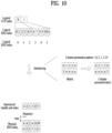
- the REGs may be dispersed in bundle units as much as possible at regular intervals in the bandwidth of the CORESET as shown in FIG. 9 or may be randomly dispersed in bundle units at irregular intervals. However, when bundling is not performed, the REGs may be dispersed in REG units.
- a block interleaver may be used in order to randomly disperse REGs in bundle units. For example, if the maximum number of REG bundles which may be included in the CORESET configured for the UE is m, the logical indices of REG bundles may be sequentially mapped to a matrix, the number of columns of which is fixed to k, row by row.
- the number 1 of rows of the matrix is a minimum integer satisfying m ⁇ l ⁇ k.
- an l ⁇ k matrix may be configured by filling the end of a last row with 1 ⁇ k-m null values. Thereafter, permutation is applied column by column using a predefined column permutation pattern and then elements are sequentially arranged column by column starting from the element of a first column, thereby interleaving the logical indices of the REG bundles.
- the logical indices of a plurality of REGs originally grouped in REG bundle units are sequentially mapped on the time axis, thereby randomly dispersing the REGs to the CORESET in bundle units in consideration of the time-axis bundle unit.
- the column size of the interleaved matrix and the column permutation pattern may be predefined in the system or may be signaled from the base station to the UE through higher layer signaling and/or physical layer signaling.
- FIG. 10 illustrates the detailed example of the above description.
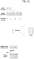
- the REG bundle units may be sufficiently randomly dispersed on the frequency axis.
- the logical indices of the REG bundles may be mapped to a matrix, the number of rows of which is fixed to k, column by column.
- a k ⁇ l matrix that is, a 5 ⁇ 2 matrix
- permutation is applied row by row using a predefined row permutation pattern and then elements are sequentially arranged row by row starting from the element of a first row, thereby interleaving the logical indices of the REG bundles.
- the logical indices of a plurality of REGs originally grouped in REG bundle units are sequentially mapped on the time axis, thereby randomly dispersing the REGs to the CORESET in bundle units in consideration of the time-axis bundle unit.
- the row size of the interleaved matrix and the row permutation pattern may be predefined in the system or may be signaled from the base station to the UE through higher layer signaling and/or physical layer signaling.
- the REG bundle units may be configured to be spread as evenly as possible in the bandwidth of the CORESET.
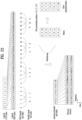
- the number of columns of the matrix in the block interleaver operation may be set to the number of units corresponding to one CCE (e.g., REG bundles corresponding to one CCE) and the column or row permutation process may not be performed.
- the column or row permutation process being not performed may mean that the column or row permutation pattern is ⁇ 0,1,2,3,4> based on the Embodiment 1-1.
- the number of columns of the matrix may be set to 3 to be equal to the number of REG bundles corresponding to one CCE.
- the logical indices of the REG bundles may be sequentially mapped to the matrix row by row and the elements may be sequentially arranged column by column starting from the element of the first column, thereby interleaving the logical indices of the REG bundles.
- the logical indices of a plurality of REGs originally grouped in REG bundle units are sequentially mapped on the time axis, thereby dispersing the REGs to the CORESET in bundle units at a regular interval in consideration of the time-axis bundle unit.
- the logical indices of the REG bundles may be sequentially mapped to the matrix column by column and the elements may be sequentially arranged row by row starting from the element of the first row, thereby interleaving the logical indices of the REG bundles.
- the logical indices of a plurality of REGs originally grouped in REG bundle units are sequentially mapped on the time axis, thereby dispersing the REGs to the CORESET in bundle units at a regular interval in consideration of the time-axis bundle unit.
- the column size of the interleaving of FIG. 12 or the row size of the interleaving matrix of FIG. 13 may be predefined in the system or may be signaled from the base station to the UE through higher layer signaling and/or physical layer signaling.
- REGs are bundled on the frequency axis, as shown in FIG. 14 , even when the CORESET includes a plurality of symbols, REGs configuring one CCE may be present in one symbol.
- Embodiment 1-1 is applicable to the method of randomly dispersing the REGs in bundle units without change.
- the indices of the REGs included in one bundle unit may be continuously mapped on the frequency axis, thereby randomly dispersing the REGs on the frequency axis while maintaining the bundle unit.
- Embodiment 1-2 is applicable to the method of dispersing the REGs in bundle units at a regular interval without change.
- the indices of the REGs included in one bundle unit may be continuously mapped on the frequency axis, thereby dispersing the REGs on the frequency at a regular interval while maintaining the bundle unit.
- the bandwidth of the CORESET may be configured to have a size which is not a multiple of the number of REGs configuring the REG bundle unit.
- the remaining region which cannot configure the REG bundle unit may be configured to be located at the front or back of the bandwidth region of the physical domain in which the CORESET is configured.
- the REG bundle unit index is further indexed in consideration of the remaining region which cannot configure the REG bundle unit and then interleaving is performed.
- Rate matching may be performed with respect to the logical REG bundle unit index mapped to the physical resource located at the front or back of the bandwidth region in which the CORESET is configured.
- rate matching may be performed with respect to control information corresponding to logical REG bundle unit index #1.
- the remaining region which cannot configure the REG bundle unit may be configured to be located at the front or back of the bandwidth region of the physical domain in which the CORESET is configured, and the REG bundle unit indices excluding the corresponding region are indexed to perform interleaving. That is, even when mapping is performed in the physical domain through interleaving, the corresponding region may not be used.
- the remaining region which cannot configure the REG bundle unit may be interleaved using the above-described method and may be used to reduce inter-cell interference instead of being used to map the control information.
- a value v shift may be set using cell-specific information such as a cell ID and the bandwidths of the CORESETs of different cells are differently set.
- the position and/or size of the bandwidth of the CORESET may be differently set for each cell in order to reduce inter-cell interference.
- the REGs may be bundled on the frequency axis while being bundled on the time axis. Therefore, frequency-axis bundling may be performed between REG bundle units included in different CCEs.
- the REGs may be bundled on the time axis between the REG bundle units included in different CCEs while being bundled on the frequency axis.
- a CCE bundle unit in which bundling between CCEs is performed may be set.
- the size of the CCE bundling unit and/or whether CCE bundling is performed on the time axis or the frequency axis may be predefined in the system, may be signaled from the base station to the UE through higher layer signaling and/or physical layer signaling, or may be set according to the CORESET configuration (e.g., CORESET duration).
- whether CCE bundling is performed on the time axis or the frequency axis may be determined according to the REG bundling configuration. That is, if REG bundling is performed on the time axis, CCE bundling may be performed on the frequency axis. In contrast, if REG bundling is performed on the frequency axis, CCE bundling may be performed on the time axis
- FIG. 21 shows an embodiment in which the CCE bundling unit is 2 on the frequency axis in a state in which REGs configure an REG bundle unit on the time axis by the length of the CORESET duration.
- the principle of the method of randomly performing interleaving in bundle chunk units may be equal to that of the method of performing interleaving in REG bundle units of Embodiment 1-1 and Embodiment 1-2.
- REG bundle units belonging to different CCEs to be bundled may be grouped to configure a new bundling unit. For example, if the size of each of the REG bundle unit and the CCE bundle unit is 2, the indices of the logical REGs configuring logical CCE index 0 may be 0, 1, 2, 3, 4 and 5 and the indices of the logical REGs configuring logical CCE index 1 may be 6, 7, 8, 9, 10 and 11.
- CCE 0 may be configured in REG bundle units of (0, 1), (2, 3) and (4, 5) and CCE1 may be configured in REG bundle units of (6, 7), (8, 9) and (10, 11).
- the REG bundle units belonging to the respective CCEs may form a pair such that ⁇ (0, 1), (6, 7) ⁇ , ⁇ (2, 3), (8, 9) ⁇ and ⁇ (4, 5), (10, 11) ⁇ configure respective new bundle chunks.
- an interleaver is applied based on the indexes and bundling is applied to the CCEs and the REGs, the CCEs and the REGs may be dispersed on the frequency axis in bundle units.
- the REG index belonging to the REG bundle index in the bundle chunk may be mapped on the time axis in the corresponding region and the REG bundles may be mapped on the frequency axis.
- the REG index belonging to the REG bundle index in the bundle chunk may be mapped on the frequency axis in the corresponding region and the REG bundles may be mapped on the time axis.
- the size of the columns or rows of the interleaved matrix and the column or row permutation pattern may be predefined in the system or may be signaled from the base station to the UE through higher layer signaling and/or physical layer signaling.
- FIGs. 24 and 25 An embodiment of performing interleaving between bundle chunks at a regular interval will be described with reference to FIGs. 24 and 25 .
- the size of the columns or rows of the interleaver matrix is set to the number of bundle chunk unit indices corresponding to the CCE bundling unit and column or row permutation is not applied, as shown in FIGs. 24 and 25 , interleaving between bundle chunks may be performed at a regular interval.
- interleaving may be performed such that the bundle chunks are further dispersed on the physical resources in CCE bundling size units.
- the indices may be indexed in CCE bundle units for the logical CCE indexes and interleaving may be applied to the CCE bundle units. Thereafter, after interleaving is performed based on the CCE bundle unit, when the logical indices of the CCEs belonging to the CCE bundle unit are listed, it is possible to configure interleaved logical CCE indices.
- the interleaved logical CCE indices are associated with the logical CCE indices described in Embodiments 1 to 2, the same result as the embodiments of FIGs. 26 and 27 can be obtained.
- the number of columns or rows of the matrix for interleaving the CCE bundle unit indices may be set to the number of CCE bundle unit indices corresponding to the CCE aggregation level.
- the REG indices corresponding to the interleaved logical CCE indices may be listed to configure interleaved logical REG indices and the REG bundle unit indices may be sequentially indexed.
- REG bundle units belonging to different CCEs to be bundled may be grouped and indexed with bundle chunk unit indices and interleaving may be performed with respect to the bundle chunk unit indices.
- the number of rows or columns of the matrix for interleaving the bundle chunk unit indices may be set to the number of bundle chunk unit indices corresponding to the size of the CCE bundle unit.
- the interleaved bundle chunk indices are mapped to the physical resources, if bundling between REGs is performed on the time axis and bundling between CCEs is performed on the frequency axis, the REG indices belonging to each REG bundle index in the bundle chunk may be mapped on the time axis in the corresponding region and the REG bundles may be mapped on the frequency axis.
- the REG indices belonging to each REG bundle index in the bundle chunk may be mapped on the frequency axis in the corresponding region and the REG bundles may be mapped on the time axis.
- the RBs configuring the CORESET may be continuously or separately configured in the frequency region and a combinational index defined in a legacy LTE system may be configured through higher layer signaling.
- Equation 1 the combinational index shown in Equation 1 may be used.
- k i i 0 N RB X p ⁇ 1 , ( 1 ⁇ k i ⁇ N RB DL , k i ⁇ k i+ 1 ) denotes a PRB index
- N RB X p denotes the number of RBs of the CORESET p
- N RB DL denotes the downlink bandwidth of the system.
- N RB X p and N RB DL of Equation 1 may be replaced by N RB / bundling size X p and N RB / bundling DL size).
- the combinational index derived using the above-described method may correspond to RB arrangement of the CORESET continuously or separately configured in bundle units.
- Intra-CCE or inter-CCE REG bundling may be performed as follows.
- inter-CCE REG bundling will be described.
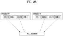
- REG bundling may be configured for each CORESET. If one candidate PDCCH is composed of CCEs belonging to several CORESETs, a set of inter-CCE bundles may be changed.
- inter-CCE bundling for CORESET 1 is performed through 1 and 3 and inter-CCE bundling for CORESET2 is performed through 2 and 3 or the corresponding CCE indexing is performed for each CORESET.
- the overlaid CCEs may be indexed again and bundling may be performed for each CORESET.
- intra-CCE REG bundling if one CCE is composed of REGs belonging to several CORESETs, the following method is applicable to intra-CCE REG bundling.
- the REG bundling size is 6, it may be assumed that one CCE is not mapped to several CORESETs.
- the REG bundling size may be 6/k. k may be the number of CORESETs, to which one CCE is mapped. REGs having the same index among the bundled REGs may be grouped to configure one CCE. If the time-domain REG bundling size is used, since 6/k may not be satisfied, the time-domain REG bundling may not be assumed if the corresponding method is used.
- a communication apparatus 2900 includes a processor 2910, a memory 2920, an RF module 2930, a display module 2940, and a User Interface (UI) module 2950.
- a processor 2910 includes a processor 2910, a memory 2920, an RF module 2930, a display module 2940, and a User Interface (UI) module 2950.
- UI User Interface
- the communication device 2900 is shown as having the configuration illustrated in FIG. 29 , for the convenience of description. Some modules may be added to or omitted from the communication apparatus 2900. In addition, a module of the communication apparatus 2900 may be divided into more modules.
- the processor 2910 is configured to perform operations according to the embodiments of the present disclosure described before with reference to the drawings. Specifically, for detailed operations of the processor 2910, the descriptions of FIGS. 1 to 28 may be referred to.
- the memory 2920 is connected to the processor 2910 and stores an Operating System (OS), applications, program codes, data, etc.
- the RF module 2930 which is connected to the processor 2910, upconverts a baseband signal to an RF signal or downconverts an RF signal to a baseband signal. For this purpose, the RF module 2930 performs digital-to-analog conversion, amplification, filtering, and frequency upconversion or performs these processes reversely.
- the display module 2940 is connected to the processor 2910 and displays various types of information.
- the display module 2940 may be configured as, not limited to, a known component such as a Liquid Crystal Display (LCD), a Light Emitting Diode (LED) display, and an Organic Light Emitting Diode (OLED) display.
- the UI module 2950 is connected to the processor 2910 and may be configured with a combination of known user interfaces such as a keypad, a touch screen, etc.
- a specific operation described as performed by a BS may be performed by an upper node of the BS. Namely, it is apparent that, in a network comprised of a plurality of network nodes including a BS, various operations performed for communication with a UE may be performed by the BS, or network nodes other than the BS.
- the term 'BS' may be replaced with the term 'fixed station', 'Node B', 'evolved Node B (eNode B or eNB)', 'Access Point (AP)', etc.
- the embodiments of the present invention may be achieved by various means, for example, hardware, firmware, software, or a combination thereof.
- the methods according to exemplary embodiments of the present invention may be achieved by one or more Application Specific Integrated Circuits (ASICs), Digital Signal Processors (DSPs), Digital Signal Processing Devices (DSPDs), Programmable Logic Devices (PLDs), Field Programmable Gate Arrays (FPGAs), processors, controllers, microcontrollers, microprocessors, etc.
- ASICs Application Specific Integrated Circuits
- DSPs Digital Signal Processors
- DSPDs Digital Signal Processing Devices
- PLDs Programmable Logic Devices
- FPGAs Field Programmable Gate Arrays
- processors controllers, microcontrollers, microprocessors, etc.
- an embodiment of the present invention may be implemented in the form of a module, a procedure, a function, etc.
- Software code may be stored in a memory unit and executed by a processor.
- the memory unit is located at the interior or exterior of the processor and may transmit and receive data to and from the processor via various known means.
- the present invention is applicable to various wireless communication systems in addition to the fifth-generation NewRAT system.
Landscapes
- Engineering & Computer Science (AREA)
- Signal Processing (AREA)
- Computer Networks & Wireless Communication (AREA)
- Mobile Radio Communication Systems (AREA)
Claims (7)
- Verfahren zum Empfangen eines Downlink-Steuerkanals, der mindestens ein Steuerkanalelement, CCE, umfasst, jeweils bestehend aus 6 Ressourcenelementgruppen, REGs, an einer Benutzerausrüstung, UE (2900), in einem drahtlosen Kommunikationssystem, wobei das Verfahren von der UE (2900) durchgeführt wird und Folgendes umfasst:Empfangen, von einer Basisstation, BS, über eine höhere Ebene, von ersten Informationen über eine REG-Bündelgröße zum Bündeln einer Vielzahl von REGs zu einem oder mehreren REG-Bündeln und zweiten Informationen über eine Größe einer Matrix zum Einfädeln der einen oder mehreren REG-Bündel;Empfangen, den Downlink-Steuerkanal über einen Steuerressourcensatz, CORESET, wobei die einen oder mehrere REG-Bündel basierend auf der Matrix innerhalb des CORESETs verschachtelt sind, wobei die Matrix basierend auf den ersten Informationen über die REG-Bündelgröße und der zweiten Informationen über die Größe der Matrix bestimmt wird, wobei eine Dauer des CORESETs so eingerichtet ist, dass sie 2 oder 3 Symbole für orthogonale Frequenzdivision, OFDM, multiplexiert,wobei die ersten Informationen über die REG-Bündelgröße basierend auf der Dauer des CORESETs eingerichtet wird, undwobei, basierend auf einem Wert der zweiten Informationen, der gleich einer Anzahl von REG-Bündeln ist, die in jeder CCE enthalten sind, die REG-Bündel jeder CCE in regelmäßigen Abständen physischen Ressourcen zugeordnet werden.
- Verfahren nach Anspruch 1, wobei, basierend auf einer Anzahl von Zeilen der Matrix, die keine Ganzzahl ist, eine Ganzzahl mit einem Mindestwert unter Ganzzahlen, der größer als die ermittelte Anzahl der Zeilen der Matrix ist, als die Anzahl der Zeilen der Matrix, bestimmt wird.
- Benutzerausrüstung, UE (2900), zum Empfangen eines Downlink-Steuerkanals, umfassend mindestens ein Steuerkanalelement, CCE, jeweils bestehend aus 6 Ressourcenelementgruppen, REGs, in einem drahtlosen Kommunikationssystem, wobei die UE (2900) Folgendes umfasst:ein Funkfrequenz-, RF-, Modul (2930) zum Senden und Empfangen eines Funksignals zu und von einer Basisstation; undmindestens einen Prozessor (2910), der mit dem RF-Modul verbunden und zu Folgendem eingerichtet ist:Empfangen, von der Basisstation, BS, über eine höhere Schicht, erster Informationen über eine REG-Bündelgröße zum Bündeln einer Vielzahl von REGs in ein oder mehrere REG-Bündel und zweiter Informationen über eine Größe einer Matrix zum Verschachteln von REG-Bündeln,Empfangen des Downlink-Steuerkanals über einen Steuerressourcensatz, CORESET, wobei ein oder mehrere REG-Bündel innerhalb des CORESETs basierend auf der Matrix verschachtelt sind, wobei die Matrix basierend auf den ersten Informationen über die REG-Bündelgröße und den zweiten Informationen über die Größe der Matrix bestimmt wird,wobei eine Dauer des CORESETs so eingerichtet ist, dass sie 2 oder 3 Symbole für orthogonale Frequenzdivision, OFDM, multiplexiert,wobei die ersten Informationen über die REG-Bündelgröße basierend auf der Dauer des CORESETs eingerichtet wird, undwobei, basierend auf einem Wert der zweiten Informationen, der gleich einer Anzahl von REG-Bündeln ist, die in jeder CCE enthalten sind, die REG-Bündel jeder CCE in regelmäßigen Abständen physischen Ressourcen zugeordnet werden.
- UE (2900) nach Anspruch 3, wobei, basierend auf einer Anzahl von Zeilen der Matrix, die keine Ganzzahl ist, eine Ganzzahl mit einem Mindestwert unter Ganzzahlen, der größer als die bestimmte Anzahl der Zeilen der Matrix ist, als die Anzahl der Zeilen der Matrix, bestimmt wird.
- Verfahren zum Senden eines Downlink-Steuerkanals, der mindestens ein Steuerkanalelement, CCE, umfasst, das jeweils aus 6 Ressourcenelementgruppen, REGs, besteht, an einer Basisstation, BS, in einem drahtlosen Kommunikationssystem, wobei das von der BS durchgeführte Verfahren Folgendes umfasst:Übertragen von ersten Informationen über eine Ressourcenelementgruppen-, REG-, Bündelgröße zum Bündeln einer Vielzahl von REGs in ein oder mehrere REG-Bündel und von zweiten Informationen über eine Größe einer Matrix zum Verschachteln des einen oder der mehreren REG-Bündel über eine höhere Ebene an eine Benutzerausrüstung, UE (2900);Verschachteln der einen oder mehreren REG-Bündel innerhalb eines Steuerressourcensatzes, CORESETs, basierend auf der Matrix, wobei die Matrix basierend auf den ersten Informationen über die REG-Bündelgröße und den zweiten Informationen über die Größe der Matrix bestimmt wird; undSenden des Downlink-Steuerkanals über den CORESET an die UE (2900),wobei eine Dauer des CORESETs so eingerichtet ist, dass sie 2 oder 3 Symbole für orthogonale Frequenzdivision, OFDM, multiplexiert,wobei die ersten Informationen über die REG-Bündelgröße basierend auf der Dauer des CORESETs eingerichtet sind,wobei, basierend auf einem Wert der zweiten Informationen, der gleich einer Anzahl von REG-Bündeln ist, die in jeder CCE enthalten sind, die REG-Bündel jeder CCE in regelmäßigen Abständen physischen Ressourcen zugeordnet werden.
- Basisstation, BS, eingerichtet zum Senden eines Downlink-Steuerkanals, der mindestens ein Steuerkanalelement, CCE, umfasst, jeweils bestehend aus 6 Ressourcenelementgruppen, REGs, in einem drahtlosen Kommunikationssystem, wobei die BS Folgendes umfasst:mindestens einen Speicher, der zum Speichern von Anweisungen eingerichtet ist,mindestens einen Prozessor, der so eingerichtet ist, dass er Vorgänge auf der Grundlage der Anweisungen durchführt, wobei die Vorgänge Folgendes umfassen:Übertragen von ersten Informationen über eine Ressourcenelementgruppen-, REG-, Bündelgröße zum Bündeln einer Vielzahl von REGs in ein oder mehrere REG-Bündel und von zweiten Informationen über eine Größe einer Matrix zum Verschachteln des einen oder der mehreren REG-Bündel über eine höhere Ebene an eine Benutzerausrüstung, UE (2900);Verschachteln der einen oder mehreren REG-Bündel innerhalb eines Steuerressourcensatzes, CORESETs, basierend auf der Matrix, wobei die Matrix basierend auf den ersten Informationen über die REG-Bündelgröße und den zweiten Informationen über die Größe der Matrix bestimmt wird; undSenden des Downlink-Steuerkanals über den CORESET an die UE (2900),wobei eine Dauer des CORESETs so eingerichtet ist, dass sie 2 oder 3 Symbole für orthogonale Frequenzdivision, OFDM, multiplexiert,wobei die ersten Informationen über die REG-Bündelgröße basierend auf der Dauer des CORESETs eingerichtet sind,wobei, basierend auf einem Wert der zweiten Informationen, der gleich einer Anzahl von REG-Bündeln ist, die in jeder CCE enthalten sind, die REG-Bündel jeder CCE in regelmäßigen Abständen physischen Ressourcen zugeordnet werden.
- Computerlesbares Medium, das Anweisungen speichert, die, wenn sie von einem Prozessor ausgeführt werden, den Prozessor veranlassen, das Verfahren nach einem der Ansprüche 1, 2 oder 5 auszuführen.
Priority Applications (1)
| Application Number | Priority Date | Filing Date | Title |
|---|---|---|---|
| EP23214501.1A EP4311142A3 (de) | 2017-04-28 | 2018-04-27 | Verfahren zum empfangen eines downlink-steuerkanals und vorrichtung dafür |
Applications Claiming Priority (4)
| Application Number | Priority Date | Filing Date | Title |
|---|---|---|---|
| US201762491927P | 2017-04-28 | 2017-04-28 | |
| US201762505852P | 2017-05-13 | 2017-05-13 | |
| US201762521323P | 2017-06-16 | 2017-06-16 | |
| PCT/KR2018/004921 WO2018199684A1 (ko) | 2017-04-28 | 2018-04-27 | 하향링크 제어 채널을 수신하는 방법 및 이를 위한 장치 |
Related Child Applications (2)
| Application Number | Title | Priority Date | Filing Date |
|---|---|---|---|
| EP23214501.1A Division EP4311142A3 (de) | 2017-04-28 | 2018-04-27 | Verfahren zum empfangen eines downlink-steuerkanals und vorrichtung dafür |
| EP23214501.1A Division-Into EP4311142A3 (de) | 2017-04-28 | 2018-04-27 | Verfahren zum empfangen eines downlink-steuerkanals und vorrichtung dafür |
Publications (3)
| Publication Number | Publication Date |
|---|---|
| EP3480994A1 EP3480994A1 (de) | 2019-05-08 |
| EP3480994A4 EP3480994A4 (de) | 2020-02-26 |
| EP3480994B1 true EP3480994B1 (de) | 2025-06-04 |
Family
ID=63918521
Family Applications (2)
| Application Number | Title | Priority Date | Filing Date |
|---|---|---|---|
| EP18790941.1A Active EP3480994B1 (de) | 2017-04-28 | 2018-04-27 | Verfahren zum empfangen eines downlink-steuerkanals und vorrichtung dafür |
| EP23214501.1A Pending EP4311142A3 (de) | 2017-04-28 | 2018-04-27 | Verfahren zum empfangen eines downlink-steuerkanals und vorrichtung dafür |
Family Applications After (1)
| Application Number | Title | Priority Date | Filing Date |
|---|---|---|---|
| EP23214501.1A Pending EP4311142A3 (de) | 2017-04-28 | 2018-04-27 | Verfahren zum empfangen eines downlink-steuerkanals und vorrichtung dafür |
Country Status (12)
| Country | Link |
|---|---|
| US (6) | US10455573B2 (de) |
| EP (2) | EP3480994B1 (de) |
| JP (1) | JP6750049B2 (de) |
| KR (2) | KR101921184B1 (de) |
| CN (2) | CN110383746B (de) |
| AU (1) | AU2018257256B2 (de) |
| BR (1) | BR112019001725B1 (de) |
| ES (1) | ES3033809T3 (de) |
| MX (1) | MX386563B (de) |
| RU (1) | RU2721680C1 (de) |
| SG (2) | SG10202107521TA (de) |
| WO (1) | WO2018199684A1 (de) |
Families Citing this family (16)
| Publication number | Priority date | Publication date | Assignee | Title |
|---|---|---|---|---|
| KR20250027856A (ko) * | 2017-02-03 | 2025-02-27 | 인터디지탈 패튼 홀딩스, 인크 | 물리적인 다운링크 제어 채널에서의 전달과 수신 |
| MX2019012992A (es) * | 2017-05-02 | 2019-12-18 | Guangdong Oppo Mobile Telecommunications Corp Ltd | Metodos y aparatos para agrupar y mapear recursos de control en sistemas de comunicacion inalambrica. |
| CN113783678B (zh) * | 2017-05-04 | 2023-03-10 | 华为技术有限公司 | 通信方法和通信装置 |
| CN108809505B (zh) * | 2017-05-05 | 2019-12-24 | 维沃移动通信有限公司 | 下行控制信息的传输方法、终端及网络侧设备 |
| EP4521692A3 (de) * | 2017-08-03 | 2025-05-07 | NEC Corporation | Verfahren und vorrichtungen zur steuerung von ressourcenzuordnung |
| CN115567974A (zh) * | 2017-08-11 | 2023-01-03 | 华为技术有限公司 | 一种信息的发送方法及设备 |
| US20190158205A1 (en) * | 2017-11-17 | 2019-05-23 | Sharp Laboratories Of America, Inc. | User equipments, base stations and methods |
| US11240796B2 (en) * | 2018-01-12 | 2022-02-01 | Telefonaktiebolaget Lm Ericsson (Publ) | Wireless communication block interleaving |
| CN110035533B (zh) * | 2018-01-12 | 2023-06-06 | 华为技术有限公司 | 一种资源映射方法及设备 |
| US12170626B2 (en) | 2019-06-25 | 2024-12-17 | Telefonaktiebolaget Lm Ericsson (Publ) | Systems and methods of joint HARQ feedback for PDSCH transmission over multiple TRPs |
| US12160385B2 (en) | 2019-09-03 | 2024-12-03 | Nokia Technologies Oy | Single carrier control channel |
| CN110784927A (zh) * | 2019-11-08 | 2020-02-11 | 展讯通信(上海)有限公司 | Pdcch监听方法及装置、存储介质、终端 |
| CN113677025B (zh) * | 2020-05-15 | 2024-05-14 | 华为技术有限公司 | 一种通信方法和通信装置 |
| US12401452B2 (en) * | 2020-06-16 | 2025-08-26 | Qualcomm Incorporated | PDCCH interleaving enhancement for monitoring aggregation |
| US12069701B2 (en) | 2021-04-21 | 2024-08-20 | Qualcomm Incorporated | Configuring a time domain control resource set for single carrier waveforms |
| CN117546562A (zh) * | 2022-04-08 | 2024-02-09 | 北京小米移动软件有限公司 | 频域资源配置方法及装置 |
Family Cites Families (37)
| Publication number | Priority date | Publication date | Assignee | Title |
|---|---|---|---|---|
| US8254245B2 (en) * | 2007-04-27 | 2012-08-28 | Lg Electronics Inc. | Method for transmitting downlink control channel in a mobile communications system and a method for mapping the control channel to physical resource using block interleaver in a mobile communications system |
| EP2335372B1 (de) * | 2008-10-08 | 2018-02-14 | Telefonaktiebolaget LM Ericsson (publ) | Verfahren und vorrichtung zur auswahl von steurkanalelementen in einem physischen downlinksteuerkanal |
| KR101629298B1 (ko) * | 2008-10-30 | 2016-06-10 | 엘지전자 주식회사 | 무선 통신 시스템에서 제어 신호를 전송하는 방법 및 이를 위한 장치 |
| US8625521B2 (en) | 2009-05-14 | 2014-01-07 | Lg Electronics Inc. | Apparatus and method for monitoring control channel in multi-carrier system |
| WO2011056016A2 (en) * | 2009-11-06 | 2011-05-12 | Lg Electronics Inc. | Method of resource block (rb) bundling |
| KR101053635B1 (ko) * | 2010-01-28 | 2011-08-03 | 엘지전자 주식회사 | 다중 안테나 무선 통신 시스템에서 기지국이 릴레이 노드로 제어 신호를 송신하는 방법 및 이를 위한 장치 |
| CA2797398C (en) | 2010-05-14 | 2017-01-24 | Lg Electronics Inc. | Method for allocating resources in a wireless communication system and a device for the same |
| US8780766B2 (en) * | 2010-08-16 | 2014-07-15 | Qualcomm Incorporated | Interleaving for relay physical downlink control channel (R-PDCCH) |
| KR102014793B1 (ko) * | 2011-08-19 | 2019-08-27 | 엘지전자 주식회사 | 무선 통신 시스템에서 기지국이 하향링크 제어 채널을 송신하는 방법 및 이를 위한 장치 |
| KR20130076456A (ko) * | 2011-12-28 | 2013-07-08 | 주식회사 팬택 | 무선 통신 시스템에 있어서 제어 정보의 송수신 방법 및 장치 |
| KR101939295B1 (ko) | 2012-02-11 | 2019-01-16 | 엘지전자 주식회사 | 다중 셀 기반 무선 통신 시스템에서 하향링크 데이터 채널 수신 방법 및 이를 위한 장치 |
| US9544110B2 (en) | 2012-02-11 | 2017-01-10 | Lg Electronics Inc. | Method for receiving downlink data channels in multicell-based wireless communication systems and apparatus for same |
| CN103391619B (zh) | 2012-05-09 | 2016-12-14 | 上海贝尔股份有限公司 | 在通信网络中进行ePDCCH资源元素映射的方法和装置 |
| WO2014019208A1 (zh) * | 2012-08-02 | 2014-02-06 | 华为技术有限公司 | 传输控制信息的方法、装置及系统 |
| KR102201750B1 (ko) * | 2012-08-11 | 2021-01-12 | 엘지전자 주식회사 | 무선 통신 시스템에서 하향링크 제어 채널을 수신하는 방법 및 이를 위한 장치 |
| US9143291B2 (en) * | 2012-12-27 | 2015-09-22 | Google Technology Holdings LLC | Method and apparatus for device-to-device communication |
| EP3000199B1 (de) | 2013-05-21 | 2019-09-25 | Telefonaktiebolaget LM Ericsson (publ) | Übertragungs- und empfangsverfahren sowie zugehörige kommunikationsvorrichtungen zur verwendung in einem ofdm-basierten kommunikationsnetz |
| WO2017193396A1 (zh) * | 2016-05-13 | 2017-11-16 | 华为技术有限公司 | 信息处理方法、终端及基站 |
| US10305633B2 (en) * | 2016-09-19 | 2019-05-28 | Qualcomm Incorporated | Per-symbol K-bit interleaver |
| KR20250027856A (ko) * | 2017-02-03 | 2025-02-27 | 인터디지탈 패튼 홀딩스, 인크 | 물리적인 다운링크 제어 채널에서의 전달과 수신 |
| US10432441B2 (en) | 2017-02-06 | 2019-10-01 | Samsung Electronics Co., Ltd. | Transmission structures and formats for DL control channels |
| WO2018151871A2 (en) * | 2017-02-17 | 2018-08-23 | Intel IP Corporation | Control resource block set search space design |
| CA3057008A1 (en) * | 2017-03-21 | 2018-09-27 | Ntt Docomo, Inc. | User terminal and radio communication method |
| US10757581B2 (en) * | 2017-03-22 | 2020-08-25 | Mediatek Inc. | Physical downlink control channel design for NR systems |
| US10925048B2 (en) * | 2017-03-30 | 2021-02-16 | Qualcomm Incorporated | Control resource set for single-carrier waveform |
| EP3607682A1 (de) * | 2017-04-05 | 2020-02-12 | Intel IP Corporation | Reg-bündelungsgrösse und dm-rs-muster für physikalischen downlink-steuerkanal |
| ES2940475T3 (es) * | 2017-04-26 | 2023-05-08 | Sharp Kk | Dispositivo terminal, dispositivo de estación base y método de comunicación |
| CN113783678B (zh) | 2017-05-04 | 2023-03-10 | 华为技术有限公司 | 通信方法和通信装置 |
| JP7248594B2 (ja) | 2018-01-05 | 2023-03-29 | 株式会社Nttドコモ | 端末、無線通信方法、基地局及びシステム |
| US11272566B2 (en) | 2018-01-11 | 2022-03-08 | Sharp Kabushiki Kaisha | User equipments, base stations and methods |
| US10826758B2 (en) | 2018-02-14 | 2020-11-03 | Asustek Computer Inc. | Method and apparatus for control resource monitoring considering beam failure recovery in a wireless communication system |
| US10973016B2 (en) | 2018-03-23 | 2021-04-06 | Samsung Electronics Co., Ltd | Method and apparatus for transmitting downlink control information in wireless communication system |
| US11102643B2 (en) | 2018-03-30 | 2021-08-24 | Asustek Computer Inc. | Method and apparatus for determining size of preemption indication in a wireless communication system |
| KR102206806B1 (ko) | 2018-05-04 | 2021-01-25 | 아서스테크 컴퓨터 인코포레이션 | 무선 통신 시스템에서 액티브 다운링크 대역폭 부분 변경을 고려한 다운링크 제어 정보 컨텐트 프로세싱을 위한 방법 및 장치 |
| KR20200031446A (ko) | 2018-09-14 | 2020-03-24 | 삼성전자주식회사 | 무선 통신 시스템에서 pdcch 모니터링 방법 및 장치 |
| WO2020197215A1 (en) | 2019-03-22 | 2020-10-01 | Samsung Electronics Co., Ltd. | Method and apparatus for control channel reception in wireless communication systems |
| CN114270719B (zh) | 2019-08-23 | 2025-04-25 | 三星电子株式会社 | 用于在无线协作通信系统中发送或接收多条数据的方法和设备 |
-
2018
- 2018-04-27 EP EP18790941.1A patent/EP3480994B1/de active Active
- 2018-04-27 KR KR1020180048989A patent/KR101921184B1/ko active Active
- 2018-04-27 JP JP2018568953A patent/JP6750049B2/ja active Active
- 2018-04-27 SG SG10202107521TA patent/SG10202107521TA/en unknown
- 2018-04-27 MX MX2019001236A patent/MX386563B/es unknown
- 2018-04-27 RU RU2019110421A patent/RU2721680C1/ru active
- 2018-04-27 CN CN201880016807.0A patent/CN110383746B/zh active Active
- 2018-04-27 US US16/065,561 patent/US10455573B2/en active Active
- 2018-04-27 AU AU2018257256A patent/AU2018257256B2/en active Active
- 2018-04-27 BR BR112019001725-9A patent/BR112019001725B1/pt active IP Right Grant
- 2018-04-27 EP EP23214501.1A patent/EP4311142A3/de active Pending
- 2018-04-27 SG SG11201811699YA patent/SG11201811699YA/en unknown
- 2018-04-27 ES ES18790941T patent/ES3033809T3/es active Active
- 2018-04-27 CN CN202111061178.3A patent/CN113890705B/zh active Active
- 2018-04-27 WO PCT/KR2018/004921 patent/WO2018199684A1/ko not_active Ceased
- 2018-11-13 KR KR1020180139017A patent/KR102129801B1/ko active Active
-
2019
- 2019-08-01 US US16/529,117 patent/US10912073B2/en active Active
-
2021
- 2021-01-22 US US17/156,059 patent/US11564219B2/en active Active
- 2021-03-19 US US17/206,898 patent/US11246128B2/en active Active
-
2023
- 2023-01-05 US US18/093,563 patent/US11910403B2/en active Active
-
2024
- 2024-01-22 US US18/419,009 patent/US20240163888A1/en active Pending
Also Published As
Similar Documents
| Publication | Publication Date | Title |
|---|---|---|
| US11910403B2 (en) | Method and apparatus for transmitting and receiving downlink control channel | |
| US10568086B2 (en) | Method for transmitting and receiving physical downlink shared channel and demodulation reference signal and apparatus therefor | |
| EP3579466B1 (de) | Verfahren zum senden eines harq-ack-signals in einem drahtloskommunikationssystem und vorrichtung dafür | |
| EP2747321B1 (de) | Verfahren für eine basisstation zum übertragen von downlink-steuerkanälen in einem drahtlosen kommunikationssystem und vorrichtung dafür | |
| EP3641195B1 (de) | Verfahren zum empfangen eines downlink-steuerkanals und vorrichtung dafür | |
| US9614643B2 (en) | Method for transmitting a downlink control channel by a base station in a wireless communication system, and apparatus therefor |
Legal Events
| Date | Code | Title | Description |
|---|---|---|---|
| STAA | Information on the status of an ep patent application or granted ep patent |
Free format text: STATUS: THE INTERNATIONAL PUBLICATION HAS BEEN MADE |
|
| PUAI | Public reference made under article 153(3) epc to a published international application that has entered the european phase |
Free format text: ORIGINAL CODE: 0009012 |
|
| STAA | Information on the status of an ep patent application or granted ep patent |
Free format text: STATUS: REQUEST FOR EXAMINATION WAS MADE |
|
| 17P | Request for examination filed |
Effective date: 20190114 |
|
| AK | Designated contracting states |
Kind code of ref document: A1 Designated state(s): AL AT BE BG CH CY CZ DE DK EE ES FI FR GB GR HR HU IE IS IT LI LT LU LV MC MK MT NL NO PL PT RO RS SE SI SK SM TR |
|
| AX | Request for extension of the european patent |
Extension state: BA ME |
|
| A4 | Supplementary search report drawn up and despatched |
Effective date: 20200124 |
|
| RIC1 | Information provided on ipc code assigned before grant |
Ipc: H04W 72/04 20090101ALI20200120BHEP Ipc: H04L 5/00 20060101AFI20200120BHEP Ipc: H04L 1/00 20060101ALI20200120BHEP |
|
| DAV | Request for validation of the european patent (deleted) | ||
| DAX | Request for extension of the european patent (deleted) | ||
| STAA | Information on the status of an ep patent application or granted ep patent |
Free format text: STATUS: EXAMINATION IS IN PROGRESS |
|
| 17Q | First examination report despatched |
Effective date: 20210525 |
|
| GRAP | Despatch of communication of intention to grant a patent |
Free format text: ORIGINAL CODE: EPIDOSNIGR1 |
|
| STAA | Information on the status of an ep patent application or granted ep patent |
Free format text: STATUS: GRANT OF PATENT IS INTENDED |
|
| GRAJ | Information related to disapproval of communication of intention to grant by the applicant or resumption of examination proceedings by the epo deleted |
Free format text: ORIGINAL CODE: EPIDOSDIGR1 |
|
| STAA | Information on the status of an ep patent application or granted ep patent |
Free format text: STATUS: EXAMINATION IS IN PROGRESS |
|
| RIC1 | Information provided on ipc code assigned before grant |
Ipc: H04W 72/23 20230101ALI20240222BHEP Ipc: H04L 1/00 20060101ALI20240222BHEP Ipc: H04L 5/00 20060101AFI20240222BHEP |
|
| INTG | Intention to grant announced |
Effective date: 20240312 |
|
| INTC | Intention to grant announced (deleted) | ||
| GRAP | Despatch of communication of intention to grant a patent |
Free format text: ORIGINAL CODE: EPIDOSNIGR1 |
|
| STAA | Information on the status of an ep patent application or granted ep patent |
Free format text: STATUS: GRANT OF PATENT IS INTENDED |
|
| INTG | Intention to grant announced |
Effective date: 20241223 |
|
| GRAS | Grant fee paid |
Free format text: ORIGINAL CODE: EPIDOSNIGR3 |
|
| GRAA | (expected) grant |
Free format text: ORIGINAL CODE: 0009210 |
|
| STAA | Information on the status of an ep patent application or granted ep patent |
Free format text: STATUS: THE PATENT HAS BEEN GRANTED |
|
| AK | Designated contracting states |
Kind code of ref document: B1 Designated state(s): AL AT BE BG CH CY CZ DE DK EE ES FI FR GB GR HR HU IE IS IT LI LT LU LV MC MK MT NL NO PL PT RO RS SE SI SK SM TR |
|
| REG | Reference to a national code |
Ref country code: GB Ref legal event code: FG4D |
|
| REG | Reference to a national code |
Ref country code: CH Ref legal event code: EP |
|
| REG | Reference to a national code |
Ref country code: DE Ref legal event code: R096 Ref document number: 602018082421 Country of ref document: DE |
|
| REG | Reference to a national code |
Ref country code: IE Ref legal event code: FG4D |
|
| REG | Reference to a national code |
Ref country code: NL Ref legal event code: FP |
|
| REG | Reference to a national code |
Ref country code: ES Ref legal event code: FG2A Ref document number: 3033809 Country of ref document: ES Kind code of ref document: T3 Effective date: 20250808 |
|
| PG25 | Lapsed in a contracting state [announced via postgrant information from national office to epo] |
Ref country code: FI Free format text: LAPSE BECAUSE OF FAILURE TO SUBMIT A TRANSLATION OF THE DESCRIPTION OR TO PAY THE FEE WITHIN THE PRESCRIBED TIME-LIMIT Effective date: 20250604 |
|
| REG | Reference to a national code |
Ref country code: LT Ref legal event code: MG9D |
|
| PG25 | Lapsed in a contracting state [announced via postgrant information from national office to epo] |
Ref country code: NO Free format text: LAPSE BECAUSE OF FAILURE TO SUBMIT A TRANSLATION OF THE DESCRIPTION OR TO PAY THE FEE WITHIN THE PRESCRIBED TIME-LIMIT Effective date: 20250904 Ref country code: GR Free format text: LAPSE BECAUSE OF FAILURE TO SUBMIT A TRANSLATION OF THE DESCRIPTION OR TO PAY THE FEE WITHIN THE PRESCRIBED TIME-LIMIT Effective date: 20250905 |
|
| PG25 | Lapsed in a contracting state [announced via postgrant information from national office to epo] |
Ref country code: PL Free format text: LAPSE BECAUSE OF FAILURE TO SUBMIT A TRANSLATION OF THE DESCRIPTION OR TO PAY THE FEE WITHIN THE PRESCRIBED TIME-LIMIT Effective date: 20250604 |
|
| PG25 | Lapsed in a contracting state [announced via postgrant information from national office to epo] |
Ref country code: BG Free format text: LAPSE BECAUSE OF FAILURE TO SUBMIT A TRANSLATION OF THE DESCRIPTION OR TO PAY THE FEE WITHIN THE PRESCRIBED TIME-LIMIT Effective date: 20250604 |
|
| PG25 | Lapsed in a contracting state [announced via postgrant information from national office to epo] |
Ref country code: HR Free format text: LAPSE BECAUSE OF FAILURE TO SUBMIT A TRANSLATION OF THE DESCRIPTION OR TO PAY THE FEE WITHIN THE PRESCRIBED TIME-LIMIT Effective date: 20250604 |
|
| PG25 | Lapsed in a contracting state [announced via postgrant information from national office to epo] |
Ref country code: RS Free format text: LAPSE BECAUSE OF FAILURE TO SUBMIT A TRANSLATION OF THE DESCRIPTION OR TO PAY THE FEE WITHIN THE PRESCRIBED TIME-LIMIT Effective date: 20250904 |
|
| PG25 | Lapsed in a contracting state [announced via postgrant information from national office to epo] |
Ref country code: LV Free format text: LAPSE BECAUSE OF FAILURE TO SUBMIT A TRANSLATION OF THE DESCRIPTION OR TO PAY THE FEE WITHIN THE PRESCRIBED TIME-LIMIT Effective date: 20250604 |
|
| PG25 | Lapsed in a contracting state [announced via postgrant information from national office to epo] |
Ref country code: PT Free format text: LAPSE BECAUSE OF FAILURE TO SUBMIT A TRANSLATION OF THE DESCRIPTION OR TO PAY THE FEE WITHIN THE PRESCRIBED TIME-LIMIT Effective date: 20251006 |
|
| REG | Reference to a national code |
Ref country code: AT Ref legal event code: MK05 Ref document number: 1801416 Country of ref document: AT Kind code of ref document: T Effective date: 20250604 |
|
| PG25 | Lapsed in a contracting state [announced via postgrant information from national office to epo] |
Ref country code: IS Free format text: LAPSE BECAUSE OF FAILURE TO SUBMIT A TRANSLATION OF THE DESCRIPTION OR TO PAY THE FEE WITHIN THE PRESCRIBED TIME-LIMIT Effective date: 20251004 |
|
| PG25 | Lapsed in a contracting state [announced via postgrant information from national office to epo] |
Ref country code: AT Free format text: LAPSE BECAUSE OF FAILURE TO SUBMIT A TRANSLATION OF THE DESCRIPTION OR TO PAY THE FEE WITHIN THE PRESCRIBED TIME-LIMIT Effective date: 20250604 Ref country code: SM Free format text: LAPSE BECAUSE OF FAILURE TO SUBMIT A TRANSLATION OF THE DESCRIPTION OR TO PAY THE FEE WITHIN THE PRESCRIBED TIME-LIMIT Effective date: 20250604 |
|
| PG25 | Lapsed in a contracting state [announced via postgrant information from national office to epo] |
Ref country code: CZ Free format text: LAPSE BECAUSE OF FAILURE TO SUBMIT A TRANSLATION OF THE DESCRIPTION OR TO PAY THE FEE WITHIN THE PRESCRIBED TIME-LIMIT Effective date: 20250604 |
|
| PG25 | Lapsed in a contracting state [announced via postgrant information from national office to epo] |
Ref country code: EE Free format text: LAPSE BECAUSE OF FAILURE TO SUBMIT A TRANSLATION OF THE DESCRIPTION OR TO PAY THE FEE WITHIN THE PRESCRIBED TIME-LIMIT Effective date: 20250604 |
|
| PG25 | Lapsed in a contracting state [announced via postgrant information from national office to epo] |
Ref country code: SK Free format text: LAPSE BECAUSE OF FAILURE TO SUBMIT A TRANSLATION OF THE DESCRIPTION OR TO PAY THE FEE WITHIN THE PRESCRIBED TIME-LIMIT Effective date: 20250604 Ref country code: RO Free format text: LAPSE BECAUSE OF FAILURE TO SUBMIT A TRANSLATION OF THE DESCRIPTION OR TO PAY THE FEE WITHIN THE PRESCRIBED TIME-LIMIT Effective date: 20250604 |