EP3480895B1 - Device connection unit for an electrical device and electrical device - Google Patents
Device connection unit for an electrical device and electrical device Download PDFInfo
- Publication number
- EP3480895B1 EP3480895B1 EP18204615.1A EP18204615A EP3480895B1 EP 3480895 B1 EP3480895 B1 EP 3480895B1 EP 18204615 A EP18204615 A EP 18204615A EP 3480895 B1 EP3480895 B1 EP 3480895B1
- Authority
- EP
- European Patent Office
- Prior art keywords
- conductor
- supply
- contacting
- electrical
- connection unit
- Prior art date
- Legal status (The legal status is an assumption and is not a legal conclusion. Google has not performed a legal analysis and makes no representation as to the accuracy of the status listed.)
- Active
Links
- 239000004020 conductor Substances 0.000 claims description 163
- 238000003780 insertion Methods 0.000 claims description 24
- 230000037431 insertion Effects 0.000 claims description 24
- 230000001681 protective effect Effects 0.000 claims description 14
- RYGMFSIKBFXOCR-UHFFFAOYSA-N Copper Chemical compound [Cu] RYGMFSIKBFXOCR-UHFFFAOYSA-N 0.000 description 6
- 239000000463 material Substances 0.000 description 6
- 229910052802 copper Inorganic materials 0.000 description 5
- 239000010949 copper Substances 0.000 description 5
- 238000003825 pressing Methods 0.000 description 5
- BQCADISMDOOEFD-UHFFFAOYSA-N Silver Chemical compound [Ag] BQCADISMDOOEFD-UHFFFAOYSA-N 0.000 description 4
- 230000005540 biological transmission Effects 0.000 description 4
- 229910052709 silver Inorganic materials 0.000 description 4
- 239000004332 silver Substances 0.000 description 4
- 210000003462 vein Anatomy 0.000 description 3
- 229910000639 Spring steel Inorganic materials 0.000 description 2
- 229910052782 aluminium Inorganic materials 0.000 description 2
- XAGFODPZIPBFFR-UHFFFAOYSA-N aluminium Chemical compound [Al] XAGFODPZIPBFFR-UHFFFAOYSA-N 0.000 description 2
- 238000010616 electrical installation Methods 0.000 description 2
- 238000005516 engineering process Methods 0.000 description 2
- 230000005923 long-lasting effect Effects 0.000 description 2
- 229910052751 metal Inorganic materials 0.000 description 2
- 239000002184 metal Substances 0.000 description 2
- 239000002994 raw material Substances 0.000 description 2
- 239000004411 aluminium Substances 0.000 description 1
- 238000005452 bending Methods 0.000 description 1
- 230000003247 decreasing effect Effects 0.000 description 1
- 230000000694 effects Effects 0.000 description 1
- 230000005489 elastic deformation Effects 0.000 description 1
- 238000004870 electrical engineering Methods 0.000 description 1
- 238000009434 installation Methods 0.000 description 1
- 238000009413 insulation Methods 0.000 description 1
- 239000002655 kraft paper Substances 0.000 description 1
- 230000007774 longterm Effects 0.000 description 1
- 238000004519 manufacturing process Methods 0.000 description 1
- 230000007935 neutral effect Effects 0.000 description 1
- 238000010008 shearing Methods 0.000 description 1
- 238000005476 soldering Methods 0.000 description 1
- 239000007787 solid Substances 0.000 description 1
- 210000002023 somite Anatomy 0.000 description 1
- 238000005406 washing Methods 0.000 description 1
- 238000004804 winding Methods 0.000 description 1
Images
Classifications
-
- H—ELECTRICITY
- H01—ELECTRIC ELEMENTS
- H01R—ELECTRICALLY-CONDUCTIVE CONNECTIONS; STRUCTURAL ASSOCIATIONS OF A PLURALITY OF MUTUALLY-INSULATED ELECTRICAL CONNECTING ELEMENTS; COUPLING DEVICES; CURRENT COLLECTORS
- H01R24/00—Two-part coupling devices, or either of their cooperating parts, characterised by their overall structure
- H01R24/28—Coupling parts carrying pins, blades or analogous contacts and secured only to wire or cable
- H01R24/30—Coupling parts carrying pins, blades or analogous contacts and secured only to wire or cable with additional earth or shield contacts
-
- H—ELECTRICITY
- H01—ELECTRIC ELEMENTS
- H01R—ELECTRICALLY-CONDUCTIVE CONNECTIONS; STRUCTURAL ASSOCIATIONS OF A PLURALITY OF MUTUALLY-INSULATED ELECTRICAL CONNECTING ELEMENTS; COUPLING DEVICES; CURRENT COLLECTORS
- H01R4/00—Electrically-conductive connections between two or more conductive members in direct contact, i.e. touching one another; Means for effecting or maintaining such contact; Electrically-conductive connections having two or more spaced connecting locations for conductors and using contact members penetrating insulation
- H01R4/28—Clamped connections, spring connections
- H01R4/48—Clamped connections, spring connections utilising a spring, clip, or other resilient member
- H01R4/4809—Clamped connections, spring connections utilising a spring, clip, or other resilient member using a leaf spring to bias the conductor toward the busbar
- H01R4/4811—Spring details
- H01R4/4816—Spring details the spring shape preventing insertion of the conductor end when the spring is unbiased
-
- F—MECHANICAL ENGINEERING; LIGHTING; HEATING; WEAPONS; BLASTING
- F24—HEATING; RANGES; VENTILATING
- F24C—DOMESTIC STOVES OR RANGES ; DETAILS OF DOMESTIC STOVES OR RANGES, OF GENERAL APPLICATION
- F24C7/00—Stoves or ranges heated by electric energy
- F24C7/08—Arrangement or mounting of control or safety devices
-
- H—ELECTRICITY
- H01—ELECTRIC ELEMENTS
- H01R—ELECTRICALLY-CONDUCTIVE CONNECTIONS; STRUCTURAL ASSOCIATIONS OF A PLURALITY OF MUTUALLY-INSULATED ELECTRICAL CONNECTING ELEMENTS; COUPLING DEVICES; CURRENT COLLECTORS
- H01R2105/00—Three poles
-
- H—ELECTRICITY
- H01—ELECTRIC ELEMENTS
- H01R—ELECTRICALLY-CONDUCTIVE CONNECTIONS; STRUCTURAL ASSOCIATIONS OF A PLURALITY OF MUTUALLY-INSULATED ELECTRICAL CONNECTING ELEMENTS; COUPLING DEVICES; CURRENT COLLECTORS
- H01R4/00—Electrically-conductive connections between two or more conductive members in direct contact, i.e. touching one another; Means for effecting or maintaining such contact; Electrically-conductive connections having two or more spaced connecting locations for conductors and using contact members penetrating insulation
- H01R4/28—Clamped connections, spring connections
- H01R4/48—Clamped connections, spring connections utilising a spring, clip, or other resilient member
- H01R4/4809—Clamped connections, spring connections utilising a spring, clip, or other resilient member using a leaf spring to bias the conductor toward the busbar
- H01R4/4828—Spring-activating arrangements mounted on or integrally formed with the spring housing
- H01R4/483—Pivoting arrangements, e.g. lever pushing on the spring
-
- H—ELECTRICITY
- H01—ELECTRIC ELEMENTS
- H01R—ELECTRICALLY-CONDUCTIVE CONNECTIONS; STRUCTURAL ASSOCIATIONS OF A PLURALITY OF MUTUALLY-INSULATED ELECTRICAL CONNECTING ELEMENTS; COUPLING DEVICES; CURRENT COLLECTORS
- H01R4/00—Electrically-conductive connections between two or more conductive members in direct contact, i.e. touching one another; Means for effecting or maintaining such contact; Electrically-conductive connections having two or more spaced connecting locations for conductors and using contact members penetrating insulation
- H01R4/28—Clamped connections, spring connections
- H01R4/48—Clamped connections, spring connections utilising a spring, clip, or other resilient member
- H01R4/4809—Clamped connections, spring connections utilising a spring, clip, or other resilient member using a leaf spring to bias the conductor toward the busbar
- H01R4/4828—Spring-activating arrangements mounted on or integrally formed with the spring housing
- H01R4/4837—Single arrangement activating multiple springs
-
- H—ELECTRICITY
- H01—ELECTRIC ELEMENTS
- H01R—ELECTRICALLY-CONDUCTIVE CONNECTIONS; STRUCTURAL ASSOCIATIONS OF A PLURALITY OF MUTUALLY-INSULATED ELECTRICAL CONNECTING ELEMENTS; COUPLING DEVICES; CURRENT COLLECTORS
- H01R4/00—Electrically-conductive connections between two or more conductive members in direct contact, i.e. touching one another; Means for effecting or maintaining such contact; Electrically-conductive connections having two or more spaced connecting locations for conductors and using contact members penetrating insulation
- H01R4/28—Clamped connections, spring connections
- H01R4/48—Clamped connections, spring connections utilising a spring, clip, or other resilient member
- H01R4/4809—Clamped connections, spring connections utilising a spring, clip, or other resilient member using a leaf spring to bias the conductor toward the busbar
- H01R4/484—Spring housing details
- H01R4/4842—Spring housing details the spring housing being provided with a single opening for insertion of a spring-activating tool
-
- H—ELECTRICITY
- H01—ELECTRIC ELEMENTS
- H01R—ELECTRICALLY-CONDUCTIVE CONNECTIONS; STRUCTURAL ASSOCIATIONS OF A PLURALITY OF MUTUALLY-INSULATED ELECTRICAL CONNECTING ELEMENTS; COUPLING DEVICES; CURRENT COLLECTORS
- H01R4/00—Electrically-conductive connections between two or more conductive members in direct contact, i.e. touching one another; Means for effecting or maintaining such contact; Electrically-conductive connections having two or more spaced connecting locations for conductors and using contact members penetrating insulation
- H01R4/28—Clamped connections, spring connections
- H01R4/48—Clamped connections, spring connections utilising a spring, clip, or other resilient member
- H01R4/4809—Clamped connections, spring connections utilising a spring, clip, or other resilient member using a leaf spring to bias the conductor toward the busbar
- H01R4/4846—Busbar details
- H01R4/485—Single busbar common to multiple springs
-
- H—ELECTRICITY
- H01—ELECTRIC ELEMENTS
- H01R—ELECTRICALLY-CONDUCTIVE CONNECTIONS; STRUCTURAL ASSOCIATIONS OF A PLURALITY OF MUTUALLY-INSULATED ELECTRICAL CONNECTING ELEMENTS; COUPLING DEVICES; CURRENT COLLECTORS
- H01R4/00—Electrically-conductive connections between two or more conductive members in direct contact, i.e. touching one another; Means for effecting or maintaining such contact; Electrically-conductive connections having two or more spaced connecting locations for conductors and using contact members penetrating insulation
- H01R4/28—Clamped connections, spring connections
- H01R4/48—Clamped connections, spring connections utilising a spring, clip, or other resilient member
- H01R4/489—Clamped connections, spring connections utilising a spring, clip, or other resilient member spring force increased by screw, cam, wedge, or other fastening means
-
- H—ELECTRICITY
- H01—ELECTRIC ELEMENTS
- H01R—ELECTRICALLY-CONDUCTIVE CONNECTIONS; STRUCTURAL ASSOCIATIONS OF A PLURALITY OF MUTUALLY-INSULATED ELECTRICAL CONNECTING ELEMENTS; COUPLING DEVICES; CURRENT COLLECTORS
- H01R4/00—Electrically-conductive connections between two or more conductive members in direct contact, i.e. touching one another; Means for effecting or maintaining such contact; Electrically-conductive connections having two or more spaced connecting locations for conductors and using contact members penetrating insulation
- H01R4/28—Clamped connections, spring connections
- H01R4/50—Clamped connections, spring connections utilising a cam, wedge, cone or ball also combined with a screw
- H01R4/5066—Clamped connections, spring connections utilising a cam, wedge, cone or ball also combined with a screw mounted in an insulating housing having a cover providing clamping force
Definitions
- the invention relates to a device connection unit for an electrical device with at least two device supply elements for supplying electrical components of the electrical device with electrical energy.
- the invention also relates to an electrical device.
- Electrical devices require electrical energy with a supply voltage of less than or more than 250 V to function, with household devices such as hobs and ovens, for example, requiring an operating voltage of more than 250 V.
- the devices In order to be able to ensure this energy supply, the devices must be securely connected to the building installation network.
- connection terminal built into the device and, on the network side, by connecting this power line to a device connection socket of the house electrical installation.
- a device connection system or a device connection plug is usually used instead of the connection terminal.
- the problem here is that the power line is connected to the device connection unit and / or to the device connection box of the house electrical installation according to the prior art using screw terminals.
- the stripped wires are provided with a wire end sleeve and the wire ends of the power line assembled in this way are each mounted on a contact terminal by means of a screw, the latter being connected to the internal wiring of the device via plug contacts.
- the screw connection requires corresponding additional connection components, which increases the transmission losses between the network and the device due to additional contact and / or contact resistances.
- this screw connection technology requires high-quality and / or conductive materials for making the electrical connection. This is particularly disadvantageous with regard to the increasing high material prices, long delivery times for corresponding components and the general shortage of raw materials.
- a household appliance with a device junction box for the mains connection is known, the respective conductors being fastened to a terminal block of the device junction box by means of a screw or other clamp connection, in order to then have a Establish an electrically conductive connection by inserting the device connection socket into the mains connection.
- a protective conductor contact system for device connection systems of electrical devices for different supply voltages is described, with a protective conductor connection tab formed as part of the device housing on an insertion opening for the device connection system and being operatively connectable to a correspondingly designed protective conductor connection contact of the device connection system.
- the protective conductor connection is thus implemented here via a plug connection.
- a plug with an integrated protective conductor connection for electrical devices is known in which a power contact clamping spring, which is arranged on the outer contour of the plug and forms the protective conductor connection, can be mechanically and thus also electrically connected directly to the device housing.
- connection block in which, by means of a wedge arranged on the outside of the insulating housing, a conductor is fixed in a connection terminal formed by resilient contact legs by pressing down the wedge or released by manually pulling out the wedge.
- the object of the invention is to improve the state of the art.
- a device connection unit for an electrical device with at least two device supply elements for supplying electrical components of the electrical device with electrical energy the device supply elements each being assigned a contacting element which, in the event of actuation, impresses a defined contacting force on an arranged supply conductor in the event of actuation, so that an electrical contact is realized between the respective device supply element and the supply conductor, the contacting elements having an actuating element, so that the contacting force is increased or reduced by actuating the actuating element and the actuating elements have a spring element, a clamping element and / or a latching element, which in each case the defined contact force impresses.
- the electrical contact between the respective device supply element and the supply conductor is free of a screw connection with additional connecting components, which reduces transmission losses between the network and the electrical device, the susceptibility to errors and / or the risk of fire.
- This provides a secure, low-loss connection between the electrical device and the respective country-specific supply network.
- An essential idea of the invention is based on the fact that the electrical contact takes place via a contacting element which, by designing a loading element, exerts a defined contacting force on the supply conductor when it is actuated.
- the contacting force is prepared and / or set in a targeted and defined manner, in that the loading element acts on at least one arranged supply conductor in each case.
- the device connection unit has three, four, five, six or further device supply elements, each of which is assigned a contacting element that applies a defined contacting force to an arranged supply conductor in the event of actuation by means of a respective loading element.
- each supply conductor (wire of the power cable) is connected to an impingement element by means of an associated contacting element electrically connectable to the respectively assigned device supply element.
- the same defined contacting force can be applied to all contacting elements or different defined contacting forces can be applied to each contacting element due to the design of its respective loading element.
- the defined contacting force can be specifically adapted to the diameter of supply conductors of different thicknesses.
- the device supply elements are designed as essentially stable webs. While conventional supply conductors thus offer a certain flexibility due to their core cross-section, the stable and thus solid design of the device supply elements is suitable for ensuring that the device supply elements do not bend under the forces exerted by the contacting elements via the supply conductor.
- the supply elements which are designed as essentially stable webs, thus offer a force resistance against the contacting forces applied to the supply conductors.
- the loading elements In order to set the defined contacting force in a targeted manner and / or to provide a self-adjusting electrical connection technology, the loading elements have a spring element, a clamping element and / or a latching element, each of which impresses the defined contacting force.
- the necessary contacting force acting on the supply conductor can be set, changed and / or maintained for a long time in a targeted manner by means of the design of the spring element, the clamping element and / or the latching element.
- a “spring element” is in particular a metallic technical component which can be elastically deformed.
- a spring element is in particular a helical spring, for example a wire wound in a helical shape.
- the contacting force can be adjusted in particular via the spring constant (spring hardness) of the spring element.
- the number and the diameter of the windings can be varied in order to set a defined contacting force.
- a “clamping element” is in particular a component which is geometrically designed in such a way that when it is attached to the supply conductor, the latter is mechanically fixed.
- the clamping element has, for example, a recess that is becoming smaller, in which the supply conductor is mechanically fixed.
- a “latching element” (also “latching element”) is in particular a component which latches when it is moved into a predetermined position and thereby exerts a pressing force on the supply conductor. For example, by a vertical shift and thereby realized Snapping into place exerts a vertical compressive force on the supply ladder.
- the contacting element preferably has several latching steps of the latching element, so that the pressing force and thus the contacting force can be set and / or adapted in a targeted manner.
- the latching element engages in the interior of the contacting element on different latching hooks on the inner housing wall of the contacting element.
- the latching element can also be designed as a bracket, for example, which moves into a latching position by pivoting and thereby presses the supply conductor with the corresponding device supply element.
- the device supply elements and / or the supply conductors are each assigned an insertion device, so that the respective device supply element and the respective supply conductor can be arranged in a defined manner with respect to one another.
- both the device supply elements and the supply conductors can each be introduced into the contacting element through an insertion device and / or guided through the insertion device inside the contacting element in such a way that they each occupy a defined arrangement in the contacting element and with respect to one another.
- An “insertion device” is, in particular, a device which enables targeted insertion and thus Bringing a device supply element and / or supply conductor into the device connection unit and / or the contacting element enables and / or guides the device supply element and / or the supply conductor specifically in its respective course within the device connection unit and / or the contacting element.
- An insertion device can in particular be an insertion opening and / or an implemented guide track of the device connection unit and / or of the contacting element.
- the contacting elements In order to set and / or adapt the contacting force in a targeted manner, the contacting elements have an actuating element so that the contacting force is increased or decreased by actuating the actuating element.
- An “actuating element” is, in particular, a mechanically actuated component which acts on the impingement element and thereby changes the contacting force.
- An actuating element can be, for example, a mechanical and / or electronic switch.
- the actuating element can also be designed as a cover (cover) of the contacting element so that, for example, when the cover is open, the loading element is relieved and the device supply element and / or the supply conductor can be inserted through an insertion hole into the contacting element and, when the cover of the contacting element is subsequently closed, by direct Action of the cover on the loading element a defined contacting force is set.
- the cover and / or the actuating element presses directly on the spring element and / or the latching element when the contacting element is closed.
- the contacting element is set up in such a way that the defined contacting force is impressed on the arranged supply conductor and the respective conductor when actuated by means of the loading element.
- a defined contacting force can thus be simultaneously impressed on the respective conductor of the internal wiring of the housing of the electrical device and the associated supply conductor in a contacting element.
- the contacting element for example with a spring or with two separate springs each for the conductor of the device internal wiring and the supply conductor, the same contacting force or different contacting forces can thus be applied.
- one of the contacting elements or a plurality of contacting elements or all of the contacting elements has a cage tension spring.
- the contacting element has two different cage tension springs so that different defined contacting forces can be applied to the conductor and the supply conductor depending on the wire cross-section.
- a “cage clamp spring” is, in particular, a spring clamp connection for an electrical connection.
- a cage tension spring has, in particular, a coarse and / or medium spring steel.
- the cage tension spring has in particular a clamping spring and / or a busbar (current bar).
- the current bar consists in particular of copper with a silver surface.
- the clamping spring is compressed in particular by the actuating element, whereby the conductor and / or supply conductor can be inserted into the recess of the clamping spring below the current bar and when the clamping spring is relieved, it returns to its rest position, so that the conductor and / or supply conductor due to the clamping or contact force is pressed from below against the current bar.
- one of the contacting elements or several contacting elements or all contacting elements is or are designed as a direct conductor connection contact module, so that a direct electrical connection exists between the respective device supply element and the conductor and the respective supply conductor by means of the defined contacting force of the impingement element.
- a “conductor direct connection contact module” is in particular a component which is set up in such a way that the stripped wires and / or strands of the conductor and the supply conductor directly form an electrical contact by means of the conductor direct connection contact module, whereby a direct electrical connection is established.
- the conductor direct connection contact module has a conductor guide element and / or conductor clamping element.
- the conductor and the supply conductor are guided and brought into position by means of the conductor guide element and / or conductor clamping element in such a way that the stripped parts of the conductor and / or the supply conductor come into direct mechanical contact within the conductor direct connection contact module.
- the direct conductor connection contact module can be formed from metal stamped and bent parts, such as spring steel with material number 1.4310, so that no high-quality materials such as copper and / or silver are necessary. This reduces the dependency on high material prices and long delivery times due to the shortage of high-quality raw materials.
- the device connection unit has a protective conductor connection with a power contact clamping spring.
- the protective conductor can be connected in a simple form to the device connection unit by means of the power contact clamping spring, thus ensuring safety, for example for protection against electric shock.
- a “power contact clamping spring” is, in particular, a spring-loaded terminal.
- the power contact clamping spring ensures a low-resistance and permanent connection between a protective conductor and the housing plate of a protection class I device, in particular with a high connection force and a large connection area.
- the appliance connection unit is designed as an appliance connection terminal for a household appliance with an operating voltage above 250 V eff , in particular with a three-phase alternating voltage.
- the device connection unit according to the invention is in principle suitable both for devices with a mains connection of less than or equal to 250 V and for devices with a mains connection of more than 250 V and the functional principle is identical regardless of the operating voltage.
- the object is achieved by an electrical device which has a device connection unit as described above.
- an electrical device which can be connected to the power cord safely and with little loss in a household that is very easy to assemble and saves valuable resources.
- the electrical device is connected without using a screwing tool, the torque of which would have to be calibrated.
- the device connection unit and the electrical device have a safe, durable and long-lasting, precisely set electrical connection between the power cord and the internal wiring of the device.
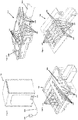
- a device connection terminal 102 is arranged on the rear of an oven 101. This device connection terminal 102 has contacts 107 for connecting the internal wiring of the device, insertion openings 106 assigned to these contacts 107 and assigned cage tension springs 110.
- the contacts 107 for connecting the internal wiring of the device are connected via wires (not shown) to an electrical component such as the heater, the fan and / or the light of the oven 101.
- the ends of the five wires 105 of the mains connection line 103 of the house are stripped. Three of the wires are called phase, one wire is called the neutral wire and one is called the earth.
- the stripped ends of the wires 105 are pushed in through the insertion openings 106 and positioned in relation to the contacts for connecting the internal wiring 107 of the device.
- the cage tension springs 110 are pressed downwards so that the stripped wires 105 can be inserted completely.
- the respective cage tension spring 110 "released" so that the stripped part of the wire 105 is connected to the contacts for connecting the internal wiring 107 of the device via an eyelet of the cage tension spring 110 with the corresponding tension spring force. This is done accordingly for all cores.
- a device connection terminal 202 has a network connection line 203.
- the mains connection line 203 is firmly clamped in the interior of the device connection terminal 202 by means of a retaining clip 204.
- a cable sheathing of the mains connection line 203 was removed behind the retaining clip 204, so that then five wires 205 of the mains connection line 203 are individually routed.
- the five wires 205 are each guided into a cage tension spring contact module 213 via an insertion opening 206.
- five conductors 217 of internal device wiring are guided into one of the five cage tension spring contact modules 213 by means of five insertion openings 203 (not shown).
- the device connection terminal 202 On the underside, the device connection terminal 202 has a protective conductor connection 218, which is connected to the device connection terminal 202 on the underside with a power contact clamping spring (not shown).
- Each cage tension spring contact module 213 has a movable module cover 215 and two opposite insertion openings 206.
- each A cage tension spring contact module 213 has a first cage tension spring 210 and a second cage tension spring 211 on a current bar 212 inside.
- the current bar 212 is made electrically conductive from copper with a silver surface.
- the mains connection line 203 is inserted into the device connection terminal 202 and clamped by means of the retaining clip 204 inside the device connection terminal 202. Behind the retaining clamp 204, the five wires 205 are routed individually, free of the cable sheathing of the mains connection line 203, inside the device connection terminal 202, each to one of the cage clamp spring contact modules 213. Likewise, the conductors 217 of the device's internal wiring in the device connection terminal 202 are each led individually to the corresponding cage clamp contact modules 213. The conductors 217 of the internal wiring of the device and the wires 205 of the mains connection line 203 are stripped at their respective free ends.
- the module covers 215 of the respective cage tension spring contact modules 213 are now closed one after the other by manually pressing the respective module cover 215. As a result, a pressure is applied to the first cage tension spring 210 and the second cage tension spring 211 from above and the two cage tension springs 210 and 211 are compressed.
- the recess 220, 221 shift from the top of the current bar 212 to the bottom of the current bar 212 through the opposite insertion openings 206 of each contact module 213 on one side a stripped wire 205 and on the other side a stripped conductor 217 of the device internal wiring through the insertion opening 206 and the recess 220 or 221 shifted downwards.
- the stripped wire 205 and the stripped conductor 217 are clamped to the underside of the current bar 212 with a defined contacting force due to the corresponding spring tension.
- the first cage tension spring 210 and the second cage tension spring 211 depending on the cross-sections of the stripped wire 205 and the stripped conductor 217, partly move to their relaxed position against the due to their spring force Module cover 315 back.
- the clamped stripped wire 205 and the clamped stripped conductor 217 are in electrical contact via the current bar 212.
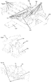
- a device connection terminal 302 has a mains connection line 303, a retaining clip 304, five conductor direct contact modules 313 and five conductors 317 of internal device wiring (in Figure 8 shown when not connected).
- the mains connection line 303 again has five wires 305 at its end, which are stripped at their ends so that individual strands are exposed.
- the conductors 317 are also stripped at their end.
- a protective conductor connection 318 is in turn arranged on the underside of the device connection terminal 302.
- Each conductor direct contact module 313 has an actuatable, movable module cover 315 and, on opposite sides, an insertion opening 306 for a wire 305 and a conductor 317.
- each direct conductor contact module 313 a line guiding and clamping element 314 with a central catch 311 is arranged.
- the line guiding and clamping element 314 has two recesses 320 on opposite sides for the implementation of the conductor 317 and the Core 305 (see Fig. 10 ), whereby the recess 320 for the conductor 317 of the internal wiring of the device is higher than the recess 320 for the core 305.
- This is realized by a corresponding design of the conductor guiding and clamping element 314 with a correspondingly higher guide track for the conductor 317.
- each direct conductor contact module 313 With the module cover 315 of each direct conductor contact module 313 open, the stripped wire 305 of the mains connection cable 303 is inserted into the one insertion opening 303 in the cable routing and clamping element 314 of the direct conductor contact module 313, so that the stripped wire 305 lies at the bottom in the cable routing and clamping element 314.
- the corresponding stripped conductor 317 is inserted into the line guiding and clamping element 314 through the opposite insertion opening 306, so that the stripped conductor 317 lies above the stripped wire 305. This is supported by the fact that the line guiding and clamping element 314 presses at its free ends with a respective clamping element from above onto the stripped wire 305 and the stripped conductor 317.
- the module cover 315 is then closed by manually pressing it on, whereby the module cover 315 presses from above against the catch 311, which in the middle area of the line guiding and clamping element 314, in which the stripped conductor 317 lies on the stripped wire 305, presses and engages on a corresponding snap-in hook (not shown) on the inside of the direct conductor module 313, so that a defined contacting force is applied to the direct electrical connection of the stripped wire 305 and the stripped conductor 317 is exerted due to their abutment.
- the conductor direct contact module 313 does not require any additional electrical connecting element and thus no special conductive materials such as copper or silver, which means that it is inexpensively manufactured from stamped and bent metal parts.
- the direct conductor contact module 313 minimizes transmission losses and thus a long-lasting device connection terminal 302 and a permanent direct electrical connection between the wires 305 of the mains connection line 303 and the corresponding lines 317 of the device's internal wiring are implemented.
- the direct conductor contact module has a single cage tension spring 210 or 211 (cf. in Fig. 7 ) without a current bar.
- the cage tension spring 210 or 211 is compressed and passed through the recess 220 or 221, which is now below the lower horizontal section (which is shown in FIG Fig. 7 rests on the current bar 212) the cage tension spring 210 or 211 is, a bare conductor 317 is from one side of the Internal wiring of the device and a bare wire 305 from the other side.
- the bare conductor 317 of the internal wiring of the device and the bare wire 305 are on top of each other and are clamped by means of the lower horizontal section of the cage tension spring 210 or 211, which is passed through the recess 220 or 221, so that there is direct contact between the bare wire 305 and the bare conductor 317 of the device internal wiring is made.
Landscapes
- Details Of Connecting Devices For Male And Female Coupling (AREA)
- Connector Housings Or Holding Contact Members (AREA)
Description
Die Erfindung betrifft eine Geräteanschlusseinheit für ein Elektrogerät mit wenigstens zwei Geräteversorgungselementen zum Versorgen von elektrischen Bauteilen des Elektrogerätes mit elektrischer Energie. Des Weiteren betrifft die Erfindung ein Elektrogerät.The invention relates to a device connection unit for an electrical device with at least two device supply elements for supplying electrical components of the electrical device with electrical energy. The invention also relates to an electrical device.
Elektrische Geräte benötigen für ihre Funktion elektrische Energie mit einer Versorgungsspannung von unter oder über 250 V, wobei Haushaltsgeräte, wie beispielsweise Kochfelder und Backöfen, eine Betriebsspannung von über 250 V erfordern.Electrical devices require electrical energy with a supply voltage of less than or more than 250 V to function, with household devices such as hobs and ovens, for example, requiring an operating voltage of more than 250 V.
Um diese Energieversorgung sicherstellen zu können, müssen die Geräte sicher mit dem Gebäudeinstallationsnetz verbunden werden.In order to be able to ensure this energy supply, the devices must be securely connected to the building installation network.
Geräteseitig geschieht dies meist durch das Anschließen einer Netzleitung mit entsprechendem Querschnitt an das im Gerät eingebaute Anschlussterminal sowie netzseitig durch das Anschließen dieser Netzleitung an eine Geräteanschlussdose der Hauselektroinstallation. Bei Geräten unter 250 V Versorgungsspannung wird anstelle des Anschlussterminals üblicherweise ein Geräteanschlusssystem oder ein Geräteanschlussstecker verwendet.On the device side, this is usually done by connecting a power line with the appropriate cross-section to the connection terminal built into the device and, on the network side, by connecting this power line to a device connection socket of the house electrical installation. For devices with a supply voltage of less than 250 V, a device connection system or a device connection plug is usually used instead of the connection terminal.
Problematisch dabei ist, dass der Anschluss der Netzleitung an die Geräteanschlusseinheit und/oder an die Geräteanschlussdose der Hauselektroinstallation nach dem Stand der Technik über Schraubklemmen erfolgt. Hierzu werden beispielsweise die abisolierten Adern mit einer Aderendhülse versehen und die so konfektionierten Aderenden der Netzleitung werden mittels jeweils einer Schraube auf eine Kontaktklemme montiert, wobei letztere über Steckkontakte mit der Geräteinnenverdrahtung verbunden ist.The problem here is that the power line is connected to the device connection unit and / or to the device connection box of the house electrical installation according to the prior art using screw terminals. For this purpose, for example, the stripped wires are provided with a wire end sleeve and the wire ends of the power line assembled in this way are each mounted on a contact terminal by means of a screw, the latter being connected to the internal wiring of the device via plug contacts.
Nachteilig hierbei ist, dass dieser Anschluss sehr montage- und materialaufwändig von einem Elektrofachmann oder zumindest einer elektrotechnisch unterwiesenen Person vor Ort hergestellt werden muss.The disadvantage here is that this connection has to be made on site by a qualified electrician or at least a person who has been trained in electrical engineering, which is very expensive to assemble and use.
Die Schwierigkeit besteht insbesondere darin, dass eine mittels Schraubklemme ausgeführte elektrische Verbindung nur dann langfristig elektrisch sicher funktionieren kann, wenn die Schraube exakt mit der vom Hersteller vorgegebenen Schraubenvorspannkraft angezogen wird.The particular problem is that an electrical connection made by means of a screw terminal can only function safely and reliably in the long term if the screw is tightened precisely with the screw pretensioning force specified by the manufacturer.
Diese exakt notwendige Schraubenvorspannkraft einzustellen, stellt nach dem Stand der Technik eine Herausforderung dar, welche nur über die mechanische Hilfsgröße Drehmoment mit einer sehr großen Ungenauigkeit realisiert werden kann.Setting this precisely required screw pretensioning force represents a challenge according to the state of the art, which can only be implemented with a very high degree of inaccuracy using the mechanical auxiliary variable torque.
Dazu ist es notwendig, ein kalibriertes drehmomentgesteuertes Schraubwerkzeug zu verwenden. Jedoch ist dieses bereits in einem industriellen Fertigungsprozess kaum sicher im Dauerbetrieb anwendbar. Umso unsicherer und unwahrscheinlicher ist dessen sichere, exakte und selbstverständliche Anwendung in einem handwerklich geprägten Serviceeinsatz, wie der Inbetriebnahme eines weißen Ware-Gerätes. Praktisch werden hier meist die Schrauben der Schraubverbindung auf gut Glück angezogen, ohne die geforderten Schraubenvorspannkräfte zu kennen, gezielt einzustellen und/oder gar einzuhalten.To do this, it is necessary to use a calibrated torque-controlled screwdriver. However, this can hardly be safely used in continuous operation in an industrial manufacturing process. All the more insecure and It is less likely that it will be used safely, precisely and as a matter of course in a manual service operation, such as the commissioning of a white goods device. In practice, the screws of the screw connection are here mostly tightened by chance, without knowing the required screw pretensioning forces, setting them in a targeted manner and / or even maintaining them.
Aus dieser üblichen Praxis ergibt sich ein erhöhtes Fehlerpotential für die Elektrosicherheit des Geräteanwenders und des Gerätes sowie eine erhöhte Brandgefahr durch thermisch überlastete Verbindungsstellen.This common practice results in an increased fault potential for the electrical safety of the device user and the device as well as an increased risk of fire due to thermally overloaded connection points.
Des Weiteren benötigt die Schraubverbindung entsprechende zusätzliche Verbindungsbauteile, wodurch sich die Übertragungsverluste zwischen Netz und Gerät aufgrund zusätzlicher Durchgangs- und/oder Übergangswiderstände erhöhen. Zudem benötigt diese Schraubverbindungstechnik hochwertige und/oder leitfähige Werkstoffe und Materialien zur Herstellung der elektrischen Verbindung. Dies ist insbesondere auch im Hinblick auf die zunehmenden hohen Materialpreise, langen Lieferzeiten von entsprechenden Bauteilen und die allgemeine Verknappung von Rohstoffen nachteilig.Furthermore, the screw connection requires corresponding additional connection components, which increases the transmission losses between the network and the device due to additional contact and / or contact resistances. In addition, this screw connection technology requires high-quality and / or conductive materials for making the electrical connection. This is particularly disadvantageous with regard to the increasing high material prices, long delivery times for corresponding components and the general shortage of raw materials.
Aus der
In der
Aus der
Die
Aufgabe der Erfindung ist es, den Stand der Technik zu verbessern.The object of the invention is to improve the state of the art.
Gelöst wird die Aufgabe durch eine Geräteanschlusseinheit für ein Elektrogerät mit wenigstens zwei Geräteversorgungselementen zum Versorgen von elektrischen Bauteilen des Elektrogerätes mit elektrischer Energie, wobei den Geräteversorgungselementen jeweils ein Kontaktierungselement zugeordnet ist, welches jeweils einem angeordneten Versorgungsleiter im Betätigungsfall eine definierte Kontaktierungskraft mittels eines Beaufschlagungselementes aufprägt, sodass ein elektrischer Kontakt zwischen den jeweiligen Geräteversorgungselement und dem Versorgungsleiter realisiert ist, wobei die Kontaktierungselemente ein Betätigungselement aufweisen, sodass durch ein Betätigen des Betätigungselementes die Kontaktierungskraft verstärkt oder verringert wird und die Beaufschlagungselemente ein Federelement, ein Klemmelement und/oder ein Rastelement aufweisen, welches jeweils die definierte Kontaktierungskraft aufprägt.The object is achieved by a device connection unit for an electrical device with at least two device supply elements for supplying electrical components of the electrical device with electrical energy, the device supply elements each being assigned a contacting element which, in the event of actuation, impresses a defined contacting force on an arranged supply conductor in the event of actuation, so that an electrical contact is realized between the respective device supply element and the supply conductor, the contacting elements having an actuating element, so that the contacting force is increased or reduced by actuating the actuating element and the actuating elements have a spring element, a clamping element and / or a latching element, which in each case the defined contact force impresses.
Somit wird eine montagefreundliche und materialsparende elektrische Verbindung zwischen dem jeweiligen Geräteversorgungselement und dem Versorgungsleiter des Netzanschlusses realisiert, ohne dass aufwändige Zusatzwerkzeuge zur Herstellung der Verbindung notwendig sind.An assembly-friendly and material-saving electrical connection between the respective device supply element and the supply conductor of the network connection is thus achieved without the need for complex additional tools to establish the connection.
Es ist besonders vorteilhaft, dass der elektrische Kontakt zwischen dem jeweiligen Geräteversorgungselement und dem Versorgungsleiter frei von einer Schraubverbindung mit zusätzlichen Verbindungsbauteilen ist, wodurch Übertragungsverluste zwischen dem Netz und dem Elektrogerät, die Fehleranfälligkeit und/oder die Brandgefahr verringert werden.It is particularly advantageous that the electrical contact between the respective device supply element and the supply conductor is free of a screw connection with additional connecting components, which reduces transmission losses between the network and the electrical device, the susceptibility to errors and / or the risk of fire.
Zudem kann auf hochwertige zusätzliche Werkstoffe und Materialien zum Ausbilden des elektrischen Kontaktes zwischen dem jeweiligen Geräteversorgungselement und dem Versorgungsleiter des Versorgungsnetzes verzichtet werden.In addition, high-quality additional materials for forming the electrical contact between the respective device supply element and the supply conductor of the supply network can be dispensed with.
Somit wird eine sichere, verlustarme Verbindung des Elektrogeräts zum jeweiligen länderspezifischen Versorgungsnetz bereitgestellt.This provides a secure, low-loss connection between the electrical device and the respective country-specific supply network.
Des Weiteren können nun auch Nicht-Fachleute beispielsweise ein derartiges Haushaltsgerät sicher an das Hausnetz anschließen, wobei dieses auch frei von Werkzeugen erfolgt. Folglich ist ein Drehmomentschlüssel zum sicheren Kontaktieren vorliegend nicht mehr notwendig.Furthermore, non-specialists can now, for example, safely connect such a household appliance to the house network, this also being done without tools. As a result, a torque wrench is no longer necessary in the present case for secure contact.
Ein wesentlicher Gedanke der Erfindung beruht darauf, dass der elektrische Kontakt über ein Kontaktierungselement erfolgt, welches durch Ausgestaltung eines Beaufschlagungselementes eine definierte Kontaktierungskraft im Betätigungsfall auf den Versorgungsleiter ausübt. Somit wird mittels des Beaufschlagungselementes gezielt und definiert die Kontaktierungskraft bereit- und/oder eingestellt, indem das Beaufschlagungselement zumindest auf jeweils einen angeordneten Versorgungsleiter einwirkt.An essential idea of the invention is based on the fact that the electrical contact takes place via a contacting element which, by designing a loading element, exerts a defined contacting force on the supply conductor when it is actuated. Thus, by means of the loading element, the contacting force is prepared and / or set in a targeted and defined manner, in that the loading element acts on at least one arranged supply conductor in each case.
Folgendes Begriffliche sei erläutert:
- Eine "Geräteanschlusseinheit" ist insbesondere ein Geräteanschlussterminal, eine Geräteanschlussdose, ein Geräteanschlusssystem oder ein Geräteanschlussstecker. Eine Geräteanschlusseinheit stellt insbesondere eine elektrische Verbindung zwischen der Geräteinnenverdrahtung des Elektrogerätes und den Versorgungsleitern des Netzanschlusses (Stromnetz) dar.
- Ein "Elektrogerät" ist ein durch elektrische Energie betriebenes Gerät für private und/oder gewerbliche Nutzung. Das Elektrogerät wird insbesondere direkt vom Stromnetz mit Energie versorgt. Ein Elektrogerät ist beispielsweise eine Lötstation, ein medizinisches Gerät oder ein Haushaltsgerät. Bei einem "Haushaltsgerät" handelt es sich insbesondere um ein elektrisches Gerät, welches üblicherweise im Privathaushalt genutzt wird. Unter ein Haushaltsgerät fallen beispielsweise ein Elektroherd, eine Geschirrspülmaschine oder eine Waschmaschine. Ein Haushaltsgerät wird insbesondere auch als Weiße Ware bezeichnet.
- Ein "Geräteversorgungselement" ist insbesondere ein Element in der Geräteanschlusseinheit, welches im Kontakt zur Geräteinnenverdrahtung des Elektrogerätes steht. Ein Geräteversorgungselement kann beispielsweise als fester und/oder unflexibler Kontakt oder als Leiter ausgeführt sein. Zum Beispiel ist ein Geräteversorgungselement eine Leiterlitze eines Kabelbaumes der Geräteinnenverdrahtung oder ein Anschlusspin eines Leuchtmittels. Ist das Geräteversorgungselement beispielsweise eine Litze als Bestandteil einer Innenverdrahtung, so ist diese Litze entsprechend flexibel.
- Ein "Versorgungsleiter" ist insbesondere ein stromführender Leiter (auch "Ader" genannt) in einem Netzkabel. Der Versorgungsleiter ist insbesondere mit einer Isolierung umhüllt, jedoch insbesondere im Bereich des elektrischen Kontaktes abisoliert, sodass freier ("blanker") Draht und/oder freie Litzen an der Stelle des elektrischen Kontaktes vorliegt oder vorliegen. Hierbei ist es entscheidend, dass der blanke Leiter der Netzleitung direkt, das bedeutet ohne ein zusätzliches Kontaktelement, wie beispielsweise 6,3 mm Flachsteckkontakt, mit dem Geräteversorgungselement verbunden ist. Der Draht oder die Litzen des Versorgungsleiters weist oder weisen insbesondere Kupfer oder Aluminium auf.
- Unter einem "elektrischen Kontakt" wird eine leitende elektrische Verbindung zwischen dem jeweiligen Geräteversorgungselement und dem Versorgungsleiter verstanden. Der elektrische Kontakt besteht insbesondere direkt, das bedeutet, der abisolierte Versorgungsleiter steht in direkter mechanischer Verbindung zum Geräteversorgungselement, oder indirekt, wobei bei letzterem der elektrische Kontakt über ein zusätzlich stromleitendes Verbindungselement erfolgt, sodass sich Geräteversorgungselement und Versorgungsleiter nicht direkt berühren.
- Ein "Kontaktierungselement" ist insbesondere ein Element oder Bauteil, welches den elektrischen Kontakt zwischen dem jeweiligen Geräteversorgungselement und dem Versorgungsleiter herstellt oder diese in einen elektrischen Kontakt bringt. Bei einem Kontaktierungselement kann es sich beispielsweise um ein Käfigzugfederkontaktmodul oder ein Leiterdirektverbindungskontaktmodul handeln.
- Ein "Beaufschlagungselement" ist ein Element des Kontaktierungselementes, welches zumindest dem Versorgungsleiter im Betätigungsfall eine definierte Kontaktierungskraft aufprägt.
- Unter einer "definierten Kontaktierungskraft" wird insbesondere eine Kraft verstanden, mit welcher der Versorgungsleiter und/oder das Geräteversorgungselement in der Geräteanschlusseinheit in eine elektrische Verbindung gebracht werden. Die definierte Kontaktierungskraft wird insbesondere auf die elektrische Verbindung zwischen dem Geräteversorgungselement und dem Versorgungsleiter und/oder einem weiteren Verbindungselement aufgebracht. Somit liegt der Betätigungsfall und/oder ein Wirkungsfall vor.
- A “device connection unit” is in particular a device connection terminal, a device connection socket, a device connection system or a device connection plug. A device connection unit is in particular an electrical one Connection between the internal wiring of the electrical device and the supply conductors of the mains connection (mains).
- An "electrical device" is a device operated by electrical energy for private and / or commercial use. In particular, the electrical device is supplied with energy directly from the power grid. An electrical device is, for example, a soldering station, a medical device or a household device. A “household appliance” is, in particular, an electrical appliance that is usually used in private households. A household appliance includes, for example, an electric stove, a dishwasher or a washing machine. A household appliance is also referred to in particular as white goods.
- A “device supply element” is in particular an element in the device connection unit which is in contact with the internal wiring of the electrical device. A device supply element can, for example, be designed as a fixed and / or inflexible contact or as a conductor. For example, a device supply element is a stranded conductor of a cable harness of the device's internal wiring or a connection pin of a light source. If the device supply element is, for example, a stranded wire as part of internal wiring, then this stranded wire is correspondingly flexible.
- A "supply conductor" is in particular a current-carrying conductor (also called a "wire") in one Power cord. The supply conductor is in particular sheathed with insulation, but stripped in particular in the area of the electrical contact, so that free ("bare") wire and / or free strands are or are present at the point of the electrical contact. It is crucial here that the bare conductor of the mains cable is connected directly to the device supply element, i.e. without an additional contact element, such as a 6.3 mm blade terminal contact. The wire or the strands of the supply conductor has or have in particular copper or aluminum.
- An "electrical contact" is understood to mean a conductive electrical connection between the respective device supply element and the supply conductor. The electrical contact is particularly direct, that is, the stripped supply conductor is in direct mechanical connection to the device supply element, or indirectly, with the latter making electrical contact via an additional current-conducting connection element, so that the device supply element and supply conductor do not touch each other directly.
- A “contacting element” is, in particular, an element or component which establishes the electrical contact between the respective device supply element and the supply conductor or brings them into electrical contact. A contacting element can be, for example, a Act cage-clamp spring contact module or a direct conductor connection contact module.
- A "loading element" is an element of the contacting element which applies a defined contacting force to at least the supply conductor when it is actuated.
- A “defined contacting force” is understood to mean, in particular, a force with which the supply conductor and / or the device supply element are brought into electrical connection in the device connection unit. The defined contacting force is applied in particular to the electrical connection between the device supply element and the supply conductor and / or a further connecting element. The case of actuation and / or an effect case is thus present.
In einer weiteren Ausführungsform weist die Geräteanschlusseinheit drei, vier, fünf, sechs oder weitere Geräteversorgungselemente auf, welchen jeweils ein Kontaktierungselement zugeordnet ist, welches jeweils einem angeordneten Versorgungsleiter im Betätigungsfall eine definierte Kontaktierungskraft mittels jeweils einem Beaufschlagungselement aufprägt.In a further embodiment, the device connection unit has three, four, five, six or further device supply elements, each of which is assigned a contacting element that applies a defined contacting force to an arranged supply conductor in the event of actuation by means of a respective loading element.
Somit ist je nach Anzahl der Adern des Netzkabels aufgrund von Gleichstrom, Wechsel- oder Drehstrom sowie der entsprechenden Schutzklasse jeder Versorgungsleiter (Ader des Netzkabels) mittels eines zugeordneten Kontaktierungselementes mit einem Beaufschlagungselement elektrisch mit dem jeweils zugeordneten Geräteversorgungselement verbindbar.Thus, depending on the number of wires in the power cable, due to direct current, alternating current or three-phase current and the corresponding protection class, each supply conductor (wire of the power cable) is connected to an impingement element by means of an associated contacting element electrically connectable to the respectively assigned device supply element.
Hierbei kann bei jedem Kontaktierungselement aufgrund der Ausgestaltung seines jeweiligen Beaufschlagungselementes dieselbe definierte Kontaktierungskraft bei allen Kontaktierungselementen oder unterschiedliche definierte Kontaktierungskräfte aufgeprägt werden. Somit kann beispielsweise gezielt die definierte Kontaktierungskraft an den Durchmesser von unterschiedlich dicken Versorgungsleitern angepasst werden.In this case, the same defined contacting force can be applied to all contacting elements or different defined contacting forces can be applied to each contacting element due to the design of its respective loading element. Thus, for example, the defined contacting force can be specifically adapted to the diameter of supply conductors of different thicknesses.
Besonders vorteilhaft ist es, wenn die Geräteversorgungselemente als im Wesentlichen stabile Stege ausgestaltet sind. Während somit übliche Versorgungsleiter aufgrund ihres Aderquerschnitts eine gewisse Flexibilität bieten, ist die stabile und somit feste Ausgestaltung der Geräteversorgungselemente dafür geeignet, dass bei den durch die Kontaktierungselemente über den Versorgungsleiter aufgeprägten Kräften die Geräteversorgungselemente sich nicht verbiegen. Somit bieten die als im Wesentlichen stabile Stege ausgestalteten Versorgungselemente einen Kraftwiderstand gegen die aufgeprägten Kontaktierungskräfte auf die Versorgungsleiter.It is particularly advantageous if the device supply elements are designed as essentially stable webs. While conventional supply conductors thus offer a certain flexibility due to their core cross-section, the stable and thus solid design of the device supply elements is suitable for ensuring that the device supply elements do not bend under the forces exerted by the contacting elements via the supply conductor. The supply elements, which are designed as essentially stable webs, thus offer a force resistance against the contacting forces applied to the supply conductors.
Um die definierte Kontaktierungskraft gezielt einzustellen und/oder um eine sich selbst nachregelnde elektrische Verbindungstechnik bereitzustellen, weisen die Beaufschlagungselemente ein Federelement, ein Klemmelement und/oder ein Rastelement auf, welches jeweils die definierte Kontaktierungskraft aufprägt.In order to set the defined contacting force in a targeted manner and / or to provide a self-adjusting electrical connection technology, the loading elements have a spring element, a clamping element and / or a latching element, each of which impresses the defined contacting force.
Somit kann die auf den Versorgungsleiter wirkende notwendige Kontaktierungskraft gezielt mittels der Ausgestaltung des Federelementes, des Klemmelementes und/oder des Rastelementes eingestellt, verändert und/oder langfristig gehalten werden.Thus, the necessary contacting force acting on the supply conductor can be set, changed and / or maintained for a long time in a targeted manner by means of the design of the spring element, the clamping element and / or the latching element.
Ein "Federelement" ist insbesondere ein metallisches technisches Bauteil, welches sich elastisch verformen lässt. Ein Federelement ist insbesondere eine Schraubfeder, beispielsweise ein in Schraubenform gewickelter Draht. Hierbei lässt sich die Kontaktierungskraft insbesondere über die Federkonstante (Federhärte) des Federelementes einstellen. Bei dem Federelement können insbesondere der Werkstoff, die Anzahl und der Durchmesser der Wicklungen variiert werden, um eine definierte Kontaktierungskraft einzustellen. Bei Einwirken und/oder Betätigen der Feder tritt als elastische Verformung insbesondere eine Dehnung, Biegung, Scherung und/oder Torsion auf.A “spring element” is in particular a metallic technical component which can be elastically deformed. A spring element is in particular a helical spring, for example a wire wound in a helical shape. Here, the contacting force can be adjusted in particular via the spring constant (spring hardness) of the spring element. In the case of the spring element, in particular the material, the number and the diameter of the windings can be varied in order to set a defined contacting force. When the spring acts and / or is actuated, elastic deformation occurs in particular as stretching, bending, shearing and / or torsion.
Ein "Klemmelement" ist insbesondere ein Bauteil, welches geometrisch derart ausgestaltet ist, dass bei Anbringen an den Versorgungsleiter dieser mechanisch fixiert wird. Dazu weist das Klemmelement beispielsweise eine kleiner werdende Aussparung auf, in welche der Versorgungsleiter mechanisch fixiert wird.A “clamping element” is in particular a component which is geometrically designed in such a way that when it is attached to the supply conductor, the latter is mechanically fixed. For this purpose, the clamping element has, for example, a recess that is becoming smaller, in which the supply conductor is mechanically fixed.
Ein "Rastelement" (auch "Verrastelement") ist insbesondere ein Bauteil, welches beim Verschieben in eine vorgegebene Position einrastet und dadurch eine Presskraft auf den Versorgungsleiter ausübt. Beispielsweise wird durch ein vertikales Verschieben und dadurch realisiertes Einrasten eine vertikale Presskraft auf den Versorgungsleiter ausgeübt. Bevorzugt weist das Kontaktierungselement mehrere Einraststufen des Rastelementes auf, sodass die Presskraft und somit die Kontaktierungskraft gezielt eingestellt und/oder angepasst werden kann. Beispielsweise erfolgt das Einrasten des Rastelementes im Inneren des Kontaktierungselementes an verschiedenen Rasthaken der inneren Gehäusewand des Kontaktierungselementes. Auch kann beispielsweise das Rastelement als Bügel ausgestaltet sein, welcher durch ein Schwenken in eine Rastposition verfährt und dabei den Versorgungsleiter mit dem entsprechenden Geräteversorgungselement zusammenpresst.A “latching element” (also “latching element”) is in particular a component which latches when it is moved into a predetermined position and thereby exerts a pressing force on the supply conductor. For example, by a vertical shift and thereby realized Snapping into place exerts a vertical compressive force on the supply ladder. The contacting element preferably has several latching steps of the latching element, so that the pressing force and thus the contacting force can be set and / or adapted in a targeted manner. For example, the latching element engages in the interior of the contacting element on different latching hooks on the inner housing wall of the contacting element. The latching element can also be designed as a bracket, for example, which moves into a latching position by pivoting and thereby presses the supply conductor with the corresponding device supply element.
In einer weiteren Ausführungsform der Geräteanschlusseinheit ist dem Geräteversorgungselementen und/oder den Versorgungsleitern jeweils eine Einführeinrichtung zugeordnet, sodass das jeweilige Geräteversorgungselement und der jeweilige Versorgungsleiter definiert zueinander anordenbar sind.In a further embodiment of the device connection unit, the device supply elements and / or the supply conductors are each assigned an insertion device, so that the respective device supply element and the respective supply conductor can be arranged in a defined manner with respect to one another.
Dadurch können sowohl die Geräteversorgungselemente als auch die Versorgungsleiter jeweils durch eine Einführeinrichtung in das Kontaktierungselement eingebracht und/oder durch die Einführungseinrichtung im Inneren des Kontaktierungselementes derart geführt werden, dass diese jeweils eine definierte Anordnung im Kontaktierungselement und zueinander einnehmen.As a result, both the device supply elements and the supply conductors can each be introduced into the contacting element through an insertion device and / or guided through the insertion device inside the contacting element in such a way that they each occupy a defined arrangement in the contacting element and with respect to one another.
Eine "Einführeinrichtung" ist insbesondere eine Einrichtung, welche ein gezieltes Einführen und somit Einbringen eines Geräteversorgungselementes und/oder Versorgungsleiters in die Geräteanschlusseinheit und/oder das Kontaktierungselement ermöglicht und/oder das Geräteversorgungselement und/oder den Versorgungsleiter innerhalb der Geräteanschlusseinheit und/oder des Kontaktierungselementes gezielt in seinem jeweiligen Verlauf führt. Bei einer Einführeinrichtung kann es sich insbesondere um eine Einführöffnung und/oder um eine ausgeführte Führungsbahn der Geräteanschlusseinheit und/oder des Kontaktierungselements handeln.An “insertion device” is, in particular, a device which enables targeted insertion and thus Bringing a device supply element and / or supply conductor into the device connection unit and / or the contacting element enables and / or guides the device supply element and / or the supply conductor specifically in its respective course within the device connection unit and / or the contacting element. An insertion device can in particular be an insertion opening and / or an implemented guide track of the device connection unit and / or of the contacting element.
Um die Kontaktierungskraft gezielt einzustellen und/oder anzupassen, weisen die Kontaktierungselemente ein Betätigungselement auf, sodass durch ein Betätigen des Betätigungselements die Kontaktierungskraft verstärkt oder verringert wird.In order to set and / or adapt the contacting force in a targeted manner, the contacting elements have an actuating element so that the contacting force is increased or decreased by actuating the actuating element.
Bei einem "Betätigungselement" handelt es sich insbesondere um ein mechanisch betätigtes Bauelement, welches auf das Beaufschlagungselement einwirkt und dadurch die Kontaktierungskraft verändert. Bei einem Betätigungselement kann es sich beispielsweise um einen mechanischen und/oder elektronischen Schalter handeln. Auch kann das Betätigungselement als Abdeckung (Deckel) des Kontaktierungselements ausgebildet sein, sodass beispielsweise bei geöffneter Abdeckung das Beaufschlagungselement entlastet ist und das Geräteversorgungselement und/oder der Versorgungsleiter durch ein Einführloch in das Kontaktierungselement eingeführt werden können und beim anschließenden Schließen der Abdeckung des Kontaktierungselementes durch direktes Einwirken der Abdeckung auf das Beaufschlagungselement eine definierte Kontaktierungskraft eingestellt wird. Beispielsweise drückt hierzu die Abdeckung und/oder das Betätigungselement direkt auf das Federelement und/oder das Rastelement beim Schließen des Kontaktierungselementes.An “actuating element” is, in particular, a mechanically actuated component which acts on the impingement element and thereby changes the contacting force. An actuating element can be, for example, a mechanical and / or electronic switch. The actuating element can also be designed as a cover (cover) of the contacting element so that, for example, when the cover is open, the loading element is relieved and the device supply element and / or the supply conductor can be inserted through an insertion hole into the contacting element and, when the cover of the contacting element is subsequently closed, by direct Action of the cover on the loading element a defined contacting force is set. For example, for this purpose the cover and / or the actuating element presses directly on the spring element and / or the latching element when the contacting element is closed.
Das Kontaktierungselement ist derart eingerichtet, dass jeweils dem angeordneten Versorgungsleiter und dem jeweiligen Leiter im Betätigungsfall die definierte Kontaktierungskraft mittels des Beaufschlagungselementes aufgeprägt wird.The contacting element is set up in such a way that the defined contacting force is impressed on the arranged supply conductor and the respective conductor when actuated by means of the loading element.
Somit können simultan dem jeweiligen Leiter der Gehäuseinnenverdrahtung des Elektrogerätes und dem zugeordnete Versorgungsleiter in einem Kontaktierungselement eine definierte Kontaktierungskraft aufgeprägt werden. Je nach Ausgestaltung des Kontaktierungselementes, beispielsweise mit einer Feder oder mit jeweils zwei getrennten Federn jeweils für den Leiter der Geräteinnenverdrahtung und dem Versorgungsleiter, kann somit dieselbe Kontaktierungskraft oder unterschiedliche Kontaktierungskräfte aufgebracht werden.A defined contacting force can thus be simultaneously impressed on the respective conductor of the internal wiring of the housing of the electrical device and the associated supply conductor in a contacting element. Depending on the design of the contacting element, for example with a spring or with two separate springs each for the conductor of the device internal wiring and the supply conductor, the same contacting force or different contacting forces can thus be applied.
Um die notwendige Kontaktierungskraft mittels der Ausgestaltung des Kontaktierungselementes einzustellen, weist oder weisen eines der Kontaktierungselemente oder mehrere Kontaktierungselemente oder sämtliche Kontaktierungselemente eine Käfigzugfeder auf.In order to set the necessary contacting force by means of the configuration of the contacting element, one of the contacting elements or a plurality of contacting elements or all of the contacting elements has a cage tension spring.
Wenn der Leiter der Geräteinnenverdrahtung und der zugeordnete Versorgungsleiter einen unterschiedlichen Aderquerschnitt aufweisen, ist es besondere vorteilhaft, wenn das Kontaktierungselement zwei unterschiedliche Käfigzugfedern aufweist, sodass in Abhängigkeit des Aderquerschnittes unterschiedliche definierte Kontaktierungskräfte auf den Leiter und den Versorgungsleiter aufgebracht werden können.If the conductor of the device's internal wiring and the assigned supply conductor have a different wire cross-section, it is particularly advantageous if the contacting element has two different cage tension springs so that different defined contacting forces can be applied to the conductor and the supply conductor depending on the wire cross-section.
Bei einer "Käfigzugfeder" handelt es sich insbesondere um einen Federklemmanschluss für eine elektrische Verbindung. Eine Käfigzugfeder weist insbesondere einen Grob- und/oder Mittel-Federstahl auf. Die Käfigzugfeder weist insbesondere eine Klemmfeder und/oder eine Stromschiene (Strombalken) auf. Der Strombalken besteht insbesondere aus Kupfer mit einer Silberoberfläche. Die Klemmfeder wird insbesondere durch das Betätigungselement zusammengedrückt, wodurch der Leiter und/oder Versorgungsleiter in die Aussparung der Klemmfeder unterhalb des Strombalkens einführbar ist und beim Entlasten der Klemmfeder diese in ihre Ruhelage zurückkehrt, sodass durch die Klemm- oder Kontaktkraft der Leiter und/oder Versorgungsleiter von unten gegen den Strombalken gepresst wird. Somit wird ein elektrischer Kontakt zwischen dem Leiter und/oder dem Versorgungsleiter und dem Strombaken der Käfigzugfeder aufgebaut. Im Falle, dass auf beiden Seiten des Strombalkens eine Klemmfeder mit jeweils einem eingeklemmten Leiter der Geräteinnenverdrahtung und einem eingeklemmten Versorgungsleiter angeordnet ist, wird ein indirekter elektrischer Kontakt zwischen dem Leiter und dem Versorgungsleiter über den Strombalken der Käfigzugfeder realisiert. Mittels einer einzigen Käfigzugfeder kann jedoch auch ein direkter Kontakt zwischen dem Leiter und dem Versorgungsleiter hergestellt werden, in dem auf dem Strombalken verzichtet wird, und bei zusammengedrückter Käfigzugfeder von der einen Seite der Versorgungsleiter und darüber liegend von der anderen Seite der Leiter (oder umgekehrt) in die Aussparung der Käfigzugfeder eingebracht und eingeklemmt werden.A “cage clamp spring” is, in particular, a spring clamp connection for an electrical connection. A cage tension spring has, in particular, a coarse and / or medium spring steel. The cage tension spring has in particular a clamping spring and / or a busbar (current bar). The current bar consists in particular of copper with a silver surface. The clamping spring is compressed in particular by the actuating element, whereby the conductor and / or supply conductor can be inserted into the recess of the clamping spring below the current bar and when the clamping spring is relieved, it returns to its rest position, so that the conductor and / or supply conductor due to the clamping or contact force is pressed from below against the current bar. An electrical contact is thus established between the conductor and / or the supply conductor and the current hook of the cage clamp spring. In the event that a clamping spring is arranged on both sides of the current bar, each with a clamped conductor of the device internal wiring and a clamped supply conductor, an indirect one is used electrical contact between the conductor and the supply conductor is realized via the current bar of the cage clamp spring. However, a single cage clamp spring can also be used to establish direct contact between the conductor and the supply conductor, in which the current bar is dispensed with, and when the cage clamp spring is compressed from one side of the supply conductor and on top of it from the other side of the conductor (or vice versa) be introduced into the recess of the cage tension spring and clamped.
In einer weiteren Ausgestaltungsform der Geräteanschlusseinheit ist oder sind eins der Kontaktierungselemente oder mehrere Kontaktierungselemente oder sämtliche Kontaktierungselemente als Leiterdirektverbindungskontaktmodul ausgebildet, sodass mittels der definierten Kontaktierungskraft des Beaufschlagungselementes eine direkte elektrische Verbindung zwischen dem jeweiligen Geräteversorgungselement und dem Leiter und dem jeweiligen Versorgungsleiter besteht.In a further embodiment of the device connection unit, one of the contacting elements or several contacting elements or all contacting elements is or are designed as a direct conductor connection contact module, so that a direct electrical connection exists between the respective device supply element and the conductor and the respective supply conductor by means of the defined contacting force of the impingement element.
Ein "Leiterdirektverbindungskontaktmodul" ist insbesondere ein Bauteil, welches derart eingerichtet ist, dass die abisolierten Adern und/oder Litzen des Leiters und des Versorgungsleiters mittels des Leiterdirektverbindungskontaktmoduls direkt einen elektrischen Kontakt ausbilden, wodurch eine direkte elektrische Verbindung besteht.A "conductor direct connection contact module" is in particular a component which is set up in such a way that the stripped wires and / or strands of the conductor and the supply conductor directly form an electrical contact by means of the conductor direct connection contact module, whereby a direct electrical connection is established.
Um eine optimale direkte elektrische Verbindung zwischen dem Leiter und dem Versorgungsleiter herzustellen, weist das Leiterdirektverbindungskontaktmodul ein Leiterführungselement und/oder Leiterklemmelement auf.In order to establish an optimal direct electrical connection between the conductor and the supply conductor, the conductor direct connection contact module has a conductor guide element and / or conductor clamping element.
Somit wird der Leiter und der Versorgungsleiter mittels des Leiterführungselements und/oder Leiterklemmelementes derart geführt und in Position gebracht, dass die abisolierten Teile des Leiters und/oder des Versorgungsleiters in direktem mechanischen Kontakt innerhalb des Leiterdirektverbindungskontaktmoduls treten.Thus, the conductor and the supply conductor are guided and brought into position by means of the conductor guide element and / or conductor clamping element in such a way that the stripped parts of the conductor and / or the supply conductor come into direct mechanical contact within the conductor direct connection contact module.
Da im Falle des Leiterdirektverbindungskontaktmoduls eine direkte elektrische Verbindung zwischen dem Leiter und dem Versorgungsleiter auftritt, sind weitere stromführende Teile, wie ein Strombalken, in dieser Ausführungsform nicht notwendig. Folglich werden Übertragungsverluste minimiert und auf hochwertige, leitfähige Werkstoffe, wie die eines Strombalkens, kann beim Leiterdirektverbindungskontaktmodul verzichtet werden.Since, in the case of the direct connection contact module, there is a direct electrical connection between the conductor and the supply conductor, further current-carrying parts, such as a current bar, are not necessary in this embodiment. As a result, transmission losses are minimized and high-quality, conductive materials, such as a current bar, can be dispensed with in the case of the direct conductor connection contact module.
Es ist besonders vorteilhaft, dass das Leiterdirektverbindungskontaktmodul aus Metall-Stanzbiegenteilen, wie z.B. Federstahl mit der Materialnummer 1.4310, geformt werden kann, sodass keine hochwertigen Werkstoffe, wie Kupfer und/oder Silber, notwendig sind. Somit wird die Abhängigkeit von hohen Materialpreisen und langen Lieferzeiten aufgrund der Verknappung von hochwertigen Rohstoffen gesenkt.It is particularly advantageous that the direct conductor connection contact module can be formed from metal stamped and bent parts, such as spring steel with material number 1.4310, so that no high-quality materials such as copper and / or silver are necessary. This reduces the dependency on high material prices and long delivery times due to the shortage of high-quality raw materials.
In einer weiteren Ausgestaltungsform weist die Geräteanschlusseinheit einen Schutzleiteranschluss mit einer Powerkontaktklemmfeder auf.In a further embodiment, the device connection unit has a protective conductor connection with a power contact clamping spring.
Somit kann der Schutzleiter in einer einfachen Form an die Geräteanschlusseinheit mittels der Powerkontaktklemmfeder angeschlossen und somit die Sicherheit, zum Beispiel zum Schutz gegen elektrischen Schlag, gewährleistet werden.In this way, the protective conductor can be connected in a simple form to the device connection unit by means of the power contact clamping spring, thus ensuring safety, for example for protection against electric shock.
Eine "Powerkontaktklemmfeder" ist insbesondere eine Federkraftklemme. Die Powerkontaktklemmfeder stellt insbesondere mit hoher Verbindungskraft und großer Verbindungsfläche eine niederohmige und dauerhafte Verbindung zwischen einem Schutzleiter und dem Gehäuseblech eines Schutzklasse I Gerätes sicher.A “power contact clamping spring” is, in particular, a spring-loaded terminal. The power contact clamping spring ensures a low-resistance and permanent connection between a protective conductor and the housing plate of a protection class I device, in particular with a high connection force and a large connection area.
Um neben Haushaltsgeräten mit Gleichstromversorgung und kleineren Geräten mit geringerem elektrischen Energiebedarf auch große Haushaltsgeräte anzuschließen, ist die Geräteanschlusseinheit als Geräteanschlussterminal für ein Haushaltgerät mit einer Betriebsspannung oberhalb von 250 Veff, insbesondere mit einer Dreiphasenwechselspannung, ausgebildet.In order to connect large household appliances in addition to household appliances with a direct current supply and smaller appliances with lower electrical energy requirements, the appliance connection unit is designed as an appliance connection terminal for a household appliance with an operating voltage above 250 V eff , in particular with a three-phase alternating voltage.
Hierzu sei herausgestellt, dass die erfindungsgemäße Geräteanschlusseinheit prinzipiell sowohl für Geräte mit einem Netzanschluss bis kleiner gleich 250 V als auch für Geräte mit einem Netzanschluss über 250 V geeignet und unabhängig von der Betriebsspannung das Funktionsprinzip identisch ist.To this end, it should be pointed out that the device connection unit according to the invention is in principle suitable both for devices with a mains connection of less than or equal to 250 V and for devices with a mains connection of more than 250 V and the functional principle is identical regardless of the operating voltage.
In einem weiteren Aspekt der Erfindung wird die Aufgabe gelöst durch ein Elektrogerät, welches eine zuvor beschriebene Geräteanschlusseinheit aufweist.In a further aspect of the invention, the object is achieved by an electrical device which has a device connection unit as described above.
Somit wird ein Elektrogerät bereitgestellt, welches im Haushalt sehr montagefreundlich und wertstoffsparend an das Netzkabel sicher und verlustarm angeschlossen werden kann. Insbesondere erfolgt der Anschluss des Elektrogerätes ohne Verwendung eines Schraubwerkzeuges, dessen Drehmoment kalibriert sein müsste. Folglich weist die Geräteanschlusseinheit und das Elektrogerät eine sichere, langlebige und langanhaltende exakt eingestellte elektrische Verbindung zwischen dem Netzkabel und der Geräteinnenverdrahtung auf.Thus, an electrical device is provided which can be connected to the power cord safely and with little loss in a household that is very easy to assemble and saves valuable resources. In particular, the electrical device is connected without using a screwing tool, the torque of which would have to be calibrated. As a result, the device connection unit and the electrical device have a safe, durable and long-lasting, precisely set electrical connection between the power cord and the internal wiring of the device.
Im Weiteren wird die Erfindung anhand von Ausführungsbeispielen näher erläutert. Es zeigen
- Figur 1
- eine stark schematisch-perspektivische Darstellung eines Backofens,
- Figur 2
- eine stark schematisch-perspektivische Darstellung eines Geräteanschlussterminals mit einer anschlossenen Netzanschlussleitung in geschlossener Form, bei der die Adern der abgemantelten Netzanschlussleitung in die Einführöffnungen für die Adern eingeschoben sind,
- Figur 3
- eine stark schematisch-perspektivische Darstellung des Geräteanschlussterminals ohne angeschlossene Netzleitung in geschlossener Form,
- Figur 4
- eine stark schematisch-perspektivische Darstellung eines Geräteanschlussterminals ohne angeschlossene Netzleitung in geöffneter Form,
- Figur 5
- eine stark schematisch-perspektivische Darstellung eines Geräteanschlussterminals mit angeschlossener Netzanschlussleitung und Leitern einer Geräteinnenverdrahtung mit fünf Käfigzugfederkontaktmodulen,
- Figur 6
- eine stark schematisch-perspektivische Darstellung eines Käfigzugfederkontaktmoduls mit geöffnetem Moduldeckel,
- Figur 7
- eine stark schematisch-perspektivische Darstellung von zwei Käfigzugfedern auf einem Strombalken,
- Figur 8
- eine stark schematisch-perspektivische Darstellung eines Geräteanschlussterminals mit angeschlossener Netzanschlussleitung, unangeschlossenen Leitern einer Geräteinnenverdrahtung und fünf Leiterdirektverbindungskontaktmodulen,
- Figur 9
- ein Leiterdirektverbindungskontaktmodul mit geöffnetem Moduldeckel und einem Einraster, und
- Figur 10
- ein Leitungsführungs- und -klemmelement des Leiterdirektkontaktmoduls mit einem Leiter der Geräteinnenverdrahtung und einer Ader.
- Figure 1
- a highly schematic perspective view of an oven,
- Figure 2
- a highly schematic perspective view of a device connection terminal with a connected power cord in a closed form, in which the wires of the stripped power cord are inserted into the insertion openings for the wires,
- Figure 3
- a highly schematic perspective view of the device connection terminal without connected mains cable in closed form,
- Figure 4
- a highly schematic perspective view of a device connection terminal without a connected power line in an open form,
- Figure 5
- a highly schematic perspective view of a device connection terminal with a connected mains connection line and conductors of internal device wiring with five cage clamp contact modules,
- Figure 6
- a highly schematic perspective view of a cage tension spring contact module with an open module cover,
- Figure 7
- a highly schematic perspective illustration of two cage tension springs on a current bar,
- Figure 8
- a highly schematic perspective view of a device connection terminal with a connected mains connection cable, unconnected conductors of internal device wiring and five direct conductor connection contact modules,
- Figure 9
- a conductor direct connection contact module with an open module cover and a snap-in, and
- Figure 10
- a cable routing and clamping element of the direct conductor contact module with a conductor of the internal wiring of the device and a wire.
An einem Backofen 101 ist rückseitig ein Geräteanschlussterminal 102 angeordnet. Dieses Geräteanschlussterminal 102 weist Kontakte 107 zum Anschluss der Geräteinnenverdrahtung, diesen Kontakten 107 zugeordnete Einführöffnungen 106 sowie zugeordnete Käfigzugfedern 110 auf.A
Die Kontakte 107 zum Anschluss der Geräteinnenverdrahtung sind über Adern (nicht dargestellt) mit einem elektrischen Bauteil, wie der Heizung, dem Gebläse und/oder dem Licht des Backofens 101, verbunden.The
Zum Anschließen des Backofens 101 an ein Hausnetz werden die fünf Adern 105 der Netzanschlussleitung 103 des Hauses an ihren Enden abisoliert. Drei der Adern werden Phase, eine Ader der Nullleiter und eine die Erde genannt. Die abisolierten Enden der Adern 105 werden über die Einführöffnungen 106 eingeschoben und im Bezug zu den Kontakten zum Anschluss der Geräteinnenverdrahtung 107 positioniert. Dabei werden jeweils die Käfigzugfedern 110 nach unten gedrückt, sodass das Einführen der abisolierten Adern 105 vollständig erfolgen kann. Sobald die Ader 105 eingeschoben ist, wird die jeweilige Käfigzugfeder 110 "losgelassen", sodass über eine Öse der Käfigzugfeder 110 der abisolierte Teil der Ader 105 mit der entsprechenden Zugfederkraft mit den Kontakten zum Anschluss der Geräteinnenverdrahtung 107 verbunden wird. Dies wird für alle Adern entsprechend durchgeführt.To connect the
Somit konnte ohne das Verwenden eines Drehmomentschraubers ein sicheres Anschließen des Backofens mit dem Hausanschluss realisiert werden.This enabled the oven to be securely connected to the house connection without using a torque wrench.
In einer Alternative weist ein Geräteanschlussterminal 202 eine Netzanschlussleitung 203 auf. Die Netzanschlussleitung 203 ist mittels einer Halteklemme 204 im Inneren des Geräteanschlussterminals 202 festgeklemmt. Hinter der Halteklemme 204 wurde eine Kabelummantelung der Netzanschlussleitung 203 entfernt, sodass anschließend fünf Adern 205 der Netzanschlussleitung 203 einzeln weiter geführt sind. Die fünf Adern 205 sind jeweils über eine Einführöffnung 206 jeweils in ein Käfigzugfederkontaktmodul 213 geführt. An der gegenüberliegenden Seite sind mittels fünf nicht gezeigten Einführöffnungen 203 entsprechend fünf Leiter 217 einer Geräteinnenverdrahtung jeweils in eins der fünf Käfigzugfederkontaktmodule 213 geführt.In an alternative, a
Auf der Unterseite weist das Geräteanschlussterminal 202 einen Schutzleiteranschluss 218 auf, welcher mit einer nicht gezeigten Powerkontaktklemmfeder unterseitig mit dem Geräteanschlussterminal 202 verbunden ist.On the underside, the
Jedes Käfigzugfederkontaktmodul 213 weist einen beweglichen Moduldeckel 215 und zwei gegenüberliegende Einführöffnungen 206 auf. In jedem Käfigzugfederkontaktmodul 213 sind im Inneren eine erste Käfigzugfeder 210 und eine zweite Käfigzugfeder 211 auf einem Strombalken 212 angeordnet. Der Strombalken 212 ist stromleitend aus Kupfer mit einer Silberoberfläche ausgeführt.Each cage tension
Zum elektrischen Verbinden der Netzanschlussleitung 203 mit ihren fünf Adern 205 mit den fünf Leitern 217 der Geräteinnenverdrahtung werden folgende Arbeitsgänge durchgeführt:To electrically connect the
Die Netzanschlussleitung 203 wird in das Geräteanschlussterminal 202 eingeführt und mittels der Halteklemme 204 im Inneren des Geräteanschlussterminals 202 festgeklemmt. Hinter der Halteklemme 204 werden die fünf Adern 205 frei von der Kabelummantelung der Netzanschlussleitung 203 einzeln im Inneren des Geräteanschlussterminals 202 jeweils zu einem der Käfigzugfederkontaktmodule 213 geführt. Ebenso werden die Leiter 217 der Geräteinnenverdrahtung in das Geräteanschlussterminal 202 jeweils einzeln zu den entsprechenden Käfigzugfederkontaktmodulen 213 geführt. Die Leiter 217 der Geräteinnenverdrahtung und die Adern 205 der Netzanschlussleitung 203 sind an ihren jeweiligen freien Enden abisoliert.The
Bei geöffnetem Moduldeckel 215 der Käfigzugfederkontaktmodule 213 sind jeweils die erste Käfigzugfeder 210 und die zweite Käfigzugfeder 211 (wie in
Nacheinander werden nun die Moduldeckel 215 der jeweiligen Käfigzugfederkontaktmodule 213 durch manuelles Drücken auf den jeweiligen Moduldeckel 215 geschlossen. Dadurch wird auf die erste Käfigzugfeder 210 und die zweite Käfigzugfeder 211 von oben ein Druck aufgebracht und die beiden Käfigzugfedern 210 und 211 werden zusammengedrückt. Aufgrund der Form der beiden Käfigkontaktfedern 210, 211 mit einem unteren horizontalen Abschnitt der jeweiligen Käfigkontaktfedern 210, 211 parallel zum und oberhalb auf dem Strombalken 212 liegend, verschieben sich die Aussparung 220, 221 von oberseitig des Strombalkens 212 auf unterseitig des Strombalkens 212. Daraufhin wird durch die jeweils gegenüberliegenden Einführöffnungen 206 eines jeden Kontaktmodules 213 auf der einen Seite eine abisolierte Ader 205 und auf der anderen Seite ein abisolierter Leiter 217 der Geräteinnenverdrahtung durch die Einführöffnung 206 und die nach unten verschobene Aussparung 220 oder 221 durchgeführt. Aufgrund der Federkraft der ersten Käfigzugfeder 210 und der zweiten Käfigzugfeder 211 wird entsprechend die abisolierte Ader 205 und der abisolierte Leiter 217 an der Unterseite des Strombalkens 212 mit einer definierten Kontaktierungskraft aufgrund der entsprechenden Federspannung festgeklemmt. Hierbei schnellen die erste Käfigzugfeder 210 und die zweite Käfigzugfeder 211 in Abhängigkeit der Querschnitte der abisolierten Ader 205 und des abisolierten Leiter 217 aufgrund ihrer Federkraft teilweise zu ihrer entspannten Position gegen den Moduldeckel 315 zurück. Durch das Festklemmen stehen die festgeklemmte abisolierte Ader 205 und der festgeklemmte abisolierte Leiter 217 über den Strombalken 212 in elektrischem Kontakt.The module covers 215 of the respective cage tension
Folglich wird ohne Verwendung eines Werkzeuges eine indirekte elektrische Verbindung zwischen jeder Ader 205 der Netzanschlussleitung 203 und jedem zugeordneten Leiter 217 der Geräteinnenverdrahtung realisiert.As a result, an indirect electrical connection between each
In einer Alternative weist ein Geräteanschlussterminal 302 eine Netzanschlussleitung 303, eine Halteklemme 304, fünf Leiterdirektkontaktmodule 313 und fünf Leiter 317 einer Geräteinnenverdrahtung (in
Auf der Unterseite des Geräteanschlussterminals 302 ist wiederum ein Schutzleiteranschluss 318 wie oben beschrieben angeordnet. Jedes Leiterdirektkontaktmodul 313 weist einen betätigbaren, beweglichen Moduldeckel 315 und an gegenüberliegenden Seiten jeweils eine Einführöffnung 306 für eine Ader 305 und einen Leiter 317 auf.A
Im Inneren jedes Leiterdirektkontaktmoduls 313 ist ein Leitungsführungs- und -klemmelement 314 mit einem mittigen Einraster 311 angeordnet. Das Leitungsführungs- und -klemmelement 314 weist an gegenüberliegenden Seiten zwei Aussparungen 320 zur Durchführung des Leiter 317 und der Ader 305 (siehe
Zum Herstellen der direkten elektrischen Verbindung zwischen jeder abisolierten Ader 305 der Netzanschlussleitung 303 und dem jeweiligen abisolierten Leiter 317 der Geräteinnenverdrahtung werden folgende Arbeitsschritte durchgeführt.To establish the direct electrical connection between each stripped
Bei jeweils geöffnetem Moduldeckel 315 jedes Leiterdirektkontaktmoduls 313 wird in die eine Einführungsöfffnung 306 die abisolierte Ader 305 der Netzanschlussleitung 303 in das Leitungsführungs- und -klemmelement 314 des Leiterdirektkontaktmoduls 313 eingelegt, sodass die abisolierte Ader 305 unten im Leitungsführungs- und -klemmelement 314 liegt. Durch die gegenüberliegende Einführöffnung 306 wird der entsprechende abisolierte Leiter 317 in das Leitungsführungs- und -klemmelement 314 eingelegt, sodass der abisolierte Leiter 317 über der abisolierten Ader 305 liegt. Dies wird dadurch unterstützt, dass das Leitungsführungs- und -klemmelement 314 entsprechend an seinen freien Enden mit einem jeweiligen Klemmelement von oben auf die abisolierte Ader 305 und den abisolierten Leiter 317 drückt. Anschließend wird der Moduldeckel 315 durch manuelles Draufdrücken geschlossen, wodurch der Moduldeckel 315 von oben gegen den Einraster 311 drückt, welcher im mittleren Bereich des Leitungsführungs- und -klemmelementes 314, in dem der abisolierte Leiter 317 auf der abisolierten Ader 305 liegt, drückt und an einem entsprechenden Einrasthaken (nicht gezeigt) auf der Innenseite des Leiterdirektmoduls 313 einrastet, sodass eine definierte Kontaktierungskraft auf die direkte elektrische Verbindung der abisolierten Ader 305 und des abisolierten Leiters 317 aufgrund deren Aneinanderliegen ausgeübt wird.With the
Aufgrund dieses direkten elektrischen Kontaktes benötigt das Leiterdirektkontaktmodul 313 kein zusätzliches elektrisches Verbindungselement und somit keine speziellen leitfähigen Wertstoffe wie Kupfer oder Silber, wodurch dieses kostengünstig aus Metall-Stanzbiegeteilen gefertigt ist. Zudem werden durch das Leiterdirektkontaktmodul 313 Übertragungsverluste minimiert und somit ein langlebiges Geräteanschlussterminal 302 und eine dauerhafte direkt elektrische Verbindung zwischen den Adern 305 der Netzanschlussleitung 303 und den entsprechenden Leiten 317 der Geräteinnenverdrahtung realisiert.Because of this direct electrical contact, the conductor
In einer nicht gezeigten Alternative des Leiterdirektkontaktmoduls weist das Leiterdirektkontaktmodul eine einzige Käfigzugfeder 210 oder 211 (vergleiche in
- 101101
- Backofenoven
- 102102
- GeräteanschlussterminalDevice connection terminal
- 103103
- NetzanschlussleitungPower cord
- 104104
- GeräteanschlussdoseDevice connection box
- 105105
- AderVein
- 106106
- EinführöffnungInsertion opening
- 107107
- Kontakte zum Anschluss der GeräteinnenverdrahtungContacts for connecting the internal wiring of the device
- 108108
- PowerkontaktklemmfederPower contact spring clip
- 109109
- Betätigungsöffnung für KäfigzugfederActuating opening for cage clamp spring
- 110110
- KäfigzugfederCage clamp
- 202202
- GeräteanschlussterminalDevice connection terminal
- 203203
- NetzanschlussleitungPower cord
- 204204
- HalteklemmeRetaining clip
- 205205
- AderVein
- 206206
- EinführöffnungInsertion opening
- 210210
- erste Käfigzugfederfirst cage clamp
- 211211
- zweite Käfigzugfedersecond cage clamp
- 212212
- StrombalkenCurrent bar
- 213213
- KäfigzugfederkontaktmodulCage clamp contact module
- 215215
- ModuldeckelModule cover
- 217217
- Leiter der GeräteinnenverdrahtungInternal wiring conductor
- 218218
- SchutzleiteranschlussProtective conductor connection
- 220220
- Aussparung erste KäfigzugfederFirst cage clamp recess
- 221221
- Aussparung zweite KäfigzugfederSecond cage clamp recess
- 302302
- GeräteanschlussterminalDevice connection terminal
- 303303
- NetzanschlussleitungPower cord
- 304304
- HalteklemmeRetaining clip
- 305305
- AderVein
- 306306
- EinführöffnungInsertion opening
- 311311
- EinrasterSnap
- 313313
- LeiterdirektkontaktmodulConductor direct contact module
- 314314
- Leitungsführungs- und -klemmelementCable guiding and clamping element
- 315315
- ModuldeckelModule cover
- 317317
- Leiter der GeräteinnenverdrahtungInternal wiring conductor
- 318318
- SchutzleiteranschlussProtective conductor connection
- 320320
- Aussparung des Leitungsführungs- und -klemmelementesRecess of the cable routing and clamping element
Claims (10)
- Device connection unit (102, 201, 302) for an electrical device (101) having at least two device supply elements (107, 217, 317) for supplying electrical components of the electrical device with electrical energy, wherein there is associated the device supply elements a contacting element (110, 212, 313) which, when actuated, respectively imparts to an arranged supply conductor (105, 205, 305) a defined contacting force by means of a loading element, so that electrical contact between the respective device supply element and the supply conductor is achieved, characterised in that the contacting elements have an actuating element (215, 315) so that, by actuation of the actuating element, the contacting force is increased or reduced, and the loading elements have a spring element (110, 210, 211), a clamping element and/or a latching element (311), each of which imparts the defined contacting force.
- Device connection unit according to claim 1, characterised by three, four, five, six or further device supply elements, with each of which there is associated a contacting element, which in each case, when actuated, imparts to an arranged supply conductor a defined contacting force by means of in each case one loading element.
- Device connection unit according to any one of the preceding claims, characterised in that there is associated with each of the device supply elements and/or with each of the supply conductors an insertion device (106, 206, 306), so that the respective device supply element and the respective supply conductor can be arranged relative to one another in a defined manner.
- Device connection unit according to any one of the preceding claims, characterised in that, in a case in which the device supply elements are configured as conductors (217, 317), the respective contacting element is so adapted that, in case of actuation, the defined contacting force is imparted to the respective arranged supply conductor (105, 205, 305) and to the respective conductor by means of the loading element.
- Device connection unit according to any one of the preceding claims, characterised in that one of the contacting elements or multiple contacting elements or all the contacting elements has or have a cage tension spring (110, 210, 211) .
- Device connection unit according to any one of the preceding claims, characterised in that one of the contacting elements or multiple contacting elements or all the contacting elements is or are in the form of a conductor direct connection contact module (313), so that, by means of the defined contacting force of the loading element, there is a direct electrical connection between the respective device supply element or the conductor and the respective supply conductor.
- Device connection unit according to claim 6, characterised in that the conductor direct connection contact module comprise a conductor guide element and/or conductor clamping element (314).
- Device connection unit according to any one of the preceding claims, characterised in that the device connection unit comprises a protective conductor connection (218, 318) with a power contact clamping spring (108).
- Device connection unit according to any one of the preceding claims, characterised in that the device connection unit is configured as a device connection terminal (102, 202, 302) for an electrical device (101) having an operating voltage above 250 Veff, in particular having a three-phase alternating voltage.
- Electrical device (101) which comprises a device connection unit according to any one of claims 1 to 9.
Priority Applications (1)
| Application Number | Priority Date | Filing Date | Title |
|---|---|---|---|
| PL18204615T PL3480895T3 (en) | 2017-11-07 | 2018-11-06 | Device connection unit for an electrical device and electrical device |
Applications Claiming Priority (1)
| Application Number | Priority Date | Filing Date | Title |
|---|---|---|---|
| DE202017106710.6U DE202017106710U1 (en) | 2017-11-07 | 2017-11-07 | Device connection terminal for a household appliance and household appliance |
Publications (2)
| Publication Number | Publication Date |
|---|---|
| EP3480895A1 EP3480895A1 (en) | 2019-05-08 |
| EP3480895B1 true EP3480895B1 (en) | 2021-11-10 |
Family
ID=64267521
Family Applications (1)
| Application Number | Title | Priority Date | Filing Date |
|---|---|---|---|
| EP18204615.1A Active EP3480895B1 (en) | 2017-11-07 | 2018-11-06 | Device connection unit for an electrical device and electrical device |
Country Status (4)
| Country | Link |
|---|---|
| EP (1) | EP3480895B1 (en) |
| DE (1) | DE202017106710U1 (en) |
| ES (1) | ES2903363T3 (en) |
| PL (1) | PL3480895T3 (en) |
Families Citing this family (1)
| Publication number | Priority date | Publication date | Assignee | Title |
|---|---|---|---|---|
| DE102019122319A1 (en) * | 2019-02-21 | 2020-08-27 | Unger Kabel-Konfektionstechnik GmbH | Conductor direct contacting device for electrically connecting a first strand and a second strand |
Citations (15)
| Publication number | Priority date | Publication date | Assignee | Title |
|---|---|---|---|---|
| DE2442717A1 (en) | 1974-09-06 | 1976-03-18 | Karl Fischer | Electric cooker hotplate with controlled characteristics - allows full power to be supplied to the plate when appropriate but prevents overheating |
| US4266839A (en) | 1979-07-06 | 1981-05-12 | E. I. Du Pont De Nemours And Company | Zero insertion force toggle link connector |
| US4707042A (en) | 1985-02-05 | 1987-11-17 | D.H. Haden Limited | Electrical socket apparatus |
| US4728295A (en) | 1985-08-13 | 1988-03-01 | Brokelmann, Jaeger & Busse, Gmbh & Co. | Connector block for electrical devices |
| GB2282494A (en) | 1993-09-22 | 1995-04-05 | Nifco Inc | Plug for electric wire |
| US20050215101A1 (en) | 2004-03-29 | 2005-09-29 | Pepe Paul J | Sealed electrical connector having internal latching mechanism therefore |
| DE102007057334A1 (en) | 2007-11-28 | 2009-06-04 | BSH Bosch und Siemens Hausgeräte GmbH | household appliance |
| US20110065330A1 (en) | 2009-09-15 | 2011-03-17 | Fisher-Rosemount Systems, Inc. | Wire connection apparatus |
| DE202013101698U1 (en) | 2013-04-19 | 2013-07-18 | Unger Kabel-Konfektionstechnik GmbH & Co. KG | PE contact system for device connection systems of electrical devices |
| DE102013101406A1 (en) | 2013-02-13 | 2014-08-14 | Wago Verwaltungsgesellschaft Mbh | Conductor terminal |
| WO2014124960A1 (en) | 2013-02-13 | 2014-08-21 | Wago Verwaltungsgesellschaft Mbh | Conductor terminal |
| EP2978073A1 (en) | 2014-07-25 | 2016-01-27 | Unger Kabel-konfektionstechnik GmbH & Co. KG | Connection system for electrical devices, and electrical device |
| EP2978075A2 (en) | 2014-07-22 | 2016-01-27 | Unger Kabel-konfektionstechnik GmbH & Co. KG | Connector, device connection system with integrated protective wire connection for electrical devices and electric device |
| DE102014119406A1 (en) | 2014-12-22 | 2016-06-23 | Wago Verwaltungsgesellschaft Mbh | terminal |
| WO2017125441A1 (en) | 2016-01-18 | 2017-07-27 | Bals Elektrotechnik Gmbh & Co. Kg | Electrical plug-in connector and method for mounting same |
-
2017
- 2017-11-07 DE DE202017106710.6U patent/DE202017106710U1/en active Active
-
2018
- 2018-11-06 EP EP18204615.1A patent/EP3480895B1/en active Active
- 2018-11-06 ES ES18204615T patent/ES2903363T3/en active Active
- 2018-11-06 PL PL18204615T patent/PL3480895T3/en unknown
Patent Citations (16)
| Publication number | Priority date | Publication date | Assignee | Title |
|---|---|---|---|---|
| DE2442717A1 (en) | 1974-09-06 | 1976-03-18 | Karl Fischer | Electric cooker hotplate with controlled characteristics - allows full power to be supplied to the plate when appropriate but prevents overheating |
| DE2442717C2 (en) * | 1974-09-06 | 1987-07-23 | E.G.O. Elektro-Geraete Blanc U. Fischer, 7519 Oberderdingen, De | |
| US4266839A (en) | 1979-07-06 | 1981-05-12 | E. I. Du Pont De Nemours And Company | Zero insertion force toggle link connector |
| US4707042A (en) | 1985-02-05 | 1987-11-17 | D.H. Haden Limited | Electrical socket apparatus |
| US4728295A (en) | 1985-08-13 | 1988-03-01 | Brokelmann, Jaeger & Busse, Gmbh & Co. | Connector block for electrical devices |
| GB2282494A (en) | 1993-09-22 | 1995-04-05 | Nifco Inc | Plug for electric wire |
| US20050215101A1 (en) | 2004-03-29 | 2005-09-29 | Pepe Paul J | Sealed electrical connector having internal latching mechanism therefore |
| DE102007057334A1 (en) | 2007-11-28 | 2009-06-04 | BSH Bosch und Siemens Hausgeräte GmbH | household appliance |
| US20110065330A1 (en) | 2009-09-15 | 2011-03-17 | Fisher-Rosemount Systems, Inc. | Wire connection apparatus |
| DE102013101406A1 (en) | 2013-02-13 | 2014-08-14 | Wago Verwaltungsgesellschaft Mbh | Conductor terminal |
| WO2014124960A1 (en) | 2013-02-13 | 2014-08-21 | Wago Verwaltungsgesellschaft Mbh | Conductor terminal |
| DE202013101698U1 (en) | 2013-04-19 | 2013-07-18 | Unger Kabel-Konfektionstechnik GmbH & Co. KG | PE contact system for device connection systems of electrical devices |
| EP2978075A2 (en) | 2014-07-22 | 2016-01-27 | Unger Kabel-konfektionstechnik GmbH & Co. KG | Connector, device connection system with integrated protective wire connection for electrical devices and electric device |
| EP2978073A1 (en) | 2014-07-25 | 2016-01-27 | Unger Kabel-konfektionstechnik GmbH & Co. KG | Connection system for electrical devices, and electrical device |
| DE102014119406A1 (en) | 2014-12-22 | 2016-06-23 | Wago Verwaltungsgesellschaft Mbh | terminal |
| WO2017125441A1 (en) | 2016-01-18 | 2017-07-27 | Bals Elektrotechnik Gmbh & Co. Kg | Electrical plug-in connector and method for mounting same |
Non-Patent Citations (1)
| Title |
|---|
| ANONYMOUS: "Starke Eigenschaften auf einen Blick", MERTEN.DE, 1 October 2017 (2017-10-01), XP055953360, [retrieved on 20220822] |
Also Published As
| Publication number | Publication date |
|---|---|
| PL3480895T3 (en) | 2022-02-28 |
| EP3480895A1 (en) | 2019-05-08 |
| DE202017106710U1 (en) | 2019-02-08 |
| ES2903363T3 (en) | 2022-04-01 |
Similar Documents
| Publication | Publication Date | Title |
|---|---|---|
| EP1914840B1 (en) | Connection system for implementing branches on continuous leads | |
| EP2306594B1 (en) | connection adapter | |
| DE102015104268A1 (en) | Electrical switching device with electrical terminals | |
| EP2600378A2 (en) | Connection device for connecting an electric component into a current path | |
| EP2545614B1 (en) | Connector | |
| DE102010040322B4 (en) | Sliding device for fastening a housing and installation device with such a sliding device | |
| EP2645488B1 (en) | Terminal post for a socket insert | |
| DE102008024172B4 (en) | connection adapter | |
| EP3480895B1 (en) | Device connection unit for an electrical device and electrical device | |
| EP0877445B1 (en) | Connection device for flat cable | |
| DE10236398B3 (en) | connection system | |
| EP2978075A2 (en) | Connector, device connection system with integrated protective wire connection for electrical devices and electric device | |
| EP0911914B1 (en) | Electrical coupling system | |
| DE102014110533B4 (en) | Connection system for electrical appliances | |
| DE19813753A1 (en) | Contact clamp for electrical conductors, enabling user to decide in situ which connection technique to use | |
| EP3076504A1 (en) | Adapter device for a busbar system | |
| DE102016004976A1 (en) | Holding device and electrical appliance | |
| EP3796474A2 (en) | Connection device for electrically contacting an electrical device | |
| EP3550667B1 (en) | Connection device for connecting a conductor of a cable to a support rail for electrical connection with each other | |
| DE202014103433U1 (en) | Connection system for electrical appliances | |
| DE102008023979B4 (en) | connection adapter | |
| EP0697751A1 (en) | Distribution box | |
| DE102005005082B4 (en) | Electrical connection device and method for connecting electrical conductors and electrical line system | |
| DE102005010662B4 (en) | System with at least two multi-pole circuit breakers, contactors, time relays, overload relays or other realis, soft starters, switchgear assemblies | |
| DE102013112444A1 (en) | Electrical insulation displacement connector |
Legal Events
| Date | Code | Title | Description |
|---|---|---|---|
| PUAI | Public reference made under article 153(3) epc to a published international application that has entered the european phase |
Free format text: ORIGINAL CODE: 0009012 |
|
| STAA | Information on the status of an ep patent application or granted ep patent |
Free format text: STATUS: THE APPLICATION HAS BEEN PUBLISHED |
|
| AK | Designated contracting states |
Kind code of ref document: A1 Designated state(s): AL AT BE BG CH CY CZ DE DK EE ES FI FR GB GR HR HU IE IS IT LI LT LU LV MC MK MT NL NO PL PT RO RS SE SI SK SM TR |
|
| AX | Request for extension of the european patent |
Extension state: BA ME |
|
| STAA | Information on the status of an ep patent application or granted ep patent |
Free format text: STATUS: REQUEST FOR EXAMINATION WAS MADE |
|
| 17P | Request for examination filed |
Effective date: 20191108 |
|
| RBV | Designated contracting states (corrected) |
Designated state(s): AL AT BE BG CH CY CZ DE DK EE ES FI FR GB GR HR HU IE IS IT LI LT LU LV MC MK MT NL NO PL PT RO RS SE SI SK SM TR |
|
| STAA | Information on the status of an ep patent application or granted ep patent |
Free format text: STATUS: EXAMINATION IS IN PROGRESS |
|
| STAA | Information on the status of an ep patent application or granted ep patent |
Free format text: STATUS: EXAMINATION IS IN PROGRESS |
|
| 17Q | First examination report despatched |
Effective date: 20201208 |
|
| RIC1 | Information provided on ipc code assigned before grant |
Ipc: H01R 4/50 20060101ALN20210723BHEP Ipc: H01R 105/00 20060101ALN20210723BHEP Ipc: H01R 24/30 20110101ALI20210723BHEP Ipc: H01R 4/48 20060101AFI20210723BHEP |
|
| GRAP | Despatch of communication of intention to grant a patent |
Free format text: ORIGINAL CODE: EPIDOSNIGR1 |
|
| STAA | Information on the status of an ep patent application or granted ep patent |
Free format text: STATUS: GRANT OF PATENT IS INTENDED |
|
| RIC1 | Information provided on ipc code assigned before grant |
Ipc: H01R 4/50 20060101ALN20210824BHEP Ipc: H01R 105/00 20060101ALN20210824BHEP Ipc: H01R 24/30 20110101ALI20210824BHEP Ipc: H01R 4/48 20060101AFI20210824BHEP |
|
| GRAS | Grant fee paid |
Free format text: ORIGINAL CODE: EPIDOSNIGR3 |
|
| INTG | Intention to grant announced |
Effective date: 20210909 |
|
| RIC1 | Information provided on ipc code assigned before grant |
Ipc: H01R 4/50 20060101ALN20210901BHEP Ipc: H01R 105/00 20060101ALN20210901BHEP Ipc: H01R 24/30 20110101ALI20210901BHEP Ipc: H01R 4/48 20060101AFI20210901BHEP |
|
| GRAA | (expected) grant |
Free format text: ORIGINAL CODE: 0009210 |
|
| STAA | Information on the status of an ep patent application or granted ep patent |
Free format text: STATUS: THE PATENT HAS BEEN GRANTED |
|
| AK | Designated contracting states |
Kind code of ref document: B1 Designated state(s): AL AT BE BG CH CY CZ DE DK EE ES FI FR GB GR HR HU IE IS IT LI LT LU LV MC MK MT NL NO PL PT RO RS SE SI SK SM TR |
|
| REG | Reference to a national code |
Ref country code: GB Ref legal event code: FG4D Free format text: NOT ENGLISH |
|
| REG | Reference to a national code |
Ref country code: AT Ref legal event code: REF Ref document number: 1446931 Country of ref document: AT Kind code of ref document: T Effective date: 20211115 Ref country code: CH Ref legal event code: EP |
|
| REG | Reference to a national code |
Ref country code: DE Ref legal event code: R096 Ref document number: 502018007755 Country of ref document: DE |
|
| REG | Reference to a national code |
Ref country code: IE Ref legal event code: FG4D Free format text: LANGUAGE OF EP DOCUMENT: GERMAN |
|
| REG | Reference to a national code |
Ref country code: LT Ref legal event code: MG9D |
|
| REG | Reference to a national code |
Ref country code: NL Ref legal event code: MP Effective date: 20211110 |
|
| REG | Reference to a national code |
Ref country code: ES Ref legal event code: FG2A Ref document number: 2903363 Country of ref document: ES Kind code of ref document: T3 Effective date: 20220401 |
|
| PG25 | Lapsed in a contracting state [announced via postgrant information from national office to epo] |
Ref country code: RS Free format text: LAPSE BECAUSE OF FAILURE TO SUBMIT A TRANSLATION OF THE DESCRIPTION OR TO PAY THE FEE WITHIN THE PRESCRIBED TIME-LIMIT Effective date: 20211110 Ref country code: LT Free format text: LAPSE BECAUSE OF FAILURE TO SUBMIT A TRANSLATION OF THE DESCRIPTION OR TO PAY THE FEE WITHIN THE PRESCRIBED TIME-LIMIT Effective date: 20211110 Ref country code: FI Free format text: LAPSE BECAUSE OF FAILURE TO SUBMIT A TRANSLATION OF THE DESCRIPTION OR TO PAY THE FEE WITHIN THE PRESCRIBED TIME-LIMIT Effective date: 20211110 Ref country code: BG Free format text: LAPSE BECAUSE OF FAILURE TO SUBMIT A TRANSLATION OF THE DESCRIPTION OR TO PAY THE FEE WITHIN THE PRESCRIBED TIME-LIMIT Effective date: 20220210 |
|
| REG | Reference to a national code |
Ref country code: SK Ref legal event code: T3 Ref document number: E 39231 Country of ref document: SK |
|
| PG25 | Lapsed in a contracting state [announced via postgrant information from national office to epo] |
Ref country code: IS Free format text: LAPSE BECAUSE OF FAILURE TO SUBMIT A TRANSLATION OF THE DESCRIPTION OR TO PAY THE FEE WITHIN THE PRESCRIBED TIME-LIMIT Effective date: 20220310 Ref country code: SE Free format text: LAPSE BECAUSE OF FAILURE TO SUBMIT A TRANSLATION OF THE DESCRIPTION OR TO PAY THE FEE WITHIN THE PRESCRIBED TIME-LIMIT Effective date: 20211110 Ref country code: PT Free format text: LAPSE BECAUSE OF FAILURE TO SUBMIT A TRANSLATION OF THE DESCRIPTION OR TO PAY THE FEE WITHIN THE PRESCRIBED TIME-LIMIT Effective date: 20220310 Ref country code: NO Free format text: LAPSE BECAUSE OF FAILURE TO SUBMIT A TRANSLATION OF THE DESCRIPTION OR TO PAY THE FEE WITHIN THE PRESCRIBED TIME-LIMIT Effective date: 20220210 Ref country code: NL Free format text: LAPSE BECAUSE OF FAILURE TO SUBMIT A TRANSLATION OF THE DESCRIPTION OR TO PAY THE FEE WITHIN THE PRESCRIBED TIME-LIMIT Effective date: 20211110 Ref country code: LV Free format text: LAPSE BECAUSE OF FAILURE TO SUBMIT A TRANSLATION OF THE DESCRIPTION OR TO PAY THE FEE WITHIN THE PRESCRIBED TIME-LIMIT Effective date: 20211110 Ref country code: HR Free format text: LAPSE BECAUSE OF FAILURE TO SUBMIT A TRANSLATION OF THE DESCRIPTION OR TO PAY THE FEE WITHIN THE PRESCRIBED TIME-LIMIT Effective date: 20211110 Ref country code: GR Free format text: LAPSE BECAUSE OF FAILURE TO SUBMIT A TRANSLATION OF THE DESCRIPTION OR TO PAY THE FEE WITHIN THE PRESCRIBED TIME-LIMIT Effective date: 20220211 |
|
| PG25 | Lapsed in a contracting state [announced via postgrant information from national office to epo] |
Ref country code: SM Free format text: LAPSE BECAUSE OF FAILURE TO SUBMIT A TRANSLATION OF THE DESCRIPTION OR TO PAY THE FEE WITHIN THE PRESCRIBED TIME-LIMIT Effective date: 20211110 Ref country code: RO Free format text: LAPSE BECAUSE OF FAILURE TO SUBMIT A TRANSLATION OF THE DESCRIPTION OR TO PAY THE FEE WITHIN THE PRESCRIBED TIME-LIMIT Effective date: 20211110 Ref country code: EE Free format text: LAPSE BECAUSE OF FAILURE TO SUBMIT A TRANSLATION OF THE DESCRIPTION OR TO PAY THE FEE WITHIN THE PRESCRIBED TIME-LIMIT Effective date: 20211110 Ref country code: DK Free format text: LAPSE BECAUSE OF FAILURE TO SUBMIT A TRANSLATION OF THE DESCRIPTION OR TO PAY THE FEE WITHIN THE PRESCRIBED TIME-LIMIT Effective date: 20211110 |
|
| REG | Reference to a national code |
Ref country code: DE Ref legal event code: R026 Ref document number: 502018007755 Country of ref document: DE |
|
| PLBI | Opposition filed |
Free format text: ORIGINAL CODE: 0009260 |
|
| PLAX | Notice of opposition and request to file observation + time limit sent |
Free format text: ORIGINAL CODE: EPIDOSNOBS2 |
|
| 26 | Opposition filed |
Opponent name: PHOENIX CONTACT GMBH & CO. KG Effective date: 20220809 |
|
| PLBB | Reply of patent proprietor to notice(s) of opposition received |
Free format text: ORIGINAL CODE: EPIDOSNOBS3 |
|
| PG25 | Lapsed in a contracting state [announced via postgrant information from national office to epo] |
Ref country code: AL Free format text: LAPSE BECAUSE OF FAILURE TO SUBMIT A TRANSLATION OF THE DESCRIPTION OR TO PAY THE FEE WITHIN THE PRESCRIBED TIME-LIMIT Effective date: 20211110 |
|
| PG25 | Lapsed in a contracting state [announced via postgrant information from national office to epo] |
Ref country code: SI Free format text: LAPSE BECAUSE OF FAILURE TO SUBMIT A TRANSLATION OF THE DESCRIPTION OR TO PAY THE FEE WITHIN THE PRESCRIBED TIME-LIMIT Effective date: 20211110 |
|
| PG25 | Lapsed in a contracting state [announced via postgrant information from national office to epo] |
Ref country code: MC Free format text: LAPSE BECAUSE OF FAILURE TO SUBMIT A TRANSLATION OF THE DESCRIPTION OR TO PAY THE FEE WITHIN THE PRESCRIBED TIME-LIMIT Effective date: 20211110 |
|
| REG | Reference to a national code |
Ref country code: CH Ref legal event code: PL |
|
| P01 | Opt-out of the competence of the unified patent court (upc) registered |
Effective date: 20230530 |
|
| GBPC | Gb: european patent ceased through non-payment of renewal fee |
Effective date: 20221106 |
|
| REG | Reference to a national code |
Ref country code: BE Ref legal event code: MM Effective date: 20221130 |
|
| PG25 | Lapsed in a contracting state [announced via postgrant information from national office to epo] |
Ref country code: LI Free format text: LAPSE BECAUSE OF NON-PAYMENT OF DUE FEES Effective date: 20221130 Ref country code: CH Free format text: LAPSE BECAUSE OF NON-PAYMENT OF DUE FEES Effective date: 20221130 |
|
| PG25 | Lapsed in a contracting state [announced via postgrant information from national office to epo] |
Ref country code: LU Free format text: LAPSE BECAUSE OF NON-PAYMENT OF DUE FEES Effective date: 20221106 |
|
| PG25 | Lapsed in a contracting state [announced via postgrant information from national office to epo] |
Ref country code: IE Free format text: LAPSE BECAUSE OF NON-PAYMENT OF DUE FEES Effective date: 20221106 Ref country code: GB Free format text: LAPSE BECAUSE OF NON-PAYMENT OF DUE FEES Effective date: 20221106 |
|
| PG25 | Lapsed in a contracting state [announced via postgrant information from national office to epo] |
Ref country code: BE Free format text: LAPSE BECAUSE OF NON-PAYMENT OF DUE FEES Effective date: 20221130 |
|
| PGFP | Annual fee paid to national office [announced via postgrant information from national office to epo] |
Ref country code: SK Payment date: 20231102 Year of fee payment: 6 |
|
| PGFP | Annual fee paid to national office [announced via postgrant information from national office to epo] |
Ref country code: ES Payment date: 20231215 Year of fee payment: 6 |
|
| PGFP | Annual fee paid to national office [announced via postgrant information from national office to epo] |
Ref country code: TR Payment date: 20231025 Year of fee payment: 6 Ref country code: IT Payment date: 20231130 Year of fee payment: 6 Ref country code: FR Payment date: 20231124 Year of fee payment: 6 Ref country code: DE Payment date: 20230816 Year of fee payment: 6 Ref country code: CZ Payment date: 20231024 Year of fee payment: 6 Ref country code: AT Payment date: 20231117 Year of fee payment: 6 |
|
| PGFP | Annual fee paid to national office [announced via postgrant information from national office to epo] |
Ref country code: PL Payment date: 20231030 Year of fee payment: 6 |
|
| PG25 | Lapsed in a contracting state [announced via postgrant information from national office to epo] |
Ref country code: HU Free format text: LAPSE BECAUSE OF FAILURE TO SUBMIT A TRANSLATION OF THE DESCRIPTION OR TO PAY THE FEE WITHIN THE PRESCRIBED TIME-LIMIT; INVALID AB INITIO Effective date: 20181106 |
|
| PG25 | Lapsed in a contracting state [announced via postgrant information from national office to epo] |
Ref country code: CY Free format text: LAPSE BECAUSE OF FAILURE TO SUBMIT A TRANSLATION OF THE DESCRIPTION OR TO PAY THE FEE WITHIN THE PRESCRIBED TIME-LIMIT Effective date: 20211110 |
|
| PG25 | Lapsed in a contracting state [announced via postgrant information from national office to epo] |
Ref country code: MK Free format text: LAPSE BECAUSE OF FAILURE TO SUBMIT A TRANSLATION OF THE DESCRIPTION OR TO PAY THE FEE WITHIN THE PRESCRIBED TIME-LIMIT Effective date: 20211110 |
|
| RDAF | Communication despatched that patent is revoked |
Free format text: ORIGINAL CODE: EPIDOSNREV1 |