EP3480030A1 - Method of producing an abrasion resistant wood-based panel and production line for same - Google Patents
Method of producing an abrasion resistant wood-based panel and production line for same Download PDFInfo
- Publication number
- EP3480030A1 EP3480030A1 EP17200109.1A EP17200109A EP3480030A1 EP 3480030 A1 EP3480030 A1 EP 3480030A1 EP 17200109 A EP17200109 A EP 17200109A EP 3480030 A1 EP3480030 A1 EP 3480030A1
- Authority
- EP
- European Patent Office
- Prior art keywords
- resin layer
- wood
- based panel
- abrasion
- resin
- Prior art date
- Legal status (The legal status is an assumption and is not a legal conclusion. Google has not performed a legal analysis and makes no representation as to the accuracy of the status listed.)
- Granted
Links
- 239000002023 wood Substances 0.000 title claims abstract description 89
- 238000005299 abrasion Methods 0.000 title claims abstract description 80
- 238000000034 method Methods 0.000 title claims abstract description 42
- 238000004519 manufacturing process Methods 0.000 title claims abstract description 40
- 229920005989 resin Polymers 0.000 claims abstract description 192
- 239000011347 resin Substances 0.000 claims abstract description 192
- 239000002245 particle Substances 0.000 claims abstract description 67
- 238000001035 drying Methods 0.000 claims abstract description 59
- 239000000463 material Substances 0.000 claims abstract description 26
- 238000003892 spreading Methods 0.000 claims abstract description 8
- 230000007480 spreading Effects 0.000 claims abstract description 8
- 238000012545 processing Methods 0.000 claims description 26
- 239000011521 glass Substances 0.000 claims description 20
- 239000011324 bead Substances 0.000 claims description 19
- 239000000835 fiber Substances 0.000 claims description 13
- 229920003043 Cellulose fiber Polymers 0.000 claims description 6
- 229920002522 Wood fibre Polymers 0.000 claims description 4
- 239000002025 wood fiber Substances 0.000 claims description 4
- 239000004033 plastic Substances 0.000 claims description 2
- 239000011120 plywood Substances 0.000 claims description 2
- 238000005034 decoration Methods 0.000 abstract description 2
- 239000010410 layer Substances 0.000 description 179
- 239000010431 corundum Substances 0.000 description 43
- 229910052593 corundum Inorganic materials 0.000 description 43
- 238000007639 printing Methods 0.000 description 13
- 229920000877 Melamine resin Polymers 0.000 description 10
- 239000011241 protective layer Substances 0.000 description 10
- 239000000428 dust Substances 0.000 description 9
- 206010013786 Dry skin Diseases 0.000 description 8
- QXJJQWWVWRCVQT-UHFFFAOYSA-K calcium;sodium;phosphate Chemical compound [Na+].[Ca+2].[O-]P([O-])([O-])=O QXJJQWWVWRCVQT-UHFFFAOYSA-K 0.000 description 8
- 239000007788 liquid Substances 0.000 description 8
- 239000007787 solid Substances 0.000 description 6
- 230000032258 transport Effects 0.000 description 6
- 239000004640 Melamine resin Substances 0.000 description 5
- 238000010438 heat treatment Methods 0.000 description 5
- 239000000976 ink Substances 0.000 description 5
- 239000000049 pigment Substances 0.000 description 5
- 230000008569 process Effects 0.000 description 5
- 230000009467 reduction Effects 0.000 description 5
- 230000015572 biosynthetic process Effects 0.000 description 4
- 238000010017 direct printing Methods 0.000 description 4
- 230000036541 health Effects 0.000 description 4
- 239000000203 mixture Substances 0.000 description 4
- 238000003825 pressing Methods 0.000 description 4
- 238000004062 sedimentation Methods 0.000 description 4
- 229920001187 thermosetting polymer Polymers 0.000 description 4
- WSFSSNUMVMOOMR-UHFFFAOYSA-N Formaldehyde Chemical compound O=C WSFSSNUMVMOOMR-UHFFFAOYSA-N 0.000 description 3
- 238000013459 approach Methods 0.000 description 3
- 230000004888 barrier function Effects 0.000 description 3
- 238000012216 screening Methods 0.000 description 3
- 238000003860 storage Methods 0.000 description 3
- XLYOFNOQVPJJNP-UHFFFAOYSA-N water Substances O XLYOFNOQVPJJNP-UHFFFAOYSA-N 0.000 description 3
- VTYYLEPIZMXCLO-UHFFFAOYSA-L Calcium carbonate Chemical compound [Ca+2].[O-]C([O-])=O VTYYLEPIZMXCLO-UHFFFAOYSA-L 0.000 description 2
- GWEVSGVZZGPLCZ-UHFFFAOYSA-N Titan oxide Chemical compound O=[Ti]=O GWEVSGVZZGPLCZ-UHFFFAOYSA-N 0.000 description 2
- 229920001807 Urea-formaldehyde Polymers 0.000 description 2
- 238000009825 accumulation Methods 0.000 description 2
- 230000002411 adverse Effects 0.000 description 2
- AYJRCSIUFZENHW-UHFFFAOYSA-L barium carbonate Chemical compound [Ba+2].[O-]C([O-])=O AYJRCSIUFZENHW-UHFFFAOYSA-L 0.000 description 2
- TZCXTZWJZNENPQ-UHFFFAOYSA-L barium sulfate Chemical compound [Ba+2].[O-]S([O-])(=O)=O TZCXTZWJZNENPQ-UHFFFAOYSA-L 0.000 description 2
- 230000008901 benefit Effects 0.000 description 2
- 238000007664 blowing Methods 0.000 description 2
- 239000005018 casein Substances 0.000 description 2
- BECPQYXYKAMYBN-UHFFFAOYSA-N casein, tech. Chemical group NCCCCC(C(O)=O)N=C(O)C(CC(O)=O)N=C(O)C(CCC(O)=N)N=C(O)C(CC(C)C)N=C(O)C(CCC(O)=O)N=C(O)C(CC(O)=O)N=C(O)C(CCC(O)=O)N=C(O)C(C(C)O)N=C(O)C(CCC(O)=N)N=C(O)C(CCC(O)=N)N=C(O)C(CCC(O)=N)N=C(O)C(CCC(O)=O)N=C(O)C(CCC(O)=O)N=C(O)C(COP(O)(O)=O)N=C(O)C(CCC(O)=N)N=C(O)C(N)CC1=CC=CC=C1 BECPQYXYKAMYBN-UHFFFAOYSA-N 0.000 description 2
- 235000021240 caseins Nutrition 0.000 description 2
- 239000003795 chemical substances by application Substances 0.000 description 2
- 230000006378 damage Effects 0.000 description 2
- 230000000694 effects Effects 0.000 description 2
- 238000007786 electrostatic charging Methods 0.000 description 2
- 238000009472 formulation Methods 0.000 description 2
- 238000007646 gravure printing Methods 0.000 description 2
- 230000003287 optical effect Effects 0.000 description 2
- 230000002028 premature Effects 0.000 description 2
- 125000006850 spacer group Chemical group 0.000 description 2
- 230000003068 static effect Effects 0.000 description 2
- PNEYBMLMFCGWSK-UHFFFAOYSA-N Alumina Chemical class [O-2].[O-2].[O-2].[Al+3].[Al+3] PNEYBMLMFCGWSK-UHFFFAOYSA-N 0.000 description 1
- VYPSYNLAJGMNEJ-UHFFFAOYSA-N Silicium dioxide Chemical class O=[Si]=O VYPSYNLAJGMNEJ-UHFFFAOYSA-N 0.000 description 1
- 239000000654 additive Substances 0.000 description 1
- 238000007605 air drying Methods 0.000 description 1
- GZCGUPFRVQAUEE-SLPGGIOYSA-N aldehydo-D-glucose Chemical compound OC[C@@H](O)[C@@H](O)[C@H](O)[C@@H](O)C=O GZCGUPFRVQAUEE-SLPGGIOYSA-N 0.000 description 1
- 239000011230 binding agent Substances 0.000 description 1
- 229910052796 boron Inorganic materials 0.000 description 1
- -1 boron carbides Chemical class 0.000 description 1
- 229910000019 calcium carbonate Inorganic materials 0.000 description 1
- 238000007600 charging Methods 0.000 description 1
- 238000004140 cleaning Methods 0.000 description 1
- 238000000576 coating method Methods 0.000 description 1
- 239000003086 colorant Substances 0.000 description 1
- 230000000295 complement effect Effects 0.000 description 1
- 238000007906 compression Methods 0.000 description 1
- 230000006835 compression Effects 0.000 description 1
- 238000010276 construction Methods 0.000 description 1
- 238000011109 contamination Methods 0.000 description 1
- 238000007796 conventional method Methods 0.000 description 1
- 238000009826 distribution Methods 0.000 description 1
- 238000005516 engineering process Methods 0.000 description 1
- 238000005243 fluidization Methods 0.000 description 1
- HANVTCGOAROXMV-UHFFFAOYSA-N formaldehyde;1,3,5-triazine-2,4,6-triamine;urea Chemical compound O=C.NC(N)=O.NC1=NC(N)=NC(N)=N1 HANVTCGOAROXMV-UHFFFAOYSA-N 0.000 description 1
- 239000008187 granular material Substances 0.000 description 1
- 231100000206 health hazard Toxicity 0.000 description 1
- 238000000265 homogenisation Methods 0.000 description 1
- 238000002347 injection Methods 0.000 description 1
- 239000007924 injection Substances 0.000 description 1
- 239000001023 inorganic pigment Substances 0.000 description 1
- 238000012432 intermediate storage Methods 0.000 description 1
- 238000012423 maintenance Methods 0.000 description 1
- 239000011236 particulate material Substances 0.000 description 1
- 239000013618 particulate matter Substances 0.000 description 1
- 239000004848 polyfunctional curative Substances 0.000 description 1
- 239000000843 powder Substances 0.000 description 1
- 230000001681 protective effect Effects 0.000 description 1
- 239000011342 resin composition Substances 0.000 description 1
- 238000005096 rolling process Methods 0.000 description 1
- FZHAPNGMFPVSLP-UHFFFAOYSA-N silanamine Chemical class [SiH3]N FZHAPNGMFPVSLP-UHFFFAOYSA-N 0.000 description 1
- 229910010271 silicon carbide Inorganic materials 0.000 description 1
- 235000012239 silicon dioxide Nutrition 0.000 description 1
- 239000002904 solvent Substances 0.000 description 1
- 239000004408 titanium dioxide Substances 0.000 description 1
- 238000009827 uniform distribution Methods 0.000 description 1
- 239000000080 wetting agent Substances 0.000 description 1
- 238000010626 work up procedure Methods 0.000 description 1
Images

Classifications
-
- B—PERFORMING OPERATIONS; TRANSPORTING
- B44—DECORATIVE ARTS
- B44C—PRODUCING DECORATIVE EFFECTS; MOSAICS; TARSIA WORK; PAPERHANGING
- B44C5/00—Processes for producing special ornamental bodies
- B44C5/04—Ornamental plaques, e.g. decorative panels, decorative veneers
- B44C5/0469—Ornamental plaques, e.g. decorative panels, decorative veneers comprising a decorative sheet and a core formed by one or more resin impregnated sheets of paper
- B44C5/0476—Ornamental plaques, e.g. decorative panels, decorative veneers comprising a decorative sheet and a core formed by one or more resin impregnated sheets of paper with abrasion resistant properties
-
- B—PERFORMING OPERATIONS; TRANSPORTING
- B05—SPRAYING OR ATOMISING IN GENERAL; APPLYING FLUENT MATERIALS TO SURFACES, IN GENERAL
- B05D—PROCESSES FOR APPLYING FLUENT MATERIALS TO SURFACES, IN GENERAL
- B05D5/00—Processes for applying liquids or other fluent materials to surfaces to obtain special surface effects, finishes or structures
- B05D5/08—Processes for applying liquids or other fluent materials to surfaces to obtain special surface effects, finishes or structures to obtain an anti-friction or anti-adhesive surface
-
- B—PERFORMING OPERATIONS; TRANSPORTING
- B05—SPRAYING OR ATOMISING IN GENERAL; APPLYING FLUENT MATERIALS TO SURFACES, IN GENERAL
- B05C—APPARATUS FOR APPLYING FLUENT MATERIALS TO SURFACES, IN GENERAL
- B05C19/00—Apparatus specially adapted for applying particulate materials to surfaces
-
- B—PERFORMING OPERATIONS; TRANSPORTING
- B05—SPRAYING OR ATOMISING IN GENERAL; APPLYING FLUENT MATERIALS TO SURFACES, IN GENERAL
- B05C—APPARATUS FOR APPLYING FLUENT MATERIALS TO SURFACES, IN GENERAL
- B05C9/00—Apparatus or plant for applying liquid or other fluent material to surfaces by means not covered by any preceding group, or in which the means of applying the liquid or other fluent material is not important
- B05C9/02—Apparatus or plant for applying liquid or other fluent material to surfaces by means not covered by any preceding group, or in which the means of applying the liquid or other fluent material is not important for applying liquid or other fluent material to surfaces by single means not covered by groups B05C1/00 - B05C7/00, whether or not also using other means
- B05C9/022—Apparatus or plant for applying liquid or other fluent material to surfaces by means not covered by any preceding group, or in which the means of applying the liquid or other fluent material is not important for applying liquid or other fluent material to surfaces by single means not covered by groups B05C1/00 - B05C7/00, whether or not also using other means to obtain ornamental coatings
-
- B—PERFORMING OPERATIONS; TRANSPORTING
- B05—SPRAYING OR ATOMISING IN GENERAL; APPLYING FLUENT MATERIALS TO SURFACES, IN GENERAL
- B05C—APPARATUS FOR APPLYING FLUENT MATERIALS TO SURFACES, IN GENERAL
- B05C9/00—Apparatus or plant for applying liquid or other fluent material to surfaces by means not covered by any preceding group, or in which the means of applying the liquid or other fluent material is not important
- B05C9/04—Apparatus or plant for applying liquid or other fluent material to surfaces by means not covered by any preceding group, or in which the means of applying the liquid or other fluent material is not important for applying liquid or other fluent material to opposite sides of the work
-
- B—PERFORMING OPERATIONS; TRANSPORTING
- B05—SPRAYING OR ATOMISING IN GENERAL; APPLYING FLUENT MATERIALS TO SURFACES, IN GENERAL
- B05C—APPARATUS FOR APPLYING FLUENT MATERIALS TO SURFACES, IN GENERAL
- B05C9/00—Apparatus or plant for applying liquid or other fluent material to surfaces by means not covered by any preceding group, or in which the means of applying the liquid or other fluent material is not important
- B05C9/06—Apparatus or plant for applying liquid or other fluent material to surfaces by means not covered by any preceding group, or in which the means of applying the liquid or other fluent material is not important for applying two different liquids or other fluent materials, or the same liquid or other fluent material twice, to the same side of the work
-
- B—PERFORMING OPERATIONS; TRANSPORTING
- B05—SPRAYING OR ATOMISING IN GENERAL; APPLYING FLUENT MATERIALS TO SURFACES, IN GENERAL
- B05D—PROCESSES FOR APPLYING FLUENT MATERIALS TO SURFACES, IN GENERAL
- B05D1/00—Processes for applying liquids or other fluent materials
- B05D1/36—Successively applying liquids or other fluent materials, e.g. without intermediate treatment
-
- B—PERFORMING OPERATIONS; TRANSPORTING
- B05—SPRAYING OR ATOMISING IN GENERAL; APPLYING FLUENT MATERIALS TO SURFACES, IN GENERAL
- B05D—PROCESSES FOR APPLYING FLUENT MATERIALS TO SURFACES, IN GENERAL
- B05D5/00—Processes for applying liquids or other fluent materials to surfaces to obtain special surface effects, finishes or structures
- B05D5/02—Processes for applying liquids or other fluent materials to surfaces to obtain special surface effects, finishes or structures to obtain a matt or rough surface
-
- B—PERFORMING OPERATIONS; TRANSPORTING
- B05—SPRAYING OR ATOMISING IN GENERAL; APPLYING FLUENT MATERIALS TO SURFACES, IN GENERAL
- B05D—PROCESSES FOR APPLYING FLUENT MATERIALS TO SURFACES, IN GENERAL
- B05D7/00—Processes, other than flocking, specially adapted for applying liquids or other fluent materials to particular surfaces or for applying particular liquids or other fluent materials
- B05D7/06—Processes, other than flocking, specially adapted for applying liquids or other fluent materials to particular surfaces or for applying particular liquids or other fluent materials to wood
- B05D7/08—Processes, other than flocking, specially adapted for applying liquids or other fluent materials to particular surfaces or for applying particular liquids or other fluent materials to wood using synthetic lacquers or varnishes
-
- B—PERFORMING OPERATIONS; TRANSPORTING
- B44—DECORATIVE ARTS
- B44C—PRODUCING DECORATIVE EFFECTS; MOSAICS; TARSIA WORK; PAPERHANGING
- B44C5/00—Processes for producing special ornamental bodies
- B44C5/04—Ornamental plaques, e.g. decorative panels, decorative veneers
- B44C5/0407—Ornamental plaques, e.g. decorative panels, decorative veneers containing glass elements
-
- B—PERFORMING OPERATIONS; TRANSPORTING
- B44—DECORATIVE ARTS
- B44C—PRODUCING DECORATIVE EFFECTS; MOSAICS; TARSIA WORK; PAPERHANGING
- B44C5/00—Processes for producing special ornamental bodies
- B44C5/04—Ornamental plaques, e.g. decorative panels, decorative veneers
- B44C5/043—Ornamental plaques, e.g. decorative panels, decorative veneers containing wooden elements
-
- B—PERFORMING OPERATIONS; TRANSPORTING
- B05—SPRAYING OR ATOMISING IN GENERAL; APPLYING FLUENT MATERIALS TO SURFACES, IN GENERAL
- B05D—PROCESSES FOR APPLYING FLUENT MATERIALS TO SURFACES, IN GENERAL
- B05D2203/00—Other substrates
- B05D2203/20—Wood or similar material
-
- B—PERFORMING OPERATIONS; TRANSPORTING
- B05—SPRAYING OR ATOMISING IN GENERAL; APPLYING FLUENT MATERIALS TO SURFACES, IN GENERAL
- B05D—PROCESSES FOR APPLYING FLUENT MATERIALS TO SURFACES, IN GENERAL
- B05D2252/00—Sheets
- B05D2252/10—Applying the material on both sides
-
- B—PERFORMING OPERATIONS; TRANSPORTING
- B05—SPRAYING OR ATOMISING IN GENERAL; APPLYING FLUENT MATERIALS TO SURFACES, IN GENERAL
- B05D—PROCESSES FOR APPLYING FLUENT MATERIALS TO SURFACES, IN GENERAL
- B05D2451/00—Type of carrier, type of coating (Multilayers)
-
- B—PERFORMING OPERATIONS; TRANSPORTING
- B05—SPRAYING OR ATOMISING IN GENERAL; APPLYING FLUENT MATERIALS TO SURFACES, IN GENERAL
- B05D—PROCESSES FOR APPLYING FLUENT MATERIALS TO SURFACES, IN GENERAL
- B05D2601/00—Inorganic fillers
- B05D2601/20—Inorganic fillers used for non-pigmentation effect
- B05D2601/26—Abrasives
-
- B—PERFORMING OPERATIONS; TRANSPORTING
- B05—SPRAYING OR ATOMISING IN GENERAL; APPLYING FLUENT MATERIALS TO SURFACES, IN GENERAL
- B05D—PROCESSES FOR APPLYING FLUENT MATERIALS TO SURFACES, IN GENERAL
- B05D7/00—Processes, other than flocking, specially adapted for applying liquids or other fluent materials to particular surfaces or for applying particular liquids or other fluent materials
- B05D7/50—Multilayers
- B05D7/52—Two layers
- B05D7/54—No clear coat specified
- B05D7/542—No clear coat specified the two layers being cured or baked together
-
- B—PERFORMING OPERATIONS; TRANSPORTING
- B32—LAYERED PRODUCTS
- B32B—LAYERED PRODUCTS, i.e. PRODUCTS BUILT-UP OF STRATA OF FLAT OR NON-FLAT, e.g. CELLULAR OR HONEYCOMB, FORM
- B32B21/00—Layered products comprising a layer of wood, e.g. wood board, veneer, wood particle board
- B32B21/02—Layered products comprising a layer of wood, e.g. wood board, veneer, wood particle board the layer being formed of fibres, chips, or particles, e.g. MDF, HDF, OSB, chipboard, particle board, hardboard
-
- B—PERFORMING OPERATIONS; TRANSPORTING
- B32—LAYERED PRODUCTS
- B32B—LAYERED PRODUCTS, i.e. PRODUCTS BUILT-UP OF STRATA OF FLAT OR NON-FLAT, e.g. CELLULAR OR HONEYCOMB, FORM
- B32B2260/00—Layered product comprising an impregnated, embedded, or bonded layer wherein the layer comprises an impregnation, embedding, or binder material
- B32B2260/04—Impregnation, embedding, or binder material
- B32B2260/046—Synthetic resin
-
- B—PERFORMING OPERATIONS; TRANSPORTING
- B32—LAYERED PRODUCTS
- B32B—LAYERED PRODUCTS, i.e. PRODUCTS BUILT-UP OF STRATA OF FLAT OR NON-FLAT, e.g. CELLULAR OR HONEYCOMB, FORM
- B32B2307/00—Properties of the layers or laminate
- B32B2307/50—Properties of the layers or laminate having particular mechanical properties
- B32B2307/554—Wear resistance
Definitions
- the present invention relates to a method for producing an abrasion-resistant provided with a decorative layer wood-based panel and a production line for performing this method.
- a variety of products or product surfaces which are subject to mechanical wear and tear must be protected by the application of wear-resistant coatings, from premature damage or destruction by wear. These products may, for. B. to furniture, interior panels, floors, etc. act. Depending on the frequency and intensity of the load, different protective measures have to be applied so that the user can be guaranteed the longest possible service life.
- thermosetting resins papers that are pressed in so-called short-cycle presses on the wood material carrier used.
- thermosetting resin melamine-formaldehyde resin is very often used.
- One approach to improving the wear resistance of decorative surfaces is to apply abrasion-resistant particles to the near-surface resin layers. This can be done, for example, by the application of an abrasion-resistant particle-containing liquid resin to the corresponding surfaces, wherein in the case of decorative wood-based panels mostly corundum particles are used as abrasion-resistant particles.
- corundum melamine resin has been found, however, that occur due to the density differences between the melamine resin and the corundum problems due to sedimentation. This leads to deposits in neck tanks, pumps, pipelines and the roller application units.
- abrasion-resistant particles To avoid the sedimentation of the corundum particles in the liquid resin and the problems associated therewith, another approach for applying the abrasion-resistant particles is that they sprinkle on a still liquid resin layer which has been applied to the wood-based panel by means of a suitable device. This shows that the corundum particles do not penetrate immediately and completely into the resin layer, but partly lie loosely on one another. The loose corundum particles can be blown off by subsequent air currents, such as in the case of a downstream circulating air dryer, which dries the moist melamine resin layer, whereby this corundum of the intended function (abrasion) is lost and instead lead to wear in downstream equipment parts, such as the dryer ,
- the present invention is therefore based on the technical object to avoid the above-mentioned disadvantages of the previous approach to the scattering of abrasion-resistant particles on liquid resin-coated wood-based panels and improve.
- the present method thus makes it possible to provide wood-based panels provided with a decorative layer in various formats with high wear resistance in a cost-effective manner.
- a first resin layer in particular in the form of a first thermosetting resin layer, such as a melamine-formaldehyde resin layer, is applied to the decorative layer (pretreated or not pretreated) of the wood-based panel.
- a first thermosetting resin layer such as a melamine-formaldehyde resin layer
- a second resin layer is applied to the still moist first resin layer.
- This is done by installing an additional commissioning unit directly behind the spreader (ie between the first Dryer and the spreader).
- the additionally installed applicator unit takes with its rolling order the not fixed to the first resin layer or not penetrated into the first resin layer abrasion-resistant particles and transports it back into the resin applicator.
- a balance concentration sets in and the abraded abrasion-resistant particles are applied uniformly over the roller to the next surfaces.
- abrasion-resistant particles in the second commissioned work up to a content of abrasion-resistant particles of max. 10%.
- the adverse effect for example, on a subsequent press plate reduced from the coated surface outstanding corundum particles or even largely eliminated.
- the wood-based panel provided with the decorative layer is not placed in a dryer, such as a dryer, prior to application of the first resin layer.
- a dryer such as a dryer
- an IR dryer heated. This can be done by turning off an on-line IR dryer, or there is no IR dryer on the production line.
- the protective layer may be a formaldehyde-containing resin, in particular a melamine-formaldehyde resin, urea-formaldehyde resin or melamine-urea-formaldehyde resin and glass spheres (size 50-150 ⁇ ) as spacers for the intermediate storage of the plates contain.
- This protective layer serves as a temporary protection of the decorative layer for storage before further processing.
- the protective layer on the decorative layer is not yet completely cured, but provided with a certain residual moisture content of about 10%, preferably of about 6%, and even further crosslinkable.
- Such protective layers are eg in the WO 2010/112125 A1 or EP 2 774 770 B1 described.
- the typically used step of heating decorative layers provided with such a (thermosetting) protective layer serves to dry the protective layer and to adjust the residual moisture level and thus the tack of the protective layer and the adhesion of subsequent resin layers.
- the step of heating the protective layer has a negative effect on the scattering pattern of the abrasion-resistant particles. Omitting the heating of the printed wood-based panel provided with a protective layer causes homogenization of the scattering pattern and thus a uniform distribution of the abrasion-resistant particles on the panel surface.
- the first resin layer is applied in a variant of the method in an amount between 10-100 g / m 2 , preferably 40-80 g / m 2 , particularly preferably 45-60 g / m 2 .
- the application of the first resin layer is carried out, for example, with a grooved applicator roll in a first commissioned work.
- the layer thickness of the first resin layer applied to the decorative layer is 10 and 100 ⁇ m, preferably between 40 and 80 ⁇ m, particularly preferably between 45 and 60 ⁇ m.
- particles of corundum (aluminum oxides), boron carbides, silicon dioxides, silicon carbides are used as abrasion-resistant particles.
- corundum particles are preferably white corundum with a high transparency, so that the optical effect of the underlying decoration is adversely affected as little as possible. Corundum has a non-uniform spatial form.
- the amount of scattered abrasion-resistant particles is 10 to 50 g / m 2 , preferably 10 to 30 g / m 2 , particularly preferably 15 to 25 g / m 2 .
- the amount of scattered abrasion resistant particles depends on the abrasion class to be achieved.
- the finished plates preferably have the abrasion class AC4.
- Abrasion-resistant particles with grain sizes in classes F180 to F240, preferably F200, are used.
- the grain size class F180 covers a range of 53 - 90 ⁇ m, F220 of 45-75 ⁇ m, F230 34-82 ⁇ m, F240 28-70 ⁇ m (FEPA standard).
- the high-grade corundum white F180 to F240 are used as abrasion-resistant particles, preferably in a main grain range of 53-90 ⁇ m.
- corundum particles of class F200 are used, where F200 is a mixture between F180 and F220 and has a diameter between 53 and 75 ⁇ m.
- the abrasion-resistant particles must not be too fine-grained (risk of dust formation), but also not too coarse-grained. The size of the abrasion-resistant particles is thus a compromise. Overall, however, the corundum particles should be larger than the entire cover layer in order to achieve abrasion resistance.
- silanized corundum particles can be used.
- Typical silanizing agents are aminosilanes
- the resin to be applied as the first resin layer to the upper side of the wood-based panel may contain fibers, in particular wood fibers or cellulose fibers.
- the amount of application of the fibers, such as cellulose fibers, when applied together with the first resin layer is between 0.1-0.5 g / m 2 , preferably 0.2-0.4 g / m 2 , particularly preferably 0 , 25 g / m 2 .
- the addition of fibers such as cellulose fibers to the first layer contributes to increasing the viscosity of the resin liquor and thus to increased application of the first cover layer on the wood-based panel.
- the second resin layer to be applied to the upper side of the wood-based panel is applied in an amount between 10-50 g / m 2 , preferably 20-30 g / m 2 , particularly preferably 20-25 g / m 2 . Overall, the amount of the second resin layer is less than the amount of the first resin layer.
- the total amount of the first and second resin layers is between 50-100 g / m 2 , preferably 60-80 g / m 2 , particularly preferably 70 g / m 2 .
- the amount of the first resin layer is 50 g / m 2 and the amount of the second resin layer is 25 g / m 2 .
- a content of abrasion-resistant particles of 5 to 15% by weight, preferably 10% by weight can be established.
- the at least one wood-based panel is a medium-density fiber (MDF), high-density fiber (HDF) or coarse chip (OSB) or plywood board and / or a wood-plastic board.
- MDF medium-density fiber
- HDF high-density fiber
- OSB coarse chip
- a resin layer is applied to the underside of the wood-based panel parallel to the second resin layer on top of the wood-based panel.
- the amount of the resin layer applied to the underside of the wood-based panel may be between 50-100 g / m 2 , preferably 60-80 g / m 2 , particularly preferably 60 g / m 2 .
- the lower resin layer eg brownish
- the lower resin layer is colored to simulate a return.
- the solid content of the resin used for the top and the bottom is 50-70% by weight, preferably 50-60% by weight, more preferably 55% by weight for both the top and the bottom.
- the second resin layer is preferably applied parallel or simultaneously to the top and bottom of the wood-based panel in at least one double application device (roller application unit). After application of the second resin layer, drying (air drying) of the construction of first and second resin layers takes place in a first drying device. Accordingly, at least one resin layer is applied to the underside of the wood-based panel together with the second resin layer to be applied to the top of the wood-based panel.
- the resin layer (s) applied on the underside act as a countermove.
- the applied on the underside counter-train corresponds in the layer structure and the respective layer thickness about the applied on the top Layer sequence with the difference of the abrasion-resistant particles and glass beads as will be explained in detail below.
- At least one further resin layer preferably a third, fourth, fifth, sixth and seventh resin layer, is applied to the dried structure of first and second resin layers provided with the abrasion-resistant particles on top of the wood-based panel and respectively after Order is dried.
- the further resin layers comprise glass beads and / or fibers, in particular wood fibers or cellulose fibers.
- a third resin layer may be applied in parallel to the top and bottom of the wood-based panel, i. on the respective dried resin structure.
- this would be the resin structure of first and second resin layers including the abrasion-resistant particles, and in the case of the bottom, this would be a resin layer.
- the amount of the third resin layer applied to the upper side of the wood-based panel may be between 10-50 g / m 2 , preferably 20-30 g / m 2 , particularly preferably 25 g / m 2 .
- the amount of the resin layer applied in parallel to the underside of the wood-based panel may be between 30-80 g / m 2 , preferably 40-60 g / m 2 , particularly preferably 50 g / m 2 .
- the solid content of the resin used for the third resin layer is 50-70% by weight, preferably 50-60% by weight, more preferably 55% by weight for both the top and the bottom.
- At least one fourth resin layer is applied to the upper side and parallel to the underside of the wood-based panel.
- the amount of the fourth resin layer applied to the upper side of the wood-based panel may be between 10-40 g / m 2 , preferably 15-30 g / m 2 , particularly preferably 20 g / m 2 , the solids content being between 50-80% by weight, preferably 60-70% by weight, particularly preferably 60-65% by weight, for example at 61.5% by weight.
- the resin to be applied as the fourth resin layer to the upper side of the wood-based panel may comprise glass spheres, the glass spheres preferably acting as spacers.
- the glass beads preferably used have a diameter of 50-100 microns, preferably from 60-80 microns.
- the application amount of the glass beads, when applied together with the third resin layer, is 1-5 g / m 2 , preferably 2-4 g / m 2 , particularly preferably 3 g / m 2 .
- the glass spheres can be sprinkled onto the fourth resin layer applied to the upper side of the wood-based panel.
- the application amount of the glass beads is 5-10 g / m 2 , preferably 6-8 g / m 2 , particularly preferably 6 g / m 2 .
- the amount of the resin layer applied in parallel to the underside of the wood-based panel can be between 20-70 g / m 2 , preferably 30-50 g / m 2 , particularly preferably 40 g / m 2 at a solids content of 50-70% by weight, preferably 50-70% by weight. 60% by weight, particularly preferably 55% by weight.
- the resin layer applied in each case on the upper side and lower side of the wood-based panel is dried in at least one drying device.
- the amount of the fifth resin layer applied to the upper side of the wood-based panel may be between 10-40 g / m 2 , preferably 15-30 g / m 2 , particularly preferably 20 g / m 2 at a solids content of 50-80% by weight, preferably 60-80% by weight. 70% by weight, particularly preferably 60-65% by weight, for example 61.6% by weight.
- the resin to be applied as the fifth resin layer on top of the wood-based panel may contain glass beads.
- the application amount of glass beads is 1-5 g / m 2 , preferably 2-4 g / m 2 , particularly preferably 3 g / m 2 .
- the amount of the resin layer applied in parallel to the underside of the wood-based panel may be between 10-60 g / m 2 , preferably 20-50 g / m 2 , particularly preferably 30 g / m 2 in a Solids content of 50-70% by weight, preferably 50-60% by weight, particularly preferably 55% by weight.
- a sixth and a seventh resin layer are applied to the top and each of the complementary resin layers on the underside of the wood-based panel.
- the sixth and seventh resin layers coated on top may each contain fibers or glass beads.
- additives such as hardeners, wetting agents, antifoams, release agents and / or further components can be added to all resin layers.
- the sixth and seventh resin layers (as final layers) which are respectively applied to the upper side and underside of the wood-based panel are respectively dried in at least one further drying device assigned to the respective applicator.
- the drying of the respective resin layers is preferably carried out to a residual moisture of 6-9 wt%, e.g. in a circulating air dryer.
- the layer structure is compressed under pressure and temperature in a short-cycle press at temperatures between 150 and 250 ° C., preferably between 180 and 230 ° C., particularly preferably at 200 ° C. and a pressure between 100 and 1000 N / cm 2 , preferably 300 and 700 N / cm 2 , particularly preferably between 400 and 600 N / cm 2 .
- the above-mentioned decorative layer can be applied by direct printing.
- direct printing the application of a water-based, pigmented ink by gravure or digital printing, wherein the water-based pigmented ink is applied in more than one layer, e.g. in the form of two to ten layers, preferably three to eight layers.
- the application of the at least one decorative layer takes place as mentioned by means of an analogue gravure printing and / or a digital printing process.
- the gravure printing process is a printing technique in which the elements to be imaged are present as depressions of a printing form, which is inked before printing.
- the ink is located primarily in the wells and is due to the contact pressure of the printing plate and of adhesion forces on the object to be printed, such as a wood fiber support plate transferred.
- digital printing the print image is transferred directly from a computer to a printing machine, such as a laser printer or inkjet printer. This eliminates the use of a static printing form.
- Both methods allow the use of aqueous inks and inks or UV-based colorants. It is also conceivable to combine the mentioned printing techniques from gravure and digital printing. A suitable combination of the printing techniques can be done either directly on the support plate or the layer to be printed or even before printing by adjusting the electronic records used.
- At least one primer layer is arranged between the wood-based material board or support plate and the at least one decorative layer.
- the primer layer preferably used here comprises a composition of casein as binder and inorganic pigments, in particular inorganic color pigments.
- color pigments white pigments such as titanium dioxide can be used in the primer layer, or else further color pigments, such as calcium carbonate, barium sulfate or barium carbonate.
- the primer may contain water as a solvent in addition to the color pigments and casein. It is likewise preferred if the applied pigmented basecoat comprises at least one, preferably at least two, more preferably at least four, successively applied layers or jobs, the application quantity between the layers or applications being the same or different.
- the present method thus enables the production of an abrasion-resistant provided with a decorative layer wood-based panel having a resin structure with abrasion-resistant particles.
- the provided with a decorative layer wood-based panel comprises a resin composition of first and second respective abrasion resistant particles containing resin layer on the top, a corresponding thereto resin layer on the bottom, at least a third resin layer on the top and a corresponding resin layer on the underside of the wood-based panel, at least a fourth , Fifth, sixth and seventh resin layer on the top and respectively corresponding resin layers on the underside of the wood-based panel, wherein in the provided on the upper side of the wood-based panel fourth to seventh resin layer may each contain glass beads.
- the present method makes it possible to produce an abrasion-resistant wood-based panel with the following layer structure (viewed from below): backing of six resin layers - wood-based panel - primer layer - print decor layer - first resin layer with cellulose fibers - layer of abrasion-resistant particles - second resin layer - third resin layer - fourth resin layer with glass spheres - fifth resin layer with glass spheres - sixth resin layer with glass spheres - seventh resin layer with glass spheres.
- no drying device is provided in front of the first application device, or in the case where a drying device is installed as part of the production line, this drying device is not in operation, i. not active.
- the second application device for applying the second resin layer is designed as a double applicator, so that simultaneously or in parallel with the second resin layer on top, a corresponding resin layer is applied to the underside of the wood-based panel.
- the production line comprises at least one further application device arranged behind the first drying device in the processing direction for applying further resin layers to the top and / or bottom of the carrier plate and subsequent drying devices for drying the further top and / or bottom resin layers.
- the present production line comprises a total of a simple, single-sided applicator for applying the first layer of resin to the top of the printed wood board and six double applicators for applying six further layers of resin to the top and bottom of the board, with at least one drying device behind each double applicator for drying the upper and / or lower resin layer is provided.
- the production line likewise preferably comprises a short-cycle press (KT press) arranged in the processing direction behind the last drying device.
- KT press short-cycle press
- the abrasion-resistant particle scattering device provided in the present production line is suitable for scattering powder, granules, fibers and comprises an oscillating brush system.
- the spreader consists essentially of a storage hopper, a rotating, structured roller and a scraper. In this case, the order quantity of abrasion-resistant material is determined by the rotational speed of the roller.
- the spreader preferably comprises a spiked roller.
- the at least one scattering device is surrounded by at least one cabin provided with at least one means for removing dusts occurring in the cabin.
- the means for removing the dust may be in the form of a suction device or as a device for blowing in air.
- the injection of air can be achieved through nozzles installed at the plate inlet and outlet, which inject air into the cabin. In addition, these can prevent air movements from creating an inhomogeneous curtain of abrasion-resistant material.
- the removal of the dust from abrasion-resistant material from the environment of the spreader is advantageous because in addition to the apparent health burden for working on the production line workers of particulate matter from abrasion-resistant particles deposits on other parts of the production line and leads to increased wear of the same.
- the arrangement of the scattering device in a cabin therefore not only serves to reduce the health dust exposure of the environment of the production line, but also prevents premature wear.
- the scattering device is preferably controlled by a light barrier, wherein the light barrier in the processing direction in front of the roller provided below the scattering device (scattering roller) is arranged.
- the control of the scattering device by a light barrier makes sense that between the individual wood-based panels more or less large gaps are, This starts the scattering process as soon as a plate is in front of the scattering roller.
- At least one hopper for collecting excess abrasion-resistant particles (ie not on the sprinkled at least one wood-based panel, but rather before the retraction of the wood-based panel by means of the transport device under the scattering roller before derselbigen falling-off abrasion-resistant particles) provided.
- the hopper is coupled to at least one conveyor and a screening device, wherein the collected in the hopper excess abrasion resistant material is transported via the conveyor to the screening device.
- the screen meshes of the screening device correspond to the largest grain used of the abrasion resistant particulate material (i.e., about 80-100 ⁇ m).
- debris and clumped material such as clumped resin or clumped abrasion resistant material
- the sieved abrasion resistant material can be recycled to the spreader.
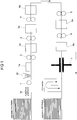
- the in the FIG. 1 schematically represented conventional production line comprises an IR dryer 10, a single-sided applicator 1, and five double application units 2, 3, 4, 5, 6 for simultaneous application of the respective resin layer on the top and bottom of the separated printed material plates, for example, from printed HDF plates and four each arranged in the processing direction behind the application units convection dryer 1 a, 2 a, 3 a, 4 a, 5 a, 6 a.
- the surface of the plates Prior to the first resin application, the surface of the plates is preheated by the IR dryer 10 to a temperature of about 45 ° C.
- the resin is applied via a rubberized roller in the commissioned work on the plate surface. The excess resin is pumped back into the order container, from where it is transported back to the rollers.
- a first scattering device 20 is provided for uniformly spreading the abrasion-resistant material, such as corundum on the first resin layer on top of the HDF plate.
- the abrasion-resistant material used is the corundum F200, which measures approximately 53-75 ⁇ m in diameter according to the FEPA standard.
- the scattering device 20 consists essentially of a storage hopper, a rotating, structured spiked roller and a scraper. It is determined by the rotational speed of the scattering roller, the order quantity of the material.
- the corundum falls at a distance of 5 cm on the treated with melamine resin plate. Since the first resin layer is still liquid at the time of scattering, the abrasion-resistant particles may sink into the resin layer.
- at least one hopper (not shown) for collecting excess abrasion-resistant particles (ie not scattered on the at least one wood-based panel, but rather before the retraction of the wood-based panel by means of the transport device under the scattering roller before derselbigen falling abrasion-resistant particles ) intended.
- the drying of the first resin layer is then carried out in the first convection dryer 1a at 150-250 ° C for 20-50 s.
- the third double applicator 3 for applying the third resin layer may be followed by a further diffuser 20 for applying glass beads to the third resin layer, followed by a third convection dryer 3a for drying the third resin layer.
- the diffuser 20 for the glass beads is optional.
- the glass beads can also be applied together with the third resin layer.
- the layer structure in a short-cycle press 7 After applying the fourth to sixth resin layer in a fourth to sixth Doppelsmokedswerk 4, 5, 6 and drying in each convection dryer 4a, 5a, 6a, the layer structure in a short-cycle press 7 at a pressing temperature of 180-220 ° C and a pressing time of 5 bis Cured for 25 seconds under a specific pressure of 35-55 kg / cm 2 . The pressed plates are cooled and stored.
- inventive production line of the IR dryer 10 is removed or turned off.
- the removal of the IR dryer from the production line avoids the otherwise static charging of the plate surface in the IR dryer, which allows the formation of a homogeneous scattered curtain of corundum.
- an additional double-sided applicator 1-1 installed in which the melamine-formaldehyde resin and corundum coated plate with melamine-formaldehyde resin (about 20 g / m 2 ) is coated.
- the unattached corundum is removed in small amounts and accumulates to saturation (about 10% by weight) in the melamine resin liquor.
- This lost portion of the corundum is now applied by the roller application of the commissioned work 1-1 continuously back to the plate.
- the corundum grains are covered with liquid resin or incorporated into the overlay layer. This prevents the removal of the corundum in the convection dryer due to the high air turbulence.
- the applicator 1-1 is followed by a convection dryer 1a followed by the other double application units 2, 3, 4, 5, 6 for simultaneous application of the respective resin layer on the top and bottom of the individual printed material plates and arranged in the processing direction behind the application aggregates convection dryers 2a, 3a, 4a, 5a, 6a.
Landscapes
- Life Sciences & Earth Sciences (AREA)
- Engineering & Computer Science (AREA)
- Wood Science & Technology (AREA)
- Application Of Or Painting With Fluid Materials (AREA)
- Laminated Bodies (AREA)
- Chemical And Physical Treatments For Wood And The Like (AREA)
- Dry Formation Of Fiberboard And The Like (AREA)
Abstract
Die vorliegende Erfindung betrifft ein Verfahren zur Herstellung einer abriebfesten Holzwerkstoffplatte mit einer Oberseite und einer Unterseite, wobei auf der Oberseite mindestens eine Dekorschicht, insbesondere als Druckdekor, vorgesehen ist, umfassend die Schritte: Auftragen von mindestens einer ersten Harzschicht (mittels Auftragswerk 1) auf die mindestens eine Dekorschicht auf der Oberseite der Holzwerkstoffplatte, gleichmäßiges Aufstreuen von abriebfesten Partikeln (mittels Streuvorrichtung 20) auf die erste Harzschicht auf der Oberseite der Holzwerkstoffplatte; wobei die mit den abriebfesten Partikeln versehene erste Harzschicht auf der Oberseite der Holzwerkstoffplatte nach dem Auftrag nicht getrocknet wird, und Auftragen von mindestens einer zweiten Harzschicht (mittels Auftragswerk 1-1) auf die mit den abriebfesten Partikeln versehene erste, feuchte Harzschicht auf der Oberseite der Holzwerkstoffplatte, anschließendes Trocknen des Aufbaus aus erster Harzschicht und zweiter Harzschicht auf der Oberseite der Holzwerkstoffplatte in mindestens einer Trocknungsvorrichtung (1a). Die vorliegende Erfindung betrifft ebenfalls eine Produktionslinie zur Durchführung dieses Verfahrens.The present invention relates to a method for producing an abrasion-resistant wood-based panel having a top side and a bottom side, wherein at least one decorative layer, in particular as a print decoration, is provided on the upper side, comprising the steps of applying at least one first resin layer (by means of a commissioned unit 1) to the at least one decorative layer on top of the wood-based panel, uniformly scattering abrasion-resistant particles (by means of spreading device 20) onto the first resin layer on top of the wood-based panel; wherein the first resin layer provided with the abrasion-resistant particles on top of the wood-based panel is not dried after the application, and applying at least a second resin layer (by means of applicator 1-1) to the first, moist resin layer provided on top of the abrasion-resistant particles Wood material board, then drying the structure of first resin layer and second resin layer on top of the wood-based panel in at least one drying device (1a). The present invention also relates to a production line for carrying out this method.
Description
Die vorliegende Erfindung betrifft ein Verfahren zur Herstellung einer abriebfesten mit einer Dekorschicht versehenen Holzwerkstoffplatte und eine Produktionslinie zur Durchführung dieses Verfahrens.The present invention relates to a method for producing an abrasion-resistant provided with a decorative layer wood-based panel and a production line for performing this method.
Eine Vielzahl von Produkten bzw. Produktoberflächen, die durch mechanische Beanspruchung einer Abnutzung ausgesetzt sind, müssen durch das Aufbringen von verschleißhemmenden Schichten, vor einer vorzeitigen Beschädigung oder Zerstörung durch Verschleiß geschützt werden. Bei diesen Produkten kann es sich z. B. um Möbeln, Innenausbauplatten, Fußböden usw. handeln. Je nach Beanspruchungsfrequenz und - stärke müssen dabei unterschiedliche Schutzmaßnahmen angewendet werden, damit dem Nutzer eine möglichst lange Nutzungsdauer garantiert werden kann.A variety of products or product surfaces which are subject to mechanical wear and tear must be protected by the application of wear-resistant coatings, from premature damage or destruction by wear. These products may, for. B. to furniture, interior panels, floors, etc. act. Depending on the frequency and intensity of the load, different protective measures have to be applied so that the user can be guaranteed the longest possible service life.
Eine Vielzahl der oben genannten Produkte besitzen dekorative Oberflächen, die bei Verschleiß aufgrund intensiver Nutzung schnell unansehnlich erscheinen und/oder sich nicht mehr reinigen lassen. Diese dekorativen Oberflächen bestehen sehr häufig aus mit duroplastischen Harzen imprägnierten Papieren, die in sogenannten Kurztaktpressen auf die verwendeten Holzwerkstoffträger aufgepresst werden. Als duroplastisches Harz kommt sehr häufig Melamin-Formaldehyd-Harz zum Einsatz.Many of the above products have decorative surfaces that quickly become unsightly when worn due to heavy use and / or are no longer cleanable. These decorative surfaces are very often made of impregnated with thermosetting resins papers that are pressed in so-called short-cycle presses on the wood material carrier used. As a thermosetting resin melamine-formaldehyde resin is very often used.
Ein Ansatz zur Verbesserung der Verschleißfestigkeit von dekorativen Oberflächen besteht im Auftrag bzw. Einbringen von abriebfesten Partikeln in die oberflächennahen Harzschichten. Dies kann z.B. durch den Auftrag eines abriebfeste Partikel enthaltenden Flüssigharzes auf die entsprechenden Oberflächen, wobei im Falle von dekorativen Holzwerkstoffplatten meist Korundpartikel als abriebfeste Partikel, verwendet werden. Bei dem Auftrag von korundhaltigem Melaminharz hat sich allerdings gezeigt, dass durch die Dichteunterschiede zwischen dem Melaminharz und dem Korund Probleme durch Sedimentation auftreten. Dies führt zu Ablagerungen in Ansatzbehältern, Pumpen, Rohrleitungen und den Walzenauftragsaggregaten. Deswegen muss zum einen der gesamte Bereich häufig durch Reinigen von den Ablagerungen befreit werden und zum anderen auch zur Erreichung eines bestimmten Verschleißwertes mit einem höheren Korundauftrag gearbeitet werden. Zusätzlich führt die angesprochene Sedimentation zu Inhomogenitäten in den Auftragswerken, was ebenfalls durch eine Höherdosierung kompensiert werden muss. Ein weiterer gravierender Nachteil dieser Technologie ist, dass durch die korundhaltigen Harzrezepturen ein erheblicher Verschleiß an allen Anlagenteilen auftritt, die mit der Harzrezeptur in Kontakt kommen. Die Höherdosierung in Kombination mit den Sedimentationsproblemen wiederum führt bei höheren Verschleißklassen zu einer schlechteren Transparenz. Dies macht sich besonders bei dunklen Dekoren negativ bemerkbar.One approach to improving the wear resistance of decorative surfaces is to apply abrasion-resistant particles to the near-surface resin layers. This can be done, for example, by the application of an abrasion-resistant particle-containing liquid resin to the corresponding surfaces, wherein in the case of decorative wood-based panels mostly corundum particles are used as abrasion-resistant particles. In the application of corundum melamine resin has been found, however, that occur due to the density differences between the melamine resin and the corundum problems due to sedimentation. This leads to deposits in neck tanks, pumps, pipelines and the roller application units. For this reason, on the one hand, the entire area often has to be freed from deposits by cleaning and, on the other hand, to achieve a certain level of wear, it is necessary to work with a higher amount of corundum. In addition, the mentioned sedimentation leads to inhomogeneities in the commissioned works, which also has to be compensated by a higher dosage. Another serious Disadvantage of this technology is that the corundum-containing resin formulations significant wear on all parts of the system that come into contact with the resin formulation. The higher dosage in combination with the sedimentation problems in turn leads to a lower transparency at higher wear classes. This is especially noticeable in dark decors.
Zur Vermeidung der Sedimentation der Korundpartikel im Flüssigharz und der damit verbundenen Probleme besteht ein anderer Ansatz zum Auftragen der abriebfesten Partikel darin, dass diese auf eine noch flüssige Harzschicht, die auf die Holzwerkstoffplatte aufgetragen wurde, mittels einer geeigneten Vorrichtung aufzustreuen. Hierbei zeigt sich, dass die Korundpartikel nicht sofort und vollständig in die Harzschicht eindringen, sondern teilweise lose aufeinander liegen. Die losen Korundpartikel können von nachfolgenden Luftströmungen, wie beispielsweise im Falle eines nachgelagerten Umlufttrockners, der die feuchte Melaminharzschicht trocknet, abgeblasen werden, wodurch dieses Korund der bestimmungsgemäßen Funktion (Abrieb) verloren geht und statt dessen für Verschleiß in nachgelagerten Anlagenteilen, wie beispielsweise dem Trockner führen.To avoid the sedimentation of the corundum particles in the liquid resin and the problems associated therewith, another approach for applying the abrasion-resistant particles is that they sprinkle on a still liquid resin layer which has been applied to the wood-based panel by means of a suitable device. This shows that the corundum particles do not penetrate immediately and completely into the resin layer, but partly lie loosely on one another. The loose corundum particles can be blown off by subsequent air currents, such as in the case of a downstream circulating air dryer, which dries the moist melamine resin layer, whereby this corundum of the intended function (abrasion) is lost and instead lead to wear in downstream equipment parts, such as the dryer ,
Für die Produktion ergeben sich somit verschiedene Nachteile. So wurde beobachtet, dass es aufgrund von elektrostatischer Aufladung der Korundpartikel die Ausbildung eines homogenen Streuvorhanges verhindert wird. Des Weiteren führt die Aufwirbelung im Konvektionstrockner zu einem Korundverlust und erfordert eine erhöhte Korundmenge; der Trockner wird durch den Korund verschmutzt; schneller Verschleiß der Transportketten im Trockner durch Korund; d.h. insgesamt erhöhte Materialkosten durch Korundverlust und Kettenverschleiß. Zudem bewirkt die starke Luftströmung im Trockner eine Verteilung des Feinkorunds in der Produktionshalle, was eine Gesundheitsgefährdung für die anwesenden Mitarbeiter darstellt. Auch kann es zu Produktionsausfall durch Verschmutzung der optischen Sensoren der Anlage durch Korundstaub kommen.There are thus various disadvantages for the production. It has been observed that due to electrostatic charging of the corundum particles, the formation of a homogeneous scattered curtain is prevented. Furthermore, the fluidization in the convection dryer leads to corundum loss and requires an increased amount of corundum; the dryer is contaminated by the corundum; rapid wear of transport chains in the dryer due to corundum; i.e. Overall increased material costs due to corundum loss and chain wear. In addition, the strong air flow in the dryer causes a distribution of Feinkorunds in the production hall, which is a health hazard for the staff present. It can also lead to production loss due to contamination of the optical sensors of the system by corundum dust.
Der vorliegenden Erfindung liegt daher die technische Aufgabe zugrunde, die oben angeführten Nachteile des bisherigen Ansatzes zum Aufstreuen von abriebfesten Partikel auf mit Flüssigharz beschichtete Holzwerkstoffplatten zu vermeiden und zu verbessern.The present invention is therefore based on the technical object to avoid the above-mentioned disadvantages of the previous approach to the scattering of abrasion-resistant particles on liquid resin-coated wood-based panels and improve.
Die gestellte Aufgabe wird erfindungsgemäß durch ein Verfahren mit den Merkmalen des Anspruchs 1 und eine Produktionslinie mit den Merkmalen des Anspruchs 11 gelöst.The stated object is achieved by a method with the features of claim 1 and a production line with the features of claim 11.
Demnach wird ein Verfahren zur Herstellung einer abriebfesten Holzwerkstoffplatte mit einer Oberseite und einer Unterseite, wobei auf der Oberseite mindestens eine Dekorschicht, insbesondere als Druckdekor, vorgesehen ist, bereitgestellt, welches die folgenden Schritte umfasst:
- Auftragen von mindestens einer ersten Harzschicht auf die mindestens eine Dekorschicht auf der Oberseite der Holzwerkstoffplatte,
- gleichmäßiges Aufstreuen von abriebfesten Partikeln auf die erste Harzschicht auf der Oberseite der Holzwerkstoffplatte;
- wobei die mit den abriebfesten Partikeln versehene erste Harzschicht auf der Oberseite der Holzwerkstoffplatte nach dem Auftrag nicht getrocknet wird, und
- Auftragen von mindestens einer zweiten Harzschicht auf die mit den abriebfesten Partikeln versehene erste, (noch) feuchte Harzschicht auf der Oberseite der Holzwerkstoffplatte,
- anschließendes Trocknen des Aufbaus aus erster Harzschicht und zweiter Harzschicht auf der Oberseite der Holzwerkstoffplatte in mindestens einer Trocknungsvorrichtung.
- Applying at least one first resin layer to the at least one decorative layer on top of the wood-based panel,
- uniform spreading of abrasion-resistant particles on the first resin layer on top of the wood-based panel;
- wherein the provided with the abrasion-resistant particles first resin layer on top of the wood-based panel after the order is not dried, and
- Applying at least one second resin layer to the first (still) moist resin layer provided with the abrasion-resistant particles on top of the wood-based panel,
- then drying the assembly of first resin layer and second resin layer on top of the wood-based panel in at least one drying device.
Das vorliegende Verfahren ermöglicht demnach die Bereitstellung von mit einer Dekorschicht versehenen Holzwerkstoffplatten in verschiedenen Formaten mit hoher Verschleißfestigkeit in einer kostengünstigen Weise. Gemäß dem vorliegenden Verfahren wird eine erste Harzschicht, insbesondere in Form einer ersten duroplastischen Harzschicht, wie einer Melamin-Formaldehyd-Harzschicht, auf die Dekorschicht (vorbehandelt oder nichtvorbehandelt) der Holzwerkstoffplatte aufgebracht. Es erfolgt zunächst kein Trocknen oder Antrocknen der ersten Harzschicht, sondern vielmehr werden die abriebfesten Partikel auf die nasse bzw. noch flüssige erste Harzschicht auf der Oberseite der Holzwerkstoffplatte gleichmäßig unter Verwendung einer geeigneten Streuvorrichtung aufgestreut. Da die erste Harzschicht zum Zeitpunkt des Aufstreuens noch flüssig vorliegt, können die abriebfesten Partikel in die Harzschicht einsinken. Anschließend (d.h. ohne Zwischentrocknung der ersten Harzschicht mit den darauf aufgestreuten abriebfesten Partikeln) wird auf die noch feuchte erste Harzschicht eine zweite Harzschicht aufgetragen. Dies erfolgt durch den Einbau eines zusätzlichen Auftragswerkes direkt hinter der Streumaschine (d.h. zwischen dem ersten Trockner und der Streumaschine). Das zusätzlich eingebaute Auftragswerk nimmt mit seinem Walzauftrag die nicht auf der ersten Harzschicht befestigten bzw. nicht in die erste Harzschicht eingedrungenen abriebfesten Partikel auf und transportiert es zurück in das Harzauftragswerk. Dort stellt sich eine Ausgleichskonzentration ein und die abgetragenen abriebfesten Partikel werden gleichmäßig über die Walze auf die nächsten Oberflächen aufgetragen. Es kommt somit zu einer Anreicherung der abriebfesten Partikel im zweiten Auftragswerk bis zu einem Gehalt von abriebfesten Partikeln von max. 10%. Neben einer Verhinderung des Wegblasens oder Aufnehmens von losen Partikeln, kann so auch die nachteilige Wirkung z.B. auf ein nachfolgendes Pressblech von aus der beschichteten Oberfläche herausragender Korundpartikel reduziert bzw. sogar weitgehend beseitigt werden.The present method thus makes it possible to provide wood-based panels provided with a decorative layer in various formats with high wear resistance in a cost-effective manner. According to the present method, a first resin layer, in particular in the form of a first thermosetting resin layer, such as a melamine-formaldehyde resin layer, is applied to the decorative layer (pretreated or not pretreated) of the wood-based panel. First, no drying or drying of the first resin layer takes place, but rather the abrasion-resistant particles are sprinkled evenly onto the wet or still liquid first resin layer on the upper side of the wood-based panel using a suitable scattering device. Since the first resin layer is still liquid at the time of scattering, the abrasion-resistant particles may sink into the resin layer. Subsequently (ie without intermediate drying of the first resin layer with the abrasion-resistant particles scattered thereon), a second resin layer is applied to the still moist first resin layer. This is done by installing an additional commissioning unit directly behind the spreader (ie between the first Dryer and the spreader). The additionally installed applicator unit takes with its rolling order the not fixed to the first resin layer or not penetrated into the first resin layer abrasion-resistant particles and transports it back into the resin applicator. There, a balance concentration sets in and the abraded abrasion-resistant particles are applied uniformly over the roller to the next surfaces. There is thus an accumulation of abrasion-resistant particles in the second commissioned work up to a content of abrasion-resistant particles of max. 10%. In addition to preventing the blowing away or picking up of loose particles, so can the adverse effect, for example, on a subsequent press plate reduced from the coated surface outstanding corundum particles or even largely eliminated.
Mit dem vorliegenden Verfahren ist eine Reduzierung des Verbrauchs an abriebfesten Material möglich, da kein Verlust der abriebfesten Partikel wie Korund im Trockner auftritt. Gleichzeitig wird eine Reduzierung der Staubbelastung der Umgebung und der offensichtlichen gesundheitlichen Belastung der Mitarbeiter; sowie Korundstaubablagerungen auf Anlagenteilen der Produktionslinie erreicht. Ein wesentlicher Vorteil ist auch die Reduzierung der Korundablagerung auf den Transportketten und somit Einsparung zusätzlicher Materialkosten durch Austausch der Ketten. Zudem werden die Standzeiten der Pressbleche beim nachgeschalteten Pressprozess zur Laminatbildung erhöht. Insgesamt werden die Verfahrenskosten aufgrund reduzierter Material- und Wartungskosten verringert. Auch müssen keine neuen Geräte / Vorrichtungen in die Produktionslinie eingebaut werden.With the present method, a reduction in the consumption of abrasion-resistant material is possible, since no loss of abrasion-resistant particles such as corundum occurs in the dryer. At the same time, there is a reduction in the dust pollution of the environment and the obvious health burden on employees; and corundum dust deposits on plant parts of the production line reached. Another major advantage is the reduction of corundum deposits on the transport chains and thus saving additional material costs by replacing the chains. In addition, the service life of the press plates are increased in the downstream pressing process for laminate formation. Overall, the process costs are reduced due to reduced material and maintenance costs. Also, no new devices / devices need to be built into the production line.
In einer bevorzugten Ausführungsform des vorliegenden Verfahrens wird die mit der Dekorschicht versehene Holzwerkstoffplatte vor dem Auftrag der ersten Harzschicht nicht in einem Trockner, wie z.B. einem IR Trockner, erwärmt. Dies kann durch Ausschalten eines in der Produktionslinie vorgesehenen IR-Trockners erfolgen oder es ist kein IR-Trockner in der Produktionslinie vorgesehen. Durch das Vermeiden der Erwärmung der mit einer Dekorschicht versehenen Holzwerkstoffplatte erfolgt keine elektrostatische Aufladung der Plattenoberfläche und der Streuvorhang bei Streuen des Korundes wird homogen.In a preferred embodiment of the present method, the wood-based panel provided with the decorative layer is not placed in a dryer, such as a dryer, prior to application of the first resin layer. an IR dryer, heated. This can be done by turning off an on-line IR dryer, or there is no IR dryer on the production line. By avoiding the heating of the wood-based panel provided with a decorative layer, there is no electrostatic charging of the panel surface and the scattering curtain becomes homogeneous when the corundum is scattered.
Der Verzicht des Erwärmens der bedruckten Holzwerkstoffplatte in einem IR-Trockner ist für einen Fachmann nicht naheliegend, da typischerweise auf die mittels Direktdruck aufgetragenen Dekorschichten eine Schutzschicht aus einem Harz aufgetragen wird. Die Schutzschicht kann ein Formaldehyd-haltiges Harz, insbesondere ein Melamin-Formaldehyd-Harz, Harnstoff-Formaldehyd-Harz oder Melamin-Harnstoff-Formaldehyd-Harz sein und Glaskugeln (Größe 50-150 µ) als Abstandshalter für die Zwischenlagerung der Platten enthalten. Diese Schutzschicht dient einem vorläufigen Schutz der Dekorschicht zur Lagerung vor der weiteren Veredelung. Die Schutzschicht auf der Dekorschicht ist noch nicht vollständig ausgehärtet, sondern mit einer gewissen Restfeuchte von ca. 10%, bevorzugt von ca. 6%, versehen und noch weiter vernetzbar. Derartige Schutzschichten sind z.B. in der
Der typischerweise zur Anwendung kommende Schritt des Erwärmens, von mit einer derartigen (duroplastischen) Schutzschicht versehenen Dekorschichten, dient einem Antrocknen der Schutzschicht und der Einstellung des Restfeuchtegrades und somit der Klebrigkeit der Schutzschicht und der Haftung von darauffolgenden Harzschichten.The typically used step of heating decorative layers provided with such a (thermosetting) protective layer serves to dry the protective layer and to adjust the residual moisture level and thus the tack of the protective layer and the adhesion of subsequent resin layers.
Im Falle des vorliegenden Verfahrens hat sich aber gezeigt, dass der Schritt des Erwärmens der Schutzschicht einen negativen Effekt auf das Streubild der abriebfesten Partikel hat. Ein Weglassen des Erwärmens der mit einer Schutzschicht versehenen bedruckten Holzwerkstoffplatte bewirkt eine Homogenisierung des Streubildes und somit eine gleichmäßige Verteilung der abriebfesten Partikel auf der Plattenoberfläche.In the case of the present method, however, it has been found that the step of heating the protective layer has a negative effect on the scattering pattern of the abrasion-resistant particles. Omitting the heating of the printed wood-based panel provided with a protective layer causes homogenization of the scattering pattern and thus a uniform distribution of the abrasion-resistant particles on the panel surface.
Die erste Harzschicht wird in einer Variante des Verfahrens in einer Menge zwischen 10-100 g/m2, bevorzugt 40-80 g/m2, insbesondere bevorzugt 45-60 g/m2 aufgetragen. Der Auftrag der ersten Harzschicht erfolgt z.B. mit einer rillierten Auftragswalze in einem ersten Auftragswerk. Die Schichtdicke der ersten, auf die Dekorschicht aufgetragenen Harzschicht beträgt 10 und 100 µm, bevorzugt zwischen 40 und 80 µm, insbesondere bevorzugt zwischen 45 und 60 µm.The first resin layer is applied in a variant of the method in an amount between 10-100 g / m 2 , preferably 40-80 g / m 2 , particularly preferably 45-60 g / m 2 . The application of the first resin layer is carried out, for example, with a grooved applicator roll in a first commissioned work. The layer thickness of the first resin layer applied to the decorative layer is 10 and 100 μm, preferably between 40 and 80 μm, particularly preferably between 45 and 60 μm.
In einer weiteren Ausführungsform des vorliegenden Verfahrens werden als abriebfeste Partikel Partikel aus Korund (Aluminiumoxide), Borcarbide, Siliziumdioxide, Siliziumcarbide verwendet. Besonders bevorzugt sind Korundpartikel. Dabei handelt es sich in bevorzugter Weise um Edelkorund weiß mit einer hohen Transparenz, damit die optische Wirkung des darunterliegenden Dekors so wenig wie möglich nachteilig beeinflusst wird. Korund weist eine ungleichmäßige Raumform auf.In a further embodiment of the present method, particles of corundum (aluminum oxides), boron carbides, silicon dioxides, silicon carbides are used as abrasion-resistant particles. Particularly preferred are corundum particles. These are preferably white corundum with a high transparency, so that the optical effect of the underlying decoration is adversely affected as little as possible. Corundum has a non-uniform spatial form.
Die Menge an aufgestreuten abriebfesten Partikeln beträgt 10 bis 50 g/m2, bevorzugt 10 bis 30 g/m2, insbesondere bevorzugt 15 bis 25 g/m2. Die Menge der aufgestreuten abriebfesten Partikel hängt von der zu erreichenden Abriebklasse ab. So liegt die Menge an abriebfesten Partikeln im Falle der Abriebklasse AC3 im Bereich zwischen 10 bis 15 g/m2, in der Abriebklasse AC4 zwischen 15 bis 20 g/m2 und in der Abriebklasse AC5 zwischen 20 bis 25 g/m2. Im vorliegenden Fall weisen die fertigen Platten bevorzugt die Abriebklasse AC4 auf.The amount of scattered abrasion-resistant particles is 10 to 50 g / m 2 , preferably 10 to 30 g / m 2 , particularly preferably 15 to 25 g / m 2 . The amount of scattered abrasion resistant particles depends on the abrasion class to be achieved. Thus, the amount of abrasion-resistant particles in the case of the abrasion class AC3 in the range between 10 to 15 g / m 2 , in the Abrasion class AC4 between 15 to 20 g / m 2 and in the abrasion class AC5 between 20 to 25 g / m 2 . In the present case, the finished plates preferably have the abrasion class AC4.
Es werden abriebfeste Partikel mit Körnungen in den Klassen F180 bis F240, bevorzugt F200 verwendet. Die Korngröße der Klasse F180 umfasst einen Bereich von 53 - 90 µm, F220 von 45-75 µm, F230 34-82 µm, F240 28-70 µm (FEPA Norm). In einer Variante werden als abriebfeste Partikel Edelkorund weiß F180 bis F240, bevorzugt in einem Hauptkornbereich von 53-90 µm verwendet. In einer besonders bevorzugten Ausführungsform werden Korundpartikel der Klasse F200 verwendet, wobei F200 eine Mischung zwischen F180 und F220 ist und einen Durchmesser zwischen 53 und 75 µm aufweist.Abrasion-resistant particles with grain sizes in classes F180 to F240, preferably F200, are used. The grain size class F180 covers a range of 53 - 90 μm, F220 of 45-75 μm, F230 34-82 μm, F240 28-70 μm (FEPA standard). In one variant, the high-grade corundum white F180 to F240 are used as abrasion-resistant particles, preferably in a main grain range of 53-90 μm. In a particularly preferred embodiment, corundum particles of class F200 are used, where F200 is a mixture between F180 and F220 and has a diameter between 53 and 75 μm.
Die abriebfesten Partikel dürfen nicht zu feinkörnig sein (Gefahr der Staubbildung), aber auch nicht zu grobkörnig. Die Größe der abriebfesten Partikel stellt somit ein Kompromiss dar. Insgesamt sollten die Korundpartikel jedoch größer sein als die gesamte Deckschicht, um Abriebfestigkeit zu bewirken.The abrasion-resistant particles must not be too fine-grained (risk of dust formation), but also not too coarse-grained. The size of the abrasion-resistant particles is thus a compromise. Overall, however, the corundum particles should be larger than the entire cover layer in order to achieve abrasion resistance.
In einer weitergehenden Ausführungsform können silanisierte Korundpartikel verwendet werden. Typische Silanisierungsmittel sind AminosilaneIn a further embodiment, silanized corundum particles can be used. Typical silanizing agents are aminosilanes
In einer weitergehenden Variante des vorliegenden Verfahrens kann das als erste Harzschicht auf die Oberseite der Holzwerkstoffplatte aufzutragende Harz Fasern, insbesondere Holzfasern oder Zellulosefasern, enthalten. Die Auftragsmenge der Fasern, wie z.B. Zellulosefasern, beträgt, wenn diese zusammen mit der ersten Harzschicht aufgebracht werden, zwischen 0,1-0,5 g/m2, bevorzugt 0,2-0,4 g/m2, insbesondere bevorzugt 0,25 g/m2. Die Zugabe von Fasern wie Zellulosefasern zu der ersten Schicht trägt zur Erhöhung der Viskosität der Harzflotte und somit zu erhöhtem Auftrag der ersten Deckschicht auf die Holzwerkstoffplatte bei.In a further variant of the present method, the resin to be applied as the first resin layer to the upper side of the wood-based panel may contain fibers, in particular wood fibers or cellulose fibers. The amount of application of the fibers, such as cellulose fibers, when applied together with the first resin layer, is between 0.1-0.5 g / m 2 , preferably 0.2-0.4 g / m 2 , particularly preferably 0 , 25 g / m 2 . The addition of fibers such as cellulose fibers to the first layer contributes to increasing the viscosity of the resin liquor and thus to increased application of the first cover layer on the wood-based panel.
In einer weiteren Ausführungsform des vorliegenden Verfahrens wird die zweite auf die Oberseite der Holzwerkstoffplatte aufzutragende Harzschicht in einer Menge zwischen 10-50 g/m2, bevorzugt 20-30 g/m2, insbesondere bevorzugt 20-25 g/m2 aufgetragen. Insgesamt ist die Menge der zweiten Harzschicht geringer als die Menge der ersten Harzschicht.In a further embodiment of the present method, the second resin layer to be applied to the upper side of the wood-based panel is applied in an amount between 10-50 g / m 2 , preferably 20-30 g / m 2 , particularly preferably 20-25 g / m 2 . Overall, the amount of the second resin layer is less than the amount of the first resin layer.
Die Gesamtmenge an erster und zweiter Harzschicht liegt zwischen 50-100 g/m2, bevorzugt 60-80 g/m2, insbesondere bevorzugt bei 70 g/m2. So beträgt in einer Variante die Menge der ersten Harzschicht 50 g/m2 und die Menge des zweiten Harzschicht 25 g/m2.The total amount of the first and second resin layers is between 50-100 g / m 2 , preferably 60-80 g / m 2 , particularly preferably 70 g / m 2 . Thus, in one variant, the amount of the first resin layer is 50 g / m 2 and the amount of the second resin layer is 25 g / m 2 .
Wie bereits oben erwähnt, kommt es zu einer Anreicherung der abriebfesten Partikel in der zweiten Harzschicht durch Mitnahme von losen Partikeln durch das zweite Auftragswerk. So kann sich in dem als zweite Harzschicht aufzutragenden Harz ein Gehalt an abriebfesten Partikel von 5 bis 15 Gew%, bevorzugt 10 Gew% einstellen.As already mentioned above, an accumulation of the abrasion-resistant particles in the second resin layer occurs by entrainment of loose particles through the second applicator. Thus, in the resin to be applied as the second resin layer, a content of abrasion-resistant particles of 5 to 15% by weight, preferably 10% by weight, can be established.
In einer weiteren Ausführungsform ist die mindestens eine Holzwerkstoffplatte eine mitteldichte Faser (MDF)-, hochdichte Faser (HDF)- oder Grobspan (OSB)- oder Sperrholzplatte und/oder eine Holz-Kunststoff-Platte.In a further embodiment, the at least one wood-based panel is a medium-density fiber (MDF), high-density fiber (HDF) or coarse chip (OSB) or plywood board and / or a wood-plastic board.
In einer Ausführungsform wird parallel zur zweiten Harzschicht auf der Oberseite der Holzwerkstoffplatte auch eine Harzschicht auf die Unterseite der Holzwerkstoffplatte aufgetragen. Die Menge der auf die Unterseite der Holzwerkstoffplatte aufgetragenen Harzschicht kann zwischen 50-100 g/m2, bevorzugt 60-80 g/m2, insbesondere bevorzugt 60 g/m2 betragen. Bevorzugt ist die untere Harzschicht (z.B. bräunlich) eingefärbt, um einen Gegenzug zu simulieren.In one embodiment, a resin layer is applied to the underside of the wood-based panel parallel to the second resin layer on top of the wood-based panel. The amount of the resin layer applied to the underside of the wood-based panel may be between 50-100 g / m 2 , preferably 60-80 g / m 2 , particularly preferably 60 g / m 2 . Preferably, the lower resin layer (eg brownish) is colored to simulate a return.
Der Feststoffgehalt des für die Oberseite und die Unterseite verwendeten Harzes liegt sowohl für die Oberseite als auch die Unterseite bei 50-70 Gew%, bevorzugt 50-60 Gew%, insbesondere bevorzugt 55 Gew%.The solid content of the resin used for the top and the bottom is 50-70% by weight, preferably 50-60% by weight, more preferably 55% by weight for both the top and the bottom.
Die zweite Harzschicht wird bevorzugt parallel bzw. gleichzeitig auf die Oberseite und Unterseite der Holzwerkstoffplatte in mindestens einer Doppelauftragsvorrichtung (Walzenauftragsaggregat) aufgetragen. Nach Auftrag der zweiten Harzschicht erfolgt eine Trocknung (Lufttrocknung) des Aufbaus aus erster und zweiter Harzschicht in einer ersten Trocknungsvorrichtung. Demnach wird mindestens eine Harzschicht auf die Unterseite der Holzwerkstoffplatte zusammen mit der auf die Oberseite der Holzwerkstoffplatte aufzutragenden zweiten Harzschicht aufgetragen.The second resin layer is preferably applied parallel or simultaneously to the top and bottom of the wood-based panel in at least one double application device (roller application unit). After application of the second resin layer, drying (air drying) of the construction of first and second resin layers takes place in a first drying device. Accordingly, at least one resin layer is applied to the underside of the wood-based panel together with the second resin layer to be applied to the top of the wood-based panel.
Die auf der Unterseite aufgetragene(n) Harzschicht(en) wirken als Gegenzug. Durch das Aufbringen der Harzschichten auf die Oberseite und Unterseite der Holzwerkstoffplatten in ungefähr den gleichen Mengen wird gewährleistet, dass die durch die aufgebrachten Schichten beim Verpressen entstehenden Zugkräfte auf die Holzwerkstoffplatte sich gegenseitig aufheben. Der auf die Unterseite aufgebrachte Gegenzug entspricht im Schichtaufbau und der jeweiligen Schichtdicke ungefähr der auf der Oberseite aufgebrachten Schichtfolge mit dem Unterschied der abriebfesten Partikel und Glaskugeln wie im Folgenden im Detail erläutert wird.The resin layer (s) applied on the underside act as a countermove. By applying the resin layers on the top and bottom of the wood-based panels in approximately the same amounts ensures that the resulting by the applied layers during compression tensile forces on the wood-based panel cancel each other. The applied on the underside counter-train corresponds in the layer structure and the respective layer thickness about the applied on the top Layer sequence with the difference of the abrasion-resistant particles and glass beads as will be explained in detail below.
In einer weiteren Ausführungsform des vorliegenden Verfahrens wird mindestens eine weitere Harzschicht, bevorzugt eine dritte, vierte, fünfte, sechste und siebente Harzschicht, auf den getrockneten Aufbau aus mit den abriebfesten Partikeln versehener erster und zweiter Harzschicht auf der Oberseite der Holzwerkstoffplatte aufgetragen und jeweils nach dem Auftrag getrocknet wird.In a further embodiment of the present method, at least one further resin layer, preferably a third, fourth, fifth, sixth and seventh resin layer, is applied to the dried structure of first and second resin layers provided with the abrasion-resistant particles on top of the wood-based panel and respectively after Order is dried.
Es ist weiterhin bevorzugt, dass die weiteren Harzschichten Glaskugeln und/oder Fasern, insbesondere Holzfasern oder Zellulosefasern, umfassen.It is further preferred that the further resin layers comprise glass beads and / or fibers, in particular wood fibers or cellulose fibers.
So kann eine dritte Harzschicht parallel auf die Oberseite und Unterseite der Holzwerkstoffplatte aufgetragen werden, d.h. auf den jeweilig getrockneten Harzaufbau. Im Falle der Oberseite wäre dies der Harzaufbau aus erster und zweiter Harzschicht inklusive der abriebfesten Partikel und im Falle der Unterseite wäre dies eine Harzschicht.Thus, a third resin layer may be applied in parallel to the top and bottom of the wood-based panel, i. on the respective dried resin structure. In the case of the top, this would be the resin structure of first and second resin layers including the abrasion-resistant particles, and in the case of the bottom, this would be a resin layer.
Die Menge der auf die Oberseite der Holzwerkstoffplatte aufgetragenen dritten Harzschicht kann zwischen 10-50 g/m2, bevorzugt 20-30 g/m2, insbesondere bevorzugt 25 g/m2 betragen.The amount of the third resin layer applied to the upper side of the wood-based panel may be between 10-50 g / m 2 , preferably 20-30 g / m 2 , particularly preferably 25 g / m 2 .
Die Menge der auf die Unterseite der Holzwerkstoffplatte parallel aufgetragenen Harzschicht kann zwischen 30-80 g/m2, bevorzugt 40-60 g/m2, insbesondere bevorzugt bei 50 g/m2 liegen.The amount of the resin layer applied in parallel to the underside of the wood-based panel may be between 30-80 g / m 2 , preferably 40-60 g / m 2 , particularly preferably 50 g / m 2 .
Der Feststoffgehalt des für die dritte Harzschicht verwendeten Harzes liegt sowohl für die Oberseite als auch die Unterseite bei 50-70 Gew%, bevorzugt 50-60 Gew%, insbesondere bevorzugt 55 Gew%.The solid content of the resin used for the third resin layer is 50-70% by weight, preferably 50-60% by weight, more preferably 55% by weight for both the top and the bottom.
In einer weiteren Ausführungsform des vorliegenden Verfahrens wird jeweils mindestens eine vierte Harzschicht auf die Oberseite und parallel auf die Unterseite der Holzwerkstoffplatte aufgetragen.In a further embodiment of the present method, in each case at least one fourth resin layer is applied to the upper side and parallel to the underside of the wood-based panel.
Die Menge der auf die Oberseite der Holzwerkstoffplatte aufgetragenen vierten Harzschicht kann zwischen 10-40 g/m2, bevorzugt 15-30 g/m2, insbesondere bevorzugt 20 g/m2 betragen, wobei der Feststoffgehalt zwischen 50-80 Gew%, bevorzugt 60-70 Gew%, insbesondere bevorzugt 60-65 Gew%, z.B. bei 61,5 Gew% liegt.The amount of the fourth resin layer applied to the upper side of the wood-based panel may be between 10-40 g / m 2 , preferably 15-30 g / m 2 , particularly preferably 20 g / m 2 , the solids content being between 50-80% by weight, preferably 60-70% by weight, particularly preferably 60-65% by weight, for example at 61.5% by weight.
In einer Variante kann das als vierte Harzschicht auf die Oberseite der Holzwerkstoffplatte aufzutragende Harz Glaskugeln enthalten, wobei die Glaskugeln bevorzugt als Abstandshalter fungieren. Die bevorzugt verwendeten Glaskugeln weisen einen Durchmesser von 50-100 µm, bevorzugt von 60-80 µm auf. Die Auftragsmenge der Glaskugeln, wenn diese zusammen mit der dritten Harzschicht aufgebracht werden, beträgt 1-5 g/m2, bevorzugt 2-4 g/m2, insbesondere bevorzugt 3 g/m2.In a variant, the resin to be applied as the fourth resin layer to the upper side of the wood-based panel may comprise glass spheres, the glass spheres preferably acting as spacers. The glass beads preferably used have a diameter of 50-100 microns, preferably from 60-80 microns. The application amount of the glass beads, when applied together with the third resin layer, is 1-5 g / m 2 , preferably 2-4 g / m 2 , particularly preferably 3 g / m 2 .
In einer weiteren Variante können die Glaskugeln auf die auf der Oberseite der Holzwerkstoffplatte aufgetragene vierte Harzschicht aufgestreut werden. In diesem Fall, d.h. wenn die Glaskugeln aufgestreut werden, beträgt die Auftragsmenge der Glaskugeln 5-10 g/m2, bevorzugt 6-8 g/m2, insbesondere bevorzugt 6 g/m2.In a further variant, the glass spheres can be sprinkled onto the fourth resin layer applied to the upper side of the wood-based panel. In this case, ie, when the glass beads are scattered, the application amount of the glass beads is 5-10 g / m 2 , preferably 6-8 g / m 2 , particularly preferably 6 g / m 2 .
Die Menge der auf die Unterseite der Holzwerkstoffplatte parallel aufgetragenen Harzschicht kann zwischen 20-70 g/m2, bevorzugt 30-50 g/m2, insbesondere bevorzugt 40 g/m2 bei einem Feststoffgehalt von 50-70 Gew%, bevorzugt 50-60 Gew%, insbesondere bevorzugt 55 Gew% betragen.The amount of the resin layer applied in parallel to the underside of the wood-based panel can be between 20-70 g / m 2 , preferably 30-50 g / m 2 , particularly preferably 40 g / m 2 at a solids content of 50-70% by weight, preferably 50-70% by weight. 60% by weight, particularly preferably 55% by weight.
Es ist ebenfalls von Vorteil, wenn die jeweils auf der Oberseite und Unterseite der Holzwerkstoffplatte aufgetragene Harzschicht in mindestens einer Trocknungsvorrichtung getrocknet wird.It is likewise advantageous if the resin layer applied in each case on the upper side and lower side of the wood-based panel is dried in at least one drying device.
Im Anschluss an den Trocknungsprozess für die vierte obere Harzschicht und parallele untere Harzschicht ist es optional möglich, jeweils mindestens eine fünfte Harzschicht auf die Oberseite und die Unterseite der Holzwerkstoffplatte aufzutragen.Following the drying process for the fourth upper resin layer and parallel lower resin layer, it is optionally possible to apply at least one fifth resin layer to the upper side and the lower side of the wood-based panel.
Die Menge der auf die Oberseite der Holzwerkstoffplatte aufgetragenen fünften Harzschicht kann zwischen 10-40 g/m2, bevorzugt 15-30 g/m2, insbesondere bevorzugt 20 g/m2 bei einem Feststoffgehalt von 50-80 Gew%, bevorzugt 60-70 Gew%, insbesondere bevorzugt 60-65 Gew%, z.B. 61,6 Gew% betragen.The amount of the fifth resin layer applied to the upper side of the wood-based panel may be between 10-40 g / m 2 , preferably 15-30 g / m 2 , particularly preferably 20 g / m 2 at a solids content of 50-80% by weight, preferably 60-80% by weight. 70% by weight, particularly preferably 60-65% by weight, for example 61.6% by weight.
In einer weitergehenden Variante des vorliegenden Verfahrens kann das als fünfte Harzschicht auf die Oberseite der Holzwerkstoffplatte aufzutragende Harz Glaskugeln, , enthalten. Im Falle der Zugabe von Glaskugeln zum aufzutragenden Harz beträgt die Auftragsmenge an Glaskugeln 1-5 g/m2, bevorzugt 2-4 g/m2, insbesondere bevorzugt 3 g/m2.
Die Menge der auf die Unterseite der Holzwerkstoffplatte parallel aufgetragenen Harzschicht kann zwischen 10-60 g/m2, bevorzugt 20-50 g/m2, insbesondere bevorzugt 30 g/m2 bei einem Feststoffgehalt von 50-70 Gew%, bevorzugt 50-60 Gew%, insbesondere bevorzugt 55 Gew% liegen.In a further variant of the present method, the resin to be applied as the fifth resin layer on top of the wood-based panel may contain glass beads. In the case of adding glass beads to the resin to be applied, the application amount of glass beads is 1-5 g / m 2 , preferably 2-4 g / m 2 , particularly preferably 3 g / m 2 .
The amount of the resin layer applied in parallel to the underside of the wood-based panel may be between 10-60 g / m 2 , preferably 20-50 g / m 2 , particularly preferably 30 g / m 2 in a Solids content of 50-70% by weight, preferably 50-60% by weight, particularly preferably 55% by weight.
In einer noch weitergehenden Variante des vorliegenden Verfahrens werden eine sechste und eine siebente Harzschicht auf die Oberseite und jeweils die dazu komplementären Harzschichten auf die Unterseite der Holzwerkstoffplatte aufgetragen. Auch die auf die Oberseite aufgetragene sechste und siebente Harzschicht können jeweils Fasern oder Glaskugeln enthalten.In a still further variant of the present method, a sixth and a seventh resin layer are applied to the top and each of the complementary resin layers on the underside of the wood-based panel. Also, the sixth and seventh resin layers coated on top may each contain fibers or glass beads.
Es ist noch anzumerken, dass zu sämtlichen Harzschichten jeweils Additive, wie Härter, Netzmittel, Entschäumer, Trennmittel und/oder weitere Komponenten zugegeben werden können.It should also be noted that additives such as hardeners, wetting agents, antifoams, release agents and / or further components can be added to all resin layers.
Die jeweils auf der Oberseite und Unterseite der Holzwerkstoffplatte aufgetragene sechste und siebente Harzschicht (als abschließende Schichten) werden jeweils in mindestens einer weiteren dem jeweiligen Auftragswerk zugeordneten Trocknungsvorrichtung getrocknet. Das Trocknen der jeweiligen Harzschichten erfolgt bevorzugt auf eine Restfeuchte von 6-9 Gew% z.B. in einem Umlufttrockner.The sixth and seventh resin layers (as final layers) which are respectively applied to the upper side and underside of the wood-based panel are respectively dried in at least one further drying device assigned to the respective applicator. The drying of the respective resin layers is preferably carried out to a residual moisture of 6-9 wt%, e.g. in a circulating air dryer.
In dem sich an den letzten Trocknungsschritt anschließenden Pressschritt erfolgt ein Verpressen des Schichtaufbaus unter Druck- und Temperatureinfluss in einer Kurztaktpresse bei Temperaturen zwischen 150 und 250°C, bevorzugt zwischen 180 und 230°C, insbesondere bevorzugt bei 200°C und einem Druck zwischen 100 und 1000 N/cm2, bevorzugt 300 und 700 N/cm2, insbesondere bevorzugt zwischen 400 und 600 N/cm2.In the pressing step following the last drying step, the layer structure is compressed under pressure and temperature in a short-cycle press at temperatures between 150 and 250 ° C., preferably between 180 and 230 ° C., particularly preferably at 200 ° C. and a pressure between 100 and 1000 N / cm 2 , preferably 300 and 700 N / cm 2 , particularly preferably between 400 and 600 N / cm 2 .
Die bereits oben erwähnte Dekorschicht kann mittels Direktdruck aufgetragen werden. Im Falle eines Direktdruckes erfolgt der Auftrag einer wasserbasierten, pigmentierten Druckfarbe im Tiefdruck- oder im Digitaldruckverfahren, wobei die wasserbasierte pigmentierte Druckfarbe in mehr als einer Schicht auftragbar ist, z.B. in Form von zwei bis zehn Schichten, bevorzugt drei bis acht Schichten.The above-mentioned decorative layer can be applied by direct printing. In the case of direct printing, the application of a water-based, pigmented ink by gravure or digital printing, wherein the water-based pigmented ink is applied in more than one layer, e.g. in the form of two to ten layers, preferably three to eight layers.
Im Falle des Direktdrucks erfolgt der Auftrag der mindestens einen Dekorschicht wie erwähnt mittels eines analogen Tiefdruck- und/oder eines Digitaldruckverfahrens. Das Tiefdruckverfahren ist eine Drucktechnik, bei der die abzubildenden Elemente als Vertiefungen einer Druckform vorliegen, die vor dem Druck eingefärbt wird. Die Druckfarbe befindet sich vornehmlich in den Vertiefungen und wird aufgrund des Anpressdruckes der Druckform und von Adhäsionskräften auf den zu bedruckenden Gegenstand, wie z.B. eine Holzfaserträgerplatte, übertragen. Hingegen wird beim Digitaldruck das Druckbild direkt von einem Computer in eine Druckmaschine, wie z.B. einen Laserdrucker oder Tintenstrahldrucker übertragen. Dabei entfällt die Verwendung einer statischen Druckform. In beiden Verfahren ist die Verwendung von wässrigen Farben und Tinten oder farbgebender Mittel auf UV-Basis möglich. Ebenfalls ist es vorstellbar, die genannten Drucktechniken aus Tief- und Digitaldruck zu kombinieren. Eine geeignete Kombination der Drucktechniken kann zum einen unmittelbar auf der Trägerplatte bzw. der zu bedruckenden Schicht erfolgen oder auch vor dem Drucken durch Anpassung der verwendeten elektronischen Datensätze.In the case of direct printing, the application of the at least one decorative layer takes place as mentioned by means of an analogue gravure printing and / or a digital printing process. The gravure printing process is a printing technique in which the elements to be imaged are present as depressions of a printing form, which is inked before printing. The ink is located primarily in the wells and is due to the contact pressure of the printing plate and of adhesion forces on the object to be printed, such as a wood fiber support plate transferred. On the other hand, in digital printing, the print image is transferred directly from a computer to a printing machine, such as a laser printer or inkjet printer. This eliminates the use of a static printing form. Both methods allow the use of aqueous inks and inks or UV-based colorants. It is also conceivable to combine the mentioned printing techniques from gravure and digital printing. A suitable combination of the printing techniques can be done either directly on the support plate or the layer to be printed or even before printing by adjusting the electronic records used.
Es ist ebenfalls möglich, dass zwischen der Holzwerkstoffplatte bzw. Trägerplatte und der mindestens eine Dekorschicht mindestens eine Grundierungsschicht angeordnet ist.It is also possible that at least one primer layer is arranged between the wood-based material board or support plate and the at least one decorative layer.
Die dabei bevorzugt verwendete Grundierungsschicht umfasst eine Zusammensetzung aus Kasein als Bindemittel und anorganische Pigmente, insbesondere anorganische Farbpigmente. Als Farbpigmente können in der Grundierungsschicht weiße Pigmente wie Titandioxid verwendet werden oder aber auch weitere Farbpigmente, wie Calciumcarbonat, Bariumsulfat oder Bariumcarbonat. Die Grundierung kann neben den Farbpigmenten und dem Kasein noch Wasser als Lösemittel enthalten. Es ist ebenfalls bevorzugt, wenn die aufgetragene pigmentierte Grundschicht aus mindestens einer, bevorzugt aus mindestens zwei, insbesondere bevorzugt aus mindestens vier nacheinander aufgetragenen Lagen bzw. Aufträgen besteht, wobei die Auftragsmenge zwischen den Lagen bzw. Aufträgen gleich oder verschieden sein kann.The primer layer preferably used here comprises a composition of casein as binder and inorganic pigments, in particular inorganic color pigments. As color pigments, white pigments such as titanium dioxide can be used in the primer layer, or else further color pigments, such as calcium carbonate, barium sulfate or barium carbonate. The primer may contain water as a solvent in addition to the color pigments and casein. It is likewise preferred if the applied pigmented basecoat comprises at least one, preferably at least two, more preferably at least four, successively applied layers or jobs, the application quantity between the layers or applications being the same or different.
Das vorliegende Verfahren ermöglicht somit die Herstellung einer abriebfesten mit einer Dekorschicht versehenen Holzwerkstoffplatte mit einem Harzaufbau mit abriebfesten Partikeln. Die mit einer Dekorschicht versehene Holzwerkstoffplatte umfasst einen Harzaufbau aus erster und zweiter jeweils abriebfeste Partikel enthaltenden Harzschicht auf der Oberseite, einer dazu korrespondierenden Harzschicht auf der Unterseite, mindestens einer dritten Harzschicht auf der Oberseite und einer dazu korrespondierenden Harzschicht auf Unterseite der Holzwerkstoffplatte, mindestens einer vierten, fünften, sechsten und siebenten Harzschicht auf der Oberseite und jeweils dazu korrespondierenden Harzschichten auf der Unterseite der Holzwerkstoffplatte, wobei in der auf der Oberseite der Holzwerkstoffplatte vorgesehenen vierten bis siebten Harzschicht jeweils Glaskugeln enthalten sein können.The present method thus enables the production of an abrasion-resistant provided with a decorative layer wood-based panel having a resin structure with abrasion-resistant particles. The provided with a decorative layer wood-based panel comprises a resin composition of first and second respective abrasion resistant particles containing resin layer on the top, a corresponding thereto resin layer on the bottom, at least a third resin layer on the top and a corresponding resin layer on the underside of the wood-based panel, at least a fourth , Fifth, sixth and seventh resin layer on the top and respectively corresponding resin layers on the underside of the wood-based panel, wherein in the provided on the upper side of the wood-based panel fourth to seventh resin layer may each contain glass beads.
In einer bevorzugten Ausführungsform ermöglicht das vorliegende Verfahren die Herstellung einer abriebfesten Holzwerkstoffplatte mit folgendem Schichtaufbau (von unten nach oben gesehen): Gegenzug aus sechs Harzschichten - Holzwerkstoffplatte - Grundierungsschicht - Druckdekorschicht - erste Harzschicht mit Zellulosefasern - Schicht aus abriebfesten Partikeln - zweite Harzschicht - dritte Harzschicht - vierte Harzschicht mit Glaskugeln - fünfte Harzschicht mit Glaskugeln - sechste Harzschicht mit Glaskugeln - siebente Harzschicht mit Glaskugeln.In a preferred embodiment, the present method makes it possible to produce an abrasion-resistant wood-based panel with the following layer structure (viewed from below): backing of six resin layers - wood-based panel - primer layer - print decor layer - first resin layer with cellulose fibers - layer of abrasion-resistant particles - second resin layer - third resin layer - fourth resin layer with glass spheres - fifth resin layer with glass spheres - sixth resin layer with glass spheres - seventh resin layer with glass spheres.
Die Produktionslinie zur Durchführung des vorliegenden Verfahrens umfasst folgende Elemente:
- mindestens eine erste Auftragsvorrichtung zum Auftragen einer ersten Harzschicht auf die Oberseite der Holzwerkstoffplatte,
- mindestens eine in Verarbeitungsrichtung hinter der ersten Auftragsvorrichtung angeordnete Vorrichtung zum Aufstreuen einer vorbestimmten Menge an abriebfesten Partikeln;
- mindestens eine in Verarbeitungsrichtung hinter der ersten Auftragsvorrichtung und Streuvorrichtung angeordnete zweite Auftragsvorrichtung zum Auftragen einer zweiten Harzschicht auf die Oberseite der Holzwerkstoffplatte,
- mindestens eine in Verarbeitungsrichtung hinter der zweiten Auftragsvorrichtung angeordnete erste Trocknungsvorrichtung zum Trocknen des Schichtaufbaus aus erster und zweiter Harzschicht.
- at least one first application device for applying a first resin layer to the upper side of the wood-based panel,
- at least one downstream of the first applicator device arranged in the processing direction for spreading a predetermined amount of abrasion-resistant particles;
- at least one second application device arranged behind the first application device and scattering device in the processing direction for applying a second resin layer to the upper side of the wood-based material board,
- at least one in the processing direction behind the second applicator arranged first drying device for drying the layer structure of first and second resin layer.
In einer bevorzugten Variante der vorliegenden Produktionslinie ist vor der ersten Auftragsvorrichtung keine Trocknungsvorrichtung vorgesehen ist oder für den Fall, dass eine Trocknungsvorrichtung als Teil der Produktionslinie installiert ist, ist diese Trocknungsvorrichtung nicht in Betrieb, d.h. nicht aktiv.In a preferred variant of the present production line, no drying device is provided in front of the first application device, or in the case where a drying device is installed as part of the production line, this drying device is not in operation, i. not active.
Auch ist zwischen der Streuvorrichtung und der zweiten Auftragsvorrichtung keine Trocknungsvorrichtung vorgesehen. Vielmehr wird die noch feuchte Platte nach Verlassen der Streuvorrichtung unmittelbar in die zweite Auftragsvorrichtung eingeführt.Also, no drying device is provided between the scattering device and the second application device. Rather, the still moist plate is introduced immediately after leaving the spreader in the second application device.
In einer Variante der Produktionslinie ist die zweite Auftragsvorrichtung zum Auftragen der zweiten Harzschicht als Doppelauftragswerk ausgebildet ist, so dass gleichzeitig bzw. parallel mit der zweiten Harzschicht auf der Oberseite eine korrespondierende Harzschicht auf die Unterseite der Holzwerkstoffplatte aufgetragen wird.In a variant of the production line, the second application device for applying the second resin layer is designed as a double applicator, so that simultaneously or in parallel with the second resin layer on top, a corresponding resin layer is applied to the underside of the wood-based panel.
In einer weitergehenden Variante umfasst die Produktionslinie mindestens eine in Verarbeitungsrichtung hinter der ersten Trocknungsvorrichtung angeordnete weitere Auftragsvorrichtungen zum Auftragen von weiteren Harzschichten auf die Oberseite und/oder Unterseite der Trägerplatte und anschließende Trocknungsvorrichtungen zum Trocknen der weiteren oberen und/oder unteren Harzschichten.In a further variant, the production line comprises at least one further application device arranged behind the first drying device in the processing direction for applying further resin layers to the top and / or bottom of the carrier plate and subsequent drying devices for drying the further top and / or bottom resin layers.
In einer Ausführungsform umfasst die vorliegende Produktionslinie insgesamt ein einfaches, einseitiges Auftragswerk zum Auftragen der ersten Harzschicht auf die Oberseite der bedruckten Holzwerkstoffplatte und sechs Doppelauftragswerke zum Auftragen von sechs weiteren Harzschichten auf die Oberseite und Unterseite der Holzwerkstoffplatte, wobei hinter jedem Doppelauftragswerk mindestens eine Trocknungsvorrichtung zum Trocknen der oberen und/oder unteren Harzschicht vorgesehen ist.In one embodiment, the present production line comprises a total of a simple, single-sided applicator for applying the first layer of resin to the top of the printed wood board and six double applicators for applying six further layers of resin to the top and bottom of the board, with at least one drying device behind each double applicator for drying the upper and / or lower resin layer is provided.
Die Produktionslinie umfasst ebenfalls bevorzugt eine in Verarbeitungsrichtung hinter der letzten Trocknungsvorrichtung angeordnete Kurztaktpresse (KT-Presse).The production line likewise preferably comprises a short-cycle press (KT press) arranged in the processing direction behind the last drying device.
In einer bevorzugten Ausführungsform umfasst die Produktionslinie zur Durchführung des vorliegenden Verfahrens folgende Elemente:
- mindestens eine erste Auftragsvorrichtung zum Auftragen einer ersten Harzschicht, die ggf. Fasern enthalten kann, auf die Oberseite der Holzwerkstoffplatte;
- mindestens eine in Verarbeitungsrichtung hinter der ersten Auftragsvorrichtung angeordnete Vorrichtung zum Aufstreuen einer vorbestimmten Menge an abriebfesten Partikeln;
- mindestens eine in Verarbeitungsrichtung hinter der ersten Auftragsvorrichtung und Streuvorrichtung angeordnete zweite Auftragsvorrichtung zum Auftragen einer zweiten Harzschicht auf die Oberseite der Holzwerkstoffplatte,
- mindestens eine in Verarbeitungsrichtung hinter der zweiten Auftragsvorrichtung angeordnete erste Trocknungsvorrichtung zum Trocknen des Schichtaufbaus aus erster und zweiter Harzschicht;
- mindestens eine in Verarbeitungsrichtung hinter der ersten Trocknungsvorrichtung angeordnete dritte Auftragsvorrichtung zum Auftragen einer dritten Harzschicht auf die Oberseite und/oder einer Harzschicht parallel auf die Unterseite der Trägerplatte,
- mindestens eine in Verarbeitungsrichtung hinter der dritten Auftragsvorrichtung angeordnete weitere Trocknungsvorrichtung zum Trocknen der dritten oberen und/oder korrespondierenden unteren Harzschicht;
- mindestens eine in Verarbeitungsrichtung hinter der weiteren Trocknungsvorrichtung angeordnete vierte Auftragsvorrichtung zum Auftragen einer vierten Harzschicht auf die Oberseite, die zum Beispiel Glaskugeln enthalten kann, und/oder einer Harzschicht parallel auf die Unterseite der Trägerplatte (ohne Glaskugeln),
- mindestens eine in Verarbeitungsrichtung hinter der vierten Auftragsvorrichtung angeordnete Trocknungsvorrichtung zum Trocknen der dritten oberen und/oder korrespondierenden unteren Harzschicht;
- mindestens eine in Verarbeitungsrichtung hinter der Trocknungsvorrichtung angeordnete fünfte Auftragsvorrichtung zum Auftragen einer fünften Harzschicht, die zum Beispiel Glaspartikel bzw. Glaskugeln enthalten kann, auf die Oberseite und/oder einer Harzschicht parallel auf die Unterseite der Trägerplatte (ohne Glaskugeln oder Fasern);
- mindestens eine in Verarbeitungsrichtung hinter der fünften Auftragsvorrichtung angeordnete Trocknungsvorrichtung zum Trocknen der fünften oberen und/ oder korrespondierenden unteren Harzschicht;
- mindestens eine in Verarbeitungsrichtung hinter der Trocknungsvorrichtung angeordnete sechste Auftragsvorrichtung zum Auftragen einer sechsten Harzschicht auf die Oberseite und/oder einer Harzschicht parallel auf die Unterseite der Trägerplatte
- mindestens eine in Verarbeitungsrichtung hinter der sechsten Auftragsvorrichtung angeordnete Trocknungsvorrichtung zum Trocknen der sechsten oberen und/ oder korrespondierenden unteren Harzschicht;
- mindestens eine in Verarbeitungsrichtung hinter der Trocknungsvorrichtung angeordnete siebente Auftragsvorrichtung zum Auftragen einer siebten Harzschicht auf die Oberseite und/oder einer Harzschicht parallel auf die Unterseite der Trägerplatte
- mindestens eine in Verarbeitungsrichtung hinter der siebten Auftragsvorrichtung angeordnete Trocknungsvorrichtung zum Trocknen der siebten oberen und/ oder korrespondierenden unteren Harzschicht;
- mindestens eine in Verarbeitungsrichtung hinter der letzten Trocknungsvorrichtung angeordnete Kurztaktpresse.
- at least one first application device for applying a first resin layer, which may optionally contain fibers, on the upper side of the wood material board;
- at least one downstream of the first applicator device arranged in the processing direction for spreading a predetermined amount of abrasion-resistant particles;
- at least one second application device arranged behind the first application device and scattering device in the processing direction for applying a second resin layer to the upper side of the wood-based material board,
- at least one first drying device arranged behind the second application device in the processing direction for drying the layer structure of first and second resin layer;
- at least one downstream in the processing direction behind the first drying device arranged third application device for applying a third resin layer on top and / or a resin layer parallel to the underside of the carrier plate,
- at least one further drying device arranged behind the third application device in the processing direction for drying the third upper and / or corresponding lower resin layer;
- at least one fourth application device arranged downstream of the further drying device for applying a fourth resin layer to the upper side, which may contain, for example, glass beads, and / or a resin layer parallel to the underside of the support plate (without glass beads),
- at least one drying device arranged behind the fourth application device in the processing direction for drying the third upper and / or corresponding lower resin layer;
- at least one fifth application device arranged behind the drying device in the processing direction for applying a fifth resin layer, which may contain, for example, glass particles or glass beads, on top and / or a resin layer parallel to the underside of the support plate (without glass beads or fibers);
- at least one drying device arranged behind the fifth application device in the processing direction for drying the fifth upper and / or corresponding lower resin layer;
- at least one in the processing direction behind the drying device arranged sixth application device for applying a sixth resin layer on top and / or a resin layer parallel to the underside of the carrier plate
- at least one drying device arranged behind the sixth application device in the processing direction for drying the sixth upper and / or corresponding lower resin layer;
- at least one in the processing direction behind the drying device arranged seventh application device for applying a seventh resin layer on top and / or a resin layer parallel to the underside of the support plate
- at least one drying device arranged downstream of the seventh application device for drying the seventh upper and / or corresponding lower resin layer;
- at least one arranged in the processing direction behind the last drying device short-cycle press.
Die in der vorliegenden Produktionslinie vorgesehene Streuvorrichtung für die abriebfesten Partikel ist geeignet zum Streuen von Pulver, Granula, Fasern und umfasst ein oszillierendes Bürstensystem. Die Streuvorrichtung besteht im Wesentlichen aus einem Vorratstrichter, einer sich drehenden, strukturierten Walze und einem Abstreifer. Dabei wird über die Drehgeschwindigkeit der Walze die Auftragsmenge an abriebfesten Material bestimmt. Die Streuvorrichtung umfasst bevorzugt eine Stachelwalze.The abrasion-resistant particle scattering device provided in the present production line is suitable for scattering powder, granules, fibers and comprises an oscillating brush system. The spreader consists essentially of a storage hopper, a rotating, structured roller and a scraper. In this case, the order quantity of abrasion-resistant material is determined by the rotational speed of the roller. The spreader preferably comprises a spiked roller.
In einer Ausführungsform der vorliegenden Produktionslinie ist zudem vorgesehen, dass die mindestens eine Streuvorrichtung von mindestens einer Kabine, die mit mindestens einem Mittel zum Entfernen von in der Kabine auftretenden Stäuben versehen ist, umgeben ist bzw. in dieser angeordnet ist. Das Mittel zum Entfernen der Stäube kann in Form einer Absaugvorrichtung oder auch als Vorrichtung zum Einblasen von Luft ausgebildet sein. Das Einblasen von Luft kann über Düsen erreicht werden, die am Plattenein- und auslauf installiert sind und Luft in die Kabine einblasen. Zusätzlich können diese verhindern, dass durch Luftbewegungen ein inhomogener Streuvorhang an abriebfesten Material entsteht.In one embodiment of the present production line it is additionally provided that the at least one scattering device is surrounded by at least one cabin provided with at least one means for removing dusts occurring in the cabin. The means for removing the dust may be in the form of a suction device or as a device for blowing in air. The injection of air can be achieved through nozzles installed at the plate inlet and outlet, which inject air into the cabin. In addition, these can prevent air movements from creating an inhomogeneous curtain of abrasion-resistant material.
Die Entfernung des Staubes aus abriebfesten Material aus der Umgebung der Streuvorrichtung ist vorteilhaft, da neben der offensichtlich gesundheitlichen Belastung für die an der Produktionslinie tätigen Arbeiter der Feinstaub aus abriebfesten Partikeln sich auch auf anderen Anlagenteilen der Produktionslinie ablegt und zu erhöhten Verschleiß der selbigen führt. Die Anordnung der Streuvorrichtung in einer Kabine dient daher nicht nur der Reduzierung der gesundheitlichen Staubbelastung der Umgebung der Produktionslinie, sondern beugt auch einem vorzeitigen Verschleiß vor.The removal of the dust from abrasion-resistant material from the environment of the spreader is advantageous because in addition to the apparent health burden for working on the production line workers of particulate matter from abrasion-resistant particles deposits on other parts of the production line and leads to increased wear of the same. The arrangement of the scattering device in a cabin therefore not only serves to reduce the health dust exposure of the environment of the production line, but also prevents premature wear.
Die Streuvorrichtung wird bevorzugter Weise durch eine Lichtschranke gesteuert, wobei die Lichtschranke in Verarbeitungsrichtung vor der unterhalb der Streuvorrichtung vorgesehenen Walze (Streuwalze) angeordnet ist. Die Steuerung der Streuvorrichtung durch eine Lichtschranke ist sinnvoll, das sich zwischen den einzelnen Holzwerkstoffplatten mehr oder weniger große Lücken befinden, Diese startet den Streuprozess sobald sich eine Platte vor der Streuwalze befindet.The scattering device is preferably controlled by a light barrier, wherein the light barrier in the processing direction in front of the roller provided below the scattering device (scattering roller) is arranged. The control of the scattering device by a light barrier makes sense that between the individual wood-based panels more or less large gaps are, This starts the scattering process as soon as a plate is in front of the scattering roller.
In einer Ausführungsform der vorliegenden Streuvorrichtung ist vor der Streuwalze mindestens ein Trichter zum Auffangen von überschüssigen abriebfesten Partikeln (d.h. nicht auf der mindestens einen Holzwerkstoffplatte aufgestreuten, sondern vielmehr vor dem Einfahren der Holzwerkstoffplatte mit Hilfe der Transportvorrichtung unter die Streuwalze vor derselbigen herunterfallende abriebfeste Partikel) vorgesehen.In one embodiment of the present scattering apparatus, at least one hopper for collecting excess abrasion-resistant particles (ie not on the sprinkled at least one wood-based panel, but rather before the retraction of the wood-based panel by means of the transport device under the scattering roller before derselbigen falling-off abrasion-resistant particles) provided.
In einer weitergehenden Variante ist der Trichter mit mindestens einer Fördereinrichtung und einer Siebvorrichtung gekoppelt, wobei das in dem Trichter aufgefangene überschüssige abriebfeste Material über die Fördereinrichtung zu der Siebvorrichtung transportiert wird. Die Siebmaschen der Siebvorrichtung entsprechen dem größten verwendeten Korn des abriebfesten Partikelmaterials (d.h. ca. 80-100 µm). In der Siebvorrichtung werden Schmutzpartikel und verklumptes Material (wie verklumptes Harz oder verklumptes abriebfestes Material) von dem aufgefangenen abriebfesten Material abgetrennt und das gesiebte abriebfeste Material kann in die Streuvorrichtung zurückgeführt (recycelt) werden.In a further variant, the hopper is coupled to at least one conveyor and a screening device, wherein the collected in the hopper excess abrasion resistant material is transported via the conveyor to the screening device. The screen meshes of the screening device correspond to the largest grain used of the abrasion resistant particulate material (i.e., about 80-100 μm). In the sifter, debris and clumped material (such as clumped resin or clumped abrasion resistant material) is separated from the collected abrasion resistant material, and the sieved abrasion resistant material can be recycled to the spreader.
Die Erfindung wird nachfolgend unter Bezugnahme auf die Figuren der Zeichnungen an einem Ausführungsbeispiel näher erläutert. Es zeigen:
- Figur 1
- eine schematische Darstellung einer Produktionslinie einer Holzwerkstoffplatte unter Verwendung eines konventionellen Verfahrens; und
Figur 2- eine schematische Darstellung einer Produktionslinie einer Holzwerkstoffplatte unter Verwendung des erfindungsgemäßen Verfahrens.
- FIG. 1
- a schematic representation of a production line of a wood-based panel using a conventional method; and
- FIG. 2
- a schematic representation of a production line of a wood-based panel using the method according to the invention.
Die in der
Vor dem ersten Harz-Auftrag wird die Oberfläche der Platten durch den IR-Trockner 10 auf eine Temperatur ca. 45°C vorgewärmt. Das Harz wird über eine gummierte Walze im Auftragswerk auf die Plattenoberfläche aufgetragen. Das überschüssige Harz wird zurück in den Auftragsbehälter gepumpt, von dort wird es wieder zurück auf die Walzen transportiert.Prior to the first resin application, the surface of the plates is preheated by the
Nach der ersten Auftragswalze 1 ist eine erste Streuvorrichtung 20 zum gleichmäßigen Aufstreuen des abriebfesten Materials wie z.B. Korund auf die erste Harzschicht auf der Oberseite der HDF-Platte vorgesehen. Als abriebfestes Material wird der Korund F200 eingesetzt, welches nach FEPA-Norm etwa 53-75 µm im Durchmesser misst. Die Streuvorrichtung 20 besteht im Wesentlichen aus einem Vorratstrichter, einer sich drehenden, strukturierten Stachelwalze und einem Abstreifer. Dabei wird über die Drehgeschwindigkeit der Streuwalze, die Auftragsmenge des Materials bestimmt. Auf die beharzte Platte wird je nach geforderter Abriebklasse des Produktes zwischen 12-25 g/m2 Korund aufgestreut (AC4 (nach EN 13329) = 20 g/m2). Von der Stachelwalze aus fällt der Korund in einem Abstand von 5 cm auf die mit Melaminharz behandelte Platte. Da die erste Harzschicht zum Zeitpunkt des Aufstreuens noch flüssig vorliegt, können die abriebfesten Partikel in die Harzschicht einsinken. Unter der vorliegenden Streuvorrichtung ist vor der Streuwalze mindestens ein Trichter (nicht gezeigt) zum Auffangen von überschüssigen abriebfesten Partikeln (d.h. nicht auf der mindestens einen Holzwerkstoffplatte aufgestreuten, sondern vielmehr vor dem Einfahren der Holzwerkstoffplatte mit Hilfe der Transportvorrichtung unter die Streuwalze vor derselbigen herunterfallende abriebfeste Partikel) vorgesehen.After the first applicator roll 1, a
Die Trocknung der ersten Harzschicht erfolgt anschließend in dem ersten Konvektionstrockner 1a bei 150-250°C für 20-50 s.The drying of the first resin layer is then carried out in the
Es schließen sich ein zweites Doppelauftragswerk 2 zum Auftragen einer zweiten Harzschicht und ein zweiter Konvektionstrockner 2a zum Trocknen der zweiten Harzschicht an.This is followed by a second
Dem dritten Doppelauftragswerk 3 zum Auftrag der dritten Harzschicht kann eine weitere Streuvorrichtung 20 zum Auftrag von Glaskugeln auf die dritte Harzschicht nachgeordnet sein gefolgt von einem dritten Konvektionstrockner 3a zum Trocknen der dritten Harzschicht. Die Streuvorrichtung 20 für die Glaskugeln ist optional. Die Glaskugeln können auch zusammen mit der dritten Harzschicht aufgetragen werden.The third
Nach Auftragen der vierten bis sechsten Harzschichtin einem vierten bis sechsten Doppelauftragswerk 4, 5, 6 und Trocknen in jeweils einem Konvektionstrockner 4a, 5a, 6a wird der Schichtaufbau in einer Kurztaktpresse 7 bei einer Presstemperatur von 180-220 °C und einer Presszeit von 5 bis 25 Sekunden unter einem spezifischen Druck von 35-55 kg/cm2 ausgehärtet. Die verpressten Platten werden gekühlt und gelagert.After applying the fourth to sixth resin layer in a fourth to
In der in
Des Weiteren ist in Verarbeitungsrichtung hinter dem einseitigen Auftragswerk 1 (rillierte Walze) und dem Streuer 20 ein zusätzliches doppelseitiges Auftragswerk 1-1 eingebaut, in welchem die mit Melamin-Formaldehyd-Harz und Korund beschichtete Platte mit Melamin-Formaldehyd-Harz (etwa 20 g/m2) beschichtet wird. Zeitgleich wird der nicht befestigte Korund in geringen Mengen abgetragen und reichert sich bis zur Sättigung (etwa 10 Gew.-%) in der Melaminharzflotte an. Dieser verlorene Anteil des Korundes wird nun durch den Walzenauftrag des Auftragswerkes 1-1 kontinuierlich wieder auf die Platte aufgebracht. Durch den zweiten Auftrag werden die Korundkörner mit flüssigem Harz abgedeckt bzw. in die Overlay-Schicht eingearbeitet. Dies verhindert den Abtrag des Korundes im Konvektionstrockner durch die hohe Luftverwirbelung.Furthermore, in the processing direction behind the single-sided applicator 1 (grooved roller) and the
Dem Auftragswerk 1-1 schließt sich ein Konvektionstrockner 1a gefolgt von den weiteren Doppelauftragsaggregaten 2, 3, 4, 5, 6 zum gleichzeitigen Auftrag der jeweiligen Harzschicht auf die Oberseite und die Unterseite der vereinzelten bedruckten Werkstoffplatten sowie den jeweils in Verarbeitungsrichtung hinter den Auftragsaggregaten angeordnete Konvektionstrocknern 2a, 3a, 4a, 5a, 6a.The applicator 1-1 is followed by a
Durch die getroffenen Umbaumaßnahmen in der Produktionslinie der
Claims (15)
Priority Applications (12)
| Application Number | Priority Date | Filing Date | Title |
|---|---|---|---|
| EP17200109.1A EP3480030B1 (en) | 2017-11-06 | 2017-11-06 | Method of producing an abrasion resistant wood-based panel and production line for same |
| PT172001091T PT3480030T (en) | 2017-11-06 | 2017-11-06 | Method of producing an abrasion resistant wood-based panel and production line for same |
| PL17200109T PL3480030T3 (en) | 2017-11-06 | 2017-11-06 | Method of producing an abrasion resistant wood-based panel and production line for same |
| ES17200109T ES2803757T3 (en) | 2017-11-06 | 2017-11-06 | Procedure to manufacture a board of material derived from wood resistant to abrasion and a production line for it |
| EP18807871.1A EP3707007B1 (en) | 2017-11-06 | 2018-11-05 | Method of producing an abrasion resistant wood-based panel and production line for same |
| RU2020113531A RU2741414C1 (en) | 2017-11-06 | 2018-11-05 | Method of manufacturing wear-resistant plate based on wood-based material and production line for implementation thereof |
| US16/761,937 US11198319B2 (en) | 2017-11-06 | 2018-11-05 | Method for producing an abrasion-resistant wood composite board and production line therefor |
| CN201880071248.3A CN111615458B (en) | 2017-11-06 | 2018-11-05 | Method for manufacturing wear-resistant artificial board and production line for same |
| CN202111134077.4A CN113976411A (en) | 2017-11-06 | 2018-11-05 | Method for manufacturing wear-resistant artificial board and production line for same |
| PCT/EP2018/080152 WO2019086660A1 (en) | 2017-11-06 | 2018-11-05 | Method for producing an abrasion-resistant wood composite board, and production line therefor |
| RU2021100130A RU2773231C2 (en) | 2017-11-06 | 2018-11-05 | Method for manufacturing a wear-resistant plate based on a wood material and production line for implementation thereof |
| US17/531,965 US20220080769A1 (en) | 2017-11-06 | 2021-11-22 | Method for Producing an Abrasion-Resistant Wood Composite Board, and Production Line Therefor |
Applications Claiming Priority (1)
| Application Number | Priority Date | Filing Date | Title |
|---|---|---|---|
| EP17200109.1A EP3480030B1 (en) | 2017-11-06 | 2017-11-06 | Method of producing an abrasion resistant wood-based panel and production line for same |
Publications (2)
| Publication Number | Publication Date |
|---|---|
| EP3480030A1 true EP3480030A1 (en) | 2019-05-08 |
| EP3480030B1 EP3480030B1 (en) | 2020-05-13 |
Family
ID=60268267
Family Applications (2)
| Application Number | Title | Priority Date | Filing Date |
|---|---|---|---|
| EP17200109.1A Active EP3480030B1 (en) | 2017-11-06 | 2017-11-06 | Method of producing an abrasion resistant wood-based panel and production line for same |
| EP18807871.1A Active EP3707007B1 (en) | 2017-11-06 | 2018-11-05 | Method of producing an abrasion resistant wood-based panel and production line for same |
Family Applications After (1)
| Application Number | Title | Priority Date | Filing Date |
|---|---|---|---|
| EP18807871.1A Active EP3707007B1 (en) | 2017-11-06 | 2018-11-05 | Method of producing an abrasion resistant wood-based panel and production line for same |
Country Status (8)
| Country | Link |
|---|---|
| US (2) | US11198319B2 (en) |
| EP (2) | EP3480030B1 (en) |
| CN (2) | CN113976411A (en) |
| ES (1) | ES2803757T3 (en) |
| PL (1) | PL3480030T3 (en) |
| PT (1) | PT3480030T (en) |
| RU (1) | RU2741414C1 (en) |
| WO (1) | WO2019086660A1 (en) |
Cited By (2)
| Publication number | Priority date | Publication date | Assignee | Title |
|---|---|---|---|---|
| EP3686028A1 (en) * | 2019-01-22 | 2020-07-29 | Flooring Technologies Ltd. | Method for manufacturing an abrasion-resistant wooden panel |
| US11884097B2 (en) | 2016-05-20 | 2024-01-30 | Flooring Technologies Ltd. | Method for producing an abrasion-resistant wood material panel and production line therefor |
Citations (6)
| Publication number | Priority date | Publication date | Assignee | Title |
|---|---|---|---|---|
| WO2007042258A1 (en) * | 2005-10-10 | 2007-04-19 | Kronospan Technical Co. Ltd. | Abrasion-resistant slabs having a decorative surface |
| WO2010112125A1 (en) | 2009-03-31 | 2010-10-07 | Flooring Technologies Ltd. | Method for producing panels and panel produced according to the method |
| EP2314381A1 (en) * | 2006-11-23 | 2011-04-27 | Kronoplus Technical AG | Method of coating composite wood board |
| EP2774770B1 (en) | 2013-03-08 | 2015-04-29 | Flooring Technologies Ltd. | Method for printing a wood fibre panel and wood fibre panel with a printed decorative layer |
| EP2977219A1 (en) * | 2013-10-08 | 2016-01-27 | Flooring Technologies Ltd. | Method for adapting decorative prints and device for carrying out said method |
| EP3246175A1 (en) * | 2016-05-20 | 2017-11-22 | Flooring Technologies Ltd. | Method of producing an abrasion resistant wooden panel and production line for same |
Family Cites Families (29)
| Publication number | Priority date | Publication date | Assignee | Title |
|---|---|---|---|---|
| DE2110605A1 (en) * | 1971-03-05 | 1972-09-14 | Werz Furnier Sperrholz | Surface coating pressed articles - with resin impregnated layer and crushed mineral coat |
| DE2939828C2 (en) | 1979-10-01 | 1984-05-10 | Saladin AG, Sirnach, Thurgau | Method and device for coating a surface with a powder |
| SE460274B (en) | 1988-02-18 | 1989-09-25 | Perstorp Ab | PROCEDURES FOR PREPARING A RESISTANT, DECORATIVE TEMPORARY LAMINATE |
| ES2050598B1 (en) * | 1992-02-27 | 1994-12-01 | Formica Espanola | IMPROVED PROCEDURE FOR MANUFACTURING EXTERIOR SHEETS WITH HIGH ABRASION RESISTANCE. |
| RU2015886C1 (en) | 1993-01-20 | 1994-07-15 | Никодим Митрофанович Пашков | Method for manufacture of building materials with improved surface |
| US6228463B1 (en) | 1997-02-20 | 2001-05-08 | Mannington Mills, Inc. | Contrasting gloss surface coverings optionally containing dispersed wear-resistant particles and methods of making the same |
| DK1068083T3 (en) * | 1999-01-26 | 2004-01-26 | Kronospan Tech Co Ltd | Process for making laminate coatings and laminate coatings |
| SE516696C2 (en) | 1999-12-23 | 2002-02-12 | Perstorp Flooring Ab | Process for producing surface elements comprising an upper decorative layer as well as surface elements produced according to the method |
| DE10117807B4 (en) | 2001-04-10 | 2012-07-05 | Glunz Ag | Scattering device and method for applying solid particles |
| ES2295905T3 (en) * | 2003-07-17 | 2008-04-16 | WKP WURTTEMBERGISCHE KUNSTSTOFF-PLATTENWERKE GMBH & CO. KG | DECORATIVE COATING SHEET IN SHAPE OR BAND FORM, AS WELL AS PROCEDURE FOR MANUFACTURING. |
| DE102004031547A1 (en) | 2003-08-20 | 2005-03-17 | Kronospan Ag | Wood-based panel with a surface coating and method of making the same |
| ES2400939T3 (en) * | 2003-09-30 | 2013-04-15 | Kronoplus Technical Ag | Decorative paper with scattered corundum coated with an adhesive |
| DE202005015978U1 (en) * | 2005-10-10 | 2007-02-15 | Kronospan Technical Co. Ltd., Engomi | Plate for panel of floor covering, has decorative surface to which paint film is attached, where film contains abrasion resistance particle, and diameter of abrasion resistance particle lies between ten to hundred and sixty micrometers |
| MX2009005477A (en) | 2005-11-24 | 2009-10-26 | Kronoplus Technical Ag | Method for printing directly onto boards of wood-based material. |
| DE102005060754A1 (en) * | 2005-12-16 | 2007-07-05 | Kronotec Ag | Method and installation for applying solid particles to a substrate |
| US20100221493A1 (en) | 2008-11-21 | 2010-09-02 | Mats Hintze | Use of silane-treated particles in laminates to improve clarity |
| CA2745075A1 (en) | 2008-12-03 | 2010-06-10 | Soreq Nuclear Research Center | Uv-curable inorganic-organic hybrid resin and method for preparation thereof |
| CN101608417B (en) * | 2009-07-02 | 2011-06-29 | 滁州润林木业有限公司 | Dry spraying decorative paper and manufacturing technology thereof |
| ES2388768T3 (en) | 2009-12-23 | 2012-10-18 | Flooring Technologies Ltd. | Procedure and equipment for finishing a wood composite plate |
| CN102086616B (en) * | 2010-10-28 | 2012-08-22 | 天津市鑫源森达新材料科技有限公司 | Method for manufacturing surface wear-resisting impregnated paper of laminate floor by dry-spraying Al2O3 |
| EP2463116B1 (en) | 2010-12-08 | 2013-11-13 | Spanolux N.V. - Div. Balterio | A method of manufacturing a panel including a wear resistant layer |
| CN102294722A (en) * | 2011-06-02 | 2011-12-28 | 南京林业大学 | Self-wear-resistant wood decorative material and manufacturing method thereof |
| US8993049B2 (en) | 2012-08-09 | 2015-03-31 | Valinge Flooring Technology Ab | Single layer scattering of powder surfaces |
| EP3725482B1 (en) | 2012-08-09 | 2022-12-07 | Ceraloc Innovation AB | Single layer scattering of powder surfaces |
| KR102351559B1 (en) * | 2012-12-21 | 2022-01-13 | 뵈린게 포토캐털리틱 아베 | A method for coating a building panel |
| EP2894047B1 (en) * | 2014-01-10 | 2019-08-14 | Unilin, BVBA | Method for manufacturing panels having a decorative surface |
| CN104314272B (en) * | 2014-11-06 | 2017-02-15 | 湖南圣保罗木业有限公司 | Laminate wood flooring and manufacturing method thereof |
| PL3489032T3 (en) * | 2017-01-20 | 2020-07-13 | Flooring Technologies Ltd. | Method for producing a material panel with a decoration layer |
| ES2916586T3 (en) * | 2019-05-13 | 2022-07-01 | Flooring Technologies Ltd | Procedure for the manufacture of a plate of material derived from wood provided with a decoration |
-
2017
- 2017-11-06 EP EP17200109.1A patent/EP3480030B1/en active Active
- 2017-11-06 PT PT172001091T patent/PT3480030T/en unknown
- 2017-11-06 ES ES17200109T patent/ES2803757T3/en active Active
- 2017-11-06 PL PL17200109T patent/PL3480030T3/en unknown
-
2018
- 2018-11-05 WO PCT/EP2018/080152 patent/WO2019086660A1/en active Search and Examination
- 2018-11-05 RU RU2020113531A patent/RU2741414C1/en active
- 2018-11-05 EP EP18807871.1A patent/EP3707007B1/en active Active
- 2018-11-05 CN CN202111134077.4A patent/CN113976411A/en active Pending
- 2018-11-05 CN CN201880071248.3A patent/CN111615458B/en active Active
- 2018-11-05 US US16/761,937 patent/US11198319B2/en active Active
-
2021
- 2021-11-22 US US17/531,965 patent/US20220080769A1/en not_active Abandoned
Patent Citations (6)
| Publication number | Priority date | Publication date | Assignee | Title |
|---|---|---|---|---|
| WO2007042258A1 (en) * | 2005-10-10 | 2007-04-19 | Kronospan Technical Co. Ltd. | Abrasion-resistant slabs having a decorative surface |
| EP2314381A1 (en) * | 2006-11-23 | 2011-04-27 | Kronoplus Technical AG | Method of coating composite wood board |
| WO2010112125A1 (en) | 2009-03-31 | 2010-10-07 | Flooring Technologies Ltd. | Method for producing panels and panel produced according to the method |
| EP2774770B1 (en) | 2013-03-08 | 2015-04-29 | Flooring Technologies Ltd. | Method for printing a wood fibre panel and wood fibre panel with a printed decorative layer |
| EP2977219A1 (en) * | 2013-10-08 | 2016-01-27 | Flooring Technologies Ltd. | Method for adapting decorative prints and device for carrying out said method |
| EP3246175A1 (en) * | 2016-05-20 | 2017-11-22 | Flooring Technologies Ltd. | Method of producing an abrasion resistant wooden panel and production line for same |
Cited By (5)
| Publication number | Priority date | Publication date | Assignee | Title |
|---|---|---|---|---|
| US11884097B2 (en) | 2016-05-20 | 2024-01-30 | Flooring Technologies Ltd. | Method for producing an abrasion-resistant wood material panel and production line therefor |
| EP3686028A1 (en) * | 2019-01-22 | 2020-07-29 | Flooring Technologies Ltd. | Method for manufacturing an abrasion-resistant wooden panel |
| WO2020151949A1 (en) | 2019-01-22 | 2020-07-30 | Flooring Technologies Ltd. | Method for producing an abrasion-resistant wood board |
| US11440341B2 (en) | 2019-01-22 | 2022-09-13 | Flooring Technologies Ltd. | Method for producing an abrasion-resistant wood board |
| US11872837B2 (en) | 2019-01-22 | 2024-01-16 | Flooring Technologies Ltd. | Abrasion-resistant wood board |
Also Published As
| Publication number | Publication date |
|---|---|
| CN113976411A (en) | 2022-01-28 |
| US11198319B2 (en) | 2021-12-14 |
| PL3480030T3 (en) | 2020-10-19 |
| RU2021100130A (en) | 2021-02-01 |
| EP3707007B1 (en) | 2023-07-19 |
| US20220080769A1 (en) | 2022-03-17 |
| EP3480030B1 (en) | 2020-05-13 |
| RU2021100130A3 (en) | 2021-11-26 |
| CN111615458A (en) | 2020-09-01 |
| RU2741414C1 (en) | 2021-01-26 |
| ES2803757T3 (en) | 2021-01-29 |
| CN111615458B (en) | 2021-10-26 |
| PT3480030T (en) | 2020-07-21 |
| WO2019086660A1 (en) | 2019-05-09 |
| EP3707007A1 (en) | 2020-09-16 |
| US20200376886A1 (en) | 2020-12-03 |
Similar Documents
| Publication | Publication Date | Title |
|---|---|---|
| EP3458281B1 (en) | Production line for producing an abrasion-resistant wood material panel | |
| EP3888933B1 (en) | Method for the manufacture of a wooden board provided with a decorative layer | |
| EP3351402B1 (en) | Method for producing a panel with a decoration layer | |
| DE102005060754A1 (en) | Method and installation for applying solid particles to a substrate | |
| WO2020151949A1 (en) | Method for producing an abrasion-resistant wood board | |
| EP3140130B1 (en) | Method for producing decorated wooden composite boards and panel produced from the wooden composite board, in particular floor panel | |
| EP3480030B1 (en) | Method of producing an abrasion resistant wood-based panel and production line for same | |
| EP3059020B1 (en) | Method for manufacturing a composite wood board, in particular a composite wood board with a decoration layer | |
| EP4094848B1 (en) | Process for manufacturing an abrasion-resistant laminate | |
| EP3655217B1 (en) | Method for manufacturing a wooden panel, in particular an mdf or hdf panel | |
| EP2186635A2 (en) | Coating composite wood boards with a wear layer | |
| EP4134242A1 (en) | Method and device for applying a decoration and a surface structure to a substrate | |
| WO2024008469A1 (en) | Method for determining the quantity and/or the composition of a pulverulent resin layer applied onto a support material | |
| EP2979895B1 (en) | Method for producing decorated wood material boards and floor panel made from the wood material board |
Legal Events
| Date | Code | Title | Description |
|---|---|---|---|
| STAA | Information on the status of an ep patent application or granted ep patent |
Free format text: STATUS: EXAMINATION IS IN PROGRESS |
|
| PUAI | Public reference made under article 153(3) epc to a published international application that has entered the european phase |
Free format text: ORIGINAL CODE: 0009012 |
|
| 17P | Request for examination filed |
Effective date: 20180704 |
|
| AK | Designated contracting states |
Kind code of ref document: A1 Designated state(s): AL AT BE BG CH CY CZ DE DK EE ES FI FR GB GR HR HU IE IS IT LI LT LU LV MC MK MT NL NO PL PT RO RS SE SI SK SM TR |
|
| AX | Request for extension of the european patent |
Extension state: BA ME |
|
| GRAP | Despatch of communication of intention to grant a patent |
Free format text: ORIGINAL CODE: EPIDOSNIGR1 |
|
| STAA | Information on the status of an ep patent application or granted ep patent |
Free format text: STATUS: GRANT OF PATENT IS INTENDED |
|
| INTG | Intention to grant announced |
Effective date: 20200108 |
|
| GRAS | Grant fee paid |
Free format text: ORIGINAL CODE: EPIDOSNIGR3 |
|
| GRAA | (expected) grant |
Free format text: ORIGINAL CODE: 0009210 |
|
| STAA | Information on the status of an ep patent application or granted ep patent |
Free format text: STATUS: THE PATENT HAS BEEN GRANTED |
|
| RIN1 | Information on inventor provided before grant (corrected) |
Inventor name: DENK, ANDRE Inventor name: GEORGE, MAIKA Inventor name: BURGMANN, BJOERN Inventor name: PFEIFFER, SABRINA |
|
| AK | Designated contracting states |
Kind code of ref document: B1 Designated state(s): AL AT BE BG CH CY CZ DE DK EE ES FI FR GB GR HR HU IE IS IT LI LT LU LV MC MK MT NL NO PL PT RO RS SE SI SK SM TR |
|
| REG | Reference to a national code |
Ref country code: GB Ref legal event code: FG4D Free format text: NOT ENGLISH |
|
| REG | Reference to a national code |
Ref country code: CH Ref legal event code: EP |
|
| REG | Reference to a national code |
Ref country code: DE Ref legal event code: R096 Ref document number: 502017005231 Country of ref document: DE |
|
| REG | Reference to a national code |
Ref country code: AT Ref legal event code: REF Ref document number: 1269760 Country of ref document: AT Kind code of ref document: T Effective date: 20200615 |
|
| REG | Reference to a national code |
Ref country code: PT Ref legal event code: SC4A Ref document number: 3480030 Country of ref document: PT Date of ref document: 20200721 Kind code of ref document: T Free format text: AVAILABILITY OF NATIONAL TRANSLATION Effective date: 20200715 |
|
| REG | Reference to a national code |
Ref country code: SE Ref legal event code: TRGR |
|
| REG | Reference to a national code |
Ref country code: CH Ref legal event code: NV Representative=s name: SCHMAUDER AND PARTNER AG PATENT- UND MARKENANW, CH |
|
| REG | Reference to a national code |
Ref country code: NL Ref legal event code: FP |
|
| REG | Reference to a national code |
Ref country code: LT Ref legal event code: MG4D |
|
| PG25 | Lapsed in a contracting state [announced via postgrant information from national office to epo] |
Ref country code: IS Free format text: LAPSE BECAUSE OF FAILURE TO SUBMIT A TRANSLATION OF THE DESCRIPTION OR TO PAY THE FEE WITHIN THE PRESCRIBED TIME-LIMIT Effective date: 20200913 Ref country code: FI Free format text: LAPSE BECAUSE OF FAILURE TO SUBMIT A TRANSLATION OF THE DESCRIPTION OR TO PAY THE FEE WITHIN THE PRESCRIBED TIME-LIMIT Effective date: 20200513 Ref country code: LT Free format text: LAPSE BECAUSE OF FAILURE TO SUBMIT A TRANSLATION OF THE DESCRIPTION OR TO PAY THE FEE WITHIN THE PRESCRIBED TIME-LIMIT Effective date: 20200513 Ref country code: NO Free format text: LAPSE BECAUSE OF FAILURE TO SUBMIT A TRANSLATION OF THE DESCRIPTION OR TO PAY THE FEE WITHIN THE PRESCRIBED TIME-LIMIT Effective date: 20200813 Ref country code: GR Free format text: LAPSE BECAUSE OF FAILURE TO SUBMIT A TRANSLATION OF THE DESCRIPTION OR TO PAY THE FEE WITHIN THE PRESCRIBED TIME-LIMIT Effective date: 20200814 |
|
| PG25 | Lapsed in a contracting state [announced via postgrant information from national office to epo] |
Ref country code: BG Free format text: LAPSE BECAUSE OF FAILURE TO SUBMIT A TRANSLATION OF THE DESCRIPTION OR TO PAY THE FEE WITHIN THE PRESCRIBED TIME-LIMIT Effective date: 20200813 Ref country code: LV Free format text: LAPSE BECAUSE OF FAILURE TO SUBMIT A TRANSLATION OF THE DESCRIPTION OR TO PAY THE FEE WITHIN THE PRESCRIBED TIME-LIMIT Effective date: 20200513 Ref country code: HR Free format text: LAPSE BECAUSE OF FAILURE TO SUBMIT A TRANSLATION OF THE DESCRIPTION OR TO PAY THE FEE WITHIN THE PRESCRIBED TIME-LIMIT Effective date: 20200513 Ref country code: RS Free format text: LAPSE BECAUSE OF FAILURE TO SUBMIT A TRANSLATION OF THE DESCRIPTION OR TO PAY THE FEE WITHIN THE PRESCRIBED TIME-LIMIT Effective date: 20200513 |
|
| PG25 | Lapsed in a contracting state [announced via postgrant information from national office to epo] |
Ref country code: AL Free format text: LAPSE BECAUSE OF FAILURE TO SUBMIT A TRANSLATION OF THE DESCRIPTION OR TO PAY THE FEE WITHIN THE PRESCRIBED TIME-LIMIT Effective date: 20200513 |
|
| PG25 | Lapsed in a contracting state [announced via postgrant information from national office to epo] |
Ref country code: DK Free format text: LAPSE BECAUSE OF FAILURE TO SUBMIT A TRANSLATION OF THE DESCRIPTION OR TO PAY THE FEE WITHIN THE PRESCRIBED TIME-LIMIT Effective date: 20200513 Ref country code: RO Free format text: LAPSE BECAUSE OF FAILURE TO SUBMIT A TRANSLATION OF THE DESCRIPTION OR TO PAY THE FEE WITHIN THE PRESCRIBED TIME-LIMIT Effective date: 20200513 Ref country code: EE Free format text: LAPSE BECAUSE OF FAILURE TO SUBMIT A TRANSLATION OF THE DESCRIPTION OR TO PAY THE FEE WITHIN THE PRESCRIBED TIME-LIMIT Effective date: 20200513 Ref country code: SM Free format text: LAPSE BECAUSE OF FAILURE TO SUBMIT A TRANSLATION OF THE DESCRIPTION OR TO PAY THE FEE WITHIN THE PRESCRIBED TIME-LIMIT Effective date: 20200513 Ref country code: CZ Free format text: LAPSE BECAUSE OF FAILURE TO SUBMIT A TRANSLATION OF THE DESCRIPTION OR TO PAY THE FEE WITHIN THE PRESCRIBED TIME-LIMIT Effective date: 20200513 |
|
| REG | Reference to a national code |
Ref country code: ES Ref legal event code: FG2A Ref document number: 2803757 Country of ref document: ES Kind code of ref document: T3 Effective date: 20210129 |
|
| REG | Reference to a national code |
Ref country code: DE Ref legal event code: R097 Ref document number: 502017005231 Country of ref document: DE |
|
| PG25 | Lapsed in a contracting state [announced via postgrant information from national office to epo] |
Ref country code: SK Free format text: LAPSE BECAUSE OF FAILURE TO SUBMIT A TRANSLATION OF THE DESCRIPTION OR TO PAY THE FEE WITHIN THE PRESCRIBED TIME-LIMIT Effective date: 20200513 |
|
| PLBE | No opposition filed within time limit |
Free format text: ORIGINAL CODE: 0009261 |
|
| STAA | Information on the status of an ep patent application or granted ep patent |
Free format text: STATUS: NO OPPOSITION FILED WITHIN TIME LIMIT |
|
| 26N | No opposition filed |
Effective date: 20210216 |
|
| PG25 | Lapsed in a contracting state [announced via postgrant information from national office to epo] |
Ref country code: SI Free format text: LAPSE BECAUSE OF FAILURE TO SUBMIT A TRANSLATION OF THE DESCRIPTION OR TO PAY THE FEE WITHIN THE PRESCRIBED TIME-LIMIT Effective date: 20200513 |
|
| PG25 | Lapsed in a contracting state [announced via postgrant information from national office to epo] |
Ref country code: MC Free format text: LAPSE BECAUSE OF FAILURE TO SUBMIT A TRANSLATION OF THE DESCRIPTION OR TO PAY THE FEE WITHIN THE PRESCRIBED TIME-LIMIT Effective date: 20200513 |
|
| PG25 | Lapsed in a contracting state [announced via postgrant information from national office to epo] |
Ref country code: LU Free format text: LAPSE BECAUSE OF NON-PAYMENT OF DUE FEES Effective date: 20201106 |
|
| PG25 | Lapsed in a contracting state [announced via postgrant information from national office to epo] |
Ref country code: IE Free format text: LAPSE BECAUSE OF NON-PAYMENT OF DUE FEES Effective date: 20201106 |
|
| PG25 | Lapsed in a contracting state [announced via postgrant information from national office to epo] |
Ref country code: MT Free format text: LAPSE BECAUSE OF FAILURE TO SUBMIT A TRANSLATION OF THE DESCRIPTION OR TO PAY THE FEE WITHIN THE PRESCRIBED TIME-LIMIT Effective date: 20200513 Ref country code: CY Free format text: LAPSE BECAUSE OF FAILURE TO SUBMIT A TRANSLATION OF THE DESCRIPTION OR TO PAY THE FEE WITHIN THE PRESCRIBED TIME-LIMIT Effective date: 20200513 |
|
| PG25 | Lapsed in a contracting state [announced via postgrant information from national office to epo] |
Ref country code: MK Free format text: LAPSE BECAUSE OF FAILURE TO SUBMIT A TRANSLATION OF THE DESCRIPTION OR TO PAY THE FEE WITHIN THE PRESCRIBED TIME-LIMIT Effective date: 20200513 |
|
| PGFP | Annual fee paid to national office [announced via postgrant information from national office to epo] |
Ref country code: TR Payment date: 20221101 Year of fee payment: 6 Ref country code: SE Payment date: 20221122 Year of fee payment: 6 Ref country code: PT Payment date: 20221028 Year of fee payment: 6 Ref country code: NL Payment date: 20221118 Year of fee payment: 6 Ref country code: IT Payment date: 20221130 Year of fee payment: 6 Ref country code: ES Payment date: 20221216 Year of fee payment: 6 |
|
| PGFP | Annual fee paid to national office [announced via postgrant information from national office to epo] |
Ref country code: PL Payment date: 20221031 Year of fee payment: 6 |
|
| PGFP | Annual fee paid to national office [announced via postgrant information from national office to epo] |
Ref country code: GB Payment date: 20231123 Year of fee payment: 7 |
|
| PGFP | Annual fee paid to national office [announced via postgrant information from national office to epo] |
Ref country code: FR Payment date: 20231122 Year of fee payment: 7 Ref country code: DE Payment date: 20231023 Year of fee payment: 7 Ref country code: CH Payment date: 20231202 Year of fee payment: 7 Ref country code: AT Payment date: 20231117 Year of fee payment: 7 |
|
| PGFP | Annual fee paid to national office [announced via postgrant information from national office to epo] |
Ref country code: BE Payment date: 20231121 Year of fee payment: 7 |
|
| REG | Reference to a national code |
Ref country code: SE Ref legal event code: EUG |
|
| REG | Reference to a national code |
Ref country code: NL Ref legal event code: MM Effective date: 20231201 |
|
| PG25 | Lapsed in a contracting state [announced via postgrant information from national office to epo] |
Ref country code: PT Free format text: LAPSE BECAUSE OF NON-PAYMENT OF DUE FEES Effective date: 20240506 |
|
| PG25 | Lapsed in a contracting state [announced via postgrant information from national office to epo] |
Ref country code: SE Free format text: LAPSE BECAUSE OF NON-PAYMENT OF DUE FEES Effective date: 20231107 Ref country code: PT Free format text: LAPSE BECAUSE OF NON-PAYMENT OF DUE FEES Effective date: 20240506 |
|
| PG25 | Lapsed in a contracting state [announced via postgrant information from national office to epo] |
Ref country code: NL Free format text: LAPSE BECAUSE OF NON-PAYMENT OF DUE FEES Effective date: 20231201 |
|
| PG25 | Lapsed in a contracting state [announced via postgrant information from national office to epo] |
Ref country code: NL Free format text: LAPSE BECAUSE OF NON-PAYMENT OF DUE FEES Effective date: 20231201 |