EP3479112B1 - Inspektionssystem für turbinenrotoren - Google Patents
Inspektionssystem für turbinenrotoren Download PDFInfo
- Publication number
- EP3479112B1 EP3479112B1 EP17740213.8A EP17740213A EP3479112B1 EP 3479112 B1 EP3479112 B1 EP 3479112B1 EP 17740213 A EP17740213 A EP 17740213A EP 3479112 B1 EP3479112 B1 EP 3479112B1
- Authority
- EP
- European Patent Office
- Prior art keywords
- probe
- rotor
- transmitter
- receiver
- energy
- Prior art date
- Legal status (The legal status is an assumption and is not a legal conclusion. Google has not performed a legal analysis and makes no representation as to the accuracy of the status listed.)
- Active
Links
Images


Classifications
-
- G—PHYSICS
- G01—MEASURING; TESTING
- G01H—MEASUREMENT OF MECHANICAL VIBRATIONS OR ULTRASONIC, SONIC OR INFRASONIC WAVES
- G01H1/00—Measuring characteristics of vibrations in solids by using direct conduction to the detector
- G01H1/003—Measuring characteristics of vibrations in solids by using direct conduction to the detector of rotating machines
- G01H1/006—Measuring characteristics of vibrations in solids by using direct conduction to the detector of rotating machines of the rotor of turbo machines
-
- G—PHYSICS
- G01—MEASURING; TESTING
- G01N—INVESTIGATING OR ANALYSING MATERIALS BY DETERMINING THEIR CHEMICAL OR PHYSICAL PROPERTIES
- G01N29/00—Investigating or analysing materials by the use of ultrasonic, sonic or infrasonic waves; Visualisation of the interior of objects by transmitting ultrasonic or sonic waves through the object
- G01N29/22—Details, e.g. general constructional or apparatus details
- G01N29/225—Supports, positioning or alignment in moving situation
-
- G—PHYSICS
- G01—MEASURING; TESTING
- G01N—INVESTIGATING OR ANALYSING MATERIALS BY DETERMINING THEIR CHEMICAL OR PHYSICAL PROPERTIES
- G01N29/00—Investigating or analysing materials by the use of ultrasonic, sonic or infrasonic waves; Visualisation of the interior of objects by transmitting ultrasonic or sonic waves through the object
- G01N29/22—Details, e.g. general constructional or apparatus details
- G01N29/26—Arrangements for orientation or scanning by relative movement of the head and the sensor
- G01N29/265—Arrangements for orientation or scanning by relative movement of the head and the sensor by moving the sensor relative to a stationary material
Definitions
- the disclosure relates generally to an inspection system, and more particularly, to inspection probes of an inspection system and a process of maintaining a desired alignment between the inspection probes of the inspection system.
- components of the system require regular inspection and/or maintenance.
- the inspection processes performed on the turbine system may ensure that the components are not damaged, obstructed, properly aligned/positioned, and/or functioning at a desired efficiency level so the turbine system may generate the greatest amount of energy without damaging the system.
- maintenance e.g., repair, replacement and the like
- a rotor of the turbine system may be encased and/or enclosed within a housing and may include and/or be surrounded by a plurality of features (e.g., turbine buckets, stators and so on) crucial to the operation of the turbine system.
- a plurality of features e.g., turbine buckets, stators and so on
- the clearance and accessibility of the rotor of the turbine system may be limited; making inspection of the rotor difficult.
- the rotor may be visually inspected by an operator by removing some components on and/or surrounding the rotor.
- the quality of the visual inspection may vary and may depend on the operator conducting the inspection.
- the rotor may be removed from the housing, and conventional inspection devices, such as sensors, may be used when performing the inspection process.
- the conventional inspection devices may have a difficult time accurately inspecting the rotor because of the number of unique geometries and/or features included on the rotor.
- the non-uniform geometries and/or features included on the rotor of the turbine system may obstruct and/or block lines of sight between the conventional inspection devices used to inspect the rotor. Where the line of sight is obstructed, the results of the inspection generated by the conventional inspection device may be skewed and/or incomplete because the conventional inspection devices have trouble accurately inspecting areas of the rotor that include these unique geometries and/or features.
- DE102011050051A1 discloses a device for positioning heads of two manipulators of e.g. robot relative to each other during testing carbon fiber reinforced plastic made component, having an evaluation device determining positions of heads by evaluating a positioning signal.
- the device has a positioning signal transmitter for transmission of a positioning signal from a head of a manipulator, where the positioning signal is a signal e.g. ultrasonic wave or electromagnetic wave, partially penetrating through a workpiece to be tested.
- a positioning signal receiver receives the positioning signal at a head of another manipulator.
- An evaluation device determines positions of the manipulator heads relative to each other by evaluating the received positioning signal.
- EP2902780 discloses a method of assisting in the alignment of an ultrasonic transmitter implemented by means of an alignment aid system.
- the alignment aid system includes a receiver having a plurality of transducers each adapted to receive an ultrasonic wave and convert it into a respective signal, and a processing unit configured to digitally process all the signals from the transducers, at least part of the transducers being arranged so as to form a first line continuous transducers.
- the system also includes an alignment control device communicating with the processing unit, the alignment control device being configured to provide an indication regarding the transducer(s) receiving a single ultrasonic wave emitted by said transmitter along the first line of transducers so as to allow alignment of the transmitter with respect to the receiver.
- the following disclosure relates generally to an inspection system, and more particularly, to inspection probes of an inspection system and a process of maintaining a desired alignment between the inspection probes of the inspection system.
- FIG. 1 a schematic depiction of a steam turbine system 100 is shown according to embodiments of the disclosure.
- Steam turbine system 10, as shown in FIG. 1 may be a conventional steam turbine system. As such, a brief description of the steam turbine system 100 is provided for clarity.
- steam turbine system 100 may include a steam turbine component 102, including a high-pressure section 104, an intermediate-pressure section 106 and a low-pressure section 108, coupled to a rotor 110 of steam turbine system 10.
- Rotor 110 may also be coupled to a generator 112 for creating electricity during operation of steam turbine system 10.
- FIG. 1 a schematic depiction of a steam turbine system 100 is shown according to embodiments of the disclosure.
- Steam turbine system 10, as shown in FIG. 1 may be a conventional steam turbine system. As such, a brief description of the steam turbine system 100 is provided for clarity.
- steam turbine system 100 may include a steam turbine component 102, including a high-pressure section 104, an intermediate-pressure section 106 and a low-pressure section
- steam turbine system 100 may also include a condenser 118 in fluid communication with low-pressure section 108 of steam turbine component 102, a pump 120 in fluid communication with condenser 118 and a heat recovery steam generation (HRSG) 122 in fluid communication with the pump and steam turbine component 102.
- the components (e.g., condenser 118, pump 120, HRSG 122) of steam turbine system 100 may be in fluid communication with one another via steam conduits 124.
- steam is generated by HRSG 122 and provided to steam turbine component 102.
- HRSG 122 amongst other steam sources (not shown), may provide steam to high-pressure section 104, intermediate-pressure section 106 and low-pressure section 108 via conduits 124 to flow through steam turbine component 102.
- Each section (e.g., low-pressure section 108) of steam turbine component 102 may include a plurality of turbine airfoils including a plurality of stages of buckets positioned in series on rotor 110, and a plurality of stator nozzles positioned adjacent the plurality of buckets.
- rotor 110 may be rotated and generator 112 may create power (e.g., electric current).
- the plurality of corresponding stator nozzles may aid in directing the steam toward the plurality of stages of buckets during operation of steam turbine system 10.
- the steam may exit steam turbine component 102, specifically low-pressure section 108, and may be condensed by condenser 118 and provided to HRSG 122 via pump 120.
- the condensed-steam may then aid in the generation of more steam by HRSG 122 and may adjacently be provided to steam turbine component 102.
- the terms “axial” and/or “axially” refer to the relative position/direction of objects along axis (A), which is substantially parallel with the axis of rotation of steam turbine system 100 (in particular, the rotor section).
- the terms “radial” and/or “radially” refer to the relative position/direction of objects along axis (R), which is substantially perpendicular with axis (A) and intersects axis (A) at only one location.
- the terms “circumferential” and/or “circumferentially” refer to the relative position/direction (C) of objects along a circumference which surrounds axis (A) but does not intersect the axis (A) at any location.
- FIG. 2 depicts a side view of a portion of rotor 110 of steam turbine system 100, according to embodiments.
- the portion of rotor 110 depicted in FIG. 2 may be a portion of rotor 110 positioned within a section (e.g., low-pressure section 108) of steam turbine component 102.
- rotor 110 may be completely removed from an enclosure of the section of steam turbine component 102 that may house and/or surround the portion of rotor 110 when performing the inspection process discussed herein. Where rotor 110 is completely removed from the enclosure, rotor 110 may undergo a surface cleaning and/or roughening process (e.g., sandblasting) prior to performing the inspection process.
- a surface cleaning and/or roughening process e.g., sandblasting
- rotor 110 may remain in a portion (e.g., half-shell) of the enclosure during the inspection process, or alternatively, rotor 110 may remain in the entire enclosure of the section of steam turbine component 102 where portions of rotor 110 may be accessible to the components configured to perform the inspection process.
- Rotor 110 may include an exposed surface 126 and a plurality of features 128 formed on exposed surface 126. More specifically, the plurality of features 128 of rotor 110 may be formed on, extend from and/or project radially from exposed surface 126 of rotor 110. The plurality of features 128 of rotor 110 may also be positioned and/or formed on exposed surface 126 substantially around the circumference of rotor 110. In a non-limiting example shown in FIG. 2 , the plurality of features 128 may include dovetails formed on and circumferentially around rotor 110. The dovetails may couple the turbine buckets (not shown) of steam turbine system 100 to rotor 110.
- rotor 110 of steam turbine system 100 may include multiple rows of the plurality of features 128 formed on and separated axially along the length of rotor 110. Additionally, it is understood that the plurality of features 128 of rotor 110 may include various parts, segments, transitions and/or other element that may be formed on and extend from exposed surface 126 of rotor 110.
- FIG. 2 also depicts an inspection system 130, according to embodiments. Portions of inspection system 130 may be positioned on or adjacent rotor 110 in order to perform an inspection of rotor 110 and/or the plurality of features 128 formed on rotor 110. Inspection system 130 may include at least one transmitter probe 132 (hereafter, "transmitter probe 132") positioned on or substantially adjacent to exposed surface 126 of rotor 110. When positioned on exposed surface 126, transmitter probe 132 may be releasably coupled to rotor 110 during the inspection process discussed herein.
- transmitter probe 132 transmitter probe 132
- transmitter probe 132 when transmitter probe 132 is positioned adjacent exposed surface 126, transmitter probe 132 may be suspended in the space directly adjacent to rotor 110 using any suitable device or system capable of holding and/or positioning transmitter probe 132 adjacent rotor 110. Additionally, as shown in FIG. 2 , transmitter probe 132 may be positioned adjacent a first side 134 of the plurality of features 128 (e.g., dovetail) formed on and extending from exposed surface 126 of rotor 110. Transmitter probe 132 may be configured to transmit energy toward and/or through rotor 110.
- features 128 e.g., dovetail
- transmitter probe 132 may be utilized to inspect rotor 110 and/or the plurality of features 128 formed on rotor 110, and may be used to maintain a desired spacing and/or alignment between transmitter probe 132 and a receiver probe of inspection system 130 during the inspection process.
- transmitter probe 132 may be an ultrasonic, phased array transducer that may transmit ultrasonic energy. Although one transmitter probe 132 is depicted in FIG. 2 , it is understood that a plurality of transmitter probes may be positioned on rotor 110 and utilized in the inspection process discussed herein.
- Transmitter probe 132 may be configured to move around rotor 110. Specifically, transmitter probe 132 may be configured to move circumferentially around exposed surface 126 of rotor 110 during the inspection process. In a non-limiting example where transmitter probe 132 is positioned on and/or releasably coupled to rotor 110, transmitter probe 132 may move circumferentially around rotor 110 along exposed surface 126. In another non-limiting example where transmitter probe 132 is positioned adjacent exposed surface 126 of rotor 110, the suitable device or system holding and/or positioning transmitter probe 132 adjacent rotor 110 may move transmitter probe 132 circumferentially around rotor 110 along exposed surface 126.
- inspection system 130 may include a first propulsion assembly 136 that may automate the movement of transmitter probe 132 around rotor 110 and/or along exposed surface 126.
- First propulsion assembly 136 may be coupled or fixed to transmitter probe 132, and may contact exposed surface 126 of rotor 110. As a result of contacting exposed surface 126, first propulsion assembly 136 may also releasable couple and/or position transmitter probe 132 on exposed surface 126 of rotor 110 as well.
- First propulsion assembly 136 may include any suitable elements, device and/or components that may be configured to move transmitter probe 132 along exposed surface 126 of rotor 110.
- first propulsion assembly 136 may include a plurality of magnetic wheels that may contact, move along and magnetically couple transmitter probe 132 to exposed surface 126 of rotor 110.
- first propulsion assembly 136 may also include a drivetrain system coupled to and configured to drive the magnetic wheels of first propulsion assembly 136 to move transmitter probe 132 along exposed surface 126 and around rotor 110.
- first propulsion assembly 136 may include a magnetic track coupled to exposed surface 126 of rotor 110, which may receive the magnetic wheels and maintain transmitter probe 132 on a desired path (e.g., maintain distance (D) between transmitter probe 132 and a receiver probe) when moving around rotor 110.
- D maintain distance
- first propulsion assembly 136 may be in communication with a probe alignment system which may engage first propulsion assembly 136 to move transmitter probe 132 around rotor 110, and adjust displacement characteristics of transmitter probe 132 using first propulsion assembly 136 to maintain an alignment between transmitter probe 132 and at least one receiver probe of inspection system 130.
- transmitter probe 132 may be manually moved along exposed surface 126 of rotor 110.
- inspection system 130 may include suitable devices, components and/or assemblies for allowing transmitter probe 132 to be manually moved around rotor 110 and/or along exposed surface 126.
- a plurality of magnetic wheels may be coupled to transmitter probe 132 and may contact, move along and magnetically couple transmitter probe 132 to exposed surface 126 of rotor 110.
- An operator performing the inspection process on rotor 110 may manually move transmitter probe 132 along exposed surface 126 and around rotor 110 as discussed herein.
- first propulsion assembly 136 may be in communication with a probe alignment system which may analyze energy characteristics of inspection system 130 and provide indicators to an operator when displacement characteristics of transmitter probe 132 may require adjustment. Adjusting the displacement characteristics of transmitter probe 132 may maintain an alignment between transmitter probe 132 and at least one receiver probe of inspection system 130 during the inspection process.
- inspection system 130 also includes at least one receiver probe 138 (hereafter, "receiver probe 138").
- Receiver probe 138 may be positioned on or substantially adjacent to exposed surface 126 of rotor 110. Similar to transmitter probe 132, when receiver probe 138 is positioned on exposed surface 126, receiver probe 138 may be releasably coupled to rotor 110. Alternatively, when receiver probe 138 is positioned adjacent exposed surface 126, receiver probe 138 may be suspended in the space direct adjacent to rotor 110 using a similar device or system as transmitter probe 132, as discussed herein. As shown in FIG.
- receiver probe 138 may be positioned adjacent a second side 140 of the plurality of features 128 (e.g., dovetail) formed on and extending from exposed surface 126 of rotor 110. Specifically, receiver probe 138 may be positioned adjacent a second side 140, opposite the first side 134 of the plurality of features 128 of rotor 110 and/or opposite transmitter probe 132. As shown in FIG. 2 , the plurality of features 128 of rotor 110 may substantially separate transmitter probe 132 and receiver probe 138, and may also substantially obstruct, obscure and/or block a line of sight between transmitter probe 132 and receiver probe 138. As a result of separating transmitter probe 132 and receiver probe 138, the plurality of features 128 of rotor 110 may substantially prevent transmitter probe 132 from transmitting energy directly to receiver probe 138, as discussed herein.
- the plurality of features 128 of rotor 110 may substantially prevent transmitter probe 132 from transmitting energy directly to receiver probe 138, as discussed herein.
- Receiver probe 138 may be configured to receive and/or detect energy. Specifically, receiver probe 138 may be configured to receive the energy transmitted from transmitter probe 132 of inspection system 130. In a non-limiting example, transmitter probe 132 and receiver probe 138 may use a "pitch-catch" technique or process for transmitting and receiving energy. As shown in FIG. 2 , the energy transmitted by transmitter probe 132 may pass through rotor 110 to a focal point 142 of rotor 110. The energy may deflect and/or bounce from focal point 142 energy toward focal point 142 and receiver probe 138 may only detect energy transmitted to focal point 142. The focal point 142 may change and/or move as transmitter probe 132 and receiver probe 138 move along and/or around rotor 110, as discussed herein.
- the energy transmitted by transmitter probe 132 may be received by receiver probe 138 to inspect rotor 110 and/or the plurality of features 128 formed on rotor 110 and determine if rotor 110 includes defects, and/or requires maintenance before being implemented back into steam turbine steam 100. Additionally, the energy transmitted by transmitter probe 132 may be received by receiver probe 138, and energy characteristics (e.g., amplitude, time of flight and so on) relating to the received energy may be utilized, processed and/or analyzed to maintain a desired spacing and/or alignment between transmitter probe 132 and receiver probe 138 of inspection system 130 during the inspection process.
- energy characteristics e.g., amplitude, time of flight and so on
- transmitter probe 132 may be an ultrasonic, phased array sensor or receiver that may receive and/or detect ultrasonic energy.
- receiver probe 138 is depicted in FIG. 2 , it is understood that a plurality of receiver probes may be positioned on rotor 110 and utilized in the inspection process discussed herein. Additionally, the number of receiver probes 138 of inspection system 130 may directly correlate with, or may be substantially dependent from, the number of transmitter probes 132 of inspection system 130.
- each probe e.g., transmitter probe 132, receiver probe 138 of inspection system 130 may be configured to both transmit and receive energy. That is, a first probe (e.g., transmitter probe 132) positioned adjacent a first side of feature 128 formed on rotor 110 may be configured to transmit energy toward a second probe (e.g., receiver probe 138) and also receive energy transmitted by the second probe.
- a first probe e.g., transmitter probe 132
- second probe e.g., receiver probe 138
- the second probe positioned adjacent a second side of feature 128, opposite the first side may also be configured to transmit energy toward the first probe and receive energy transmitted by the first probe.
- the functions and/or operations of transmitter probe 132 and receiver probe 138 discussed herein may be limited to performing a single operation (e.g., transmitting energy, receiving energy) merely for simplicity in description of inspection system 130.
- receiver probe 138 may be configured to move around rotor 110. Specifically, receiver probe 138 may be configured to move circumferentially around exposed surface 126 of rotor 110 during the inspection process.
- inspection system 130 may include a second propulsion assembly 144 that may automate the movement of transmitter probe 132 around rotor 110 and/or along exposed surface 126. Second propulsion assembly 144 may be coupled or fixed to receiver probe 138, and may contact exposed surface 126 of rotor 110. As a result of contacting exposed surface 126, second propulsion assembly 144 may releasable couple and/or position receiver probe 138 on exposed surface 126 of rotor 110.
- Second propulsion assembly 144 may include any suitable elements, device and/or components (e.g., magnetic wheels, drivetrain system and the like) that may be configured to move receiver probe 138 along exposed surface 126 of rotor 110, as similarly discussed herein with respect to first propulsion assembly 136. As discussed herein, and similar to first propulsion assembly 136, second propulsion assembly 144 may be in communication with a probe alignment system which may engage second propulsion assembly 144 to move receiver probe 138 around rotor 110. Additionally, and as discussed herein, the probe alignment system may adjust displacement characteristics of receiver probe 138 using second propulsion assembly 144 to maintain an alignment between transmitter probe 132 and receiver probe 138 during the inspection process.
- a probe alignment system may adjust displacement characteristics of receiver probe 138 using second propulsion assembly 144 to maintain an alignment between transmitter probe 132 and receiver probe 138 during the inspection process.
- Inspection system 130 may also include probe alignment system 146.
- probe alignment system 146 may be coupled to, operably connected to and/or in electrical communication with transmitter probe 132 and receiver probe 138 of inspection system 130.
- probe alignment system 146 may be in electrical communication with transmitter probe 132 and receiver probe 138 such that probes 132, 138 may provide information, data and/or energy characteristics relating to the energy transmitted by transmitter probe 132 and/or received by receiver probe 138.
- probe alignment system 146 may analyze the energy characteristics to determine if displacement characteristics for the transmitter probe 132 and/or receiver probe 138 require adjustment.
- probe alignment system 146 may also be operably connected to and/or in electrical communication with first propulsion assembly 136 and second propulsion assembly 144 to adjust displace characteristics of transmitter probe 132 and/or receive probe 138 using propulsion assemblies 136, 144.
- the energy characteristics may include an amplitude of the energy received by receiver probe 138, a time of flight or travel for the energy to be transmitted from transmitter probe 132 and received by receiver probe 138, and any other energy-related information that may be detected by receiver probe 138, analyzed by probe alignment system 146 and utilized to maintain a desired alignment or spacing between transmitter probe 132 and receiver probe 138 during an inspection process, as discussed herein.
- probe alignment system 146 may include an energy module 148, a probe displacement module 150 and a storage device 152.
- Energy module 148, probe displacement module 150 and storage device 152 may all be operably connected and/or in electrical communication with one another. As a result, energy module 148, probe displacement module 150 and storage device 152 may share, obtain and/or transfer data during the inspection process.
- Energy module 148 may be configured to obtain the energy characteristics relating to the energy received by receiver probe 138 and analyze the energy characteristics to determine if displacement characteristics of transmitter probe 132 and/or receiver probe 138 require adjustment.
- Probe displacement module 150 may be configured to receive information from energy module 148 when energy module 148 determines that displacement characteristics of transmitter probe 132 and/or receiver probe 138 require adjustment. Additionally, probe displacement module 150 may be configured to perform additional processes to ensure transmitter probe 132 and receiver probe 138 remain and/or are moved back into a desired alignment and/or spacing when performing the inspection process. In a non-limiting example where the movement of transmitter probe 132 and receiver probe 138 is automated (e.g., propulsion assemblies), probe displacement module 150 may also be configured to adjust the displacement characteristics of transmitter probe 132 and/or receiver probe 138 based on the analyzed energy characteristics and determination of energy module 148.
- probe displacement module 150 may be configured to provide instructions to the operator regarding the specific displacement characteristics for transmitter probe and/or receiver probe 138 that require adjustment. Probe displacement module 150 may provide instructions to the operator via an output device (e.g., computer display, printer and so on) (not shown) in communication with probe alignment system 146.
- an output device e.g., computer display, printer and so on
- the displacement characteristics for transmitter probe 132 and receiver probe 138 may include, but are not limited to, the speed in which probes 132, 138 move along exposed surface 126 and/or around rotor 110, a circumferential position of probes 132, 138 with respect to rotor 110, an axial position of probes 132, 138 with respect to rotor 110, an axial distance (D) between probes 132, 138 and other characteristics that maintain a desired alignment or spacing between transmitter probe 132 and receiver probe 138 during an inspection process, as discussed herein.
- Storage device 152 may be configured to store information and/or data relating to the inspection process performed by the inspection system 130, and more specifically, information and/or data pertaining to the alignment and/or spacing between transmitter probe 132 and receiver probe 138 when performing the inspection process.
- the information may be stored on storage device 152 prior to performing the inspection process.
- a predetermined desired amplitude and/or a predetermined desired time of flight for the energy transmitted by transmitter probe 132 may be stored on storage device 152 and sent or obtained by energy module 148 when analyzing the energy characteristics, as discussed herein. Additionally, the information stored on storage device 152 may be provided and/or continuously updated while performing the inspection process.
- energy module 148 may receive energy characteristics for the energy received by receiver probe 138 and may be configured to determine a desired amplitude and/or desired time of flight or the energy based on the energy characteristics. Once energy module 148 determines the desired amplitude and/or desired time of flight, energy module 148 may provide and store that information and/or data to storage device 152. During the analyze of energy characteristics, energy module 148 may obtain and/or recall the stored information and/or data (e.g., desired amplitude) from storage device 152, and compare the stored information and/or data from storage device 152 with the energy characteristics (e.g., detected amplitude) for the energy received by receiver probe 138.
- the stored information and/or data e.g., desired amplitude
- probe alignment system 146 may be formed integrally with and/or may be a portion of an overall system or component used when inspecting rotor 110. That is, probe alignment system 146 may be its own system, or alternatively, may be part of a larger system that is in communication with transmitter probe 132 and receiver probe 138, and is utilized to perform the inspection process discussed herein.
- transmitter probe 132 and receiver probe 138 may be coupled to and/or positioned on exposed surface 126 of rotor 110.
- Transmitter probe 132 may transmit ultrasonic energy through and/or around rotor 110 and receiver probe 138 may receive the ultrasonic energy in order to detect defects of rotor 110 and/or determine the need for maintenance before utilizing rotor 110 in steam turbine system 100 ( see, FIG. 1 ).
- transmitter probe 132 and receiver probe 138 may utilize propulsion assemblies 136, 144 to move transmitter probe 132 and receiver probe 138 circumferentially around rotor 110.
- transmitter probe 132 and receiver probe 138 should maintain an optimum positioning on rotor 110, axial spacing and/or axial alignment when performing the inspection process.
- the optimum positioning, spacing and/or alignment may be based on and/or determined using energy characteristics for the ultrasonic energy received by receiver probe 138 of inspection system 130.
- energy module 148 of probe alignment system 146 may determine a desired amplitude and/or desired time of flight for the energy received by receiver probe 138 that may ensure that transmitter probe 132 and receiver probe 138 are performing the most accurate inspection of rotor 110 during the inspection process.
- the desired amplitude may be a maximum amplitude for the energy transmitted by transmitter probe 132 and received by receiver probe 138.
- the desired time of flight for the energy received by receiver probe 138 may be 0.25 seconds.
- the amplitude and/or time of flight for the energy received by receiver probe 138 may be dependent, at least in part on, the strength and/or operational characteristics of transmitter probe 132, the size (e.g., diameter, circumference) of rotor 110, the material of rotor 110, the size and/or geometry of the plurality of features 128 of rotor 110, and so on.
- probe alignment system 146 may continuously, or periodically, obtain/receive, and subsequently analyze energy characteristics from receiver probe 138 during the inspection process.
- the energy characteristics may include the actual or detected amplitude and/or time of flight for the energy being received by the receiver probe 138 while inspection system 130 is performing the inspection process on rotor 110.
- energy module 148 of probe alignment system 146 may compare the detected amplitude and/or time of flight for the energy received by the receiver probe 138 with the desired amplitude and/or time of flight to determine if the detected amplitude and/or time of flight differ from the desired amplitude and/or time of flight.
- probe alignment system 146 may determine that transmitter probe 132 and receiver probe 138 are optimally positioned, spaced and/or aligned to provide the most accurate inspection of rotor 110. As such, the displacement characteristics of transmitter probe 132 and/or receiver probe 138 may not require adjustment. However, if the detected amplitude and/or time of flight do differ from the desired amplitude and/or time of flight, energy module of probe alignment system 146 may determine that the displacement characteristics of transmitter probe 132 and/or receiver probe 138 may require adjustment so transmitter probe 132 and receiver probe 138 may subsequently provide the most accurate inspection of rotor 110.
- energy module 148 of probe alignment system 146 may communicate with probe displacement module 150. Specifically, energy module 148 may identify and/or instruct probe displacement module 150 that displacement characteristics of transmitter probe 132 and/or receiver probe 138 may require adjustment, and may also provide information relating to the energy characteristics for the energy received by receiver probe 138.
- the information relating to the energy characteristics provided to probe displacement module 150 may include how the detected amplitude and/or time of flight differs from the desired amplitude and/or time of flight (e.g., greater than, less than).
- Probe displacement module 150 may utilize and/or analyze the information relating to the energy characteristics provided by energy module 148 to determine which displacement characteristic(s) of transmitter probe 132 and/or receiver probe 138 may be adjusted to put transmitter probe 132 and receiver probe 138 back in an optimally position, spacing and/or alignment for the inspection process.
- energy module 148 may determine that the detected amplitude does not differ from the desired amplitude, but the detected time of flight is less than the desired time of flight.
- probe displacement module 150 may determine that the receiver probe 138 is staggered to far behind the transmitter probe 132, and needs to be moved forward. As a result, the speed of transmitter probe 132 may be temporarily decreased and/or the speed of receiver prove 138 may be temporarily increased until it is determined that the detected time of flight does not differ (e.g., equal) from the desired time of flight.
- energy module 148 may determine that the detected amplitude differs from or is less than the desired amplitude, but the detected time of flight does not differ from the desired time of flight.
- probe displacement module 150 may determine that transmitter probe 132 and receiver probe 138 is axially separated beyond an optimum or desired distance (D), and the axial position of transmitter probe 132 and/or receiver probe 138 needs to be adjusted.
- receiver probe 138 may be moved axially toward transmitter prove 132 and feature 128 until transmitter probe 132 and receiver probe 138 are axially spaced or separated by an optimum or desired distance (D), as shown in FIG. 3 . Once transmitter probe 132 and receiver probe 138 are axially spaced or separated by the desired distance (D), the detected amplitude may not differ (e.g., equal) from the desired amplitude.
- energy module 148 may determine that the detected amplitude and time of flight differ from the desired amplitude and time of flight.
- probe displacement module 150 may adjust one or more displacement characteristics (e.g., speed, position, axial separation and so on) for transmitter probe 132 and/or receiver probe 138 until the detected amplitude and time of flight no longer differ from the desired amplitude and time of flight.
- probe displacement module 150 may adjust the displacement characteristics for transmitter probe 132 and/or receiver probe 138 by providing instructions and/or electrical signals to the respective propulsion assemblies 136, 144 coupled to and configured to move transmitter probe 132 and/or receiver probe 138.
- probe displacement module 150 may provide instructions to the operator of inspection system 130 highlighting and/or indicating the adjustments that need to be made to transmitter probe 132 and/or receiver probe 138.
- transmitter probe 132 and receiver probe 138 may be in axial alignment and/or in a similar axial plane when in an optimal position, spacing and/or alignment to provide the most accurate inspection of rotor 110.
- This may be a result of rotor 110 having a uniform and/or single diameter and/or circumference. That is, the portion of rotor 110 that transmitter probe 132 is position on may have the same diameter and circumference as the portion of rotor 110 that receiver probe 138 is positioned on.
- the probes 132, 138 may also be in axial alignment with respect to rotor 110.
- transmitter probe 132 and receiver probe 138 may be axially staggered on rotor 110 and still optimally positioned, spaced and/or alignment, regardless of the configuration and/or geometry (e.g., diameter, circumference) of rotor 110 undergoing the inspection process discussed herein.
- FIG. 3 depicts a side view of a distinct portion of rotor 110 of steam turbine system 100, according to embodiments.
- FIG. 3 also depicts inspection system 130 used to inspect the distinct portion of rotor 110, as discussed herein.
- Propulsion assemblies 136, 142 have been omitted from FIG. 3 for clarity.
- transmitter probe 132 and/or receiver probe 138 may include propulsion assemblies 136, 142, respectively, for moving the probes along exposed surface 126 of rotor 110, as discussed herein with respect to FIG. 2 .
- similarly numbered and/or named components may function in a substantially similar fashion. Redundant explanation of these components has been omitted for clarity.
- the distinct portion of rotor 110 depicted in FIG. 3 may include two distinct segments. Specifically, and as shown in FIG. 3 , the depicted portion of rotor 110 may include a first segment 154 and a second segment 156 coupled to first segment 154. First segment 154 and second segment 156 may be coupled using any suitable coupling and/or material joining technique including, but not limited to, welding, brazing, mechanical fastening, and the like. As discussed herein, rotor 110 may include a plurality of features 128. In the non-limiting example shown in FIG. 3 , the coupling joint formed between first segment 154 and second segment 156 may be a feature 128 of rotor 110. As discussed herein, the feature 128 (e.g., joint) of rotor 110 may substantially obstruct, obscure and/or block a line of sight between transmitter probe 132 and receiver probe 138.
- the feature 128 e.g., joint
- first segment 154 and second segment 156 may have varying diameters. More specifically, first segment 154 may include a first diameter (Dia 1 ) and second segment 156 may include a second diameter (Dia 2 ), distinct from the first diameter (Dia 1 ) of first segment 154. In the non-limiting example shown in FIG. 3 , the first diameter (Dia 1 ) of first segment 154 may be larger than the second diameter (Dia 2 ) of second segment 156. As a result, a circumference for first segment 154 may also be larger than a circumference for second segment 156.
- transmitter probe 132 and receiver probe 138 may not be aligned in similar positions and/or in a similar manner as when rotor 110 has a uniform or single diameter ( see, FIG. 2 ).
- transmitter probe 132 and receiver probe 138 of inspection system 130 may be positioned such that the amplitude and time of flight for the energy received by receiver probe 138 is equal to the desired amplitude and/or time of flight for optimum inspection of rotor 110, as discussed herein.
- transmitter probe 132 and receiver probe 138 may be axially out of alignment.
- transmitter probe 132 positioned on first segment 154 may be axially staggered from and/or in a distinct axial plane than receiver probe 138 positioned on second segment 156.
- the staggering between transmitter probe 132 and receiver probe 138 to maintain the desired amplitude and/or time of flight for the energy received by receiver probe 138 may be a result of the distinct diameters between first segment 154 and second segment 156.
- transmitter probe 132 is shown as being staggered and/or positioned in front of receiver probe 138 it is understood that this is merely a non-limiting example, and in some instances, receiver probe 138 may be positioned in front of transmitter probe 132 during an inspection process.
- FIG. 4 depicts a side view of a portion of rotor 110 of steam turbine system 100 similar to the portion shown in FIG. 2 .
- FIG. 4 also depicts inspection system 130 used to inspect the distinct portion of rotor 110, as discussed herein. It is understood that similarly numbered and/or named components may function in a substantially similar fashion. Redundant explanation of these components has been omitted for clarity.
- encoder 158 may be hardwired to probe alignment system 146 and may in wireless communication with inclinometers 160, 162 in order to share data from inclinometers 160, 162 with probe alignment system 146.
- encoder 158 may define a "0 degree" mark or reference for inclinometers 160, 162 coupled to transmitter probe 132 and receiver probe 138, respectively, so probe alignment system 146 may detect the circumferential movement and/or position of transmitter probe 132 and receiver probe 138 as they move around rotor 110.
- second inclinometer 162 coupled to and/or positioned on receiver probe 138 may move with and/or be carried by receiver probe 138 as receiver probe 138 moves along exposed surface 126 of rotor 110 during the inspection process.
- Inclinometers 160, 162 may be operably connected to and/or in electrical communication with probe alignment system 146 for transmitting data or information relating to the position (e.g., angle) of transmitter probe 132 and receiver probe 138, respectively, to probe alignment system 146 during the inspection process.
- Inclinometers 160, 162 may be any suitable instruments or components that may be configured to detect and/or measure the angle of transmitter probe 132 and receiver probe 138 with respect to rotor 110, as discussed herein.
- Encoder 158, and inclinometers 160, 162 of inspection system 130 may be utilized to detect and/or determine the circumferential position of transmitter probe 132 and receiver probe 138 on rotor 110 and subsequently aid in the alignment of transmitter probe 132 and receiver probe 138. That is, during the inspection process, encoder 158 positioned on end 164 may define a "0 degree" mark or reference for the circumference of rotor 110 to be utilized by inclinometers 160, 162. Inclinometers 160, 162 may be configured to measure the angle of transmitter probe 132 and receiver probe 138, as defined by encoder 158 (e.g., 0 degree mark), as transmitter probe 132 and receiver probe 138 move around rotor 110 during the inspection process.
- encoder 158 e.g., 0 degree mark
- first inclinometer 160 may be configured to measure the angle of transmitter probe 132 and second inclinometer 162 may be configured to measure the angle of receiver probe 138 during the inspection process.
- Data or information relating to the angle of transmitter probe 132 and receiver probe 138 may be sent and/or transmitted to encoder 158 and/or probe alignment system 146 to be analyzed by probe alignment system 146.
- the data or information relating to the angle of transmitter probe 132 and receiver probe 138 obtained by encoder 158 and/or inclinometers 160, 162 may be utilized to ensure transmitter probe 132 and receiver probe 138 remain and/or are moved back into a desired (axial) alignment when performing the inspection process.
- first inclinometer 160 may determine that transmitter probe 132 is positioned at the 180° mark on rotor 110, and second inclinometer 160 may determine that receiver probe 138 is positioned at the 145° mark on rotor 110. In the non-limiting example, it may be determined that transmitter probe 132 and receiver probe 138 should be in axial alignment on rotor 110 to ensure the most accurate inspection results.
- probe alignment system 146 may determine that transmitter probe 132 and receiver probe 138 are not properly aligned based on the data from inclinometers 160, 162 and may subsequently adjust the displacement characteristics (e.g., speed, position) of transmitter probe 132 and/or receiver probe 138 to put the probes 132, 138 in axial alignment (e.g., 180° mark).
- displacement characteristics e.g., speed, position
- encoder 158 and inclinometers 160, 162 may be concurrently or simultaneously with transmitter probe 132 and receiver probe 138 for detecting and/or maintaining alignment of transmitter probe 132 and receiver probe 138 during the inspection process.
- encoder 158 and inclinometers 160, 162 may be used exclusively for detecting and/or the circumferential position of transmitter probe 132 and receiver probe 138 to ensure alignment between transmitter probe 132 and receiver probe 138 during the inspection process.
- transmitter probe 132 and receiver probe 138 may still perform operations discussed herein to ensure a desired spacing or distance (D) is maintained between transmitter probe 132 and receiver probe 138 during the inspection process.
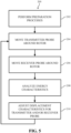
- FIG. 5 depicts an example process for aligning inspection probes of an inspection system.
- FIG. 5 is a flowchart depicting one example process 200 for aligning and maintaining alignment between a transmitter probe and a receiver probe of an inspection system while performing an inspection process on a rotor.
- initial preparation processes may be performed. Specifically, preparation processes may be performed on the rotor that may undergo the inspection process using the inspection system.
- the preparation processes may include, but are not limited to, removing the rotor from a housing and/or enclosure of the turbine system, and roughening the surface of the rotor. Roughening the surface of the rotor may include, for example, sandblasting the surface of the rotor to improve inspection results.
- Preparation processes can also include releasably coupling at least one transmitter probe and at least one receiver probe to the exposed surface of the rotor.
- the transmitter probe may be releasably coupled to the rotor on a first side of a feature of the rotor
- the receiver probe may be releasably coupled to the rotor on a second side of the feature.
- the second side of the feature may be opposite the first side.
- the feature may substantially block the line of sight between the transmitter probe and the receiver probe.
- the transmitter probe releasably coupled to the rotor may be moved on the rotor.
- the transmitter probe may be moved along the exposed surface of the rotor and/or may move circumferentially around the exposed surface of the rotor.
- the movement of the transmitter probe may automated and the transmitter probe may include a propulsion assembly configured to move the transmitter probe around the rotor.
- the movement of the transmitter probe may be done manually by an operator performing the inspection process on the rotor.
- the receiver probe releasably coupled to the rotor may also be moved around the rotor. Specifically, and similar to the movement of the transmitter probe in operation 204, the receiver probe may be moved along the exposed surface of the rotor and/or may move circumferentially around the exposed surface of the rotor. In non-limiting examples, the movement of the receiver probe may automated (e.g., a propulsion assembly), or alternatively, may be manual (e.g., operator).
- operation 204 and operation 206 may be performed simultaneously. That is, the movement of the transmitter probe in operation 204 and the movement of the receiver probe in operation 206 may happen simultaneously, such that both the transmitter probe and receiver probe are both moving along the exposed surface of the rotor. Additionally, it is understood that operation 204 and operation 206 may be performed independent of one another. That is, the movement of the transmitter probe may be independent from the movement of the receiver probe.
- energy characteristics for the energy received by the receiver probe may be analyzed. Specifically, energy characteristics including, but not limited to, a detected amplitude and/or a detected time of flight or travel for the energy received by the receiver probe may be analyzed. Analyzing the energy characteristics may also include determining a desired amplitude for the energy received by the receiver probe, and/or determining a desired time of flight for the energy received by the receiver probe. Determining the desired amplitude and/or time of flight may be accomplished when performing the analysis process in operation 208. Alternatively, determining the desired amplitude and/or time of flight may be accomplished prior to the analysis process in operation 208. For example, the desired amplitude and/or time of flight may be determined when performing the initial preparation processes in operation 202.
- Analyzing the energy characteristics may also include comparing the detected amplitude of the energy received by the receiver probe with the determined, desired amplitude, and determining if the detected amplitude differs from the desired amplitude. Also, analyzing the energy characteristics may include comparing the detected time of flight of the energy received by the receiver probe with the determined, desired time of flight, and determining if the detected time of flight differs from the desired time of flight. If it is determined that the detected amplitude and/or time of flight differs from the determined, desired amplitude and/or time of flight, then the analyzing of operation 208 may also include determining that the transmitter probe and the receiver probe are out of alignment and displacement characteristics of the transmitter probe and/or the receiver probe may require adjustment.
- displacement characteristics for the transmitter probe and/or the receiver probe may be adjusted based on the analyzed energy characteristics. Specifically, when it is determined that detected amplitude and/or time of flight differs from the determined, desired amplitude and/or time of flight, displacement characteristics for the transmitter probe and/or the receiver probe may be adjusted to realign and/or reposition the transmitter probe and the receiver probe on the rotor. The realignment and/or repositioning achieved by adjusting displacement characteristics of the transmitter probe and/or the receiver probe may allow the transmitter probe and the receiver probe to provide optimum inspection results when performing the inspection process on the rotor.
- Adjusting the displacement characteristics of the transmitter probe and/or the receiver probe may include altering a speed of the transmitter probe and/or the receiver probe, altering a circumferential position of the transmitter probe and/or the receiver probe with respect to the rotor, altering an axial position of the transmitter probe and/or the receiver probe with respect to the rotor, and/or altering an axial distance the transmitter probe and/or the receiver probe. Additionally, adjusting the displacement characteristics of the transmitter probe and/or the receiver probe may include axially aligning the transmitter probe and the receiver probe in response to the rotor undergoing the inspection process having a uniform and/or single diameter and circumference.
- adjusting the displacement characteristics of the transmitter probe and/or the receiver probe may include axially staggering the transmitter probe and the receiver probe in response to the transmitter probe being positioned on a first segment of the rotor having a first diameter and first circumference, and the receiver probe being positioned on a second segment of the rotor having a second diameter and second circumference.
- the second diameter and second circumference of the second segment may be smaller than the first diameter and first circumference of the first segment.
Landscapes
- Physics & Mathematics (AREA)
- General Physics & Mathematics (AREA)
- Health & Medical Sciences (AREA)
- Life Sciences & Earth Sciences (AREA)
- Chemical & Material Sciences (AREA)
- Analytical Chemistry (AREA)
- Biochemistry (AREA)
- General Health & Medical Sciences (AREA)
- Immunology (AREA)
- Pathology (AREA)
- Investigating Or Analyzing Materials By The Use Of Ultrasonic Waves (AREA)
Claims (9)
- Rotor (110), umfassend:eine Vielzahl von Merkmalen, die auf einer freiliegenden Oberfläche ausgebildet sind und sich von dieser erstrecken; undPrüfsystem, umfassend:mindestens eine Transmittersonde (132), die auf der freiliegenden Oberfläche und angrenzend an die Vielzahl von Merkmalen positioniert ist, wobei die mindestens eine Transmittersonde (132) konfiguriert ist, um Energie zu übertragen;mindestens eine Empfängersonde (138), die auf der freiliegenden Oberfläche positioniert und von der mindestens einen Transmittersonde (132) durch die Vielzahl von Merkmalen getrennt ist, wobei die mindestens eine Empfängersonde (138) konfiguriert ist, um die durch die mindestens einen Transmittersonde (132) übertragene Energie zu empfangen; undein Sondenausrichtungssystem (146), das mit der mindestens einen Transmittersonde (132) und der mindestens einen Empfängersonde (138) in Verbindung steht, wobei das Sondenausrichtungssystem (146) konfiguriert ist zum:
Analysieren einer Energiecharakteristik für die Ultraschallenergie, die durch die mindestens eine Empfängersonde (138) empfangen wird, um zu bestimmen, ob eine Verschiebungscharakteristik für mindestens eine der mindestens einen Transmittersonde (132) und der mindestens einen Empfängersonde (138) eine Anpassung erfordert; das Prüfsystem ferner umfassend:einen Codierer (158), der an einem Ende des Rotors (110) positioniert ist, wobei der Codierer (158) mit einer Mitte des Rotors (110) axial ausgerichtet ist;einen ersten Neigungsmesser (160), wobei der erste Neigungsmesser (160) mit der ersten Ultraschallsonde (132) gekoppelt, auf dieser ausgebildet und/oder positioniert ist; wobei der erste Neigungsmesser (160) in Verbindung mit dem Codierer (158) und dem Sondenausrichtungssystem (146) steht; undeinen zweiten Neigungsmesser (162), wobei der zweite Neigungsmesser (162) mit der zweiten Ultraschallsonde (138) gekoppelt, auf dieser ausgebildet und/oder positioniert ist; wobei der zweite Neigungsmesser (162) in Verbindung mit dem Codierer (158) und dem Sondenausrichtungssystem (146) steht. - Rotor nach Anspruch 1, wobei die mindestens eine Transmittersonde ein Ultraschall-Phased-Array-Wandler ist.
- Rotor nach Anspruch 1, wobei mindestens ein Merkmal der Vielzahl von Merkmalen eine Verbindung umfasst, die zwischen einem ersten Segment des Rotors und einem zweiten Segment des Rotors ausgebildet ist.
- Rotor nach Anspruch 3, wobei das erste Segment des Rotors einen ersten Durchmesser einschließt, der größer als ein zweiter Durchmesser des zweiten Segments des Rotors ist.
- Rotor nach Anspruch 4, wobei die mindestens eine Transmittersonde, die auf dem ersten Segment des Rotors positioniert ist, von der mindestens einen Empfängersonde axial versetzt ist, die auf dem zweiten Segment des Rotors positioniert ist.
- Verfahren nach Anspruch 1, wobei die Verschiebungscharakteristik mindestens eines umfasst von:einer Geschwindigkeit von mindestens einer der mindestens einen Transmittersonde und der mindestens einen Empfängersonde;einer Umfangsposition der mindestens einen Transmittersonde und der mindestens einen Empfängersonde in Bezug auf den Rotor; undeiner axiale Position der mindestens einen Transmittersonde und der mindestens einen Empfängersonde in Bezug auf das einzelne Merkmal aus der Vielzahl von Merkmalen, die die mindestens eine Transmittersonde und die mindestens eine Empfängersonde trennen.
- Verfahren zum Ausrichten von Prüfsonden zum Prüfen eines Turbinenrotors, das Verfahren umfassend: Bewegen einer ersten Ultraschallsonde entlang einer Oberfläche des Rotors, wobei die erste Ultraschallsonde konfiguriert ist, um Energie zu übertragen;Bewegen einer zweiten Ultraschallsonde entlang der Oberfläche des Rotors, wobei die zweite Ultraschallsonde konfiguriert ist, um die durch die erste Ultraschallsonde übertragene Energie zu empfangen;Analysieren einer Energiecharakteristik für die durch die zweite Ultraschallsonde empfangene Energie; undAnpassen einer Verschiebungscharakteristik für mindestens eine der ersten Ultraschallsonde und der zweiten Ultraschallsonde basierend auf der analysierten Energiecharakteristik; das Verfahren ferner umfassend:Verwenden eines Codierers, der auf einem Ende des Rotors positioniert ist, wobei der Codierer mit einer Mitte des Rotors axial ausgerichtet ist, um einen Referenzpunkt für den Rotor zu definieren;Verwenden eines ersten Neigungsmessers, der mit der ersten Ultraschallsonde gekoppelt, auf dieser ausgebildet und/oder positioniert ist, wobei der erste Neigungsmesser mit dem Codierer und dem Sondenausrichtungssystem in Verbindung steht, um eine erste Umfangsposition der ersten Ultraschallsonde zu bestimmen; undVerwenden eines zweiten Neigungsmessers, der mit der zweiten Ultraschallsonde gekoppelt, auf dieser ausgebildet und/oder positioniert ist, wobei der zweite Neigungsmesser mit dem Codierer und dem Sondenausrichtungssystem in Verbindung steht, um eine zweite Umfangsposition der zweiten Ultraschallsonde zu bestimmen.
- Verfahren nach Anspruch 7, ferner umfassend:Aufrauen der Oberfläche des Rotors;lösbares Koppeln der ersten Ultraschallsonde an den Rotor auf einer ersten Seite eines auf dem Rotor ausgebildeten Merkmals; undlösbares Koppeln der zweiten Ultraschallsonde an den Rotor auf einer zweiten Seite des auf dem Rotor ausgebildeten Merkmals, wobei die zweite Seite des Merkmals der ersten Seite gegenüberliegt.
- Verfahren nach Anspruch 8, ferner umfassend:Bestimmen einer gewünschten Amplitude für die Ultraschallenergie, die durch die zweite Ultraschallsonde empfangen wird;Bestimmen einer gewünschten Flugzeit für die Ultraschallenergie, die durch die zweite Ultraschallsonde empfangen wird; wobei das Analysieren der Energiecharakteristik ferner umfasst:Erfassen einer Amplitude der Ultraschallenergie, die durch die zweite Ultraschallsonde empfangen wird; Bestimmen, ob sich die erfasste Amplitude der Ultraschallenergie von der gewünschten Amplitude unterscheidet; Erfassen der Flugzeit der Ultraschallenergie, die von der ersten Ultraschallsonde übertragen und durch die zweite Ultraschallsonde empfangen wird; undBestimmen, ob sich die erfasste Flugzeit der Ultraschallenergie von der gewünschten Flugzeit unterscheidet.
Applications Claiming Priority (2)
| Application Number | Priority Date | Filing Date | Title |
|---|---|---|---|
| US15/200,082 US10151625B2 (en) | 2016-07-01 | 2016-07-01 | Inspection system for turbine rotors |
| PCT/US2017/040518 WO2018006076A1 (en) | 2016-07-01 | 2017-06-30 | Inspection system for turbine rotors |
Publications (2)
| Publication Number | Publication Date |
|---|---|
| EP3479112A1 EP3479112A1 (de) | 2019-05-08 |
| EP3479112B1 true EP3479112B1 (de) | 2024-09-25 |
Family
ID=59351115
Family Applications (1)
| Application Number | Title | Priority Date | Filing Date |
|---|---|---|---|
| EP17740213.8A Active EP3479112B1 (de) | 2016-07-01 | 2017-06-30 | Inspektionssystem für turbinenrotoren |
Country Status (4)
| Country | Link |
|---|---|
| US (3) | US10151625B2 (de) |
| EP (1) | EP3479112B1 (de) |
| JP (1) | JP6894452B2 (de) |
| WO (1) | WO2018006076A1 (de) |
Families Citing this family (3)
| Publication number | Priority date | Publication date | Assignee | Title |
|---|---|---|---|---|
| US10151625B2 (en) | 2016-07-01 | 2018-12-11 | General Electric Company | Inspection system for turbine rotors |
| DE102018208293A1 (de) * | 2018-05-25 | 2019-11-28 | Siemens Aktiengesellschaft | Prüfvorrichtung |
| JP7391537B2 (ja) * | 2019-05-20 | 2023-12-05 | 三菱重工業株式会社 | 超音波検査装置 |
Citations (1)
| Publication number | Priority date | Publication date | Assignee | Title |
|---|---|---|---|---|
| EP2902780A1 (de) * | 2014-01-30 | 2015-08-05 | Schneider Electric Industries SAS | Hilfssystem zur Ausrichtung für Ultraschallsender, Ultraschallsensoranordnung und Ausrichtungsverfahren |
Family Cites Families (19)
| Publication number | Priority date | Publication date | Assignee | Title |
|---|---|---|---|---|
| JPH03205552A (ja) * | 1989-10-13 | 1991-09-09 | Fuji Electric Co Ltd | 飛行機翼の自動超音波探傷装置 |
| US6347550B1 (en) * | 1998-07-22 | 2002-02-19 | Fraunhofer-Gesellschaft Zur Foerderung Der Angewandtzen Forschung E.V. | Ultrasonic test device |
| US7093491B2 (en) | 2004-04-09 | 2006-08-22 | General Electric Company | Apparatus and methods for automated turbine component inspections |
| US7190162B2 (en) * | 2004-07-23 | 2007-03-13 | General Electric Company | Methods and apparatus for inspecting a component |
| US7228741B2 (en) * | 2004-09-16 | 2007-06-12 | The Boeing Company | Alignment compensator for magnetically attracted inspecting apparatus and method |
| US7703327B2 (en) | 2004-09-16 | 2010-04-27 | The Boeing Company | Apparatus and method for area limited-access through transmission ultrasonic inspection |
| US7367236B2 (en) * | 2005-07-21 | 2008-05-06 | The Boeing Company | Non-destructive inspection system and associated method |
| JP2008089328A (ja) * | 2006-09-29 | 2008-04-17 | Hitachi Ltd | 渦電流探傷装置及び渦電流探傷方法 |
| US7579844B2 (en) * | 2007-03-09 | 2009-08-25 | Standard Aero Limited | Rotor blade system for rotor and rotor case inspection |
| DE102008002450B4 (de) * | 2008-04-11 | 2022-06-23 | Waygate Technologies Usa, Lp | Verfahren für die zerstörungsfreie Prüfung eines Prüflings mittels Ultraschall sowie Vorrichtung hierzu |
| JP2011089825A (ja) * | 2009-10-21 | 2011-05-06 | Ihi Aerospace Co Ltd | 屈折角制御装置、非接触超音波探傷装置、屈折角制御方法及び非接触超音波探傷方法 |
| US8438929B2 (en) * | 2010-09-02 | 2013-05-14 | Siemens Energy, Inc. | Phased array ultrasonic inspection system for turbine and generator rotor bore |
| US9117554B2 (en) * | 2010-12-02 | 2015-08-25 | Ge-Hitachi Nuclear Energy Americas Llc | Core shroud weld inspection systems and methods |
| DE102011050051B4 (de) | 2011-05-02 | 2021-10-21 | Deutsches Zentrum für Luft- und Raumfahrt e.V. | Transmissionsprüfvorrichtung und Transmissionsprüfverfahren zum Prüfen von Werkstücken |
| US8839673B2 (en) * | 2012-05-02 | 2014-09-23 | Siemens Energy, Inc. | System and method for industrial ultrasonic inspection using phased array probe and distance-gain-size flaw sizing |
| US9113825B2 (en) | 2012-07-10 | 2015-08-25 | Fujifilm Sonosite, Inc. | Ultrasonic probe and aligned needle guide system |
| US9586234B2 (en) | 2013-04-23 | 2017-03-07 | California Institute Of Technology | High temperature ultrasonic probe and pulse-echo probe mounting fixture for testing and blind alignment on steam pipes |
| US9482645B2 (en) * | 2013-05-17 | 2016-11-01 | General Electric Company | Ultrasonic detection method and ultrasonic analysis method |
| US10151625B2 (en) | 2016-07-01 | 2018-12-11 | General Electric Company | Inspection system for turbine rotors |
-
2016
- 2016-07-01 US US15/200,082 patent/US10151625B2/en active Active
-
2017
- 2017-06-30 WO PCT/US2017/040518 patent/WO2018006076A1/en not_active Ceased
- 2017-06-30 EP EP17740213.8A patent/EP3479112B1/de active Active
- 2017-06-30 JP JP2018567906A patent/JP6894452B2/ja active Active
- 2017-12-01 US US15/828,960 patent/US10036665B2/en active Active
-
2018
- 2018-06-25 US US16/017,326 patent/US10533891B2/en active Active
Patent Citations (1)
| Publication number | Priority date | Publication date | Assignee | Title |
|---|---|---|---|---|
| EP2902780A1 (de) * | 2014-01-30 | 2015-08-05 | Schneider Electric Industries SAS | Hilfssystem zur Ausrichtung für Ultraschallsender, Ultraschallsensoranordnung und Ausrichtungsverfahren |
Also Published As
| Publication number | Publication date |
|---|---|
| EP3479112A1 (de) | 2019-05-08 |
| US20180080811A1 (en) | 2018-03-22 |
| US10533891B2 (en) | 2020-01-14 |
| US20180003549A1 (en) | 2018-01-04 |
| JP6894452B2 (ja) | 2021-06-30 |
| US20180306636A1 (en) | 2018-10-25 |
| US10151625B2 (en) | 2018-12-11 |
| JP2019525147A (ja) | 2019-09-05 |
| US10036665B2 (en) | 2018-07-31 |
| WO2018006076A1 (en) | 2018-01-04 |
Similar Documents
| Publication | Publication Date | Title |
|---|---|---|
| US7302851B2 (en) | Methods and apparatus for rotary machinery inspection | |
| EP3479112B1 (de) | Inspektionssystem für turbinenrotoren | |
| US7888932B2 (en) | Surface flaw detection system to facilitate nondestructive inspection of a component and methods of assembling the same | |
| JP7358205B2 (ja) | タービンエンジンのロータブレードを監視するための方法およびシステム | |
| HK1212442A1 (en) | Flexible eddy current probe | |
| JPS62257053A (ja) | ヘツダ−の管孔を検査するための走査装置および方法 | |
| CN1967207B (zh) | 用于发电机转子齿检验的相控阵超声方法和系统 | |
| EP2623976A2 (de) | Gasturbinenscheibeninspektion mit flexibler Wirbelstromarraysonde | |
| JP4694576B2 (ja) | タービン部品の欠陥検出方法および装置 | |
| US6725722B1 (en) | Method of inspecting turbine wheel and bucket finger dovetails for cracks | |
| WO1996034280A1 (en) | Ultrasonic testing apparatus and method for multiple diameter oilfield tubulars | |
| US6019001A (en) | Process and device for the ultrasonic examination of disk elements of unknown contours shrunk onto shafts | |
| GB2421796A (en) | Nondestructive inspection method and system therefor | |
| US4577507A (en) | Method for the ultrasonic testing of discs shrink-fitted onto shafts in vicinity of shrink-fitted seats, and apparatus for carrying out the method | |
| KR100702578B1 (ko) | 다관절 로봇을 이용한 발전소의 증기터빈 자동 초음파검사장치 및 방법 | |
| US8395378B2 (en) | Nondestructive robotic inspection method and system therefor | |
| US20150300991A1 (en) | Manually operated small envelope scanner system | |
| JP6770409B2 (ja) | 押付力測定方法 | |
| KR102616475B1 (ko) | 열교환기의 전열관 와전류탐상검사 신호수집시스템및 방법 | |
| CN109073598A (zh) | 多阵列线圈的涡流探头和切换装置 | |
| KR102178955B1 (ko) | 로터 슬롯 초음파 검사장치 | |
| KR20180037596A (ko) | 비파괴 재료 시험 방법 | |
| CN112485334A (zh) | 一种动叶片叶根相控阵超声检测部件形状实时判别方法 | |
| EP2801699B1 (de) | Eintauchprüfsystem für eine Maschine und zugehöriges Betriebsverfahren | |
| Fukutomi et al. | Eddy‐Current Inspection of Cracking in Land‐Based Gas Turbine Blades |
Legal Events
| Date | Code | Title | Description |
|---|---|---|---|
| STAA | Information on the status of an ep patent application or granted ep patent |
Free format text: STATUS: UNKNOWN |
|
| STAA | Information on the status of an ep patent application or granted ep patent |
Free format text: STATUS: THE INTERNATIONAL PUBLICATION HAS BEEN MADE |
|
| PUAI | Public reference made under article 153(3) epc to a published international application that has entered the european phase |
Free format text: ORIGINAL CODE: 0009012 |
|
| STAA | Information on the status of an ep patent application or granted ep patent |
Free format text: STATUS: REQUEST FOR EXAMINATION WAS MADE |
|
| 17P | Request for examination filed |
Effective date: 20190201 |
|
| AK | Designated contracting states |
Kind code of ref document: A1 Designated state(s): AL AT BE BG CH CY CZ DE DK EE ES FI FR GB GR HR HU IE IS IT LI LT LU LV MC MK MT NL NO PL PT RO RS SE SI SK SM TR |
|
| AX | Request for extension of the european patent |
Extension state: BA ME |
|
| DAV | Request for validation of the european patent (deleted) | ||
| DAX | Request for extension of the european patent (deleted) | ||
| STAA | Information on the status of an ep patent application or granted ep patent |
Free format text: STATUS: EXAMINATION IS IN PROGRESS |
|
| 17Q | First examination report despatched |
Effective date: 20200623 |
|
| RAP1 | Party data changed (applicant data changed or rights of an application transferred) |
Owner name: GENERAL ELECTRIC TECHNOLOGY GMBH |
|
| GRAP | Despatch of communication of intention to grant a patent |
Free format text: ORIGINAL CODE: EPIDOSNIGR1 |
|
| STAA | Information on the status of an ep patent application or granted ep patent |
Free format text: STATUS: GRANT OF PATENT IS INTENDED |
|
| INTG | Intention to grant announced |
Effective date: 20240319 |
|
| GRAS | Grant fee paid |
Free format text: ORIGINAL CODE: EPIDOSNIGR3 |
|
| GRAA | (expected) grant |
Free format text: ORIGINAL CODE: 0009210 |
|
| STAA | Information on the status of an ep patent application or granted ep patent |
Free format text: STATUS: THE PATENT HAS BEEN GRANTED |
|
| AK | Designated contracting states |
Kind code of ref document: B1 Designated state(s): AL AT BE BG CH CY CZ DE DK EE ES FI FR GB GR HR HU IE IS IT LI LT LU LV MC MK MT NL NO PL PT RO RS SE SI SK SM TR |
|
| REG | Reference to a national code |
Ref country code: GB Ref legal event code: FG4D |
|
| REG | Reference to a national code |
Ref country code: CH Ref legal event code: EP |
|
| REG | Reference to a national code |
Ref country code: DE Ref legal event code: R096 Ref document number: 602017085057 Country of ref document: DE |
|
| REG | Reference to a national code |
Ref country code: IE Ref legal event code: FG4D |
|
| REG | Reference to a national code |
Ref country code: LT Ref legal event code: MG9D |
|
| PG25 | Lapsed in a contracting state [announced via postgrant information from national office to epo] |
Ref country code: NO Free format text: LAPSE BECAUSE OF FAILURE TO SUBMIT A TRANSLATION OF THE DESCRIPTION OR TO PAY THE FEE WITHIN THE PRESCRIBED TIME-LIMIT Effective date: 20241225 |
|
| PG25 | Lapsed in a contracting state [announced via postgrant information from national office to epo] |
Ref country code: GR Free format text: LAPSE BECAUSE OF FAILURE TO SUBMIT A TRANSLATION OF THE DESCRIPTION OR TO PAY THE FEE WITHIN THE PRESCRIBED TIME-LIMIT Effective date: 20241226 Ref country code: FI Free format text: LAPSE BECAUSE OF FAILURE TO SUBMIT A TRANSLATION OF THE DESCRIPTION OR TO PAY THE FEE WITHIN THE PRESCRIBED TIME-LIMIT Effective date: 20240925 |
|
| PG25 | Lapsed in a contracting state [announced via postgrant information from national office to epo] |
Ref country code: BG Free format text: LAPSE BECAUSE OF FAILURE TO SUBMIT A TRANSLATION OF THE DESCRIPTION OR TO PAY THE FEE WITHIN THE PRESCRIBED TIME-LIMIT Effective date: 20240925 |
|
| PG25 | Lapsed in a contracting state [announced via postgrant information from national office to epo] |
Ref country code: LV Free format text: LAPSE BECAUSE OF FAILURE TO SUBMIT A TRANSLATION OF THE DESCRIPTION OR TO PAY THE FEE WITHIN THE PRESCRIBED TIME-LIMIT Effective date: 20240925 |
|
| PG25 | Lapsed in a contracting state [announced via postgrant information from national office to epo] |
Ref country code: RS Free format text: LAPSE BECAUSE OF FAILURE TO SUBMIT A TRANSLATION OF THE DESCRIPTION OR TO PAY THE FEE WITHIN THE PRESCRIBED TIME-LIMIT Effective date: 20241225 |
|
| REG | Reference to a national code |
Ref country code: NL Ref legal event code: MP Effective date: 20240925 |
|
| PG25 | Lapsed in a contracting state [announced via postgrant information from national office to epo] |
Ref country code: RS Free format text: LAPSE BECAUSE OF FAILURE TO SUBMIT A TRANSLATION OF THE DESCRIPTION OR TO PAY THE FEE WITHIN THE PRESCRIBED TIME-LIMIT Effective date: 20241225 Ref country code: NO Free format text: LAPSE BECAUSE OF FAILURE TO SUBMIT A TRANSLATION OF THE DESCRIPTION OR TO PAY THE FEE WITHIN THE PRESCRIBED TIME-LIMIT Effective date: 20241225 Ref country code: LV Free format text: LAPSE BECAUSE OF FAILURE TO SUBMIT A TRANSLATION OF THE DESCRIPTION OR TO PAY THE FEE WITHIN THE PRESCRIBED TIME-LIMIT Effective date: 20240925 Ref country code: GR Free format text: LAPSE BECAUSE OF FAILURE TO SUBMIT A TRANSLATION OF THE DESCRIPTION OR TO PAY THE FEE WITHIN THE PRESCRIBED TIME-LIMIT Effective date: 20241226 Ref country code: FI Free format text: LAPSE BECAUSE OF FAILURE TO SUBMIT A TRANSLATION OF THE DESCRIPTION OR TO PAY THE FEE WITHIN THE PRESCRIBED TIME-LIMIT Effective date: 20240925 Ref country code: BG Free format text: LAPSE BECAUSE OF FAILURE TO SUBMIT A TRANSLATION OF THE DESCRIPTION OR TO PAY THE FEE WITHIN THE PRESCRIBED TIME-LIMIT Effective date: 20240925 |
|
| REG | Reference to a national code |
Ref country code: AT Ref legal event code: MK05 Ref document number: 1727027 Country of ref document: AT Kind code of ref document: T Effective date: 20240925 |
|
| PG25 | Lapsed in a contracting state [announced via postgrant information from national office to epo] |
Ref country code: NL Free format text: LAPSE BECAUSE OF FAILURE TO SUBMIT A TRANSLATION OF THE DESCRIPTION OR TO PAY THE FEE WITHIN THE PRESCRIBED TIME-LIMIT Effective date: 20240925 |
|
| PG25 | Lapsed in a contracting state [announced via postgrant information from national office to epo] |
Ref country code: IS Free format text: LAPSE BECAUSE OF FAILURE TO SUBMIT A TRANSLATION OF THE DESCRIPTION OR TO PAY THE FEE WITHIN THE PRESCRIBED TIME-LIMIT Effective date: 20250125 Ref country code: PT Free format text: LAPSE BECAUSE OF FAILURE TO SUBMIT A TRANSLATION OF THE DESCRIPTION OR TO PAY THE FEE WITHIN THE PRESCRIBED TIME-LIMIT Effective date: 20250127 |
|
| PG25 | Lapsed in a contracting state [announced via postgrant information from national office to epo] |
Ref country code: RO Free format text: LAPSE BECAUSE OF FAILURE TO SUBMIT A TRANSLATION OF THE DESCRIPTION OR TO PAY THE FEE WITHIN THE PRESCRIBED TIME-LIMIT Effective date: 20240925 Ref country code: SM Free format text: LAPSE BECAUSE OF FAILURE TO SUBMIT A TRANSLATION OF THE DESCRIPTION OR TO PAY THE FEE WITHIN THE PRESCRIBED TIME-LIMIT Effective date: 20240925 |
|
| PG25 | Lapsed in a contracting state [announced via postgrant information from national office to epo] |
Ref country code: ES Free format text: LAPSE BECAUSE OF FAILURE TO SUBMIT A TRANSLATION OF THE DESCRIPTION OR TO PAY THE FEE WITHIN THE PRESCRIBED TIME-LIMIT Effective date: 20240925 |
|
| PG25 | Lapsed in a contracting state [announced via postgrant information from national office to epo] |
Ref country code: AT Free format text: LAPSE BECAUSE OF FAILURE TO SUBMIT A TRANSLATION OF THE DESCRIPTION OR TO PAY THE FEE WITHIN THE PRESCRIBED TIME-LIMIT Effective date: 20240925 Ref country code: EE Free format text: LAPSE BECAUSE OF FAILURE TO SUBMIT A TRANSLATION OF THE DESCRIPTION OR TO PAY THE FEE WITHIN THE PRESCRIBED TIME-LIMIT Effective date: 20240925 |
|
| PG25 | Lapsed in a contracting state [announced via postgrant information from national office to epo] |
Ref country code: PL Free format text: LAPSE BECAUSE OF FAILURE TO SUBMIT A TRANSLATION OF THE DESCRIPTION OR TO PAY THE FEE WITHIN THE PRESCRIBED TIME-LIMIT Effective date: 20240925 Ref country code: CZ Free format text: LAPSE BECAUSE OF FAILURE TO SUBMIT A TRANSLATION OF THE DESCRIPTION OR TO PAY THE FEE WITHIN THE PRESCRIBED TIME-LIMIT Effective date: 20240925 |
|
| PG25 | Lapsed in a contracting state [announced via postgrant information from national office to epo] |
Ref country code: SK Free format text: LAPSE BECAUSE OF FAILURE TO SUBMIT A TRANSLATION OF THE DESCRIPTION OR TO PAY THE FEE WITHIN THE PRESCRIBED TIME-LIMIT Effective date: 20240925 |
|
| REG | Reference to a national code |
Ref country code: DE Ref legal event code: R097 Ref document number: 602017085057 Country of ref document: DE |
|
| PGFP | Annual fee paid to national office [announced via postgrant information from national office to epo] |
Ref country code: DE Payment date: 20250520 Year of fee payment: 9 |
|
| PG25 | Lapsed in a contracting state [announced via postgrant information from national office to epo] |
Ref country code: DK Free format text: LAPSE BECAUSE OF FAILURE TO SUBMIT A TRANSLATION OF THE DESCRIPTION OR TO PAY THE FEE WITHIN THE PRESCRIBED TIME-LIMIT Effective date: 20240925 |
|
| PGFP | Annual fee paid to national office [announced via postgrant information from national office to epo] |
Ref country code: IT Payment date: 20250520 Year of fee payment: 9 |
|
| PGFP | Annual fee paid to national office [announced via postgrant information from national office to epo] |
Ref country code: FR Payment date: 20250520 Year of fee payment: 9 |
|
| PLBE | No opposition filed within time limit |
Free format text: ORIGINAL CODE: 0009261 |
|
| STAA | Information on the status of an ep patent application or granted ep patent |
Free format text: STATUS: NO OPPOSITION FILED WITHIN TIME LIMIT |
|
| 26N | No opposition filed |
Effective date: 20250626 |
|
| PG25 | Lapsed in a contracting state [announced via postgrant information from national office to epo] |
Ref country code: SE Free format text: LAPSE BECAUSE OF FAILURE TO SUBMIT A TRANSLATION OF THE DESCRIPTION OR TO PAY THE FEE WITHIN THE PRESCRIBED TIME-LIMIT Effective date: 20240925 |
|
| PGFP | Annual fee paid to national office [announced via postgrant information from national office to epo] |
Ref country code: CH Payment date: 20250701 Year of fee payment: 9 |
|
| PG25 | Lapsed in a contracting state [announced via postgrant information from national office to epo] |
Ref country code: HR Free format text: LAPSE BECAUSE OF FAILURE TO SUBMIT A TRANSLATION OF THE DESCRIPTION OR TO PAY THE FEE WITHIN THE PRESCRIBED TIME-LIMIT Effective date: 20240925 |
|
| PG25 | Lapsed in a contracting state [announced via postgrant information from national office to epo] |
Ref country code: MC Free format text: LAPSE BECAUSE OF FAILURE TO SUBMIT A TRANSLATION OF THE DESCRIPTION OR TO PAY THE FEE WITHIN THE PRESCRIBED TIME-LIMIT Effective date: 20240925 |