EP3478523B2 - Hybridantriebsmodul für einen kraftfahrzeugantriebsstrang und kraftfahrzeugantriebsstrang - Google Patents
Hybridantriebsmodul für einen kraftfahrzeugantriebsstrang und kraftfahrzeugantriebsstrang Download PDFInfo
- Publication number
- EP3478523B2 EP3478523B2 EP17724010.8A EP17724010A EP3478523B2 EP 3478523 B2 EP3478523 B2 EP 3478523B2 EP 17724010 A EP17724010 A EP 17724010A EP 3478523 B2 EP3478523 B2 EP 3478523B2
- Authority
- EP
- European Patent Office
- Prior art keywords
- torsional vibration
- drive module
- hybrid drive
- motor vehicle
- damping device
- Prior art date
- Legal status (The legal status is an assumption and is not a legal conclusion. Google has not performed a legal analysis and makes no representation as to the accuracy of the status listed.)
- Active
Links
Images

Classifications
-
- F—MECHANICAL ENGINEERING; LIGHTING; HEATING; WEAPONS; BLASTING
- F16—ENGINEERING ELEMENTS AND UNITS; GENERAL MEASURES FOR PRODUCING AND MAINTAINING EFFECTIVE FUNCTIONING OF MACHINES OR INSTALLATIONS; THERMAL INSULATION IN GENERAL
- F16F—SPRINGS; SHOCK-ABSORBERS; MEANS FOR DAMPING VIBRATION
- F16F15/00—Suppression of vibrations in systems; Means or arrangements for avoiding or reducing out-of-balance forces, e.g. due to motion
- F16F15/10—Suppression of vibrations in rotating systems by making use of members moving with the system
- F16F15/12—Suppression of vibrations in rotating systems by making use of members moving with the system using elastic members or friction-damping members, e.g. between a rotating shaft and a gyratory mass mounted thereon
- F16F15/121—Suppression of vibrations in rotating systems by making use of members moving with the system using elastic members or friction-damping members, e.g. between a rotating shaft and a gyratory mass mounted thereon using springs as elastic members, e.g. metallic springs
- F16F15/123—Wound springs
- F16F15/12353—Combinations of dampers, e.g. with multiple plates, multiple spring sets, i.e. complex configurations
-
- B—PERFORMING OPERATIONS; TRANSPORTING
- B60—VEHICLES IN GENERAL
- B60K—ARRANGEMENT OR MOUNTING OF PROPULSION UNITS OR OF TRANSMISSIONS IN VEHICLES; ARRANGEMENT OR MOUNTING OF PLURAL DIVERSE PRIME-MOVERS IN VEHICLES; AUXILIARY DRIVES FOR VEHICLES; INSTRUMENTATION OR DASHBOARDS FOR VEHICLES; ARRANGEMENTS IN CONNECTION WITH COOLING, AIR INTAKE, GAS EXHAUST OR FUEL SUPPLY OF PROPULSION UNITS IN VEHICLES
- B60K6/00—Arrangement or mounting of plural diverse prime-movers for mutual or common propulsion, e.g. hybrid propulsion systems comprising electric motors and internal combustion engines
- B60K6/20—Arrangement or mounting of plural diverse prime-movers for mutual or common propulsion, e.g. hybrid propulsion systems comprising electric motors and internal combustion engines the prime-movers consisting of electric motors and internal combustion engines, e.g. HEVs
- B60K6/22—Arrangement or mounting of plural diverse prime-movers for mutual or common propulsion, e.g. hybrid propulsion systems comprising electric motors and internal combustion engines the prime-movers consisting of electric motors and internal combustion engines, e.g. HEVs characterised by apparatus, components or means specially adapted for HEVs
- B60K6/40—Arrangement or mounting of plural diverse prime-movers for mutual or common propulsion, e.g. hybrid propulsion systems comprising electric motors and internal combustion engines the prime-movers consisting of electric motors and internal combustion engines, e.g. HEVs characterised by apparatus, components or means specially adapted for HEVs characterised by the assembly or relative disposition of components
-
- B—PERFORMING OPERATIONS; TRANSPORTING
- B60—VEHICLES IN GENERAL
- B60K—ARRANGEMENT OR MOUNTING OF PROPULSION UNITS OR OF TRANSMISSIONS IN VEHICLES; ARRANGEMENT OR MOUNTING OF PLURAL DIVERSE PRIME-MOVERS IN VEHICLES; AUXILIARY DRIVES FOR VEHICLES; INSTRUMENTATION OR DASHBOARDS FOR VEHICLES; ARRANGEMENTS IN CONNECTION WITH COOLING, AIR INTAKE, GAS EXHAUST OR FUEL SUPPLY OF PROPULSION UNITS IN VEHICLES
- B60K6/00—Arrangement or mounting of plural diverse prime-movers for mutual or common propulsion, e.g. hybrid propulsion systems comprising electric motors and internal combustion engines
- B60K6/20—Arrangement or mounting of plural diverse prime-movers for mutual or common propulsion, e.g. hybrid propulsion systems comprising electric motors and internal combustion engines the prime-movers consisting of electric motors and internal combustion engines, e.g. HEVs
- B60K6/42—Arrangement or mounting of plural diverse prime-movers for mutual or common propulsion, e.g. hybrid propulsion systems comprising electric motors and internal combustion engines the prime-movers consisting of electric motors and internal combustion engines, e.g. HEVs characterised by the architecture of the hybrid electric vehicle
- B60K6/48—Parallel type
-
- F—MECHANICAL ENGINEERING; LIGHTING; HEATING; WEAPONS; BLASTING
- F16—ENGINEERING ELEMENTS AND UNITS; GENERAL MEASURES FOR PRODUCING AND MAINTAINING EFFECTIVE FUNCTIONING OF MACHINES OR INSTALLATIONS; THERMAL INSULATION IN GENERAL
- F16F—SPRINGS; SHOCK-ABSORBERS; MEANS FOR DAMPING VIBRATION
- F16F15/00—Suppression of vibrations in systems; Means or arrangements for avoiding or reducing out-of-balance forces, e.g. due to motion
- F16F15/10—Suppression of vibrations in rotating systems by making use of members moving with the system
- F16F15/12—Suppression of vibrations in rotating systems by making use of members moving with the system using elastic members or friction-damping members, e.g. between a rotating shaft and a gyratory mass mounted thereon
- F16F15/131—Suppression of vibrations in rotating systems by making use of members moving with the system using elastic members or friction-damping members, e.g. between a rotating shaft and a gyratory mass mounted thereon the rotating system comprising two or more gyratory masses
- F16F15/133—Suppression of vibrations in rotating systems by making use of members moving with the system using elastic members or friction-damping members, e.g. between a rotating shaft and a gyratory mass mounted thereon the rotating system comprising two or more gyratory masses using springs as elastic members, e.g. metallic springs
- F16F15/134—Wound springs
- F16F15/13469—Combinations of dampers, e.g. with multiple plates, multiple spring sets, i.e. complex configurations
-
- F—MECHANICAL ENGINEERING; LIGHTING; HEATING; WEAPONS; BLASTING
- F16—ENGINEERING ELEMENTS AND UNITS; GENERAL MEASURES FOR PRODUCING AND MAINTAINING EFFECTIVE FUNCTIONING OF MACHINES OR INSTALLATIONS; THERMAL INSULATION IN GENERAL
- F16F—SPRINGS; SHOCK-ABSORBERS; MEANS FOR DAMPING VIBRATION
- F16F15/00—Suppression of vibrations in systems; Means or arrangements for avoiding or reducing out-of-balance forces, e.g. due to motion
- F16F15/10—Suppression of vibrations in rotating systems by making use of members moving with the system
- F16F15/14—Suppression of vibrations in rotating systems by making use of members moving with the system using masses freely rotating with the system, i.e. uninvolved in transmitting driveline torque, e.g. rotative dynamic dampers
- F16F15/1407—Suppression of vibrations in rotating systems by making use of members moving with the system using masses freely rotating with the system, i.e. uninvolved in transmitting driveline torque, e.g. rotative dynamic dampers the rotation being limited with respect to the driving means
- F16F15/145—Masses mounted with play with respect to driving means thus enabling free movement over a limited range
-
- B—PERFORMING OPERATIONS; TRANSPORTING
- B60—VEHICLES IN GENERAL
- B60K—ARRANGEMENT OR MOUNTING OF PROPULSION UNITS OR OF TRANSMISSIONS IN VEHICLES; ARRANGEMENT OR MOUNTING OF PLURAL DIVERSE PRIME-MOVERS IN VEHICLES; AUXILIARY DRIVES FOR VEHICLES; INSTRUMENTATION OR DASHBOARDS FOR VEHICLES; ARRANGEMENTS IN CONNECTION WITH COOLING, AIR INTAKE, GAS EXHAUST OR FUEL SUPPLY OF PROPULSION UNITS IN VEHICLES
- B60K6/00—Arrangement or mounting of plural diverse prime-movers for mutual or common propulsion, e.g. hybrid propulsion systems comprising electric motors and internal combustion engines
- B60K6/20—Arrangement or mounting of plural diverse prime-movers for mutual or common propulsion, e.g. hybrid propulsion systems comprising electric motors and internal combustion engines the prime-movers consisting of electric motors and internal combustion engines, e.g. HEVs
- B60K6/42—Arrangement or mounting of plural diverse prime-movers for mutual or common propulsion, e.g. hybrid propulsion systems comprising electric motors and internal combustion engines the prime-movers consisting of electric motors and internal combustion engines, e.g. HEVs characterised by the architecture of the hybrid electric vehicle
- B60K6/48—Parallel type
- B60K2006/4825—Electric machine connected or connectable to gearbox input shaft
-
- B—PERFORMING OPERATIONS; TRANSPORTING
- B60—VEHICLES IN GENERAL
- B60Y—INDEXING SCHEME RELATING TO ASPECTS CROSS-CUTTING VEHICLE TECHNOLOGY
- B60Y2400/00—Special features of vehicle units
- B60Y2400/48—Vibration dampers, e.g. dual mass flywheels
-
- Y—GENERAL TAGGING OF NEW TECHNOLOGICAL DEVELOPMENTS; GENERAL TAGGING OF CROSS-SECTIONAL TECHNOLOGIES SPANNING OVER SEVERAL SECTIONS OF THE IPC; TECHNICAL SUBJECTS COVERED BY FORMER USPC CROSS-REFERENCE ART COLLECTIONS [XRACs] AND DIGESTS
- Y02—TECHNOLOGIES OR APPLICATIONS FOR MITIGATION OR ADAPTATION AGAINST CLIMATE CHANGE
- Y02T—CLIMATE CHANGE MITIGATION TECHNOLOGIES RELATED TO TRANSPORTATION
- Y02T10/00—Road transport of goods or passengers
- Y02T10/60—Other road transportation technologies with climate change mitigation effect
- Y02T10/62—Hybrid vehicles
Definitions
- the invention relates to a torsional vibration damping system for a motor vehicle drive train, comprising an input side and an output side, which are connected via a damping device to at least one torsional vibration damper and a vibration absorber, wherein the damping device and the vibration absorber are designed for arrangement in a wet space of a housing.
- the invention further relates to a hybrid drive module comprising a housing in which a torsional vibration damping system and an electric machine are accommodated, wherein the torsional vibration damping system is composed of a damping device and a vibration absorber, which are provided between an input side and an output side of the torsional vibration damping system and are placed in a wet space of the housing, wherein the torsional vibration damping system is connected on its output side to a separating clutch, via which the torsional vibration damping system can be connected to an output side of the hybrid drive module, to which the electric machine is also connected.
- the invention relates to a motor vehicle transmission and a motor vehicle drive train with an aforementioned hybrid drive module.
- a motor vehicle drive train forms a system capable of vibration in which rotational irregularities can occur.
- the motor vehicle drive train includes a drive machine in the form of an internal combustion engine, these rotational irregularities or torsional vibrations are already introduced into the system by the drive machine, since the way the internal combustion engine operates means that periodically acting rotational forces overlap with the actual rotational movement of the internal combustion engine's crankshaft. Since torsional vibrations noticeably reduce driving comfort and can also result in high component loads and even damage, measures are usually taken in a motor vehicle drive train to dampen and thus reduce torsional vibrations.
- a torsional vibration damping system is often provided between the internal combustion engine and a motor vehicle transmission, in which torsional vibrations in the relevant frequency range are specifically dampened with the help of at least one torsional vibration damper.
- a torsional vibration damper which can be a dual-mass flywheel, for example, is designed for the corresponding frequency range.
- a torsional vibration damping system often also includes a vibration absorber, which causes a targeted detuning of the vibrating system by means of speed-dependent deflection of additional masses, thus also reducing torsional vibrations.
- a torsional vibration damping system as described above is increasingly also part of a hybrid drive module, in which an electric machine is also provided to implement certain driving functions.
- This electric machine is usually arranged on an output side of the hybrid drive module, whereby the output side can be connected to an input side of the hybrid drive module via the intermediate torsional vibration damping system by closing a separating clutch.
- the output side can be separated from the input side by opening the separating clutch, thus enabling the electric machine to operate without a mechanical connection to the internal combustion engine.
- the torsional vibration damping system consists of a damping device with a torsional vibration damper and a vibration absorber, which are provided between an input side and an output side of the torsional vibration damping system and are placed in a wet space of the housing.
- the torsional vibration damper works according to the power split principle in that the input side and the output side are further coupled to one another via a superposition gear.
- the output side of the torsional vibration damping system is also connected to a separating clutch, via which the torsional vibration damping system can be connected to an output side of the hybrid drive module.
- a rotor of the electric machine is then also connected to this output side.
- Claim 9 relates to a motor vehicle drive train.
- a torsional vibration damping system in a hybrid drive module comprises an input side and an output side, which are connected to at least one torsional vibration damper and one vibration absorber via a damping device.
- the damping device and the vibration absorber are designed for arrangement in a wet space of a housing.
- the torsional vibration damping system therefore has a damping device that includes at least one torsional vibration damper.
- a torsional vibration damper is a system in which a primary side and a secondary side are torsionally elastically coupled to one another via at least one intermediate element, whereby vibration isolation is achieved.
- the at least one intermediate element is preferably a spring element in the form of a coil spring.
- the torsional vibration damper is preferably designed as a dual-mass flywheel. If necessary, hydraulic damping can also be provided.
- the vibration damper is preferably formed by several masses which are deflected depending on the speed and in doing so deliberately detune the vibrating system. It is particularly preferred that the masses are pivotally connected at one end so that they can be deflected radially outwards under the influence of the speed.
- a "wet space" of a housing is understood to mean a delimited space in the respective housing in which lubricant, preferably in the form of oil, is accommodated and in which the components located therein can come into contact with the lubricant.
- the wet space of the housing is filled with lubricant up to a defined level in order to realize a splash lubrication of components accommodated in the housing.
- damping device and the vibration absorber are designed for installation in a wet room means in this case that the damping device and the vibration absorber are designed in terms of their lubrication to be installed in a wet room of a housing.
- the damping device and the vibration absorber are supplied with oil from the radial inside in particular and the oil is then simply drained radially outwards. In comparison to arranging the damping device and the vibration absorber in a dry room, this makes it possible to supply these components with lubricant without having to prevent the lubricant from escaping radially outwards.
- the damping device comprises two torsional vibration dampers.
- the damping device is composed of two torsional vibration dampers, which are arranged together with the vibration absorber between the input side and the output side of the torsional vibration damping system.
- Such a design of a torsional vibration damping system has the advantage that better damping of torsional vibrations in the motor vehicle drive train can be achieved by providing two torsional vibration dampers. This is because the arrangement of two torsional vibration dampers enables the torsional stiffness of the damping device to be reduced. Overall, a torsional vibration damping system designed according to the invention can therefore achieve reliable damping of torsional vibrations while simultaneously reliably lubricating components of the system.
- the damping device and the vibration absorber are also designed for installation in a wet room of a housing, the damping device is only formed by a torsional vibration damper.
- the input side and the output side of the torsional vibration damping system are only coupled to one another via the intermediate damping device and the vibration absorber.
- a power-split structure here by assigning a superposition gear to the torsional vibration damping system, as is also the case, for example, in the DE 10 2012 219 728 A1 disclosed.
- a superposition gear could consist of one or more planetary stages.
- the torsional vibration dampers of the damping device are connected in series.
- the torsional vibration dampers are therefore arranged one after the other in the direction of force flow from the input side to the output side.
- the vibration absorber is then integrated between the torsional vibration dampers, although it could alternatively be located on the input side or output side of both torsional vibration dampers.
- the torsional vibration dampers are arranged in a common plane.
- the vibration absorber is provided axially directly next to the torsional vibration dampers and radially at the level of the radially inner torsional vibration damper.
- the torsional vibration dampers are combined to form a two-row dual-mass flywheel.
- the two torsional vibration dampers form a unit, although they can alternatively be separate from one another as independent components. In the latter case, the torsional vibration dampers can then have a corresponding or different structure.
- the damping device and/or the vibration absorber are radially surrounded by a fixed shell at least in a vertically lower area.
- a stationary shell is provided which lies vertically below the damping device and/or the vibration absorber and radially encloses the damping device or the vibration absorber or both there.
- the shell advantageously prevents the damping device and the vibration absorber from dipping too deeply into lubricant vertically below, which leads to increased splashing losses and foaming of the oil. This is because the shell can create an area with a lower lubricant level in the area of the damping device and the vibration absorber than in the surrounding area of the wet room.
- the shell is particularly preferably used when the torsional vibration dampers are arranged in one plane.
- the shell preferably surrounds the damping device and the vibration absorber.
- a hollow shaft is provided on the input side of the torsional vibration damping system, into which a further shaft is inserted and connected to it in a rotationally fixed manner.
- a connection to the damping device and the vibration absorber is established via the further shaft, with a sealing shield being applied to the hollow shaft, which serves to separate the wet space from a dry space in the housing.
- the hollow shaft and the further shaft are connected to one another via a driving toothing, which is implemented as a press fit. The press fit prevents the driving toothing from turning over during load changes in the drive train and thus noise being generated in the area of the torsional vibration damping system, especially since torsional vibrations in the area of the driving toothing are not yet dampened.
- the hollow shaft, the additional shaft, the damping device, the vibration damper and the sealing shield form a pre-assembled unit.
- This has the advantage that the sealing shield can be arranged on the hollow shaft with a seal despite the drive teeth being implemented as a press fit. Furthermore, the formation of a pre-assembled unit reduces the assembly effort, since this unit only needs to be arranged in the motor vehicle drive train during assembly.
- the torsional vibration damping system is part of a hybrid drive module according to the invention for a motor vehicle drive train.
- This hybrid drive module comprises a housing in which the torsional vibration damping system and an electric machine are accommodated.
- the torsional vibration damping system is composed of a damping device and a vibration absorber, which are provided between an input side and an output side of the torsional vibration damping system and are placed in a wet space of the housing.
- the torsional vibration damping system is connected on its output side to a separating clutch, via which the torsional vibration damping system can be connected to an output side of the hybrid drive module, to which the electric machine is also connected.
- the damping device then comprises two torsional vibration dampers.
- a torsional vibration damping system designed according to the invention with two torsional vibration dampers, suitable damping of torsional vibrations can also be achieved in the area of a hybrid drive module.
- various functions can be implemented using the electric machine of the hybrid drive module by operating it as a generator or electric motor.
- the electric machine can support the drive machine by feeding in additional drive torque (boosting) or also implement a purely electric drive.
- a start-stop function can be implemented using the electric machine by towing the internal combustion engine during the starting process.
- generator operation electricity can be generated during operation via the drive machine or it can be recovered during braking processes (recuperation).
- the connection to the drive machine must be separated by opening the separating clutch.
- the electric machine is designed in particular as a permanently excited synchronous machine.
- a rotor of the electric machine is preferably connected directly to the output side of the hybrid drive module in a rotationally fixed manner, whereby a rotor hub of the rotor can be plugged directly onto a drive shaft of a motor vehicle transmission following in the motor vehicle drive train.
- the rotor of the electric machine can be supported via the bearing of the drive shaft of the motor vehicle transmission.
- fits are provided between the rotor hub and the drive shaft of the motor vehicle transmission in order to mount the rotor of the electric machine accordingly on the drive shaft. to center.
- a stator of the electric machine is in particular attached to the housing of the hybrid drive module, whereby a structure is preferably selected in which a stator carrier is attached to an intermediate wall, preferably via screw connections.
- This intermediate wall then also serves to accommodate a bearing for the transmission input shaft, so that the stator is attached and the rotor is mounted on the same part of the housing.
- the intermediate wall separates the wet space from the interior of a subsequent motor vehicle transmission.
- the intermediate wall also preferably takes on the function of supplying oil to certain components and is interspersed with corresponding oil lines for this purpose.
- any radial offset that may exist in the torsional vibration damping system is preferably compensated for in the torsional vibration damper on the output side of the torsional vibration damping system. This is done in particular in a spring set of the torsional vibration damper.
- a "radial offset” is understood to mean an unwanted radial positional deviation between components to be connected to one another, which occurs, for example, due to manufacturing tolerances or running inaccuracies of components.
- an axial offset in the hybrid drive module is compensated in the separating clutch, which is preferably designed as a multi-disk clutch for this purpose.
- the axial offset is then compensated in particular in a multi-disk toothing of the multi-disk clutch, via which disks are guided in a rotationally fixed and axially movable manner.
- an "axial offset" is to be understood as an unwanted axial positional deviation between components to be connected to one another, which occurs, for example, due to manufacturing tolerances.
- the axial offset can be imposed on the hybrid drive module within the motor vehicle drive train from the outside by components of the motor vehicle drive train, between which the hybrid drive module is located, ensuring the axial offset. This positional deviation is now compensated in the present case by the separating clutch. This means that an axial bearing between the torsional vibration damping system and the output side of the hybrid drive module can be omitted.
- the torsional vibration damping system used in the hybrid drive module is designed according to one of the variants described above.
- the hybrid drive module is in particular part of a motor vehicle drive train and is located here in particular between a drive engine and a downstream motor vehicle transmission.
- the hybrid drive module can also be part of the motor vehicle transmission.
- the hybrid drive module and motor vehicle transmission can be accommodated in a common housing, which is in particular a transmission housing of the motor vehicle transmission.
- Fig.1 shows a schematic view of a motor vehicle drive train 1, which is in particular the drive train of a motor vehicle in the form of a passenger car.
- the motor vehicle drive train 1 comprises a drive machine 2 in the form of an internal combustion engine, which can be connected on the output side to a motor vehicle transmission 4 via an intermediate hybrid drive module 3.
- the motor vehicle transmission 4 is preferably designed as an automatic transmission in planetary design and is connected on the output side to further, subsequent components 5 of the motor vehicle drive train - only indicated here - for example to a longitudinal or transverse differential.
- the hybrid drive module 3 and the motor vehicle transmission 4 are accommodated in a common housing 6, which is in particular a transmission housing of the motor vehicle transmission 4.
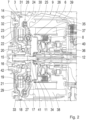
- the motor vehicle drive train 1 consists of Fig.1 shown in section in the area of the hybrid drive module 3, the hybrid drive module 3 being designed in accordance with a preferred embodiment of the invention.
- the hybrid drive module 3 is composed of a torsional vibration damping system 7, a separating clutch 8 and an electric machine 9.
- the hybrid drive module 3 is connected on a drive side 10 within the motor vehicle drive train 1 in a rotationally fixed manner to a crankshaft of the drive machine 2 and is connected on an output side 11 in a rotationally fixed manner to a drive shaft 12 of the subsequent motor vehicle transmission 4.
- the drive side 10 is formed by a flexible connecting plate 13, which simultaneously defines an input side 14 of the torsional vibration damping system 7 and is connected in a rotationally fixed manner to a hollow shaft 15.
- the hollow shaft 15 is connected in a rotationally fixed manner to another shaft 16, which is inserted into the hollow shaft 15 for this purpose and establishes a connection to two torsional vibration dampers 17 and 18, as well as a vibration absorber 19.
- a primary side 20 of the torsional vibration damper 17 is arranged in a rotationally fixed manner on the shaft 16, the primary side 20 being torsionally elastically coupled to a secondary side 22 via a spring set 21 in the form of several compression springs and compression spring guide elements, which at the same time forms a primary side 23 of the subsequent torsional vibration damper 18 and to which the vibration absorber 19 is also connected in a rotationally fixed manner.
- the secondary side 22 of the torsional vibration damper 17 and thus also the primary side 23 of the torsional vibration damper 18 is then further torsionally elastically coupled in the direction of force flow via a spring set 24 of the torsional vibration damper 18 to a secondary side 25, which also forms an output side 26 of the torsional vibration damping system 7.
- the spring set 24 of the torsional vibration damper 18 is also in the form of several compression springs and compression spring guide elements.
- Fig. 2 It can be seen that the two torsional vibration dampers 17 and 18 lie essentially in one plane and together define a damping device 27 of the torsional vibration damping system 7. Due to their structure and their series connection, the two torsional vibration dampers 17 and 18 form a two-row dual-mass flywheel 28, which is characterized by a compact axial structure and a significantly reduced torsional rigidity.
- the vibration absorber 19 is integrated between the two torsional vibration dampers 17 and 18 and is designed as a speed-adaptive vibration absorber.
- the vibration absorber 19 comprises several pendulum-mounted centrifugal weights 29, which are deflected depending on the speed and thus ensure a reduction in torsional vibrations by targeted detuning of the vibrating system.
- the damping device 27 in the form of the two-row dual-mass flywheel 28 and the vibration absorber 19 are housed together in a wet chamber 30 of the surrounding housing 6, in which lubricant in the form of oil is located.
- the wet chamber 30 is separated by a sealing shield 31 from a dry chamber 32, in which the flexible connecting plate is arranged and thus the connection to the crankshaft of the drive machine 2 is established.
- the damping device 27 and also the vibration absorber 19 are lubricated from the radial inside via supply bores - not shown in detail here. The oil is then drained radially outwards and collects in the vertically lower area of the wet chamber 30, from where it can be removed again for lubrication.
- the dual-mass flywheel 28 is relatively large radially and, as a result, the torsional vibration damper 18 in particular would be immersed in the oil bath of the wet chamber 30, the damping device 27 and also the vibration absorber 19 are radially surrounded in the vertically lower area by a shell 33, which shields the area of the vibration absorber 19 and the damping device 27 from the oil and thus minimizes splashing losses.
- This shell 33 is attached to the sealing shield 31.
- the rotationally fixed connection between the hollow shaft 15 and the further shaft 16 is realized via a driving toothing, whereby this driving toothing is designed as a press fit in order to prevent noise during load changes in the motor vehicle drive train. Due to this press connection between the hollow shaft 15 and the further shaft 16, the sealing shield 31 must also be arranged on the hollow shaft 15 with the corresponding seal before the two shafts are joined. Together with the damping device 27 and the vibration damper 19, the hollow shaft 15, the further shaft 16 and the sealing shield 31 form a pre-assembled unit that is mounted in the hybrid drive module 3.
- the torsional vibration damping system 7 is connected to the separating clutch 8, via which the output side 26 of the torsional vibration damping system 7 can be connected to the output side 11 of the hybrid drive module 3.
- the separating clutch 8 is designed as a multi-plate clutch, the inner plate carrier 34 of which is connected in a rotationally fixed manner to the secondary side 25 of the torsional vibration damper 18 and the outer plate carrier 35 of which is formed on a rotor hub 36 of the electric machine 9.
- the rotor hub 36 guides a rotor 37 of the electric machine 9, which runs radially inward to a stator 38 of the electric machine 9.
- the electric machine 9 is implemented as a permanently excited synchronous motor, the stator 38 being fastened via a stator carrier 39 to an intermediate wall 40, which separates the hybrid drive module 3 from the motor vehicle transmission 4.
- Various functions can be implemented via the electric machine 9, such as the recovery of electrical energy when the motor vehicle is braking (recuperation), operation as a generator, a start-stop function, boosting and/or purely electric driving. Purely electric driving and also recuperation are to be carried out with the separating clutch 8 open and thus a separation from the drive machine 2, while generator operation, the start-stop function and boosting via the electric motor 9 can also take place when the separating clutch 8 is closed.
- the rotor hub 36 is placed directly on the drive shaft 12 and centered on it via fits. Fastening is carried out via a grooved nut 41. Furthermore, a radial offset present in the hybrid drive module 3 is compensated in the spring set 24 of the torsional vibration damper 18, while an axial offset within the separating clutch 8 is compensated via the disk teeth of the inner disk carrier 34.
- a pipe section 42 is provided between the shaft 16 and the drive shaft 12, which is spherical on both sides and serves to transfer lubricating oil between the drive shaft 12 and the shaft 16.
- the pipe section 42 enables radial movements between the shaft 16 and thus the torsional vibration damping system 7 and the drive shaft 12.
- the lubricating oil fed into this area is then guided radially outwards to lubricate the vibration damper 19 and also the dual-mass flywheel 28, whereby the oil can then flow radially outwards.
Landscapes
- Engineering & Computer Science (AREA)
- General Engineering & Computer Science (AREA)
- Mechanical Engineering (AREA)
- Physics & Mathematics (AREA)
- Acoustics & Sound (AREA)
- Aviation & Aerospace Engineering (AREA)
- Chemical & Material Sciences (AREA)
- Combustion & Propulsion (AREA)
- Transportation (AREA)
- Hybrid Electric Vehicles (AREA)
- Arrangement Of Transmissions (AREA)
- Mechanical Operated Clutches (AREA)
Description
- Die Erfindung betrifft ein Torsionsschwingungsdämpfungssystem für einen Kraftfahrzeugantriebsstrang, umfassend eine Eingangsseite und eine Ausgangsseite, welche über eine Dämpfungseinrichtung mit mindestens einem Torsionsschwingungsdämpfer und einen Schwingungstilger verbunden sind, wobei die Dämpfungseinrichtung und der Schwingungstilger für die Anordnung in einem Nassraum eines Gehäuses ausgestaltet sind.
- Des Weiteren betrifft die Erfindung ein Hybridantriebsmodul, umfassend ein Gehäuse, in welchem ein Torsionsschwingungsdämpfungssystem und eine Elektromaschine aufgenommen sind, wobei sich das Torsionsschwingungsdämpfungssystem aus einer Dämpfungseinrichtung und einem Schwingungstilger zusammensetzt, die zwischen einer Eingangsseite und einer Ausgangsseite des Torsionsschwingungsdämpfungssystems vorgesehen und in einem Nassraum des Gehäuses platziert sind, wobei das Torsionsschwingungsdämpfungssystem an seiner Ausgangsseite mit einer Trennkupplung verbunden ist, über welche das Torsionsschwingungsdämpfungssystem mit einer Abtriebsseite des Hybridantriebsmoduls verbindbar ist, mit der auch die Elektromaschine in Verbindung steht. Schließlich betrifft die Erfindung ein Kraftfahrzeugetriebe sowie einen Kraftfahrzeugantriebsstrang mit einem vorgenannten Hybridantriebsmodul.
- Ein Kraftfahrzeugantriebsstrang bildet als Feder-Masse-System ein schwingungsfähiges System, in welchem Drehungleichförmigkeiten auftreten können. Umfasst der Kraftfahrzeugantriebsstrang eine Antriebsmaschine in Form einer Verbrennungskraftmaschine, so werden diese Drehungleichförmigkeiten bzw. Torsionsschwingungen bereits durch die Antriebsmaschine in das System eingebracht, da sich aufgrund der Betriebsweise der Verbrennungskraftmaschine periodisch wirkende Drehkräfte mit der eigentlichen Drehbewegung der Kurbelwelle der Verbrennungskraftmaschine überlagern. Da Torsionsschwingungen den Fahrkomfort merklich mindern und auch eine hohe Bauteilbelastung bis hin zu deren Beschädigung zur Folge haben können, werden in einem Kraftfahrzeugantriebsstrang üblicherweise Maßnahmen getroffen, um Torsionsschwingungen zu dämpfen und damit zu reduzieren.
- Häufig ist zu diesem Zweck zwischen der Verbrennungskraftmaschine und einem Kraftfahrzeuggetriebe ein Torsionsschwingungsdämpfungssystem vorgesehen, in welchem mithilfe mindestens eines Torsionsschwingungsdämpfers gezielt Torsionsschwingungen im relevanten Frequenzbereich abgedämpft werden. Ein Torsionsschwingungsdämpfer, bei welchem es sich beispielsweise um ein Zweimassenschwungrad handeln kann, ist hierzu auf den entsprechenden Frequenzbereich ausgelegt. Des Weiteren umfasst ein Torsionsschwingungsdämpfungssystem häufig auch einen Schwingungstilger, durch welchen mittels drehzahlabhängiger Auslenkung zusätzlicher Massen eine gezielte Verstimmung des schwingungsfähigen Systems hervorgerufen und damit ebenfalls eine Reduzierung von Torsionsschwingungen erreicht wird.
- Vermehrt ist ein vorstehend beschriebenes Torsionsschwingungsdämpfungssystem auch Teil eines Hybridantriebsmoduls, bei welchem zusätzlich eine Elektromaschine zur Darstellung bestimmter Fahrfunktionen vorgesehen ist. Diese Elektromaschine wird dabei üblicherweise an einer Ausgangsseite des Hybridantriebsmoduls angeordnet, wobei die Ausgangsseite mit einer Eingangsseite des Hybridantriebsmoduls über das zwischenliegende Torsionsschwingungsdämpfungssystem durch Schließen einer Trennkupplung verbunden werden kann. Insofern kann durch Öffnen der Trennkupplung die Ausgangsseite von der Eingangsseite getrennt und damit auch ein Betrieb der Elektromaschine ohne mechanische Verbindung zur Verbrennungskraftmaschine realisiert werden. So kann ein rein elektrisches Fahren oder auch eine Rückgewinnung elektrische Energie im Bremsbetrieb (Rekuperation) verwirklicht werden, wohingegen bei geschlossener Trennkupplung Fahrfunktionen, wie zum Beispiel ein Generatorbetrieb der Elektromaschine, ein Boosten über die Elektromaschine, eine Start-Stopp-Funktion, etc., darstellbar sind.
- Aus der
DE 10 2012 219 728 A1 geht ein Hybridantriebsmodul für einen Kraftfahrzeugantriebsstrang hervor, wobei bei diesem Hybridantriebsmodul ein Torsionsschwingungsdämpfungssystem und eine Elektromaschine in einem Gehäuse aufgenommen sind. Das Torsionsschwingungsdämpfungssystem setzt sich aus einer Dämpfungseinrichtung mit einem Torsionsschwingungsdämpfer und einem Schwingungstilger zusammen, die zwischen einer Eingangsseite und eine Ausgangsseite des Torsionsschwingungsdämpfungssystems vorgesehen und in einem Nassraum des Gehäuses platziert sind. Zudem arbeitet der Torsionsschwingungsdämpfer nach dem Leistungsverzweigungsprinzip, indem die Eingangsseite und die Ausgangsseite ferner über ein Überlagerungsgetriebe miteinander gekoppelt sind. Die Ausgangsseite des Torsionsschwingungsdämpfungssystems ist des Weiteren mit einer Trennkupplung verbunden, über welche das Torsionsschwingungsdämpfungssystem mit einer Abtriebsseite des Hybridantriebsmoduls verbunden werden kann. Mit dieser Abtriebsseite steht dann auch ein Rotor der Elektromaschine in Verbindung. Ausgehend vom vorstehend beschriebenen Stand der Technik ist es nun die Aufgabe der vorliegenden Erfindung, ein Hybridantriebsmodul mit einem Torsionsschwingungsdämpfungssystem zu schaffen, mittels welchem eine geeignete Dämpfung von Torsionsschwingungen realisierbar sein soll. - Diese Aufgabe wird ausgehend vom Oberbegriff des Anspruchs 1 in Verbindung mit dessen kennzeichnenden Merkmalen gelöst. Die hierauf folgenden, abhängigen Ansprüche geben jeweils vorteilhafte Weiterbildungen der Erfindung wieder. Anspruch 9 betrifft einen Kraftfahrzeugantriebsstrang.
- Gemäß der Erfindung umfasst ein Torsionsschwingungsdämpfungssystem in einem Hybridantriebsmodul eine Eingangsseite und eine Ausgangsseite, welche über eine Dämpfungseinrichtung mit mindestens einem Torsionsschwingungsdämpfer und einen Schwingungstilger verbunden sind. Dabei sind die Dämpfungseinrichtung und der Schwingungstilger für die Anordnung in einem Nassraum eines Gehäuses ausgestaltet.
- Das Torsionsschwingungsdämpfungssystem weist also eine Dämpfungseinrichtung auf, die mindestens einen Torsionsschwingungsdämpfer umfasst. Bei einem Torsionsschwingungsdämpfer handelt es sich im Sinne der Erfindung um ein System, bei welchem eine Primärseite und eine Sekundärseite über mindestens ein zwischenliegendes Element drehelastisch miteinander gekoppelt sind, wodurch eine Schwingungsisolation erreicht wird. Bei dem mindestens einen zwischenliegenden Element handelt es sich bevorzugt um ein Federelement in Form einer Schraubenfeder. Insofern ist der Torsionsschwingungsdämpfer bevorzugt als Zweimassenschwungrad gestaltet. Gegebenenfalls kann dabei aber zudem auch noch eine hydraulische Dämpfung vorgesehen sein.
- Der Schwingungstilger wird bevorzugt durch mehrere Massen gebildet, welche drehzahlabhängig ausgelenkt werden und hierbei das schwingungsfähige System gezielt verstimmen. Besonders bevorzugt sind die Massen hierzu an einem Ende drehbar angelenkt, um unter Drehzahleinfluss nach radial außen ausgelenkt werden zu können.
- Im Sinne der Erfindung ist unter einem "Nassraum" eines Gehäuses ein abgegrenzter Raum des jeweiligen Gehäuses zu verstehen, in welchem Schmiermittel, bevorzugt in Form von Öl, aufgenommen ist und in dem die hierin befindlichen Komponenten mit dem Schmiermittel in Kontakt gelangen können. Insbesondere ist der Nassraum des Gehäuses dabei bis zu einem definierten Maß mit Schmiermittel befüllt, um eine Tauchschmierung von in dem Gehäuse aufgenommenen Komponenten zu realisieren.
- Dass die Dämpfungseinrichtung und der Schwingungstilger für die Anordnung in einem Nassraum ausgestaltet sind, bedeutet vorliegend, dass die Dämpfungseinrichtung und der Schwingungstilger bezüglich ihrer Schmierung darauf abgestimmt sind, in einem Nassraum eines Gehäuses angeordnet zu sein. So werden die Dämpfungseinrichtung und der Schwingungstilger insbesondere von radial innen mit Öl versorgt und das Öl danach einfach nach radial außen abgeführt. Im Vergleich zu einer Anordnung der Dämpfungseinrichtung und des Schwingungstilger in einem Trockenraum kann hierdurch eine Schmiermittelversorgung dieser Komponenten realisiert werden, ohne dass das Schmiermittel an einem Entweichen nach radial außen gehindert werden muss.
- Die Erfindung umfasst nun die technische Lehre, dass die Dämpfungseinrichtung zwei Torsionsschwingungsdämpfer umfasst. Mit anderen Worten setzt sich also die Dämpfungseinrichtung aus zwei Torsionsschwingungsdämpfern zusammen, die gemeinsam mit dem Schwingungstilger zwischen der Eingangsseite und der Ausgangsseite des Torsionsschwingungsdämpfungssystems angeordnet sind.
- Eine derartige Gestaltung eines Torsionsschwingungsdämpfungssystems hat dabei den Vorteil, dass durch das Vorsehen von zwei Torsionsschwingungsdämpfern eine bessere Dämpfung von Torsionsschwingungen im Kraftfahrzeugantriebsstrang erreicht werden kann. Denn die Anordnung zweier Torsionsschwingungsdämpfer ermöglicht eine Reduzierung der Verdrehsteifigkeit der Dämpfungseinrichtung. Insgesamt kann also bei einem erfindungsgemäß gestalteten Torsionsschwingungsdämpfungssystem eine zuverlässige Dämpfung von Torsionsschwingungen bei gleichzeitig zuverlässiger Schmierung von Komponenten des Systems verwirklicht werden.
- Bei der
DE 10 2012 219 728 A1 sind zwar die Dämpfungseinrichtung und der Schwingungstilger ebenfalls für die Anordnung in einem Nassraum eines Gehäuses ausgestaltet, die Dämpfungseinrichtung wird hierbei allerdings nur durch einen Torsionsschwingungsdämpfer gebildet. - Erfindungsgemäß sind die Eingangsseite und die Ausgangsseite des Torsionsschwingungsdämpfungssystems nur über die zwischenliegende Dämpfungseinrichtung und den Schwingungstilger miteinander gekoppelt. Es ist im Rahmen der Erfindung jedoch auch denkbar, hier einen leistungsverzweigten Aufbau zu realisieren, indem dem Torsionsschwingungsdämpfungssystem ein Überlagerungsgetriebe zugeordnet wird, wie dies beispielsweise auch in der
DE 10 2012 219 728 A1 offenbart ist. So könnte sich ein Überlagerungsgetriebe aus ein oder auch mehreren Planetenstufen zusammensetzen. - Entsprechend einer Ausführungsform der Erfindung sind die Torsionsschwingungsdämpfer der Dämpfungseinrichtung in Reihe geschaltet. Die Torsionsschwingungsdämpfer sind also in Kraftflussrichtung von der Eingangsseite zu der Ausgangsseite aufeinanderfolgend angeordnet. In Weiterbildung dieser Ausführungsform ist dann der Schwingungstilger zwischen den Torsionsschwingungsdämpfer eingebunden, wobei dieser alternativ dazu aber auch eingangsseitig oder ausgangsseitig zu beiden Torsionsschwingungsdämpfern sitzen könnte.
- Gemäß einer weiteren Ausgestaltungsmöglichkeit der Erfindung sind die Torsionsschwingungsdämpfer in einer gemeinsamen Ebene angeordnet. Der Schwingungstilger ist dabei axial unmittelbar neben den Torsionsschwingungsdämpfern und radial auf Höhe des radial innenliegenden Torsionsschwingungsdämpfers vorgesehen. Durch die Anordnung der Torsionsschwingungsdämpfer in einer Ebene lässt sich ein besonders kompakter axialer Aufbau des Torsionsschwingungsdämpfungssystems realisieren.
- In Kombination der vorgenannten Ausgestaltungsmöglichkeit der Erfindung und einer Reihenschaltung der Torsionsschwingungsdämpfer sind die Torsionsschwingungsdämpfer zu einem zweireihigen Zweimassenschwungrad zusammengefasst. In diesem Fall bilden die beiden Torsionsschwingungsdämpfer also eine Einheit, wobei diese alternativ dazu aber auch getrennt voneinander als eigenständige Komponenten vorliegen können. Im letztgenannten Fall können die Torsionsschwingungsdämpfer dann einen einander entsprechenden oder auch abweichenden Aufbau aufweisen.
- Gemäß einer weiteren Ausgestaltungsmöglichkeit der Erfindung sind die Dämpfungseinrichtung und/oder der Schwingungstilger zumindest in einem vertikal untenliegenden Bereich von einer feststehenden Schale radial umgeben. Mit anderen Worten ist also eine stillstehende Schale vorgesehen, die vertikal unten zu der Dämpfungseinrichtung und/oder dem Schwingungstilger liegt und dort die Dämpfungseinrichtung oder den Schwingungstilger oder beide radial umschließt. In vorteilhafter Weise wird durch die Schale verhindert, dass die Dämpfungseinrichtung und der Schwingungstilger vertikal unten zu tief in Schmiermittel eintauchen und es zu erhöhten Planschverlusten und einem Verschäumen des Öls kommt. Denn durch die Schale kann in dem Bereich der Dämpfungseinrichtung und des Schwingungstilgers ein Bereich mit einem niedrigeren Schmiermittelstand geschaffen werden, als in dem umliegenden Bereich des Nassraumes. Besonders bevorzugt kommt die Schale dabei zur Anwendung, wenn die Torsionsschwingungsdämpfer in einer Ebene angeordnet sind. Zudem umgibt die Schale bevorzugt die Dämpfungseinrichtung und den Schwingungstilger.
- Gemäß der Erfindung ist eingangsseitig des Torsionsschwingungsdämpfungssystems eine Hohlwelle vorgesehen, in welche eine weitere Welle eingeführt und drehfest mit dieser verbunden ist. Über die weitere Welle ist eine Verbindung zu der Dämpfungseinrichtung und dem Schwingungstilger hergestellt, wobei auf der Hohlwelle ein Dichtungsschild aufgebracht ist, welches einer Trennung des Nassraumes von einem Trockenraum des Gehäuses dient. In einer optionalen Weiterbildung dieser Ausführungsform sind die Hohlwelle und die weitere Welle dabei über eine Mitnahmeverzahnung miteinander verbunden, welche als Presspassung realisiert ist. Mittels der Presspassung wird dabei verhindert, dass es im Zuge von Lastwechseln im Antriebsstrang zu einem Umschlagen in der Mitnahmeverzahnung und damit zu einer Geräuschbildung im Bereich des Torsionsschwingungsdämpfungssystem kommen kann, zumal Torsionsschwingungen im Bereich der Mitnahmeverzahnung noch nicht abgedämpft sind.
- Erfindungsgemäß bilden die Hohlwelle, die weitere Welle, die Dämpfungseinrichtung, der Schwingungstilger und das Dichtungsschild eine vormontierte Einheit. Dies hat den Vorteil, dass das Dichtungsschild trotz der als Presspassung realisierten Mitnahmeverzahnung mit einer Dichtung auf der Hohlwelle angeordnet werden kann. Des Weiteren reduziert die Bildung einer vormontierten Einheit den Montageaufwand, da diese Einheit im Zuge der Montage nur noch im Kraftfahrzeugantriebsstrang anzuordnen ist.
- Das Torsionsschwingungsdämpfungssystem ist Teil eines erfindungsgemäßen Hybridantriebsmoduls für einen Kraftfahrzeugantriebsstrang. Dieses Hybridantriebsmodul umfasst dabei ein Gehäuse, in welchem das Torsionsschwingungsdämpfungssystem und eine Elektromaschine aufgenommen sind. Das Torsionsschwingungsdämpfungssystem setzt sich hierbei erfindungsgemäß aus einer Dämpfungseinrichtung und einem Schwingungstilger zusammen, die zwischen einer Eingangsseite und einer Ausgangsseite des Torsionsschwingungsdämpfungssystems vorgesehen und in einem Nassraum des Gehäuses platziert sind. Ferner ist das Torsionsschwingungsdämpfungssystem an seiner Ausgangsseite mit einer Trennkupplung verbunden, über welche das Torsionsschwingungsdämpfungssystem mit einer Abtriebsseite des Hybridantriebsmoduls verbindbar ist, mit der auch die Elektromaschine in Verbindung steht. Erfindungsgemäß umfasst die Dämpfungseinrichtung dabei dann zwei Torsionsschwingungsdämpfer.
- Durch Vorsehen eines erfindungsgemäß gestalteten Torsionsschwingungsdämpfungssystems mit zwei Torsionsschwingungsdämpfern kann im Bereich eines Hybridantriebsmoduls ebenfalls eine geeignete Dämpfung von Torsionsschwingungen verwirklicht werden. Zudem können mittels der Elektromaschine des Hybridantriebsmoduls verschiedene Funktionen realisiert werden, indem diese generatorisch oder elektromotorisch betrieben wird. So kann die Elektromaschine im elektromotorischen Betrieb die Antriebsmaschine durch Einspeisen eines zusätzlichen Antriebsmoments (Boosten) unterstützen oder auch einen rein elektrischen Antrieb verwirklichen. Zudem kann über die Elektromaschine eine Start-Stopp-Funktion realisiert werden, indem diese die Brennkraftmaschine im Zuge des Startvorgangs anschleppt. Im generatorischen Betrieb kann während des Betriebs über die Antriebsmaschine Strom erzeugt oder dieser auch im Zuge von Bremsvorgängen rückgewonnen werden (Rekuperation). Während des rein elektrischen Antriebs und auch der Rekuperation ist dabei jeweils die Verbindung zu der Antriebsmaschine durch Öffnen der Trennkupplung zu trennen.
- Die Elektromaschine ist insbesondere als permanent erregte Synchronmaschine ausgeführt. Zudem ist ein Rotor der Elektromaschine bevorzugt direkt drehfest mit der Abtriebsseite des Hybridantriebsmoduls verbunden, wobei eine Rotornabe des Rotors dabei direkt auf eine Antriebswelle eines im Kraftfahrzeugantriebsstrang folgenden Kraftfahrzeuggetriebes gesteckt sein kann. Hierdurch kann eine Lagerung des Rotors der Elektromaschine über die Lagerung der Antriebswelle des Kraftfahrzeuggetriebes realisiert werden. Bevorzugt sind dabei Passungen zwischen Rotornabe und Antriebswelle des Kraftfahrzeuggetriebes vorgesehen, um den Rotor der Elektromaschine entsprechend auf der Antriebswelle zu zentrieren.
- Ein Stator der Elektromaschine ist insbesondere an dem Gehäuse des Hybridantriebmoduls befestigt, wobei hierbei bevorzugt ein Aufbau gewählt wird, bei welchem ein Statorträger an einer Zwischenwand, bevorzugt über Schraubverbindungen, befestigt ist. Diese Zwischenwand dient dann auch der Aufnahme einer Lagerung der Getriebeeingangswelle, so dass die Befestigung des Stators und die Lagerung des Rotors an demselben Teil des Gehäuses stattfinden. Des Weiteren trennt die Zwischenwand den Nassraum von einem Innenraum eines nachfolgenden Kraftfahrzeuggetriebes. Weiter bevorzugt übernimmt die Zwischenwand dabei auch die Funktion der Ölzuführung zu bestimmten Komponenten und ist zu diesem Zweck mit entsprechenden Ölleitungen durchsetzt.
- Im Rahmen der Erfindung wird ein gegebenenfalls bestehender radialer Versatz im Torsionsschwingungsdämpfungssystem bevorzugt in dem ausgangsseitig liegenden Torsionsschwingungsdämpfer des Torsionsschwingungsdämpfungssystems ausgeglichen. Dies erfolgt dabei insbesondere in einem Federsatz des Torsionsschwingungsdämpfers. Dabei ist unter einem "radialen Versatz" eine ungewollte, sich beispielsweise aufgrund von Fertigungstoleranzen oder Laufungenauigkeiten von Komponenten einstellende radiale Lageabweichung zwischen miteinander zu verbindenden Komponenten zu verstehen.
- In Weiterbildung der Erfindung wird ein axialer Versatz im Hybridantriebmodul in der Trennkupplung ausgeglichen, wobei diese hierzu bevorzugt als Lamellenkupplung gestaltet ist. Der Ausgleich des axialen Versatzes erfolgt dabei dann insbesondere in einer Lamellenverzahnung der Lamellenkupplung, über welche Lamellen drehfest und axial bewegbar geführt sind. Erfindungsgemäß ist dabei unter einem "axialen Versatz eine ungewollte, sich beispielsweise aufgrund von Fertigungstoleranzen einstellende axiale Lageabweichung zwischen miteinander zu verbindenden Komponenten zu verstehen. Dabei kann der axiale Versatz dem Hybridantriebsmodul innerhalb des Kraftfahrzeugantriebsstranges von außen aufgeprägt sein, indem Komponenten des Kraftfahrzeugantriebsstranges, zwischen denen das Hybridantriebsmodul liegt, für den axialen Versatz sorgen. Diese Lageabweichung wird nun vorliegend durch die Trennkupplung ausgeglichen. Hierdurch kann eine Axiallagerung zwischen dem Torsionsschwingungsdämpfungssystem und der Abtriebsseite des Hybridantriebmoduls entfallen.
- Das bei dem Hybridantriebmodul zur Anwendung kommende Torsionsschwingungsdämpfungssystem ist gemäß einer der vorstehend beschriebenen Varianten ausgeführt. Des Weiteren ist das Hybridantriebmodul insbesondere Teil eines Kraftfahrzeugantriebsstranges und sitzt hier dann insbesondere zwischen einer Antriebsmaschine und einem nachfolgenden Kraftfahrzeuggetriebe. Das Hybridantriebsmodul kann auch Bestandteil des Kraftfahrzeuggetriebes sein. Hybridantriebsmodul und Kraftfahrzeuggetriebe können dazu in einem gemeinsamen Gehäuse aufgenommen sein, bei welchem es sich insbesondere um ein Getriebegehäuse des Kraftfahrzeuggetriebes handelt.
- Die Erfindung ist nicht auf die angegebene Kombination der nebengeordneten oder hiervon abhängigen Ansprüche beschränkt. Es ergeben sich darüber hinaus Möglichkeiten, einzelne Merkmale, auch soweit sie aus den Ansprüchen, der nachfolgenden Beschreibung einer bevorzugten Ausführungsform der Erfindung oder unmittelbar aus den Zeichnungen hervorgehen, miteinander zu kombinieren. Die Bezugnahme der Ansprüche auf die Zeichnungen durch Verwendung von Bezugszeichen soll den Schutzumfang der Ansprüche nicht beschränken.
- Eine bevorzugte Ausführungsform der Erfindung, die nachfolgend erläutert wird, ist in den Zeichnungen dargestellt. Es zeigt:
- Fig. 1
- eine schematische Ansicht eines Kraftfahrzeugantriebsstranges; und
- Fig. 2
- eine Schnittansicht des Kraftfahrzeugantriebsstranges aus
Fig. 1 , im Bereich eines Hybridantriebsmoduls gemäß einer bevorzugten Ausführungsform der Erfindung. - Aus
Fig. 1 geht eine schematische Ansicht eines Kraftfahrzeugantriebsstranges 1 hervor, bei welchem es sich insbesondere um den Antriebsstrang eines Kraftfahrzeuges in Form eines Pkws handelt. Der Kraftfahrzeugantriebsstrang 1 umfasst eine Antriebsmaschine 2 in Form einer Verbrennungskraftmaschine, die abtriebsseitig über ein zwischenliegendes Hybridantriebsmodul 3 mit einem Kraftfahrzeuggetriebe 4 verbunden werden kann. - Das Kraftfahrzeuggetriebe 4 ist dabei bevorzugt als Automatikgetriebe in Planetenbauweise gestaltet und steht abtriebsseitig mit weiteren, nachfolgenden - vorliegend nur angedeuteten - Komponenten 5 des Kraftfahrzeugantriebsstranges in Verbindung, so zum Beispiel mit einem Längs- oder Querdifferential. Vorliegend sind das Hybridantriebsmodul 3 und das Kraftfahrzeuggetriebe 4 in einem gemeinsamen Gehäuse 6 aufgenommen, bei welchem es sich insbesondere um ein Getriebegehäuse des Kraftfahrzeuggetriebes 4 handelt.
- In
Fig. 2 ist der Kraftfahrzeugantriebsstrang 1 ausFig. 1 im Bereich des Hybridantriebmoduls 3 geschnitten dargestellt, wobei das Hybridantriebmodul 3 dabei entsprechend einer bevorzugten Ausführungsform der Erfindung gestaltet ist. Dabei setzt sich das Hybridantriebmodul 3 aus einem Torsionsschwingungsdämpfungssystem 7, einer Trennkupplung 8 und einer Elektromaschine 9 zusammen. Zudem ist das Hybridantriebmodul 3 an einer Antriebsseite 10 innerhalb des Kraftfahrzeugantriebsstranges 1 drehfest mit einer Kurbelwelle der Antriebsmaschine 2 verbunden und steht ein einer Abtriebsseite 11 drehfest mit einer Antriebswelle 12 des nachfolgenden Kraftfahrzeuggetriebes 4 in Verbindung. Die Antriebsseite 10 wird dabei durch eine flexible Verbindungsplatte 13 gebildet, welche zugleich auch eine Eingangsseite 14 des Torsionsschwingungsdämpfungssystems 7 definiert und drehfest mit einer Hohlwelle 15 verbunden ist. - Wie des Weiteren in
Fig. 2 zu erkennen ist, ist die Hohlwelle 15 drehfest mit einer weiteren Welle 16 verbunden, die zu diesem Zweck in die Hohlwelle 15 eingeführt ist und eine Verbindung zu zwei Torsionsschwingungsdämpfern 17 und 18, sowie einem Schwingungstilger 19 herstellt. Konkret ist auf der Welle 16 dabei eine Primärseite 20 des Torsionsschwingungsdämpfers 17 drehfest angeordnet, wobei die Primärseite 20 über einen Federsatz 21 in Form mehrerer Druckfedern und Druckfederführungselementen drehelastisch mit einer Sekundärseite 22 gekoppelt ist, die zugleich eine Primärseite 23 des nachfolgenden Torsionsschwingungsdämpfers 18 bildet und mit der auch der Schwingungstilger 19 drehfest verbunden ist. Die Sekundärseite 22 des Torsionsschwingungsdämpfers 17 und damit auch die Primärseite 23 des Torsionsschwingungsdämpfers 18 ist in Kraftflussrichtung dann im Weiteren über einen Federsatz 24 des Torsionsschwingungsdämpfers 18 mit einer Sekundärseite 25 drehelastisch gekoppelt, die auch eine Ausgangsseite 26 des Torsionsschwingungsdämpfungssystems 7 bildet. Dabei liegt auch der Federsatz 24 des Torsionsschwingungsdämpfers 18 in Form mehrerer Druckfedern und Druckfederführungselementen vor. - In
Fig. 2 ist zu erkennen, dass die beiden Torsionsschwingungsdämpfer 17 und 18 im Wesentlichen in einer Ebene liegen und gemeinsam eine Dämpfungseinrichtung 27 des Torsionsschwingungsdämpfungssystems 7 definieren. Aufgrund ihres Aufbaus und ihrer Reihenschaltung bilden die beiden Torsionsschwingungsdämpfer 17 und 18 dabei ein zweireihiges Zweimassenschwungrad 28, welches sich durch einen kompakten axialen Aufbau und eine deutlich abgesenkte Verdrehsteifigkeit auszeichnet. - Der Schwingungstilger 19 ist zwischen den beiden Torsionsschwingungsdämpfern 17 und 18 eingebunden und als drehzahladaptiver Schwingungstilger gestaltet. Hierzu umfasst der Schwingungstilger 19 mehrere pendelnd gelagerte Fliehgewichte 29, die drehzahlabhängig ausgelenkt werden und so für eine Reduzierung von Torsionsschwingungen durch gezielte Verstimmung des schwingungsfähigen Systems sorgen.
- Die Dämpfungseinrichtung 27 in Form des zweireihigen Zweimassenschwungrades 28 und der Schwingungstilger 19 sind gemeinsam in einem Nassraum 30 des umliegenden Gehäuses 6 aufgenommen, in welchem sich Schmiermittel in Form von Öl befindet. Der Nassraum 30 wird dabei über ein Dichtungsschild 31 von einem Trockenraum 32 getrennt, in welchem die flexible Verbindungsplatte angeordnet und damit auch die Verbindung zur Kurbelwelle der Antriebsmaschine 2 hergestellt ist. Eine Schmierung der Dämpfungseinrichtung 27 und auch des Schwingungstilgers 19 erfolgt dabei von radial innen über - vorliegend nicht weiter im Detail dargestellte - Zuführbohrungen. Im Anschluss daran wird das Öl nach radial außen abgeführt und sammelt sich im vertikal unteren Bereich des Nassraumes 30, von wo aus es wieder zur Schmierung entnommen werden kann.
- Da das Zweimassenschwungrad 28 radial relativ groß baut und in der Folge insbesondere der Torsionsschwingungsdämpfer 18 in das Ölbad des Nassraumes 30 eintauchen würde, sind die Dämpfungseinrichtung 27 und auch der Schwingungstilger 19 im vertikal unteren Bereich von einer Schale 33 radial umgeben, die dort den Bereich des Schwingungstilgers 19 und der Dämpfungseinrichtung 27 von dem Öl abschirmt und somit Planschverluste minimiert. Diese Schale 33 ist dabei am Dichtungsschild 31 befestigt.
- Die drehfeste Verbindung zwischen der Hohlwelle 15 und der weiteren Welle 16 ist über eine Mitnahmeverzahnung realisiert, wobei diese Mitnahmeverzahnung dabei als Presspassung gestaltet ist, um Geräuschbildungen bei Lastwechseln im Kraftfahrzeugantriebsstrang zu verhindern. Aufgrund dieser Pressverbindung zwischen der Hohlwelle 15 und der weiteren Welle 16 ist auch das Dichtungsschild 31 vor dem Fügen der beiden Wellen auf der Hohlwelle 15 mit der entsprechenden Dichtung anzuordnen. Gemeinsam mit der Dämpfungseinrichtung 27 und dem Schwingungstilger 19 bilden die Hohlwelle 15, die weitere Welle 16 und das Dichtungsschild 31 eine vormontierte Einheit, die im Hybridantriebsmodul 3 montiert wird.
- An der Ausgangsseite 26 ist das Torsionsschwingungsdämpfungssystem 7 mit der Trennkupplung 8 verbunden, über welche die Ausgangsseite 26 des Torsionsschwingungsdämpfungssystems 7 mit der Abtriebsseite 11 des Hybridantriebsmoduls 3 verbunden werden kann. Die Trennkupplung 8 ist dabei als Lamellenkupplung gestaltet, deren Innenlamellenträger 34 drehfest mit der Sekundärseite 25 des Torsionsschwingungsdämpfers 18 verbunden und deren Außenlamellenträger 35 an einer Rotornabe 36 der Elektromaschine 9 ausgebildet ist. Die Rotornabe 36 führt einen Rotor 37 der Elektromaschine 9, welcher radial innenliegend zu einem Stator 38 der Elektromaschine 9 läuft. Die Elektromaschine 9 ist dabei als permanent erregter Synchronmotor realisiert, wobei der Stator 38 über einen Statorträger 39 an einer Zwischenwand 40 befestigt ist, welche das Hybridantriebsmodul 3 vom Kraftfahrzeuggetriebe 4 trennt.
- Über die Elektromaschine 9 können verschiedene Funktionen, wie das Rückgewinnen elektrischer Energie im Bremsbetrieb des Kraftfahrzeuges (Rekuperieren), ein Betrieb als Generator, eine Start-Stopp-Funktion, Boosten und/oder ein rein elektrisches Fahren realisiert werden. Dabei sind das rein elektrische Fahren und auch das Rekuperieren bei geöffneter Trennkupplung 8 und damit einer Trennung zur Antriebsmaschine 2 zu vollziehen, während ein Generatorbetrieb, die Start-Stopp-Funktion und auch ein Boosten über die Elektromaschine 9 jeweils bei geschlossener Trennkupplung 8 stattfinden.
- Die Rotornabe 36 ist vorliegend direkt auf die Antriebswelle 12 gesteckt und auf dieser über Passungen zentriert. Eine Befestigung erfolgt dabei über eine Nutmutter 41. Des Weiteren wird ein im Hybridantriebsmodul 3 vorhandener radialer Versatz im Federsatz 24 des Torsionsschwingungsdämpfers 18 ausgeglichen, während ein axialer Versatz innerhalb der Trennkupplung 8 über die Lamellenverzahnung des Innenlamellenträgers 34 kompensiert wird.
- Schließlich ist noch zwischen der Welle 16 und der Antriebswelle 12 ein Rohrstück 42 vorgesehen ist, welches beidseitig ballige gestaltet ist und einer Schmierölübergabe zwischen der Antriebswelle 12 und der Welle 16 dient. Dabei ermöglicht das Rohrstück 42 radiale Bewegungen zwischen der Welle 16 und damit dem Torsionsschwingungsdämpfungssystem 7 und der Antriebswelle 12. Das in diesen Bereich geführte Schmieröl wird dann nach radial außen zur Schmierung des Schwingungstilgers 19 und auch des Zweimassenschwungrades 28 geführt, wobei das Öl im Anschluss daran nach radial außen abströmen kann.
- Mittels der erfindungsgemäßen Ausgestaltung eines Torsionsschwingungsdämpfungssystems und damit auch eines Hybridantriebsmoduls kann eine geeignete Dämpfung von Torsionsschwingungen erreicht werden.
-
- 1
- Kraftfahrzeugantriebsstrang
- 2
- Antriebsmaschine
- 3
- Hybridantriebsmodul
- 4
- Kraftfahrzeuggetriebe
- 5
- Komponenten
- 6
- Gehäuse
- 7
- Torsionsschwingungsdämpfungssystem
- 8
- Trennkupplung
- 9
- Elektromaschine
- 10
- Antriebsseite
- 11
- Abtriebsseite
- 12
- Antriebswelle
- 13
- Verbindungsplatte
- 14
- Eingangsseite
- 15
- Hohlwelle
- 16
- Welle
- 17
- Torsionsschwingungsdämpfer
- 18
- Torsionsschwingungsdämpfer
- 19
- Schwingungstilger
- 20
- Primärseite
- 21
- Federsatz
- 22
- Sekundärseite
- 23
- Primärseite
- 24
- Federsatz
- 25
- Sekundärseite
- 26
- Ausgangsseite
- 27
- Dämpfungseinrichtung
- 28
- Zweimassenschwungrad
- 29
- Fliehgewicht
- 30
- Nassraum
- 31
- Dichtungsschild
- 32
- Trockenraum
- 33
- Schale
- 34
- Innenlamellenträger
- 35
- Außenlamellenträger
- 36
- Rotornabe
- 37
- Rotor
- 38
- Stator
- 39
- Statorträger
- 40
- Zwischenwand
- 41
- Nutmutter
- 42
- Rohrstück
Claims (9)
- Hybridantriebsmodul (3) für einen Kraftfahrzeugantriebsstrang (1), umfassend ein Gehäuse (6), in welchem ein Torsionsschwingungsdämpfungssystem (7) und eine Elektromaschine (9) aufgenommen sind, wobei sich das Torsionsschwingungsdämpfungssystem (7) aus einer Dämpfungseinrichtung (27) und einem Schwingungstilger (19) zusammensetzt, die zwischen einer Eingangsseite (14) und einer Ausgangsseite (26) des Torsionsschwingungsdämpfungssystems (7) vorgesehen und in einem Nassraum (30) des Gehäuses (6) platziert sind, wobei das Torsionsschwingungsdämpfungssystem (7) an seiner Ausgangsseite (26) mit einer Trennkupplung (8) verbunden ist, über welche das Torsionsschwingungsdämpfungssystem (7) mit einer Abtriebsseite (11) des Hybridantriebsmoduls (3) verbindbar ist, mit der auch die Elektromaschine (9) in Verbindung steht, dadurch gekennzeichnet, dass die Dämpfungseinrichtung (27) zwei Torsionsschwingungsdämpfer (17, 18) umfasst,dass eingangsseitig eine Hohlwelle (15) vorgesehen ist, in welche eine weitere Welle (16) eingeführt und drehfest mit dieser verbunden ist, wobei über die weitere Welle (16) eine Verbindung zu der Dämpfungseinrichtung (27) und dem Schwingungstilger (19) hergestellt und auf der Hohlwelle (15) ein Dichtungsschild (31) aufgebracht ist, welches einer Trennung des Nassraumes (30) von einem Trockenraum (32) des Gehäuses (6) dient,und dass die Hohlwelle (15), die weitere Welle (16), die Dämpfungseinrichtung (27), der Schwingungstilger (19) und das Dichtungsschild (31) eine vormontierte Einheit bilden.
- Hybridantriebsmodul (3) nach Anspruch 1, dadurch gekennzeichnet, dass die Torsionsschwingungsdämpfer (17, 18) in Reihe geschaltet sind.
- Hybridantriebsmodul (3) nach Anspruch 2, dadurch gekennzeichnet, dass der Schwingungstilger (19) zwischen den Torsionsschwingungsdämpfern (17, 18) eingebunden ist.
- Hybridantriebsmodul (3) nach einem der Ansprüche 1 bis 3, dadurch gekennzeichnet, dass die Torsionsschwingungsdämpfer (17, 18) in einer gemeinsamen Ebene angeordnet sind, wobei der Schwingungstilger (19) axial unmittelbar neben den Torsionsschwingungsdämpfern (17, 18) und radial auf Höhe des radial innenliegenden Torsionsschwingungsdämpfers (17) vorgesehen ist.
- Hybridantriebsmodul (3) nach den Ansprüchen 2 oder 3 und 4, dadurch gekennzeichnet, dass die Torsionsschwingungsdämpfer (17, 18) zu einem zweireihigen Zweimassenschwungrad (28) zusammengefasst sind.
- Hybridantriebsmodul (3) nach einem der vorhergehenden Ansprüche, dadurch gekennzeichnet, dass die Dämpfungseinrichtung (27) und/oder der Schwingungstilger (19) zumindest in einem vertikal untenliegenden Bereich von einer feststehenden Schale (33) radial umgeben sind.
- Hybridantriebsmodul (3) nach Anspruch 1, dadurch gekennzeichnet, dass die Hohlwelle (15) und die weitere Welle (16) über eine Mitnahmeverzahnung miteinander verbunden sind, welche als Presspassung realisiert ist.
- Kraftfahrzeuggetriebe (4), umfassend ein Hybridantriebsmodul (3) nach einem der vorangegangenen Ansprüche.
- Kraftfahrzeugantriebsstrang (1), umfassend ein Hybridantriebsmodul (3) nach Anspruch 1 bis 7.
Applications Claiming Priority (2)
| Application Number | Priority Date | Filing Date | Title |
|---|---|---|---|
| DE102016211943.5A DE102016211943A1 (de) | 2016-06-30 | 2016-06-30 | Torsionsschwingungsdämpfungssystem für einen Kraftfahrzeugantriebsstrang, Hybridantriebsmodul und Kraftfahrzeugantriebsstrang |
| PCT/EP2017/061727 WO2018001620A1 (de) | 2016-06-30 | 2017-05-16 | Torsionsschwingungsdämpfungssystem für einen kraftfahrzeugantriebsstrang, hybridantriebsmodul und kraftfahrzeugantriebsstrang |
Publications (3)
| Publication Number | Publication Date |
|---|---|
| EP3478523A1 EP3478523A1 (de) | 2019-05-08 |
| EP3478523B1 EP3478523B1 (de) | 2020-09-09 |
| EP3478523B2 true EP3478523B2 (de) | 2024-07-31 |
Family
ID=58709965
Family Applications (1)
| Application Number | Title | Priority Date | Filing Date |
|---|---|---|---|
| EP17724010.8A Active EP3478523B2 (de) | 2016-06-30 | 2017-05-16 | Hybridantriebsmodul für einen kraftfahrzeugantriebsstrang und kraftfahrzeugantriebsstrang |
Country Status (5)
| Country | Link |
|---|---|
| US (1) | US10823254B2 (de) |
| EP (1) | EP3478523B2 (de) |
| CN (1) | CN109414981B (de) |
| DE (1) | DE102016211943A1 (de) |
| WO (1) | WO2018001620A1 (de) |
Families Citing this family (9)
| Publication number | Priority date | Publication date | Assignee | Title |
|---|---|---|---|---|
| DE102019125872A1 (de) * | 2019-09-25 | 2021-03-25 | Schaeffler Technologies AG & Co. KG | Hybridantriebsstrang |
| DE102019129842A1 (de) | 2019-10-10 | 2021-04-15 | Schaeffler Technologies AG & Co. KG | Drehmomentübertragungsvorrichtung |
| KR102238842B1 (ko) * | 2019-12-20 | 2021-04-12 | 현대트랜시스 주식회사 | 하이브리드 차량용 동력전달장치 |
| DE102020205466A1 (de) * | 2020-04-30 | 2021-11-04 | Zf Friedrichshafen Ag | Tilgeranordnung und Getriebe für einen Kraftfahrzeug-Antriebstrang |
| KR20210142442A (ko) * | 2020-05-18 | 2021-11-25 | 현대트랜시스 주식회사 | 차량용 하이브리드 장치 |
| JP7512712B2 (ja) * | 2020-07-01 | 2024-07-09 | マツダ株式会社 | 車両 |
| DE102021130138B4 (de) | 2021-11-18 | 2025-05-15 | Schaeffler Technologies AG & Co. KG | Torsionsschwingungsdämpfer mit Schmiermittelumlenkvorrichtung zur Verteilung von Schmiermittel |
| KR102655753B1 (ko) * | 2022-02-15 | 2024-04-05 | 현대트랜시스 주식회사 | 하이브리드 차량용 동력전달장치 |
| CN115217901B (zh) * | 2022-06-06 | 2023-07-04 | 广州汽车集团股份有限公司 | 动力传动调节系统、车辆动力传动调节方法及车辆 |
Family Cites Families (16)
| Publication number | Priority date | Publication date | Assignee | Title |
|---|---|---|---|---|
| DE102006034945A1 (de) * | 2006-07-28 | 2008-04-10 | Zf Friedrichshafen Ag | Antriebsanordnung für ein Hybridfahrzeug |
| DE112008003167B4 (de) * | 2007-11-29 | 2016-07-21 | Schaeffler Technologies AG & Co. KG | Kraftübertragungsvorrichtung mit einem drehzahladaptiven Tilger und Verfahren zur Verbesserung des Dämpfungsverhaltens |
| DE102009002481B4 (de) * | 2008-12-10 | 2022-06-02 | Zf Friedrichshafen Ag | Antriebssystem mit Drehmomentübertragungsanordnung und hydrodynamische Kopplungsanordnung |
| US9303744B2 (en) | 2010-05-25 | 2016-04-05 | Zf Friedrichshafen Ag | Torsional vibration damping arrangement |
| DE102011075240A1 (de) | 2010-05-25 | 2011-12-01 | Zf Friedrichshafen Ag | Hybridantriebsmodul |
| DE102010030690A1 (de) | 2010-06-30 | 2012-01-05 | Zf Friedrichshafen Ag | Antriebseinheit für ein Hybridfahrzeug |
| JP5477249B2 (ja) * | 2010-09-30 | 2014-04-23 | アイシン・エィ・ダブリュ株式会社 | 発進装置 |
| JP5561375B2 (ja) * | 2010-11-19 | 2014-07-30 | トヨタ自動車株式会社 | 車両用ダンパ装置 |
| DE102012205797A1 (de) | 2012-04-10 | 2013-10-10 | Zf Friedrichshafen Ag | Drehschwingungsdämpfungsanordnung |
| JP5850146B2 (ja) * | 2012-05-17 | 2016-02-03 | トヨタ自動車株式会社 | 動力伝達装置 |
| DE102012219728A1 (de) | 2012-10-29 | 2014-04-30 | Zf Friedrichshafen Ag | Hybridantriebsmodul und Antriebsstrang |
| JP5685304B2 (ja) * | 2013-06-04 | 2015-03-18 | 株式会社エクセディ | トルクコンバータのロックアップ装置 |
| DE102014214882B4 (de) * | 2013-08-06 | 2024-08-29 | Schaeffler Technologies AG & Co. KG | Dämpferbaugruppe für einen Motor und Antriebsstrang für ein Hybridfahrzeug |
| DE102013219500B4 (de) | 2013-09-27 | 2024-10-17 | Zf Friedrichshafen Ag | Torsionsschwingungsdämpfer |
| JP6252458B2 (ja) | 2014-04-30 | 2017-12-27 | アイシン・エィ・ダブリュ株式会社 | ダンパ装置 |
| DE112015002307A5 (de) * | 2014-05-16 | 2017-02-09 | Schaeffler Technologies AG & Co. KG | Drehmomentübertragungsvorrichtung für Hybridfahrzeug |
-
2016
- 2016-06-30 DE DE102016211943.5A patent/DE102016211943A1/de not_active Withdrawn
-
2017
- 2017-05-16 EP EP17724010.8A patent/EP3478523B2/de active Active
- 2017-05-16 WO PCT/EP2017/061727 patent/WO2018001620A1/de not_active Ceased
- 2017-05-16 US US16/313,981 patent/US10823254B2/en active Active
- 2017-05-16 CN CN201780040445.4A patent/CN109414981B/zh active Active
Also Published As
| Publication number | Publication date |
|---|---|
| US10823254B2 (en) | 2020-11-03 |
| WO2018001620A1 (de) | 2018-01-04 |
| EP3478523B1 (de) | 2020-09-09 |
| CN109414981A (zh) | 2019-03-01 |
| CN109414981B (zh) | 2022-03-29 |
| US20190195312A1 (en) | 2019-06-27 |
| DE102016211943A1 (de) | 2018-01-04 |
| EP3478523A1 (de) | 2019-05-08 |
Similar Documents
| Publication | Publication Date | Title |
|---|---|---|
| EP3478523B2 (de) | Hybridantriebsmodul für einen kraftfahrzeugantriebsstrang und kraftfahrzeugantriebsstrang | |
| EP3448706B1 (de) | Hybridmodul und antriebsanordnung für ein kraftfahrzeug | |
| EP3478989B1 (de) | Drehmomentübertragungsvorrichtung | |
| EP2244899B1 (de) | Antriebsstrangmodul für ein kraftfahrzeug | |
| WO2018001621A1 (de) | Hybridantriebsmodul für einen kraftfahrzeugantriebsstrang, sowie kraftfahrzeugantriebsstrang | |
| EP3638528B1 (de) | Hybridmodul für einen antriebsstrang eines kraftfahrzeugs, hybrid-einheit und verfahren zur montage eines hybridmoduls | |
| DE102013213422A1 (de) | Drehmomentkupplung für Hybridantriebe | |
| WO2018158033A1 (de) | Getriebeanordnung für ein getriebe eines fahrzeugs oder dergleichen | |
| DE102017111858C5 (de) | Antriebsanordnung für ein Kraftfahrzeug | |
| WO2020216394A1 (de) | Hybridmodul sowie antriebsstrang für ein kraftfahrzeug | |
| DE102020122004B4 (de) | Hybridmodul mit einer Rotationsachse für einen Antriebsstrang | |
| DE102016211942A1 (de) | Hybridantriebsmodul für einen Kraftfahrzeugantriebsstrang, sowie Kraftfahrzeugantriebsstrang | |
| EP3883802A1 (de) | Hybridmodul sowie antriebsanordnung für ein kraftfahrzeug | |
| EP2946960B1 (de) | Antriebsstrangmodul für ein Kraftfahrzeug | |
| DE102022102432A1 (de) | Hybridantriebsstrang und Drehschwingungsisolationseinrichtung für diesen | |
| DE102018111705A1 (de) | Hybridmodul mit Kühlfluidwegen sowie Antriebsstrang mit Hybridmodul | |
| DE102019120235B3 (de) | Elektromechanische Wasserpumpe mit einem Gehäuse | |
| DE102019102549A1 (de) | Drehmomentübertragungseinrichtung, Hybridmodul sowie Antriebsstrang | |
| DE102014220494A1 (de) | Rotorträger für Hybridmodul | |
| WO2020108682A1 (de) | Drehmomentübertragungseinrichtung, hybridmodul sowie antriebsstrang | |
| DE102012022910A1 (de) | Antriebsvorrichtung für ein Kraftfahrzeug | |
| DE102022102436B3 (de) | Hybridantriebsstrang und Hybridmodul für diesen | |
| WO2020052922A1 (de) | E-motorgehäuse für einen hybridantriebsstrang | |
| EP3515739B1 (de) | Antriebssystem für kraftfahrzeuge | |
| DE102008021685A1 (de) | Kupplungssystem eines Hybrid-Antriebstranges |
Legal Events
| Date | Code | Title | Description |
|---|---|---|---|
| STAA | Information on the status of an ep patent application or granted ep patent |
Free format text: STATUS: UNKNOWN |
|
| STAA | Information on the status of an ep patent application or granted ep patent |
Free format text: STATUS: THE INTERNATIONAL PUBLICATION HAS BEEN MADE |
|
| PUAI | Public reference made under article 153(3) epc to a published international application that has entered the european phase |
Free format text: ORIGINAL CODE: 0009012 |
|
| STAA | Information on the status of an ep patent application or granted ep patent |
Free format text: STATUS: REQUEST FOR EXAMINATION WAS MADE |
|
| 17P | Request for examination filed |
Effective date: 20181129 |
|
| AK | Designated contracting states |
Kind code of ref document: A1 Designated state(s): AL AT BE BG CH CY CZ DE DK EE ES FI FR GB GR HR HU IE IS IT LI LT LU LV MC MK MT NL NO PL PT RO RS SE SI SK SM TR |
|
| AX | Request for extension of the european patent |
Extension state: BA ME |
|
| DAV | Request for validation of the european patent (deleted) | ||
| DAX | Request for extension of the european patent (deleted) | ||
| RIC1 | Information provided on ipc code assigned before grant |
Ipc: B60K 6/48 20071001ALI20200123BHEP Ipc: F16F 15/14 20060101ALI20200123BHEP Ipc: B60K 6/40 20071001ALI20200123BHEP Ipc: B60K 6/00 20060101AFI20200123BHEP Ipc: F16F 15/123 20060101ALI20200123BHEP Ipc: F16F 15/134 20060101ALI20200123BHEP |
|
| GRAP | Despatch of communication of intention to grant a patent |
Free format text: ORIGINAL CODE: EPIDOSNIGR1 |
|
| STAA | Information on the status of an ep patent application or granted ep patent |
Free format text: STATUS: GRANT OF PATENT IS INTENDED |
|
| INTG | Intention to grant announced |
Effective date: 20200402 |
|
| GRAS | Grant fee paid |
Free format text: ORIGINAL CODE: EPIDOSNIGR3 |
|
| GRAA | (expected) grant |
Free format text: ORIGINAL CODE: 0009210 |
|
| STAA | Information on the status of an ep patent application or granted ep patent |
Free format text: STATUS: THE PATENT HAS BEEN GRANTED |
|
| AK | Designated contracting states |
Kind code of ref document: B1 Designated state(s): AL AT BE BG CH CY CZ DE DK EE ES FI FR GB GR HR HU IE IS IT LI LT LU LV MC MK MT NL NO PL PT RO RS SE SI SK SM TR |
|
| REG | Reference to a national code |
Ref country code: GB Ref legal event code: FG4D Free format text: NOT ENGLISH |
|
| REG | Reference to a national code |
Ref country code: AT Ref legal event code: REF Ref document number: 1311155 Country of ref document: AT Kind code of ref document: T Effective date: 20200915 Ref country code: CH Ref legal event code: EP |
|
| REG | Reference to a national code |
Ref country code: IE Ref legal event code: FG4D Free format text: LANGUAGE OF EP DOCUMENT: GERMAN |
|
| REG | Reference to a national code |
Ref country code: DE Ref legal event code: R096 Ref document number: 502017007163 Country of ref document: DE |
|
| REG | Reference to a national code |
Ref country code: LT Ref legal event code: MG4D |
|
| PG25 | Lapsed in a contracting state [announced via postgrant information from national office to epo] |
Ref country code: FI Free format text: LAPSE BECAUSE OF FAILURE TO SUBMIT A TRANSLATION OF THE DESCRIPTION OR TO PAY THE FEE WITHIN THE PRESCRIBED TIME-LIMIT Effective date: 20200909 Ref country code: GR Free format text: LAPSE BECAUSE OF FAILURE TO SUBMIT A TRANSLATION OF THE DESCRIPTION OR TO PAY THE FEE WITHIN THE PRESCRIBED TIME-LIMIT Effective date: 20201210 Ref country code: HR Free format text: LAPSE BECAUSE OF FAILURE TO SUBMIT A TRANSLATION OF THE DESCRIPTION OR TO PAY THE FEE WITHIN THE PRESCRIBED TIME-LIMIT Effective date: 20200909 Ref country code: LT Free format text: LAPSE BECAUSE OF FAILURE TO SUBMIT A TRANSLATION OF THE DESCRIPTION OR TO PAY THE FEE WITHIN THE PRESCRIBED TIME-LIMIT Effective date: 20200909 Ref country code: NO Free format text: LAPSE BECAUSE OF FAILURE TO SUBMIT A TRANSLATION OF THE DESCRIPTION OR TO PAY THE FEE WITHIN THE PRESCRIBED TIME-LIMIT Effective date: 20201209 Ref country code: SE Free format text: LAPSE BECAUSE OF FAILURE TO SUBMIT A TRANSLATION OF THE DESCRIPTION OR TO PAY THE FEE WITHIN THE PRESCRIBED TIME-LIMIT Effective date: 20200909 Ref country code: BG Free format text: LAPSE BECAUSE OF FAILURE TO SUBMIT A TRANSLATION OF THE DESCRIPTION OR TO PAY THE FEE WITHIN THE PRESCRIBED TIME-LIMIT Effective date: 20201209 |
|
| REG | Reference to a national code |
Ref country code: NL Ref legal event code: MP Effective date: 20200909 |
|
| PG25 | Lapsed in a contracting state [announced via postgrant information from national office to epo] |
Ref country code: RS Free format text: LAPSE BECAUSE OF FAILURE TO SUBMIT A TRANSLATION OF THE DESCRIPTION OR TO PAY THE FEE WITHIN THE PRESCRIBED TIME-LIMIT Effective date: 20200909 Ref country code: PL Free format text: LAPSE BECAUSE OF FAILURE TO SUBMIT A TRANSLATION OF THE DESCRIPTION OR TO PAY THE FEE WITHIN THE PRESCRIBED TIME-LIMIT Effective date: 20200909 Ref country code: LV Free format text: LAPSE BECAUSE OF FAILURE TO SUBMIT A TRANSLATION OF THE DESCRIPTION OR TO PAY THE FEE WITHIN THE PRESCRIBED TIME-LIMIT Effective date: 20200909 |
|
| PG25 | Lapsed in a contracting state [announced via postgrant information from national office to epo] |
Ref country code: EE Free format text: LAPSE BECAUSE OF FAILURE TO SUBMIT A TRANSLATION OF THE DESCRIPTION OR TO PAY THE FEE WITHIN THE PRESCRIBED TIME-LIMIT Effective date: 20200909 Ref country code: SM Free format text: LAPSE BECAUSE OF FAILURE TO SUBMIT A TRANSLATION OF THE DESCRIPTION OR TO PAY THE FEE WITHIN THE PRESCRIBED TIME-LIMIT Effective date: 20200909 Ref country code: CZ Free format text: LAPSE BECAUSE OF FAILURE TO SUBMIT A TRANSLATION OF THE DESCRIPTION OR TO PAY THE FEE WITHIN THE PRESCRIBED TIME-LIMIT Effective date: 20200909 Ref country code: PT Free format text: LAPSE BECAUSE OF FAILURE TO SUBMIT A TRANSLATION OF THE DESCRIPTION OR TO PAY THE FEE WITHIN THE PRESCRIBED TIME-LIMIT Effective date: 20210111 Ref country code: RO Free format text: LAPSE BECAUSE OF FAILURE TO SUBMIT A TRANSLATION OF THE DESCRIPTION OR TO PAY THE FEE WITHIN THE PRESCRIBED TIME-LIMIT Effective date: 20200909 |
|
| PG25 | Lapsed in a contracting state [announced via postgrant information from national office to epo] |
Ref country code: AL Free format text: LAPSE BECAUSE OF FAILURE TO SUBMIT A TRANSLATION OF THE DESCRIPTION OR TO PAY THE FEE WITHIN THE PRESCRIBED TIME-LIMIT Effective date: 20200909 Ref country code: ES Free format text: LAPSE BECAUSE OF FAILURE TO SUBMIT A TRANSLATION OF THE DESCRIPTION OR TO PAY THE FEE WITHIN THE PRESCRIBED TIME-LIMIT Effective date: 20200909 Ref country code: IS Free format text: LAPSE BECAUSE OF FAILURE TO SUBMIT A TRANSLATION OF THE DESCRIPTION OR TO PAY THE FEE WITHIN THE PRESCRIBED TIME-LIMIT Effective date: 20210109 |
|
| REG | Reference to a national code |
Ref country code: DE Ref legal event code: R026 Ref document number: 502017007163 Country of ref document: DE |
|
| PLBI | Opposition filed |
Free format text: ORIGINAL CODE: 0009260 |
|
| PG25 | Lapsed in a contracting state [announced via postgrant information from national office to epo] |
Ref country code: SK Free format text: LAPSE BECAUSE OF FAILURE TO SUBMIT A TRANSLATION OF THE DESCRIPTION OR TO PAY THE FEE WITHIN THE PRESCRIBED TIME-LIMIT Effective date: 20200909 |
|
| 26 | Opposition filed |
Opponent name: VALEO EMBRAYAGES Effective date: 20210609 |
|
| PLAB | Opposition data, opponent's data or that of the opponent's representative modified |
Free format text: ORIGINAL CODE: 0009299OPPO |
|
| PG25 | Lapsed in a contracting state [announced via postgrant information from national office to epo] |
Ref country code: DK Free format text: LAPSE BECAUSE OF FAILURE TO SUBMIT A TRANSLATION OF THE DESCRIPTION OR TO PAY THE FEE WITHIN THE PRESCRIBED TIME-LIMIT Effective date: 20200909 Ref country code: SI Free format text: LAPSE BECAUSE OF FAILURE TO SUBMIT A TRANSLATION OF THE DESCRIPTION OR TO PAY THE FEE WITHIN THE PRESCRIBED TIME-LIMIT Effective date: 20200909 |
|
| PLAX | Notice of opposition and request to file observation + time limit sent |
Free format text: ORIGINAL CODE: EPIDOSNOBS2 |
|
| R26 | Opposition filed (corrected) |
Opponent name: VALEO EMBRAYAGES Effective date: 20210609 |
|
| PG25 | Lapsed in a contracting state [announced via postgrant information from national office to epo] |
Ref country code: IT Free format text: LAPSE BECAUSE OF FAILURE TO SUBMIT A TRANSLATION OF THE DESCRIPTION OR TO PAY THE FEE WITHIN THE PRESCRIBED TIME-LIMIT Effective date: 20200909 |
|
| REG | Reference to a national code |
Ref country code: CH Ref legal event code: PL |
|
| GBPC | Gb: european patent ceased through non-payment of renewal fee |
Effective date: 20210516 |
|
| PG25 | Lapsed in a contracting state [announced via postgrant information from national office to epo] |
Ref country code: LU Free format text: LAPSE BECAUSE OF NON-PAYMENT OF DUE FEES Effective date: 20210516 Ref country code: MC Free format text: LAPSE BECAUSE OF FAILURE TO SUBMIT A TRANSLATION OF THE DESCRIPTION OR TO PAY THE FEE WITHIN THE PRESCRIBED TIME-LIMIT Effective date: 20200909 Ref country code: LI Free format text: LAPSE BECAUSE OF NON-PAYMENT OF DUE FEES Effective date: 20210531 Ref country code: CH Free format text: LAPSE BECAUSE OF NON-PAYMENT OF DUE FEES Effective date: 20210531 |
|
| REG | Reference to a national code |
Ref country code: BE Ref legal event code: MM Effective date: 20210531 |
|
| PG25 | Lapsed in a contracting state [announced via postgrant information from national office to epo] |
Ref country code: IE Free format text: LAPSE BECAUSE OF NON-PAYMENT OF DUE FEES Effective date: 20210516 Ref country code: GB Free format text: LAPSE BECAUSE OF NON-PAYMENT OF DUE FEES Effective date: 20210516 |
|
| PG25 | Lapsed in a contracting state [announced via postgrant information from national office to epo] |
Ref country code: BE Free format text: LAPSE BECAUSE OF NON-PAYMENT OF DUE FEES Effective date: 20210531 |
|
| PGFP | Annual fee paid to national office [announced via postgrant information from national office to epo] |
Ref country code: FR Payment date: 20230309 Year of fee payment: 7 |
|
| PG25 | Lapsed in a contracting state [announced via postgrant information from national office to epo] |
Ref country code: NL Free format text: LAPSE BECAUSE OF NON-PAYMENT OF DUE FEES Effective date: 20200923 Ref country code: CY Free format text: LAPSE BECAUSE OF FAILURE TO SUBMIT A TRANSLATION OF THE DESCRIPTION OR TO PAY THE FEE WITHIN THE PRESCRIBED TIME-LIMIT Effective date: 20200909 |
|
| P01 | Opt-out of the competence of the unified patent court (upc) registered |
Effective date: 20230528 |
|
| REG | Reference to a national code |
Ref country code: AT Ref legal event code: MM01 Ref document number: 1311155 Country of ref document: AT Kind code of ref document: T Effective date: 20220516 |
|
| PG25 | Lapsed in a contracting state [announced via postgrant information from national office to epo] |
Ref country code: HU Free format text: LAPSE BECAUSE OF FAILURE TO SUBMIT A TRANSLATION OF THE DESCRIPTION OR TO PAY THE FEE WITHIN THE PRESCRIBED TIME-LIMIT; INVALID AB INITIO Effective date: 20170516 Ref country code: AT Free format text: LAPSE BECAUSE OF NON-PAYMENT OF DUE FEES Effective date: 20220516 |
|
| PG25 | Lapsed in a contracting state [announced via postgrant information from national office to epo] |
Ref country code: MK Free format text: LAPSE BECAUSE OF FAILURE TO SUBMIT A TRANSLATION OF THE DESCRIPTION OR TO PAY THE FEE WITHIN THE PRESCRIBED TIME-LIMIT Effective date: 20200909 |
|
| PUAH | Patent maintained in amended form |
Free format text: ORIGINAL CODE: 0009272 |
|
| STAA | Information on the status of an ep patent application or granted ep patent |
Free format text: STATUS: PATENT MAINTAINED AS AMENDED |
|
| 27A | Patent maintained in amended form |
Effective date: 20240731 |
|
| AK | Designated contracting states |
Kind code of ref document: B2 Designated state(s): AL AT BE BG CH CY CZ DE DK EE ES FI FR GB GR HR HU IE IS IT LI LT LU LV MC MK MT NL NO PL PT RO RS SE SI SK SM TR |
|
| REG | Reference to a national code |
Ref country code: DE Ref legal event code: R102 Ref document number: 502017007163 Country of ref document: DE |
|
| PG25 | Lapsed in a contracting state [announced via postgrant information from national office to epo] |
Ref country code: MT Free format text: LAPSE BECAUSE OF FAILURE TO SUBMIT A TRANSLATION OF THE DESCRIPTION OR TO PAY THE FEE WITHIN THE PRESCRIBED TIME-LIMIT Effective date: 20200909 |
|
| PG25 | Lapsed in a contracting state [announced via postgrant information from national office to epo] |
Ref country code: FR Free format text: LAPSE BECAUSE OF NON-PAYMENT OF DUE FEES Effective date: 20240531 |
|
| PGFP | Annual fee paid to national office [announced via postgrant information from national office to epo] |
Ref country code: DE Payment date: 20250319 Year of fee payment: 9 |
|
| PG25 | Lapsed in a contracting state [announced via postgrant information from national office to epo] |
Ref country code: TR Free format text: LAPSE BECAUSE OF FAILURE TO SUBMIT A TRANSLATION OF THE DESCRIPTION OR TO PAY THE FEE WITHIN THE PRESCRIBED TIME-LIMIT Effective date: 20200909 |