EP3478231B1 - Vorrichtung zur bereitstellung von druckluftimpulsen für ein ophthalmologisches instrument und ein steuerungsverfahren für solch eine vorrichtung - Google Patents
Vorrichtung zur bereitstellung von druckluftimpulsen für ein ophthalmologisches instrument und ein steuerungsverfahren für solch eine vorrichtung Download PDFInfo
- Publication number
- EP3478231B1 EP3478231B1 EP18734422.1A EP18734422A EP3478231B1 EP 3478231 B1 EP3478231 B1 EP 3478231B1 EP 18734422 A EP18734422 A EP 18734422A EP 3478231 B1 EP3478231 B1 EP 3478231B1
- Authority
- EP
- European Patent Office
- Prior art keywords
- compressed air
- pressure
- valve
- control signal
- per minute
- Prior art date
- Legal status (The legal status is an assumption and is not a legal conclusion. Google has not performed a legal analysis and makes no representation as to the accuracy of the status listed.)
- Active
Links
Images

Classifications
-
- A—HUMAN NECESSITIES
- A61—MEDICAL OR VETERINARY SCIENCE; HYGIENE
- A61F—FILTERS IMPLANTABLE INTO BLOOD VESSELS; PROSTHESES; DEVICES PROVIDING PATENCY TO, OR PREVENTING COLLAPSING OF, TUBULAR STRUCTURES OF THE BODY, e.g. STENTS; ORTHOPAEDIC, NURSING OR CONTRACEPTIVE DEVICES; FOMENTATION; TREATMENT OR PROTECTION OF EYES OR EARS; BANDAGES, DRESSINGS OR ABSORBENT PADS; FIRST-AID KITS
- A61F9/00—Methods or devices for treatment of the eyes; Devices for putting in contact-lenses; Devices to correct squinting; Apparatus to guide the blind; Protective devices for the eyes, carried on the body or in the hand
- A61F9/007—Methods or devices for eye surgery
- A61F9/00736—Instruments for removal of intra-ocular material or intra-ocular injection, e.g. cataract instruments
- A61F9/00763—Instruments for removal of intra-ocular material or intra-ocular injection, e.g. cataract instruments with rotating or reciprocating cutting elements, e.g. concentric cutting needles
-
- A—HUMAN NECESSITIES
- A61—MEDICAL OR VETERINARY SCIENCE; HYGIENE
- A61B—DIAGNOSIS; SURGERY; IDENTIFICATION
- A61B17/00—Surgical instruments, devices or methods
- A61B17/32—Surgical cutting instruments
- A61B17/3205—Excision instruments
- A61B17/3207—Atherectomy devices working by cutting or abrading; Similar devices specially adapted for non-vascular obstructions
- A61B17/320783—Atherectomy devices working by cutting or abrading; Similar devices specially adapted for non-vascular obstructions through side-hole, e.g. sliding or rotating cutter inside catheter
-
- A—HUMAN NECESSITIES
- A61—MEDICAL OR VETERINARY SCIENCE; HYGIENE
- A61B—DIAGNOSIS; SURGERY; IDENTIFICATION
- A61B17/00—Surgical instruments, devices or methods
- A61B2017/00017—Electrical control of surgical instruments
- A61B2017/00137—Details of operation mode
- A61B2017/00154—Details of operation mode pulsed
-
- A—HUMAN NECESSITIES
- A61—MEDICAL OR VETERINARY SCIENCE; HYGIENE
- A61B—DIAGNOSIS; SURGERY; IDENTIFICATION
- A61B17/00—Surgical instruments, devices or methods
- A61B2017/00017—Electrical control of surgical instruments
- A61B2017/00137—Details of operation mode
- A61B2017/00154—Details of operation mode pulsed
- A61B2017/00181—Means for setting or varying the pulse energy
- A61B2017/0019—Means for setting or varying the pulse width
-
- A—HUMAN NECESSITIES
- A61—MEDICAL OR VETERINARY SCIENCE; HYGIENE
- A61B—DIAGNOSIS; SURGERY; IDENTIFICATION
- A61B17/00—Surgical instruments, devices or methods
- A61B2017/00535—Surgical instruments, devices or methods pneumatically or hydraulically operated
- A61B2017/00544—Surgical instruments, devices or methods pneumatically or hydraulically operated pneumatically
Definitions
- the present invention relates to a control method for a device for providing compressed air pulses for an ophthalmological instrument, a pressure system being pressurized by a compressed air generator and a valve of the pressure system being actuated by a control device by means of a control signal to generate the compressed air pulses.
- the invention further relates to a device for providing compressed air pulses for an ophthalmic instrument, with a compressed air generator and a pressure system, the pressure system being able to be acted upon with compressed air via the compressed air generator, the pressure system having a valve and the valve being generated by a control device Control signal is actuatable.
- the actual cutting device is formed by an outer tube protruding from the handle or from the head of the instrument and a pneumatically actuated inner tube which is guided displaceably in the outer tube.
- a lateral suction opening is provided, the inner edges of which cooperate in a cutting or shearing manner with the front free outer edges of the inner tube.
- compressed air pulses with a frequency of a few hertz up to a few kilohertz are required, for which the vitrector is connected via a line to a device for providing compressed air pulses.
- a device for providing compressed air pulses comprises a compressed air generator, via which a pressure system can be acted upon with pressure.
- the pressure system has a valve so that compressed air pulses can be generated via a control or switching of the valve, with which the ophthalmic instrument is operated.
- the control signal or the switching pulses of the valve are fixed for different compressed air pulse rates.
- the present invention is therefore based on the object of designing and developing a device of the type mentioned at the beginning and a control method for such a device in such a way that reliable functioning of the ophthalmological instrument is ensured even when the system pressure fluctuates.
- the above object is achieved by the features of claim 1.
- the control method for a device for providing compressed air pulses for an ophthalmological instrument wherein a pressure system is pressurized via a compressed air generator and wherein a valve of the pressure system is actuated by a control device by means of a control signal, in order to generate the compressed air pulses, characterized in that, that the prevailing system pressure is measured with a pressure sensor and that the control signal is generated by the control device taking into account the measured value of the system pressure at least for the generation of compressed air pulse rates of a certain value range.
- the system pressure is determined for this purpose with a pressure sensor and is used to generate the control signal at least at certain, in particular high, compressed air pulse rates.
- the control signal is generated or calculated by the control unit, at least in regions, as a function of the system pressure. It is conceivable that the control signal can be determined independently of the compressed air pulse rate, always taking into account the measured value of the system pressure.
- the pressure system can be part of a compressed air circuit or form this.
- the pressure system can have or comprise a compressed air reservoir to which compressed air can be applied directly or indirectly by the compressed air generator.
- the control method according to the invention makes it possible to compensate for malfunctions in the pressure system, for example a leak, and performance tolerances of the individual components of the device. Furthermore, the device can be operated above the performance limit of the compressor. If the instrument to be operated with compressed air pulses is a vitrector, the cutting rate of the vitrector is determined by the compressed air pulse rate.
- compressed air is not restricted to ambient air as a medium. Rather, it can be any other gas.
- System pressure is to be understood as the pressure that prevails in the pressure system or the compressed air reservoir and possibly in other components of the device.
- control device can be, for example, a microcontroller or some other suitable computing device.
- a fixed ratio between the opening time and the closing time of the valve is specified by the control signal. These are compressed air pulse rates of 500 to 1500 compressed air pulses per minute. According to a particularly simple embodiment, a fixed value for the ratio between the opening time and closing time of the valve and thus a fixed duty cycle of the valve can be specified as the control signal.
- the control signal is determined by the control device as a function of the measured system pressure. These are compressed air pulse rates of over 1500 compressed air pulses per minute. This measure enables a correction of the relationship between the opening time of the valve and the closing time of the valve as a function of the system pressure will be realized.
- the use of other mathematical functions is possible, for example an exponential function.
- control signal can always be generated independently of the compressed air pulse rate, taking into account the measured value of the system pressure.
- the duty cycle management of the vitrector and / or the running behavior of the vitrector can be optimized using various mathematical calculation formulas, for example an exponential curve.
- the compressed air pulse rate can be changed and / or set via an input device.
- the cutting rate of the instrument or vitrector can be set by a surgeon or a target value for the compressed air pulse rate can be defined.
- the compressed air pulse rate is adapted step-by-step when the amount of the difference between the setpoint value and the actual value of the compressed air pulse rate exceeds a defined value (setpoint jump).
- setpoint jump a defined value
- the pressure prevailing in the compressed air reservoir of the pressure system is measured. This minimizes any falsification of the measured value caused by the operation of the compressed air generator and / or the valve.
- the pressure sensor used for this can ideally have an increased media compatibility and be robust, so that dust and abrasion from the compressed air generator or compressor as well as increased air humidity or condensation water due to the compression of the air do not affect the functionality of the sensor or at most negligibly affect it.
- a device for providing compressed air pulses for an ophthalmic instrument with a compressed air generator and a pressure system, wherein the pressure system can be acted upon with compressed air via the compressed air generator, wherein the pressure system has a valve and wherein the valve can be actuated via a control signal generated by a control device , characterized in that a pressure sensor is arranged for measuring the prevailing system pressure and that the measured value of the system pressure can be called up by the control device.
- the underlying task can be achieved in a surprisingly simple manner by taking the system pressure into account, at least when generating certain compressed air pulse rates.
- the device has a pressure sensor by means of which the system pressure can be determined.
- the system pressure can thus be taken into account by the control device when generating the control signal for actuating the valve.
- the term “retrievable” is to be understood to mean that the measured value of the system pressure can be supplied to the control device or can be detected by the control device, so that the valve can be controlled while taking the system pressure into account.
- an input means can be provided. This can be, for example, a foot pedal or foot switch, a touchscreen, a keyboard, etc.
- the compressed air generator produces an air output of 12 liters per minute at a pressure of 2 bar to 3 bar, in particular 2.2 bar to 2.8 bar, preferably 2.4 bar.
- control method according to the invention can also have a device-related expression.
- a combination of these features with the features relating to the device claim is not only possible, but advantageous and expressly part of the disclosure.
- the method according to the invention can thus have features of claims 1 to 8, the corresponding description and the description of the figures below.
- the control method according to the invention can also have features of the device according to the invention.
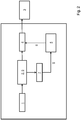
- Fig. 1 shows in a schematic representation a device known from the prior art.
- the device comprises a compressed air generator 1 and a pressure system 2. Compressed air can be applied to the pressure system 2 via the compressed air generator 1.
- an instrument 3 is connected to the pressure system 2 via a fluid line and a valve 4. To generate the required compressed air pulses, the valve 4 is controlled by a control device 5 Control signal 6 actuated, ie opened or closed.
- the instrument 3 can be designed as a vitrector, which uses the compressed air pulses to perform a cutting movement in order to remove tissue from an eye.
- control signal 6 i.e. Fixed values are stored for the switching pulses of the valve 4, so that a constant pressure is necessary for error-free operation of the device. If the compressed air generator 1 reaches its performance limit or if the system pressure fluctuates too high, malfunctions occur in the operation of the vitrector, up to and including a total failure.
- Fig. 2 shows in a schematic representation an embodiment of a device according to the invention, by means of which the control method according to the invention can be described.
- the device comprises a compressed air generator 1, which is operatively connected to a pressure system 2 so that pressure or compressed air can be applied to the pressure system 2.
- the pressure system 2 can be part of a compressed air circuit or form this and have a compressed air reservoir 9 and a valve 4 via which compressed air pulses can be generated with which the instrument 3 can be operated.
- a pressure sensor 7 is arranged with which the system pressure, here the pressure in the pressure system 2 or the compressed air reservoir 9, can be measured.
- the measured value 8 of the system pressure is transmitted to the control device 5 or can be called up by the latter.
- the control signal 6 for switching the valve 4 can thus be generated taking into account the measured system pressure. A dynamic calculation of the control signal 6 is thereby possible, whereby a trouble-free operation of an instrument 3 or vitrector is possible even when the system pressure fluctuates and operation above the performance limit is possible.
- the instrument 3 or the Vitrector is acted upon with a fixed pressure which is applied to the instrument 3 during the opening time of the valve 4, for example 2.4 bar.
- a fixed pressure which is applied to the instrument 3 during the opening time of the valve 4, for example 2.4 bar.
- the compressed air generator 1 or compressor has an air output of 12 liters per minute at a pressure of 2.4 bar, it follows from the fact that from a regulated compressed air circuit (with this compressed air generator 1) at 2.4 bar nominal pressure a maximum of 12 liters per minute of compressed air can be taken. This forms the performance limit of this compressed air generator 1.
- the system pressure falls below the nominal pressure, since the compressed air generator 1 can no longer apply the required pressure with this air consumption.
- the air consumption increases. If the air consumption is higher than the air output of the compressed air generator 1 at the nominal pressure, i. H. If operation is above the performance limit, the system pressure drops below the nominal pressure and the working point of the vitrector 3 shifts.
- the device according to the invention and the control method according to the invention make it possible to adapt the opening and closing times of the valve 4 to the shift in the operating point or to compensate for this.
- the control signal 6 can be called up from a lookup table by the control device 5 in a range of low and / or medium compressed air pulse rates or cutting rates.
- the control signal can be generated in the manner according to the invention, taking into account the measured value 8 of the system pressure.
- the generation of the control signal 6 is always determined taking into account the measured value 8, independently of the compressed air pulse rate.
Landscapes
- Health & Medical Sciences (AREA)
- Surgery (AREA)
- Life Sciences & Earth Sciences (AREA)
- Engineering & Computer Science (AREA)
- Ophthalmology & Optometry (AREA)
- Biomedical Technology (AREA)
- Heart & Thoracic Surgery (AREA)
- Vascular Medicine (AREA)
- Nuclear Medicine, Radiotherapy & Molecular Imaging (AREA)
- Animal Behavior & Ethology (AREA)
- General Health & Medical Sciences (AREA)
- Public Health (AREA)
- Veterinary Medicine (AREA)
- Medical Informatics (AREA)
- Molecular Biology (AREA)
- Control Of Fluid Pressure (AREA)
Description
- Die vorliegende Erfindung betrifft ein Steuerungsverfahren für eine Vorrichtung zur Bereitstellung von Druckluftimpulsen für ein ophthalmologisches Instrument, wobei ein Drucksystem über einen Druckluftgenerator mit Druck beaufschlagt wird und wobei ein Ventil des Drucksystems von einer Steuereinrichtung mittels eines Steuersignals betätigt wird, um die Druckluftimpulse zu erzeugen. Des Weiteren betrifft die Erfindung eine Vorrichtung zur Bereitstellung von Druckluftimpulsen für ein ophthalmologisches Instrument, mit einem Druckluftgenerator und einem Drucksystem, wobei das Drucksystem über den Druckluftgenerator mit Druckluft beaufschlagbar ist, wobei das Drucksystem ein Ventil aufweist und wobei das Ventil über ein von einer Steuereinrichtung erzeugtes Steuersignal betätigbar ist.
- Verfahren und Vorrichtungen zur Bereitstellung von Druckluftimpulsen sind seit Jahren aus der Praxis bekannt und dienen beispielsweise zum Betrieb von Vitrektoren bzw. Cuttern, die im Rahmen einer Vitrektomie zum Entfernen von Teilen des Glaskörpers verwendet werden. Beispielhaft wird hierzu auf die
DE 10 2008 019 790 A1 verwiesen. Darüber hinaus offenbartUS 2003 195 53 ein Verfahren, wobei, je nach Druckluftimpulsrate, die Impulsparameter geändert werden; ferner wird das die Steuerung des Ventils in Abhängigkeit des Messwertes des Systemdrucks bestimmt. - Bei den bekannten Vitrektoren wird die eigentliche Schneideinrichtung durch ein vom Griff oder vom Kopf des Instruments abragendes Außenrohr und ein im Außenrohr verschiebbar geführtes, pneumatisch betätigbares Innenrohr gebildet. Im vorderen Bereich des Außenrohrs ist eine seitliche Absaugöffnung vorgesehen, deren Innenkanten mit den vorderen freien Außenkanten des Innenrohres schneidend bzw. scherend zusammenwirken. Wird der Vitrektor mit Druckluft beaufschlagt, wird das Innenrohr in Richtung des distalen Endes des Außenrohrs gedrückt und dadurch ein Schnitt ausgeführt. Bei der Entlüftung des Überdrucks wird mittels einer mechanischen Feder das Innenrohr wieder in die Ausgangslage verbracht.
- Zur Auslenkung des Innenrohres werden Druckluftimpulse mit einer Frequenz von einigen Hertz bis hin zu einigen Kilohertz benötigt, wozu der Vitrektor über eine Leitung mit einer Vorrichtung zur Bereitstellung von Druckluftimpulsen verbunden ist. Eine solche Vorrichtung umfasst einen Druckluftgenerator, über den ein Drucksystem mit Druck beaufschlagbar ist. Das Drucksystem weist ein Ventil auf, so dass über eine Steuerung bzw. Schaltung des Ventils Druckluftimpulse erzeugbar sind, mit welchen das ophthalmologische Instrument betrieben wird. Das Steuersignal bzw. die Schaltimpulse des Ventils sind dabei für verschiedene Druckluftimpulsraten fest vorgegeben.
- Bei der bekannten Vorrichtung ist problematisch, dass ein nahezu konstanter Steuerdruck vorliegen muss, um einen fehlerfreien Betrieb des Vitrektors zu gewährleisten. Erreicht der Druckluftgenerator seine Leistungsgrenze oder weist der Systemdruck zu hohe Schwankungen auf, führt dies zu Störungen in der Funktion des Vitrektors, bis hin zu einem Totalausfall.
- Der vorliegenden Erfindung liegt daher die Aufgabe zugrunde, eine Vorrichtung der eingangs genannten Art sowie ein Steuerungsverfahren für eine solche Vorrichtung derart auszugestalten und weiterzubilden, dass eine sichere Funktion des ophthalmologischen Instruments auch bei schwankendem Systemdruck gewährleistet ist.
- Erfindungsgemäß wird die voranstehende Aufgabe durch die Merkmale des Anspruches 1 gelöst. Danach ist das Steuerungsverfahren für eine Vorrichtung zur Bereitstellung von Druckluftimpulsen für ein ophthalmologisches Instrument, wobei ein Drucksystem über einen Druckluftgenerator mit Druck beaufschlagt wird und wobei ein Ventil des Drucksystems von einer Steuereinrichtung mittels eines Steuersignals betätigt wird, um die Druckluftimpulse zu erzeugen, dadurch gekennzeichnet, dass mit einem Drucksensor der herrschende Systemdruck gemessen wird und dass zumindest für die Erzeugung von Druckluftimpulsraten eines bestimmten Wertebereichs das Steuersignal von der Steuereinrichtung unter Berücksichtigung des Messwertes des Systemdrucks erzeugt wird.
- In erfindungsgemäßer Weise ist zunächst erkannt worden, dass durch eine dynamische Ansteuerung des Ventils unter Berücksichtigung des herrschenden Systemdrucks die Funktion des Instruments auch bei schwankendem Systemdruck gewährleistet werden kann. Im Konkreten wird hierzu mit einem Drucksensor der Systemdruck bestimmt und zumindest bei bestimmten, insbesondere hohen, Druckluftimpulsraten zur Erzeugung des Steuersignals verwendet. Mit anderen Worten erfolgt die Erzeugung bzw. Berechnung des Steuersignals durch die Steuereinheit zumindest bereichsweise in Abhängigkeit des Systemdrucks. Es ist denkbar, dass die Bestimmung des Steuersignals unabhängig von der Druckluftimpulsrate stets unter Berücksichtigung des Messwertes des Systemdrucks erfolgen kann. Das Drucksystem kann Teil eines Druckluftkreises sein bzw. diesen bilden. Weiterhin kann das Drucksystem einen Druckluftspeicher aufweisen bzw. umfassen, der mittelbar oder unmittelbar durch den Druckluftgenerator mit Druckluft beaufschlagbar ist.
- Durch das erfindungsgemäße Steuerungsverfahren ist es möglich, Störungen des Drucksystems, bspw. eine Leckage, sowie Leistungstoleranzen der einzelnen Komponenten der Vorrichtung auszugleichen. Des Weiteren ist ein Betrieb der Vorrichtung oberhalb der Leistungsgrenze des Kompressors möglich. Handelt es sich bei dem mit Druckluftimpulsen zu betreibenden Instrument um einen Vitrektor, wird durch die Druckluftimpulsrate die Schneidrate des Vitrektors bestimmt.
- Der Begriff "Druckluft" ist nicht auf Umgebungsluft als Medium eingeschränkt. Vielmehr kann es sich dabei um ein beliebiges anderes Gas handeln.
- Unter "Systemdruck" ist der Druck zu verstehen, der in dem Drucksystem bzw. dem Druckluftspeicher und ggf. in weiteren Bauteilen der Vorrichtung herrscht.
- Bei der "Steuereinrichtung" kann es sich beispielsweise um einen Mikrokontroller oder eine andere geeignete Recheneinrichtung handeln.
- Für Druckluftimpulsraten von weniger als 500 Druckluftimpulsen pro Minute wird als Steuersignal ein fester Wert für die Öffnungszeit des Ventils und somit eine feste Impulsbreite vorgegeben.
- Für mittlere Druckluftimpulsraten bzw. Schneidraten des Instruments wird durch das Steuersignal ein festes Verhältnis zwischen Öffnungszeit und Schließzeit des Ventils vorgegeben werden. Dabei handelt es sich um Druckluftimpulsraten von 500 bis 1500 Druckluftimpulsen pro Minute. Gemäß einer besonders einfachen Ausgestaltung kann als Steuersignal ein fester Wert für das Verhältnis zwischen Öffnungszeit und Schließzeit des Ventils und somit ein fixer Duty-Cycle des Ventils vorgegeben sein. Für hohe Druckluftimpulsraten wird das Steuersignal von der Steuereinrichtung in Abhängigkeit des gemessenen Systemdrucks bestimmt. Hierbei handelt es sich um Druckluftimpulsraten von über 1500 Druckluftimpulsen pro Minute. Durch diese Maßnahme kann eine Korrektur des Verhältnisses zwischen der Öffnungszeit des Ventils und der Schließzeit des Ventils in Abhängigkeit von dem Systemdruck realisiert werden. Insbesondere ist denkbar, dass bei diesen hohen Druckluftimpulsraten das Verhältnis y zwischen Öffnungs- und Schließzeit des Ventils durch eine mathematische Funktion in Abhängigkeit des gemessenen Systemdrucks x berechnet wird, beispielsweise mittels der linearen Funktion y = - a•x +b, wobei a und b konstante Werte sind. Die Verwendung anderer mathematischer Funktionen ist möglich, beispielsweise einer Exponentialfunktion.
- Es wird ausdrücklich darauf hingewiesen, dass denkbar ist, dass die Erzeugung des Steuersignals unabhängig von der Druckluftimpulsrate stets unter Berücksichtigung des Messwertes des Systemdrucks erfolgen kann. Alternativ oder zusätzlich kann eine Optimierung des Duty-Cycle-Managements des Vitrektors und/oder des Laufverhaltens des Vitrektors durch verschiedene mathematische Berechnungsformeln, bspw. eine Exponentialkurve, erfolgen.
- Des Weiteren ist es von Vorteil, wenn die Druckluftimpulsrate über ein Eingabemittel veränderbar und/oder einstellbar ist. Somit kann von einem Operateur beispielsweise die Schneidrate des Instruments bzw. Vitrektors eingestellt werden bzw. ein Sollwert der Druckluftimpulsrate definiert werden.
- In besonders vorteilhafter Weise wird die Druckluftimpulsrate schrittweise angepasst, wenn der Betrag der Differenz zwischen Sollwert und Istwert der Druckluftimpulsrate einen definierten Wert überschreitet (Sollwertsprung). Durch diesen "Sanftanlauf" wird eine große Änderung der Druckluftimpulsrate, die beispielsweise durch den Operateur durch das Eingabemittel vorgegeben wird, nicht schlagartig vorgenommen, sondern verteilt über mehrere Druckluftimpulse angepasst. Dadurch wird das Laufverhalten des Instruments, beispielsweise des Vitrektors, bei Sollwertsprüngen erheblich verbessert.
- Um eine besonders einfache Konstruktion und zuverlässige Messung des Systemdrucks zu erreichen, ist es denkbar, dass der in dem Druckluftspeicher des Drucksystems herrschende Druck gemessen wird. Dadurch wird eine Verfälschung des Messwertes durch vom Betrieb des Druckluftgenerators und/oder des Ventils hervorgerufene Störsignale minimiert. Der hierzu verwendete Drucksensor kann in idealer Weise eine erhöhte Medienverträglichkeit aufweisen und robust sein, so dass Staub und Abrieb des Druckluftgenerators bzw. Kompressors sowie eine erhöhte Luftfeuchtigkeit bzw. Kondenswasser durch das Verdichten der Luft die Funktionsfähigkeit des Sensors nicht oder allenfalls vernachlässigbar beeinflussen.
- Die zugrunde liegende Aufgabe wird des Weiteren durch die Merkmale von Anspruch 9 gelöst. Danach ist eine Vorrichtung zur Bereitstellung von Druckluftimpulsen für ein ophthalmologisches Instrument, mit einem Druckluftgenerator und einem Drucksystem, wobei das Drucksystem über den Druckluftgenerator mit Druckluft beaufschlagbar ist, wobei das Drucksystem ein Ventil aufweist und wobei das Ventil über ein von einer Steuereinrichtung erzeugtes Steuersignal betätigbar ist, dadurch gekennzeichnet, dass ein Drucksensor zur Messung des herrschenden Systemdrucks angeordnet ist und dass der Messwert des Systemdrucks von der Steuereinrichtung abrufbar ist.
- In erfindungsgemäßer Weise ist erkannt worden, dass die zugrunde liegende Aufgabe durch eine Berücksichtigung des Systemdrucks zumindest bei der Erzeugung von bestimmten Druckluftimpulsraten auf verblüffend einfache Weise lösbar ist. Dazu weist die Vorrichtung einen Drucksensor auf, mittels welchem der Systemdruck bestimmbar ist. Der Systemdruck kann somit von der Steuereinrichtung bei der Erzeugung des Steuersignals zur Betätigung des Ventils berücksichtigt werden. Folglich ist der Begriff "abrufbar" dahingehend zu verstehen, dass der gemessene Wert des Systemdrucks der Steuereinrichtung zuführbar bzw. von dieser erfassbar ist, so dass unter Berücksichtigung des Systemdrucks die Steuerung des Ventils erfolgen kann.
- Um die Druckluftimpulsrate und somit die Schnittrate eines mit der Vorrichtung verbundenen Vitrektors einzustellen, kann ein Eingabemittel vorgesehen sein. Dabei kann es sich beispielsweise um ein Fußpedal bzw. Fußschalter, einen Touchscreen, eine Tastatur etc. handeln.
- In weiter vorteilhafter Weise erbringt der Druckluftgenerator eine Luftleistung von 12 Liter pro Minute bei einem Druck 2 bar bis 3 bar, insbesondere von 2,2 bar bis 2,8 bar, vorzugsweise von 2,4 bar.
- Es wird darauf hingewiesen, dass die zuvor erörterten Merkmale zu dem erfindungsgemäßen Steuerungsverfahren auch eine vorrichtungsgemäße Ausprägung haben können. Eine Kombination dieser Merkmale mit den den Vorrichtungsanspruch betreffenden Merkmalen ist nicht nur möglich, sondern von Vorteil und ausdrücklich Teil der Offenbarung. Das erfindungsgemäße Verfahren kann somit Merkmale der Ansprüche 1 bis 8, der entsprechenden Beschreibung sowie der nachstehenden Figurenbeschreibung aufweisen. Auch kann das erfindungsgemäße Steuerungsverfahren Merkmale der erfindungsgemäßen Vorrichtung aufweisen.
- Es gibt nun verschiedene Möglichkeiten, die Lehre der vorliegenden Erfindung in vorteilhafter Weise auszugestalten und weiterzubilden. Dazu ist einerseits auf die dem Anspruch 1 sowie dem Anspruch 9 nachgeordneten Ansprüche und andererseits auf die nachfolgende Erläuterung bevorzugter Ausführungsbeispiele der Erfindung anhand der Zeichnung zu verweisen. In Verbindung mit der Erläuterung der bevorzugten Ausführungsbeispiele der Erfindung anhand der Zeichnung werden auch im Allgemeinen bevorzugte Ausgestaltungen und Weiterbildungen der Lehre erläutert. In der Zeichnung zeigen
- Fig. 1
- in einer schematischen Darstellung eine aus dem Stand der Technik bekannte Vorrichtung zur Bereitstellung von Druckluftimpulsen für ein ophthalmologisches Instrument,
- Fig. 2
- in einer schematischen Darstellung eine erfindungsgemäße Vorrichtung, anhand der das erfindungsgemäße Steuerungsverfahren darstellbar ist.
-
Fig. 1 zeigt in einer schematischen Darstellung eine aus dem Stand der Technik bekannte Vorrichtung. Die Vorrichtung umfasst einen Druckluftgenerator 1 und ein Drucksystem 2. Über den Druckluftgenerator 1 ist das Drucksystem 2 mit Druckluft beaufschlagbar. Des Weiteren ist ein Instrument 3 über eine Fluidleitung und ein Ventil 4 mit dem Drucksystem 2 verbunden. Zur Erzeugung der benötigten Druckluftimpulse, wird das Ventil 4 über eine Steuereinrichtung 5 durch ein Steuersignal 6 betätigt, d.h. geöffnet bzw. geschlossen. Beispielsweise kann das Instrument 3 als Vitrektor ausgebildet sein, der durch die Druckluftimpulse eine Schneidbewegung ausführt, um Gewebe aus einem Auge zu entfernen. - Für das Steuersignal 6, d.h. für die Schaltimpulse des Ventils 4, sind feste Werte hinterlegt, so dass ein konstanter Druck für einen fehlerfreien Betrieb der Vorrichtung notwendig ist. Erlangt der Druckluftgenerator 1 seine Leistungsgrenze oder weist der Systemdruck zu hohe Schwankungen auf, treten Störungen im Betrieb des Vitrektors auf, bis hin zu einem Totalausfall.
-
Fig. 2 zeigt in einer schematischen Darstellung ein Ausführungsbeispiel einer erfindungsgemäßen Vorrichtung, anhand der das erfindungsgemäße Steuerungsverfahren beschreibbar ist. - Die Vorrichtung umfasst einen Druckluftgenerator 1, der mit einem Drucksystem 2 wirkverbunden ist, so dass das Drucksystem 2 mit Druck bzw. Druckluft beaufschlagbar ist. Das Drucksystem 2 kann Teil eines Druckluftkreises sein bzw. diesen bilden und einen Druckluftspeicher 9 sowie ein Ventil 4 aufweisen, über das Druckluftimpulse erzeugbar sind, mit welchen das Instrument 3 betreibbar ist.
- Aus
Fig. 2 geht des Weiteren hervor, dass ein Drucksensor 7 angeordnet ist, mit dem der Systemdruck, hier der Druck in dem Drucksystem 2 bzw. dem Druckluftspeicher 9, messbar ist. Der Messwert 8 des Systemdrucks wird an die Steuereinrichtung 5 übermittelt bzw. ist von dieser abrufbar. Somit kann die Erzeugung des Steuersignals 6 zur Schaltung des Ventils 4 unter Berücksichtigung des gemessenen Systemdrucks erfolgen. Hierdurch ist eine dynamische Berechnung des Steuersignals 6 möglich, wodurch ein störungsfreier Betrieb eines Instruments 3 bzw. Vitrektors auch bei schwankendem Systemdruck sowie ein Betrieb oberhalb der Leistungsgrenze möglich ist. - Idealer Weise wird das Instrument 3 bzw. der Vitrektor mit einem festen Druck beaufschlagt, der während der Öffnungszeit des Ventils 4 an dem Instrument 3 anliegt, beispielsweise 2,4 bar. Weist der Druckluftgenerator 1 bzw. Kompressor eine Luftleistung von 12 Liter pro Minute bei einem Druck von 2,4 bar auf, so folgt daraus, dass aus einem geregelten Druckluftkreis (mit diesem Druckluftgenerator 1) bei 2,4 bar Nenndruck höchstens 12 Liter pro Minute an Druckluft entnommen werden kann. Dies bildet die Leistungsgrenze dieses Druckluftgenerators 1. Sobald mehr Luft entnommen wird, fällt der Systemdruck unter den Nenndruck, da der Druckluftgenerator 1 bei diesem Luftverbrauch den geforderten Druck nicht mehr aufbringen kann.
- Mit zunehmender Druckluftimpulsrate bzw. Schneidrate des Vitrektors 3 nimmt der Luftverbrauch zu. Ist der Luftverbrauch höher als die Luftleistung des Druckluftgenerators 1 bei Nenndruck, d. h. besteht ein Betrieb oberhalb der Leistungsgrenze, sinkt der Systemdruck unter der Nenndruck ab und der Arbeitspunkt des Vitrektors 3 verschiebt sich. Durch die erfindungsgemäße Vorrichtung und das erfindungsgemäße Steuerungsverfahren ist es möglich, die Öffnungs- und Schließzeiten des Ventils 4 an die Verschiebung des Arbeitspunktes anzupassen bzw. diese auszugleichen.
- Beispielsweise kann bei dem erfindungsgemäßen Steuerungsverfahren in einem Bereich geringer und/oder mittlerer Druckluftimpulsraten bzw. Schneidraten das Steuersignal 6 aus einer Lookup-Tabelle von der Steuereinrichtung 5 abgerufen werden. Bei hohen Druckluftimpulsraten und somit Schneidraten des Vitrektors 3 kann die Erzeugung des Steuersignals in erfindungsgemäßer Weise unter Berücksichtigung des Messwertes 8 des Systemdrucks erfolgen. Des Weiteren ist denkbar, dass die Erzeugung des Steuersignals 6 unabhängig von der Druckluftimpulsrate stets unter Berücksichtigung des Messwertes 8 ermittelt wird.
- Hinsichtlich weiterer vorteilhafter Ausgestaltungen der erfindungsgemäßen Vorrichtung wird zur Vermeidung von Wiederholungen auf den allgemeinen Teil der Beschreibung sowie auf die beigefügten Ansprüche verwiesen.
- Schließlich sei ausdrücklich darauf hingewiesen, dass die voranstehend beschriebenen Ausführungsbeispiele der erfindungsgemäßen Vorrichtung lediglich zur Erörterung der beanspruchten Lehre dienen, diese jedoch nicht auf die Ausführungsbeispiele einschränken. Die Erfindung wird in den Ansprüchen definiert; andere Ausführungsformen sind lediglich für illustrative Zwecke offenbart.
-
- 1
- Druckluftgenerator
- 2
- Drucksystem
- 3
- Instrument
- 4
- Ventil
- 5
- Steuereinrichtung
- 6
- Steuersignal
- 7
- Drucksensor
- 8
- Messwert (Systemdruck)
- 9
- Druckluftspeicher
Claims (8)
- Steuerungsverfahren für eine Vorrichtung zur Bereitstellung von Druckluftimpulsen für ein ophthalmologisches Instrument (3), wobei ein Drucksystem (2) über einen Druckluftgenerator (1) mit Druck beaufschlagt wird und wobei ein Ventil (4) des Drucksystems (2) von einer Steuereinrichtung (5) mittels eines Steuersignals (6) betätigt wird, um die Druckluftimpulse zu erzeugen, wobei mit einem Drucksensor (7) der herrschende Systemdruck gemessen wird und dass zumindest für die Erzeugung von Druckluftimpulsraten eines bestimmten Wertebereichs das Steuersignal (6) von der Steuereinrichtung (5) unter Berücksichtigung des Messwertes (8) des Systemdrucks erzeugt wird,
dadurch gekennzeichnet, dass für geringe Druckluftimpulsraten von weniger als 500 Druckluftimpulsen pro Minute, das Steuersignal (6) eine Öffnungszeit des Ventils (4) vorgibt,
dass für mittlere Druckluftimpulsraten von 500 und 1500 Druckluftimpulsen pro Minute das Steuersignal (6) ein festes Verhältnis zwischen der Öffnungszeit und der Schließzeit des Ventils (4) vorgibt und
dass für hohe Druckluftimpulsraten von über 1500 Druckluftimpulsen pro Minute, das Steuersignal (6) von der Steuereinrichtung (5) in Abhängigkeit des Messwertes (8) des Systemdrucks bestimmt wird. - Steuerungsverfahren nach Anspruch 1, dadurch gekennzeichnet, dass, bei hohen Druckluftimpulsraten, das Verhältnis zwischen Öffnungs- und Schließzeit des Ventils (4) durch eine mathematische Funktion in Abhängigkeit des Messwertes (8) berechnet wird.
- Steuerungsverfahren nach Anspruch 1 oder 2, dadurch gekennzeichnet, dass ein Sollwert der Druckluftimpulsrate über ein Eingabemittel veränderbar und/oder einstellbar ist.
- Steuerungsverfahren nach dem Anspruch 3, dadurch gekennzeichnet, dass die Druckluftimpulsrate schrittweise angepasst wird, wenn der Betrag der Differenz zwischen Sollwert und Istwert der Druckluftimpulsrate einen definierten Wert überschreitet.
- Steuerungsverfahren nach einem der Ansprüche 1 bis 4, dadurch gekennzeichnet, dass zur Bestimmung des Systemdrucks der in dem Drucksystem (2) herrschende Druck gemessen wird.
- Vorrichtung zur Bereitstellung von Druckluftimpulsen für ein ophthalmologisches Instrument (3), mit einem Druckluftgenerator (1) und einem Drucksystem (2), wobei das Drucksystem (2) über den Druckluftgenerator (1) mit Druckluft beaufschlagbar ist, wobei das Drucksystem (2) ein Ventil (4) aufweist und wobei das Ventil (4) über ein von einer Steuereinrichtung (5) erzeugtes Steuersignal (6) betätigbar ist,
dadurch gekennzeichnet, dass ein Drucksensor (7) zur Messung des herrschenden Systemdrucks angeordnet ist und dass der Messwert (8) des Systemdrucks von der Steuereinrichtung (5) abrufbar ist, wobei für geringe Druckluftimpulsraten von weniger als 500 Druckluftimpulsen pro Minute, über das Steuersignal (6) eine Öffnungszeit des Ventils (4) vorgebbar ist,
dass für mittlere Druckluftimpulsraten von 500 und 1500 Druckluftimpulsen pro Minute das Steuersignal (6) ein festes Verhältnis zwischen der Öffnungszeit und der Schließzeit des Ventils (4) vergebbar ist und
dass für hohe Druckluftimpulsraten von über 1500 Druckluftimpulsen pro Minute, das Steuersignal (6) von der Steuereinrichtung (5) in Abhängigkeit des Messwertes (8) des Systemdrucks bestimmbar ist. - Vorrichtung nach Anspruch 6, dadurch gekennzeichnet, dass ein Eingabemittel angeordnet ist, um eine Druckluftimpulsrate einzustellen.
- Vorrichtung nach Anspruch 6 oder 7, dadurch gekennzeichnet, dass der Druckluftgenerator (1) eine Luftleistung von 12 Liter pro Minute bei einem Druck 2 bar bis 3 bar, insbesondere von 2,2 bar bis 2,8 bar, vorzugsweise von 2,4 bar, erbringt.
Applications Claiming Priority (2)
| Application Number | Priority Date | Filing Date | Title |
|---|---|---|---|
| DE102017208584.3A DE102017208584A1 (de) | 2017-05-22 | 2017-05-22 | Vorrichtung zur Bereitstellung von Druckluftimpulsen für ein ophthalmologisches Instrument und ein Steuerungsverfahren für solch eine Vorrichtung |
| PCT/DE2018/200051 WO2018215032A1 (de) | 2017-05-22 | 2018-05-18 | Vorrichtung zur bereitstellung von druckluftimpulsen für ein ophthalmologisches instrument und ein steuerungsverfahren für solch eine vorrichtung |
Publications (2)
| Publication Number | Publication Date |
|---|---|
| EP3478231A1 EP3478231A1 (de) | 2019-05-08 |
| EP3478231B1 true EP3478231B1 (de) | 2020-08-12 |
Family
ID=62750726
Family Applications (1)
| Application Number | Title | Priority Date | Filing Date |
|---|---|---|---|
| EP18734422.1A Active EP3478231B1 (de) | 2017-05-22 | 2018-05-18 | Vorrichtung zur bereitstellung von druckluftimpulsen für ein ophthalmologisches instrument und ein steuerungsverfahren für solch eine vorrichtung |
Country Status (3)
| Country | Link |
|---|---|
| EP (1) | EP3478231B1 (de) |
| DE (1) | DE102017208584A1 (de) |
| WO (1) | WO2018215032A1 (de) |
Families Citing this family (1)
| Publication number | Priority date | Publication date | Assignee | Title |
|---|---|---|---|---|
| DE102022112103B4 (de) * | 2022-05-13 | 2024-01-04 | Carl Zeiss Meditec Ag | Konsole eines ophthalmochirurgischen Systems sowie ophthalmochirurgisches System zur Behandlung eines Auges |
Family Cites Families (5)
| Publication number | Priority date | Publication date | Assignee | Title |
|---|---|---|---|---|
| US6575990B1 (en) * | 1999-10-21 | 2003-06-10 | Medical Instrument Development Laboratories, Inc. | High speed vitreous cutting system |
| DE102008019790A1 (de) | 2008-04-18 | 2009-10-22 | Geuder Ag | Medizinisches Handgerät |
| US8821524B2 (en) * | 2010-05-27 | 2014-09-02 | Alcon Research, Ltd. | Feedback control of on/off pneumatic actuators |
| US9498376B2 (en) * | 2012-12-17 | 2016-11-22 | Abbott Medical Optics Inc. | Vitrectomy surgical apparatus with cut timing based on pressures encountered |
| CA2946723A1 (en) * | 2014-04-23 | 2015-10-29 | Abbott Medical Optics Inc. | Vitrectomy surgical apparatus employing multisensor pressure feedback |
-
2017
- 2017-05-22 DE DE102017208584.3A patent/DE102017208584A1/de not_active Withdrawn
-
2018
- 2018-05-18 WO PCT/DE2018/200051 patent/WO2018215032A1/de not_active Ceased
- 2018-05-18 EP EP18734422.1A patent/EP3478231B1/de active Active
Non-Patent Citations (1)
| Title |
|---|
| None * |
Also Published As
| Publication number | Publication date |
|---|---|
| DE102017208584A1 (de) | 2018-11-22 |
| EP3478231A1 (de) | 2019-05-08 |
| WO2018215032A1 (de) | 2018-11-29 |
Similar Documents
| Publication | Publication Date | Title |
|---|---|---|
| EP3455111B1 (de) | Automatisiert kalibrierbares bremssystem und verfahren zum automatisierten kalibrieren eines bremssystems | |
| EP1915650B1 (de) | Regelungsverfahren und regler für ein mechanisch-hydraulisches system | |
| WO2019228697A1 (de) | Beatmungsgerät und verfahren zum betrieb eines beatmungsgeräts | |
| DE3723284A1 (de) | Automatisches druckreduzierventil | |
| DE102014219536B4 (de) | Verfahren zur Ermittlung einer Betätigungskraft eines Stellaktuators sowie Betätigungseinrichtung mit einem Stellaktuator | |
| DE102014206878B4 (de) | Verfahren zum Steuern der Atemgaszufuhr | |
| DE3000218C2 (de) | Apparat zum Insufflieren von strömungsfähigen Medien | |
| DE102017130873A1 (de) | Vorrichtung und Verfahren zur Überwachung eines Keiltriebwerkzeugs | |
| EP2304515B1 (de) | Steueranordnung mit einem druckbegrenzungsventil | |
| EP2258952B1 (de) | Pneumatischer Stellungsregler mit piezopneumatischer Ventileinheit | |
| WO2018215032A1 (de) | Vorrichtung zur bereitstellung von druckluftimpulsen für ein ophthalmologisches instrument und ein steuerungsverfahren für solch eine vorrichtung | |
| DE1803179A1 (de) | Einrichtung zum Regeln der seitlichen Lage einer laufenden Materialbahn | |
| DE102016214708A1 (de) | Stetigventileinheit, hydraulische Achse und Verfahren zum Betreiben einer hydraulischen Achse | |
| EP3880089B1 (de) | Druckwellengerät zur behandlung eines menschlichen oder tierischen körpers | |
| EP2540334B1 (de) | Beatmungssystem | |
| EP3857074A1 (de) | Verfahren zum prüfen der funktionsfähigkeit eines magnetventils zum auslösen eines sicherheitsventils | |
| DE102017223242B4 (de) | Steuervorrichtung, System und Verfahren zum Einstellen eines Werts einer Betriebsgröße | |
| DE102023122643A1 (de) | Verfahren zur Bestimmung eines Korrekturwertes für eine Regeleinrichtung für ein Regelventil | |
| DE102014219710A1 (de) | Verfahren zur Steuerung eines Linearantriebs und Linearantriebsaggregat | |
| DE3820043A1 (de) | Atemhilfegeraet | |
| DE102009057029B4 (de) | Druckregelvorrichtung | |
| DE102021115279B3 (de) | Verfahren und System zur Diagnose von zuluftseitigen Druckschwankungen und/oder ausgangsseitigen Leckagen bei einem geregelten Doppelkegel-Luftleistungsverstärker | |
| EP1475119B1 (de) | Vorrichtung zur Steuerung einer Gasströmung | |
| DE102022122028A1 (de) | Gasmischvorrichtung zum kontrollierten Mischen von zwei unterschiedlichen Gasen | |
| DE10150101B4 (de) | Presse und Verfahren zum Umformen von Werkstücken |
Legal Events
| Date | Code | Title | Description |
|---|---|---|---|
| STAA | Information on the status of an ep patent application or granted ep patent |
Free format text: STATUS: UNKNOWN |
|
| STAA | Information on the status of an ep patent application or granted ep patent |
Free format text: STATUS: THE INTERNATIONAL PUBLICATION HAS BEEN MADE |
|
| PUAI | Public reference made under article 153(3) epc to a published international application that has entered the european phase |
Free format text: ORIGINAL CODE: 0009012 |
|
| STAA | Information on the status of an ep patent application or granted ep patent |
Free format text: STATUS: REQUEST FOR EXAMINATION WAS MADE |
|
| 17P | Request for examination filed |
Effective date: 20190130 |
|
| AK | Designated contracting states |
Kind code of ref document: A1 Designated state(s): AL AT BE BG CH CY CZ DE DK EE ES FI FR GB GR HR HU IE IS IT LI LT LU LV MC MK MT NL NO PL PT RO RS SE SI SK SM TR |
|
| AX | Request for extension of the european patent |
Extension state: BA ME |
|
| GRAP | Despatch of communication of intention to grant a patent |
Free format text: ORIGINAL CODE: EPIDOSNIGR1 |
|
| STAA | Information on the status of an ep patent application or granted ep patent |
Free format text: STATUS: GRANT OF PATENT IS INTENDED |
|
| DAV | Request for validation of the european patent (deleted) | ||
| DAX | Request for extension of the european patent (deleted) | ||
| INTG | Intention to grant announced |
Effective date: 20200325 |
|
| GRAS | Grant fee paid |
Free format text: ORIGINAL CODE: EPIDOSNIGR3 |
|
| GRAA | (expected) grant |
Free format text: ORIGINAL CODE: 0009210 |
|
| STAA | Information on the status of an ep patent application or granted ep patent |
Free format text: STATUS: THE PATENT HAS BEEN GRANTED |
|
| AK | Designated contracting states |
Kind code of ref document: B1 Designated state(s): AL AT BE BG CH CY CZ DE DK EE ES FI FR GB GR HR HU IE IS IT LI LT LU LV MC MK MT NL NO PL PT RO RS SE SI SK SM TR |
|
| REG | Reference to a national code |
Ref country code: CH Ref legal event code: EP |
|
| REG | Reference to a national code |
Ref country code: DE Ref legal event code: R096 Ref document number: 502018002187 Country of ref document: DE |
|
| REG | Reference to a national code |
Ref country code: IE Ref legal event code: FG4D Free format text: LANGUAGE OF EP DOCUMENT: GERMAN |
|
| REG | Reference to a national code |
Ref country code: AT Ref legal event code: REF Ref document number: 1300793 Country of ref document: AT Kind code of ref document: T Effective date: 20200915 |
|
| REG | Reference to a national code |
Ref country code: NL Ref legal event code: FP |
|
| REG | Reference to a national code |
Ref country code: LT Ref legal event code: MG4D |
|
| PG25 | Lapsed in a contracting state [announced via postgrant information from national office to epo] |
Ref country code: GR Free format text: LAPSE BECAUSE OF FAILURE TO SUBMIT A TRANSLATION OF THE DESCRIPTION OR TO PAY THE FEE WITHIN THE PRESCRIBED TIME-LIMIT Effective date: 20201113 Ref country code: BG Free format text: LAPSE BECAUSE OF FAILURE TO SUBMIT A TRANSLATION OF THE DESCRIPTION OR TO PAY THE FEE WITHIN THE PRESCRIBED TIME-LIMIT Effective date: 20201112 Ref country code: NO Free format text: LAPSE BECAUSE OF FAILURE TO SUBMIT A TRANSLATION OF THE DESCRIPTION OR TO PAY THE FEE WITHIN THE PRESCRIBED TIME-LIMIT Effective date: 20201112 Ref country code: HR Free format text: LAPSE BECAUSE OF FAILURE TO SUBMIT A TRANSLATION OF THE DESCRIPTION OR TO PAY THE FEE WITHIN THE PRESCRIBED TIME-LIMIT Effective date: 20200812 Ref country code: LT Free format text: LAPSE BECAUSE OF FAILURE TO SUBMIT A TRANSLATION OF THE DESCRIPTION OR TO PAY THE FEE WITHIN THE PRESCRIBED TIME-LIMIT Effective date: 20200812 Ref country code: FI Free format text: LAPSE BECAUSE OF FAILURE TO SUBMIT A TRANSLATION OF THE DESCRIPTION OR TO PAY THE FEE WITHIN THE PRESCRIBED TIME-LIMIT Effective date: 20200812 Ref country code: SE Free format text: LAPSE BECAUSE OF FAILURE TO SUBMIT A TRANSLATION OF THE DESCRIPTION OR TO PAY THE FEE WITHIN THE PRESCRIBED TIME-LIMIT Effective date: 20200812 |
|
| PG25 | Lapsed in a contracting state [announced via postgrant information from national office to epo] |
Ref country code: LV Free format text: LAPSE BECAUSE OF FAILURE TO SUBMIT A TRANSLATION OF THE DESCRIPTION OR TO PAY THE FEE WITHIN THE PRESCRIBED TIME-LIMIT Effective date: 20200812 Ref country code: PL Free format text: LAPSE BECAUSE OF FAILURE TO SUBMIT A TRANSLATION OF THE DESCRIPTION OR TO PAY THE FEE WITHIN THE PRESCRIBED TIME-LIMIT Effective date: 20200812 Ref country code: RS Free format text: LAPSE BECAUSE OF FAILURE TO SUBMIT A TRANSLATION OF THE DESCRIPTION OR TO PAY THE FEE WITHIN THE PRESCRIBED TIME-LIMIT Effective date: 20200812 Ref country code: IS Free format text: LAPSE BECAUSE OF FAILURE TO SUBMIT A TRANSLATION OF THE DESCRIPTION OR TO PAY THE FEE WITHIN THE PRESCRIBED TIME-LIMIT Effective date: 20201212 |
|
| PG25 | Lapsed in a contracting state [announced via postgrant information from national office to epo] |
Ref country code: RO Free format text: LAPSE BECAUSE OF FAILURE TO SUBMIT A TRANSLATION OF THE DESCRIPTION OR TO PAY THE FEE WITHIN THE PRESCRIBED TIME-LIMIT Effective date: 20200812 Ref country code: DK Free format text: LAPSE BECAUSE OF FAILURE TO SUBMIT A TRANSLATION OF THE DESCRIPTION OR TO PAY THE FEE WITHIN THE PRESCRIBED TIME-LIMIT Effective date: 20200812 Ref country code: CZ Free format text: LAPSE BECAUSE OF FAILURE TO SUBMIT A TRANSLATION OF THE DESCRIPTION OR TO PAY THE FEE WITHIN THE PRESCRIBED TIME-LIMIT Effective date: 20200812 Ref country code: EE Free format text: LAPSE BECAUSE OF FAILURE TO SUBMIT A TRANSLATION OF THE DESCRIPTION OR TO PAY THE FEE WITHIN THE PRESCRIBED TIME-LIMIT Effective date: 20200812 Ref country code: SM Free format text: LAPSE BECAUSE OF FAILURE TO SUBMIT A TRANSLATION OF THE DESCRIPTION OR TO PAY THE FEE WITHIN THE PRESCRIBED TIME-LIMIT Effective date: 20200812 |
|
| REG | Reference to a national code |
Ref country code: DE Ref legal event code: R097 Ref document number: 502018002187 Country of ref document: DE |
|
| PG25 | Lapsed in a contracting state [announced via postgrant information from national office to epo] |
Ref country code: AL Free format text: LAPSE BECAUSE OF FAILURE TO SUBMIT A TRANSLATION OF THE DESCRIPTION OR TO PAY THE FEE WITHIN THE PRESCRIBED TIME-LIMIT Effective date: 20200812 Ref country code: ES Free format text: LAPSE BECAUSE OF FAILURE TO SUBMIT A TRANSLATION OF THE DESCRIPTION OR TO PAY THE FEE WITHIN THE PRESCRIBED TIME-LIMIT Effective date: 20200812 |
|
| PLBE | No opposition filed within time limit |
Free format text: ORIGINAL CODE: 0009261 |
|
| STAA | Information on the status of an ep patent application or granted ep patent |
Free format text: STATUS: NO OPPOSITION FILED WITHIN TIME LIMIT |
|
| PG25 | Lapsed in a contracting state [announced via postgrant information from national office to epo] |
Ref country code: SK Free format text: LAPSE BECAUSE OF FAILURE TO SUBMIT A TRANSLATION OF THE DESCRIPTION OR TO PAY THE FEE WITHIN THE PRESCRIBED TIME-LIMIT Effective date: 20200812 |
|
| 26N | No opposition filed |
Effective date: 20210514 |
|
| PG25 | Lapsed in a contracting state [announced via postgrant information from national office to epo] |
Ref country code: SI Free format text: LAPSE BECAUSE OF FAILURE TO SUBMIT A TRANSLATION OF THE DESCRIPTION OR TO PAY THE FEE WITHIN THE PRESCRIBED TIME-LIMIT Effective date: 20200812 |
|
| PG25 | Lapsed in a contracting state [announced via postgrant information from national office to epo] |
Ref country code: MC Free format text: LAPSE BECAUSE OF FAILURE TO SUBMIT A TRANSLATION OF THE DESCRIPTION OR TO PAY THE FEE WITHIN THE PRESCRIBED TIME-LIMIT Effective date: 20200812 Ref country code: LU Free format text: LAPSE BECAUSE OF NON-PAYMENT OF DUE FEES Effective date: 20210518 |
|
| REG | Reference to a national code |
Ref country code: BE Ref legal event code: MM Effective date: 20210531 |
|
| PG25 | Lapsed in a contracting state [announced via postgrant information from national office to epo] |
Ref country code: IE Free format text: LAPSE BECAUSE OF NON-PAYMENT OF DUE FEES Effective date: 20210518 |
|
| PG25 | Lapsed in a contracting state [announced via postgrant information from national office to epo] |
Ref country code: BE Free format text: LAPSE BECAUSE OF NON-PAYMENT OF DUE FEES Effective date: 20210531 |
|
| PGFP | Annual fee paid to national office [announced via postgrant information from national office to epo] |
Ref country code: IT Payment date: 20220531 Year of fee payment: 5 Ref country code: FR Payment date: 20220530 Year of fee payment: 5 |
|
| PG25 | Lapsed in a contracting state [announced via postgrant information from national office to epo] |
Ref country code: PT Free format text: LAPSE BECAUSE OF FAILURE TO SUBMIT A TRANSLATION OF THE DESCRIPTION OR TO PAY THE FEE WITHIN THE PRESCRIBED TIME-LIMIT Effective date: 20201214 |
|
| PG25 | Lapsed in a contracting state [announced via postgrant information from national office to epo] |
Ref country code: CY Free format text: LAPSE BECAUSE OF FAILURE TO SUBMIT A TRANSLATION OF THE DESCRIPTION OR TO PAY THE FEE WITHIN THE PRESCRIBED TIME-LIMIT Effective date: 20200812 |
|
| P01 | Opt-out of the competence of the unified patent court (upc) registered |
Effective date: 20230525 |
|
| PG25 | Lapsed in a contracting state [announced via postgrant information from national office to epo] |
Ref country code: HU Free format text: LAPSE BECAUSE OF FAILURE TO SUBMIT A TRANSLATION OF THE DESCRIPTION OR TO PAY THE FEE WITHIN THE PRESCRIBED TIME-LIMIT; INVALID AB INITIO Effective date: 20180518 |
|
| PG25 | Lapsed in a contracting state [announced via postgrant information from national office to epo] |
Ref country code: MK Free format text: LAPSE BECAUSE OF FAILURE TO SUBMIT A TRANSLATION OF THE DESCRIPTION OR TO PAY THE FEE WITHIN THE PRESCRIBED TIME-LIMIT Effective date: 20200812 Ref country code: IT Free format text: LAPSE BECAUSE OF NON-PAYMENT OF DUE FEES Effective date: 20230518 |
|
| PG25 | Lapsed in a contracting state [announced via postgrant information from national office to epo] |
Ref country code: FR Free format text: LAPSE BECAUSE OF NON-PAYMENT OF DUE FEES Effective date: 20230531 |
|
| REG | Reference to a national code |
Ref country code: AT Ref legal event code: MM01 Ref document number: 1300793 Country of ref document: AT Kind code of ref document: T Effective date: 20230518 |
|
| PG25 | Lapsed in a contracting state [announced via postgrant information from national office to epo] |
Ref country code: AT Free format text: LAPSE BECAUSE OF NON-PAYMENT OF DUE FEES Effective date: 20230518 |
|
| PG25 | Lapsed in a contracting state [announced via postgrant information from national office to epo] |
Ref country code: AT Free format text: LAPSE BECAUSE OF NON-PAYMENT OF DUE FEES Effective date: 20230518 |
|
| PG25 | Lapsed in a contracting state [announced via postgrant information from national office to epo] |
Ref country code: MT Free format text: LAPSE BECAUSE OF FAILURE TO SUBMIT A TRANSLATION OF THE DESCRIPTION OR TO PAY THE FEE WITHIN THE PRESCRIBED TIME-LIMIT Effective date: 20200812 |
|
| PGFP | Annual fee paid to national office [announced via postgrant information from national office to epo] |
Ref country code: NL Payment date: 20250522 Year of fee payment: 8 |
|
| PGFP | Annual fee paid to national office [announced via postgrant information from national office to epo] |
Ref country code: GB Payment date: 20250522 Year of fee payment: 8 |
|
| PGFP | Annual fee paid to national office [announced via postgrant information from national office to epo] |
Ref country code: CH Payment date: 20250601 Year of fee payment: 8 |
|
| PGFP | Annual fee paid to national office [announced via postgrant information from national office to epo] |
Ref country code: DE Payment date: 20250730 Year of fee payment: 8 |
|
| PG25 | Lapsed in a contracting state [announced via postgrant information from national office to epo] |
Ref country code: TR Free format text: LAPSE BECAUSE OF FAILURE TO SUBMIT A TRANSLATION OF THE DESCRIPTION OR TO PAY THE FEE WITHIN THE PRESCRIBED TIME-LIMIT Effective date: 20200812 |
|
| PGFP | Annual fee paid to national office [announced via postgrant information from national office to epo] |
Ref country code: AT Payment date: 20260410 Year of fee payment: 5 |