EP3477847A1 - Machine asynchrone à double alimentation ainsi que procédé de fonctionnement d'une machine asynchrone à double alimentation - Google Patents
Machine asynchrone à double alimentation ainsi que procédé de fonctionnement d'une machine asynchrone à double alimentation Download PDFInfo
- Publication number
- EP3477847A1 EP3477847A1 EP17198315.8A EP17198315A EP3477847A1 EP 3477847 A1 EP3477847 A1 EP 3477847A1 EP 17198315 A EP17198315 A EP 17198315A EP 3477847 A1 EP3477847 A1 EP 3477847A1
- Authority
- EP
- European Patent Office
- Prior art keywords
- asynchronous machine
- stator
- excitation
- rotor
- unit
- Prior art date
- Legal status (The legal status is an assumption and is not a legal conclusion. Google has not performed a legal analysis and makes no representation as to the accuracy of the status listed.)
- Withdrawn
Links
Images


Classifications
-
- H—ELECTRICITY
- H02—GENERATION; CONVERSION OR DISTRIBUTION OF ELECTRIC POWER
- H02P—CONTROL OR REGULATION OF ELECTRIC MOTORS, ELECTRIC GENERATORS OR DYNAMO-ELECTRIC CONVERTERS; CONTROLLING TRANSFORMERS, REACTORS OR CHOKE COILS
- H02P9/00—Arrangements for controlling electric generators for the purpose of obtaining a desired output
- H02P9/007—Control circuits for doubly fed generators
-
- H—ELECTRICITY
- H02—GENERATION; CONVERSION OR DISTRIBUTION OF ELECTRIC POWER
- H02P—CONTROL OR REGULATION OF ELECTRIC MOTORS, ELECTRIC GENERATORS OR DYNAMO-ELECTRIC CONVERTERS; CONTROLLING TRANSFORMERS, REACTORS OR CHOKE COILS
- H02P1/00—Arrangements for starting electric motors or dynamo-electric converters
- H02P1/16—Arrangements for starting electric motors or dynamo-electric converters for starting dynamo-electric motors or dynamo-electric converters
- H02P1/26—Arrangements for starting electric motors or dynamo-electric converters for starting dynamo-electric motors or dynamo-electric converters for starting an individual polyphase induction motor
Definitions
- the invention relates to a double-fed asynchronous machine with a rotor having a field winding for exciting the asynchronous machine, as well as with a control unit for controlling the excitation unit.
- a second aspect of the invention relates to a method of operating a double-fed asynchronous machine.
- a double-fed asynchronous machine has a stator and a rotor.
- the stator comprises a winding arrangement, which in an operation of the asynchronous machine is preferably connected to a power grid, for example the 50 Hz interconnected grid.
- the rotor has an excitation winding, which is connected to a power converter, in particular a converter. About the inverter, the excitation winding can be indirectly connected to the power grid.
- electrical power can be fed from the network into the rotor or from the rotor into the network via the power converter.
- the speed of the rotor may be below the synchronous speed (under-synchronous operation) or above the synchronous speed (over-synchronous operation).
- an electrical power absorbed or emitted by the stator is regulated via the excitation of the asynchronous machine or of the rotor.
- an electrical voltage is applied to the field winding via the power converter and / or an electrical current is impressed into the field winding.
- the power converter has for this purpose a control unit, which speed and angle of the rotor via a rotary encoder and amplitude and phase of the voltage and / or the current in the winding assembly via electrical transducers.
- the excitation of the rotor is regulated as a function of the rotational speed and angle of the rotor as well as dependent on the amplitude and phase position of the voltage and / or the current in the winding arrangement.
- encoderless control method are known in which the angle of the rotor on the amplitudes and phase angles of the currents and voltages in the stator and the rotor is determined. In summary, it is always a closed loop for controlling the rotor voltage of the rotor current.
- a disadvantage of the prior art is that the power converter, in particular the inverter, must be designed specifically for the asynchronous machine.
- the invention provides that the control unit has no signaling or electrical connection to the stator, which goes beyond a pure power supply of the control unit, so that the at least one electrical variable regardless of electrical stator sizes of the winding assembly is adjustable by the control unit.
- the exciter unit is a current source or a voltage source.
- the winding arrangement of the stator is designed in particular three-phase. In an operation of the asynchronous machine, a three-phase current then flows through the winding arrangement as a stator current.
- the stator current refers to the total current flowing through the winding assembly.
- a stator voltage a voltage is referred to, which rests on the winding assembly. This is in particular a three-phase AC voltage.
- the stator voltage, the stator current and their phase position, for example to each other and / or with respect to a power grid, are examples of stator sizes.
- the excitation winding is designed in particular three-phase. Accordingly, the excitation unit can be set up to impress a current flow (rotor current) into the excitation winding and / or to apply a voltage (rotor voltage) to the exciter winding. As a result, the excitation of the asynchronous machine can be achieved. Depending on the operating point of the asynchronous machine, the exciter unit can be designed to feed electrical power into the exciter winding or to remove it from the exciter winding.
- the control unit may be configured to influence or control this current flow and / or this voltage by adjusting the at least one electrical variable.
- control unit may be configured to control the excitation of the asynchronous machine by predetermining the electrical variable, wherein the rotor current and / or the rotor voltage are in turn influenced or controlled by means of the electrical variable.
- the at least one electrical variable relates, for example, amplitude and / or frequency of the rotor current and / or the rotor voltage.
- the current flow or the voltage in the exciter winding can be adjusted by the control unit in such a way that results in the winding arrangement with respect to amplitude and / or phase position predetermined stator current.
- the control unit can be designed be to control the excitation so that there is a predetermined amplitude and / or phase position for the stator current. Since the control unit has no signaling or electrical connection to the stator, no feedback takes place here. Sizes related to the rotor, for example the rotor voltage and / or the rotor current, can be set by the control unit by setting the at least one electrical variable independently of the stator or without interaction with the stator. For example, the control unit is set up to set a predetermined value for the at least one electrical variable. Due to this form of control of the excitation of the asynchronous machine, requirements for the excitation unit and for measuring units are particularly low.
- the control unit and the excitation unit can be connected to a power grid, in particular the 50 Hz network.
- the exciter unit can be set up to inject electrical energy from the excitation winding into the power grid when impressing the rotor current or when applying the rotor voltage to the excitation winding or to feed electrical energy from the power grid into the exciter winding.
- the stator or the winding arrangement can be connected directly to the power grid.
- An embodiment of the invention provides that the control unit and the excitation unit can be connected to the power supply exclusively for supplying electrical energy and the winding arrangement can likewise be connected to the power grid, the control unit and the exciter unit being signal-technically or electrically connected to the stator exclusively in this way are connectable.
- the exciter unit and the control unit are connected exclusively via the power supply to the stator or the winding arrangement.
- the control unit may be designed to control the electrical variable or the Rotor current and / or the rotor voltage to specify at least partially based on a frequency of the power grid.
- the exciter unit is configured to connect the excitation winding to the power grid.
- the connection between the exciter winding and the power grid can be switched by the exciter unit.
- the excitation unit has at least one switching element for switching a mains voltage from the power supply to the exciter winding.
- the at least one switching element can be controlled or switched by the control unit. By suitable switching of the at least one switching element, the rotor current or the rotor voltage can be controlled in the field winding.
- the control unit is designed in particular for controlling the excitation unit according to an open control circuit. In other words, due to the lack of connection of the control unit to the stator no feedback on the basis of stator sizes. In particular, the control unit is not designed to compare the stator sizes with a desired value. On the contrary, the control unit is preferably designed to set or control the electrical variable or the rotor current and / or the rotor voltage free from the stator variables.
- control unit comprises a memory unit in which a characteristic diagram for setting the at least one electrical variable can be stored, and the control unit is designed to control the exciter unit based on the characteristic field.
- the at least one electrical variable for one or more operating points of the asynchronous machine is predefined by the characteristic map.
- the control unit may be designed to set the excitation unit by setting the at least one electrical variable to at least one predetermined characteristic map value which is read from the characteristic map.
- the map can for many operating points the asynchronous machine a suitable excitation can be specified.
- the map allows comprehensive control of the excitation without the need for feedback.
- the map can for example be determined or recorded in a test operation of the asynchronous machine.
- a development provides that a rotary encoder or a speed sensor is mounted on a shaft of the asynchronous machine.
- This shaft can be mechanically connected to the rotor.
- the shaft is arranged on the rotor and rotates uniformly to this.
- the control unit may be adapted to use its signal or its signals to the angle and / or the rotational direction and / or rotation of the rotor together with the angle and / or the direction of rotation and frequency of the rotor rotation field on the angle and / or direction of rotation To close the frequency of the stator rotary field.
- the frequency of the power grid that powers the stator can be determined and monitored without directly measuring stator sizes.
- the frequency of the power supply system supplying the stator is known from another source, eg when operating on the 50 Hz grid or through a control or regulation of the power supply system independent of the apparatus described here, it is also possible to increase the frequency of the To compare power network with the difference between the speed and the frequency of the rotor rotating field and thus to monitor that the Statorwebsectiond and the rotor rotating field synchronously (synchronism) and the asynchronous machine does not tilt.
- the control unit in this case, the known frequency of the power supply system can be specified.
- the control unit may be configured to perform the above-mentioned comparison and / or monitoring. Also in this case, it is not necessary that the stator current or the stator voltage be measured by the control unit.
- the excitation unit is designed as a power converter.
- the exciter unit can be designed as a converter.
- the power converter can be designed to direct the phase position, frequency and / or amplitude of the rotor current and / or the rotor voltage with respect to the mains voltage.
- the power converter can direct the grid voltage such that the phase, frequency and / or amplitude of the rotor current and / or the rotor voltage correspond to the at least one electrical variable set by the control unit.
- the power converter is a simple and effective way to controllably energize the rotor via the power grid.
- the excitation unit is designed universally for the provision or transformation of electrical energy independently of the asynchronous machine.
- the excitation unit is preferably not specifically designed for the purpose of excitation of the asynchronous machine, but universally applicable, for example as a power converter or inverter.
- the possibility of using a universally applicable power converter as the exciter unit results in a particularly simple construction of the asynchronous machine.
- the asynchronous machine can be connected to a load or to a drive.
- a shaft of the asynchronous machine which is part of the rotor, has a coupling element for coupling the shaft to the load or the drive.
- the load is, for example, a mechanical load, for example a mechanical machine, which can be driven by the asynchronous machine, or a further electric machine, a so-called load machine.
- the load from the asynchronous machine is operable in a motor operation of the asynchronous machine.
- the asynchronous machine may be configured to transmit torque to the load during engine operation.
- the drive is, for example, an electric machine, a turbine, for example in the power plant, or a wind turbine a wind turbine.
- the asynchronous machine may be configured to receive a torque from the drive.
- the asynchronous machine can be set in rotation by the drive.
- the asynchronous machine can be driven by the drive in a generator operation of the asynchronous machine.
- a torsional vibration damper On the shaft of the asynchronous machine, a torsional vibration damper can be provided.
- the torsional vibration damper may contribute a predetermined proportion to the moment of inertia of the rotor.
- the torsional vibration damper has a proportion of the moment of inertia of the rotor of 10%.
- the torsional vibration damper is, in particular, an additional moment of inertia resiliently mounted on the shaft. By damping the spring element oscillations of the shaft can be minimized.
- an attenuation can be achieved, for example, by mounting a fan wheel on the shaft.
- the torsional vibration damper, the fan wheel and the load, in particular the load machine are examples of how vibrations of the asynchronous machine can be reduced during operation.
- these vibrations can be reduced or compensated by the use of torsional vibration.
- a conventional asynchronous machine whose excitation by feedback in a closed loop can be controlled, such measures are not necessary.
- the at least one electrical variable is set independently of stator sizes of a winding arrangement of a stator of the asynchronous machine.
- the electrical quantity can be adjusted without feedback.
- the electrical variable is set, for example, solely on the basis of rotor-related variables.
- the method according to the invention is suitable for operating a doubly fed asynchronous machine of the type according to the invention.
- the method according to the invention and the asynchronous machine according to the invention thus relate to one another.
- features of the method according to the invention also form the asynchronous machine according to the invention and vice versa. Therefore, the features already described in the context of the asynchronous machine according to the invention are not described again here.
- the electrical quantity for the excitation is adjusted according to an open control loop.
- the excitation of the asynchronous machine or the rotor can be controlled according to the open loop.
- a feedback based on the stator sizes is dispensed with.
- the electrical variable is predefined on the basis of a characteristic map of the.
- a development provides that the amplitude and / or frequency of a voltage (rotor voltage) or a current flow (rotor current) are set as the at least one electrical variable for the excitation, so that in the stator, a predetermined phase position and a predetermined amplitude can be achieved. In particular, this results in a predetermined phase position and a predetermined amplitude of the stator current or the stator voltage in the winding arrangement of the stator reached. In this case, the phase position and / or the amplitude of the stator current is calculated, for example, since the feedback of the stator variables, that is, for example, stator current or stator voltage, is dispensed with.
- values for the amplitude and / or the frequency of the rotor voltage or of the rotor current are stored in the characteristic field, for which the predetermined phase position and the predetermined amplitude of the stator current or the stator voltage results. This way, the excitation of the rotor can be controlled particularly easily.
- the amplitude of the voltage (rotor voltage) and / or the current flow (rotor current) is selected to be smaller than a predetermined startup limit value and the frequency of the voltage (rotor voltage) and / or the current flow (rotor current) to a Mains frequency of a power grid to which the winding arrangement of the stator is connected, is set.
- the stator or the winding arrangement is connected to the power grid.
- the excitation winding is also indirectly connected to the power supply via the excitation unit.
- the excitation unit is preferably a power converter, in particular a converter.
- the grid frequency of the power grid can be measured on the rotor or on the exciter unit.
- the startup limit value may be fixed, for example by the map.
- the winding arrangement of the stator can then be connected or connected to the power grid.
- the phase position of the rotor and stator automatically adjusts itself.
- compensation currents can flow.
- a torque can be generated on the rotor, by which the phase position of the rotor and stator can be adjusted to each other by aligning the rotor.
- the equalizing currents can be kept less than a predetermined limit. This is particularly necessary because due to the lack of feedback or due to the open control (according to the open loop) no unique phase position of the rotor and stator is predetermined or adjustable. However, due to the starting process described, the phase position automatically adjusts to a continuous value.
- the amplitude of the voltage and / or the current flow can be set to a predetermined operating value.
- the predetermined operating value is, in particular, greater than the startup limit value by a predetermined amount.
- the operating value can be adapted to a rated power or a torque of the asynchronous machine.
- the predetermined startup limit value can be predetermined smaller by a predetermined amount.
- the starting process can also take place when the asynchronous machine is already rotating. This is the case, for example, when the asynchronous machine is operated as a generator and is brought to a certain speed by the drive machine.
- the direction and frequency of the rotor rotating field can be set so that the rotational frequency of the rotor rotating field together with the rotational speed of the rotor results in approximately the rotational frequency of the stator rotary field.
- the rotor rotating field can thereby move in the direction of rotation of the rotor and counter to the direction of rotation of the rotor.
- FIG. 1 shows a block diagram of a double-fed asynchronous machine 1, which comprises a stator 2, a rotor 3, an exciter unit 4 and a control unit 5.
- An excitation winding 30 of the rotor 3 can be connected via the excitation unit 4 to a power grid 6.
- a winding arrangement 20 (only shown very schematically in the FIG) can be connected to the power grid 6 via a switching unit 21.
- the winding assembly 20 is designed in particular three-phase, which is why a compound 22 has three phase strands.
- the switching unit 21 may be part of the asynchronous machine 1.
- the electrical connection 22 between the stator 2 and the power grid 6 can be switched.
- electrical connection 22 is separable by the switching unit 21.
- the rotor 3 or the asynchronous machine 1 can be excited via the field winding 30 of the rotor 3.
- the excitation is carried out via the excitation unit 4.
- the excitation is controlled by the control unit 5, which specifies at least one electrical variable for the excitation.
- the control unit 5 may comprise a memory unit 50 in which predetermined criteria for setting the at least one electrical variable can be stored. For example, a map for the at least one electrical variable is stored in the memory unit 50.
- the at least one electrical variable which is set for the excitation relates in particular to a frequency and an amplitude of a current flow (rotor current) or a voltage (rotor voltage) in the excitation winding 30. In other words, preferably at least two electrical quantities are set for the excitation.
- the excitation of the asynchronous machine 1 or rotor 3 can be controlled.
- the excitation unit 4 is presently designed as a power converter, in particular as a converter. Via the excitation unit 4, the rotor current and / or the rotor voltage of the excitation winding 30 is controlled or regulated such that the rotor current or the rotor voltage of the at least one electrical variable, which is set by the control unit 5 corresponds.
- the excitation unit 4 has one or more switching elements, which are controlled by the control unit 5.
- the switching elements are, in particular, transistors, preferably field effect transistors, or IGBTs (Insulated Gate Bipolar Transistor).
- electrical power can be fed from the exciter winding 30 into the power grid 6 or from the power grid 6 into the excitation winding 30 by the exciter unit 4.
- stator sizes are, for example, stator currents or stator voltages.
- Stator currents and stator voltages are, for example, individual phase currents of the individual phases of the winding arrangement 20 as well as a resulting total current or a resulting total voltage.
- Further examples of stator sizes are speed of the rotor 3 with respect to the stator 2 and an angle of the rotor 3 with respect to the stator 2. These are sizes which are measured according to the prior art, for example, a rotary encoder of the stator.
- the excitation of the rotor 3 or the at least one electrical variable is controlled in the present case in the sense of an open loop. Therefore, the interaction between the stator 2 and the exciter unit 4 and the control unit 5 can be dispensed with.
- different values for the at least one physical variable can be predefined for a plurality of operating points or operating states of the asynchronous machine 1. The control of the rotor voltage or the rotor current is thus independent of the stator-related variables.
- the excitation unit 4 can be designed as a universally applicable power converter. In particular, no special adaptation of the excitation unit 4 to the asynchronous machine 1 is necessary. The adaptation of the excitation of the asynchronous machine 1 takes place here exclusively by the control unit 5.
- the stator 2 or the winding arrangement 20 in a normal operation of the asynchronous machine 1 directly, which means unregulated, connected to the power grid 6. That is, the switching unit 21 establishes a direct electrical connection 22 of the phase strands to the power grid 6.
- the power grid 6 is the general 50 Hz network
- the grid voltage of the power grid 6 is fixed and can not be changed by the operation of the asynchronous machine 1, as an electric motor or as a generator. Therefore, the power grid 6 in this case is a voltage source.
- the excitation unit 4 in this case represents a power source.
- both the winding arrangement 20 and the excitation winding 30 are connected in each case to a current source or to a voltage source.
- the winding arrangement 20 is connected to a current source and the excitation winding 30 to a voltage source or conversely that the winding arrangement 20 is a voltage source and the excitation winding 30 is connected to a power source.
- the stator 2 is preferably connected statically to the power network 6, which is often a voltage source, it has proven to be advantageous to design the exciter unit 4 as a current source.
- the rotor 3 or a shaft, which is part of the rotor 3 or is connected to the rotor 3, has a torsional vibration damper.
- the torsional vibration damper has an inertia, which is for example 10% of the rotor 3.
- the moment of inertia of the torsional vibration damper can be mounted resiliently on the shaft.
- the moment of inertia of the torsional vibration damper elastic and dampened connected to the shaft.
- a fan may be arranged on the shaft.
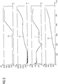
- FIG. 2 shows several stator-related and rotor-related electrical variables on a time scale t (in seconds) shown.
- FIG. 2 represents: the rotor current 10, the rotor voltage 11, the stator current 12 and the stator voltage 13 four sizes each in volts (V).
- the asynchronous machine is at standstill at time t of 0 s.
- FIG. 2 is a starting process of the asynchronous machine 1.
- the starting process of the asynchronous machine 1 is particularly important in the present method of controlling the excitation, since the fields of stator 2 and rotor 3 initially not usually aligned. This means that the phase position between stator 2 and rotor 3 is initially undefined. It is first necessary to align the fields of stator 2 and rotor 3 to each other.
- the rotor 3 is first operated with a rotor current 10 whose amplitude is less than a predetermined startup limit.
- the start-up limit value is smaller by a predetermined amount than a predetermined operating value, to which the amplitude of the rotor current 10 in a normal operation, for example, at rated power, of the asynchronous machine 1 is set.
- the frequency of the rotor current 10 is set to the line frequency of the power grid 6.
- the stator 2 or the winding arrangement 20 is initially still separated from the power grid 6.
- stator 2 or the winding assembly 20 is connected to the power grid 6. This is done, for example, by closing respective switches of the switching unit 21. This results in a compensation process, in which flow in the winding arrangement currents 20 and generate a torque on the rotor 3, so that the rotor 3 aligns in the field of the stator 2. As a result, the phase angle between the stator 2 and the rotor 3 is set appropriately.
- the predetermined start-up limit value is chosen to be sufficiently small so that the equalizing currents do not exceed a predetermined level.
- the asynchronous machine 1 it is possible to change the speed.
- the asynchronous machine 1 the possibility to control the speed.
- the frequencies of the stator current and / or the stator voltage or the frequencies of the rotor current and / or the rotor voltage are continuously changed in order to change the rotational speed. Due to the continuous change of the frequencies, the synchronism between stator 2 and rotor 3 is not lost.
- the frequency of rotor current and / or rotor voltage (rotational frequency) and the direction of rotation of the rotor rotating field can be changed so that an arbitrary speed of the rotor can be achieved.
- the amplitude of the rotor current or of the rotor voltage can be changed in order to control the active power as well as the reactive power of the asynchronous machine 1. For example, by setting a predetermined value for the amplitude of the rotor current or the rotor voltage, the active power and / or the reactive power of the asynchronous machine 1 is set to another predetermined value.
- FIG. 3 shows the same starting operation of the asynchronous machine 1 where other quantities are plotted on the same time axis t (in seconds): reactive electric power of the rotor 40 (in kVA), reactive electric power of the stator 41 (in kVA), effective electric power of the rotor 42 (in kW), Electric real power of the stator 43 (in kW), mechanical power of the asynchronous machine 44 (in kW) and speed of the rotor 46 (in revolutions per minute, rpm).
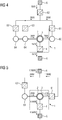
- FIG. 4 and the FIG. 5 each show an arrangement with the asynchronous machine 1.
- This can be test stands for the asynchronous machine 1.
- the characteristic diagram for the asynchronous machine 1 can be created on the test stands.
- the asynchronous machine 1 is shown in a test environment or on a test bench.
- the asynchronous machine 1 is in a generator mode.
- the asynchronous machine 1 is driven mechanically via two load machines 64. Electrical energy is fed from the rotor 3 of the asynchronous machine 1 in the power grid 6.
- electrical energy from the stator 2 of the asynchronous machine 1 is fed into a synchronous machine 60.
- the two load machines 64 are controlled by respective inverters 63.
- the inverters 63 are in turn supplied with voltage via voltage-controlled converters 61, 62.
- the excitation unit 4 is formed in this example as a current-controlled converter. Electrical and mechanical energy flows are the FIG. 4 refer to.
- FIG. 5 shows the asynchronous machine 1 in another test setup.
- the excitation unit 4 is designed as a current-controlled inverter.
- the electrical power from the stator 2 of the asynchronous machine 1 is in this case fed directly to the voltage-controlled converter 61.
- the test setup has only one load machine 64, which is controlled by an inverter 63.
Priority Applications (5)
| Application Number | Priority Date | Filing Date | Title |
|---|---|---|---|
| EP17198315.8A EP3477847A1 (fr) | 2017-10-25 | 2017-10-25 | Machine asynchrone à double alimentation ainsi que procédé de fonctionnement d'une machine asynchrone à double alimentation |
| EP18793626.5A EP3669453B1 (fr) | 2017-10-25 | 2018-10-19 | Procédé de fonctionnement d'une machine asynchrone à double alimentation |
| US16/759,181 US20200287488A1 (en) | 2017-10-25 | 2018-10-19 | Method for operating a double-fed asynchronous machine |
| CN201880069777.XA CN111279606A (zh) | 2017-10-25 | 2018-10-19 | 用于运行双馈异步电机的方法 |
| PCT/EP2018/078692 WO2019081366A1 (fr) | 2017-10-25 | 2018-10-19 | Procédé de fonctionnement d'une machine asynchrone à double alimentation |
Applications Claiming Priority (1)
| Application Number | Priority Date | Filing Date | Title |
|---|---|---|---|
| EP17198315.8A EP3477847A1 (fr) | 2017-10-25 | 2017-10-25 | Machine asynchrone à double alimentation ainsi que procédé de fonctionnement d'une machine asynchrone à double alimentation |
Publications (1)
| Publication Number | Publication Date |
|---|---|
| EP3477847A1 true EP3477847A1 (fr) | 2019-05-01 |
Family
ID=60182477
Family Applications (2)
| Application Number | Title | Priority Date | Filing Date |
|---|---|---|---|
| EP17198315.8A Withdrawn EP3477847A1 (fr) | 2017-10-25 | 2017-10-25 | Machine asynchrone à double alimentation ainsi que procédé de fonctionnement d'une machine asynchrone à double alimentation |
| EP18793626.5A Active EP3669453B1 (fr) | 2017-10-25 | 2018-10-19 | Procédé de fonctionnement d'une machine asynchrone à double alimentation |
Family Applications After (1)
| Application Number | Title | Priority Date | Filing Date |
|---|---|---|---|
| EP18793626.5A Active EP3669453B1 (fr) | 2017-10-25 | 2018-10-19 | Procédé de fonctionnement d'une machine asynchrone à double alimentation |
Country Status (4)
| Country | Link |
|---|---|
| US (1) | US20200287488A1 (fr) |
| EP (2) | EP3477847A1 (fr) |
| CN (1) | CN111279606A (fr) |
| WO (1) | WO2019081366A1 (fr) |
Cited By (1)
| Publication number | Priority date | Publication date | Assignee | Title |
|---|---|---|---|---|
| DE102020204716A1 (de) | 2020-04-15 | 2021-10-21 | Zf Friedrichshafen Ag | Elektrischer Generator |
Families Citing this family (2)
| Publication number | Priority date | Publication date | Assignee | Title |
|---|---|---|---|---|
| DE102020121414A1 (de) | 2020-08-14 | 2022-02-17 | Purem GmbH | Abgasheizanordnung |
| CN113093007B (zh) * | 2021-04-29 | 2023-02-07 | 哈动国家水力发电设备工程技术研究中心有限公司 | 一种可变速电机电动工况次同步负载试验方法 |
Citations (3)
| Publication number | Priority date | Publication date | Assignee | Title |
|---|---|---|---|---|
| EP2001120A2 (fr) * | 2007-06-08 | 2008-12-10 | Korean Electro Technology Research Institute | Contrôleur de générateur à induction à écran d'émission à double effet de champ |
| DE102008034531A1 (de) * | 2008-02-20 | 2009-08-27 | Repower Systems Ag | Windenergieanlage mit doppelt gespeistem Asynchrongenerator und Umrichterregelung |
| EP2200169A2 (fr) * | 2008-12-19 | 2010-06-23 | Converteam Technology Ltd | Procédé de démarrage d'une machine asynchrone à double alimentation |
Family Cites Families (7)
| Publication number | Priority date | Publication date | Assignee | Title |
|---|---|---|---|---|
| CN102158146A (zh) * | 2011-05-20 | 2011-08-17 | 南车株洲电力机车研究所有限公司 | 一种兆瓦级双馈电机的启动方法及装置 |
| CN102288913B (zh) * | 2011-08-12 | 2013-04-03 | 大连华锐重工集团股份有限公司 | 一种双馈电机测试系统及其测试方法 |
| CN103487753B (zh) * | 2012-06-11 | 2015-11-25 | 华锐风电科技(集团)股份有限公司 | 一种测试风力发电机组动态性能的方法及试验台 |
| CN105790298B (zh) * | 2014-12-23 | 2019-03-12 | 台达电子工业股份有限公司 | 风力发电控制装置及风力发电系统 |
| CN104836404A (zh) * | 2015-05-25 | 2015-08-12 | 湖南零陵恒远发电设备有限公司 | 一种双馈励磁机及其工作方法 |
| CN205178932U (zh) * | 2015-11-19 | 2016-04-20 | 安徽理工大学 | 基于双边pwm变流器的提升机双馈调速系统 |
| CN106864715A (zh) * | 2017-01-24 | 2017-06-20 | 同济大学 | 双馈式船舶混合轴带电机单机起动与推进的系统及方法 |
-
2017
- 2017-10-25 EP EP17198315.8A patent/EP3477847A1/fr not_active Withdrawn
-
2018
- 2018-10-19 US US16/759,181 patent/US20200287488A1/en not_active Abandoned
- 2018-10-19 CN CN201880069777.XA patent/CN111279606A/zh active Pending
- 2018-10-19 WO PCT/EP2018/078692 patent/WO2019081366A1/fr unknown
- 2018-10-19 EP EP18793626.5A patent/EP3669453B1/fr active Active
Patent Citations (3)
| Publication number | Priority date | Publication date | Assignee | Title |
|---|---|---|---|---|
| EP2001120A2 (fr) * | 2007-06-08 | 2008-12-10 | Korean Electro Technology Research Institute | Contrôleur de générateur à induction à écran d'émission à double effet de champ |
| DE102008034531A1 (de) * | 2008-02-20 | 2009-08-27 | Repower Systems Ag | Windenergieanlage mit doppelt gespeistem Asynchrongenerator und Umrichterregelung |
| EP2200169A2 (fr) * | 2008-12-19 | 2010-06-23 | Converteam Technology Ltd | Procédé de démarrage d'une machine asynchrone à double alimentation |
Cited By (1)
| Publication number | Priority date | Publication date | Assignee | Title |
|---|---|---|---|---|
| DE102020204716A1 (de) | 2020-04-15 | 2021-10-21 | Zf Friedrichshafen Ag | Elektrischer Generator |
Also Published As
| Publication number | Publication date |
|---|---|
| WO2019081366A1 (fr) | 2019-05-02 |
| EP3669453B1 (fr) | 2021-07-28 |
| US20200287488A1 (en) | 2020-09-10 |
| CN111279606A (zh) | 2020-06-12 |
| EP3669453A1 (fr) | 2020-06-24 |
Similar Documents
| Publication | Publication Date | Title |
|---|---|---|
| EP3669453B1 (fr) | Procédé de fonctionnement d'une machine asynchrone à double alimentation | |
| EP3644497B1 (fr) | Procédé et dispositif de commande virtuelle d'inertie de masse pour centrales pourvues de machine asynchrone à double alimentation | |
| EP3073631B1 (fr) | Éolienne comprenant un dispositif de suppression des vibrations subsynchrones | |
| EP3444937B1 (fr) | Système et procédé de fonctionnement d'une centrale de pompage pourvue d'une machine asynchrone à double alimentation | |
| DE102016124927A1 (de) | Flussschwächende Wechselstrommotorregelung durch Spannungsvektor-Winkelablenkung | |
| DE10219822A1 (de) | Verfahren und Vorrichtung zur sensorreduzierten Regelung einer permanentmagneterregten Synchronmaschine | |
| DE102013005355A1 (de) | Verfahren zum Betrieb eines bürstenlosen Motors und Motor | |
| EP2918009B1 (fr) | Système comportant un premier moteur électrique et un deuxième moteur électrique pour entraîner un ensemble d'éléments rotatifs | |
| EP1995456B1 (fr) | Commutation électrique destinée à tester un châssis, en particulier d'une éolienne | |
| DE102017221610A1 (de) | Ermittlung von zumindest einem Maschinenparameter einer E-Maschine | |
| DE102008052144A1 (de) | Synchronmaschine und Verfahren zum Betreiben einer Synchronmaschine | |
| EP3629468B1 (fr) | Procédé de fonctionnement d'une machine triphasée | |
| DE102004046966A1 (de) | Verfahren zur Ermittlung und Vorgabe von Parametern eines elektronischen Motorsteuergerätes und zugehöriger selbstparametrierender Drehstromsteller, insbesondere Sanftstarter | |
| EP2360830A1 (fr) | Procédé et dispositif de simulation d'un convertisseur électromécanique | |
| DE19752940C2 (de) | Verfahren und Vorrichtung zur dynamischen Leistungsregelung einer angetriebenen mehrphasigen Synchronmaschine | |
| EP2963803A1 (fr) | Alimentation d'une machine synchrone en courant d'excitation | |
| AT523109B1 (de) | Verfahren und System zum Kalibrieren einer Steuereinrichtung eines Elektromotors | |
| EP2628240B1 (fr) | Dispositif d'entraînement servant à entraîner un élément d'appareil ménager, appareil ménager et procédé pour faire fonctionner un appareil ménager | |
| WO2012127011A2 (fr) | Procédé de commande ou de régulation d'un moteur électrique rotatif et moteur électrique rotatif | |
| DE102016220014A1 (de) | Verfahren zum Steuern eines Wechselrichters einer elektrischen Maschine sowie Steuervorrichtung, elektrische Maschine und Kraftfahrzeug | |
| DE102016206059A1 (de) | Verfahren und Steuergerät zum Betreiben einer Drehfeldmaschine bei einem Stillstand oder Anfahren eines Rotors der Drehfeldmaschine, sowie Fabrzeugantriebsstrang | |
| DE102008026669A1 (de) | Verfahren und Schaltungsanordnung zum Betreiben von Schrittmotoren | |
| DE102008004039B4 (de) | Halbleiterschonende Ansteuerung eines Antriebssystems mit einem Pulsstromrichter und einem nachgeschalteten Asynchronmotor | |
| WO2005114830A1 (fr) | Dispositif convertisseur de frequence pour parc a energie eolienne et procede pour exploiter un tel dispositif | |
| DE202013102392U1 (de) | Steuerungsanordnung für eine Synchronmaschine |
Legal Events
| Date | Code | Title | Description |
|---|---|---|---|
| PUAI | Public reference made under article 153(3) epc to a published international application that has entered the european phase |
Free format text: ORIGINAL CODE: 0009012 |
|
| AK | Designated contracting states |
Kind code of ref document: A1 Designated state(s): AL AT BE BG CH CY CZ DE DK EE ES FI FR GB GR HR HU IE IS IT LI LT LU LV MC MK MT NL NO PL PT RO RS SE SI SK SM TR |
|
| AX | Request for extension of the european patent |
Extension state: BA ME |
|
| STAA | Information on the status of an ep patent application or granted ep patent |
Free format text: STATUS: THE APPLICATION IS DEEMED TO BE WITHDRAWN |
|
| 18D | Application deemed to be withdrawn |
Effective date: 20191105 |