EP3477847A1 - Double-fed asynchronous engine and method for operating a double-fed asynchronous engine - Google Patents
Double-fed asynchronous engine and method for operating a double-fed asynchronous engine Download PDFInfo
- Publication number
- EP3477847A1 EP3477847A1 EP17198315.8A EP17198315A EP3477847A1 EP 3477847 A1 EP3477847 A1 EP 3477847A1 EP 17198315 A EP17198315 A EP 17198315A EP 3477847 A1 EP3477847 A1 EP 3477847A1
- Authority
- EP
- European Patent Office
- Prior art keywords
- asynchronous machine
- stator
- excitation
- rotor
- unit
- Prior art date
- Legal status (The legal status is an assumption and is not a legal conclusion. Google has not performed a legal analysis and makes no representation as to the accuracy of the status listed.)
- Withdrawn
Links
Images


Classifications
-
- H—ELECTRICITY
- H02—GENERATION; CONVERSION OR DISTRIBUTION OF ELECTRIC POWER
- H02P—CONTROL OR REGULATION OF ELECTRIC MOTORS, ELECTRIC GENERATORS OR DYNAMO-ELECTRIC CONVERTERS; CONTROLLING TRANSFORMERS, REACTORS OR CHOKE COILS
- H02P9/00—Arrangements for controlling electric generators for the purpose of obtaining a desired output
- H02P9/007—Control circuits for doubly fed generators
-
- H—ELECTRICITY
- H02—GENERATION; CONVERSION OR DISTRIBUTION OF ELECTRIC POWER
- H02P—CONTROL OR REGULATION OF ELECTRIC MOTORS, ELECTRIC GENERATORS OR DYNAMO-ELECTRIC CONVERTERS; CONTROLLING TRANSFORMERS, REACTORS OR CHOKE COILS
- H02P1/00—Arrangements for starting electric motors or dynamo-electric converters
- H02P1/16—Arrangements for starting electric motors or dynamo-electric converters for starting dynamo-electric motors or dynamo-electric converters
- H02P1/26—Arrangements for starting electric motors or dynamo-electric converters for starting dynamo-electric motors or dynamo-electric converters for starting an individual polyphase induction motor
Definitions
- the invention relates to a double-fed asynchronous machine with a rotor having a field winding for exciting the asynchronous machine, as well as with a control unit for controlling the excitation unit.
- a second aspect of the invention relates to a method of operating a double-fed asynchronous machine.
- a double-fed asynchronous machine has a stator and a rotor.
- the stator comprises a winding arrangement, which in an operation of the asynchronous machine is preferably connected to a power grid, for example the 50 Hz interconnected grid.
- the rotor has an excitation winding, which is connected to a power converter, in particular a converter. About the inverter, the excitation winding can be indirectly connected to the power grid.
- electrical power can be fed from the network into the rotor or from the rotor into the network via the power converter.
- the speed of the rotor may be below the synchronous speed (under-synchronous operation) or above the synchronous speed (over-synchronous operation).
- an electrical power absorbed or emitted by the stator is regulated via the excitation of the asynchronous machine or of the rotor.
- an electrical voltage is applied to the field winding via the power converter and / or an electrical current is impressed into the field winding.
- the power converter has for this purpose a control unit, which speed and angle of the rotor via a rotary encoder and amplitude and phase of the voltage and / or the current in the winding assembly via electrical transducers.
- the excitation of the rotor is regulated as a function of the rotational speed and angle of the rotor as well as dependent on the amplitude and phase position of the voltage and / or the current in the winding arrangement.
- encoderless control method are known in which the angle of the rotor on the amplitudes and phase angles of the currents and voltages in the stator and the rotor is determined. In summary, it is always a closed loop for controlling the rotor voltage of the rotor current.
- a disadvantage of the prior art is that the power converter, in particular the inverter, must be designed specifically for the asynchronous machine.
- the invention provides that the control unit has no signaling or electrical connection to the stator, which goes beyond a pure power supply of the control unit, so that the at least one electrical variable regardless of electrical stator sizes of the winding assembly is adjustable by the control unit.
- the exciter unit is a current source or a voltage source.
- the winding arrangement of the stator is designed in particular three-phase. In an operation of the asynchronous machine, a three-phase current then flows through the winding arrangement as a stator current.
- the stator current refers to the total current flowing through the winding assembly.
- a stator voltage a voltage is referred to, which rests on the winding assembly. This is in particular a three-phase AC voltage.
- the stator voltage, the stator current and their phase position, for example to each other and / or with respect to a power grid, are examples of stator sizes.
- the excitation winding is designed in particular three-phase. Accordingly, the excitation unit can be set up to impress a current flow (rotor current) into the excitation winding and / or to apply a voltage (rotor voltage) to the exciter winding. As a result, the excitation of the asynchronous machine can be achieved. Depending on the operating point of the asynchronous machine, the exciter unit can be designed to feed electrical power into the exciter winding or to remove it from the exciter winding.
- the control unit may be configured to influence or control this current flow and / or this voltage by adjusting the at least one electrical variable.
- control unit may be configured to control the excitation of the asynchronous machine by predetermining the electrical variable, wherein the rotor current and / or the rotor voltage are in turn influenced or controlled by means of the electrical variable.
- the at least one electrical variable relates, for example, amplitude and / or frequency of the rotor current and / or the rotor voltage.
- the current flow or the voltage in the exciter winding can be adjusted by the control unit in such a way that results in the winding arrangement with respect to amplitude and / or phase position predetermined stator current.
- the control unit can be designed be to control the excitation so that there is a predetermined amplitude and / or phase position for the stator current. Since the control unit has no signaling or electrical connection to the stator, no feedback takes place here. Sizes related to the rotor, for example the rotor voltage and / or the rotor current, can be set by the control unit by setting the at least one electrical variable independently of the stator or without interaction with the stator. For example, the control unit is set up to set a predetermined value for the at least one electrical variable. Due to this form of control of the excitation of the asynchronous machine, requirements for the excitation unit and for measuring units are particularly low.
- the control unit and the excitation unit can be connected to a power grid, in particular the 50 Hz network.
- the exciter unit can be set up to inject electrical energy from the excitation winding into the power grid when impressing the rotor current or when applying the rotor voltage to the excitation winding or to feed electrical energy from the power grid into the exciter winding.
- the stator or the winding arrangement can be connected directly to the power grid.
- An embodiment of the invention provides that the control unit and the excitation unit can be connected to the power supply exclusively for supplying electrical energy and the winding arrangement can likewise be connected to the power grid, the control unit and the exciter unit being signal-technically or electrically connected to the stator exclusively in this way are connectable.
- the exciter unit and the control unit are connected exclusively via the power supply to the stator or the winding arrangement.
- the control unit may be designed to control the electrical variable or the Rotor current and / or the rotor voltage to specify at least partially based on a frequency of the power grid.
- the exciter unit is configured to connect the excitation winding to the power grid.
- the connection between the exciter winding and the power grid can be switched by the exciter unit.
- the excitation unit has at least one switching element for switching a mains voltage from the power supply to the exciter winding.
- the at least one switching element can be controlled or switched by the control unit. By suitable switching of the at least one switching element, the rotor current or the rotor voltage can be controlled in the field winding.
- the control unit is designed in particular for controlling the excitation unit according to an open control circuit. In other words, due to the lack of connection of the control unit to the stator no feedback on the basis of stator sizes. In particular, the control unit is not designed to compare the stator sizes with a desired value. On the contrary, the control unit is preferably designed to set or control the electrical variable or the rotor current and / or the rotor voltage free from the stator variables.
- control unit comprises a memory unit in which a characteristic diagram for setting the at least one electrical variable can be stored, and the control unit is designed to control the exciter unit based on the characteristic field.
- the at least one electrical variable for one or more operating points of the asynchronous machine is predefined by the characteristic map.
- the control unit may be designed to set the excitation unit by setting the at least one electrical variable to at least one predetermined characteristic map value which is read from the characteristic map.
- the map can for many operating points the asynchronous machine a suitable excitation can be specified.
- the map allows comprehensive control of the excitation without the need for feedback.
- the map can for example be determined or recorded in a test operation of the asynchronous machine.
- a development provides that a rotary encoder or a speed sensor is mounted on a shaft of the asynchronous machine.
- This shaft can be mechanically connected to the rotor.
- the shaft is arranged on the rotor and rotates uniformly to this.
- the control unit may be adapted to use its signal or its signals to the angle and / or the rotational direction and / or rotation of the rotor together with the angle and / or the direction of rotation and frequency of the rotor rotation field on the angle and / or direction of rotation To close the frequency of the stator rotary field.
- the frequency of the power grid that powers the stator can be determined and monitored without directly measuring stator sizes.
- the frequency of the power supply system supplying the stator is known from another source, eg when operating on the 50 Hz grid or through a control or regulation of the power supply system independent of the apparatus described here, it is also possible to increase the frequency of the To compare power network with the difference between the speed and the frequency of the rotor rotating field and thus to monitor that the Statorwebsectiond and the rotor rotating field synchronously (synchronism) and the asynchronous machine does not tilt.
- the control unit in this case, the known frequency of the power supply system can be specified.
- the control unit may be configured to perform the above-mentioned comparison and / or monitoring. Also in this case, it is not necessary that the stator current or the stator voltage be measured by the control unit.
- the excitation unit is designed as a power converter.
- the exciter unit can be designed as a converter.
- the power converter can be designed to direct the phase position, frequency and / or amplitude of the rotor current and / or the rotor voltage with respect to the mains voltage.
- the power converter can direct the grid voltage such that the phase, frequency and / or amplitude of the rotor current and / or the rotor voltage correspond to the at least one electrical variable set by the control unit.
- the power converter is a simple and effective way to controllably energize the rotor via the power grid.
- the excitation unit is designed universally for the provision or transformation of electrical energy independently of the asynchronous machine.
- the excitation unit is preferably not specifically designed for the purpose of excitation of the asynchronous machine, but universally applicable, for example as a power converter or inverter.
- the possibility of using a universally applicable power converter as the exciter unit results in a particularly simple construction of the asynchronous machine.
- the asynchronous machine can be connected to a load or to a drive.
- a shaft of the asynchronous machine which is part of the rotor, has a coupling element for coupling the shaft to the load or the drive.
- the load is, for example, a mechanical load, for example a mechanical machine, which can be driven by the asynchronous machine, or a further electric machine, a so-called load machine.
- the load from the asynchronous machine is operable in a motor operation of the asynchronous machine.
- the asynchronous machine may be configured to transmit torque to the load during engine operation.
- the drive is, for example, an electric machine, a turbine, for example in the power plant, or a wind turbine a wind turbine.
- the asynchronous machine may be configured to receive a torque from the drive.
- the asynchronous machine can be set in rotation by the drive.
- the asynchronous machine can be driven by the drive in a generator operation of the asynchronous machine.
- a torsional vibration damper On the shaft of the asynchronous machine, a torsional vibration damper can be provided.
- the torsional vibration damper may contribute a predetermined proportion to the moment of inertia of the rotor.
- the torsional vibration damper has a proportion of the moment of inertia of the rotor of 10%.
- the torsional vibration damper is, in particular, an additional moment of inertia resiliently mounted on the shaft. By damping the spring element oscillations of the shaft can be minimized.
- an attenuation can be achieved, for example, by mounting a fan wheel on the shaft.
- the torsional vibration damper, the fan wheel and the load, in particular the load machine are examples of how vibrations of the asynchronous machine can be reduced during operation.
- these vibrations can be reduced or compensated by the use of torsional vibration.
- a conventional asynchronous machine whose excitation by feedback in a closed loop can be controlled, such measures are not necessary.
- the at least one electrical variable is set independently of stator sizes of a winding arrangement of a stator of the asynchronous machine.
- the electrical quantity can be adjusted without feedback.
- the electrical variable is set, for example, solely on the basis of rotor-related variables.
- the method according to the invention is suitable for operating a doubly fed asynchronous machine of the type according to the invention.
- the method according to the invention and the asynchronous machine according to the invention thus relate to one another.
- features of the method according to the invention also form the asynchronous machine according to the invention and vice versa. Therefore, the features already described in the context of the asynchronous machine according to the invention are not described again here.
- the electrical quantity for the excitation is adjusted according to an open control loop.
- the excitation of the asynchronous machine or the rotor can be controlled according to the open loop.
- a feedback based on the stator sizes is dispensed with.
- the electrical variable is predefined on the basis of a characteristic map of the.
- a development provides that the amplitude and / or frequency of a voltage (rotor voltage) or a current flow (rotor current) are set as the at least one electrical variable for the excitation, so that in the stator, a predetermined phase position and a predetermined amplitude can be achieved. In particular, this results in a predetermined phase position and a predetermined amplitude of the stator current or the stator voltage in the winding arrangement of the stator reached. In this case, the phase position and / or the amplitude of the stator current is calculated, for example, since the feedback of the stator variables, that is, for example, stator current or stator voltage, is dispensed with.
- values for the amplitude and / or the frequency of the rotor voltage or of the rotor current are stored in the characteristic field, for which the predetermined phase position and the predetermined amplitude of the stator current or the stator voltage results. This way, the excitation of the rotor can be controlled particularly easily.
- the amplitude of the voltage (rotor voltage) and / or the current flow (rotor current) is selected to be smaller than a predetermined startup limit value and the frequency of the voltage (rotor voltage) and / or the current flow (rotor current) to a Mains frequency of a power grid to which the winding arrangement of the stator is connected, is set.
- the stator or the winding arrangement is connected to the power grid.
- the excitation winding is also indirectly connected to the power supply via the excitation unit.
- the excitation unit is preferably a power converter, in particular a converter.
- the grid frequency of the power grid can be measured on the rotor or on the exciter unit.
- the startup limit value may be fixed, for example by the map.
- the winding arrangement of the stator can then be connected or connected to the power grid.
- the phase position of the rotor and stator automatically adjusts itself.
- compensation currents can flow.
- a torque can be generated on the rotor, by which the phase position of the rotor and stator can be adjusted to each other by aligning the rotor.
- the equalizing currents can be kept less than a predetermined limit. This is particularly necessary because due to the lack of feedback or due to the open control (according to the open loop) no unique phase position of the rotor and stator is predetermined or adjustable. However, due to the starting process described, the phase position automatically adjusts to a continuous value.
- the amplitude of the voltage and / or the current flow can be set to a predetermined operating value.
- the predetermined operating value is, in particular, greater than the startup limit value by a predetermined amount.
- the operating value can be adapted to a rated power or a torque of the asynchronous machine.
- the predetermined startup limit value can be predetermined smaller by a predetermined amount.
- the starting process can also take place when the asynchronous machine is already rotating. This is the case, for example, when the asynchronous machine is operated as a generator and is brought to a certain speed by the drive machine.
- the direction and frequency of the rotor rotating field can be set so that the rotational frequency of the rotor rotating field together with the rotational speed of the rotor results in approximately the rotational frequency of the stator rotary field.
- the rotor rotating field can thereby move in the direction of rotation of the rotor and counter to the direction of rotation of the rotor.
- FIG. 1 shows a block diagram of a double-fed asynchronous machine 1, which comprises a stator 2, a rotor 3, an exciter unit 4 and a control unit 5.
- An excitation winding 30 of the rotor 3 can be connected via the excitation unit 4 to a power grid 6.
- a winding arrangement 20 (only shown very schematically in the FIG) can be connected to the power grid 6 via a switching unit 21.
- the winding assembly 20 is designed in particular three-phase, which is why a compound 22 has three phase strands.
- the switching unit 21 may be part of the asynchronous machine 1.
- the electrical connection 22 between the stator 2 and the power grid 6 can be switched.
- electrical connection 22 is separable by the switching unit 21.
- the rotor 3 or the asynchronous machine 1 can be excited via the field winding 30 of the rotor 3.
- the excitation is carried out via the excitation unit 4.
- the excitation is controlled by the control unit 5, which specifies at least one electrical variable for the excitation.
- the control unit 5 may comprise a memory unit 50 in which predetermined criteria for setting the at least one electrical variable can be stored. For example, a map for the at least one electrical variable is stored in the memory unit 50.
- the at least one electrical variable which is set for the excitation relates in particular to a frequency and an amplitude of a current flow (rotor current) or a voltage (rotor voltage) in the excitation winding 30. In other words, preferably at least two electrical quantities are set for the excitation.
- the excitation of the asynchronous machine 1 or rotor 3 can be controlled.
- the excitation unit 4 is presently designed as a power converter, in particular as a converter. Via the excitation unit 4, the rotor current and / or the rotor voltage of the excitation winding 30 is controlled or regulated such that the rotor current or the rotor voltage of the at least one electrical variable, which is set by the control unit 5 corresponds.
- the excitation unit 4 has one or more switching elements, which are controlled by the control unit 5.
- the switching elements are, in particular, transistors, preferably field effect transistors, or IGBTs (Insulated Gate Bipolar Transistor).
- electrical power can be fed from the exciter winding 30 into the power grid 6 or from the power grid 6 into the excitation winding 30 by the exciter unit 4.
- stator sizes are, for example, stator currents or stator voltages.
- Stator currents and stator voltages are, for example, individual phase currents of the individual phases of the winding arrangement 20 as well as a resulting total current or a resulting total voltage.
- Further examples of stator sizes are speed of the rotor 3 with respect to the stator 2 and an angle of the rotor 3 with respect to the stator 2. These are sizes which are measured according to the prior art, for example, a rotary encoder of the stator.
- the excitation of the rotor 3 or the at least one electrical variable is controlled in the present case in the sense of an open loop. Therefore, the interaction between the stator 2 and the exciter unit 4 and the control unit 5 can be dispensed with.
- different values for the at least one physical variable can be predefined for a plurality of operating points or operating states of the asynchronous machine 1. The control of the rotor voltage or the rotor current is thus independent of the stator-related variables.
- the excitation unit 4 can be designed as a universally applicable power converter. In particular, no special adaptation of the excitation unit 4 to the asynchronous machine 1 is necessary. The adaptation of the excitation of the asynchronous machine 1 takes place here exclusively by the control unit 5.
- the stator 2 or the winding arrangement 20 in a normal operation of the asynchronous machine 1 directly, which means unregulated, connected to the power grid 6. That is, the switching unit 21 establishes a direct electrical connection 22 of the phase strands to the power grid 6.
- the power grid 6 is the general 50 Hz network
- the grid voltage of the power grid 6 is fixed and can not be changed by the operation of the asynchronous machine 1, as an electric motor or as a generator. Therefore, the power grid 6 in this case is a voltage source.
- the excitation unit 4 in this case represents a power source.
- both the winding arrangement 20 and the excitation winding 30 are connected in each case to a current source or to a voltage source.
- the winding arrangement 20 is connected to a current source and the excitation winding 30 to a voltage source or conversely that the winding arrangement 20 is a voltage source and the excitation winding 30 is connected to a power source.
- the stator 2 is preferably connected statically to the power network 6, which is often a voltage source, it has proven to be advantageous to design the exciter unit 4 as a current source.
- the rotor 3 or a shaft, which is part of the rotor 3 or is connected to the rotor 3, has a torsional vibration damper.
- the torsional vibration damper has an inertia, which is for example 10% of the rotor 3.
- the moment of inertia of the torsional vibration damper can be mounted resiliently on the shaft.
- the moment of inertia of the torsional vibration damper elastic and dampened connected to the shaft.
- a fan may be arranged on the shaft.
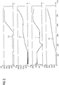
- FIG. 2 shows several stator-related and rotor-related electrical variables on a time scale t (in seconds) shown.
- FIG. 2 represents: the rotor current 10, the rotor voltage 11, the stator current 12 and the stator voltage 13 four sizes each in volts (V).
- the asynchronous machine is at standstill at time t of 0 s.
- FIG. 2 is a starting process of the asynchronous machine 1.
- the starting process of the asynchronous machine 1 is particularly important in the present method of controlling the excitation, since the fields of stator 2 and rotor 3 initially not usually aligned. This means that the phase position between stator 2 and rotor 3 is initially undefined. It is first necessary to align the fields of stator 2 and rotor 3 to each other.
- the rotor 3 is first operated with a rotor current 10 whose amplitude is less than a predetermined startup limit.
- the start-up limit value is smaller by a predetermined amount than a predetermined operating value, to which the amplitude of the rotor current 10 in a normal operation, for example, at rated power, of the asynchronous machine 1 is set.
- the frequency of the rotor current 10 is set to the line frequency of the power grid 6.
- the stator 2 or the winding arrangement 20 is initially still separated from the power grid 6.
- stator 2 or the winding assembly 20 is connected to the power grid 6. This is done, for example, by closing respective switches of the switching unit 21. This results in a compensation process, in which flow in the winding arrangement currents 20 and generate a torque on the rotor 3, so that the rotor 3 aligns in the field of the stator 2. As a result, the phase angle between the stator 2 and the rotor 3 is set appropriately.
- the predetermined start-up limit value is chosen to be sufficiently small so that the equalizing currents do not exceed a predetermined level.
- the asynchronous machine 1 it is possible to change the speed.
- the asynchronous machine 1 the possibility to control the speed.
- the frequencies of the stator current and / or the stator voltage or the frequencies of the rotor current and / or the rotor voltage are continuously changed in order to change the rotational speed. Due to the continuous change of the frequencies, the synchronism between stator 2 and rotor 3 is not lost.
- the frequency of rotor current and / or rotor voltage (rotational frequency) and the direction of rotation of the rotor rotating field can be changed so that an arbitrary speed of the rotor can be achieved.
- the amplitude of the rotor current or of the rotor voltage can be changed in order to control the active power as well as the reactive power of the asynchronous machine 1. For example, by setting a predetermined value for the amplitude of the rotor current or the rotor voltage, the active power and / or the reactive power of the asynchronous machine 1 is set to another predetermined value.
- FIG. 3 shows the same starting operation of the asynchronous machine 1 where other quantities are plotted on the same time axis t (in seconds): reactive electric power of the rotor 40 (in kVA), reactive electric power of the stator 41 (in kVA), effective electric power of the rotor 42 (in kW), Electric real power of the stator 43 (in kW), mechanical power of the asynchronous machine 44 (in kW) and speed of the rotor 46 (in revolutions per minute, rpm).
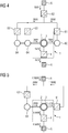
- FIG. 4 and the FIG. 5 each show an arrangement with the asynchronous machine 1.
- This can be test stands for the asynchronous machine 1.
- the characteristic diagram for the asynchronous machine 1 can be created on the test stands.
- the asynchronous machine 1 is shown in a test environment or on a test bench.
- the asynchronous machine 1 is in a generator mode.
- the asynchronous machine 1 is driven mechanically via two load machines 64. Electrical energy is fed from the rotor 3 of the asynchronous machine 1 in the power grid 6.
- electrical energy from the stator 2 of the asynchronous machine 1 is fed into a synchronous machine 60.
- the two load machines 64 are controlled by respective inverters 63.
- the inverters 63 are in turn supplied with voltage via voltage-controlled converters 61, 62.
- the excitation unit 4 is formed in this example as a current-controlled converter. Electrical and mechanical energy flows are the FIG. 4 refer to.
- FIG. 5 shows the asynchronous machine 1 in another test setup.
- the excitation unit 4 is designed as a current-controlled inverter.
- the electrical power from the stator 2 of the asynchronous machine 1 is in this case fed directly to the voltage-controlled converter 61.
- the test setup has only one load machine 64, which is controlled by an inverter 63.
Abstract
Die Erfindung betrifft eine doppelt gespeiste Asynchronmaschine (1), mit
- einem Rotor (3), der eine Erregerwicklung (30) aufweist,
- einem Stator (2), der eine Wicklungsanordnung (20) umfasst,
- einer elektrischen Erregereinheit (4) zum Erregen der Asynchronmaschine (1) über die Erregerwicklung (30), und
- einer Steuereinheit (5) zum Steuern der Erregereinheit (4) durch Einstellen zumindest einer elektrischen Größe für das Erregen.The invention relates to a double-fed asynchronous machine (1), with
a rotor (3) having a field winding (30),
a stator (2) comprising a winding arrangement (20),
- An electrical excitation unit (4) for energizing the asynchronous machine (1) via the excitation winding (30), and
- A control unit (5) for controlling the exciter unit (4) by adjusting at least one electrical quantity for the excitation.
Um eine erleichterte Steuerung der Erregung der Asynchronmaschine (1) zu ermöglichen, ist vorgesehen, dass
- die Steuereinheit (5) keine signaltechnische oder elektrische Verbindung zu dem Stator (2) aufweist, welche über eine reine Energieversorgung der Steuereinheit (5) hinausgeht, sodass die zumindest eine elektrische Größe unabhängig von elektrischen Statorgrößen der Wicklungsanordnung (20) von der Steuereinheit (5) einstellbar ist.

- The control unit (5) has no signaling or electrical connection to the stator (2), which goes beyond a pure power supply of the control unit (5), so that the at least one electrical variable regardless of electrical stator sizes of the winding assembly (20) from the control unit ( 5) is adjustable.
Description
Die Erfindung betrifft eine doppelt gespeiste Asynchronmaschine mit einem Rotor, der eine Erregerwicklung zum Erregen der Asynchronmaschine aufweist, sowie mit einer Steuereinheit zum Steuern der Erregereinheit. Ein zweiter Aspekt der Erfindung betrifft ein Verfahren zum Betreiben einer doppelt gespeisten Asynchronmaschine.The invention relates to a double-fed asynchronous machine with a rotor having a field winding for exciting the asynchronous machine, as well as with a control unit for controlling the excitation unit. A second aspect of the invention relates to a method of operating a double-fed asynchronous machine.
Eine doppelt gespeiste Asynchronmaschine weist einen Stator und einen Rotor auf. Der Stator umfasst eine Wicklungsanordnung, welche in einem Betrieb der Asynchronmaschine vorzugsweise mit einem Stromnetz, beispielsweise dem 50 Hz-Verbundnetz, verbunden ist. Der Rotor weist eine Erregerwicklung auf, welche mit einem Stromrichter, insbesondere einem Umrichter, verbunden ist. Über den Umrichter kann die Erregerwicklung indirekt mit dem Stromnetz verbunden sein. Über den Stromrichter kann je nach Betriebsmodus der Asynchronmaschine elektrische Energie aus dem Netz in den Rotor oder von dem Rotor in das Netz gespeist werden. Dabei kann die Drehzahl des Rotors unter der Synchrondrehzahl liegen (untersynchroner Betrieb) oder über der Synchrondrehzahl (übersynchroner Betrieb).A double-fed asynchronous machine has a stator and a rotor. The stator comprises a winding arrangement, which in an operation of the asynchronous machine is preferably connected to a power grid, for example the 50 Hz interconnected grid. The rotor has an excitation winding, which is connected to a power converter, in particular a converter. About the inverter, the excitation winding can be indirectly connected to the power grid. Depending on the mode of operation of the asynchronous machine, electrical power can be fed from the network into the rotor or from the rotor into the network via the power converter. The speed of the rotor may be below the synchronous speed (under-synchronous operation) or above the synchronous speed (over-synchronous operation).
Über die Erregerwicklung wird die Asynchronmaschine erregt. Dabei wird eine vom Stator aufgenommene oder abgegebene elektrische Leistung (Wirkleistung und Blindleistung) über die Erregung der Asynchronmaschine beziehungsweise des Rotors geregelt. Zum Erregen des Rotors beziehungsweise der Asynchronmaschine wird über den Stromrichter eine elektrische Spannung an der Erregerwicklung angelegt und/oder ein elektrischer Strom in die Erregerwicklung eingeprägt. Der Stromrichter weist hierzu eine Steuereinheit auf, welche Drehzahl und Winkel des Rotors über einen Drehgeber und Amplitude und Phasenlage der Spannung und/oder des Stroms in der Wicklungsanordnung über elektrische Messwandler misst. Mit anderen Worten wird die Erregung des Rotors abhängig von Drehzahl und Winkel des Rotors sowie abhängig von Amplitude und Phasenlage der Spannung und/oder des Stroms in der Wicklungsanordnung geregelt.About the exciter winding the asynchronous machine is energized. In this case, an electrical power absorbed or emitted by the stator (active power and reactive power) is regulated via the excitation of the asynchronous machine or of the rotor. To excite the rotor or the asynchronous machine, an electrical voltage is applied to the field winding via the power converter and / or an electrical current is impressed into the field winding. The power converter has for this purpose a control unit, which speed and angle of the rotor via a rotary encoder and amplitude and phase of the voltage and / or the current in the winding assembly via electrical transducers. In other words, the excitation of the rotor is regulated as a function of the rotational speed and angle of the rotor as well as dependent on the amplitude and phase position of the voltage and / or the current in the winding arrangement.
Außerdem sind drehgeberlose Regelverfahren bekannt, bei welchen die Winkel des Rotors über die Amplituden und Phasenlagen der Ströme und Spannungen im Stator und im Rotor bestimmt wird. Zusammengefasst handelt es sich stets um einen geschlossenen Regelkreis für die Regelung der Rotorspannung des Rotorstroms.In addition, encoderless control method are known in which the angle of the rotor on the amplitudes and phase angles of the currents and voltages in the stator and the rotor is determined. In summary, it is always a closed loop for controlling the rotor voltage of the rotor current.
Nachteilig am Stand der Technik ist, dass der Stromrichter, insbesondere der Umrichter, spezifisch für die Asynchronmaschine ausgelegt sein muss.A disadvantage of the prior art is that the power converter, in particular the inverter, must be designed specifically for the asynchronous machine.
Es ist Aufgabe der vorliegenden Erfindung, eine erleichterte Steuerung der Erregung der Asynchronmaschine zu ermöglichen.It is an object of the present invention to facilitate facilitated control of the excitation of the asynchronous machine.
Die Erfindung geht aus von einer doppelt gespeisten Asynchronmaschine, mit
- einem Rotor, der eine Erregerwicklung aufweist,
- einem Stator, der eine Wicklungsanordnung umfasst,
- einer elektrischen Erregereinheit zum Erregen der Asynchronmaschine über die Erregerwicklung, und
- einer Steuereinheit zum Steuern der Erregereinheit durch Einstellen zumindest einer elektrischen Größe für das Erregen.
- a rotor having a field winding,
- a stator comprising a winding arrangement,
- an electrical exciter unit for exciting the asynchronous machine via the exciter winding, and
- a control unit for controlling the exciter unit by setting at least one electrical quantity for excitation.
Um nun eine erleichterte Steuerung der Erregung der Asynchronmaschine zu ermöglichen, ist erfindungsgemäß vorgesehen, dass die Steuereinheit keine signaltechnische oder elektrische Verbindung zu dem Stator aufweist, welche über eine reine Energieversorgung der Steuereinheit hinausgeht, sodass die zumindest eine elektrische Größe unabhängig von elektrischen Statorgrößen der Wicklungsanordnung von der Steuereinheit einstellbar ist.In order to facilitate facilitated control of the excitation of the asynchronous machine, the invention provides that the control unit has no signaling or electrical connection to the stator, which goes beyond a pure power supply of the control unit, so that the at least one electrical variable regardless of electrical stator sizes of the winding assembly is adjustable by the control unit.
Beispielsweise handelt es sich bei der Erregereinheit um eine Stromquelle oder eine Spannungsquelle. Die Wicklungsanordnung des Stators ist insbesondere dreiphasig ausgeführt. In einem Betrieb der Asynchronmaschine fließt dann ein Drehstrom als ein Statorstrom durch die Wicklungsanordnung. Der Statorstrom bezeichnet den Gesamtstrom, welcher durch die Wicklungsanordnung fließt. Als Statorspannung wird eine Spannung bezeichnet, welche an der Wicklungsanordnung anliegt. Dabei handelt es sich insbesondere um eine Dreiphasenwechselspannung. Die Statorspannung, der Statorstrom sowie deren Phasenlage, beispielsweise zueinander und/oder bezogen auf ein Stromnetz, sind Beispiele für Statorgrößen.For example, the exciter unit is a current source or a voltage source. The winding arrangement of the stator is designed in particular three-phase. In an operation of the asynchronous machine, a three-phase current then flows through the winding arrangement as a stator current. The stator current refers to the total current flowing through the winding assembly. As a stator voltage, a voltage is referred to, which rests on the winding assembly. This is in particular a three-phase AC voltage. The stator voltage, the stator current and their phase position, for example to each other and / or with respect to a power grid, are examples of stator sizes.
Die Erregerwicklung ist insbesondere dreiphasig ausgeführt. Die Erregereinheit kann demnach dazu eingerichtet sein, einen Stromfluss (Rotorstrom) in die Erregerwicklung einzuprägen und/oder eine Spannung (Rotorspannung) an der Erregerwicklung anzulegen. Hierdurch kann die Erregung der Asynchronmaschine erreicht werden. Die Erregereinheit kann dazu ausgebildet sein, je nach Betriebspunkt der Asynchronmaschine elektrische Leistung in die Erregerwicklung einzuspeisen oder aus der Erregerwicklung zu entnehmen. Die Steuereinheit kann dazu eingerichtet sein, diesen Stromfluss und/oder diese Spannung durch Einstellen der zumindest einen elektrischen Größe zu beeinflussen beziehungsweise zu steuern. Mit anderen Worten kann die Steuereinheit dazu eingerichtet sein, die Erregung der Asynchronmaschine durch Vorgeben der elektrischen Größe zu steuern, wobei mittels der elektrischen Größe wiederum der Rotorstrom und/oder die Rotorspannung beeinflusst beziehungsweise gesteuert werden. Die zumindest eine elektrische Größe betrifft beispielsweise Amplitude und/oder Frequenz des Rotorstroms und/oder der Rotorspannung.The excitation winding is designed in particular three-phase. Accordingly, the excitation unit can be set up to impress a current flow (rotor current) into the excitation winding and / or to apply a voltage (rotor voltage) to the exciter winding. As a result, the excitation of the asynchronous machine can be achieved. Depending on the operating point of the asynchronous machine, the exciter unit can be designed to feed electrical power into the exciter winding or to remove it from the exciter winding. The control unit may be configured to influence or control this current flow and / or this voltage by adjusting the at least one electrical variable. In other words, the control unit may be configured to control the excitation of the asynchronous machine by predetermining the electrical variable, wherein the rotor current and / or the rotor voltage are in turn influenced or controlled by means of the electrical variable. The at least one electrical variable relates, for example, amplitude and / or frequency of the rotor current and / or the rotor voltage.
Der Stromfluss beziehungsweise die Spannung in der Erregerwicklung kann durch die Steuereinheit derart einstellbar sein, dass sich in der Wicklungsanordnung ein bezüglich Amplitude und/oder Phasenlage vorbestimmter Statorstrom ergibt. Mit anderen Worten kann die Steuereinheit dazu ausgebildet sein, die Erregung so zu steuern, dass sich für den Statorstrom eine vorbestimmte Amplitude und/oder Phasenlage ergibt. Da die Steuereinheit keine signaltechnische oder elektrische Verbindung zu dem Stator aufweist, findet hierbei keine Rückkopplung statt. Auf den Rotor bezogene Größen, beispielsweise die Rotorspannung und/oder der Rotorstrom, sind durch die Steuereinheit durch Einstellen der zumindest einen elektrischen Größe unabhängig von dem Stator beziehungsweise ohne Interaktion mit dem Stator einstellbar. Beispielsweise ist die Steuereinheit eingerichtet, für die zumindest eine elektrische Größe einen vorbestimmten Wert einzustellen. Durch diese Form der Steuerung der Erregung der Asynchronmaschine sind Anforderungen an die Erregereinheit sowie an Messeinheiten besonders gering.The current flow or the voltage in the exciter winding can be adjusted by the control unit in such a way that results in the winding arrangement with respect to amplitude and / or phase position predetermined stator current. In other words, the control unit can be designed be to control the excitation so that there is a predetermined amplitude and / or phase position for the stator current. Since the control unit has no signaling or electrical connection to the stator, no feedback takes place here. Sizes related to the rotor, for example the rotor voltage and / or the rotor current, can be set by the control unit by setting the at least one electrical variable independently of the stator or without interaction with the stator. For example, the control unit is set up to set a predetermined value for the at least one electrical variable. Due to this form of control of the excitation of the asynchronous machine, requirements for the excitation unit and for measuring units are particularly low.
Die Steuereinheit und die Erregereinheit können mit einem Stromnetz, insbesondere dem 50 Hz-Verbundnetz, verbindbar sein. In diesem Fall kann die Erregereinheit dazu eingerichtet sein, beim Einprägen des Rotorstroms beziehungsweise beim Anlegen der Rotorspannung an die Erregerwicklung elektrische Energie aus der Erregerwicklung in das Stromnetz einzuspeisen oder elektrische Energie aus dem Stromnetz in die Erregerwicklung einzuspeisen. Der Stator beziehungsweise die Wicklungsanordnung kann direkt mit dem Stromnetz verbindbar sein.The control unit and the excitation unit can be connected to a power grid, in particular the 50 Hz network. In this case, the exciter unit can be set up to inject electrical energy from the excitation winding into the power grid when impressing the rotor current or when applying the rotor voltage to the excitation winding or to feed electrical energy from the power grid into the exciter winding. The stator or the winding arrangement can be connected directly to the power grid.
Eine Ausgestaltungsform der Erfindung sieht vor, dass die Steuereinheit und die Erregereinheit ausschließlich zur Versorgung mit elektrischer Energie mit dem Stromnetz verbindbar sind und die Wicklungsanordnung ebenfalls mit dem Stromnetz verbindbar ist, wobei die Steuereinheit und die Erregereinheit ausschließlich auf diese Weise signaltechnisch oder elektrisch mit dem Stator verbindbar sind. Mit anderen Worten sind in einem Betrieb der Asynchronmaschine an dem Stromnetz die Erregereinheit und die Steuereinheit ausschließlich über das Stromnetz mit dem Stator beziehungsweise der Wicklungsanordnung verbunden. Die Steuereinheit kann stattdessen dazu ausgebildet sein, die elektrische Größe beziehungsweise den Rotorstrom und/oder die Rotorspannung zumindest teilweise basierend auf einer Frequenz des Stromnetzes vorzugeben.An embodiment of the invention provides that the control unit and the excitation unit can be connected to the power supply exclusively for supplying electrical energy and the winding arrangement can likewise be connected to the power grid, the control unit and the exciter unit being signal-technically or electrically connected to the stator exclusively in this way are connectable. In other words, in an operation of the asynchronous machine to the power grid, the exciter unit and the control unit are connected exclusively via the power supply to the stator or the winding arrangement. Instead, the control unit may be designed to control the electrical variable or the Rotor current and / or the rotor voltage to specify at least partially based on a frequency of the power grid.
Insbesondere ist die Erregereinheit dazu eingerichtet, die Erregerwicklung mit dem Stromnetz zu verbinden. Dabei kann die Verbindung zwischen Erregerwicklung und Stromnetz durch die Erregereinheit schaltbar sein. Beispielsweise weist die Erregereinheit zumindest ein Schaltelement zum Durchschalten einer Netzspannung von dem Stromnetz auf die Erregerwicklung auf. Das zumindest eine Schaltelement kann durch die Steuereinheit gesteuert beziehungsweise geschaltet werden. Durch geeignetes Schalten des zumindest einen Schaltelements ist in der Erregerwicklung der Rotorstrom beziehungsweise die Rotorspannung steuerbar.In particular, the exciter unit is configured to connect the excitation winding to the power grid. In this case, the connection between the exciter winding and the power grid can be switched by the exciter unit. For example, the excitation unit has at least one switching element for switching a mains voltage from the power supply to the exciter winding. The at least one switching element can be controlled or switched by the control unit. By suitable switching of the at least one switching element, the rotor current or the rotor voltage can be controlled in the field winding.
Die Steuereinheit ist insbesondere zur Steuerung der Erregereinheit gemäß einem offenen Regelkreislauf ausgebildet. Mit anderen Worten wird aufgrund der fehlenden Verbindung der Steuereinheit zu dem Stator keine Rückkopplung anhand von Statorgrößen auf. Insbesondere ist die Steuereinheit nicht dazu ausgebildet, die Statorgrößen mit einem Sollwert zu vergleichen. Im Gegenteil ist die Steuereinheit vorzugsweise dazu ausgebildet, die elektrische Größe beziehungsweise den Rotorstrom und/oder die Rotorspannung frei von den Statorgrößen einzustellen beziehungsweise zu steuern.The control unit is designed in particular for controlling the excitation unit according to an open control circuit. In other words, due to the lack of connection of the control unit to the stator no feedback on the basis of stator sizes. In particular, the control unit is not designed to compare the stator sizes with a desired value. On the contrary, the control unit is preferably designed to set or control the electrical variable or the rotor current and / or the rotor voltage free from the stator variables.
Eine Weiterbildung sieht vor, dass die Steuereinheit eine Speichereinheit umfasst, in welcher ein Kennfeld zum Einstellen der zumindest einen elektrischen Größe speicherbar ist, und die Steuereinheit dazu ausgebildet ist, die Erregereinheit anhand des Kennfelds zu steuern. Beispielsweise ist durch das Kennfeld die zumindest eine elektrische Größe für einen oder mehrere Betriebspunkte der Asynchronmaschine fest vorgegeben. Die Steuereinheit kann in diesem Fall dazu ausgebildet sein, die Erregereinheit durch Einstellen der zumindest einen elektrischen Größe auf zumindest einen vorgegebenen Kennfeldwert, welcher aus dem Kennfeld ausgelesen wird, einzustellen. Durch das Kennfeld kann für viele Betriebspunkte der Asynchronmaschine eine passende Erregung vorgegeben werden. Insbesondere ist durch das Kennfeld eine umfassende Steuerung der Erregung möglich, ohne die Notwendigkeit der Rückkopplung. Das Kennfeld kann beispielsweise in einem Testbetrieb der Asynchronmaschine ermittelt beziehungsweise aufgezeichnet werden.A development provides that the control unit comprises a memory unit in which a characteristic diagram for setting the at least one electrical variable can be stored, and the control unit is designed to control the exciter unit based on the characteristic field. For example, the at least one electrical variable for one or more operating points of the asynchronous machine is predefined by the characteristic map. In this case, the control unit may be designed to set the excitation unit by setting the at least one electrical variable to at least one predetermined characteristic map value which is read from the characteristic map. Through the map can for many operating points the asynchronous machine a suitable excitation can be specified. In particular, the map allows comprehensive control of the excitation without the need for feedback. The map can for example be determined or recorded in a test operation of the asynchronous machine.
Eine Weiterbildung sieht vor, dass ein Drehwinkelgeber oder ein Drehzahlgeber auf einer Welle der Asynchronmaschine montiert ist. Diese Welle kann mechanisch mit dem Rotor verbunden sein. Insbesondere ist die Welle am Rotor angeordnet und rotiert gleichförmig zu diesem. Die Steuereinheit kann dazu eingerichtet sein, dessen Signal oder deren Signale zu verwenden, um von dem Drehwinkel und/oder der Drehrichtung und Drehzahl des Rotors zusammen mit dem Winkel und/oder der Drehrichtung und Frequenz des Rotordrehfeldes auf den Winkel und/oder der Drehrichtung und Frequenz des Statordrehfeldes zu schließen. Dadurch kann beispielsweise die Frequenz des Stromnetzes, das den Stator speist, bestimmt und überwacht werden, ohne direkt Statorgrößen zu messen.A development provides that a rotary encoder or a speed sensor is mounted on a shaft of the asynchronous machine. This shaft can be mechanically connected to the rotor. In particular, the shaft is arranged on the rotor and rotates uniformly to this. The control unit may be adapted to use its signal or its signals to the angle and / or the rotational direction and / or rotation of the rotor together with the angle and / or the direction of rotation and frequency of the rotor rotation field on the angle and / or direction of rotation To close the frequency of the stator rotary field. As a result, for example, the frequency of the power grid that powers the stator can be determined and monitored without directly measuring stator sizes.
Ist die Frequenz des Stromnetzes, das den Stator speist, aus einer anderen Quelle bekannt, z.B. beim Betrieb am 50 Hz-Verbundnetz oder durch eine durch eine von der hier beschriebenen Apparatur unabhängigen Steuerung oder Regelung des Stromnetzes, ist es ferner möglich, die Frequenz des Stromnetzes mit der Differenz aus der Drehzahl und der Frequenz des Rotordrehfeldes zu vergleichen und damit zu überwachen, dass das Statordrehfehld und das Rotordrehfeld synchron laufen (Synchronismus) und die Asynchronmaschine nicht kippt. Insbesondere ist der Steuereinheit in diesem Fall die bekannte Frequenz des Stromnetzes vorgebbar. Die Steuereinheit kann dazu eingerichtet sein, das oben genannte Vergleichen und/oder Überwachen durchzuführen. Auch in diesem Fall ist es nicht erforderlich, dass der Statorstrom oder die Statorspannung von der Steuereinheit gemessen werden.If the frequency of the power supply system supplying the stator is known from another source, eg when operating on the 50 Hz grid or through a control or regulation of the power supply system independent of the apparatus described here, it is also possible to increase the frequency of the To compare power network with the difference between the speed and the frequency of the rotor rotating field and thus to monitor that the Statordrehfehld and the rotor rotating field synchronously (synchronism) and the asynchronous machine does not tilt. In particular, the control unit in this case, the known frequency of the power supply system can be specified. The control unit may be configured to perform the above-mentioned comparison and / or monitoring. Also in this case, it is not necessary that the stator current or the stator voltage be measured by the control unit.
Eine Weiterbildung sieht vor, dass die Erregereinheit als Stromrichter ausgeführt ist. Insbesondere kann die Erregereinheit als Umrichter ausgeführt sein. Der Stromrichter kann dazu ausgebildet sein, Phasenlage, Frequenz und/oder Amplitude des Rotorstroms und/oder der Rotorspannung bezüglich der Netzspannung zu richten. Mit anderen Worten kann der Stromrichter die Netzspannung derart richten, dass Phase, Frequenz und/oder Amplitude des Rotorstroms und/oder der Rotorspannung der durch die Steuereinheit eingestellten zumindest einen elektrischen Größe entsprechen. Der Stromrichter ist eine einfache und effektive Möglichkeit, den Rotor über das Stromnetz steuerbar zu erregen.A further embodiment provides that the excitation unit is designed as a power converter. In particular, the exciter unit can be designed as a converter. The power converter can be designed to direct the phase position, frequency and / or amplitude of the rotor current and / or the rotor voltage with respect to the mains voltage. In other words, the power converter can direct the grid voltage such that the phase, frequency and / or amplitude of the rotor current and / or the rotor voltage correspond to the at least one electrical variable set by the control unit. The power converter is a simple and effective way to controllably energize the rotor via the power grid.
Eine Weiterbildung sieht vor, dass die Erregereinheit universell zur Bereitstellung oder Umformung elektrischer Energie unabhängig von der Asynchronmaschine ausgebildet ist. Mit anderen Worten ist die Erregereinheit bevorzugt nicht spezifisch auf den Zweck der Erregung der Asynchronmaschine ausgebildet, sondern universell einsetzbar, beispielsweise als Stromrichter oder Umrichter. Insbesondere ergibt sich durch die Möglichkeit der Verwendung eines universell einsetzbaren Stromrichters als die Erregereinheit ein besonders einfacher Aufbau der Asynchronmaschine.A development provides that the excitation unit is designed universally for the provision or transformation of electrical energy independently of the asynchronous machine. In other words, the excitation unit is preferably not specifically designed for the purpose of excitation of the asynchronous machine, but universally applicable, for example as a power converter or inverter. In particular, the possibility of using a universally applicable power converter as the exciter unit results in a particularly simple construction of the asynchronous machine.
Die Asynchronmaschine kann einer Last oder an einem Antrieb anschließbar sein. Beispielsweise weist eine Welle der Asynchronmaschine, welche Teil des Rotors ist, ein Kopplungselement zum Koppeln der Welle mit der Last oder dem Antrieb auf. Bei der Last handelt es sich beispielsweise um eine mechanische Last, beispielsweise eine mechanische Maschine, welche von der Asynchronmaschine antreibbar ist, oder um eine weitere elektrische Maschine, eine sogenannte Lastmaschine. Insbesondere ist die Last von der Asynchronmaschine in einem Motorbetrieb der Asynchronmaschine betreibbar. Die Asynchronmaschine kann dazu ausgebildet sein, in dem Motorbetrieb ein Drehmoment auf die Last zu übertragen. Bei dem Antrieb handelt es sich beispielsweise um eine elektrische Maschine, eine Turbine, beispielsweise beim Kraftwerk, oder ein Windrad einer Windkraftanlage. Die Asynchronmaschine kann dazu ausgebildet sein, ein Drehmoment von dem Antrieb zu empfangen. Die Asynchronmaschine ist durch den Antrieb in Rotation versetzbar. Insbesondere ist die Asynchronmaschine in einem Generatorbetrieb der Asynchronmaschine von dem Antrieb antreibbar.The asynchronous machine can be connected to a load or to a drive. For example, a shaft of the asynchronous machine, which is part of the rotor, has a coupling element for coupling the shaft to the load or the drive. The load is, for example, a mechanical load, for example a mechanical machine, which can be driven by the asynchronous machine, or a further electric machine, a so-called load machine. In particular, the load from the asynchronous machine is operable in a motor operation of the asynchronous machine. The asynchronous machine may be configured to transmit torque to the load during engine operation. The drive is, for example, an electric machine, a turbine, for example in the power plant, or a wind turbine a wind turbine. The asynchronous machine may be configured to receive a torque from the drive. The asynchronous machine can be set in rotation by the drive. In particular, the asynchronous machine can be driven by the drive in a generator operation of the asynchronous machine.
An der Welle der Asynchronmaschine kann ein Drehschwingungstilger vorgesehen sein. Der Drehschwingungstilger kann einen vorbestimmten Anteil zu dem Trägheitsmoment des Rotors beitragen. Beispielsweise weist der Drehschwingungstilger einen Anteil an dem Trägheitsmoment des Rotors von 10 % auf. Bei dem Drehschwingungstilger handelt es sich insbesondere um ein federnd an der Welle gelagertes zusätzliches Trägheitsmoment. Durch die Dämpfung des Federelementes können Schwingungen der Welle minimiert werden.On the shaft of the asynchronous machine, a torsional vibration damper can be provided. The torsional vibration damper may contribute a predetermined proportion to the moment of inertia of the rotor. For example, the torsional vibration damper has a proportion of the moment of inertia of the rotor of 10%. The torsional vibration damper is, in particular, an additional moment of inertia resiliently mounted on the shaft. By damping the spring element oscillations of the shaft can be minimized.
Alternativ oder zusätzlich kann eine Dämpfung beispielsweise dadurch erreicht werden, dass ein Lüfterrad auf der Welle montiert wird.Alternatively or additionally, an attenuation can be achieved, for example, by mounting a fan wheel on the shaft.
Der Drehschwingungstilger, das Lüfterrad und die Last, insbesondere die Lastmaschine, stellen Beispiele dar, wie Schwingungen der Asynchronmaschine im Betrieb reduziert werden können. Durch Anschluss der Asynchronmaschine an die Last können Schwingungen, welche durch den erfindungsgemäßen Aufbau der Erregereinheit und der Steuereinheit entstehen können, reduziert beziehungsweise ausgeglichen werden. Ebenso können diese Schwingungen durch den Einsatz des Drehschwingungstilgers reduziert beziehungsweise ausgeglichen werden. Bei einer herkömmlichen Asynchronmaschine, deren Erregung per Rückkopplung in einem geschlossenen Regelkreis regelbar ist, sind derartige Maßnahmen nicht nötig.The torsional vibration damper, the fan wheel and the load, in particular the load machine, are examples of how vibrations of the asynchronous machine can be reduced during operation. By connecting the asynchronous machine to the load oscillations, which can be caused by the inventive design of the exciter unit and the control unit, can be reduced or compensated. Likewise, these vibrations can be reduced or compensated by the use of torsional vibration. In a conventional asynchronous machine whose excitation by feedback in a closed loop can be controlled, such measures are not necessary.
Ein zweiter Aspekt der Erfindung betrifft ein Verfahren zum Betreiben einer doppelt gespeisten Asynchronmaschine. Das Verfahren geht von folgenden Schritten aus:
- Erregen einer Erregerwicklung eines Rotors der Asynchronmaschine durch eine Erregereinheit, und
- Steuern der Erregereinheit durch Einstellen zumindest einer elektrischen Größe für das Erregen.
- Energizing an exciter winding of a rotor of the asynchronous machine by an exciter unit, and
- Controlling the exciter unit by adjusting at least one electrical quantity for excitation.
Erfindungsgemäß ist vorgesehen, dass bei dem Steuern die zumindest eine elektrische Größe unabhängig von Ständergrößen einer Wicklungsanordnung eines Stators der Asynchronmaschine eingestellt wird. Mit anderen Worten kann die elektrische Größe rückkopplungsfrei eingestellt werden. Dabei wird die elektrische Größe beispielsweise allein anhand rotorbezogener Größen eingestellt.According to the invention, in the control, the at least one electrical variable is set independently of stator sizes of a winding arrangement of a stator of the asynchronous machine. In other words, the electrical quantity can be adjusted without feedback. In this case, the electrical variable is set, for example, solely on the basis of rotor-related variables.
Das erfindungsgemäße Verfahren ist dazu geeignet, eine doppelt gespeiste Asynchronmaschine der erfindungsgemäßen Art zu betreiben. Das erfindungsgemäße Verfahren und die erfindungsgemäße Asynchronmaschine beziehen sich somit aufeinander. Aus diesem Grund bilden Merkmale des erfindungsgemäßen Verfahrens auch die erfindungsgemäße Asynchronmaschine weiter und umgekehrt. Daher sind die bereits im Kontext der erfindungsgemäßen Asynchronmaschine beschriebenen Merkmale hier nicht erneut beschrieben.The method according to the invention is suitable for operating a doubly fed asynchronous machine of the type according to the invention. The method according to the invention and the asynchronous machine according to the invention thus relate to one another. For this reason, features of the method according to the invention also form the asynchronous machine according to the invention and vice versa. Therefore, the features already described in the context of the asynchronous machine according to the invention are not described again here.
Insbesondere ist bei dem erfindungsgemäßen Verfahren vorgesehen, dass die elektrische Größe für das Erregen gemäß einem offenen Regelkreislauf eingestellt wird. Mit anderen Worten kann die Erregung der Asynchronmaschine beziehungsweise des Rotors gemäß dem offenen Regelkreislauf gesteuert werden. Das bedeutet, dass eine Rückkopplung auf Basis von den Statorgrößen verzichtet wird. Insbesondere wird die elektrische Größe anhand eines Kennfeld des vorgegeben.In particular, it is provided in the method according to the invention that the electrical quantity for the excitation is adjusted according to an open control loop. In other words, the excitation of the asynchronous machine or the rotor can be controlled according to the open loop. This means that a feedback based on the stator sizes is dispensed with. In particular, the electrical variable is predefined on the basis of a characteristic map of the.
Eine Weiterbildung sieht vor, dass Amplitude und/oder Frequenz einer Spannung (Rotorspannung) oder eines Stromflusses (Rotorstrom) als die zumindest eine elektrische Größe für das Erregen eingestellt werden, sodass in dem Stator eine vorgegebene Phasenlage und eine vorgegebene Amplitude erreicht werden. Insbesondere wird dadurch in der Wicklungsanordnung des Stators eine vorgegebene Phasenlage und eine vorgegebene Amplitude des Statorstroms beziehungsweise der Statorspannung erreicht. Dabei wird die Phasenlage und/oder die Amplitude des Statorstroms beispielsweise errechnet, da auf die Rückkopplung der Statorgrößen, also beispielsweise Statorstrom oder Statorspannung, verzichtet wird. Beispielsweise sind in dem Kennfeld Werte für die Amplitude und/oder die Frequenz der Rotorspannung oder des Rotorstroms hinterlegt, für welche sich die vorgegebene Phasenlage und die vorgegebene Amplitude des Statorstroms beziehungsweise der Statorspannung ergibt. Diese Weise kann die Erregung des Rotors besonders einfach gesteuert werden.A development provides that the amplitude and / or frequency of a voltage (rotor voltage) or a current flow (rotor current) are set as the at least one electrical variable for the excitation, so that in the stator, a predetermined phase position and a predetermined amplitude can be achieved. In particular, this results in a predetermined phase position and a predetermined amplitude of the stator current or the stator voltage in the winding arrangement of the stator reached. In this case, the phase position and / or the amplitude of the stator current is calculated, for example, since the feedback of the stator variables, that is, for example, stator current or stator voltage, is dispensed with. For example, values for the amplitude and / or the frequency of the rotor voltage or of the rotor current are stored in the characteristic field, for which the predetermined phase position and the predetermined amplitude of the stator current or the stator voltage results. This way, the excitation of the rotor can be controlled particularly easily.
Bei einem Startvorgang der Asynchronmaschine kann vorgesehen sein, dass die Amplitude der Spannung (Rotorspannung) und/oder des Stromflusses (Rotorstrom) kleiner als ein vorbestimmter Anlaufgrenzwert gewählt wird und die Frequenz der Spannung (Rotorspannung) und/oder des Stromflusses (Rotorstrom) auf eine Netzfrequenz eines Stromnetzes, an welches die Wicklungsanordnung des Stators anschließbar ist, eingestellt wird. Während des Startvorgangs und/oder in dem Betrieb der Asynchronmaschine ist insbesondere der Stator beziehungsweise die Wicklungsanordnung an das Stromnetz angeschlossen. Vorzugsweise ist außerdem die Erregerwicklung indirekt über die Erregereinheit an dem Stromnetz angeschlossen. Bei der Erregereinheit handelt es sich vorzugsweise um einen Stromrichter, insbesondere einen Umrichter. Somit kann beispielsweise die Netzfrequenz des Stromnetzes am Rotor beziehungsweise an der Erregereinheit gemessen werden. Der Anlaufgrenzwert kann fest vorgegeben sein, beispielsweise durch das Kennfeld. Als Teil des Startvorgangs kann anschließend die Wicklungsanordnung des Stators mit dem Stromnetz verbunden beziehungsweise aufgeschaltet werden. Dabei stellt sich die Phasenlage von Rotor und Stator zueinander automatisch ein. Bei dem Aufschalten der Wicklungsanordnung auf das Stromnetz können Ausgleichsströme fließen. Außerdem kann ein Drehmoment auf den Rotor erzeugt werden, durch welches die Phasenlage von Rotor und Stator zueinander durch Ausrichten des Rotors eingestellt werden kann. Dadurch, dass die Amplitude der Rotorspannung und/oder des Rotorstroms geringer gewählt wird, als der Anlaufgrenzwert, können die Ausgleichsströme geringer als ein vorbestimmter Grenzwert gehalten werden. Dieses insbesondere deshalb nötig, da aufgrund der fehlenden Rückkopplung beziehungsweise aufgrund der offenen Steuerung (gemäß des offenen Regelkreises) keine eindeutige Phasenlage von Rotor und Stator vorgegeben beziehungsweise einstellbar ist. Durch den beschriebenen Startvorgang stellt sich die Phasenlage jedoch automatisch auf einen fortlaufenden Wert ein.During a starting process of the asynchronous machine it can be provided that the amplitude of the voltage (rotor voltage) and / or the current flow (rotor current) is selected to be smaller than a predetermined startup limit value and the frequency of the voltage (rotor voltage) and / or the current flow (rotor current) to a Mains frequency of a power grid to which the winding arrangement of the stator is connected, is set. During the starting process and / or in the operation of the asynchronous machine, in particular the stator or the winding arrangement is connected to the power grid. Preferably, the excitation winding is also indirectly connected to the power supply via the excitation unit. The excitation unit is preferably a power converter, in particular a converter. Thus, for example, the grid frequency of the power grid can be measured on the rotor or on the exciter unit. The startup limit value may be fixed, for example by the map. As part of the starting process, the winding arrangement of the stator can then be connected or connected to the power grid. In this case, the phase position of the rotor and stator automatically adjusts itself. When connecting the winding arrangement to the power supply, compensation currents can flow. In addition, a torque can be generated on the rotor, by which the phase position of the rotor and stator can be adjusted to each other by aligning the rotor. Characterized in that the amplitude of the rotor voltage and / or the rotor current is chosen lower is, as the start-up limit, the equalizing currents can be kept less than a predetermined limit. This is particularly necessary because due to the lack of feedback or due to the open control (according to the open loop) no unique phase position of the rotor and stator is predetermined or adjustable. However, due to the starting process described, the phase position automatically adjusts to a continuous value.
Nach dem Anschließen beziehungsweise Aufschalten der Wicklungsanordnung an/auf das Stromnetz kann vorgesehen sein, dass die Amplitude der Spannung und/oder des Stromflusses auf einen vorbestimmten Betriebswert eingestellt wird. Der vorbestimmte Betriebswert ist dabei insbesondere um ein vorbestimmtes Maß größer als der Anlaufgrenzwert. Der Betriebswert kann dabei an eine Nennleistung oder einen Drehmoment der Asynchronmaschine angepasst sein. Davon ausgehend kann der vorbestimmte Anlaufgrenzwert um ein vorbestimmtes Maß kleiner vorgegeben sein.After connecting or connecting the winding arrangement to / on the power supply system, provision can be made for the amplitude of the voltage and / or the current flow to be set to a predetermined operating value. In this case, the predetermined operating value is, in particular, greater than the startup limit value by a predetermined amount. The operating value can be adapted to a rated power or a torque of the asynchronous machine. On this basis, the predetermined startup limit value can be predetermined smaller by a predetermined amount.
Der Startvorgang kann auch erfolgen, wenn die Asynchronmaschine bereits rotiert. Das ist beispielsweise der Fall, wenn die Asynchronmaschine als Generator betrieben wird und von der Antriebsmaschine auf eine bestimmte Drehzahl gebracht wird. Damit die Ausgleichsströme und die Drehmomente während des Ausgleichsvorgangs möglichst gering sind, kann die Richtung und Frequenz des Rotordrehfeldes so vorgegeben werden, dass die Drehfrequenz des Rotordrehfeldes zusammen mit der Drehzahl des Rotors in etwa die Drehfrequenz des Statordrehfeldes ergibt. Das Rotordrehfeld kann sich dabei in Drehrichtung des Rotors als auch entgegen der Drehrichtung des Rotors bewegen.The starting process can also take place when the asynchronous machine is already rotating. This is the case, for example, when the asynchronous machine is operated as a generator and is brought to a certain speed by the drive machine. Thus, the compensation currents and the torques during the balancing process are as low as possible, the direction and frequency of the rotor rotating field can be set so that the rotational frequency of the rotor rotating field together with the rotational speed of the rotor results in approximately the rotational frequency of the stator rotary field. The rotor rotating field can thereby move in the direction of rotation of the rotor and counter to the direction of rotation of the rotor.
Weitere Merkmale und Vorteile sind der folgenden Beschreibung anhand der beigefügten Figuren zu entnehmen. In den Figuren bezeichnen gleiche Bezugszeichen gleiche Merkmale und Funktionen. Die Ausführungsbeispiele dienen lediglich der Erläuterung der Erfindung und sollen diese nicht beschränken.Further features and advantages will be apparent from the following description with reference to the accompanying figures. In the figures, like reference numerals designate like features and functions. The embodiments are merely illustrative of the invention and are not intended to limit this.
Es zeigen:
- FIG 1
- ein Blockdiagramm einer doppelt gespeisten Asynchronmaschine welche an einem Stromnetz angeschlossen ist;
- FIG 2
- den Verlauf rotorbezogener und statorbezogener elektrischer Größen während eines Startvorgangs der Asynchronmaschine;
- FIG 3
- den Verlauf weiterer rotorbezogener und statorbezogener elektrischer Größen während eines Startvorgangs der Asynchronmaschine;
- FIG 4
- ein Blockdiagramm einer möglichen Anordnung der Asynchronmaschine; und
- FIG 5
- ein weiteres Blockdiagramm einer möglichen Anordnung der Asynchronmaschine.
- FIG. 1
- a block diagram of a double-fed asynchronous machine which is connected to a power grid;
- FIG. 2
- the course of rotor-related and stator-related electrical variables during a startup process of the asynchronous machine;
- FIG. 3
- the course of other rotor-related and stator-related electrical variables during a startup process of the asynchronous machine;
- FIG. 4
- a block diagram of a possible arrangement of the induction machine; and
- FIG. 5
- another block diagram of a possible arrangement of the asynchronous machine.
Der Rotor 3 beziehungsweise die Asynchronmaschine 1 ist über die Erregerwicklung 30 des Rotors 3 erregbar. Dabei erfolgt die Erregung über die Erregereinheit 4. Gesteuert wird die Erregung durch die Steuereinheit 5, welche zumindest eine elektrische Größe für die Erregung vorgibt. Die Steuereinheit 5 kann eine Speichereinheit 50 umfassen, in welcher vorbestimmte Kriterien zum Einstellen der zumindest einen elektrischen Größe speicherbar sind. Beispielsweise ist in der Speichereinheit 50 ein Kennfeld für die zumindest eine elektrische Größe abgespeichert.The
Die zumindest eine elektrische Größe, welche für die Erregung eingestellt wird, betrifft insbesondere eine Frequenz und eine Amplitude eines Stromflusses (Rotorstroms) oder einer Spannung (Rotorspannung) in der Erregerwicklung 30. Mit anderen Worten werden vorzugsweise zumindest zwei elektrische Größen für die Erregung eingestellt. Durch Einstellen der zumindest einen elektrischen Größe kann die Erregung der Asynchronmaschine 1 beziehungsweise Rotors 3 gesteuert werden.The at least one electrical variable which is set for the excitation relates in particular to a frequency and an amplitude of a current flow (rotor current) or a voltage (rotor voltage) in the excitation winding 30. In other words, preferably at least two electrical quantities are set for the excitation. By adjusting the at least one electrical variable, the excitation of the asynchronous machine 1 or
Die Erregereinheit 4 ist vorliegend als Stromrichter, insbesondere als Umrichter ausgeführt. Über die Erregereinheit 4 wird der Rotorstrom und/oder die Rotorspannung der Erregerwicklung 30 derart gesteuert oder geregelt, dass der Rotorstrom beziehungsweise die Rotorspannung der zumindest einen elektrischen Größe, welche durch die Steuereinheit 5 eingestellt wird, entspricht. Beispielsweise weist die Erregereinheit 4 eines oder mehrere Schaltelemente auf, welche durch die Steuereinheit 5 gesteuert werden. Bei den Schaltelementen handelt es sich insbesondere um Transistoren, vorzugsweise Feldeffekttransistoren, oder um IGBTs (Bipolartransistor mit isolierter Gate-Elektrode).The
Durch die Erregereinheit 4 kann je nach Betriebszustand der Asynchronmaschine 1 elektrische Leistung von der Erregerwicklung 30 in das Stromnetz 6 oder von dem Stromnetz 6 in die Erregerwicklung 30 eingespeist werden.Depending on the operating state of the asynchronous machine 1, electrical power can be fed from the exciter winding 30 into the
Die Erregung der Asynchronmaschine 1 beziehungsweise des Rotors 3 wird durch die Steuereinheit 5 vollkommen unabhängig von elektrischen Statorgrößen des Stators 2 gesteuert. Beispiele für Statorgrößen sind beispielsweise Statorströme oder Statorspannungen. Statorströme und Statorspannungen sind beispielsweise einzelne Phasenströme der einzelnen Phasen der Wicklungsanordnung 20 sowie ein daraus resultierender Gesamtstrom beziehungsweise eine daraus resultierende Gesamtspannung. Weitere Beispiele für Statorgrößen sind Drehzahl des Rotors 3 bezüglich des Stators 2 sowie eine Winkel des Rotors 3 bezüglich des Stators 2. Dabei handelt es sich um Größen, welche gemäß Stand der Technik beispielsweise einen Drehgeber des Stators gemessen werden.The excitation of the asynchronous machine 1 or of the
Die Erregung des Rotors 3 beziehungsweise die zumindest eine elektrische Größe wird vorliegend im Sinne eines offenen Regelkreises gesteuert. Daher kann auf die Interaktion zwischen dem Stator 2 und der Erregereinheit 4 sowie der Steuereinheit 5 verzichtet werden. In dem Kennfeld können für mehrere Betriebspunkte beziehungsweise Betriebszustände der Asynchronmaschine 1 unterschiedliche Werte für die zumindest eine physikalische Größe vorgegeben werden. Die Steuerung der Rotorspannung oder des Rotorstroms erfolgt somit unabhängig von den statorbezogenen Größen.The excitation of the
Aufgrund der fehlenden Interaktion mit dem Stator 2 kann die Erregereinheit 4 als universell einsetzbarer Stromrichter ausgeführt sein. Insbesondere ist keine besondere Anpassung der Erregereinheit 4 an die Asynchronmaschine 1 notwendig. Die Anpassung der Erregung der Asynchronmaschine 1 erfolgt vorliegend ausschließlich durch die Steuereinheit 5.Due to the lack of interaction with the
Insbesondere ist der Stator 2 beziehungsweise die Wicklungsanordnung 20 in einem Normalbetrieb der Asynchronmaschine 1 direkt, das bedeutet ungeregelt, mit dem Stromnetz 6 verbunden. Das bedeutet, die Schalteinheit 21 stellt eine direkte elektrische Verbindung 22 der Phasenstränge mit dem Stromnetz 6 her. Handelt es sich bei dem Stromnetz 6 um das allgemeine 50 Hz-Verbundnetz, so ist die Netzspannung des Stromnetzes 6 fest vorgegeben und durch den Betrieb der Asynchronmaschine 1, als Elektromotor oder als Generator, nicht veränderbar. Daher handelt es sich bei dem Stromnetz 6 in diesem Fall um eine Spannungsquelle. Für diesen Fall hat es sich als vorteilhaft erwiesen, die Erregung des Rotors 3 stromgeführt zu steuern. Mit anderen Worten wird die zumindest eine elektrische Größe für den Rotorstrom vorgegeben. Die Erregereinheit 4 stellt in diesem Fall eine Stromquelle dar.In particular, the
Im Allgemeinen ist es möglich, dass sowohl die Wicklungsanordnung 20 als auch die Erregerwicklung 30 jeweils an eine Stromquelle oder an eine Spannungsquelle angeschlossen werden. Als vorteilhaft hat sich jedoch erwiesen, wenn die Wicklungsanordnung 20 an eine Stromquelle und die Erregerwicklung 30 an eine Spannungsquelle angeschlossen wird oder dass umgekehrt die Wicklungsanordnung 20 eine Spannungsquelle und die Erregerwicklung 30 an eine Stromquelle angeschlossen wird. Da der Stator 2 vorzugsweise statisch mit dem Stromnetz 6, welches oftmals eine Spannungsquelle darstellt, verbunden wird, hatte sich als vorteilhaft erwiesen, die Erregereinheit 4 als Stromquelle auszuführen.In general, it is possible for both the winding
Vorteilhafterweise weist der Rotor 3 beziehungsweise eine Welle, welche Teil des Rotors 3 ist oder mit dem Rotor 3 verbunden ist, einen Drehschwingungstilger auf. Der Drehschwingungstilger weist ein Trägheitsmoment auf, welches beispielsweise 10 % des Rotors 3 beträgt. Das Trägheitsmoment des Drehschwingungstilgers kann federnd an der Welle gelagert sein. Insbesondere das Trägheitsmoment des Drehschwingungstilgers elastisch und gedämpft an die Welle angebunden. Alternativ oder zusätzlich kann an der Welle ein Lüfterrad angeordnet sein.Advantageously, the
Gemäß
Wird der Stator 2 beziehungsweise die Wicklungsanordnung 20 mit dem Stromnetz 6 verbunden. Dies erfolgt beispielsweise durch Schließen jeweiliger Schalter der Schalteinheit 21. Dadurch ergibt sich ein Ausgleichsvorgang, bei welchen in der Wicklungsanordnungsströme 20 fließen und ein Drehmoment auf den Rotor 3 erzeugen, sodass sich der Rotor 3 im Feld des Stators 2 ausrichtet. Dadurch wird die Phasenlage zwischen dem Stator 2 und dem Rotor 3 passend eingestellt. Insbesondere ist der vorbestimmte Anlaufgrenzwert hinreichend klein gewählt, so dass die Ausgleichsströme ein vorbestimmtes Maß nicht überschreiten.If the
Bei der Asynchronmaschine 1 ist es möglich die Drehzahl zu verändern. Mit anderen Worten bietet die Asynchronmaschine 1 die Möglichkeit zu einer Regelung der Drehzahl. Dies erfolgt insbesondere über eine kontinuierliche Änderung der Frequenzen von Stator 2 beziehungsweise Rotor 3. Insbesondere werden die Frequenzen des Statorstroms und/oder der Statorspannung beziehungsweise die Frequenzen des Rotorstroms und/oder der Rotorspannung kontinuierlich geändert, um die Drehzahl zu ändern. Durch die kontinuierliche Veränderung der Frequenzen geht der Synchronismus zwischen Stator 2 und Rotor 3 nicht verloren. Neben der Frequenz von Rotorstrom und/oder Rotorspannung (Drehfrequenz) kann auch die Drehrichtung des Rotordrehfeldes verändert werden, so dass eine beliebige Drehzahl des Rotors erreicht werden kann. Alternativ oder zusätzlich kann die Amplitude des Rotorstroms beziehungsweise der Rotorspannung verändert werden, um die Wirkleistung sowie die Blindleistung der Asynchronmaschine 1 zu steuern. Beispielsweise wird durch Vorgeben eines vorbestimmten Werts für die Amplitude des Rotorstroms oder der Rotorspannung die Wirkleistung und/oder die Blindleistung der Asynchronmaschine 1 auf einen weiteren vorbestimmten Wert eingestellt.In the asynchronous machine 1, it is possible to change the speed. In other words, the asynchronous machine 1 the possibility to control the speed. In particular, the frequencies of the stator current and / or the stator voltage or the frequencies of the rotor current and / or the rotor voltage are continuously changed in order to change the rotational speed. Due to the continuous change of the frequencies, the synchronism between
Die
In
Claims (10)
Priority Applications (5)
| Application Number | Priority Date | Filing Date | Title |
|---|---|---|---|
| EP17198315.8A EP3477847A1 (en) | 2017-10-25 | 2017-10-25 | Double-fed asynchronous engine and method for operating a double-fed asynchronous engine |
| EP18793626.5A EP3669453B1 (en) | 2017-10-25 | 2018-10-19 | Method for operating a double-fed asynchronous machine |
| PCT/EP2018/078692 WO2019081366A1 (en) | 2017-10-25 | 2018-10-19 | Method for operating a double-fed asynchronous machine |
| US16/759,181 US20200287488A1 (en) | 2017-10-25 | 2018-10-19 | Method for operating a double-fed asynchronous machine |
| CN201880069777.XA CN111279606A (en) | 2017-10-25 | 2018-10-19 | Method for operating a doubly-fed asynchronous machine |
Applications Claiming Priority (1)
| Application Number | Priority Date | Filing Date | Title |
|---|---|---|---|
| EP17198315.8A EP3477847A1 (en) | 2017-10-25 | 2017-10-25 | Double-fed asynchronous engine and method for operating a double-fed asynchronous engine |
Publications (1)
| Publication Number | Publication Date |
|---|---|
| EP3477847A1 true EP3477847A1 (en) | 2019-05-01 |
Family
ID=60182477
Family Applications (2)
| Application Number | Title | Priority Date | Filing Date |
|---|---|---|---|
| EP17198315.8A Withdrawn EP3477847A1 (en) | 2017-10-25 | 2017-10-25 | Double-fed asynchronous engine and method for operating a double-fed asynchronous engine |
| EP18793626.5A Active EP3669453B1 (en) | 2017-10-25 | 2018-10-19 | Method for operating a double-fed asynchronous machine |
Family Applications After (1)
| Application Number | Title | Priority Date | Filing Date |
|---|---|---|---|
| EP18793626.5A Active EP3669453B1 (en) | 2017-10-25 | 2018-10-19 | Method for operating a double-fed asynchronous machine |
Country Status (4)
| Country | Link |
|---|---|
| US (1) | US20200287488A1 (en) |
| EP (2) | EP3477847A1 (en) |
| CN (1) | CN111279606A (en) |
| WO (1) | WO2019081366A1 (en) |
Cited By (1)
| Publication number | Priority date | Publication date | Assignee | Title |
|---|---|---|---|---|
| DE102020204716A1 (en) | 2020-04-15 | 2021-10-21 | Zf Friedrichshafen Ag | Electric generator |
Families Citing this family (2)
| Publication number | Priority date | Publication date | Assignee | Title |
|---|---|---|---|---|
| DE102020121414A1 (en) | 2020-08-14 | 2022-02-17 | Purem GmbH | exhaust gas heating arrangement |
| CN113093007B (en) * | 2021-04-29 | 2023-02-07 | 哈动国家水力发电设备工程技术研究中心有限公司 | Subsynchronous load test method for electric working condition of variable-speed motor |
Citations (3)
| Publication number | Priority date | Publication date | Assignee | Title |
|---|---|---|---|---|
| EP2001120A2 (en) * | 2007-06-08 | 2008-12-10 | Korean Electro Technology Research Institute | Controller of doubly-fed induction generator |
| DE102008034531A1 (en) * | 2008-02-20 | 2009-08-27 | Repower Systems Ag | Wind energy plant with doubly fed asynchronous generator and inverter control |
| EP2200169A2 (en) * | 2008-12-19 | 2010-06-23 | Converteam Technology Ltd | Method for starting a double feed asynchronous generator |
Family Cites Families (7)
| Publication number | Priority date | Publication date | Assignee | Title |
|---|---|---|---|---|
| CN102158146A (en) * | 2011-05-20 | 2011-08-17 | 南车株洲电力机车研究所有限公司 | Method and device for starting megawatt-level double-fed motor |
| CN102288913B (en) * | 2011-08-12 | 2013-04-03 | 大连华锐重工集团股份有限公司 | Testing system for double-fed motor and testing method thereof |
| CN103487753B (en) * | 2012-06-11 | 2015-11-25 | 华锐风电科技(集团)股份有限公司 | A kind of method of testing wind power generation unit dynamic property and testing table |
| CN105790298B (en) * | 2014-12-23 | 2019-03-12 | 台达电子工业股份有限公司 | Wind power generation controlling device and wind generator system |
| CN104836404A (en) * | 2015-05-25 | 2015-08-12 | 湖南零陵恒远发电设备有限公司 | Dual-feed exciter and work method thereof |
| CN205178932U (en) * | 2015-11-19 | 2016-04-20 | 安徽理工大学 | Lifting machine double -fed speed control system based on bilateral PWM converter |
| CN106864715A (en) * | 2017-01-24 | 2017-06-20 | 同济大学 | Double-fed type ship mixing axle translator unit starts the system and method with propulsion |
-
2017
- 2017-10-25 EP EP17198315.8A patent/EP3477847A1/en not_active Withdrawn
-
2018
- 2018-10-19 EP EP18793626.5A patent/EP3669453B1/en active Active
- 2018-10-19 WO PCT/EP2018/078692 patent/WO2019081366A1/en unknown
- 2018-10-19 US US16/759,181 patent/US20200287488A1/en not_active Abandoned
- 2018-10-19 CN CN201880069777.XA patent/CN111279606A/en active Pending
Patent Citations (3)
| Publication number | Priority date | Publication date | Assignee | Title |
|---|---|---|---|---|
| EP2001120A2 (en) * | 2007-06-08 | 2008-12-10 | Korean Electro Technology Research Institute | Controller of doubly-fed induction generator |
| DE102008034531A1 (en) * | 2008-02-20 | 2009-08-27 | Repower Systems Ag | Wind energy plant with doubly fed asynchronous generator and inverter control |
| EP2200169A2 (en) * | 2008-12-19 | 2010-06-23 | Converteam Technology Ltd | Method for starting a double feed asynchronous generator |
Cited By (1)
| Publication number | Priority date | Publication date | Assignee | Title |
|---|---|---|---|---|
| DE102020204716A1 (en) | 2020-04-15 | 2021-10-21 | Zf Friedrichshafen Ag | Electric generator |
Also Published As
| Publication number | Publication date |
|---|---|
| EP3669453A1 (en) | 2020-06-24 |
| CN111279606A (en) | 2020-06-12 |
| US20200287488A1 (en) | 2020-09-10 |
| EP3669453B1 (en) | 2021-07-28 |
| WO2019081366A1 (en) | 2019-05-02 |
Similar Documents
| Publication | Publication Date | Title |
|---|---|---|
| EP3669453B1 (en) | Method for operating a double-fed asynchronous machine | |
| EP3644497B1 (en) | Method and device for virtual inertia control for power stations with double-fed asynchronous machine | |
| EP3073631B1 (en) | Wind turbine with sub- synchronous oscillation suppression | |
| EP3444937B1 (en) | System and method for operating a pumped-storage power plant comprising a double fed induction machine | |
| DE102016124927A1 (en) | Flux-weakening AC motor control by voltage vector angle deflection | |
| DE10219822A1 (en) | Method and device for sensor-reduced control of a permanent magnet excited synchronous machine | |
| DE102013005355A1 (en) | Method for controlling or regulating of rotation speed of multi-phase brushless motor in vehicle drive, involves varying pulse width modulating frequency between lower and upper cut-off frequencies that are arranged around central frequency | |
| EP2918009B1 (en) | System with a first electric motor and a second electric motor for driving a line section | |
| DE102008052144A1 (en) | Drive system for use with synchronous machine, has synchronous machine and electronic circuit for feeding synchronous machine, where electronic circuit has commutation unit | |
| EP3629468B1 (en) | Method for operating an ac machine | |
| DE102004046966A1 (en) | Method for determining and specifying parameters of an electronic engine control unit and associated self-variable rotary current controller, in particular soft starter | |
| EP2360830A1 (en) | Method and device for simulating an electromechanical converter | |
| DE19752940C2 (en) | Method and device for dynamic power control of a driven multi-phase synchronous machine | |
| EP2963803A1 (en) | Supply of a synchronous motor with an excitation current | |
| AT523109B1 (en) | Method and system for calibrating a control device of an electric motor | |
| DE102008033259A1 (en) | Sensor-free working synchronous motor operating method, involves activating units for avoidance of oscillations of synchronous motor during short acceleration phase and change-over process | |
| EP2628240B1 (en) | Drive device for driving a component of a household appliance, household appliance and method for operating a household appliance | |
| WO2012127011A2 (en) | Method for controlling a rotating electric machine in an open-loop or closed-loop manner, and rotating electric machine | |
| DE102016220014A1 (en) | Method for controlling an inverter of an electrical machine and control device, electrical machine and motor vehicle | |
| DE102016206059A1 (en) | Method and control unit for operating a rotating field machine at a standstill or starting a rotor of the induction machine, as well as vehicle drive train | |
| DE102008026669A1 (en) | Stepper motor operating method, involves temporally synchronizing chopper clock for scanning current flow with frequency of current flow by measuring complete stepping rate of stepper motor concerning to system clock | |
| DE102008004039B4 (en) | Semiconductor-friendly control of a drive system with a pulse-controlled converter and a downstream asynchronous motor | |
| WO2005114830A1 (en) | Frequency converter device for a wind energy park and method of operation of such a device | |
| DE202013102392U1 (en) | Control arrangement for a synchronous machine | |
| DE2703541A1 (en) | Static converter for async. machine - shifts rotor frequency to minimise current consumption at low torque requirement |
Legal Events
| Date | Code | Title | Description |
|---|---|---|---|
| PUAI | Public reference made under article 153(3) epc to a published international application that has entered the european phase |
Free format text: ORIGINAL CODE: 0009012 |
|
| AK | Designated contracting states |
Kind code of ref document: A1 Designated state(s): AL AT BE BG CH CY CZ DE DK EE ES FI FR GB GR HR HU IE IS IT LI LT LU LV MC MK MT NL NO PL PT RO RS SE SI SK SM TR |
|
| AX | Request for extension of the european patent |
Extension state: BA ME |
|
| STAA | Information on the status of an ep patent application or granted ep patent |
Free format text: STATUS: THE APPLICATION IS DEEMED TO BE WITHDRAWN |
|
| 18D | Application deemed to be withdrawn |
Effective date: 20191105 |