EP3476696B1 - Method for determining object boundaries of an object in an external area of a motor vehicle and control device and motor vehicle - Google Patents
Method for determining object boundaries of an object in an external area of a motor vehicle and control device and motor vehicle Download PDFInfo
- Publication number
- EP3476696B1 EP3476696B1 EP18194311.9A EP18194311A EP3476696B1 EP 3476696 B1 EP3476696 B1 EP 3476696B1 EP 18194311 A EP18194311 A EP 18194311A EP 3476696 B1 EP3476696 B1 EP 3476696B1
- Authority
- EP
- European Patent Office
- Prior art keywords
- motor vehicle
- image
- profile
- scanning line
- control device
- Prior art date
- Legal status (The legal status is an assumption and is not a legal conclusion. Google has not performed a legal analysis and makes no representation as to the accuracy of the status listed.)
- Active
Links
- 238000000034 method Methods 0.000 title claims description 39
- 230000033001 locomotion Effects 0.000 claims description 16
- 238000003708 edge detection Methods 0.000 claims description 10
- 238000006073 displacement reaction Methods 0.000 description 6
- 238000005452 bending Methods 0.000 description 5
- 238000001514 detection method Methods 0.000 description 5
- 238000005096 rolling process Methods 0.000 description 3
- 230000008878 coupling Effects 0.000 description 2
- 238000010168 coupling process Methods 0.000 description 2
- 238000005859 coupling reaction Methods 0.000 description 2
- 238000010586 diagram Methods 0.000 description 2
- 230000006870 function Effects 0.000 description 2
- 238000012935 Averaging Methods 0.000 description 1
- 230000001419 dependent effect Effects 0.000 description 1
- 238000011161 development Methods 0.000 description 1
- 230000018109 developmental process Effects 0.000 description 1
- 238000005259 measurement Methods 0.000 description 1
- 230000003287 optical effect Effects 0.000 description 1
- 238000003909 pattern recognition Methods 0.000 description 1
- 230000001105 regulatory effect Effects 0.000 description 1
- 230000011218 segmentation Effects 0.000 description 1
- 239000013598 vector Substances 0.000 description 1
Images


Classifications
-
- B—PERFORMING OPERATIONS; TRANSPORTING
- B60—VEHICLES IN GENERAL
- B60D—VEHICLE CONNECTIONS
- B60D1/00—Traction couplings; Hitches; Draw-gear; Towing devices
- B60D1/24—Traction couplings; Hitches; Draw-gear; Towing devices characterised by arrangements for particular functions
- B60D1/30—Traction couplings; Hitches; Draw-gear; Towing devices characterised by arrangements for particular functions for sway control, e.g. stabilising or anti-fishtail devices; Sway alarm means
-
- B—PERFORMING OPERATIONS; TRANSPORTING
- B60—VEHICLES IN GENERAL
- B60D—VEHICLE CONNECTIONS
- B60D1/00—Traction couplings; Hitches; Draw-gear; Towing devices
- B60D1/58—Auxiliary devices
- B60D1/62—Auxiliary devices involving supply lines, electric circuits, or the like
-
- B—PERFORMING OPERATIONS; TRANSPORTING
- B62—LAND VEHICLES FOR TRAVELLING OTHERWISE THAN ON RAILS
- B62D—MOTOR VEHICLES; TRAILERS
- B62D13/00—Steering specially adapted for trailers
- B62D13/06—Steering specially adapted for trailers for backing a normally drawn trailer
-
- G—PHYSICS
- G06—COMPUTING; CALCULATING OR COUNTING
- G06F—ELECTRIC DIGITAL DATA PROCESSING
- G06F16/00—Information retrieval; Database structures therefor; File system structures therefor
- G06F16/50—Information retrieval; Database structures therefor; File system structures therefor of still image data
- G06F16/58—Retrieval characterised by using metadata, e.g. metadata not derived from the content or metadata generated manually
- G06F16/583—Retrieval characterised by using metadata, e.g. metadata not derived from the content or metadata generated manually using metadata automatically derived from the content
- G06F16/5854—Retrieval characterised by using metadata, e.g. metadata not derived from the content or metadata generated manually using metadata automatically derived from the content using shape and object relationship
-
- G—PHYSICS
- G06—COMPUTING; CALCULATING OR COUNTING
- G06V—IMAGE OR VIDEO RECOGNITION OR UNDERSTANDING
- G06V20/00—Scenes; Scene-specific elements
- G06V20/50—Context or environment of the image
- G06V20/56—Context or environment of the image exterior to a vehicle by using sensors mounted on the vehicle
- G06V20/58—Recognition of moving objects or obstacles, e.g. vehicles or pedestrians; Recognition of traffic objects, e.g. traffic signs, traffic lights or roads
- G06V20/584—Recognition of moving objects or obstacles, e.g. vehicles or pedestrians; Recognition of traffic objects, e.g. traffic signs, traffic lights or roads of vehicle lights or traffic lights
-
- G—PHYSICS
- G06—COMPUTING; CALCULATING OR COUNTING
- G06F—ELECTRIC DIGITAL DATA PROCESSING
- G06F2218/00—Aspects of pattern recognition specially adapted for signal processing
- G06F2218/12—Classification; Matching
Definitions
- the invention relates to a method for determining object boundaries of an object in an outer region of a motor vehicle.
- the object is connected to the motor vehicle, but is mounted in a relatively movable manner.
- it can be a trailer.
- the invention also includes a control device for carrying out the method and a motor vehicle with the control device according to the invention.
- a driver assistance system can be provided in a motor vehicle, which can assist a driver in driving the motor vehicle while a trailer is coupled to the motor vehicle.
- the maximum adjustable articulation angle between the motor vehicle and the trailer is an important parameter for the driver assistance system in order to avoid a collision or tilting between the trailer and the motor vehicle.
- the value of the articulation angle is specified regardless of the real shape of the trailer's drawbar. To ensure that a multitude of possible shapes always ensure that there is no tilting, the widest possible shape of the drawbar must be assumed. As a result, the driver is restricted in driving dynamics, especially with a narrow drawbar.
- a method for determining the current articulation angle between a motor vehicle and a trailer coupled to it.
- the method is based on edge detection in an image of a reversing camera.
- the method can recognize the real kink angle, but cannot predict the maximum possible kink angle.
- a method for determining an articulation angle between a motor vehicle and a trailer is also known.
- the kink angle is determined by comparing an image from a camera with a reference image.
- the reference picture shows the trailer drawbar at a known articulation angle.
- a disadvantage of this method is that corresponding reference images must be provided for all forms of trailer drawbars that are to be used with the motor vehicle.
- a method for determining a drawbar angle is known, which is based on a model of the trailer with a drawbar.
- a suitable model must be provided for each form of drawbar that is to be used with the motor vehicle, which makes the method complex.
- From the DE 10 2011 104 256 A1 A method is known for determining an articulation angle between the motor vehicle and the trailer, in which image features characterizing the drawbar are determined in an image of a camera and the position of the image features is compared with the position of the same image features in a reference image. From this, direction vectors can be determined, from which the kink angle can be deduced.
- the method requires a complex calibration phase in which the kink angle for the reference image must be known.
- the problem described is more general. Whenever an object is connected to a motor vehicle in a relatively movable manner, it is advantageous to know where object boundaries of the object are located, in order to determine from this, for example, the maximum possible bending angle at which the object touches the motor vehicle or collides with it. From the DE 10 2011 101 990 B3 A method for determining a relative tiller angle in a articulated train is known, a correlation of which is carried out in two camera images along image sections in the form of a circular arc, in order to recognize a relative shift in the image contents, from which the tiller angle is deduced.
- the DE 10 2011 101 990 B3 is to be seen as the closest prior art according to the preamble of claim 1.
- a method for recognizing a trailer type on the basis of a camera image, in that a course of color values of the image content is recorded in the camera image along circular arc-shaped image sections and characteristic features, for example edges, are then extracted in the respective course, and then extracted using the characteristic features and a comparison with a stored pattern to recognize the type of trailer.
- the object of the invention is to determine the object boundaries of an object which is coupled or arranged to the motor vehicle in a relatively movable manner in the outer region thereof.
- the invention provides a method for determining object boundaries of an object in an outside area of a motor vehicle.
- the method assumes that the object is relatively movably connected to the motor vehicle.
- a control device of the motor vehicle generates an image during a journey of the motor vehicle using a camera at at least two different measuring times. The picture shows the object against a background of the outside area.
- the control device defines at least one scan line in a first of the images. Another name for the scan line is the scan line.
- a scan line is a line that runs over the image and thereby defines a sequence of pixels that lie on the scan line.
- a corresponding scan line is defined for each scan line in every other image. The same scan lines are thus defined in each image, one scan line of the first image corresponding to one scan line of each other image, which is why these scan lines are called corresponding scan lines.
- a profile is determined along the scan line for a predetermined image property, for example the pixel brightness or pixel color.
- the respective values of the image property of each pixel are therefore plotted along the scan line, so that the profile results as the course.
- a resulting corresponding profile is also determined along the corresponding scan line of each other image.
- a respective shift distance is determined by which the corresponding profile of each other image with respect to the profile of this scan line must be shifted in order to obtain a maximum match.
- the profile and the corresponding profile can be compared by means of a correlation.
- each scan line of the first image is overlaid with the corresponding profile of each other image, which has been shifted by the respective shifting distance. So one compensates the relative movements of the object with respect to the motor vehicle by each corresponding profile is shifted back, namely by the shifting distance, so that the corresponding profile of every other image comes to lie on the respective profile of each scan line of the first image.
- the overlay can be done, for example, by multiplying the profiles. Overall, there is an overlay profile for each scan line, which is formed from the overlaid profiles.
- each profile can have two components or segments, namely a segment that belongs to the object and segments that belong to the background.
- the background changes constantly during a rolling movement or travel of the motor vehicle, while the object connected to the motor vehicle remains the same.
- the segment that belongs to the object always has the same or a similar course.
- the segments belonging to the background change in each profile.
- the overlay thus "averages out" every segment that belongs to the background.
- the segments that belong to the object overlap constructively, that is, the pattern or course that is characteristic of the object is formed in the overlay profile.
- the segments that correspond to the background on the other hand, have a course that tends to zero, for example, with each further superimposed profile.
- a reference pattern is determined in the overlay profile of each scan line based on a predetermined delimitation criterion.
- This reference pattern is the profile profile that results in the segment of the object.
- Respective boundaries of the reference pattern that is to say the right edge and the left edge or the front edge and rear edge, are signaled as the respective object boundaries. It is thus possible to predict how far the object can be moved relative to the motor vehicle before an object boundary of the object touches the motor vehicle. The maximum displacement distance required for this can be converted into a corresponding relative movement of the object with respect to the motor vehicle. In the case of a trailer in which the trailer drawbar could be recognized as an object, the maximum articulation angle can be determined in this way, for example.
- the advantage of the invention is that by means of the method, without knowing the geometry of the object, the profiles of the different images can be determined by observing how wide the object is or which object boundaries the object has. From this, it can then be determined which relative movement of the object with respect to the motor vehicle is possible without a collision occurring.
- the invention provides that the overlay profile is formed by adding or multiplying the profiles. This results in the described averaging of those portions of the profiles that belong to the background.
- the invention also includes embodiments which result in additional advantages.
- One embodiment provides that the said displacement range of the profiles is determined by means of a correlation and the maximum match that is sought for is determined at a correlation maximum. This has the advantage that no complex pattern recognition has to be carried out.
- the delimitation criterion for recognizing the reference pattern in the overlay profile provides a threshold value comparison. All those parts of the overlay profile that are on one side of the threshold are assigned to the reference pattern. The remaining parts of the overlay profile are added to the background. By comparing the threshold values, a calculation-technically simple procedure for determining the reference pattern is assigned.
- One embodiment provides that a driving surface of the motor vehicle is recorded as the background by means of the camera. The closer the background is to the camera, the greater the change when the motor vehicle rolls. The background changes accordingly when the motor vehicle rolls, so that a corresponding clear delimitation or segmentation between object and background is made possible by superimposing the profiles.
- the predetermined image property comprises a color value and / or a contrast value and / or brightness value and / or an edge detection value of an image content of the image.
- Each pixel that lies on a scan line therefore has its color value (for example red or green or blue) and / or the brightness value and / or a contrast value (difference in the brightness values of two adjacent pixels) and / or an edge detection value as it is can be determined by an edge detection filter.
- an edge profile can be provided as the profile. Edge detection filters can be found in the prior art.
- the scan lines and the corresponding scan lines have a course, that is to say a shape or curvature which corresponds to the respective curved path along which the object has to move due to its relatively movable mounting on the motor vehicle.
- the scan lines are then designed as circle segments. This ensures that an image content, ie the object, in particular the trailer drawbar, is moved along the scan line if there is a relative movement between the object and the motor vehicle.
- the reference pattern is thus formed in the overlay profile of the scan line.
- One embodiment provides that an object-specific maximum bending angle is determined on the basis of the object boundaries, at which the object collides or cant with the motor vehicle.
- the method can still be used to determine the maximum possible articulation angle for the specific object, for example the specific trailer drawbar.
- the object is a trailer drawbar of a trailer towed by the motor vehicle.
- Another possible object would be a replaceable excavator bucket or a tow bar.
- the reference patterns of the scan lines are combined into a two-dimensional map or description of the object.
- the reference patterns are interpolated between the scan lines.
- the surface shape of the object is obtained from the two-dimensional map, as described by the reference pattern.
- the invention provides a control device for a motor vehicle.
- the control device according to the invention can be designed, for example, as a control unit of the motor vehicle.
- the control device has a computing device which is set up to carry out an embodiment of the method according to the invention.
- the control device can comprise at least one microcontroller and / or at least one microprocessor.
- a program code can be provided which is set up to carry out the embodiment of the method according to the invention when it is executed by the computing device.
- the program code can be stored in a data memory of the computing device.
- the invention also includes a motor vehicle with at least one camera for capturing an outer region of the motor vehicle and with an embodiment of the control device according to the invention.
- the control device is with the at least one Camera paired.
- the motor vehicle according to the invention is preferably designed as a motor vehicle, in particular as a passenger car or truck.
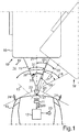
- An object 15 in the outer region 14 can thus be captured or imaged by means of the camera 11.
- the object 15 can be a trailer drawbar of a trailer 16.
- the trailer 16 can be coupled or attached to the motor vehicle 10 with its trailer drawbar via a trailer coupling 17 of the motor vehicle 10. While the motor vehicle 10 is traveling, the trailer 16 or generally the object 15 can execute a relative movement 18 around the trailer coupling 17, which represents a pivoting movement here.
- the trailer 16 is shown in two possible relative positions 19, 19 ', which can move from the relative movement 18.
- the respective current relative position 19, 19 ′ can be described as an articulation angle 20, which can be defined, for example, between a longitudinal axis 21 of the motor vehicle 10 and a longitudinal axis 22 of the object 15.
- the illustrated bend angle 20 is illustrated here for the relative position 19 '.
- the control device 12 can determine in the motor vehicle 10 which maximum articulation angle 23 is possible for the object 15.
- the maximum bending angle 23 is represented here by lines which show a respective edge of the object 15, which causes a collision 24 with the motor vehicle 10 when the maximum bending angle 23 is reached.
- the control device 12 can signal the maximum articulation angle 23 in the motor vehicle 10, as a result of which, for example, a driver assistance system can be configured such that it drives or maneuvers the motor vehicle 10 autonomously or automatically, that is to say without the intervention of a driver, and in this case that for the object 15 specific maximum bending angle 23 is taken into account in order to avoid the collision 24.
- Fig. 2 illustrates a method 25 that can be carried out by the control device 12 for determining the maximum articulation angle 13.
- the control device 12 can use the camera 11 to generate or record a camera image or briefly image 26 of the object 15 against a background 15 'at different measurement times.
- the background 15 ′ can be a driving surface or floor.
- Fig. 3 shows an example of an image 26 of how the object 15 could have been recorded or generated by means of the camera 11.
- This in Fig. 3 The image 26 shown can show the object 15 in the position 19. This image can be viewed as the first image in the sense of the invention.
- scan lines 27 can be defined or defined in the image 26.
- a shape of the scan lines 27 can correspond to the course of the pivoting movement 18, as a point on the object 15 would execute at the respective distance from the motor vehicle 10.
- the scan lines 27 can thus correspond to circle segments, with a corresponding distortion due to the perspective of the camera 11 and / or the optics of the camera 11 changing the shape accordingly.
- a corresponding corresponding scan line is also defined or defined in the other images 26 for each scan line 27.
- a course or a profile 29 which results along the scan line 27 can be determined for each scan line 27 for a predetermined image property 28.
- the image property can be, for example, a color value and / or a brightness value.
- An edge value of an edge detection 30 is preferably used, such as the edge detection 30 along the scan line 27 outputs or can generate, for example on the basis of the brightness values of the pixels of the image 26 along the scan line 27. For example, a difference between the brightness values of neighboring pixels can be calculated as edge detection.
- the profile 29 thus shows a course of the values E of the image property 28 along the scan line 27.
- the profile can be formed in each image 26, so that a correspondingly corresponding profile is also determined for each corresponding scan line of every other image 26. It is crucial here that during a rolling movement of the motor vehicle 10 in the profiles a respective object section or an object segment 31 (see Fig. 1 ) match in all profiles of the corresponding scan lines 27. Only their position along the respective scan line is different, depending on the respective position 19, 19 'of the object 15. In contrast, the background 15' changes due to the rolling movement in each image 26, so that the corresponding background sections or background segments look different in each profile or get lost.
- a respective displacement distance 33 can be added to the profile 29 of the image 26 (see Fig. 1 ) be determined.
- the shift distance indicates how far the corresponding profile of each other image 26 has to be shifted with respect to the profile 29 in order to obtain a maximum match.
- the displacement distance 33 can be carried out, for example, on the basis of a correlation, so that the maximum correlation results in the correlation maximum.
- a step S14 the profile 29 of each scan line 27 of the image 26 can be overlaid with the corresponding profile of each other image 26 shifted by the respective displacement distance 33.
- the overlay can be done, for example, by multiplying the profiles. An overlay profile 34 is thus created for each scan line 27.
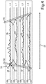
- Fig. 4 shows for four exemplary scan lines L0, L1, L2, L3, their position in Fig. 3 the resulting overlay profile 34 is illustrated.
- a reference pattern 36 can be determined on the basis of a predetermined delimitation criterion 35, which corresponds to the overlay profile, that is to say the object segment 31.
- the delimitation criterion 35 can, for example, provide threshold values 35 ′, the exceeding or falling below of which is signaled by the overlay profile 34 that it is the reference pattern 36 of the object 15.
- the threshold values 35 ' are here for an example in FIG Fig. 4 illustrated.
- control device 12 can then signal either the object boundaries 38 or a maximum articulation angle 23 calculated therefrom.
- the automatic detection of the maximum adjustable articulation angle 23 of a trailer 16 is thus made possible. This increases the dynamic range or the steering angle range for the driver as much as the current object 15 allows.
- a reference pattern 26 thus results overall for each scan line 27.
- This reference pattern 26 contains the information about the trailer geometry and thus the real extent of, for example, a trailer drawbar or generally an object 15. This allows the articulation angle 20 of the trailer 16 to be controlled so far that the Trailer drawbar with a safety distance to the motor vehicle can be regulated or guided.
- the driver can thus regulate significantly larger articulation angles 20 depending on his specific trailer and thus has a higher dynamic range when driving with the trailer 16.
Description
Die Erfindung betrifft ein Verfahren zum Ermitteln von Objektgrenzen eines Objekts in einem Außenbereich eines Kraftfahrzeugs. Das Objekt ist hierbei mit dem Kraftfahrzeug verbunden, aber relativ beweglich gelagert. Es kann sich beispielsweise um einen Anhänger handeln. Zu der Erfindung gehören auch eine Steuervorrichtung zum Durchführen des Verfahrens sowie ein Kraftfahrzeug mit der erfindungsgemäßen Steuervorrichtung.The invention relates to a method for determining object boundaries of an object in an outer region of a motor vehicle. The object is connected to the motor vehicle, but is mounted in a relatively movable manner. For example, it can be a trailer. The invention also includes a control device for carrying out the method and a motor vehicle with the control device according to the invention.
In einem Kraftfahrzeug kann ein Fahrerassistenzsystem bereitgestellt sein, welches einen Fahrer beim Führen des Kraftfahrzeugs unterstützen kann, während an das Kraftfahrzeug ein Anhänger angekuppelt ist. Für Kurvenfahrten (vorwärts und rückwärts) ist hierbei der maximal einstellbare Knickwinkel zwischen Kraftfahrzeug und Anhänger ein wichtiger Parameter für das Fahrerassistenzsystem, um eine Kollision oder ein Verkanten zwischen Anhänger und Kraftfahrzeug zu vermeiden. Bei heutigen Fahrerassistenzsystemen wird der Wert des Knickwinkels unabhängig von der realen Form der Anhängerdeichsel des Anhängers vorgegeben. Damit für eine Vielzahl von möglichen Formen stets sichergestellt ist, dass es zu keinem Verkanten kommt, muss eine möglichst breite Form der Deichsel angenommen werden. Dadurch ist aber der Fahrer vor allem bei einer schmalen Anhängerdeichsel in der Fahrdynamik eingeschränkt.A driver assistance system can be provided in a motor vehicle, which can assist a driver in driving the motor vehicle while a trailer is coupled to the motor vehicle. For cornering (forward and backward), the maximum adjustable articulation angle between the motor vehicle and the trailer is an important parameter for the driver assistance system in order to avoid a collision or tilting between the trailer and the motor vehicle. In today's driver assistance systems, the value of the articulation angle is specified regardless of the real shape of the trailer's drawbar. To ensure that a multitude of possible shapes always ensure that there is no tilting, the widest possible shape of the drawbar must be assumed. As a result, the driver is restricted in driving dynamics, especially with a narrow drawbar.
Aus der
Aus der
Aus der
Aus der
Das beschriebene Problem ist aber allgemeiner. Wann immer ein Objekt mit einem Kraftfahrzeug relativ beweglich verbunden ist, ist es vorteilhaft zu wissen, wo sich Objektgrenzen des Objekts befinden, um hieraus beispielsweise den maximal möglichen Knickwinkel zu ermitteln, bei welchem das Objekt mit seinen Objektgrenzen das Kraftfahrzeug berührt oder mit ihm kollidiert.
Aus der
Aus der
Der Erfindung liegt die Aufgabe zugrunde, bei einem Objekt, das in einem Außenbereich des Kraftfahrzeugs an diesem relativ beweglich angekuppelt oder angeordnet ist, dessen Objektgrenzen zu ermitteln.From the
From the
The problem described is more general. Whenever an object is connected to a motor vehicle in a relatively movable manner, it is advantageous to know where object boundaries of the object are located, in order to determine from this, for example, the maximum possible bending angle at which the object touches the motor vehicle or collides with it.
From the
From the
The object of the invention is to determine the object boundaries of an object which is coupled or arranged to the motor vehicle in a relatively movable manner in the outer region thereof.
Die Aufgabe wird durch die Gegenstände der unabhängigen Patentansprüche gelöst. Vorteilhafte Weiterbildungen der Erfindung sind durch die abhängigen Patentansprüche, die folgende Beschreibung sowie die Figuren beschrieben.The object is solved by the subject matter of the independent claims. Advantageous developments of the invention are described by the dependent claims, the following description and the figures.
Durch die Erfindung ist ein Verfahren zum Ermitteln von Objektgrenzen eines Objekts in einem Außenbereich eines Kraftfahrzeugs bereitgestellt. Das Verfahren geht davon aus, dass das das Objekt mit dem Kraftfahrzeug relativbeweglich verbunden ist. Durch eine Steuervorrichtung des Kraftfahrzeugs wird während einer Fahrt des Kraftfahrzeugs mittels einer Kamera zu zumindest zwei unterschiedlichen Messzeitpunkten jeweils ein Bild erzeugt. Das Bild zeigt das Objekt vor einem Hintergrund des Außenbereichs.The invention provides a method for determining object boundaries of an object in an outside area of a motor vehicle. The method assumes that the object is relatively movably connected to the motor vehicle. A control device of the motor vehicle generates an image during a journey of the motor vehicle using a camera at at least two different measuring times. The picture shows the object against a background of the outside area.
Durch die Steuervorrichtung wird in einem ersten der Bilder zumindest eine Scanlinie festgelegt. Eine andere Bezeichnung für Scanlinie ist auch Abtastlinie. Eine Scanlinie ist eine Linie, die über das Bild verläuft und hierdurch eine Folge von Pixeln festlegt, die auf der Scanlinie liegen. Zu jeder Scanlinie in jedem anderen Bild eine korrespondierende Scanlinie festgelegt. In jedem Bild werden also dieselben Scanlinien definiert, wobei eben eine Scanlinie des ersten Bilds mit jeweils einer Scanlinie jedes anderen Bilds korrespondiert, weshalb diese Scanlinien korrespondierende Scanlinien genannt sind.The control device defines at least one scan line in a first of the images. Another name for the scan line is the scan line. A scan line is a line that runs over the image and thereby defines a sequence of pixels that lie on the scan line. A corresponding scan line is defined for each scan line in every other image. The same scan lines are thus defined in each image, one scan line of the first image corresponding to one scan line of each other image, which is why these scan lines are called corresponding scan lines.
Zu jeder Scanlinie des ersten Bilds wird zu einer vorbestimmten Bildeigenschaft, beispielsweise der Pixelhelligkeit oder Pixelfarbe, ein sich entlang der Scanlinie ergebendes Profil ermittelt. Es werden also die jeweiligen Werte der Bildeigenschaft jedes Pixels entlang der Scanlinie aufgetragen, sodass sich als Verlauf das Profil ergibt. Zudem wird entlang der jeweils korrespondierenden Scanlinie jedes anderen Bilds ebenfalls ein sich ergebendes korrespondierendes Profil ermittelt. Man kann nun also das Profil jeder Scanlinie des ersten Bilds mit dem Profil der korrespondierenden Scanlinie jedes anderen Bilds vergleichen. Entsprechend wird zu dem Profil jeder Scanlinie des ersten Bilds eine jeweilige Verschiebeweite ermittelt, um welche das korrespondierende Profil jedes anderen Bilds bezüglich des Profils dieser Scanlinie verschoben werden muss, um eine maximale Übereinstimmung zu erhalten. Beispielsweise können hierzu das Profil und das korrespondierende Profil mittels einer Korrelation verglichen werden.For each scan line of the first image, a profile is determined along the scan line for a predetermined image property, for example the pixel brightness or pixel color. The respective values of the image property of each pixel are therefore plotted along the scan line, so that the profile results as the course. In addition, a resulting corresponding profile is also determined along the corresponding scan line of each other image. You can now compare the profile of each scan line of the first image with the profile of the corresponding scan line of every other image. Corresponding to the profile of each scan line of the first image, a respective shift distance is determined by which the corresponding profile of each other image with respect to the profile of this scan line must be shifted in order to obtain a maximum match. For example, the profile and the corresponding profile can be compared by means of a correlation.
Nun ist bekannt, wie weit sich das Profil aufgrund der relativen Bewegung des Objekts bezüglich des Kraftfahrzeugs entlang der Scanlinie verschoben hat. Dem Profil jeder Scanlinie des ersten Bilds wird das um die jeweilige Verschiebeweite verschobene korrespondierende Profil jedes anderen Bilds überlagert. Man gleicht also die Relativbewegungen des Objekts bezüglich des Kraftfahrzeugs aus, indem jedes korrespondierende Profil zurückverschoben wird, nämlich um die Verschiebeweite, sodass das korrespondierende Profil jedes anderen Bilds dem jeweiligen Profil jeder Scanlinie des ersten Bilds zu liegen kommt. Das Überlagern kann beispielsweise durch Multiplizieren der Profile geschehen. Insgesamt ergibt sich somit für jede Scanlinie ein Überlagerungsprofil, welches aus den überlagerten Profilen gebildet ist. Wichtig zu wissen ist nun, dass jedes Profil zwei Bestandteile oder Segmente aufweisen kann, nämlich ein Segment, das zum Objekt gehört, und Segmente, die zum Hintergrund gehören. Während einer Rollbewegung oder Fahrt des Kraftfahrzeugs ändert sich aber der Hintergrund ständig, während das mit dem Kraftfahrzeug verbundene Objekt gleich bleibt. Somit weist bei jedem Profil auch dasjenige Segment, das zum Objekt gehört, stets denselben oder einen ähnlichen Verlauf auf. Dagegen ändern sich die Segmente, die zum Hintergrund gehören, in jedem Profil. Durch die Überlagerung wird somit also jedes Segment, das zum Hintergrund gehört "herausgemittelt". Dagegen überlagern sich die Segmente, die zum Objekt gehören, konstruktiv, das heißt es bildet sich im Überlagerungsprofil das Muster oder der Verlauf aus, der für das Objekt charakteristisch ist. Die Segmente, die dem Hintergrund entsprechen, weisen dagegen einen Verlauf auf, der zum Beispiel mit jedem weiteren überlagerten Profil zu Null hin tendiert. Entsprechend wird in dem Überlagerungsprofil jeder Scanlinie auf Grundlagen eines vorbestimmten Abgrenzungskriteriums ein Referenzmuster ermittelt. Dieses Referenzmuster ist der sich im Segment des Objekts ergebende Verlauf des Profils. Jeweilige Grenzen des Referenzmusters, also der rechte Rand und der linke Rand oder der vordere Rand und hintere Rand, werden als die jeweiligen Objektgrenzen signalisiert. Somit kann man also vorhersagen, wie weit das Objekt relativ zum Kraftfahrzeug bewegt werden kann, bevor eine Objektgrenze des Objekts das Kraftfahrzeug berührt. Die hierfür nötige maximale Verschiebeweite kann eine entsprechende relative Bewegung des Objekts bezüglich des Kraftfahrzeugs umgewandelt werden. Bei einem Anhänger, bei welchem als Objekt die Anhängerdeichsel erkannt werden könnte, kann also zum Beispiel der maximale Knickwinkel auf diese Weise ermittelt werden.It is now known how far the profile has shifted along the scan line due to the relative movement of the object with respect to the motor vehicle. The profile of each scan line of the first image is overlaid with the corresponding profile of each other image, which has been shifted by the respective shifting distance. So one compensates the relative movements of the object with respect to the motor vehicle by each corresponding profile is shifted back, namely by the shifting distance, so that the corresponding profile of every other image comes to lie on the respective profile of each scan line of the first image. The overlay can be done, for example, by multiplying the profiles. Overall, there is an overlay profile for each scan line, which is formed from the overlaid profiles. It is important to know that each profile can have two components or segments, namely a segment that belongs to the object and segments that belong to the background. However, the background changes constantly during a rolling movement or travel of the motor vehicle, while the object connected to the motor vehicle remains the same. For each profile, the segment that belongs to the object always has the same or a similar course. In contrast, the segments belonging to the background change in each profile. The overlay thus "averages out" every segment that belongs to the background. On the other hand, the segments that belong to the object overlap constructively, that is, the pattern or course that is characteristic of the object is formed in the overlay profile. The segments that correspond to the background, on the other hand, have a course that tends to zero, for example, with each further superimposed profile. Accordingly, a reference pattern is determined in the overlay profile of each scan line based on a predetermined delimitation criterion. This reference pattern is the profile profile that results in the segment of the object. Respective boundaries of the reference pattern, that is to say the right edge and the left edge or the front edge and rear edge, are signaled as the respective object boundaries. It is thus possible to predict how far the object can be moved relative to the motor vehicle before an object boundary of the object touches the motor vehicle. The maximum displacement distance required for this can be converted into a corresponding relative movement of the object with respect to the motor vehicle. In the case of a trailer in which the trailer drawbar could be recognized as an object, the maximum articulation angle can be determined in this way, for example.
Durch die Erfindung ergibt sich der Vorteil, dass mittels des Verfahrens ohne Kenntnis der Geometrie des Objekts durch Beobachten den Profile der unterschiedlichen Bilder ermittelt werden kann, wie breit das Objekt ist oder welche Objektgrenzen das Objekt aufweist. Daraus kann dann ermittelt werden, welche relative Bewegung des Objekts bezüglich des Kraftfahrzeugs möglich ist, ohne dass es hierbei zu einer Kollision kommt.The advantage of the invention is that by means of the method, without knowing the geometry of the object, the profiles of the different images can be determined by observing how wide the object is or which object boundaries the object has. From this, it can then be determined which relative movement of the object with respect to the motor vehicle is possible without a collision occurring.
Die Erfindung sieht vor, dass das Überlagerungsprofil durch Addieren oder Multiplizieren der Profile gebildet wird. Hierdurch kommt es zu dem beschriebenen Herausmitteln derjenigen Anteile der Profile, die zum Hintergrund gehören.The invention provides that the overlay profile is formed by adding or multiplying the profiles. This results in the described averaging of those portions of the profiles that belong to the background.
Zu der Erfindung gehören auch Ausführungsformen, durch die sich zusätzliche Vorteile ergeben.The invention also includes embodiments which result in additional advantages.
Eine Ausführungsform sieht vor, dass die besagte Verschiebeweite der Profile mittels einer Korrelation ermittelt wird und hierbei die maximale Übereinstimmung, nach welcher gesucht wird, bei einem Korrelationsmaximum festgelegt wird. Hierdurch ergibt sich der Vorteil, das keine aufwändige Mustererkennung durchgeführt werden muss.One embodiment provides that the said displacement range of the profiles is determined by means of a correlation and the maximum match that is sought for is determined at a correlation maximum. This has the advantage that no complex pattern recognition has to be carried out.
Eine Ausführungsform sieht vor, dass das Abgrenzungskriterium zum Erkennen des Referenzmusters im Überlagerungsprofil einen Schwellenwertvergleich vorsieht. All diejenigen Anteile des Überlagerungsprofils, die auf einer Seite des Schwellenwerts liegen, werden dem Referenzmuster zugerechnet. Die übrigen Anteile des Überlagerungsprofils werden dem Hintergrund zugerechnet. Durch den Schwellenwertvergleich ist eine berechnungstechnisch einfaches Vorgehen beim Ermitteln des Referenzmusters vergeben.One embodiment provides that the delimitation criterion for recognizing the reference pattern in the overlay profile provides a threshold value comparison. All those parts of the overlay profile that are on one side of the threshold are assigned to the reference pattern. The remaining parts of the overlay profile are added to the background. By comparing the threshold values, a calculation-technically simple procedure for determining the reference pattern is assigned.
Eine Ausführungsform sieht vor, dass mittels der Kamera als der Hintergrund ein Fahruntergrund des Kraftfahrzeugs erfasst wird. Je näher der Hintergrund an der Kamera ist, desto größer ist die Veränderung bei einer Rollbewegung des Kraftfahrzeugs. Der Hintergrund ändert sich entsprechend bei einer Rollbewegung des Kraftfahrzeugs, sodass durch Überlagern der Profile eine entsprechend eindeutige Abgrenzung oder Segmentierung zwischen Objekt und Hintergrund ermöglicht ist.One embodiment provides that a driving surface of the motor vehicle is recorded as the background by means of the camera. The closer the background is to the camera, the greater the change when the motor vehicle rolls. The background changes accordingly when the motor vehicle rolls, so that a corresponding clear delimitation or segmentation between object and background is made possible by superimposing the profiles.
Eine Ausführungsform sieht vor, dass die vorbestimmte Bildeigenschaft, auf deren Grundlage die Profile gebildet werden, einen Farbwert und/oder einen Kontrastwert und/oder Helligkeitswert und/oder einen Kantendetektionswert eines Bildinhalts des Bildes umfasst. Es wird also zu jedem Pixel, das auf einer Scanlinie liegt, dessen Farbewert (zum Beispiel Rot oder Grün oder Blau) und/oder der Helligkeitswert und/oder ein Kontrastwert (Differenz der Helligkeitswerte zweier benachbarter Pixel) und/oder ein Kantendetektionswert, wie er durch einen Kantendetektionsfilter ermittelt werden kann, ermittelt. Es kann also beispielsweise als Profil ein Kantenprofil vorgesehen sein. Kantendetektionsfilter können dem Stand der Technik entnommen werden.One embodiment provides that the predetermined image property, on the basis of which the profiles are formed, comprises a color value and / or a contrast value and / or brightness value and / or an edge detection value of an image content of the image. Each pixel that lies on a scan line therefore has its color value (for example red or green or blue) and / or the brightness value and / or a contrast value (difference in the brightness values of two adjacent pixels) and / or an edge detection value as it is can be determined by an edge detection filter. For example, an edge profile can be provided as the profile. Edge detection filters can be found in the prior art.
Eine Ausführungsform sieht vor, dass die Scanlinien und die korrespondierenden Scanlinien einen Verlauf aufweisen, also eine Form oder Krümmung, welche jeweiligen Kurvenbahn entspricht, entlang welcher sich das Objekt aufgrund seiner relativbeweglichen Lagerung am Kraftfahrzeugs bewegen muss. Beispielsweise kann eine Anhängerdeichsel an einer Anhängerkupplung lediglich eine Schwenkbewegung oder Kreisbewegung ausführen. Entsprechend sind dann die Scanlinien als Kreissegmente ausgestaltet. Hierdurch ist sichergestellt, dass ein Bildinhalt, also das Objekt, insbesondere die Anhängerdeichsel, entlang der Scanlinie bewegt ist, wenn es eine Relativbewegung zwischen Objekt und Kraftfahrzeug gibt. Somit bildet sich das Referenzmuster in dem Überlagerungsprofil der Scanlinie heraus.One embodiment provides that the scan lines and the corresponding scan lines have a course, that is to say a shape or curvature which corresponds to the respective curved path along which the object has to move due to its relatively movable mounting on the motor vehicle. For example, a trailer drawbar on one Only perform a swivel or circular motion on the towbar. Accordingly, the scan lines are then designed as circle segments. This ensures that an image content, ie the object, in particular the trailer drawbar, is moved along the scan line if there is a relative movement between the object and the motor vehicle. The reference pattern is thus formed in the overlay profile of the scan line.
Eine Ausführungsform sieht vor, dass anhand der Objektgrenzen ein objektspezifischer maximaler Knickwinkel ermittelt wird, bei welchem das Objekt mit dem Kraftfahrzeug kollidiert oder verkantet. Somit kann ohne ursprüngliche Kenntnis der Form einer Anhängerdeichsel mittels des Verfahrens dennoch der maximal mögliche Knickwinkel für das spezifische Objekt, also zum Beispiel die spezifische Anhängerdeichsel, ermittelt werden.One embodiment provides that an object-specific maximum bending angle is determined on the basis of the object boundaries, at which the object collides or cant with the motor vehicle. Thus, without prior knowledge of the shape of a trailer drawbar, the method can still be used to determine the maximum possible articulation angle for the specific object, for example the specific trailer drawbar.
Eine Ausführungsform sieht vor, dass das Objekt eine Anhängerdeichsel eines von dem Kraftfahrzeug geschleppten Anhängers ist. Ein anderes mögliches Objekt wäre beispielsweise eine auswechselbare Baggerschaufel oder eine Abschleppstange.One embodiment provides that the object is a trailer drawbar of a trailer towed by the motor vehicle. Another possible object would be a replaceable excavator bucket or a tow bar.
Eine Ausführungsform sieht vor, dass die Referenzmuster der Scanlinien zu einer zweidimensionalen Karte oder Beschreibung des Objekts zusammengefasst werden. Hierzu werden die Referenzmuster zwischen den Scanlinien interpoliert. Somit erhält man zu jedem möglichen Punkt des Objekts aus der zweidimensionalen Karte eine Angabe der Oberflächenform des Objekts, wie sie durch die Referenzmuster beschrieben ist.One embodiment provides that the reference patterns of the scan lines are combined into a two-dimensional map or description of the object. For this purpose, the reference patterns are interpolated between the scan lines. Thus, for each possible point of the object, the surface shape of the object is obtained from the two-dimensional map, as described by the reference pattern.
Um das erfindungsgemäße Verfahren in einem Kraftfahrzeug durchzuführen, ist durch die Erfindung eine Steuervorrichtung für ein Kraftfahrzeug bereitgestellt. Die erfindungsgemäße Steuervorrichtung kann beispielsweise als ein Steuergerät des Kraftfahrzeugs ausgestaltet sein. Die Steuervorrichtung weist eine Recheneinrichtung auf, die dazu eingerichtet ist, eine Ausführungsform des erfindungsgemäßen Verfahrens durchzuführen. Die Steuervorrichtung kann hierzu zumindest einen Mikrocontroller und/oder zumindest einen Mikroprozessor umfassen. Zum Durchführen des Verfahrens kann ein Programmcode bereitgestellt sein, der dazu eingerichtet ist, bei Ausführen durch die Recheneinrichtung die Ausführungsform des erfindungsgemäßen Verfahrens durchzuführen. Der Programmcode kann in einem Datenspeicher der Recheneinrichtung gespeichert sein.In order to carry out the method according to the invention in a motor vehicle, the invention provides a control device for a motor vehicle. The control device according to the invention can be designed, for example, as a control unit of the motor vehicle. The control device has a computing device which is set up to carry out an embodiment of the method according to the invention. For this purpose, the control device can comprise at least one microcontroller and / or at least one microprocessor. To carry out the method, a program code can be provided which is set up to carry out the embodiment of the method according to the invention when it is executed by the computing device. The program code can be stored in a data memory of the computing device.
Schließlich gehört zu der Erfindung auch ein Kraftfahrzeug mit zumindest einer Kamera zum Erfassen eines Außenbereichs des Kraftfahrzeugs und mit einer Ausführungsform der erfindungsgemäßen Steuervorrichtung. Die Steuervorrichtung ist mit der zumindest einen Kamera gekoppelt. Das erfindungsgemäße Kraftfahrzeug ist bevorzugt als Kraftwagen, insbesondere als Personenkraftwagen oder Lastkraftwagen, ausgestaltet.Finally, the invention also includes a motor vehicle with at least one camera for capturing an outer region of the motor vehicle and with an embodiment of the control device according to the invention. The control device is with the at least one Camera paired. The motor vehicle according to the invention is preferably designed as a motor vehicle, in particular as a passenger car or truck.
Zu der Erfindung gehören auch die Kombinationen der beschriebenen Ausführungsformen. Im Folgenden ist ein Ausführungsbeispiel der Erfindung beschrieben. Hierzu zeigt:
- Fig. 1
- eine schematische Darstellung einer Ausführungsform des erfindungsgemäßen Kraftfahrzeugs;
- Fig. 2
- ein Flussschaudiagramm einer Ausführungsform des erfindungsgemäßen Verfahrens;
- Fig. 3
- eine schematische Darstellung eines Bildes, das von einer Kamera des Kraftfahrzeugs erzeugt wurde; und
- Fig. 4
- ein Diagramm mit Überlagerungsprofilen.
In den Figuren sind funktionsgleiche Elemente jeweils mit denselben Bezugszeichen versehen.
- Fig. 1
- a schematic representation of an embodiment of the motor vehicle according to the invention;
- Fig. 2
- a flow chart diagram of an embodiment of the method according to the invention;
- Fig. 3
- is a schematic representation of an image generated by a camera of the motor vehicle; and
- Fig. 4
- a diagram with overlay profiles.
In the figures, elements with the same function are each provided with the same reference symbols.
Mittels der Kamera 11 kann somit ein Objekt 15 im Außenbereich 14 erfasst oder abgebildet werden. In dem dargestellten Beispiel kann es sich bei dem Objekt 15 um eine Anhängerdeichsel eines Anhängers 16 handeln. Der Anhänger 16 kann mit seiner Anhängerdeichsel über eine Anhängerkupplung 17 des Kraftfahrzeugs 10 an das Kraftfahrzeug 10 angekuppelt oder angehängt sein. Während eines Fahrt des Kraftfahrzeugs 10 kann somit der Anhänger 16 oder allgemein das Objekt 15 um die Anhängerkupplung 17 herum eine Relativbewegung 18 ausführen, die hier ein Schwenkbewegung darstellt. Der Anhänger 16 ist in zwei möglichen Relativpositionen 19, 19' dargestellt, die sich aus der Relativbewegung 18 bewegen können. Die jeweilige aktuelle Relativposition 19, 19' kann als ein Knickwinkel 20 beschrieben sein, der beispielsweise zwischen einer Längsachse 21 des Kraftfahrzeugs 10 und einer Längsachse 22 des Objekts 15 definiert sein kann. Der dargestellte Knickwinkel 20 ist hier für die Relativposition 19' veranschaulicht.
Die Steuervorrichtung 12 kann bei dem Kraftfahrzeug 10 ermitteln, welcher maximale Knickwinkel 23 für das Objekt 15 möglich ist. Der maximale Knickwinkel 23 ist hier durch Linien repräsentiert, welche eine jeweilige Kante des Objekts 15 zeigen, die mit dem Kraftfahrzeug 10 bei Erreichen des maximalen Knickwinkels 23 eine Kollision 24 mit dem Kraftfahrzeug 10 verursacht. Die Steuervorrichtung 12 kann den maximalen Knickwinkel 23 in dem Kraftfahrzeug 10 signalisieren, wodurch beispielsweise ein Fahrerassistenzsystem dahingehend konfiguriert werden kann, dass es das Kraftfahrzeug 10 autonom oder automatisiert, das heißt ohne ein Zutun eines Fahrers, führt oder manövriert und hierbei den für das Objekt 15 spezifischen maximalen Knickwinkel 23 berücksichtigt, um die Kollision 24 zu vermeiden.An
The
In einem Schritt S10 kann während einer Fahrt des Kraftfahrzeugs 10, wenn sich die Relativbewegung 18 ergibt, durch die Steuervorrichtung 12 mittels der Kamera 11 zu unterschiedlichen Messzeitpunkten jeweils ein Kamerabild oder kurz Bild 26 des Objekts 15 vor einem Hintergrund 15' erzeugt oder aufgenommen werden. Der Hintergrund 15' kann bei der dargestellten Ausrichtung des Erfassungsbereichs 13 der Kamera 11 ein Fahruntergrund oder Boden sein.In a step S10, while the motor vehicle 10 is traveling, if the
Für die weiteren Erläuterungen des Verfahrens 25 wird zusätzlich auf
In einem Schritt S11 können in dem Bild 26 Scanlinien 27 definiert oder festgelegt werden. Eine Form der Scanlinien 27 kann dem Verlauf der Schwenkbewegung 18 entsprechen, wie ihn im jeweiligen Abstand zum Kraftfahrzeug 10 ein Punkt auf dem Objekt 15 ausführen würde. Die Scanlinien 27 können also Kreissegmenten entsprechen, wobei eine entsprechende Verzerrung durch die Perspektive der Kamera 11 und/oder der Optik der Kamera 11 die Form entsprechend ändert. Auch in den übrigen Bildern 26 wird für jede Scanlinie 27 eine jeweils korrespondierende Scanlinie definiert oder festgelegt.In a step S11,
In einem Schritt S12 kann zu jeder Scanlinie 27 zu einer vorbestimmten Bildeigenschaft 28 ein sich entlang der Scanlinie 27 ergebender Verlauf oder ein sich ergebendes Profil 29 ermittelt werden. Bei der Bildeigenschaft kann es sich beispielsweise um eine Farbwert und/oder einen Helligkeitswert handeln. Bevorzugt wird ein Kantenwert einer Kantendetektion 30 verwendet, wie ihn die Kantendetektion 30 entlang der Scanlinie 27 beispielsweise auf der Grundlage der Helligkeitswerte der Pixel des Bilds 26 entlang der Scanlinie 27 ausgibt oder erzeugen kann. Beispielsweise kann als Kantendetektion eine Differenz der Helligkeitswerte benachbarter Pixel berechnet werden.In step S12, a course or a
Das Profil 29 zeigt somit einen Verlauf der Werte E der Bildeigenschaft 28 entlang der Scanlinie 27. Das Bilden des Profils kann in jedem Bild 26 durchgeführt werden, sodass zu jeder korrespondierenden Scanlinie jedes übrigen Bilds 26 ebenfalls ein entsprechend korrespondierendes Profil ermittelt wird. Entscheidend hierbei ist, dass während einer Rollbewegung des Kraftfahrzeugs 10 in den Profilen ein jeweiliger Objektabschnitt oder ein Objektsegment 31 (siehe
In einem Schritt S13 kann zu dem Profil 29 des Bilds 26 eine jeweilige Verschiebeweite 33 (siehe
In einem Schritt S14 kann dem Profil 29 jeder Scanlinie 27 des Bilds 26 das um die jeweilige Verschiebeweite 33 verschobene korrespondierende Profil jedes anderen Bilds 26 überlagert werden. Die Überlagerung kann beispielsweise mittels einer Multiplikation der Profile erfolgen. Es entsteht somit für jede Scanlinie 27 ein Überlagerungsprofil 34.In a step S14, the
Anhand der jeweiligen Grenzen 37 des Referenzmusters 36 jeder Scanlinie 27 können somit jeweilige Objektgrenzen 38 ermittelt werden. Es können durch die Steuervorrichtung 12 dann entweder die Objektgrenzen 38 oder ein daraus berechneter maximaler Knickwinkel 23 signalisiert werden.On the basis of the
Somit ist die automatische Erkennung des maximal einstellbaren Knickwinkels 23 eines Anhängers 16 ermöglicht. Damit erhöht sich der Dynamikbereich oder der Lenkwinkelbereich für den Fahrer soweit, wie es das aktuelle Objekt 15 zulässt.The automatic detection of the maximum
Durch Bilden von Profilen, beispielsweise mittels einer Kantenfunktion, die über der Zeit verfolgt werden, ergibt sich somit insgesamt für jede Scanlinie 27 ein Referenzmuster 26. Dieses Referenzmuster 26 beinhaltet die Information über die Anhängergeometrie und damit die reale Ausdehnung beispielsweise einer Anhängerdeichsel oder allgemein eines Objekts 15. Dadurch lässt sich der Knickwinkel 20 des Anhängers 16 soweit steuern, dass die Anhängerdeichsel mit einem Sicherheitsabstand zum Kraftfahrzeug geregelt oder geführt werden kann.By forming profiles, for example by means of an edge function, which are tracked over time, a
Der Fahrer kann somit abhängig von seinem spezifischen Anhänger wesentlich größere Knickwinkel 20 einregeln und hat somit eine höhere Dynamik beim Fahren mit dem Anhänger 16.The driver can thus regulate significantly larger articulation angles 20 depending on his specific trailer and thus has a higher dynamic range when driving with the
Insgesamt zeigt das Beispiel, wie auf der Grundlage der Erfindung eine optische Erkennung eines maximalen Knickwinkels eines Anhängers ermöglicht ist.Overall, the example shows how an optical detection of a maximum articulation angle of a trailer is made possible on the basis of the invention.
- 1010th
- KraftfahrzeugMotor vehicle
- 1111
- Kameracamera
- 1212th
- SteuervorrichtungControl device
- 1313
- ErfassungsbereichDetection area
- 1414
- AußenbereichOutdoor area
- 1515
- Objektobject
- 15'15 '
- Hintergrundbackground
- 1616
- Anhängerpendant
- 1717th
- Anhängerkupplungtrailer hitch
- 1818th
- RelativbewegungRelative motion
- 1919th
- Stellungposition
- 19'19 '
- Stellungposition
- 2020
- KnickwinkelKink angle
- 2121
- LängsachseLongitudinal axis
- 2222
- MittelachseCentral axis
- 2323
- Maximaler Knickwinkel (symbolisch)Maximum kink angle (symbolic)
- 2424th
- Kollisioncollision
- 2525th
- VerfahrenProcedure
- 2626
- Bildimage
- 2727
- ScanlinieScan line
- 2828
- BildeigenschaftImage property
- 2929
- Profilprofile
- 3030th
- KantendetektionEdge detection
- 3131
- ObjektsegmentObject segment
- 3333
- VerschiebweiteDisplacement
- 3434
- ÜberlagerungsprofilOverlay profile
- 3535
- AbgrenzungskriteriumDelimitation criterion
- 35'35 '
- SchwellenwertThreshold
- 3636
- ReferenzmusterReference pattern
- 3737
- Grenzeborder
- 3838
- ObjektgrenzeObject boundary
- EE
- Wert der BildeigenschaftValue of the image property
- L0, L1L0, L1
- ScanlinieScan line
- L2, L3L2, L3
- ScanlinieScan line
Claims (11)
- Method (25) for determining object boundaries (38) of an object (15) in an external area (14) of a motor vehicle (10), wherein the object (15) is connected to the vehicle (10) in a relatively movable fashion, and in each case an image (26), which shows the object (15) against a background (15') of the external area (14), is generated by a control device (12) of the motor vehicle (10) by means of a camera (11) at at least two different measuring times while the motor vehicle (10) is travelling, and- in a first of the images (26) at least one scanning line (27) is defined, in each of the other images (26) a corresponding scanning line is defined for each scanning line (27) and- for each scanning line (26) of the first image (26) a profile (29) which occurs along the scanning line (27) is determined for a predetermined image property (28), and a resulting corresponding profile is determined along the respectively corresponding scanning line of each other image (26), and- for the profile (29) of each scanning line (27) of the first image a respective shift distance (33) is determined, by which distance the corresponding profile of each other image (26) has to be shifted with respect to the profile (29) in order to obtain maximum correspondence,
characterized in that- the profile (29) of each scanning line (27) of the first image (26) has superimposed on it the corresponding profile, shifted by the respective shifting distance (33), of each other image (26), with the result that a superimposition profile (34) is produced for each scanning line (27), wherein the superimposition profile (34) is formed by adding or multiplying the profiles (29), and- in the superimposition profile (34) of each scanning line (27), a reference pattern (36) is determined on the basis of a predetermined delimitation criterion (35), and respective boundaries (37) of the reference pattern (36) are signalled as the respective object boundaries (38). - Method (25) according to Claim 1, wherein the shifting distance (33) is determined by means of correlation, and in the process the maximum correspondence for a correlation maximum is defined.
- Method (25) according to one of the preceding claims, wherein the delimitation criterion (35) provides a threshold value comparison.
- Method (25) according to one of the preceding claims, wherein a driving underlying surface of the motor vehicle (10) is captured as the background (15') by means of the camera (11).
- Method (25) according to one of the preceding claims, wherein the predetermined image property (28) comprises a colour value and/or brightness value and/or contrast value and/or an edge detection value of image contents of the respective image (26).
- Method (25) according to one of the preceding claims, wherein the scanning lines (27) and the corresponding scanning lines have a profile which corresponds to a respective curved path along which the object (15) must move when there is a relative movement (18), owing to the relatively movable support of said object (15) on the motor vehicle (10).
- Method (25) according to one of the preceding claims, wherein an object-specific maximum bend angle (23), at which the object (15) collides with the motor vehicle (10), is determined on the basis of the object boundaries (38).
- Method according to one of the preceding claims, wherein the object (15) is a trailer drawbar of a trailer (16) which is towed by the motor vehicle (10).
- Method according to one of the preceding claims, wherein the reference patterns (34) of the scanning lines (27) are combined to form a two-dimensional map of the object (15).
- Control device (12) for a motor vehicle (10), wherein the control device (12) has a computing apparatus which is configured to carry out a method according to one of the preceding claims.
- Motor vehicle (10) having at least one camera (11) for capturing an external area (14) of the motor vehicle (10) and having a control device (12) according to Claim 10, wherein the control device (12) is coupled to the at least one camera (11).
Applications Claiming Priority (1)
| Application Number | Priority Date | Filing Date | Title |
|---|---|---|---|
| DE102017219123.6A DE102017219123B4 (en) | 2017-10-25 | 2017-10-25 | Method for determining object boundaries of an object in an exterior area of a motor vehicle, and control device and motor vehicle |
Publications (2)
| Publication Number | Publication Date |
|---|---|
| EP3476696A1 EP3476696A1 (en) | 2019-05-01 |
| EP3476696B1 true EP3476696B1 (en) | 2020-07-15 |
Family
ID=63579215
Family Applications (1)
| Application Number | Title | Priority Date | Filing Date |
|---|---|---|---|
| EP18194311.9A Active EP3476696B1 (en) | 2017-10-25 | 2018-09-13 | Method for determining object boundaries of an object in an external area of a motor vehicle and control device and motor vehicle |
Country Status (3)
| Country | Link |
|---|---|
| US (1) | US10836224B2 (en) |
| EP (1) | EP3476696B1 (en) |
| DE (1) | DE102017219123B4 (en) |
Families Citing this family (2)
| Publication number | Priority date | Publication date | Assignee | Title |
|---|---|---|---|---|
| DE102017219119A1 (en) * | 2017-10-25 | 2019-04-25 | Volkswagen Aktiengesellschaft | Method for detecting the shape of an object in an exterior of a motor vehicle and motor vehicle |
| DE102019110018B4 (en) * | 2019-04-16 | 2023-09-21 | Valeo Schalter Und Sensoren Gmbh | Collision avoidance method, system, in-vehicle system, towing vehicle and signal |
Family Cites Families (14)
| Publication number | Priority date | Publication date | Assignee | Title |
|---|---|---|---|---|
| DE102004050149A1 (en) | 2004-10-15 | 2006-04-20 | Daimlerchrysler Ag | Drawbar and trailer angle determining method, involves ascertaining drawbar and trailer`s characteristic edges and lines from video stream of sensor e.g. video camera, and determining angles from geometrical conditions of characteristic |
| DE102008045436A1 (en) | 2008-09-02 | 2010-03-04 | Volkswagen Ag | Method for determining inclination angle between tractor and trailer for e.g. lorry, involves automatically determining inclination angle based on comparison of detected image with reference images and reference image inclination angle |
| US9937953B2 (en) * | 2011-04-19 | 2018-04-10 | Ford Global Technologies, Llc | Trailer backup offset determination |
| US9238483B2 (en) * | 2011-04-19 | 2016-01-19 | Ford Global Technologies, Llc | Trailer backup assist system with trajectory planner for multiple waypoints |
| US9723274B2 (en) * | 2011-04-19 | 2017-08-01 | Ford Global Technologies, Llc | System and method for adjusting an image capture setting |
| DE102011101990B3 (en) * | 2011-05-19 | 2012-10-18 | Volkswagen Aktiengesellschaft | Method for determining relative drawbar angle in articulated train, involves coupling tensile unit and trailer by rotatably mounted shaft and two-dimensional image is captured by unit for imaging two-dimensional image |
| DE102011104256A1 (en) | 2011-06-15 | 2012-07-26 | Audi Ag | Bend angle sensor for driver assistance system of motor car formed for drawing trailer with drawbar, has computing unit comparing image features with current image to determine bend angle, where features are stored in calibration phase |
| US9694850B2 (en) * | 2011-07-18 | 2017-07-04 | Daniel Robert Shepard | Trailer backing up device and table based method |
| DE102011113191B4 (en) | 2011-09-10 | 2022-10-06 | Volkswagen Aktiengesellschaft | Method and device for determining an articulation angle between a vehicle and a trailer |
| DE102014223141B4 (en) * | 2014-11-13 | 2019-06-19 | Volkswagen Aktiengesellschaft | Determining a position of a trailer hitch head |
| DE102015201586A1 (en) * | 2015-01-29 | 2016-08-04 | Volkswagen Aktiengesellschaft | Method and device for recognizing a trailer |
| US10017115B2 (en) * | 2015-11-11 | 2018-07-10 | Ford Global Technologies, Llc | Trailer monitoring system and method |
| US9981690B2 (en) * | 2016-04-13 | 2018-05-29 | Ford Global Technologies, Llc | Target-based trailer backup collision mitigation |
| US10766525B2 (en) * | 2016-07-01 | 2020-09-08 | Ford Global Technologies, Llc | Enhanced yaw rate trailer angle detection initialization |
-
2017
- 2017-10-25 DE DE102017219123.6A patent/DE102017219123B4/en not_active Expired - Fee Related
-
2018
- 2018-09-13 EP EP18194311.9A patent/EP3476696B1/en active Active
- 2018-10-16 US US16/161,244 patent/US10836224B2/en active Active
Non-Patent Citations (1)
| Title |
|---|
| None * |
Also Published As
| Publication number | Publication date |
|---|---|
| DE102017219123B4 (en) | 2022-12-22 |
| DE102017219123A1 (en) | 2019-04-25 |
| US20190118594A1 (en) | 2019-04-25 |
| EP3476696A1 (en) | 2019-05-01 |
| US10836224B2 (en) | 2020-11-17 |
Similar Documents
| Publication | Publication Date | Title |
|---|---|---|
| EP3501897B1 (en) | Vision system for detecting the surroundings of a vehicle | |
| EP2987663B1 (en) | Driver assistance system for a commercial vehicle trailer assembly and method for performing a coupling procedure | |
| EP3024700B1 (en) | Method and device for reproducing a lateral and/or rear surrounding area of a vehicle | |
| DE10109350B4 (en) | Assistance device for reverse parking a vehicle in series | |
| EP3219533B1 (en) | Viewing system for a motor vehicle, in particular a commercial vehicle | |
| EP2484558B1 (en) | Display device for fields of vision of a commercial vehicle | |
| DE102011104256A1 (en) | Bend angle sensor for driver assistance system of motor car formed for drawing trailer with drawbar, has computing unit comparing image features with current image to determine bend angle, where features are stored in calibration phase | |
| EP3012154B1 (en) | Method and device to support a driver of a vehicle combination, in particular a commercial vehicle combination | |
| DE102016011324A1 (en) | A method of controlling a towing vehicle as it approaches and hitches to a trailer vehicle | |
| DE19947766A1 (en) | Device for monitoring the surroundings of a parking vehicle | |
| EP3157786A1 (en) | Vehicle with surroundings-monitoring device and method for operating such a monitoring device | |
| DE102011113191B4 (en) | Method and device for determining an articulation angle between a vehicle and a trailer | |
| EP3284649B1 (en) | Driver assistance for parking a motor vehicle and a trailer by means of virtual sensors | |
| EP3477249B1 (en) | Method for shape recognition of an object in an external area of a motor vehicle and motor vehicle | |
| EP3476696B1 (en) | Method for determining object boundaries of an object in an external area of a motor vehicle and control device and motor vehicle | |
| DE102016115313A1 (en) | Method for supporting a driver of a team, driver assistance system and team | |
| DE102018005118A1 (en) | Method for determining a kink angle | |
| DE102017008816A1 (en) | Ausparkassistent | |
| DE10297590B4 (en) | Driving assistance system, image output device and camera equipped bar | |
| DE102014218995A1 (en) | Method and device for bird-view display of a vehicle combination and retrofittable camera | |
| DE102018205694B3 (en) | System and method for detecting an environment of a vehicle, vehicle with a system for environment detection and method for emergency braking of a vehicle | |
| WO2012019931A1 (en) | Method for displaying images on a display device in a motor vehicle, driver assistance system, and motor vehicle | |
| EP3743311B1 (en) | Method and device for operating a video monitoring system for a motor vehicle | |
| EP3833576A1 (en) | Camera monitoring system | |
| DE102016117401B4 (en) | Method and device for imaging a trailer with boundary markings |
Legal Events
| Date | Code | Title | Description |
|---|---|---|---|
| PUAI | Public reference made under article 153(3) epc to a published international application that has entered the european phase |
Free format text: ORIGINAL CODE: 0009012 |
|
| STAA | Information on the status of an ep patent application or granted ep patent |
Free format text: STATUS: THE APPLICATION HAS BEEN PUBLISHED |
|
| AK | Designated contracting states |
Kind code of ref document: A1 Designated state(s): AL AT BE BG CH CY CZ DE DK EE ES FI FR GB GR HR HU IE IS IT LI LT LU LV MC MK MT NL NO PL PT RO RS SE SI SK SM TR |
|
| AX | Request for extension of the european patent |
Extension state: BA ME |
|
| STAA | Information on the status of an ep patent application or granted ep patent |
Free format text: STATUS: REQUEST FOR EXAMINATION WAS MADE |
|
| 17P | Request for examination filed |
Effective date: 20191104 |
|
| RBV | Designated contracting states (corrected) |
Designated state(s): AL AT BE BG CH CY CZ DE DK EE ES FI FR GB GR HR HU IE IS IT LI LT LU LV MC MK MT NL NO PL PT RO RS SE SI SK SM TR |
|
| GRAP | Despatch of communication of intention to grant a patent |
Free format text: ORIGINAL CODE: EPIDOSNIGR1 |
|
| STAA | Information on the status of an ep patent application or granted ep patent |
Free format text: STATUS: GRANT OF PATENT IS INTENDED |
|
| RIC1 | Information provided on ipc code assigned before grant |
Ipc: B62D 13/06 20060101AFI20200319BHEP Ipc: G06K 9/00 20060101ALI20200319BHEP Ipc: B60D 1/62 20060101ALI20200319BHEP Ipc: B60D 1/24 20060101ALI20200319BHEP Ipc: B60D 1/30 20060101ALI20200319BHEP |
|
| INTG | Intention to grant announced |
Effective date: 20200401 |
|
| GRAS | Grant fee paid |
Free format text: ORIGINAL CODE: EPIDOSNIGR3 |
|
| GRAA | (expected) grant |
Free format text: ORIGINAL CODE: 0009210 |
|
| STAA | Information on the status of an ep patent application or granted ep patent |
Free format text: STATUS: THE PATENT HAS BEEN GRANTED |
|
| AK | Designated contracting states |
Kind code of ref document: B1 Designated state(s): AL AT BE BG CH CY CZ DE DK EE ES FI FR GB GR HR HU IE IS IT LI LT LU LV MC MK MT NL NO PL PT RO RS SE SI SK SM TR |
|
| REG | Reference to a national code |
Ref country code: CH Ref legal event code: EP Ref country code: GB Ref legal event code: FG4D Free format text: NOT ENGLISH |
|
| REG | Reference to a national code |
Ref country code: DE Ref legal event code: R096 Ref document number: 502018001898 Country of ref document: DE |
|
| REG | Reference to a national code |
Ref country code: IE Ref legal event code: FG4D Free format text: LANGUAGE OF EP DOCUMENT: GERMAN |
|
| REG | Reference to a national code |
Ref country code: AT Ref legal event code: REF Ref document number: 1290734 Country of ref document: AT Kind code of ref document: T Effective date: 20200815 |
|
| REG | Reference to a national code |
Ref country code: LT Ref legal event code: MG4D |
|
| REG | Reference to a national code |
Ref country code: NL Ref legal event code: MP Effective date: 20200715 |
|
| PG25 | Lapsed in a contracting state [announced via postgrant information from national office to epo] |
Ref country code: FI Free format text: LAPSE BECAUSE OF FAILURE TO SUBMIT A TRANSLATION OF THE DESCRIPTION OR TO PAY THE FEE WITHIN THE PRESCRIBED TIME-LIMIT Effective date: 20200715 Ref country code: NO Free format text: LAPSE BECAUSE OF FAILURE TO SUBMIT A TRANSLATION OF THE DESCRIPTION OR TO PAY THE FEE WITHIN THE PRESCRIBED TIME-LIMIT Effective date: 20201015 Ref country code: BG Free format text: LAPSE BECAUSE OF FAILURE TO SUBMIT A TRANSLATION OF THE DESCRIPTION OR TO PAY THE FEE WITHIN THE PRESCRIBED TIME-LIMIT Effective date: 20201015 Ref country code: SE Free format text: LAPSE BECAUSE OF FAILURE TO SUBMIT A TRANSLATION OF THE DESCRIPTION OR TO PAY THE FEE WITHIN THE PRESCRIBED TIME-LIMIT Effective date: 20200715 Ref country code: GR Free format text: LAPSE BECAUSE OF FAILURE TO SUBMIT A TRANSLATION OF THE DESCRIPTION OR TO PAY THE FEE WITHIN THE PRESCRIBED TIME-LIMIT Effective date: 20201016 Ref country code: PT Free format text: LAPSE BECAUSE OF FAILURE TO SUBMIT A TRANSLATION OF THE DESCRIPTION OR TO PAY THE FEE WITHIN THE PRESCRIBED TIME-LIMIT Effective date: 20201116 Ref country code: ES Free format text: LAPSE BECAUSE OF FAILURE TO SUBMIT A TRANSLATION OF THE DESCRIPTION OR TO PAY THE FEE WITHIN THE PRESCRIBED TIME-LIMIT Effective date: 20200715 Ref country code: LT Free format text: LAPSE BECAUSE OF FAILURE TO SUBMIT A TRANSLATION OF THE DESCRIPTION OR TO PAY THE FEE WITHIN THE PRESCRIBED TIME-LIMIT Effective date: 20200715 Ref country code: HR Free format text: LAPSE BECAUSE OF FAILURE TO SUBMIT A TRANSLATION OF THE DESCRIPTION OR TO PAY THE FEE WITHIN THE PRESCRIBED TIME-LIMIT Effective date: 20200715 |
|
| PG25 | Lapsed in a contracting state [announced via postgrant information from national office to epo] |
Ref country code: PL Free format text: LAPSE BECAUSE OF FAILURE TO SUBMIT A TRANSLATION OF THE DESCRIPTION OR TO PAY THE FEE WITHIN THE PRESCRIBED TIME-LIMIT Effective date: 20200715 Ref country code: LV Free format text: LAPSE BECAUSE OF FAILURE TO SUBMIT A TRANSLATION OF THE DESCRIPTION OR TO PAY THE FEE WITHIN THE PRESCRIBED TIME-LIMIT Effective date: 20200715 Ref country code: RS Free format text: LAPSE BECAUSE OF FAILURE TO SUBMIT A TRANSLATION OF THE DESCRIPTION OR TO PAY THE FEE WITHIN THE PRESCRIBED TIME-LIMIT Effective date: 20200715 Ref country code: IS Free format text: LAPSE BECAUSE OF FAILURE TO SUBMIT A TRANSLATION OF THE DESCRIPTION OR TO PAY THE FEE WITHIN THE PRESCRIBED TIME-LIMIT Effective date: 20201115 |
|
| PG25 | Lapsed in a contracting state [announced via postgrant information from national office to epo] |
Ref country code: NL Free format text: LAPSE BECAUSE OF FAILURE TO SUBMIT A TRANSLATION OF THE DESCRIPTION OR TO PAY THE FEE WITHIN THE PRESCRIBED TIME-LIMIT Effective date: 20200715 |
|
| REG | Reference to a national code |
Ref country code: DE Ref legal event code: R097 Ref document number: 502018001898 Country of ref document: DE |
|
| PG25 | Lapsed in a contracting state [announced via postgrant information from national office to epo] |
Ref country code: SM Free format text: LAPSE BECAUSE OF FAILURE TO SUBMIT A TRANSLATION OF THE DESCRIPTION OR TO PAY THE FEE WITHIN THE PRESCRIBED TIME-LIMIT Effective date: 20200715 Ref country code: IT Free format text: LAPSE BECAUSE OF FAILURE TO SUBMIT A TRANSLATION OF THE DESCRIPTION OR TO PAY THE FEE WITHIN THE PRESCRIBED TIME-LIMIT Effective date: 20200715 Ref country code: EE Free format text: LAPSE BECAUSE OF FAILURE TO SUBMIT A TRANSLATION OF THE DESCRIPTION OR TO PAY THE FEE WITHIN THE PRESCRIBED TIME-LIMIT Effective date: 20200715 Ref country code: CZ Free format text: LAPSE BECAUSE OF FAILURE TO SUBMIT A TRANSLATION OF THE DESCRIPTION OR TO PAY THE FEE WITHIN THE PRESCRIBED TIME-LIMIT Effective date: 20200715 Ref country code: DK Free format text: LAPSE BECAUSE OF FAILURE TO SUBMIT A TRANSLATION OF THE DESCRIPTION OR TO PAY THE FEE WITHIN THE PRESCRIBED TIME-LIMIT Effective date: 20200715 Ref country code: RO Free format text: LAPSE BECAUSE OF FAILURE TO SUBMIT A TRANSLATION OF THE DESCRIPTION OR TO PAY THE FEE WITHIN THE PRESCRIBED TIME-LIMIT Effective date: 20200715 |
|
| PLBE | No opposition filed within time limit |
Free format text: ORIGINAL CODE: 0009261 |
|
| STAA | Information on the status of an ep patent application or granted ep patent |
Free format text: STATUS: NO OPPOSITION FILED WITHIN TIME LIMIT |
|
| PG25 | Lapsed in a contracting state [announced via postgrant information from national office to epo] |
Ref country code: AL Free format text: LAPSE BECAUSE OF FAILURE TO SUBMIT A TRANSLATION OF THE DESCRIPTION OR TO PAY THE FEE WITHIN THE PRESCRIBED TIME-LIMIT Effective date: 20200715 |
|
| REG | Reference to a national code |
Ref country code: BE Ref legal event code: MM Effective date: 20200930 |
|
| 26N | No opposition filed |
Effective date: 20210416 |
|
| PG25 | Lapsed in a contracting state [announced via postgrant information from national office to epo] |
Ref country code: SK Free format text: LAPSE BECAUSE OF FAILURE TO SUBMIT A TRANSLATION OF THE DESCRIPTION OR TO PAY THE FEE WITHIN THE PRESCRIBED TIME-LIMIT Effective date: 20200715 Ref country code: LU Free format text: LAPSE BECAUSE OF NON-PAYMENT OF DUE FEES Effective date: 20200913 |
|
| PG25 | Lapsed in a contracting state [announced via postgrant information from national office to epo] |
Ref country code: BE Free format text: LAPSE BECAUSE OF NON-PAYMENT OF DUE FEES Effective date: 20200930 Ref country code: SI Free format text: LAPSE BECAUSE OF FAILURE TO SUBMIT A TRANSLATION OF THE DESCRIPTION OR TO PAY THE FEE WITHIN THE PRESCRIBED TIME-LIMIT Effective date: 20200715 Ref country code: IE Free format text: LAPSE BECAUSE OF NON-PAYMENT OF DUE FEES Effective date: 20200913 |
|
| REG | Reference to a national code |
Ref country code: CH Ref legal event code: PL |
|
| PG25 | Lapsed in a contracting state [announced via postgrant information from national office to epo] |
Ref country code: TR Free format text: LAPSE BECAUSE OF FAILURE TO SUBMIT A TRANSLATION OF THE DESCRIPTION OR TO PAY THE FEE WITHIN THE PRESCRIBED TIME-LIMIT Effective date: 20200715 Ref country code: MT Free format text: LAPSE BECAUSE OF FAILURE TO SUBMIT A TRANSLATION OF THE DESCRIPTION OR TO PAY THE FEE WITHIN THE PRESCRIBED TIME-LIMIT Effective date: 20200715 Ref country code: CY Free format text: LAPSE BECAUSE OF FAILURE TO SUBMIT A TRANSLATION OF THE DESCRIPTION OR TO PAY THE FEE WITHIN THE PRESCRIBED TIME-LIMIT Effective date: 20200715 |
|
| PG25 | Lapsed in a contracting state [announced via postgrant information from national office to epo] |
Ref country code: MK Free format text: LAPSE BECAUSE OF FAILURE TO SUBMIT A TRANSLATION OF THE DESCRIPTION OR TO PAY THE FEE WITHIN THE PRESCRIBED TIME-LIMIT Effective date: 20200715 Ref country code: MC Free format text: LAPSE BECAUSE OF FAILURE TO SUBMIT A TRANSLATION OF THE DESCRIPTION OR TO PAY THE FEE WITHIN THE PRESCRIBED TIME-LIMIT Effective date: 20200715 |
|
| PG25 | Lapsed in a contracting state [announced via postgrant information from national office to epo] |
Ref country code: LI Free format text: LAPSE BECAUSE OF NON-PAYMENT OF DUE FEES Effective date: 20210930 Ref country code: CH Free format text: LAPSE BECAUSE OF NON-PAYMENT OF DUE FEES Effective date: 20210930 |
|
| P01 | Opt-out of the competence of the unified patent court (upc) registered |
Effective date: 20230523 |
|
| PGFP | Annual fee paid to national office [announced via postgrant information from national office to epo] |
Ref country code: GB Payment date: 20230926 Year of fee payment: 6 |
|
| PGFP | Annual fee paid to national office [announced via postgrant information from national office to epo] |
Ref country code: FR Payment date: 20230926 Year of fee payment: 6 Ref country code: DE Payment date: 20230930 Year of fee payment: 6 |