EP3477249B1 - Method for shape recognition of an object in an external area of a motor vehicle and motor vehicle - Google Patents
Method for shape recognition of an object in an external area of a motor vehicle and motor vehicle Download PDFInfo
- Publication number
- EP3477249B1 EP3477249B1 EP18194225.1A EP18194225A EP3477249B1 EP 3477249 B1 EP3477249 B1 EP 3477249B1 EP 18194225 A EP18194225 A EP 18194225A EP 3477249 B1 EP3477249 B1 EP 3477249B1
- Authority
- EP
- European Patent Office
- Prior art keywords
- motor vehicle
- scan line
- image
- height
- profile
- Prior art date
- Legal status (The legal status is an assumption and is not a legal conclusion. Google has not performed a legal analysis and makes no representation as to the accuracy of the status listed.)
- Active
Links
- 238000000034 method Methods 0.000 title claims description 29
- 238000006073 displacement reaction Methods 0.000 claims description 19
- 238000013459 approach Methods 0.000 claims description 13
- 238000001514 detection method Methods 0.000 claims description 9
- 238000003708 edge detection Methods 0.000 claims description 5
- 230000001419 dependent effect Effects 0.000 claims description 2
- 238000010168 coupling process Methods 0.000 description 11
- 230000008878 coupling Effects 0.000 description 10
- 238000005859 coupling reaction Methods 0.000 description 10
- 230000011218 segmentation Effects 0.000 description 10
- 238000005259 measurement Methods 0.000 description 9
- 230000008901 benefit Effects 0.000 description 8
- 230000006870 function Effects 0.000 description 6
- 230000000694 effects Effects 0.000 description 4
- 239000003550 marker Substances 0.000 description 4
- 210000000078 claw Anatomy 0.000 description 3
- 230000003287 optical effect Effects 0.000 description 3
- 230000004069 differentiation Effects 0.000 description 2
- 244000025254 Cannabis sativa Species 0.000 description 1
- 238000004458 analytical method Methods 0.000 description 1
- 238000010586 diagram Methods 0.000 description 1
- 230000002349 favourable effect Effects 0.000 description 1
Images


Classifications
-
- B—PERFORMING OPERATIONS; TRANSPORTING
- B60—VEHICLES IN GENERAL
- B60D—VEHICLE CONNECTIONS
- B60D1/00—Traction couplings; Hitches; Draw-gear; Towing devices
- B60D1/24—Traction couplings; Hitches; Draw-gear; Towing devices characterised by arrangements for particular functions
- B60D1/36—Traction couplings; Hitches; Draw-gear; Towing devices characterised by arrangements for particular functions for facilitating connection, e.g. hitch catchers, visual guide means, signalling aids
-
- B—PERFORMING OPERATIONS; TRANSPORTING
- B60—VEHICLES IN GENERAL
- B60D—VEHICLE CONNECTIONS
- B60D1/00—Traction couplings; Hitches; Draw-gear; Towing devices
- B60D1/58—Auxiliary devices
- B60D1/62—Auxiliary devices involving supply lines, electric circuits, or the like
-
- B—PERFORMING OPERATIONS; TRANSPORTING
- B60—VEHICLES IN GENERAL
- B60R—VEHICLES, VEHICLE FITTINGS, OR VEHICLE PARTS, NOT OTHERWISE PROVIDED FOR
- B60R1/00—Optical viewing arrangements; Real-time viewing arrangements for drivers or passengers using optical image capturing systems, e.g. cameras or video systems specially adapted for use in or on vehicles
- B60R1/002—Optical viewing arrangements; Real-time viewing arrangements for drivers or passengers using optical image capturing systems, e.g. cameras or video systems specially adapted for use in or on vehicles specially adapted for covering the peripheral part of the vehicle, e.g. for viewing tyres, bumpers or the like
- B60R1/003—Optical viewing arrangements; Real-time viewing arrangements for drivers or passengers using optical image capturing systems, e.g. cameras or video systems specially adapted for use in or on vehicles specially adapted for covering the peripheral part of the vehicle, e.g. for viewing tyres, bumpers or the like for viewing trailer hitches
-
- G—PHYSICS
- G01—MEASURING; TESTING
- G01B—MEASURING LENGTH, THICKNESS OR SIMILAR LINEAR DIMENSIONS; MEASURING ANGLES; MEASURING AREAS; MEASURING IRREGULARITIES OF SURFACES OR CONTOURS
- G01B11/00—Measuring arrangements characterised by the use of optical techniques
- G01B11/14—Measuring arrangements characterised by the use of optical techniques for measuring distance or clearance between spaced objects or spaced apertures
-
- G—PHYSICS
- G01—MEASURING; TESTING
- G01B—MEASURING LENGTH, THICKNESS OR SIMILAR LINEAR DIMENSIONS; MEASURING ANGLES; MEASURING AREAS; MEASURING IRREGULARITIES OF SURFACES OR CONTOURS
- G01B11/00—Measuring arrangements characterised by the use of optical techniques
- G01B11/24—Measuring arrangements characterised by the use of optical techniques for measuring contours or curvatures
- G01B11/25—Measuring arrangements characterised by the use of optical techniques for measuring contours or curvatures by projecting a pattern, e.g. one or more lines, moiré fringes on the object
-
- G—PHYSICS
- G06—COMPUTING; CALCULATING OR COUNTING
- G06F—ELECTRIC DIGITAL DATA PROCESSING
- G06F18/00—Pattern recognition
- G06F18/20—Analysing
- G06F18/22—Matching criteria, e.g. proximity measures
-
- G—PHYSICS
- G06—COMPUTING; CALCULATING OR COUNTING
- G06T—IMAGE DATA PROCESSING OR GENERATION, IN GENERAL
- G06T7/00—Image analysis
- G06T7/20—Analysis of motion
- G06T7/246—Analysis of motion using feature-based methods, e.g. the tracking of corners or segments
- G06T7/248—Analysis of motion using feature-based methods, e.g. the tracking of corners or segments involving reference images or patches
-
- G—PHYSICS
- G06—COMPUTING; CALCULATING OR COUNTING
- G06T—IMAGE DATA PROCESSING OR GENERATION, IN GENERAL
- G06T7/00—Image analysis
- G06T7/50—Depth or shape recovery
- G06T7/55—Depth or shape recovery from multiple images
-
- G—PHYSICS
- G06—COMPUTING; CALCULATING OR COUNTING
- G06T—IMAGE DATA PROCESSING OR GENERATION, IN GENERAL
- G06T7/00—Image analysis
- G06T7/60—Analysis of geometric attributes
-
- G—PHYSICS
- G06—COMPUTING; CALCULATING OR COUNTING
- G06T—IMAGE DATA PROCESSING OR GENERATION, IN GENERAL
- G06T7/00—Image analysis
- G06T7/70—Determining position or orientation of objects or cameras
- G06T7/73—Determining position or orientation of objects or cameras using feature-based methods
-
- G—PHYSICS
- G06—COMPUTING; CALCULATING OR COUNTING
- G06V—IMAGE OR VIDEO RECOGNITION OR UNDERSTANDING
- G06V20/00—Scenes; Scene-specific elements
- G06V20/50—Context or environment of the image
- G06V20/56—Context or environment of the image exterior to a vehicle by using sensors mounted on the vehicle
-
- H—ELECTRICITY
- H04—ELECTRIC COMMUNICATION TECHNIQUE
- H04N—PICTORIAL COMMUNICATION, e.g. TELEVISION
- H04N23/00—Cameras or camera modules comprising electronic image sensors; Control thereof
-
- B—PERFORMING OPERATIONS; TRANSPORTING
- B60—VEHICLES IN GENERAL
- B60R—VEHICLES, VEHICLE FITTINGS, OR VEHICLE PARTS, NOT OTHERWISE PROVIDED FOR
- B60R2300/00—Details of viewing arrangements using cameras and displays, specially adapted for use in a vehicle
- B60R2300/80—Details of viewing arrangements using cameras and displays, specially adapted for use in a vehicle characterised by the intended use of the viewing arrangement
- B60R2300/808—Details of viewing arrangements using cameras and displays, specially adapted for use in a vehicle characterised by the intended use of the viewing arrangement for facilitating docking to a trailer
-
- G—PHYSICS
- G06—COMPUTING; CALCULATING OR COUNTING
- G06T—IMAGE DATA PROCESSING OR GENERATION, IN GENERAL
- G06T2207/00—Indexing scheme for image analysis or image enhancement
- G06T2207/10—Image acquisition modality
- G06T2207/10016—Video; Image sequence
-
- G—PHYSICS
- G06—COMPUTING; CALCULATING OR COUNTING
- G06T—IMAGE DATA PROCESSING OR GENERATION, IN GENERAL
- G06T2207/00—Indexing scheme for image analysis or image enhancement
- G06T2207/30—Subject of image; Context of image processing
- G06T2207/30248—Vehicle exterior or interior
- G06T2207/30252—Vehicle exterior; Vicinity of vehicle
- G06T2207/30261—Obstacle
-
- G—PHYSICS
- G06—COMPUTING; CALCULATING OR COUNTING
- G06T—IMAGE DATA PROCESSING OR GENERATION, IN GENERAL
- G06T7/00—Image analysis
- G06T7/10—Segmentation; Edge detection
- G06T7/13—Edge detection
-
- G—PHYSICS
- G06—COMPUTING; CALCULATING OR COUNTING
- G06T—IMAGE DATA PROCESSING OR GENERATION, IN GENERAL
- G06T7/00—Image analysis
- G06T7/10—Segmentation; Edge detection
- G06T7/194—Segmentation; Edge detection involving foreground-background segmentation
-
- G—PHYSICS
- G06—COMPUTING; CALCULATING OR COUNTING
- G06T—IMAGE DATA PROCESSING OR GENERATION, IN GENERAL
- G06T7/00—Image analysis
- G06T7/90—Determination of colour characteristics
Definitions
- the invention relates to a method for measuring an object in an exterior area of a motor vehicle.
- the measurement is carried out optically by means of a camera while the motor vehicle is being moved relative to the object.
- the invention also includes a control device for performing the method and a motor vehicle with the control device according to the invention.
- An example of such maneuvering is hitching a trailer to a motor vehicle.
- the spatial position of the trailer coupling must be known.
- a method for recognizing a trailer is known, which is photographed by means of a camera from a motor vehicle, wherein scan lines are defined in the image of the camera, along which a profile (for example a color gradient) is determined, and in the event that a Scan line with a predetermined pattern, which describes a known type of trailer, matches the type of trailer belonging to the pattern is recognized.
- a profile for example a color gradient
- the DE 10 2012 011 121 A1 describes how the parallax effect can be used to distinguish objects with regard to their height with respect to an image recording point.
- the invention is based on the object of recognizing, from a motor vehicle, a shape of an object that is located in an outside area of a motor vehicle.
- the invention provides a method for recognizing the shape of an object in an exterior area of a motor vehicle.
- the method is carried out while the motor vehicle is moving relative to the object.
- a control device of the motor vehicle By means of a control device of the motor vehicle, an image is generated in each case by means of a camera at at least two different measurement times.
- the picture shows the object against a background of the outside area.
- At least one scan line or scan line is defined in a first of the images.
- a scan line is an imaginary line in the image along which pixel values of individual pixels of the image are viewed or analyzed.
- a corresponding scan line is defined for each scan line in each of the other images.
- Each corresponding scan line has the same course in the respective image as the associated scan line of the first image with which it corresponds.
- a corresponding scan line therefore has the same shape as the associated scan line.
- a profile resulting along the scan line is determined for a predetermined image property, for example the pixel brightness or color values of the pixels.
- a resulting corresponding profile is determined along the respective corresponding scan line of every other image.
- Each profile thus describes the respective course of the image property, for example the pixel brightness or the color values of the pixels, along the respective scan line.
- at least one characteristic area of the scan line is determined on the basis of the profile of the scan line.
- a characteristic area is a profile section with a predetermined characteristic shape.
- An example of such a characteristic area can be a maximum or a double peak in the course of the profile.
- Such a characteristic area can be recognized in a corresponding scan line.
- the at least one characteristic area in the respectively corresponding profile is recognized.
- at least one characteristic area of the profile of this scan line is determined for each scan line of the first image and the at least one characteristic area is recognized in the respective corresponding profile by comparing the profile with the respective corresponding profile of every other image. You can now see where the characteristic area is located in the profile and the corresponding profile. You can see how far they are shifted from one another. For each characteristic area of the profile of each scan line, a displacement width of the characteristic area along the respective scan line resulting between the measurement times is then determined.
- the segmentation is carried out here purely optically on the basis of at least two images from the camera.
- the scan lines and the corresponding scan lines have a course which corresponds to an image of a beam which virtually extends three-dimensionally in the outer area at a predetermined height straight away from the motor vehicle.
- This has the advantage that a component of the object that lies on a first specific scan line in the first image comes to rest on a corresponding scan line of another image when the motor vehicle is moving.
- the predetermined height is an expected or known height of the object. This reduces the likelihood that the component will come to lie on different scan lines between two images.
- the invention has the advantage that, on the basis of camera images from a camera, the shape of the object can be recognized without any prior knowledge of the object.
- the method can thus be implemented in a motor vehicle with little additional component outlay and interconnection outlay.
- the invention also encompasses embodiments which result in additional advantages.
- One embodiment provides that, in order to differentiate between the object and the background, a height value is assigned to each characteristic area of the profile of each scan line as a function of its displacement width, and a height profile is thereby generated along each scan line. Based on the respective height profile, a distinction is then made between the object and the background along each scan line. This has the advantage that a surface profile of the object is also determined (height profile in the area of the object).
- the predetermined image property on the basis of which the respective profile is formed along each scan line, comprises a color value and / or a contrast value and / or an edge detection value of an image content of the image.
- an edge detection value can be based on a local derivative can be formed, as it can be formed, for example, as the difference between the brightness values of neighboring pixels of the image.
- those pixels that are arranged along the scan line are used to determine the profile.
- the aforementioned image properties have the advantage that they can be used to distinguish optically between the object and the background.
- the characteristic areas are determined by means of a predetermined feature detection which identifies at least one predetermined, characteristic pattern in the respective profile as a characteristic area.
- a characteristic pattern can be, for example, a local maximum or a local minimum. Provision can also be made to require such a local maximum or local minimum with a predetermined minimum expression, that is to say for example a predetermined minimum height or minimum depth, so that a characteristic area is identified.
- the embodiment has the advantage that at least one characteristic area can be identified automatically in a profile.
- One embodiment provides that straight-ahead travel of the motor vehicle is recognized and the images are generated during straight-ahead travel. This therefore triggers the acquisition of the images at a point in time that is favorable to ensure that characteristic areas arise in the profile which are also contained in each corresponding profile.
- the shape of the scan lines is set as a function of a steering angle of the motor vehicle. This enables a component of the object that comes to rest on a certain scan line of the first object to move along the scan line when the motor vehicle is cornering and thus also to lie on a corresponding scan line of another image comes. Correspondingly, there is then also a characteristic area in the profile of the scan line, which is contained in the corresponding profile of the corresponding scan line and can thus be recognized.
- the height values of the characteristic areas are rasterized to a predetermined number of possible height values. This can reduce noise.
- two possible Height values are provided, one of which represents an expected height of the object and a second an expected height of the background, and thus the closer height profiles (two-valued height profiles) are generated.
- By rasterizing for expected height values of the object and the background an ambiguity due to unevenness or due to intermediate values, such as arise, for example, from other objects that have a lower height than the object, is advantageously eliminated. If, for example, a trailer coupling is detected as an object that is standing on a straight overgrown ground, then all blades of grass are assigned to the ground and a flat ground is shown in the height profile.
- One embodiment provides that a driving surface of the motor vehicle is recorded as the background.
- the camera is aligned in such a way that its detection range is directed onto the object from above.
- the driving surface of the motor vehicle then results as the background.
- One embodiment provides that in the height profiles all those sections whose height value lies within a predetermined value interval are assigned to the object. This results in a segmentation that also results in a surface description or description of the shape of the object.
- the object can be measured or at least a shape or width of the object can be recorded or described.
- One embodiment provides that the height profiles of the scan line are combined to form a two-dimensional height map.
- the line structure is eliminated by interpolating height values between the scan lines. This results in a flat height map.
- This embodiment has the advantage that a height value is defined for each point on the two-dimensional surface.
- One embodiment provides that said images are determined while the motor vehicle is approaching a trailer drawbar of a trailer. So the object is the trailer drawbar.
- a dimension and / or shape of the trailer drawbar is determined.
- the approach of the motor vehicle means that the object, that is to say the trailer drawbar, is not yet coupled to the motor vehicle.
- the motor vehicle drives onto the object, that is especially the trailer drawbar, too.
- If the trailer drawbar is then reached, its dimensions and / or shape is determined.
- a coupling process or the positioning of a trailer coupling relative to the trailer drawbar can thus be carried out on the basis of the determined dimensions and / or shape. It is therefore not necessary to make known the shape and / or dimensions of the trailer drawbar beforehand, for example on the basis of a data file with geometric data. It is determined automatically when the vehicle approaches the trailer drawbar.
- the invention also provides a control device for a motor vehicle.
- the control device can be designed as a control unit of the motor vehicle.
- the control device has a computing device which is set up to carry out an embodiment of the method according to the invention.
- the computing device can comprise a program code which, when executed by the computing device, carries out the embodiment of the method.
- the program code can be stored in a data memory of the computing device.
- the invention also includes a motor vehicle with at least one camera for an outside area of the motor vehicle and with an embodiment of the control device according to the invention.
- the control device is coupled to the at least one camera.
- the control device can thus carry out the method according to the invention on the basis of images from the at least one camera.
- the motor vehicle according to the invention is preferably designed as a motor vehicle, in particular a passenger vehicle or truck.
- the invention also includes the combinations of the embodiments described.
- the exemplary embodiment explained below is a preferred embodiment of the invention.
- the described components of the embodiment each represent individual features of the invention that are to be considered independently of one another, which also develop the invention independently of one another and are therefore also to be regarded as part of the invention individually or in a combination other than the one shown.
- the described embodiment can also be supplemented by further features of the invention that have already been described.
- Fig. 1 shows a motor vehicle 10, which can be a motor vehicle, in particular a passenger vehicle or truck.
- the motor vehicle 10 can have a camera 11, which can be, for example, a video camera or still camera.
- the camera 11 can be a rear camera of the motor vehicle 10.
- a control device 12 of the motor vehicle 10 is shown.
- the control device 12 can be formed, for example, by a control device of the motor vehicle 10.
- a detection area 13 of the camera 11 can be aligned in an outer area 14 of the motor vehicle 10, for example in a rear area behind the motor vehicle 10, i.e. at the rear of the motor vehicle 10.
- An object 15 in the outer area 14 can thus be detected by the camera 11 .
- the object 15 can be a trailer drawbar of a trailer 16.
- the trailer 16 is to be transported with the motor vehicle 10.
- the motor vehicle 10 is moved relative to the object 15, that is, the motor vehicle 10 is approaching the object 15 17 18 of the motor vehicle 10 can be connected without the object 15 having to be moved or rolled.
- a shape or dimension 19 of the object 15 can be determined and signaled by the control device 12.
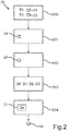
- Fig. 2 illustrates a method 20 for this, which can be carried out by the control device 12 for determining the shape and / or dimension 19 of the object 15.
- the background 15 ′ can be a driving surface.
- Fig. 3 shows an exemplary image 21 as it may have been generated with the camera 11.
- the control device 12 can define or set at least one scan line 23 in a first of the images, here the image 21 as an example.
- Each scan line 23 can correspond to the image of a ray 23 '(see Fig. 1 ), which extends straight away from the motor vehicle at a height He.
- the height He can be a known height of the object 15.
- the same scan lines 23 can be defined in the image 22 and in every other image. They thus represent scan lines corresponding to the scan lines 23 of the image 21.
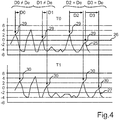
- a profile 25 resulting along the scan line is formed for a predetermined image property 24, as is exemplified in FIG Fig. 4 is illustrated.
- Fig. 4 illustrates along an axis 26, which corresponds to the course of a scan line 23 of the image 21, the resulting profile 25 for an image property 24 which represents the value of an edge detection.
- the difference between the brightness values of neighboring pixels along the scan line 23 can be calculated for each point of the profile 25.
- Fig. 4 further illustrates how a corresponding profile 27 can be determined on the basis of the image property 24 for the image 22, that is to say for the measurement time T1, for the corresponding scan line in the image 22.
- At least one characteristic area 29 can now be determined for the profile 25 on the basis of a feature detection 28.
- the feature detection 28 can, for example, identify local maxima as a respective characteristic area.
- Each characteristic area 29 of the profile 25 can now be recognized again in the profile 27 as a recognized characteristic area 30. For example, this can be done on the basis of a correlation.
- a displacement width D0, D1, D2, D3 of the respective characteristic area 29 along the respective scan line 23 resulting between the measurement times T0 and T1 can now be determined for each characteristic area 29.
- the displacement distance D0, D1, D2, D3 depends on the one hand on the movement distance of the motor vehicle 10 during the approach 17 between the two measurement times T0, T1 and on the other hand on the distance between the image content displayed in the characteristic area 29 and the camera 11 The effect of parallax results from different distances between the image content, that is, depending on the distance between the respective image content and the camera 11, there is a different displacement distance D0, D1, D2, D3.
- a segmentation criterion 31 can be used as a basis for this, which provides, for example, a comparison of the respective displacement widths D0, D1, D2, D3 with an expected displacement width De, which results from the known height He of the object 15.
- the comparison can provide a tolerance interval within which an identity of the respective displacement width D0, D1, D2, D3 to the expected displacement width De is recognized or signaled.
- Fig. 3 illustrates how a segmentation 32 into two segments 33, 34 can be carried out along a scan line 23.
- the segment 33 can describe a section of a scan line 23 which is assigned to the object 15.
- the segment 34 can describe a section of a scan line 23 which is assigned to the background 15 '.
- a description of the dimensions and / or shape 19 of the object 15 can now be determined from all segments 33 of all scan lines 23.
- the dimension and / or shape 19 can be signaled to a further component in the motor vehicle, for example a driver assistance system, which brings the motor vehicle 10 autonomously or automatically to the object 15.
- a driver assistance system which brings the motor vehicle 10 autonomously or automatically to the object 15.
- the control device 12 carries out an analysis of the movement in the individual images 21, 22, taking into account the vehicle movement during the approach 17.
- Individual image areas of the images 21, 22 are assigned to the background 15 '(for example the driving surface or the ground level) on the one hand and to the object 15 of known height He on the other hand.
- the image areas are represented in the form of scan lines 23. In the three-dimensional space 23 ′, these correspond to the known height He of the object 15 and the shape of which is projected or imaged as scan lines 23 in the respective image 21, 22.
- These scan lines 23 are analyzed over temporally adjacent images 21, 22 with regard to their image property 24, for example by means of an edge detection function.
- each scan line 23 It is checked which parts or segments 33, 34 of each scan line 23 correspond to the expected object movement according to the expected displacement De (results in assignment to object 15) and which contradict the assumption (corresponds to assignment to background 15 '). With a sufficient number of scan lines 23 (for example more than 5, in particular more than 10), this enables segmentation 32 which can be used to determine the external shape of the object 15. A precise and unobstructed approach or approach 17 to the object 15 is thus possible.
- the height of this closest point can be deduced. This can be used as a further security feature.
- the motor vehicle 10 can thus be approached precisely to the target position described. If necessary, an offset can be used depending on the target position in order to position yourself relative to it.
- the approach presented offers a recognition of the outer shape of the object 15 and a recognition of an object geometry by analyzing an image property, for example an edge function, whereby a collision of the motor vehicle 10 with the object 15 can be prevented and an approach to a target position can be carried out.
- an image property for example an edge function
- the object 15 can be a trailer drawbar of a trailer 16, to whose trailer claw the motor vehicle 10 is to be coupled or docked.
- the trailer coupling 18 (trailer coupling device) can be positioned under the trailer claw, which defines the target position.
- the real target position can provide an offset, namely half the diameter of the coupling dome of the trailer claw to the described closest point of the object 15 to the motor vehicle 10.
Description
Die Erfindung betrifft ein Verfahren zum Vermessen eines Objekts in einem Außenbereich eines Kraftfahrzeugs. Das Vermessen erfolgt optisch mittels einer Kamera, während das Kraftfahrzeug relativ zu dem Objekt bewegt wird. Zu der Erfindung gehören auch eine Steuervorrichtung zum Durchführen des Verfahrens sowie ein Kraftfahrzeug mit der erfindungsgemäßen Steuervorrichtung.The invention relates to a method for measuring an object in an exterior area of a motor vehicle. The measurement is carried out optically by means of a camera while the motor vehicle is being moved relative to the object. The invention also includes a control device for performing the method and a motor vehicle with the control device according to the invention.
Möchte man ein Kraftfahrzeug relativ zu einem Objekt manövrieren und/oder das Objekt mit dem Kraftfahrzeug verbinden oder an das Kraftfahrzeug ankuppeln, so ist es vorteilhaft, die Abmessungen oder die Geometrie des Objekts zu kennen. Dies ist insbesondere dann der Fall, wenn das Manövrieren des Kraftfahrzeugs automatisiert erfolgen soll, das heißt ohne ein Zutun eines Fahrers durch eine Steuervorrichtung vorgenommen wird.If you want to maneuver a motor vehicle relative to an object and / or connect the object to the motor vehicle or couple it to the motor vehicle, it is advantageous to know the dimensions or the geometry of the object. This is the case in particular when the maneuvering of the motor vehicle is to be carried out automatically, that is to say is carried out by a control device without the driver having to do anything.
Ein Beispiel für ein solches Manövrieren ist das Ankuppeln eines Anhängers an ein Kraftfahrzeug. Um die Anhängerkupplung des Kraftfahrzeugs an die Deichsel des Anhängers anzunähern und in einer vorbestimmten Zielposition oder Ankuppelposition zu positionieren, muss die räumliche Lage der Anhängerkupplung bekannt sein.An example of such maneuvering is hitching a trailer to a motor vehicle. In order to bring the trailer coupling of the motor vehicle closer to the drawbar of the trailer and to position it in a predetermined target position or coupling position, the spatial position of the trailer coupling must be known.
Aus der
Aus der
Aus der
Aus der
Aus der
Aus der
Die
Der Erfindung liegt die Aufgabe zugrunde, von einem Kraftfahrzeug aus eine Form eines Objekts zu erkennen, dass sich in einem Außenbereich eines Kraftfahrzeugs befindet.The invention is based on the object of recognizing, from a motor vehicle, a shape of an object that is located in an outside area of a motor vehicle.
Die Aufgabe wird durch die Gegenstände der unabhängigen Patentansprüche gelöst. Vorteilhafte Ausführungsformen der Erfindung sind durch die abhängigen Patentansprüche, die folgende Beschreibung sowie die Figuren gegeben.The object is achieved by the subjects of the independent claims. Advantageous embodiments of the invention are given by the dependent claims, the following description and the figures.
Durch die Erfindung ist ein Verfahren zur Formerkennung eines Objekts in einem Außenbereich eines Kraftfahrzeugs bereitgestellt. Das Verfahren wird durchgeführt, während sich das Kraftfahrzeug relativ zu dem Objekt bewegt. Durch eine Steuervorrichtung des Kraftfahrzeugs wird hierbei mittels einer Kamera zu zumindest zwei unterschiedlichen Messzeitpunkten jeweils ein Bild erzeugt. Das Bild zeigt das Objekt vor einem Hintergrund des Außenbereichs. In einem ersten der Bilder wird zumindest eine Abtastlinie oder Scanlinie festgelegt. Eine Scanlinie ist eine gedachte Linie in dem Bild, entlang welcher Pixelwerte einzelner Pixel des Bildes betrachtet oder analysiert werden. Zu jeder Scanlinie wird in jedem anderen der Bilder eine korrespondierende Scanlinie festgelegt. Jede korrespondierende Scanlinie weist den gleichen Verlauf in dem jeweiligen Bild auf wie die zugehörige Scanlinie des ersten Bildes, mit welcher sie korrespondiert. Eine korrespondierende Scanlinie weist also die gleiche Form wie die zugehörige Scanlinie auf.The invention provides a method for recognizing the shape of an object in an exterior area of a motor vehicle. The method is carried out while the motor vehicle is moving relative to the object. By means of a control device of the motor vehicle, an image is generated in each case by means of a camera at at least two different measurement times. The picture shows the object against a background of the outside area. At least one scan line or scan line is defined in a first of the images. A scan line is an imaginary line in the image along which pixel values of individual pixels of the image are viewed or analyzed. A corresponding scan line is defined for each scan line in each of the other images. Each corresponding scan line has the same course in the respective image as the associated scan line of the first image with which it corresponds. A corresponding scan line therefore has the same shape as the associated scan line.
Zu jeder Scanlinie des ersten Bilds wird zu einer vorbestimmten Bildeigenschaft, beispielsweise der Pixelhelligkeit oder Farbewerte der Pixel, ein sich entlang der Scanlinie ergebendes Profil ermittelt. Entlang der jeweils korrespondierenden Scanlinie jedes anderen Bilds wird entsprechend ein sich ergebendes korrespondierendes Profil ermittelt. Jedes Profil beschreibt also den jeweiligen Verlauf der Bildeigenschaft, also beispielsweise der Pixelhelligkeit oder der Farbewerte der Pixel, entlang der jeweiligen Scanlinie. Für jede Scanlinie des ersten Bilds wird anhand des Profils der Scanlinie zumindest ein charakteristischer Bereich der Scanlinie ermittelt. Ein solcher charakteristischer Bereich ist ein Profilabschnitt mit einer vorbestimmten charakteristischen Form. Ein Beispiel für so einen charakteristischen Bereich kann ein Maximum oder eine Doppelspitze im Verlauf des Profils sein. Ein solcher charakteristischer Bereich kann in einer korrespondierenden Scanlinie wiedererkannt werden. Entsprechend wird durch Vergleichen des Profils jeder Scanlinie des ersten Bilds mit dem jeweils korrespondierenden Profil jedes anderen Bilds der zumindest eine charakteristische Bereich in dem jeweils korrespondierenden Profil wiedererkannt. Mit anderen Worten wird also für jede Scanlinie des ersten Bilds zumindest ein charakteristischer Bereich des Profils dieser Scanlinie ermittelt und durch Vergleichen des Profils mit dem jeweiligen korrespondierenden Profil jedes anderen Bilds der zumindest eine charakteristische Bereich in dem jeweils korrespondierenden Profil wiedererkannt. Man kann nun erkennen, wo in dem Profil und dem korrespondierenden Profil sich der charakteristische Bereich jeweils befindet. Man kann erkennen, wie weit sie gegeneinander verschoben sind. Für jeden charakteristischen Bereich des Profils jeder Scanlinie wird dann eine sich zwischen den Messzeitpunkten ergebende Verschiebeweite des charakteristischen Bereichs entlang der jeweiligen Scanlinie ermittelt. Man überprüft oder erkennt also, wie weit der charakteristische Bereich sich aufgrund der relativen Bewegung des Kraftfahrzeugs zum Objekt in dem Bild entlang der jeweiligen Scanlinie verschoben hat. Diese Verschiebung ist abhängig von dem Abstand des jeweiligen Bildinhalts (Objekt oder Hintergrund) zu der Kamera. Dieser Effekt wird auch als Parallaxe bezeichnet. Entsprechend wird entlang jeder Scanlinie in Abhängigkeit von der ermittelten Verschiebeweite jedes charakteristischen Bereichs des Profils der Scanlinie zwischen Objekt und Hintergrund unterschieden. Eine solche Unterscheidung wird auch als Segmentierung bezeichnet. Die Segmentierung wird hier rein optisch auf der Grundlage von zumindest zwei Bildern der Kamera durchgeführt.For each scan line of the first image, a profile resulting along the scan line is determined for a predetermined image property, for example the pixel brightness or color values of the pixels. A resulting corresponding profile is determined along the respective corresponding scan line of every other image. Each profile thus describes the respective course of the image property, for example the pixel brightness or the color values of the pixels, along the respective scan line. For each scan line of the first image, at least one characteristic area of the scan line is determined on the basis of the profile of the scan line. Such a characteristic area is a profile section with a predetermined characteristic shape. An example of such a characteristic area can be a maximum or a double peak in the course of the profile. Such a characteristic area can be recognized in a corresponding scan line. Correspondingly, by comparing the profile of each scan line of the first image with the respectively corresponding profile of every other image, the at least one characteristic area in the respectively corresponding profile is recognized. In other words, at least one characteristic area of the profile of this scan line is determined for each scan line of the first image and the at least one characteristic area is recognized in the respective corresponding profile by comparing the profile with the respective corresponding profile of every other image. You can now see where the characteristic area is located in the profile and the corresponding profile. You can see how far they are shifted from one another. For each characteristic area of the profile of each scan line, a displacement width of the characteristic area along the respective scan line resulting between the measurement times is then determined. One checks or recognizes how far the characteristic area extends due to the relative movement of the motor vehicle to the Has moved the object in the image along the respective scan line. This shift depends on the distance between the respective image content (object or background) and the camera. This effect is also known as parallax. Correspondingly, a distinction is made between the object and the background along each scan line as a function of the determined displacement width of each characteristic area of the profile of the scan line. Such a distinction is also referred to as segmentation. The segmentation is carried out here purely optically on the basis of at least two images from the camera.
Die Scanlinien und die korrespondierenden Scanlinien weisen einen Verlauf auf, welcher einem Abbild eines Strahls entspricht, der sich virtuell in dem Außenbereich dreidimensional in einer vorbestimmten Höhe gerade von dem Kraftfahrzeug weg erstreckt. Hierdurch ergibt sich der Vorteil, dass eine Komponente des Objekts, die in dem ersten Bild auf einer ersten bestimmten Scanlinie liegt, bei einer Bewegung des Kraftfahrzeugs auf einer korrespondierenden Scanlinie eines anderen Bildes zu liegen kommt. Die vorbestimmte Höhe ist eine erwartete oder bekannte Höhe des Objekts. Hierdurch ist die Wahrscheinlichkeit verringert, dass die Komponente zwischen zwei Bildern auf unterschiedlichen Scanlinien zu liegen kommt.The scan lines and the corresponding scan lines have a course which corresponds to an image of a beam which virtually extends three-dimensionally in the outer area at a predetermined height straight away from the motor vehicle. This has the advantage that a component of the object that lies on a first specific scan line in the first image comes to rest on a corresponding scan line of another image when the motor vehicle is moving. The predetermined height is an expected or known height of the object. This reduces the likelihood that the component will come to lie on different scan lines between two images.
Durch die Erfindung ergibt sich der Vorteil, dass auf der Grundlage von Kamerabildern einer Kamera ohne Vorkenntnis über das Objekt dessen Form erkannt werden kann. Somit lässt sich das Verfahren mit geringem zusätzlichen Bauteilaufwand und Verschaltungsaufwand in einem Kraftfahrzeug realisieren.The invention has the advantage that, on the basis of camera images from a camera, the shape of the object can be recognized without any prior knowledge of the object. The method can thus be implemented in a motor vehicle with little additional component outlay and interconnection outlay.
Die Erfindung umfasst auch Ausführungsformen, durch die sich zusätzliche Vorteile ergeben.The invention also encompasses embodiments which result in additional advantages.
Eine Ausführungsform sieht vor, dass zum Unterscheiden zwischen Objekt und Hintergrund jedem charakteristischen Bereich des Profils jeder Scanlinie in Abhängigkeit von seiner Verschiebeweite ein Höhenwert zugeordnet wird und hierdurch entlang jeder Scanlinie ein Höhenprofil erzeugt wird. Anhand des jeweiligen Höhenprofils wird dann entlang jeder Scanlinie zwischen Objekt und Hintergrund unterschieden. Hierdurch ergibt sich der Vorteil, dass auch ein Oberflächenprofil des Objekts ermittelt wird (Höhenprofil im Bereich des Objekts).One embodiment provides that, in order to differentiate between the object and the background, a height value is assigned to each characteristic area of the profile of each scan line as a function of its displacement width, and a height profile is thereby generated along each scan line. Based on the respective height profile, a distinction is then made between the object and the background along each scan line. This has the advantage that a surface profile of the object is also determined (height profile in the area of the object).
Eine Ausführungsform sieht vor, dass die vorbestimmte Bildeigenschaft, auf deren Grundlage des jeweiligen Profil entlang jeder Scanlinie gebildet wird, einen Farbwert und/oder einen Kontrastwert und/oder einen Kantendetektionswert eines Bildinhalts des Bildes umfasst. Ein Kantendetektionswert kann beispielsweise auf der Grundlage einer örtlichen Ableitung gebildet werden, wie er beispielsweise als Differenz der Helligkeitswerte benachbarter Pixel des Bildes gebildet werden kann. Es werden hierbei natürlich zum Ermitteln des Profils diejenigen Pixel verwendet, die entlang der Scanlinie angeordnet sind. Die besagten Bildeigenschaften weisen den Vorteil auf, dass mit ihnen optisch zwischen Objekt und Hintergrund unterschieden werden kann.One embodiment provides that the predetermined image property, on the basis of which the respective profile is formed along each scan line, comprises a color value and / or a contrast value and / or an edge detection value of an image content of the image. For example, an edge detection value can be based on a local derivative can be formed, as it can be formed, for example, as the difference between the brightness values of neighboring pixels of the image. Of course, those pixels that are arranged along the scan line are used to determine the profile. The aforementioned image properties have the advantage that they can be used to distinguish optically between the object and the background.
Eine Ausführungsform sieht vor, dass die charakteristischen Bereiche mittels einer vorbestimmten Merkmalsdetektion festgelegt werden, welche zumindest ein vorbestimmtes, charakteristisches Muster in dem jeweiligen Profil als charakteristischen Bereich identifiziert. Ein solches charakteristisches Muster kann beispielsweise ein lokales Maximum oder ein lokales Minimum sein. Es kann auch vorgesehen sein, ein solches lokales Maximum oder lokales Minimum mit einer vorbestimmten Mindestausprägung, also beispielsweise einer vorbestimmten Mindesthöhe oder Mindesttiefe zu fordern, damit ein charakteristischer Bereich identifiziert wird. Die Ausführungsform weist den Vorteil auf, dass in einem Profil automatisiert zumindest ein charakteristischer Bereich identifiziert werden kann.One embodiment provides that the characteristic areas are determined by means of a predetermined feature detection which identifies at least one predetermined, characteristic pattern in the respective profile as a characteristic area. Such a characteristic pattern can be, for example, a local maximum or a local minimum. Provision can also be made to require such a local maximum or local minimum with a predetermined minimum expression, that is to say for example a predetermined minimum height or minimum depth, so that a characteristic area is identified. The embodiment has the advantage that at least one characteristic area can be identified automatically in a profile.
Eine Ausführungsform sieht vor, dass eine Geradeausfahrt des Kraftfahrzeugs erkannt wird und die Bilder während der Geradeausfahrt erzeugt werden. Hierdurch wird also das Erfassen der Bilder zu einem Zeitpunkt ausgelöst, der günstig ist, um sicherzustellen, dass sich in dem Profil charakteristische Bereiche ergeben, die auch in jedem korrespondierenden Profil enthalten sind.One embodiment provides that straight-ahead travel of the motor vehicle is recognized and the images are generated during straight-ahead travel. This therefore triggers the acquisition of the images at a point in time that is favorable to ensure that characteristic areas arise in the profile which are also contained in each corresponding profile.
Falls das Kraftfahrzeug keine Geradeausfahrt durchführt, sieht eine Ausführungsform vor, dass die Form der Scanlinien in Abhängigkeit von einem Lenkwinkel des Kraftfahrzeugs eingestellt wird. Hierdurch kann auch bei einer Kurvenfahrt des Kraftfahrzeugs ermöglicht werden, dass eine Komponente des Objekts, die auf einer bestimmten Scanlinie des ersten Objekts zu liegen kommt, sich bei der Weiterfahrt auf der Scanlinie entlang bewegt und somit auch auf einer korrespondierenden Scanlinie eines anderen Bilds zu liegen kommt. Entsprechend findet sich dann auch in dem Profil der Scanlinie ein charakteristischer Bereich, der im korrespondierenden Profil der korrespondierenden Scanlinie enthalten ist und somit wiedererkannt werden kann.If the motor vehicle is not driving straight ahead, one embodiment provides that the shape of the scan lines is set as a function of a steering angle of the motor vehicle. This enables a component of the object that comes to rest on a certain scan line of the first object to move along the scan line when the motor vehicle is cornering and thus also to lie on a corresponding scan line of another image comes. Correspondingly, there is then also a characteristic area in the profile of the scan line, which is contained in the corresponding profile of the corresponding scan line and can thus be recognized.
Eine Ausführungsform sieht vor, dass die Höhenwerte der charakteristischen Bereiche auf eine vorbestimmte Anzahl von möglichen Höhenwerten gerastert werden. Hierdurch kann ein Rauschen vermindert werden. Insbesondere kann vorgesehen sein, dass zwei mögliche Höhenwerte vorgesehen werden, von denen einer eine erwartete Höhe des Objekts und ein zweiter eine erwartete Höhe des Hintergrunds darstellt und somit die näheren Höhenprofile (zweiwertige Höhenprofile) erzeugt werden. Durch Rastern auf erwartete Höhenwerte des Objekts und des Hintergrunds wird in vorteilhafter Weise eine Mehrdeutigkeit aufgrund von Unebenheiten oder aufgrund von Zwischenwerten, wie sie sich beispielsweise durch weitere Objekte ergeben, die eine geringere Höhe als das Objekt aufweisen, aufgehoben. Wird beispielsweise als Objekt eine Anhängerkupplung erfasst, die auf einem gradbewachsenen Boden steht, so werden sämtliche Grashalme dem Boden zugeordnet und im Höhenprofil ein flacher Boden dargestellt.One embodiment provides that the height values of the characteristic areas are rasterized to a predetermined number of possible height values. This can reduce noise. In particular, it can be provided that two possible Height values are provided, one of which represents an expected height of the object and a second an expected height of the background, and thus the closer height profiles (two-valued height profiles) are generated. By rasterizing for expected height values of the object and the background, an ambiguity due to unevenness or due to intermediate values, such as arise, for example, from other objects that have a lower height than the object, is advantageously eliminated. If, for example, a trailer coupling is detected as an object that is standing on a straight overgrown ground, then all blades of grass are assigned to the ground and a flat ground is shown in the height profile.
Eine Ausführungsform sieht vor, dass als der Hintergrund ein Fahruntergrund des Kraftfahrzeugs erfasst wird. Mit anderen Worten wird die Kamera derart ausgerichtet, dass ihr Erfassungsbereich von oben auf das Objekt gerichtet ist. Als Hintergrund ergibt sich dann der Fahruntergrund des Kraftfahrzeugs. Hierdurch ergibt sich der Vorteil, dass der beschriebene Effekt der Parallaxe eine wirkungsvolle Unterscheidung zwischen Objekt und Hintergrund ermöglicht.One embodiment provides that a driving surface of the motor vehicle is recorded as the background. In other words, the camera is aligned in such a way that its detection range is directed onto the object from above. The driving surface of the motor vehicle then results as the background. This has the advantage that the described effect of parallax enables an effective differentiation between the object and the background.
Eine Ausführungsform sieht vor, dass in den Höhenprofilen all diejenigen Abschnitte, deren Höhenwert in einem vorbestimmten Werteintervall liegt, dem Objekt zugeordnet werden. Hierdurch ergibt sich eine Segmentierung, die zusätzlich eine Oberflächenbeschreibung oder Beschreibung der Form des Objekts ergibt.One embodiment provides that in the height profiles all those sections whose height value lies within a predetermined value interval are assigned to the object. This results in a segmentation that also results in a surface description or description of the shape of the object.
Durch die Segmentierung kann das Objekt vermessen werden oder zumindest eine Form oder Breite des Objekts erfasst oder beschrieben werden.As a result of the segmentation, the object can be measured or at least a shape or width of the object can be recorded or described.
Eine Ausführungsform sieht vor, dass die Höhenprofile der Scanlinie zu einer zweidimensionalen Höhenkarte zusammengefasst werden. Mit anderen Worten wir die Linienstruktur beseitigt, indem zwischen den Scanlinien Höhenwerte interpoliert werden. Hierdurch ergibt sich eine flächige Höhenkarte. Diese Ausführungsform weist den Vorteil auf, dass für jeden Punkt der zweidimensionalen Fläche ein Höhenwert definiert ist.One embodiment provides that the height profiles of the scan line are combined to form a two-dimensional height map. In other words, the line structure is eliminated by interpolating height values between the scan lines. This results in a flat height map. This embodiment has the advantage that a height value is defined for each point on the two-dimensional surface.
Eine Ausführungsform sieht vor, dass die besagten Bilder während einer Annäherung des Kraftfahrzeugs an eine Anhängerdeichsel eines Anhängers ermittelt werden. Das Objekt ist also die Anhängerdeichsel. Anhand der beschriebenen Unterscheidung zwischen Objekt und Hintergrund wird eine Abmessung und/oder Form der Anhängerdeichsel ermittelt. Die Annäherung des Kraftfahrzeugs bedeutet, dass das Objekt, also die Anhängerdeichsel, noch nicht an das Kraftfahrzeug angekuppelt ist. Das Kraftfahrzeug fährt auf das Objekt, also insbesondere die Anhängerdeichsel, zu. Wird dann die Anhängerdeichsel erreicht, so ist deren Abmessung und/oder Form ermittelt. Damit kann ein Ankuppelvorgang oder das Positionieren einer Anhängerkupplung relativ zur Anhängerdeichsel auf der Grundlage der ermittelten Abmessung und/oder Form durchgeführt werden. Es ist also nicht nötig, zuvor beispielsweise auf der Grundlage einer Datendatei mit Geometriedaten die Form und/oder Abmessung der Anhängerdeichsel bekannt zu machen. Sie wird automatisch bei Annäherung des Kraftfahrzeugs an die Anhängerdeichsel ermittelt.One embodiment provides that said images are determined while the motor vehicle is approaching a trailer drawbar of a trailer. So the object is the trailer drawbar. On the basis of the described differentiation between object and background, a dimension and / or shape of the trailer drawbar is determined. The approach of the motor vehicle means that the object, that is to say the trailer drawbar, is not yet coupled to the motor vehicle. The motor vehicle drives onto the object, that is especially the trailer drawbar, too. If the trailer drawbar is then reached, its dimensions and / or shape is determined. A coupling process or the positioning of a trailer coupling relative to the trailer drawbar can thus be carried out on the basis of the determined dimensions and / or shape. It is therefore not necessary to make known the shape and / or dimensions of the trailer drawbar beforehand, for example on the basis of a data file with geometric data. It is determined automatically when the vehicle approaches the trailer drawbar.
Um das erfindungsgemäßen Verfahren in einem Kraftfahrzeug durchzuführen, ist durch die Erfindung auch eine Steuervorrichtung für ein Kraftfahrzeug bereitgestellt. Die Steuervorrichtung kann als ein Steuergerät des Kraftfahrzeugs ausgestaltet sein. Die Steuervorrichtung weist eine Recheneinrichtung auf, die dazu eingerichtet ist, eine Ausführungsform des erfindungsgemäßen Verfahrens durchzuführen. Hierzu kann die Recheneinrichtung einen Programmcode umfassen, der bei Ausführen durch die Recheneinrichtung die Ausführungsform des Verfahrens durchführt. Der Programmcode kann in einem Datenspeicher der Recheneinrichtung gespeichert sein.In order to carry out the method according to the invention in a motor vehicle, the invention also provides a control device for a motor vehicle. The control device can be designed as a control unit of the motor vehicle. The control device has a computing device which is set up to carry out an embodiment of the method according to the invention. For this purpose, the computing device can comprise a program code which, when executed by the computing device, carries out the embodiment of the method. The program code can be stored in a data memory of the computing device.
Die Erfindung umfasst auch ein Kraftfahrzeug mit zumindest einer Kamera für einen Außenbereich des Kraftfahrzeugs und mit einer Ausführungsform der erfindungsgemäßen Steuervorrichtung. Die Steuervorrichtung ist mit der zumindest einen Kamera gekoppelt. Somit kann die Steuervorrichtung auf der Grundlage von Bildern der zumindest einen Kamera das erfindungsgemäße Verfahren durchführen. Das erfindungsgemäße Kraftfahrzeug ist bevorzugt als Kraftwagen, insbesondere Personenkraftwagen oder Lastkraftwagen, ausgestaltet.The invention also includes a motor vehicle with at least one camera for an outside area of the motor vehicle and with an embodiment of the control device according to the invention. The control device is coupled to the at least one camera. The control device can thus carry out the method according to the invention on the basis of images from the at least one camera. The motor vehicle according to the invention is preferably designed as a motor vehicle, in particular a passenger vehicle or truck.
Zu der Erfindung gehören auch die Kombinationen der beschriebenen Ausführungsformen.The invention also includes the combinations of the embodiments described.
Im Folgenden ist ein Ausführungsbeispiel der Erfindung beschrieben. Hierzu zeigt:
- Fig. 1
- eine schematische Darstellung einer Ausführungsform des erfindungsgemäßen Kraftfahrzeugs;
- Fig. 2
- ein Flussschaudiagramm einer Ausführungsform des erfindungsgemäßen Verfahrens;
- Fig. 3
- eine schematische Darstellung eines Bilds einer Kamera mit einem darin abgebildeten Objekt; und
- Fig. 4
- ein Diagramm mit einem Profil und einem korrespondierenden Profil, die zu unterschiedlichen Messzeitpunkten erfasst wurden.
- Fig. 1
- a schematic representation of an embodiment of the motor vehicle according to the invention;
- Fig. 2
- a flow chart of an embodiment of the method according to the invention;
- Fig. 3
- a schematic representation of an image of a camera with an object imaged therein; and
- Fig. 4
- a diagram with a profile and a corresponding profile that were recorded at different measurement times.
Bei dem im Folgenden erläuterten Ausführungsbeispiel handelt es sich um eine bevorzugte Ausführungsform der Erfindung. Bei dem Ausführungsbeispiel stellen die beschriebenen Komponenten der Ausführungsform jeweils einzelne, unabhängig voneinander zu betrachtende Merkmale der Erfindung dar, welche die Erfindung jeweils auch unabhängig voneinander weiterbilden und damit auch einzeln oder in einer anderen als der gezeigten Kombination als Bestandteil der Erfindung anzusehen sind. Des Weiteren ist die beschriebene Ausführungsform auch durch weitere der bereits beschriebenen Merkmale der Erfindung ergänzbar.The exemplary embodiment explained below is a preferred embodiment of the invention. In the exemplary embodiment, the described components of the embodiment each represent individual features of the invention that are to be considered independently of one another, which also develop the invention independently of one another and are therefore also to be regarded as part of the invention individually or in a combination other than the one shown. Furthermore, the described embodiment can also be supplemented by further features of the invention that have already been described.
In den Figuren sind funktionsgleiche Elemente jeweils mit denselben Bezugszeichen versehen.In the figures, functionally identical elements are each provided with the same reference symbols.
Hierzu kann eine Form oder Abmessung 19 des Objekts 15 durch die Steuervorrichtung 12 ermittelt und signalisiert werden.For this purpose, a shape or
In einem Schritt S10 kann während der Annäherung 17 durch die Steuervorrichtung 12 mittels der Kamera 11 zu zwei unterschiedlichen Messzeitpunkten T0, T1 jeweils ein Kamerabild oder kurz Bild 21, 22, des Objekts 15 vor einem Hintergrund 15' erzeugt oder aufgenommen werden. Der Hintergrund 15' kann bei der dargestellten Ausrichtung des Erfassungsbereichs 13 der Kamera 11 ein Fahruntergrund sein.In a step S10, during the approach 17 by the
Für die weitere Erläuterung des Verfahrens 20 wird auf
In einem Schritt S11 kann die Steuervorrichtung 12 in einem ersten der Bilder, hier beispielhaft das Bild 21, zumindest eine Scanlinie 23 definiert oder festgelegt werden. Jede Scanlinie 23 kann dem Abbild eines Strahls 23' entsprechen (siehe
Zu jeder Scanlinie 23 des Bilds 21 wird zu einer vorbestimmten Bildeigenschaft 24 ein sich entlang der Scanlinie ergebendes Profil 25 gebildet, wie es beispielhaft in
In einem Schritt S12 kann nun für das Profil 25 auf der Grundlage einer Merkmalsdetektion 28 zumindest ein charakteristischer Bereich 29 ermittelte werden. Die Merkmalsdetektion 28 kann beispielsweise lokale Maxima als jeweiligen charakteristischen Bereich identifizieren.In a step S12, at least one
Jeder charakteristische Bereich 29 des Profils 25 kann nun in dem Profil 27 als wiedererkannter charakteristischer Bereich 30 wieder erkannt werden. Beispielsweise kann dies auf der Grundlage einer Korrelation erfolgen.Each
In einem Schritt S13 kann nun für jeden charakteristischen Bereich 29 eine sich zwischen den Messzeitpunkten T0 und T1 ergebende Verschiebeweite D0, D1, D2, D3 des jeweiligen charakteristischen Bereichs 29 entlang der jeweiligen Scanlinie 23 ermittelt werden. Die Verschiebeweite D0, D1, D2, D3 hängt zum einen ab von der Bewegungsweite des Kraftfahrzeugs 10 während der Annäherung 17 zwischen den beiden Messzeitpunkten T0, T1 und zum anderen von dem Abstand des jeweils im charakteristischen Bereich 29 dargestellten Bildinhalts zur Kamera 11. Durch die unterschiedlichen Abstände der Bildinhalte ergibt sich der Effekt der Parallaxe, das heißt je nach Abstand des jeweiligen Bildinhalts zur Kamera 11 ergibt sich eine andere Verschiebeweite D0, D1, D2, D3.In a step S13, a displacement width D0, D1, D2, D3 of the respective
In einem Schritt S14 kann nun entlang jeder Scanlinie 23 in Abhängigkeit von der ermittelten Verschiebeweite D0, D1, D2, D3 jedes charakteristischen Bereichs 29 des Profils 25 der jeweiligen Scanlinie 23 zwischen dem Objekt 15 und dem Hintergrund 15' unterschieden werden.In a step S14, a distinction can now be made between the
Hierzu kann ein Segmentierungskriterium 31 zugrunde gelegt werden, welches beispielsweise einen Vergleich der jeweiligen Verschiebeweite D0, D1, D2, D3 mit einer erwarteten Verschiebeweite De vorsieht, die aus der bekannten Höhe He des Objekts 15 resultiert. Der Vergleich kann hierbei ein Toleranzintervall vorsehen, innerhalb welchem eine Identität der jeweiligen Verschiebeweite D0, D1, D2, D3 zur erwarteten Verschiebeweite De erkannt oder signalisiert wird.A
Aus allen Segmenten 33 aller Scanlinien 23 kann nun eine Beschreibung der Abmessung und/oder Form 19 des Objekts 15 ermittelt werden.A description of the dimensions and / or
Die Abmessung und/oder Form 19 kann in dem Kraftfahrzeug einer weiteren Komponente signalisiert werden, beispielsweise einem Fahrerassistenzsystem, welches das Kraftfahrzeug 10 autonom oder automatisiert an das Objekt 15 heranführt.The dimension and / or
Somit ist eine präzise Anfahrt oder Annäherung 17 des Kraftfahrzeugs 10 zu einem Objekt 15 mit bekannter Höhe He möglich, auch wenn keine Kenntnis der Form 19 vorliegt. Eine Kenntnis der Form ist nicht erforderlich. Die Form 19 des Objekts 15 wird detektiert. Hierdurch kann eine präzise Zielposition beispielsweise der Anhängerkupplung 18 erreicht werden und/oder eine Kollision mit dem Objekt 15 bei der Annäherung 17 vermieden werden.Thus, a precise approach or approach 17 of the
Die Steuervorrichtung 12 führt hierzu eine Analyse der Bewegung in den einzelnen Bildern 21, 22 unter Berücksichtigung der Fahrzeugbewegung bei der Annäherung 17 durch. Einzelne Bildbereiche der Bilder 21, 22 werden den Hintergrund 15' (bspw dem Fahruntergrund oder der Bodenebene) einerseits und dem Objekt 15 bekannter Höhe He andererseits zugeordnet. Die Bildbereiche werden in Form von Scanlinien 23 repräsentiert. Diese entsprechen im dreidimensionalen Raum 23' die in der bekannten Höhe He des Objekts 15 verlaufen und deren Form als Scanlinien 23 in das jeweilige Bild 21, 22 projiziert oder abgebildet ist. Diese Scanlinien 23 werden über zeitlich benachbarte Bilder 21, 22 in Bezug auf ihre Bildeigenschaft 24, beispielsweise mittels einer Kantendetektionsfunktion analysiert. Es wird geprüft, welche Teile oder Segmente 33, 34 jeder Scanlinie 23 der erwarteten Objektbewegung gemäß der erwarteten Verschiebeweite De entsprechen (ergibt Zuordnung zum Objekt 15) und welche der Annahme wiedersprechen (entspricht Zuordnung zum Hintergrund 15'). Dies ermöglicht bei ausreichender Anzahl von Scanlinien 23 (bspw mehr als 5, insbesondere mehr als 10), eine Segmentierung 32, die für eine Bestimmung der Außenform des Objekts 15 benutzt werden kann. Damit ist eine präzise und hindernisfreie Anfahrt oder Annäherung 17 an das Objekt 15 möglich.To this end, the
Weiterhin kann durch Triangulation des nächstliegenden Punkts des Objekts zum Kraftfahrzeug 10 auf die Höhe dieses nächstliegenden Punktes geschlossen werden. Dies kann als weiteres Sicherheitsmerkmal verwendet werden. Das Kraftfahrzeug 10 kann damit präzise zu der beschriebenen Zielposition angenähert werden. Bei Bedarf kann in Abhängigkeit von der Zielposition ein Offset genutzt werden, um sich relativ dazu zu positionieren.Furthermore, by triangulating the closest point of the object to the
Der vorgestellte Ansatz bietet eine Erkennung der äußeren Form des Objekts 15 und einer Erkennung einer Objektgeometrie durch Analyse einer Bildeigenschaft, beispielsweise einer Kantenfunktion, wodurch eine Kollision des Kraftfahrzeugs 10 mit dem Objekt 15 verhindert werden kann und eine Anfahrt zu einer Zielposition durchgeführt werden kann.The approach presented offers a recognition of the outer shape of the
Das Objekt 15 kann hierbei eine Anhängerdeichsel eines Anhängers 16 sein, an deren Anhängerklaue das Kraftfahrzeug 10 angekuppelt oder angedockt werden soll. Dabei kann die Anhängerkupplung 18 (Anhängerankuppelvorrichtung) unter der Anhängerklaue positioniert werden, was die Zielposition definiert. Allerdings kann die reale Zielposition in diesem Fall einen Offset oder Versatz vorsehen, nämlich den halben Durchmesser der Kupplungskuppel der Anhängerklaue zu dem beschriebenen nächstliegenden Punkt des Objekts 15 zum Kraftfahrzeug 10.The
Insgesamt zeigt das Beispiel, wie durch die Erfindung eine optische Segmentierung bereitgestellt werden kann.Overall, the example shows how an optical segmentation can be provided by the invention.
- 1010
- KraftfahrzeugMotor vehicle
- 1111
- Kameracamera
- 1212th
- SteuervorrichtungControl device
- 1313th
- ErfassungsbereichDetection area
- 1414th
- AußenbereichOutdoor area
- 1515th
- Objektobject
- 15'15 '
- Hintergrundbackground
- 1616
- Anhängerpendant
- 1717th
- AnnäherungApproximation
- 1818th
- Anhängerkupplungtrailer hitch
- 1919th
- Abmessung und/oder FormDimension and / or shape
- 2020th
- Verfahrenprocedure
- 2121
- Bildimage
- 2222nd
- Bildimage
- 2323
- ScanlinieScan line
- 23'23 '
- Strahlbeam
- 2424
- BildeigenschaftImage property
- 2525th
- Profilprofile
- 2626th
- Achseaxis
- 2727
- korrespondierendes Profilcorresponding profile
- 2828
- MerkmalsdetektionFeature detection
- 2929
- Charakteristischer BereichCharacteristic area
- 3030th
- Wiedererkannter charakteristischer BereichRecognized characteristic area
- 3131
- SegmentierungskriteriumSegmentation criterion
- 3232
- Segmentierungsegmentation
- 3333
- Segmentsegment
- 3434
- Segmentsegment
- HeHey
- Bekannte HöheKnown height
- D0, D1D0, D1
- VerschiebeweiteShift width
- D2, D3D2, D3
- VerschiebeweiteShift width
- DeDe
- Erwartete VerschiebeweiteExpected displacement
- T0, T1T0, T1
- MesszeitpunktMeasurement time
Claims (14)
- Method (20) for the shape recognition of an object (15) in an external area (14) of a motor vehicle (10), wherein by means of a control device (12) of the motor vehicle (10), while the motor vehicle (10) is moving relative to the object (15), an image (21, 22), which shows the object (15) in front of a background (15') of the external area (14), is generated by means of a camera (11) at at least two different measuring instants (T0, T1), and- at least one scan line (23) is defined in a first one of the images (21) and a scan line corresponding to each scan line (23) is defined in each of the other images (22), and- a profile (25) resulting along the scan line (23) is determined for each scan line (23) of the first image (21) for a predetermined image property (24), and a resulting corresponding profile (27) is determined along the respectively corresponding scan line of each other image, and- at least one characteristic region (29) is determined in the profile (25) of each scan line (23) of the first image (21), and- by comparing the profile (25) of each scan line (23) of the first image (21) to the respectively corresponding profile (27) of each other image (22), the at least one characteristic region (29) is recognized in the respectively corresponding profile (27), wherein- for each characteristic region (29), a displacement distance (D0, D1, D2, D3) of the characteristic region (29) along the respective scan line (23) resulting between the measuring instants (T0, T1) is determined, whereby it is recognized how far the characteristic region (29) has shifted in the other image (22) along the respective scan line (23) due to the movement of the motor vehicle (10) relative to the object (15), wherein this movement is dependent on the distance of the respective image content, which is respectively either object or background, to the camera, and accordingly- a distinction is made between the object (15) and the background (15') along each scan line (23) as a function of the determined displacement distance (D0, D1, D2, D3) of each characteristic region (29) of the profile (25) of the scan line (23), wherein- the scan lines (23) and the corresponding scan lines have a course that corresponds to an image of a beam (23') that virtually extends three-dimensionally in the external area (14) at a predetermined height (He) straight away from the motor vehicle (10), wherein- the predetermined height in this case is an expected or known height (He) of the object (15), wherein the expected or known height (He) of the object (15) results in an expected displacement distance (De), wherein- a distinction is made between the object (15) and the background (15') on the basis of a comparison of the determined displacement distance (D0, D1, D2, D3) and the expected displacement distance (De).
- Method (20) according to claim 1, wherein the predetermined image characteristic comprises a color value and/or a contrast value and/or an edge detection value of an image content of the image.
- Method (20) according to any of the preceding claims, wherein the characteristic regions (29) are defined by means of a predetermined feature detection, which identifies at least one predetermined characteristic pattern in the respective profile (25) as the characteristic region.
- Method (20) according to any of the preceding claims, wherein a straight-ahead travel of the motor vehicle (10) is recognized and the images (21, 22) are generated during the straight-ahead travel.
- Method (20) according to any of the preceding claims, wherein a shape of the scan lines (23) is set as a function of a steering angle of the motor vehicle (10).
- Method (20) according to any of the preceding claims, wherein a driving surface of the motor vehicle (10) is detected as the background (15').
- Method (20) according to any of the preceding claims, wherein the images (21, 22) are determined during an approach of the motor vehicle (10) to a trailer hitch of a trailer (16), and a dimension and/or shape of the trailer hitch is determined on the basis of the distinction between the object (15) and the background (15').
- Method (20) according to any of the preceding claims, wherein, in order to distinguish between object (15) and background (15'), a height value is assigned to each characteristic region (29) of the profile (25) depending on its displacement distance, and a height profile is thereby generated along each scan line (23) and a distinction is made between object (15) and background (15') on the basis of the respective height profile along each scan line (23).
- Method (20) according to claim 8, wherein all those sections whose height value is within a predetermined value interval are assigned to the object (15) in the height profiles.
- Method (20) according to claim 8 or 9, wherein the height values of the characteristic regions (29) are rasterized to a predetermined number of possible height values.
- Method (20) according to any of claims 8 to 10, wherein two possible height values are provided, one of which represents an expected height (He) of the object (15) and a second of which represents an expected height of the background (15'), and binary height profiles are thus generated.
- Method (20) according to any of claims 8 to 11, wherein the height profiles of the scan lines (23) are combined to form a two-dimensional height map.
- Control device (12) for a motor vehicle (10), wherein the control device (12) has a computing unit that is configured to carry out a method according to any of the preceding claims.
- A motor vehicle (10) having at least one camera (11) for detecting an external area (14) of the motor vehicle (10) and having a control device (12) according to claim 13, wherein the control device (12) is coupled to the at least one camera (11).
Applications Claiming Priority (1)
| Application Number | Priority Date | Filing Date | Title |
|---|---|---|---|
| DE102017219119.8A DE102017219119A1 (en) | 2017-10-25 | 2017-10-25 | Method for detecting the shape of an object in an exterior of a motor vehicle and motor vehicle |
Publications (2)
| Publication Number | Publication Date |
|---|---|
| EP3477249A1 EP3477249A1 (en) | 2019-05-01 |
| EP3477249B1 true EP3477249B1 (en) | 2021-12-01 |
Family
ID=63579163
Family Applications (1)
| Application Number | Title | Priority Date | Filing Date |
|---|---|---|---|
| EP18194225.1A Active EP3477249B1 (en) | 2017-10-25 | 2018-09-13 | Method for shape recognition of an object in an external area of a motor vehicle and motor vehicle |
Country Status (4)
| Country | Link |
|---|---|
| US (1) | US10679073B2 (en) |
| EP (1) | EP3477249B1 (en) |
| CN (1) | CN109711423B (en) |
| DE (1) | DE102017219119A1 (en) |
Families Citing this family (4)
| Publication number | Priority date | Publication date | Assignee | Title |
|---|---|---|---|---|
| CN206291857U (en) * | 2016-10-20 | 2017-06-30 | 成都佳诚弘毅科技股份有限公司 | Pin wheelbase measuring device |
| WO2019217586A1 (en) * | 2018-05-08 | 2019-11-14 | Continental Automotive Systems, Inc. | Visual object tracker |
| DE102020205468A1 (en) * | 2020-04-30 | 2021-11-04 | Zf Friedrichshafen Ag | Autonomous and / or assisted coupling of a trailer taking into account the height profile of the ground |
| CN111928795B (en) * | 2020-09-04 | 2021-10-01 | 浙江省计量科学研究院 | Tractor and trailer overall dimension parameter integrated measurement method |
Family Cites Families (20)
| Publication number | Priority date | Publication date | Assignee | Title |
|---|---|---|---|---|
| US7777615B2 (en) | 2008-03-20 | 2010-08-17 | Toyota Motor Engineering & Manufacturing North America, Inc. | System for assisting the attachment of a trailer to a vehicle |
| DE102008046215A1 (en) | 2008-09-08 | 2009-09-17 | Daimler Ag | Vehicle e.g. electric vehicle, coupling method for charging battery of vehicle in charging station, involves superimposing shunting-auxiliary lines for assistance of coupling process after marking coupling device detected by camera |
| DE102009053807A1 (en) | 2009-11-18 | 2011-05-19 | Conti Temic Microelectronic Gmbh | A method of assisting a driver when parking a vehicle |
| DE102010063133A1 (en) | 2010-12-15 | 2012-06-21 | Robert Bosch Gmbh | Method and system for determining a self-motion of a vehicle |
| US20130021446A1 (en) * | 2011-07-20 | 2013-01-24 | GM Global Technology Operations LLC | System and method for enhanced sense of depth video |
| DE102012003992A1 (en) | 2012-02-28 | 2013-08-29 | Wabco Gmbh | Guidance system for motor vehicles |
| WO2013129095A1 (en) * | 2012-03-02 | 2013-09-06 | 日産自動車株式会社 | Three-dimensional object detection device and three-dimensional object detection method |
| DE102012011121A1 (en) * | 2012-06-05 | 2013-12-05 | Connaught Electronics Ltd. | Method for detecting moving object in surrounding region of passenger car, involves determining motion vector of motor vehicle, and including determined motion vector when detecting object according to vector field |
| GB2513393B (en) | 2013-04-26 | 2016-02-03 | Jaguar Land Rover Ltd | Vehicle hitch assistance system |
| US20150115571A1 (en) * | 2013-10-24 | 2015-04-30 | GM Global Technology Operations LLC | Smart tow |
| EP3640890B1 (en) * | 2014-05-22 | 2023-06-21 | Mobileye Vision Technologies Ltd. | Systems and methods for braking a vehicle based on a detected object |
| DE102015201586A1 (en) * | 2015-01-29 | 2016-08-04 | Volkswagen Aktiengesellschaft | Method and device for recognizing a trailer |
| US9499018B2 (en) | 2015-04-01 | 2016-11-22 | Robert Bosch Gmbh | Trailer coupling assistance system with vehicle video camera |
| US9933264B2 (en) * | 2015-04-06 | 2018-04-03 | Hrl Laboratories, Llc | System and method for achieving fast and reliable time-to-contact estimation using vision and range sensor data for autonomous navigation |
| US10275668B1 (en) * | 2015-09-21 | 2019-04-30 | Hrl Laboratories, Llc | System for collision detection and obstacle avoidance |
| US10150505B2 (en) | 2015-04-14 | 2018-12-11 | Continental Automotive Systems, Inc. | Automated hitching assist system |
| DE102015211754A1 (en) | 2015-06-24 | 2016-12-29 | Bayerische Motoren Werke Aktiengesellschaft | Parking assistance system for the automated carrying out of a parking maneuver in a transverse parking space with detection of a bottom parking space bounding the rear parking space obstacle |
| DE102015213404A1 (en) | 2015-07-16 | 2017-01-19 | Continental Teves Ag & Co. Ohg | Method and device for coupling a motor vehicle to a trailer |
| DE102015015547A1 (en) * | 2015-12-03 | 2017-06-08 | Trw Automotive Safety Systems Gmbh | Vehicle safety system, assembly for a vehicle safety system and method for manufacturing a vehicle safety system |
| DE102017219123B4 (en) * | 2017-10-25 | 2022-12-22 | Volkswagen Aktiengesellschaft | Method for determining object boundaries of an object in an exterior area of a motor vehicle, and control device and motor vehicle |
-
2017
- 2017-10-25 DE DE102017219119.8A patent/DE102017219119A1/en active Pending
-
2018
- 2018-09-13 EP EP18194225.1A patent/EP3477249B1/en active Active
- 2018-10-19 US US16/164,954 patent/US10679073B2/en active Active
- 2018-10-25 CN CN201811252541.8A patent/CN109711423B/en active Active
Also Published As
| Publication number | Publication date |
|---|---|
| US20190122053A1 (en) | 2019-04-25 |
| CN109711423A (en) | 2019-05-03 |
| DE102017219119A1 (en) | 2019-04-25 |
| CN109711423B (en) | 2023-06-30 |
| EP3477249A1 (en) | 2019-05-01 |
| US10679073B2 (en) | 2020-06-09 |
Similar Documents
| Publication | Publication Date | Title |
|---|---|---|
| EP3477249B1 (en) | Method for shape recognition of an object in an external area of a motor vehicle and motor vehicle | |
| DE102016106298B4 (en) | Fusion method for a cross-traffic application using radar devices and a camera | |
| EP3260357B1 (en) | Vehicle with shunting system | |
| EP3084466B1 (en) | Method for detecting a mark applied to an underlying surface, driver assistance device and motor vehicle | |
| DE102016106299A1 (en) | Wheel detection and its application for object tracking and sensor registration | |
| EP3356203B1 (en) | Method for determining a parking surface for parking a motor vehicle, driver assistance system, and motor vehicle | |
| EP2788245B1 (en) | Method and device for locating a predefined parking position | |
| EP2982572B1 (en) | Method for assisting a driver of a motor vehicle when driving out of a parking space, driver assistance system, and motor vehicle | |
| DE102012022336A1 (en) | Method for carrying out an at least semi-autonomous parking operation of a motor vehicle in a garage, parking assistance system and motor vehicle | |
| DE102016116859A1 (en) | Sensor arrangement for an autonomously operated commercial vehicle and a method for round imaging | |
| EP3413086A1 (en) | Method for characterising a trailer attached to a tractor vehicle, driver assistance system and road train | |
| DE112017005447T5 (en) | Object detecting device | |
| EP3284649B1 (en) | Driver assistance for parking a motor vehicle and a trailer by means of virtual sensors | |
| DE102014204872B4 (en) | A method and display system for displaying environmental information of a vehicle | |
| DE102015121353A1 (en) | Method for detecting a possible collision between a motor vehicle and an object taking into account a spatial uncertainty, control device, driver assistance system and motor vehicle | |
| DE102009046674A1 (en) | Method for assisting parking process of motor vehicle i.e. lorry, by parking device, involves instaneously detecting contours of actuating position by sensor device, and guiding motor vehicle to actuating position by parking device | |
| EP3710288B1 (en) | Method and trailer-coupling assistance for assisting in the coupling process of a motor vehicle reversing towards a trailer | |
| DE102016117712A1 (en) | Method for at least semi-autonomous maneuvering of a motor vehicle taking into account a detection range of a sensor, driver assistance system and motor vehicle | |
| DE102016012345A1 (en) | Method for recognizing objects | |
| DE102018217746A1 (en) | Method for operating a driver assistance system of a motor vehicle and motor vehicle | |
| DE102016114160A1 (en) | Method for at least semi-autonomous maneuvering of a motor vehicle into a garage on the basis of ultrasound signals and camera images, driver assistance system and motor vehicle | |
| DE102013202915A1 (en) | Method for measuring parking space for parking assistance system of motor vehicle, involves determining free parking area within parking space depending on positions of two corners and detection of obstacles within two blind ranges | |
| DE102016111079A1 (en) | Method for object height detection of an object in the environment of a motor vehicle and driver assistance system | |
| DE102017007958A1 (en) | Driver assistance system for a vehicle and vehicle with such a driver assistance system | |
| EP3476696B1 (en) | Method for determining object boundaries of an object in an external area of a motor vehicle and control device and motor vehicle |
Legal Events
| Date | Code | Title | Description |
|---|---|---|---|
| PUAI | Public reference made under article 153(3) epc to a published international application that has entered the european phase |
Free format text: ORIGINAL CODE: 0009012 |
|
| STAA | Information on the status of an ep patent application or granted ep patent |
Free format text: STATUS: THE APPLICATION HAS BEEN PUBLISHED |
|
| AK | Designated contracting states |
Kind code of ref document: A1 Designated state(s): AL AT BE BG CH CY CZ DE DK EE ES FI FR GB GR HR HU IE IS IT LI LT LU LV MC MK MT NL NO PL PT RO RS SE SI SK SM TR |
|
| AX | Request for extension of the european patent |
Extension state: BA ME |
|
| STAA | Information on the status of an ep patent application or granted ep patent |
Free format text: STATUS: REQUEST FOR EXAMINATION WAS MADE |
|
| 17P | Request for examination filed |
Effective date: 20191104 |
|
| RBV | Designated contracting states (corrected) |
Designated state(s): AL AT BE BG CH CY CZ DE DK EE ES FI FR GB GR HR HU IE IS IT LI LT LU LV MC MK MT NL NO PL PT RO RS SE SI SK SM TR |
|
| GRAP | Despatch of communication of intention to grant a patent |
Free format text: ORIGINAL CODE: EPIDOSNIGR1 |
|
| STAA | Information on the status of an ep patent application or granted ep patent |
Free format text: STATUS: GRANT OF PATENT IS INTENDED |
|
| RIC1 | Information provided on ipc code assigned before grant |
Ipc: G01B 11/14 20060101AFI20210622BHEP Ipc: G01B 11/25 20060101ALI20210622BHEP Ipc: G06K 9/00 20060101ALI20210622BHEP Ipc: B62D 13/06 20060101ALI20210622BHEP Ipc: B60D 1/36 20060101ALI20210622BHEP Ipc: B60R 1/00 20060101ALI20210622BHEP Ipc: G06T 7/73 20170101ALI20210622BHEP Ipc: B60D 1/62 20060101ALI20210622BHEP |
|
| INTG | Intention to grant announced |
Effective date: 20210714 |
|
| GRAS | Grant fee paid |
Free format text: ORIGINAL CODE: EPIDOSNIGR3 |
|
| GRAA | (expected) grant |
Free format text: ORIGINAL CODE: 0009210 |
|
| STAA | Information on the status of an ep patent application or granted ep patent |
Free format text: STATUS: THE PATENT HAS BEEN GRANTED |
|
| AK | Designated contracting states |
Kind code of ref document: B1 Designated state(s): AL AT BE BG CH CY CZ DE DK EE ES FI FR GB GR HR HU IE IS IT LI LT LU LV MC MK MT NL NO PL PT RO RS SE SI SK SM TR |
|
| REG | Reference to a national code |
Ref country code: GB Ref legal event code: FG4D Free format text: NOT ENGLISH |
|
| REG | Reference to a national code |
Ref country code: AT Ref legal event code: REF Ref document number: 1452159 Country of ref document: AT Kind code of ref document: T Effective date: 20211215 Ref country code: CH Ref legal event code: EP |
|
| REG | Reference to a national code |
Ref country code: IE Ref legal event code: FG4D Free format text: LANGUAGE OF EP DOCUMENT: GERMAN |
|
| REG | Reference to a national code |
Ref country code: DE Ref legal event code: R096 Ref document number: 502018008018 Country of ref document: DE |
|
| REG | Reference to a national code |
Ref country code: LT Ref legal event code: MG9D |
|
| REG | Reference to a national code |
Ref country code: NL Ref legal event code: MP Effective date: 20211201 |
|
| PG25 | Lapsed in a contracting state [announced via postgrant information from national office to epo] |
Ref country code: RS Free format text: LAPSE BECAUSE OF FAILURE TO SUBMIT A TRANSLATION OF THE DESCRIPTION OR TO PAY THE FEE WITHIN THE PRESCRIBED TIME-LIMIT Effective date: 20211201 Ref country code: LT Free format text: LAPSE BECAUSE OF FAILURE TO SUBMIT A TRANSLATION OF THE DESCRIPTION OR TO PAY THE FEE WITHIN THE PRESCRIBED TIME-LIMIT Effective date: 20211201 Ref country code: FI Free format text: LAPSE BECAUSE OF FAILURE TO SUBMIT A TRANSLATION OF THE DESCRIPTION OR TO PAY THE FEE WITHIN THE PRESCRIBED TIME-LIMIT Effective date: 20211201 Ref country code: BG Free format text: LAPSE BECAUSE OF FAILURE TO SUBMIT A TRANSLATION OF THE DESCRIPTION OR TO PAY THE FEE WITHIN THE PRESCRIBED TIME-LIMIT Effective date: 20220301 |
|
| PG25 | Lapsed in a contracting state [announced via postgrant information from national office to epo] |
Ref country code: SE Free format text: LAPSE BECAUSE OF FAILURE TO SUBMIT A TRANSLATION OF THE DESCRIPTION OR TO PAY THE FEE WITHIN THE PRESCRIBED TIME-LIMIT Effective date: 20211201 Ref country code: PL Free format text: LAPSE BECAUSE OF FAILURE TO SUBMIT A TRANSLATION OF THE DESCRIPTION OR TO PAY THE FEE WITHIN THE PRESCRIBED TIME-LIMIT Effective date: 20211201 Ref country code: NO Free format text: LAPSE BECAUSE OF FAILURE TO SUBMIT A TRANSLATION OF THE DESCRIPTION OR TO PAY THE FEE WITHIN THE PRESCRIBED TIME-LIMIT Effective date: 20220301 Ref country code: LV Free format text: LAPSE BECAUSE OF FAILURE TO SUBMIT A TRANSLATION OF THE DESCRIPTION OR TO PAY THE FEE WITHIN THE PRESCRIBED TIME-LIMIT Effective date: 20211201 Ref country code: HR Free format text: LAPSE BECAUSE OF FAILURE TO SUBMIT A TRANSLATION OF THE DESCRIPTION OR TO PAY THE FEE WITHIN THE PRESCRIBED TIME-LIMIT Effective date: 20211201 Ref country code: GR Free format text: LAPSE BECAUSE OF FAILURE TO SUBMIT A TRANSLATION OF THE DESCRIPTION OR TO PAY THE FEE WITHIN THE PRESCRIBED TIME-LIMIT Effective date: 20220302 Ref country code: ES Free format text: LAPSE BECAUSE OF FAILURE TO SUBMIT A TRANSLATION OF THE DESCRIPTION OR TO PAY THE FEE WITHIN THE PRESCRIBED TIME-LIMIT Effective date: 20211201 |
|
| PG25 | Lapsed in a contracting state [announced via postgrant information from national office to epo] |
Ref country code: NL Free format text: LAPSE BECAUSE OF FAILURE TO SUBMIT A TRANSLATION OF THE DESCRIPTION OR TO PAY THE FEE WITHIN THE PRESCRIBED TIME-LIMIT Effective date: 20211201 |
|
| PG25 | Lapsed in a contracting state [announced via postgrant information from national office to epo] |
Ref country code: SM Free format text: LAPSE BECAUSE OF FAILURE TO SUBMIT A TRANSLATION OF THE DESCRIPTION OR TO PAY THE FEE WITHIN THE PRESCRIBED TIME-LIMIT Effective date: 20211201 Ref country code: SK Free format text: LAPSE BECAUSE OF FAILURE TO SUBMIT A TRANSLATION OF THE DESCRIPTION OR TO PAY THE FEE WITHIN THE PRESCRIBED TIME-LIMIT Effective date: 20211201 Ref country code: RO Free format text: LAPSE BECAUSE OF FAILURE TO SUBMIT A TRANSLATION OF THE DESCRIPTION OR TO PAY THE FEE WITHIN THE PRESCRIBED TIME-LIMIT Effective date: 20211201 Ref country code: PT Free format text: LAPSE BECAUSE OF FAILURE TO SUBMIT A TRANSLATION OF THE DESCRIPTION OR TO PAY THE FEE WITHIN THE PRESCRIBED TIME-LIMIT Effective date: 20220401 Ref country code: EE Free format text: LAPSE BECAUSE OF FAILURE TO SUBMIT A TRANSLATION OF THE DESCRIPTION OR TO PAY THE FEE WITHIN THE PRESCRIBED TIME-LIMIT Effective date: 20211201 Ref country code: CZ Free format text: LAPSE BECAUSE OF FAILURE TO SUBMIT A TRANSLATION OF THE DESCRIPTION OR TO PAY THE FEE WITHIN THE PRESCRIBED TIME-LIMIT Effective date: 20211201 |
|
| REG | Reference to a national code |
Ref country code: DE Ref legal event code: R097 Ref document number: 502018008018 Country of ref document: DE |
|
| PG25 | Lapsed in a contracting state [announced via postgrant information from national office to epo] |
Ref country code: IS Free format text: LAPSE BECAUSE OF FAILURE TO SUBMIT A TRANSLATION OF THE DESCRIPTION OR TO PAY THE FEE WITHIN THE PRESCRIBED TIME-LIMIT Effective date: 20220401 |
|
| PLBE | No opposition filed within time limit |
Free format text: ORIGINAL CODE: 0009261 |
|
| STAA | Information on the status of an ep patent application or granted ep patent |
Free format text: STATUS: NO OPPOSITION FILED WITHIN TIME LIMIT |
|
| PG25 | Lapsed in a contracting state [announced via postgrant information from national office to epo] |
Ref country code: DK Free format text: LAPSE BECAUSE OF FAILURE TO SUBMIT A TRANSLATION OF THE DESCRIPTION OR TO PAY THE FEE WITHIN THE PRESCRIBED TIME-LIMIT Effective date: 20211201 Ref country code: AL Free format text: LAPSE BECAUSE OF FAILURE TO SUBMIT A TRANSLATION OF THE DESCRIPTION OR TO PAY THE FEE WITHIN THE PRESCRIBED TIME-LIMIT Effective date: 20211201 |
|
| 26N | No opposition filed |
Effective date: 20220902 |
|
| PG25 | Lapsed in a contracting state [announced via postgrant information from national office to epo] |
Ref country code: SI Free format text: LAPSE BECAUSE OF FAILURE TO SUBMIT A TRANSLATION OF THE DESCRIPTION OR TO PAY THE FEE WITHIN THE PRESCRIBED TIME-LIMIT Effective date: 20211201 |
|
| PG25 | Lapsed in a contracting state [announced via postgrant information from national office to epo] |
Ref country code: MC Free format text: LAPSE BECAUSE OF FAILURE TO SUBMIT A TRANSLATION OF THE DESCRIPTION OR TO PAY THE FEE WITHIN THE PRESCRIBED TIME-LIMIT Effective date: 20211201 |
|
| REG | Reference to a national code |
Ref country code: CH Ref legal event code: PL |
|
| REG | Reference to a national code |
Ref country code: BE Ref legal event code: MM Effective date: 20220930 |
|
| PG25 | Lapsed in a contracting state [announced via postgrant information from national office to epo] |
Ref country code: IT Free format text: LAPSE BECAUSE OF FAILURE TO SUBMIT A TRANSLATION OF THE DESCRIPTION OR TO PAY THE FEE WITHIN THE PRESCRIBED TIME-LIMIT Effective date: 20211201 |
|
| P01 | Opt-out of the competence of the unified patent court (upc) registered |
Effective date: 20230523 |
|
| PG25 | Lapsed in a contracting state [announced via postgrant information from national office to epo] |
Ref country code: LU Free format text: LAPSE BECAUSE OF NON-PAYMENT OF DUE FEES Effective date: 20220913 |
|
| PG25 | Lapsed in a contracting state [announced via postgrant information from national office to epo] |
Ref country code: LI Free format text: LAPSE BECAUSE OF NON-PAYMENT OF DUE FEES Effective date: 20220930 Ref country code: IE Free format text: LAPSE BECAUSE OF NON-PAYMENT OF DUE FEES Effective date: 20220913 Ref country code: CH Free format text: LAPSE BECAUSE OF NON-PAYMENT OF DUE FEES Effective date: 20220930 |
|
| PG25 | Lapsed in a contracting state [announced via postgrant information from national office to epo] |
Ref country code: BE Free format text: LAPSE BECAUSE OF NON-PAYMENT OF DUE FEES Effective date: 20220930 |
|
| PGFP | Annual fee paid to national office [announced via postgrant information from national office to epo] |
Ref country code: GB Payment date: 20230926 Year of fee payment: 6 |
|
| PGFP | Annual fee paid to national office [announced via postgrant information from national office to epo] |
Ref country code: FR Payment date: 20230926 Year of fee payment: 6 Ref country code: DE Payment date: 20230930 Year of fee payment: 6 |
|
| PG25 | Lapsed in a contracting state [announced via postgrant information from national office to epo] |
Ref country code: HU Free format text: LAPSE BECAUSE OF FAILURE TO SUBMIT A TRANSLATION OF THE DESCRIPTION OR TO PAY THE FEE WITHIN THE PRESCRIBED TIME-LIMIT; INVALID AB INITIO Effective date: 20180913 |