EP3743311B1 - Method and device for operating a video monitoring system for a motor vehicle - Google Patents
Method and device for operating a video monitoring system for a motor vehicle Download PDFInfo
- Publication number
- EP3743311B1 EP3743311B1 EP19700377.5A EP19700377A EP3743311B1 EP 3743311 B1 EP3743311 B1 EP 3743311B1 EP 19700377 A EP19700377 A EP 19700377A EP 3743311 B1 EP3743311 B1 EP 3743311B1
- Authority
- EP
- European Patent Office
- Prior art keywords
- image
- region
- trailer
- interest
- camera
- Prior art date
- Legal status (The legal status is an assumption and is not a legal conclusion. Google has not performed a legal analysis and makes no representation as to the accuracy of the status listed.)
- Active
Links
- 238000000034 method Methods 0.000 title claims description 17
- 238000012544 monitoring process Methods 0.000 title 1
- 230000006835 compression Effects 0.000 claims description 8
- 238000007906 compression Methods 0.000 claims description 8
- 230000009466 transformation Effects 0.000 claims description 4
- 230000007704 transition Effects 0.000 claims description 3
- 230000001131 transforming effect Effects 0.000 claims 2
- 238000003384 imaging method Methods 0.000 description 3
- 238000011161 development Methods 0.000 description 2
- 230000018109 developmental process Effects 0.000 description 2
- 230000002708 enhancing effect Effects 0.000 description 2
- 238000005452 bending Methods 0.000 description 1
- 238000003708 edge detection Methods 0.000 description 1
- 230000000694 effects Effects 0.000 description 1
- 230000002452 interceptive effect Effects 0.000 description 1
Images
Classifications
-
- B—PERFORMING OPERATIONS; TRANSPORTING
- B60—VEHICLES IN GENERAL
- B60R—VEHICLES, VEHICLE FITTINGS, OR VEHICLE PARTS, NOT OTHERWISE PROVIDED FOR
- B60R1/00—Optical viewing arrangements; Real-time viewing arrangements for drivers or passengers using optical image capturing systems, e.g. cameras or video systems specially adapted for use in or on vehicles
- B60R1/002—Optical viewing arrangements; Real-time viewing arrangements for drivers or passengers using optical image capturing systems, e.g. cameras or video systems specially adapted for use in or on vehicles specially adapted for covering the peripheral part of the vehicle, e.g. for viewing tyres, bumpers or the like
-
- H—ELECTRICITY
- H04—ELECTRIC COMMUNICATION TECHNIQUE
- H04N—PICTORIAL COMMUNICATION, e.g. TELEVISION
- H04N7/00—Television systems
- H04N7/18—Closed-circuit television [CCTV] systems, i.e. systems in which the video signal is not broadcast
-
- B—PERFORMING OPERATIONS; TRANSPORTING
- B60—VEHICLES IN GENERAL
- B60R—VEHICLES, VEHICLE FITTINGS, OR VEHICLE PARTS, NOT OTHERWISE PROVIDED FOR
- B60R1/00—Optical viewing arrangements; Real-time viewing arrangements for drivers or passengers using optical image capturing systems, e.g. cameras or video systems specially adapted for use in or on vehicles
- B60R1/20—Real-time viewing arrangements for drivers or passengers using optical image capturing systems, e.g. cameras or video systems specially adapted for use in or on vehicles
- B60R1/22—Real-time viewing arrangements for drivers or passengers using optical image capturing systems, e.g. cameras or video systems specially adapted for use in or on vehicles for viewing an area outside the vehicle, e.g. the exterior of the vehicle
- B60R1/23—Real-time viewing arrangements for drivers or passengers using optical image capturing systems, e.g. cameras or video systems specially adapted for use in or on vehicles for viewing an area outside the vehicle, e.g. the exterior of the vehicle with a predetermined field of view
- B60R1/26—Real-time viewing arrangements for drivers or passengers using optical image capturing systems, e.g. cameras or video systems specially adapted for use in or on vehicles for viewing an area outside the vehicle, e.g. the exterior of the vehicle with a predetermined field of view to the rear of the vehicle
-
- B—PERFORMING OPERATIONS; TRANSPORTING
- B60—VEHICLES IN GENERAL
- B60R—VEHICLES, VEHICLE FITTINGS, OR VEHICLE PARTS, NOT OTHERWISE PROVIDED FOR
- B60R1/00—Optical viewing arrangements; Real-time viewing arrangements for drivers or passengers using optical image capturing systems, e.g. cameras or video systems specially adapted for use in or on vehicles
- B60R1/20—Real-time viewing arrangements for drivers or passengers using optical image capturing systems, e.g. cameras or video systems specially adapted for use in or on vehicles
- B60R1/22—Real-time viewing arrangements for drivers or passengers using optical image capturing systems, e.g. cameras or video systems specially adapted for use in or on vehicles for viewing an area outside the vehicle, e.g. the exterior of the vehicle
- B60R1/28—Real-time viewing arrangements for drivers or passengers using optical image capturing systems, e.g. cameras or video systems specially adapted for use in or on vehicles for viewing an area outside the vehicle, e.g. the exterior of the vehicle with an adjustable field of view
-
- H—ELECTRICITY
- H04—ELECTRIC COMMUNICATION TECHNIQUE
- H04N—PICTORIAL COMMUNICATION, e.g. TELEVISION
- H04N7/00—Television systems
- H04N7/18—Closed-circuit television [CCTV] systems, i.e. systems in which the video signal is not broadcast
- H04N7/183—Closed-circuit television [CCTV] systems, i.e. systems in which the video signal is not broadcast for receiving images from a single remote source
-
- B—PERFORMING OPERATIONS; TRANSPORTING
- B60—VEHICLES IN GENERAL
- B60R—VEHICLES, VEHICLE FITTINGS, OR VEHICLE PARTS, NOT OTHERWISE PROVIDED FOR
- B60R2300/00—Details of viewing arrangements using cameras and displays, specially adapted for use in a vehicle
- B60R2300/30—Details of viewing arrangements using cameras and displays, specially adapted for use in a vehicle characterised by the type of image processing
- B60R2300/303—Details of viewing arrangements using cameras and displays, specially adapted for use in a vehicle characterised by the type of image processing using joined images, e.g. multiple camera images
-
- B—PERFORMING OPERATIONS; TRANSPORTING
- B60—VEHICLES IN GENERAL
- B60R—VEHICLES, VEHICLE FITTINGS, OR VEHICLE PARTS, NOT OTHERWISE PROVIDED FOR
- B60R2300/00—Details of viewing arrangements using cameras and displays, specially adapted for use in a vehicle
- B60R2300/30—Details of viewing arrangements using cameras and displays, specially adapted for use in a vehicle characterised by the type of image processing
- B60R2300/306—Details of viewing arrangements using cameras and displays, specially adapted for use in a vehicle characterised by the type of image processing using a re-scaling of images
-
- B—PERFORMING OPERATIONS; TRANSPORTING
- B60—VEHICLES IN GENERAL
- B60R—VEHICLES, VEHICLE FITTINGS, OR VEHICLE PARTS, NOT OTHERWISE PROVIDED FOR
- B60R2300/00—Details of viewing arrangements using cameras and displays, specially adapted for use in a vehicle
- B60R2300/30—Details of viewing arrangements using cameras and displays, specially adapted for use in a vehicle characterised by the type of image processing
- B60R2300/307—Details of viewing arrangements using cameras and displays, specially adapted for use in a vehicle characterised by the type of image processing virtually distinguishing relevant parts of a scene from the background of the scene
-
- B—PERFORMING OPERATIONS; TRANSPORTING
- B60—VEHICLES IN GENERAL
- B60R—VEHICLES, VEHICLE FITTINGS, OR VEHICLE PARTS, NOT OTHERWISE PROVIDED FOR
- B60R2300/00—Details of viewing arrangements using cameras and displays, specially adapted for use in a vehicle
- B60R2300/80—Details of viewing arrangements using cameras and displays, specially adapted for use in a vehicle characterised by the intended use of the viewing arrangement
- B60R2300/802—Details of viewing arrangements using cameras and displays, specially adapted for use in a vehicle characterised by the intended use of the viewing arrangement for monitoring and displaying vehicle exterior blind spot views
-
- B—PERFORMING OPERATIONS; TRANSPORTING
- B60—VEHICLES IN GENERAL
- B60R—VEHICLES, VEHICLE FITTINGS, OR VEHICLE PARTS, NOT OTHERWISE PROVIDED FOR
- B60R2300/00—Details of viewing arrangements using cameras and displays, specially adapted for use in a vehicle
- B60R2300/80—Details of viewing arrangements using cameras and displays, specially adapted for use in a vehicle characterised by the intended use of the viewing arrangement
- B60R2300/806—Details of viewing arrangements using cameras and displays, specially adapted for use in a vehicle characterised by the intended use of the viewing arrangement for aiding parking
-
- B—PERFORMING OPERATIONS; TRANSPORTING
- B62—LAND VEHICLES FOR TRAVELLING OTHERWISE THAN ON RAILS
- B62D—MOTOR VEHICLES; TRAILERS
- B62D15/00—Steering not otherwise provided for
- B62D15/02—Steering position indicators ; Steering position determination; Steering aids
- B62D15/027—Parking aids, e.g. instruction means
Definitions
- the invention relates to a method for operating a camera monitor system for a motor vehicle, in particular for a truck.
- the invention also relates to a device that is designed to carry out the method.
- Mirror replacement systems are also known, in which the visible areas of the usual exterior mirrors are imaged by means of a camera and a monitor. Such mirror replacement systems are also referred to as camera monitor systems.
- a method and a device for operating a camera monitor system is, for example, from EP 3 138 736 A1 known.
- the EP 3 138 736 A1 discloses a mirror replacement system as a camera monitor system of a motor vehicle, in particular a commercial vehicle.
- the U.S. 2014/0160276 A1 discloses vehicles with cameras mounted thereon, and in particular vehicles with one or more outward-facing cameras, such as B. rear-facing cameras and / or the like.
- the WO 2015/013311 A1 discloses a vehicle imaging system, in particular a system for collecting image data from around a vehicle with one or more cameras and for generating an interactive display within the vehicle.
- the EP 2 555 518 A1 discloses a system for assisting driving of a vehicle, in particular an apparatus for processing and displaying a captured image to provide a To make passenger easy to visually recognize the surroundings of the vehicle.
- the EP 2 763 410 A1 discloses a system for improving vehicle safety.
- the system is particularly, but not exclusively, suitable for use in enhancing motorcycle safety. It may also be useful in enhancing the safety of any suitable vehicle with which it may be used.
- the system has an imaging system with an image acquisition device.
- the DE 10 2015 218033 A1 discloses a method for improving the rear view in a motor vehicle, wherein a rear section of the motor vehicle can be rotated about the vertical axis relative to a front section of the motor vehicle by a kink angle, the rear view being ensured by at least one camera-monitor system on each side of the vehicle is created by a camera with a defined field of view generating a camera image and this camera image is displayed completely or partially on a monitor as a monitor image.
- the invention is characterized by a method according to claim 1 for operating a camera monitor system for a motor vehicle and by a corresponding device according to claim 7, which is designed to carry out the method.
- the camera-monitor system has a camera that is assigned to a longitudinal side of the motor vehicle.
- the camera is designed to provide an image of the surroundings of the motor vehicle.
- An area of interest in the area is given.
- the image from the camera is transformed into a transformed image, so that the area of interest in the transformed image is located in a predetermined image area regardless of a change in the location of the area of interest in the environment.
- the predetermined image area has a predetermined magnification.
- the area of interest is displayed in the transformed image with the same magnification, regardless of a change in the position of the area of interest in the environment.
- the camera-monitor system it is possible to display the surroundings of the motor vehicle on a monitor of the camera-monitor system for a driver of the motor vehicle, so that conventional exterior mirrors can be dispensed with.
- severe articulation angles can occur between the towing vehicle and the trailer, for example when maneuvering, especially when reversing.
- the trailer trailing edge then moves towards a central area of the image.
- the image from the camera is transformed accordingly.
- the area of interest is an area immediately adjacent to the trailer.
- the area of interest corresponds, for example, to the statutory field of vision class 2 when the trailer and towing vehicle are aligned straight to one another.
- the area of interest is part of the statutory Class 2 field of vision when the trailer and tow vehicle are in straight line with each other.
- the area of interest shifts according to an articulation angle between the tow vehicle and trailer.
- the area of interest is still represented in the specified image area.
- the trailer is shown more compressed in the transformed image than the surroundings next to the trailer.
- the trailer covers an undesirably large area of what is displayed on the monitor, even in the case of strong articulation angles transformed image occupies. Even if the area of interest shifts in the surrounding area, for example because the trailer swerves, the image is transformed in such a way that the image layout remains similar to when the towing vehicle and trailer are aligned in a straight line.
- specifying the area of interest includes determining a specified image content, for example the rear edge of the trailer.
- vehicle data is determined in order to specify the area of interest. This may include trailer location provision via a system input such as CAN, or other data present in the motor vehicle's control system.
- the area of interest is specified using an input device, in particular by the user of the motor vehicle.
- the input device includes, for example, a joystick, a touchscreen and/or a gaze sensor. This enables the user of the motor vehicle to specify an area in the environment that is always to be displayed in the specified image area of the transformed image and, in particular, is not to be covered by the trailer.
- the image is transformed in such a way that predetermined areas of the environment are reproduced in predetermined image areas enlarged to different extents in the transformed image.
- the respective positions of the image areas in the transformed image are changed depending on the change in the position of the area of interest in the environment. For example, an image area with weak horizontal and vertical compression, which at least partially covers the legal field of view class 2, is shifted horizontally in the transformed image towards the center of the image. A vertical shift is also possible. Accordingly, in the case of a horizontal shift, the areas next to the shifted area are more horizontally compressed. Overall, a proportion of those shown remains
- the magnification in the image area immediately adjacent to the image area imaging the area of interest is changed as the position of the image areas changes.
- This image area is in particular the image area that also depicts part of the trailer of the motor vehicle.
- the surroundings in this area of the image are compressed horizontally. It is thus possible to map the adjoining image area, which at least partially maps the area of interest, in the transformed image in such a way that the area of interest is arranged in the predetermined image area.
- the image is rectified before the transformation.
- the camera's input image is corrected in such a way that known distortions due to the lenses used are compensated for.
- the image is composed of a plurality of input images.
- the camera-monitor system has two cameras that are assigned to the common longitudinal side of the motor vehicle and that are each designed to provide an image of the area surrounding the motor vehicle, with the imaged area surrounding the images partially overlapping.
- the image is composed of input images from the two cameras.
- a camera with a long focal length and a small angle of view is used, for example with a telephoto lens.
- This camera is used to image an environment next to and behind the motor vehicle.
- a second camera is used which has a large focal length and a large angle of view, for example with a wide-angle lens. This serves, for example, to record an area at the front corner of the motor vehicle or the towing vehicle, for example in order to display the statutory field of view class 5 on the monitor of the camera-monitor system.
- the device for the motor vehicle which is designed to carry out the method according to at least one embodiment, is, for example, part of a control unit for the motor vehicle (ECU, electronic control unit).
- ECU electronic control unit
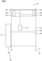
- FIG 1 shows a schematic representation of a motor vehicle 101 according to an embodiment from above.
- Motor vehicle 101 is, for example, a truck with a towing vehicle 101 and a trailer 109.
- the motor vehicle is a bus and/or passenger car, in particular with a trailer 109.
- the motor vehicle 101 has a camera monitor system 100 as a mirror replacement system.
- the camera monitor system 100 has a camera 102 on each side 106 , 107 of the motor vehicle 101 .
- the cameras 102 each serve to record the surroundings of the respective associated side 106, 107.
- several cameras are provided on each side 106, 107, for example two cameras or more.
- the camera 102 is only arranged on one side of the sides 106, 107.
- the camera monitor system 100 has two monitors 104, each of which is assigned to one of the sides 106, 107.
- a section of the environment 105 on the page 106, which is recorded by the camera 102, is displayed on the assigned monitor 104 as an overall image 400.
- the overall image 400 differs on the two monitors 104.
- the overall image 400 on the monitor 104 is set up in particular to display a mirror image of a conventional exterior mirror, in particular to display further sections from the surroundings 105 that cannot be imaged using conventional exterior mirrors.
- a device 110 is provided to which the cameras 102 and the monitors 104 are signal-coupled.
- the device 110 is set up to control both the cameras 102 and the monitors 104 .
- device 110 is a control unit or part of a control unit of motor vehicle 101.
- the image of the camera 102 is transformed so that when the towing vehicle 108 and the trailer 109 are aligned straight, an im Overall image 400 shown field of view aligned with the trailer 109.
- An area of interest 111 is provided adjacent to the tag 109 .
- the area of interest 111 is an area in the environment 105 that is of particular interest to a user of the motor vehicle 101 during operation, for example when maneuvering.
- the area of interest 111 is predetermined to be adjacent to the trailer 109 and specifically at a trailing edge 112 of the trailer 109 .
- the portion of the overall image 400 that is covered by the tag 109 is kept as small and constant as possible.
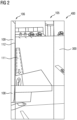
- figure 2 shows an overall image 400 according to an embodiment.
- the image of the camera 102 is transformed in such a way that the trailer 109 is only shown on the left edge.
- the area of interest 111 is represented in an image area 301 .
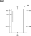
- the overall image 400 is divided into image areas 301 to 306, as in figure 3 shown.
- the enlargement or the Compression and distortion of the representation of the surroundings 105 in the overall image 400 is different for each image area 301 to 306.
- the environment in the transformed image 300 is greatly compressed in the image area 305 so that the trailer 109 takes up as little space as possible in the overall image 400.
- the image area 301 which borders on the image area 305, can thus depict the environment 105 with the conventional magnification, without the trailer 109 being displayed in the image area 301 or without the depiction of the trailer 109 in the image area 301 taking up too much space.
- the area of interest 111 is thus always displayed in the image area 301 .
- the image area 301 with the high magnification depicts the trailer 109 at the edge and otherwise the area of interest 111 and other parts of the environment 105. With a large articulation angle between the towing vehicle 108 and the trailer 109, the trailer 109 would conventionally cover the image area 301 almost completely. The area 301 is therefore shifted in the transformed image 300 and the image area 305 is also shown with a different magnification than the image area 301 .
- image areas 302 and 304 are much more compressed in the horizontal direction than image areas 301 and 303.
- Image areas 303 and 304 are, for example, significantly more compressed in the vertical direction than image areas 301 and 302.
- the input images for image areas 301 and 302 taken with a camera with a telephoto lens.
- the input images for the image areas 303 and 304 are recorded, for example, by a camera with a wide-angle lens.
- the transformed image 300 is composed of the input images from the two cameras.
- the legal field of vision classes 2, 4 and 5 can be mapped and in particular other areas from the environment 105 are mapped.
- the legal field of view class 2 is represented in the image areas 301 and 305, for example.
- the area of interest 111 is specified, for example, relative to the motor vehicle 101 , in particular relative to the trailer 109 .
- Other options for specifying the area of interest 111 are also possible.
- trailer edge detection is carried out from image information from camera 102 and vehicle data.
- trailer position provision is also possible via a system input such as CAN, for example the articulation angle between towing vehicle 108 and trailer 109 .
- a manual selection of the area of interest 111 is also possible, for example the driver of the motor vehicle 101 selects the area of interest 111 with an input device such as a joystick, a touchscreen or a gaze sensor or other input devices.
- the camera field of view is tracked in the individual areas 301 to 306. Even if the area of interest 111 shifts in the input camera image, ie migrates to the right, for example, the area of interest 111 is still displayed in the image area 301 in the transformed image 300 . In particular, the image area 301 is changed for this purpose. In particular, the position of the image area 301 in the transformed image is changed. In particular, the position of the image area 301 in the overall image 400 is changed.
- the area cut out of the input image is changed in such a way that the trailer rear edge 112 is still displayed almost at the edge in the transformed image 300 and the area of interest 111 is still displayed is displayed in the image area 301 .
- Trailer trailing edge 112 is shown in image area 305, which is a different magnification from image area 301 having. It is thus possible to display the tag 109 in the transformed image 300 in a highly compressed manner and to display the area of interest 111 sufficiently large with a desired enlargement.
- the image area 301 in the overall image 400 is shifted to the right, for example, in order to continue to realize a continuous transition to the image area 302 and also to be able to display the entire input image on the monitor 104 even when the trailer 109 is articulated relative to the towing vehicle 108.
- new image areas 305 and 306 are displayed in the transformed image 300 to the left of the image area 301 and to the left of the image area 303, which in comparison to the image areas 301 and 303 are much more horizontally compressed.
- the compression in image area 305 is greater by a factor of 5 than the compression in image area 301.
- a vertical shift is also possible as an alternative or in addition. Accordingly, additional image areas are then displayed above image areas 301 and 303, in which the environment 105 is displayed more compressed in the vertical direction than in image areas 301 and 302 or 305.
- the transition between two immediately adjacent image areas is designed to be as continuous as possible.
- the compression factor between the image areas does not change abruptly from one pixel to the neighboring pixel, but continuously over several pixels.
- the image areas 301 to 306 can be tracked accordingly.
- the input image is distorted or equalized, for example lens-equalized, before the transformation.
- the image is composed of several different camera input images before the transformation or is stitched.
- the input image of a first camera is used for the image areas 301, 302 and 305 and the input image of a second camera is used for the image areas 303, 304 and 306.
- the overall image 400 on the monitor 104 always shows the largest possible portion of the surroundings 105 that is not covered by a display of the trailer 109 . This simplifies maneuvering in particular, for example when parking.
- Objects at the end of trailer 109 are seen better in image area 301 due to the magnification.
- the area in the vicinity of the motor vehicle 101 is displayed enlarged in the image area 301 and is therefore displayed on the monitor 104 with as little compression as possible. Due to the possibility of manually selecting the area of interest 111, the entire image information of the camera 102 is made accessible to the driver, in particular also the outer areas of the image of the camera 102 in high resolution.
- the field of view that is displayed on the monitor 104 of the camera-monitor system 100 is improved in the case of strong articulation angles between the towing vehicle 108 and the trailer 109.
Description
Die Erfindung betrifft ein Verfahren zum Betreiben eines Kamera-Monitor-Systems für ein Kraftfahrzeug, insbesondere für einen Lastkraftwagen. Die Erfindung betrifft weiterhin eine Vorrichtung, die dazu ausgebildet ist, das Verfahren durchzuführen.The invention relates to a method for operating a camera monitor system for a motor vehicle, in particular for a truck. The invention also relates to a device that is designed to carry out the method.
Kraftfahrzeuge, beispielsweise Lastkraftwagen und Busse, weisen herkömmlich Außenspiegel auf. Es sind auch Spiegelersatzsysteme bekannt, bei denen mittels einer Kamera und eines Monitors die Sichtbereiche der üblichen Außenspiegel abgebildet werden. Solche Spiegelersatzsysteme werden auch als Kamera-Monitor-Systeme bezeichnet.Motor vehicles, such as trucks and buses, conventionally have exterior mirrors. Mirror replacement systems are also known, in which the visible areas of the usual exterior mirrors are imaged by means of a camera and a monitor. Such mirror replacement systems are also referred to as camera monitor systems.
Ein Verfahren und eine Vorrichtung zum Betreiben eines Kamera-Monitor-Systems ist beispielsweise aus der
Die
Die
Die
Die
Die
Es ist wünschenswert, ein Verfahren zum Betreiben eines Kamera-Monitor-Systems für ein Kraftfahrzeug anzugeben, das einen zuverlässigen Betrieb ermöglicht. Es ist weiterhin wünschenswert, eine Vorrichtung zum Betreiben eines Kamera-Monitor-Systems anzugeben, die einen verlässlichen Betrieb ermöglicht.It is desirable to specify a method for operating a camera monitor system for a motor vehicle that enables reliable operation. It is also desirable to specify a device for operating a camera monitor system that enables reliable operation.
Die Erfindung zeichnet sich aus durch ein Verfahren gemäß Anspruch 1 zum Betreiben eines Kamera-Monitor-Systems für ein Kraftfahrzeug sowie durch eine korrespondierende Vorrichtung gemäß Anspruch 7, die ausgebildet ist, das Verfahren auszuführen.The invention is characterized by a method according to claim 1 for operating a camera monitor system for a motor vehicle and by a corresponding device according to claim 7, which is designed to carry out the method.
Gemäß der Erfindung weist das Kamera-Monitor-System eine Kamera auf, die einer Längsseite des Kraftfahrzeugs zugeordnet ist. Die Kamera ist dazu ausgebildet, ein Bild einer Umgebung des Kraftfahrzeugs bereitzustellen.According to the invention, the camera-monitor system has a camera that is assigned to a longitudinal side of the motor vehicle. The camera is designed to provide an image of the surroundings of the motor vehicle.
Ein Interessensbereich in der Umgebung wird vorgegeben. Das Bild der Kamera wird zu einem transformierten Bild transformiert, sodass der Interessensbereich in dem transformierten Bild in einem vorgegebenen Bildbereich angeordnet ist, unabhängig von einer Veränderung der Lage des Interessensbereichs in der Umgebung. Der vorgegebene Bildbereich weist eine vorgegebene Vergrößerung auf. Der Interessensbereich wird in dem transformierten Bild insbesondere mit gleichbleibender Vergrößerung dargestellt, unabhängig von einer Veränderung der Lage des Interessensbereichs in der Umgebung.An area of interest in the area is given. The image from the camera is transformed into a transformed image, so that the area of interest in the transformed image is located in a predetermined image area regardless of a change in the location of the area of interest in the environment. The predetermined image area has a predetermined magnification. In particular, the area of interest is displayed in the transformed image with the same magnification, regardless of a change in the position of the area of interest in the environment.
Mittels des Kamera-Monitor-Systems ist es möglich, die Umgebung des Kraftfahrzeugs auf einem Monitor des Kamera-Monitor-Systems für einen Fahrer des Kraftfahrzeugs darzustellen, sodass auf herkömmliche Außenspiegel verzichtet werden kann. Bei Kraftfahrzeugen, die einen Anhänger aufweisen, kann es zu starken Knickwinkeln zwischen dem Zugfahrzeug und dem Anhänger kommen, beispielsweise bei Rangiermanövern, insbesondere bei einer Rückwärtsfahrt. Die Anhängerhinterkante bewegt sich dann in Richtung eines mittleren Bereichs des Bildes. Um zu vermeiden, dass ein Großteil des auf dem Monitor dargestellten Bildes lediglich eine Seitenfläche des Anhängers abbildet, wird das Bild der Kamera entsprechend transformiert.Using the camera-monitor system, it is possible to display the surroundings of the motor vehicle on a monitor of the camera-monitor system for a driver of the motor vehicle, so that conventional exterior mirrors can be dispensed with. In motor vehicles that have a trailer, severe articulation angles can occur between the towing vehicle and the trailer, for example when maneuvering, especially when reversing. The trailer trailing edge then moves towards a central area of the image. In order to avoid that a large part of the image displayed on the monitor only depicts one side of the trailer, the image from the camera is transformed accordingly.
Der Interessensbereich ist beispielsweise ein Bereich unmittelbar neben dem Anhänger. Der Interessensbereich entspricht beispielsweise der gesetzlichen Sichtfeldklasse 2, wenn Anhänger und Zugfahrzeug gerade zueinander ausgerichtet sind. Der Interessensbereich ist beispielsweise ein Teil der gesetzlichen Sichtfeldklasse 2, wenn Anhänger und Zugfahrzeug gerade zueinander ausgerichtet sind. Wenn das Zugfahrzeug und der Anhänger zueinander geknickt sind, verschiebt sich der Interessensbereich entsprechend einem Knickwinkel zwischen dem Zugfahrzeug und dem Anhänger. Im transformierten Bild wird der Interessensbereich weiterhin in dem vorgegebenen Bildbereich dargestellt. Hierfür wird beispielsweise im transformierten Bild der Anhänger stärker gestaucht dargestellt als die Umgebung neben dem Anhänger. Somit ist vermeidbar, dass der Anhänger auch bei starken Knickwinkeln einen ungewünscht großen Bereich des im Monitor dargestellten transformierten Bildes einnimmt. Auch wenn sich in der Umgebung der Interessensbereich verschiebt, weil beispielsweise der Anhänger ausschert, wird das Bild so transformiert, dass eine ähnliche Bildaufteilung wie bei einer geraden Ausrichtung des Zugfahrzeugs und des Anhängers bestehen bleibt.For example, the area of interest is an area immediately adjacent to the trailer. The area of interest corresponds, for example, to the statutory field of vision class 2 when the trailer and towing vehicle are aligned straight to one another. For example, the area of interest is part of the statutory Class 2 field of vision when the trailer and tow vehicle are in straight line with each other. When the tow vehicle and trailer are articulated relative to one another, the area of interest shifts according to an articulation angle between the tow vehicle and trailer. In the transformed image, the area of interest is still represented in the specified image area. For this purpose, for example, the trailer is shown more compressed in the transformed image than the surroundings next to the trailer. It is thus avoidable that the trailer covers an undesirably large area of what is displayed on the monitor, even in the case of strong articulation angles transformed image occupies. Even if the area of interest shifts in the surrounding area, for example because the trailer swerves, the image is transformed in such a way that the image layout remains similar to when the towing vehicle and trailer are aligned in a straight line.
Gemäß der Erfindung umfasst das Vorgeben des Interessensbereichs ein Ermitteln eines vorgegebenen Bildinhalts, beispielsweise der Anhängerhinterkante. Alternativ oder zusätzlich werden Fahrzeugdaten ermittelt, um den Interessensbereich vorzugeben. Dies kann eine Anhängerpositionsbereitstellung über einen Systemeingang wie CAN umfassen oder anderweitige Daten, die im Steuersystem des Kraftfahrzeugs vorliegen. Alternativ oder zusätzlich wird der Interessensbereich mittels einer Eingabevorrichtung vorgegeben, insbesondere vom Nutzer des Kraftfahrzeugs. Die Eingabevorrichtung umfasst beispielsweise einen Joystick, einen Touchscreen und/oder eine Blickerfassung. Somit wird dem Nutzer des Kraftfahrzeugs ermöglicht, einen Bereich in der Umgebung vorzugeben, der stets in dem vorgegebenen Bildbereich des transformierten Bildes dargestellt werden soll und insbesondere nicht von dem Anhänger überdeckt werden soll.According to the invention, specifying the area of interest includes determining a specified image content, for example the rear edge of the trailer. Alternatively or additionally, vehicle data is determined in order to specify the area of interest. This may include trailer location provision via a system input such as CAN, or other data present in the motor vehicle's control system. Alternatively or additionally, the area of interest is specified using an input device, in particular by the user of the motor vehicle. The input device includes, for example, a joystick, a touchscreen and/or a gaze sensor. This enables the user of the motor vehicle to specify an area in the environment that is always to be displayed in the specified image area of the transformed image and, in particular, is not to be covered by the trailer.
Das Bild wird so transformiert, dass vorgegebene Bereiche der Umgebung im transformierten Bild unterschiedlich stark vergrößert in vorgegebenen Bildbereichen abgebildet werden. Die jeweiligen Positionen der Bildbereiche in dem transformierten Bild werden in Abhängigkeit von der Veränderung der Lage des Interessensbereichs in der Umgebung verändert. Beispielsweise wird ein Bildbereich mit schwacher horizontaler und vertikaler Stauchung, der zumindest teilweise die gesetzliche Sichtfeldklasse 2 abdeckt, im transformierten Bild in Richtung der Mitte des Bildes horizontal verschoben. Auch eine vertikale Verschiebung ist möglich. Entsprechend werden bei horizontaler Verschiebung die Bereiche neben dem verschobenen Bereich stärker horizontal gestaucht. Insgesamt bleibt so ein Anteil der dargestelltenThe image is transformed in such a way that predetermined areas of the environment are reproduced in predetermined image areas enlarged to different extents in the transformed image. The respective positions of the image areas in the transformed image are changed depending on the change in the position of the area of interest in the environment. For example, an image area with weak horizontal and vertical compression, which at least partially covers the legal field of view class 2, is shifted horizontally in the transformed image towards the center of the image. A vertical shift is also possible. Accordingly, in the case of a horizontal shift, the areas next to the shifted area are more horizontally compressed. Overall, a proportion of those shown remains
Umgebung zum Anteil des dargestellten Kraftfahrzeugs in dem transformierten Bild nahezu gleich, insbesondere in dem Bildbereich mit schwacher Stauchung.Surroundings are almost the same as the proportion of the motor vehicle shown in the transformed image, particularly in the image area with weak compression.
Gemäß zumindest einer Ausführungsform wird die Vergrößerung in dem Bildbereich, der unmittelbar an den Bildbereich angrenzt, der den Interessensbereich abbildet, verändert, wenn sich die Position der Bildbereiche verändert. Dieser Bildbereich ist insbesondere der Bildbereich, der auch einen Teil des Anhängers des Kraftfahrzeugs abbildet. Die Umgebung wird in diesem Bildbereich stark horizontal gestaucht. Somit ist es möglich, den angrenzenden Bildbereich, der den Interessensbereich zumindest teilweise abbildet, so im transformierten Bild abzubilden, dass der Interessensbereich in dem vorgegebenen Bildbereich angeordnet ist.According to at least one embodiment, the magnification in the image area immediately adjacent to the image area imaging the area of interest is changed as the position of the image areas changes. This image area is in particular the image area that also depicts part of the trailer of the motor vehicle. The surroundings in this area of the image are compressed horizontally. It is thus possible to map the adjoining image area, which at least partially maps the area of interest, in the transformed image in such a way that the area of interest is arranged in the predetermined image area.
Gemäß zumindest einer Ausführungsform wird das Bild vor dem Transformieren entzerrt. Das Eingangsbild der Kamera wird beispielsweise so entzerrt, dass bekannte Verzerrungen aufgrund von verwendeten Linsen ausgeglichen werden.According to at least one embodiment, the image is rectified before the transformation. For example, the camera's input image is corrected in such a way that known distortions due to the lenses used are compensated for.
Gemäß zumindest einer Ausführungsform wird das Bild aus mehreren Eingangsbildern zusammengesetzt. Beispielsweise weist das Kamera-Monitor-System zwei Kameras auf, die der gemeinsamen Längsseite des Kraftfahrzeugs zugeordnet sind, und die jeweils dazu ausgebildet sind, ein Bild der Umgebung des Kraftfahrzeugs bereitzustellen, wobei die abgebildete Umgebung der Bilder teilweise überlappt.In accordance with at least one embodiment, the image is composed of a plurality of input images. For example, the camera-monitor system has two cameras that are assigned to the common longitudinal side of the motor vehicle and that are each designed to provide an image of the area surrounding the motor vehicle, with the imaged area surrounding the images partially overlapping.
Das Bild wird beispielsweise aus Eingangsbildern der beiden Kameras zusammengesetzt. Beispielsweise wird eine Kamera mit einer hohen Brennweite und einem geringen Sichtwinkel verwendet, beispielsweise mit einer Telelinse. Diese Kamera dient zur Abbildung einer Umgebung neben und hinter dem Kraftfahrzeug. Beispielsweise wird eine zweite Kamera verwendet, die eine große Brennweite und einen großen Sichtwinkel aufweist, beispielsweise mit einer Weitwinkellinse. Diese dient beispielsweise dazu, einen Bereich am vorderen Eck des Kraftfahrzeugs beziehungsweise des Zugfahrzeugs aufzunehmen, beispielsweise um die gesetzliche Sichtfeldklasse 5 am Monitor des Kamera-Monitor-Systems abzubilden.For example, the image is composed of input images from the two cameras. For example, a camera with a long focal length and a small angle of view is used, for example with a telephoto lens. This camera is used to image an environment next to and behind the motor vehicle. For example, a second camera is used which has a large focal length and a large angle of view, for example with a wide-angle lens. This serves, for example, to record an area at the front corner of the motor vehicle or the towing vehicle, for example in order to display the statutory field of view class 5 on the monitor of the camera-monitor system.
Die Vorrichtung für das Kraftfahrzeug, die ausgebildet ist, das Verfahren gemäß zumindest einer Ausführungsform durchzuführen, ist beispielsweise Teil eines Steuergeräts für das Kraftfahrzeug (englisch: ECU, electronic control unit).The device for the motor vehicle, which is designed to carry out the method according to at least one embodiment, is, for example, part of a control unit for the motor vehicle (ECU, electronic control unit).
Vorteile, Merkmale und Weiterbildungen, die für das Verfahren beschrieben sind, gelten auch für die Vorrichtung und umgekehrt.Advantages, features and developments that are described for the method also apply to the device and vice versa.
Weitere Vorteile, Merkmale und Weiterbildungen ergeben sich aus den nachfolgenden, in Verbindung mit den Figuren erläuterten Beispielen. Gleiche, gleichartige und gleichwirkende Elemente können figurenübergreifend mit den gleichen Bezugszeichen versehen sein.Further advantages, features and developments result from the following examples explained in connection with the figures. Elements that are the same, of the same type and have the same effect can be provided with the same reference symbols across the figures.
Es zeigen:
-
Figur 1 eine schematische Darstellung eines Kraftfahrzeugs mit einem Kamera-Monitor-System gemäß einem Ausführungsbeispiel, -
Figur 2 eine schematische Darstellung eines Gesamtbildes gemäß einem Ausführungsbeispiel und -
Figur 3 eine schematische Darstellung von Bildbereichen im transformierten Bild gemäß einem Ausführungsbeispiel.
-
figure 1 a schematic representation of a motor vehicle with a camera monitor system according to an embodiment, -
figure 2 a schematic representation of an overall picture according to an embodiment and -
figure 3 a schematic representation of image areas in the transformed image according to an embodiment.
Das Kraftfahrzeug 101 weist ein Kamera-Monitor-System 100 als Spiegelersatzsystem auf. Das Kamera-Monitor-System 100 weist je Seite 106, 107 des Kraftfahrzeugs 101 eine Kamera 102 auf. Die Kameras 102 dienen jeweils dazu, eine Umgebung der jeweiligen zugeordneten Seite 106, 107 aufzunehmen. Gemäß weiteren Ausführungsbeispielen sind je Seite 106, 107 mehrere Kameras vorgesehen, beispielsweise zwei Kameras oder mehr. Gemäß weiteren Ausführungsbeispielen ist die Kamera 102 lediglich an einer Seite der Seiten 106, 107 angeordnet.The
Das Kamera-Monitor-System 100 weist zwei Monitore 104 auf, die jeweils einer der Seiten 106, 107 zugeordnet sind. Im Betrieb wird ein Ausschnitt der Umgebung 105 auf der Seite 106, der von der Kamera 102 aufgezeichnet wird, auf dem zugeordneten Monitor 104 als Gesamtbild 400 dargestellt. Auf dem Monitor 104, der der Seite 107 zugeordnet ist, wird ein Ausschnitt aus der Umgebung 105 als Gesamtbild 400 dargestellt, das mittels der Kamera 102 aufgezeichnet wird, die der Seite 107 zugeordnet ist.The
Somit unterscheidet sich das Gesamtbild 400 auf den beiden Monitoren 104.Thus, the
Das Gesamtbild 400 auf dem Monitor 104 ist insbesondere dazu eingerichtet, ein Spiegelbild eines herkömmlichen Außenspiegels darzustellen, insbesondere weitere Ausschnitte aus der Umgebung 105 darzustellen, die mit herkömmlichen Außenspiegeln nicht abbildbar sind.The
Eine Vorrichtung 110 ist vorgesehen, mit der die Kameras 102 und die Monitore 104 signaltechnisch gekoppelt sind. Die Vorrichtung 110 ist eingerichtet, sowohl die Kameras 102 als auch die Monitore 104 zu steuern. Beispielsweise ist die Vorrichtung 110 ein Steuergerät oder ein Teil eines Steuergeräts des Kraftfahrzeugs 101.A
Das Bild der Kamera 102 wird so transformiert, dass bei gerader Ausrichtung des Zugfahrzeugs 108 und des Anhängers 109 ein im Gesamtbild 400 dargestellter Sichtbereich mit dem Anhänger 109 fluchtet. Neben dem Anhänger 109 ist ein Interessensbereich 111 vorgegeben. Beispielsweise ist der Interessensbereich 111 ein Bereich in der Umgebung 105, der für einen Nutzer des Kraftfahrzeugs 101 im Betrieb von besonderem Interesse ist, beispielsweise bei Rangiermanövern. Der Interessensbereich 111 ist beispielsweise so vorgegeben, dass er neben dem Anhänger 109 und insbesondere an einer Hinterkante 112 des Anhängers 109 liegt.The image of the
Bei Rangiermanövern, insbesondere bei einer Rückwärtsfahrt des Kraftfahrzeugs 101, kann es zu starken Knickwinkeln zwischen dem Zugfahrzeug 108 und dem Anhänger 109 kommen. Die Anhängerhinterkante 112 bewegt sich dann beispielsweise nach rechts. Somit würde herkömmlich ein Bildbereich des Gesamtbilds 400, der bei gerader Ausrichtung des Anhängers 109 zum Zugfahrzeug 108 den Interessenbereich 111 stark vergrößert darstellt, zum Großteil oder vollständig von der Längsseite des Anhängers 109 verdeckt werden. Dieser Bereich des Gesamtbilds wird damit weniger nützlich für den Fahrer des Kraftfahrzeugs 101.During shunting maneuvers, in particular when
Um den Interessensbereich 111 unabhängig von dem Knickwinkel zwischen dem Zugfahrzeug 108 und dem Anhänger 109 im Gesamtbild 400 stets zuverlässig abzubilden und den Anteil im Gesamtbild 400 möglichst groß zu halten, der für den Fahrer nützliche Informationen umfasst, wird die Aufteilung und die Vergrößerung in unterschiedlichen Bildbereichen des Gesamtbilds 400 im Betrieb angepasst. Somit wird der Anteil im Gesamtbild 400, der von dem Anhänger 109 bedeckt wird, möglichst klein und konstant gehalten.In order to always reliably map the area of
Das Gesamtbild 400 ist in Bildbereiche 301 bis 306 unterteilt, wie in
Bei gerader Ausrichtung zwischen dem Anhänger 109 und dem Zugfahrzeug 108 ist es möglich, auf den Bildbereich 305 zu verzichten. Der Bildbereich 301 mit der starken Vergrößerung bildet den Anhänger 109 am Rand ab und ansonsten den Interessensbereich 111 und weitere Teile der Umgebung 105. Bei einem großen Knickwinkel zwischen dem Zugfahrzeug 108 und dem Anhänger 109 würde herkömmlich der Anhänger 109 den Bildbereich 301 fast vollständig verdecken. Daher wird der Bereich 301 im transformierten Bild 300 verschoben und zusätzlich der Bildbereich 305 mit einer zum Bildbereich 301 unterschiedlichen Vergrößerung dargestellt.If the
Beispielsweise sind die Bildbereiche 302 und 304 deutlich stärker in horizontaler Richtung gestaucht als die Bildbereiche 301 und 303. Die Bildbereiche 303 und 304 sind beispielsweise deutlich stärker in vertikaler Richtung gestaucht als die Bildbereiche 301 und 302. Beispielsweise werden die Eingangsbilder für die Bildbereiche 301 und 302 mit einer Kamera mit Telelinse aufgenommen. Die Eingangsbilder für die Bildbereiche 303 und 304 werden beispielsweise von einer Kamera mit Weitwinkellinse aufgenommen. Das transformierte Bild 300 wird aus den Eingangsbildern der beiden Kameras zusammengesetzt. Somit können die gesetzlichen Sichtfeldklassen 2, 4 und 5 abgebildet werden und insbesondere weitere Bereiche aus der Umgebung 105 abgebildet werden. Die gesetzliche Sichtfeldklasse 2 wird beispielsweise in den Bildbereichen 301 und 305 dargestellt.For example,
Der Interessensbereich 111 ist beispielsweise relativ zum Kraftfahrzeug 101, insbesondere relativ zum Anhänger 109, vorgegeben. Auch andere Möglichkeiten den Interessensbereich 111 vorzugeben sind möglich. Beispielsweise wird eine Anhängerkantenerkennung aus Bildinformationen der Kamera 102 und Fahrzeugdaten durchgeführt. Es ist auch möglich, dass eine Anhängerpositionsbereitstellung über einen Systemeingang wie CAN beispielsweise den Knickwinkel zwischen dem Zugfahrzeug 108 und dem Anhänger 109 bereitstellt. Alternativ oder zusätzlich ist auch eine manuelle Auswahl des Interessensbereichs 111 möglich, beispielsweise wählt der Fahrer des Kraftfahrzeugs 101 den Interessensbereich 111 mit einer Eingabevorrichtung wie einem Joystick, einem Touchscreen oder einer Blickerfassung oder anderen Eingabevorrichtungen.The area of
In Abhängigkeit von der Information über die relative Ausrichtung des Anhängers 109 zum Zugfahrzeug 108 wird das Kamerasichtfeld in den einzelnen Bereichen 301 bis 306 nachgeführt. Auch wenn sich der Interessensbereich 111 im Eingangskamerabild verschiebt, also beispielsweise nach rechts wandert, wird im transformierten Bild 300 der Interessensbereich 111 weiterhin im Bildbereich 301 dargestellt. Insbesondere wird hierzu der Bildbereich 301 geändert. Insbesondere wird die Lage des Bildbereichs 301 im transformierten Bild geändert. Insbesondere wird die Lage des Bildbereichs 301 im Gesamtbild 400 geändert. Wenn beispielsweise der Fahrer nach rechts einschert und somit der Fahrzeuganhänger im Eingangsbild in Richtung des Bildbereichs 302 abknickt, wird der aus dem Eingangsbild ausgeschnittene Bereich derart geändert, dass die Anhängerhinterkante 112 im transformierten Bild 300 weiterhin fast ganz am Rand dargestellt wird und der Interessensbereich 111 weiterhin im Bildbereich 301 dargestellt wird. Die Anhängerhinterkante 112 wird im Bildbereich 305 dargestellt, der eine zum Bildbereich 301 andere Vergrößerung aufweist. Somit ist es möglich, den Anhänger 109 im transformierten Bild 300 stark gestaucht darzustellen und den Interessensbereich 111 mit einer gewünschten Vergrößerung ausreichend groß darzustellen.Depending on the information about the relative alignment of the
Der Bildbereich 301 im Gesamtbild 400 wird beispielsweise nach rechts verschoben, um zum einen weiterhin einen kontinuierlichen Übergang zum Bildbereich 302 zu realisieren und zum anderen, um auch bei abgeknicktem Anhänger 109 relativ zum Zugfahrzeug 108 das gesamte Eingangsbild am Monitor 104 anzeigen zu können. Hierfür werden im transformierten Bild 300 links von dem Bildbereich 301 und links vom Bildbereich 303 neue Bildbereiche 305 und 306 angezeigt, die im Vergleich zu den Bildbereichen 301 und 303 deutlich stärker horizontal gestaucht sind. Beispielsweise ist die Stauchung im Bildbereich 305 um den Faktor 5 größer als die Stauchung im Bildbereich 301.The
Zusätzlich zur horizontalen Verschiebung der Darstellung des Interessensbereichs 111 beziehungsweise des Bildbereichs 301 ist alternativ oder zusätzlich auch eine vertikale Verschiebung möglich. Entsprechend werden dann oberhalb der Bildbereiche 301 und 303 zusätzliche Bildbereiche angezeigt, in denen die Umgebung 105 in vertikaler Richtung stärker gestaucht dargestellt wird als in den Bildbereichen 301 und 302 beziehungsweise 305.In addition to the horizontal shifting of the representation of the area of
Der Übergang zwischen jeweils zwei unmittelbar aneinander angrenzenden Bildbereichen wird gemäß Ausführungsformen möglichst kontinuierlich gestaltet. Hierfür ändert sich beispielsweise der Stauchungsfaktor zwischen den Bildbereichen nicht abrupt von einem Pixel zum benachbarten Pixel sondern kontinuierlich über mehrere Pixel hinweg. Auch hier können die Bildbereiche 301 bis 306 entsprechend nachgeführt werden. Gemäß Ausführungsbeispiel wird das Eingangsbild vor dem Transformieren verzerrt oder entzerrt, beispielsweise linsenentzerrt.According to embodiments, the transition between two immediately adjacent image areas is designed to be as continuous as possible. For this purpose, for example, the compression factor between the image areas does not change abruptly from one pixel to the neighboring pixel, but continuously over several pixels. Here, too, the
Es ist auch möglich, dass das Bild vor dem Transformieren aus mehreren verschiedenen Kameraeingangsbildern zusammengesetzt oder gestitcht wird. Beispielsweise wird für die Bildbereiche 301, 302 und 305 das Eingangsbild einer ersten Kamera verwendet und für die Bildbereiche 303, 304 und 306 das Eingangsbild einer zweiten Kamera. Das Gesamtbild 400 am Monitor 104 zeigt stets einen möglichst großen Anteil der Umgebung 105 der nicht von einer Darstellung des Anhängers 109 verdeckt wird. Somit werden insbesondere Rangierfahrten vereinfacht, beispielsweise beim Einparken.It is also possible that the image is composed of several different camera input images before the transformation or is stitched. For example, the input image of a first camera is used for the
Objekte am Ende des Anhängers 109 werden durch die Vergrößerung im Bildbereich 301 besser gesehen. Bei schräg stehendem Anhänger 109 wird die Gefahr für Personen in der Nähe des Kraftfahrzeugs 101 reduziert. Der Bereich in der Nähe des Kraftfahrzeugs 101 wird vergrößert im Bildbereich 301 dargestellt und daher möglichst wenig gestaucht am Monitor 104 dargestellt. Aufgrund der Möglichkeit, den Interessensbereich 111 manuell zu wählen, wird dem Fahrer die gesamte Bildinformation der Kamera 102 zugänglich gemacht, insbesondere auch die Außenbereiche des Bilds der Kamera 102 in hoher Auflösung.Objects at the end of
Insgesamt wird das Sichtfeld, das auf den Monitor 104 des Kamera-Monitor-Systems 100 dargestellt wird, im Fall von starken Knickwinkeln zwischen dem Zugfahrzeug 108 und dem Anhänger 109 verbessert.Overall, the field of view that is displayed on the
Claims (7)
- Method for operating a camera/monitor system (100) for a motor vehicle (101) which is a truck with a tractor (108) and a trailer (109), in which the camera/monitor system (100) comprises a camera (102) assigned to a longitudinal side (106) of the motor vehicle and designed to provide an image of a surround (105) of the motor vehicle (101), comprising:- specifying a region of interest (111) in the surround (105), the specification of the region of interest (111) comprising a determination of a specified image content and/or a determination of vehicle data and/or a specification by means of an input device,- transforming the image of the camera (102) into a transformed image (300) such that the region of interest (111) is arranged in a specified image region (301) in the transformed image (300),wherein the specified image region (301) has a specified magnification, and the region of interest (111) is depicted in the transformed image (300) with unchanging magnification,independently of a change in the position of the region of interest (111) in the surround (105),and wherein the image is transformed such that specified regions of the surround (105) are depicted with different magnifications in specified image regions (301-306) in the transformed image (300), wherein the respective positions of the image regions are changed in the transformed image (300) on the basis of the change of the position of the region of interest (111) in the surround (105),wherein, in the case of a significant articulation angle between the tractor (108) and the trailer (109), the surround in the transformed image (300) is compressed significantly in an image region (305) in which a trailer rear edge (112) is depicted so that the trailer (109) takes up as little space as possible in the overall region, and the image region (301), in which the region of interest (111) is arranged and which is adjacent to the image region (305) in which the trailer rear edge is depicted, can consequently represent the surround (105) with the conventional magnification without the trailer (109) being depicted in the image region (301) in which the region of interest is arranged and/or without the image of the trailer (109) taking up too much space in the image region (301) in which the region of interest is arranged, wherein the region of interest (111) is always depicted in the specified image region (301).
- Method according to Claim 1, wherein the region of interest (111) is a region of the trailer rear edge (112) of the trailer (109) of the motor vehicle (101).
- Method according to Claim 1 or 2, comprising:- transforming the image with a continuously changing compression factor such that a continuous transition is depicted between image regions (301-306) that directly adjoin one another.
- Method according to any of Claims 1 to 3, comprising:- rectifying the image prior to the transformation.
- Method according to any of Claims 1 to 4, comprising:- assembling the image from a plurality of input images.
- Method according to any of Claims 1 to 5, wherein the camera/monitor system (100)has a camera (102) on each side (106, 107) of the motor vehicle,wherein each camera (102) is used to record a surround (105) of the respectively assigned side (106, 107),and wherein two cameras are provided on each side (106, 107), wherein the image is assembled from input images of the two cameras,wherein one camera is used to image a surround next to and behind the motor vehicle and a second camera is used to record a region at the front corner of the motor vehicle.
- Device for motor vehicle which is a truck with a tractor (108) and a trailer (109), the device being designed to carry out a method according to any of Claims 1 to 6.
Applications Claiming Priority (2)
| Application Number | Priority Date | Filing Date | Title |
|---|---|---|---|
| DE102018201217.2A DE102018201217A1 (en) | 2018-01-26 | 2018-01-26 | Method and device for operating a camera monitor system for a motor vehicle |
| PCT/EP2019/050578 WO2019145162A1 (en) | 2018-01-26 | 2019-01-10 | Method and device for operating a video monitoring system for a motor vehicle |
Publications (2)
| Publication Number | Publication Date |
|---|---|
| EP3743311A1 EP3743311A1 (en) | 2020-12-02 |
| EP3743311B1 true EP3743311B1 (en) | 2023-09-06 |
Family
ID=65013706
Family Applications (1)
| Application Number | Title | Priority Date | Filing Date |
|---|---|---|---|
| EP19700377.5A Active EP3743311B1 (en) | 2018-01-26 | 2019-01-10 | Method and device for operating a video monitoring system for a motor vehicle |
Country Status (7)
| Country | Link |
|---|---|
| US (1) | US11433811B2 (en) |
| EP (1) | EP3743311B1 (en) |
| JP (1) | JP2021512536A (en) |
| CA (1) | CA3088462A1 (en) |
| DE (1) | DE102018201217A1 (en) |
| MX (1) | MX2020007754A (en) |
| WO (1) | WO2019145162A1 (en) |
Families Citing this family (1)
| Publication number | Priority date | Publication date | Assignee | Title |
|---|---|---|---|---|
| JP7339821B2 (en) * | 2019-09-12 | 2023-09-06 | サカエ理研工業株式会社 | vehicle display |
Family Cites Families (16)
| Publication number | Priority date | Publication date | Assignee | Title |
|---|---|---|---|---|
| WO2008057285A2 (en) * | 2006-10-27 | 2008-05-15 | Vidient Systems, Inc. | An apparatus for image capture with automatic and manual field of interest processing with a multi-resolution camera |
| IL189251A0 (en) * | 2008-02-05 | 2008-11-03 | Ehud Gal | A manned mobile platforms interactive virtual window vision system |
| WO2011118125A1 (en) | 2010-03-26 | 2011-09-29 | 本田技研工業株式会社 | Device for supporting driving of a vehicle |
| DE102010032411A1 (en) * | 2010-07-27 | 2012-02-02 | Hans Dominik | Environment region monitoring system for vehicle i.e. dragging train, has section selection unit automatically selecting environment region based on parameter, which comprises relative position of towing vehicle and trailer |
| US9264672B2 (en) * | 2010-12-22 | 2016-02-16 | Magna Mirrors Of America, Inc. | Vision display system for vehicle |
| DE102012001835B4 (en) * | 2012-01-31 | 2023-03-02 | Mekra Lang Gmbh & Co. Kg | Vision system for a commercial vehicle for displaying legally required fields of vision of a main mirror and a wide-angle mirror |
| JP5966513B2 (en) * | 2012-03-29 | 2016-08-10 | マツダ株式会社 | Rear side photographing device for vehicle |
| US9558409B2 (en) * | 2012-09-26 | 2017-01-31 | Magna Electronics Inc. | Vehicle vision system with trailer angle detection |
| GB201301950D0 (en) * | 2013-02-04 | 2013-03-20 | Jam Technology Ltd | Vehicle safety system |
| WO2015013311A1 (en) * | 2013-07-22 | 2015-01-29 | Johnson Controls Technology Company | Vehicle imaging system |
| DE102013214368A1 (en) | 2013-07-23 | 2015-01-29 | Application Solutions (Electronics and Vision) Ltd. | Method and device for reproducing a lateral and / or rear surrounding area of a vehicle |
| DE102014018040A1 (en) * | 2014-12-05 | 2016-06-09 | Mekra Lang Gmbh & Co. Kg | vision system |
| DE102015011536A1 (en) | 2015-09-02 | 2017-03-02 | Man Truck & Bus Ag | Mirror replacement system as a camera monitor system (KMS) of a motor vehicle, in particular a commercial vehicle |
| DE102015218033C5 (en) * | 2015-09-18 | 2022-10-13 | Continental Automotive Technologies GmbH | Method for improving rearward visibility in a motor vehicle |
| DE102016216962B3 (en) * | 2016-09-07 | 2017-12-28 | Continental Automotive Gmbh | Method and control unit for tracking a picture detail |
| US10313584B2 (en) * | 2017-01-04 | 2019-06-04 | Texas Instruments Incorporated | Rear-stitched view panorama for rear-view visualization |
-
2018
- 2018-01-26 DE DE102018201217.2A patent/DE102018201217A1/en active Pending
-
2019
- 2019-01-10 US US16/963,637 patent/US11433811B2/en active Active
- 2019-01-10 WO PCT/EP2019/050578 patent/WO2019145162A1/en unknown
- 2019-01-10 CA CA3088462A patent/CA3088462A1/en active Pending
- 2019-01-10 MX MX2020007754A patent/MX2020007754A/en unknown
- 2019-01-10 EP EP19700377.5A patent/EP3743311B1/en active Active
- 2019-01-10 JP JP2020540592A patent/JP2021512536A/en active Pending
Also Published As
| Publication number | Publication date |
|---|---|
| JP2021512536A (en) | 2021-05-13 |
| WO2019145162A1 (en) | 2019-08-01 |
| US11433811B2 (en) | 2022-09-06 |
| EP3743311A1 (en) | 2020-12-02 |
| MX2020007754A (en) | 2020-09-24 |
| DE102018201217A1 (en) | 2019-08-01 |
| CA3088462A1 (en) | 2019-08-01 |
| US20210061173A1 (en) | 2021-03-04 |
Similar Documents
| Publication | Publication Date | Title |
|---|---|---|
| DE102017130566B4 (en) | Vision system for capturing a vehicle environment and a mirror replacement system for a vehicle with a vision system | |
| EP2865569B1 (en) | Display device for fields of vision of a commercial vehicle | |
| EP3024700B1 (en) | Method and device for reproducing a lateral and/or rear surrounding area of a vehicle | |
| EP2623374B1 (en) | Vision system for commercial vehicles for the display of the statutory fields of view of a main mirror and a wide-angle mirror | |
| DE102012102508B4 (en) | Adjustment method and system of a smart vehicle imaging device | |
| DE10083445B4 (en) | Vehicle reverse monitoring device with a display controller for transforming an input image | |
| EP3012154B1 (en) | Method and device to support a driver of a vehicle combination, in particular a commercial vehicle combination | |
| DE102012025322B4 (en) | Motor vehicle with camera monitor system | |
| DE102014018040A1 (en) | vision system | |
| DE102008045436A1 (en) | Method for determining inclination angle between tractor and trailer for e.g. lorry, involves automatically determining inclination angle based on comparison of detected image with reference images and reference image inclination angle | |
| EP3743312A1 (en) | Video monitoring system and method and device for operating a video monitoring system for a motor vehicle | |
| EP3730346B1 (en) | View system for a vehicle | |
| EP3539826A1 (en) | Driver assistance system and method for a motor vehicle for displaying augmented reality displays | |
| DE102014006153A1 (en) | A method for image display of an indirect field of view in the vehicle environment of a vehicle, in particular a commercial vehicle, with a camera-monitor system | |
| EP3882080A1 (en) | Vision system for a vehicle and method for switching between image areas represented by the vision system | |
| DE102008030104A1 (en) | Vehicle i.e. tractor-trailer, surrounding monitoring method, involves assigning positions of image capturing units and weighing factor to each pixel, and determining overall picture between vehicle elements by taking into inclination angle | |
| DE102007016055A1 (en) | Vehicle i.e. car, surroundings monitoring device for e.g. assisting view of driver, has top view video transformation unit transforming video that is recorded by imaging unit into top view video, and display displaying top view video | |
| EP3743311B1 (en) | Method and device for operating a video monitoring system for a motor vehicle | |
| EP3106349B1 (en) | Vision system for a commercial vehicle for the display of the statutory fields of view of a main mirror and a wide-angle mirror | |
| EP3833576B1 (en) | Surveillance camera system | |
| DE102019133948A1 (en) | Method for driver assistance for a combination of a motor vehicle and a trailer | |
| WO2023284920A1 (en) | Camera system, and method for generating a view using a camera system | |
| DE102018203003A1 (en) | Method and device for operating a camera monitor system for a motor vehicle |
Legal Events
| Date | Code | Title | Description |
|---|---|---|---|
| STAA | Information on the status of an ep patent application or granted ep patent |
Free format text: STATUS: UNKNOWN |
|
| STAA | Information on the status of an ep patent application or granted ep patent |
Free format text: STATUS: THE INTERNATIONAL PUBLICATION HAS BEEN MADE |
|
| PUAI | Public reference made under article 153(3) epc to a published international application that has entered the european phase |
Free format text: ORIGINAL CODE: 0009012 |
|
| STAA | Information on the status of an ep patent application or granted ep patent |
Free format text: STATUS: REQUEST FOR EXAMINATION WAS MADE |
|
| 17P | Request for examination filed |
Effective date: 20200826 |
|
| AK | Designated contracting states |
Kind code of ref document: A1 Designated state(s): AL AT BE BG CH CY CZ DE DK EE ES FI FR GB GR HR HU IE IS IT LI LT LU LV MC MK MT NL NO PL PT RO RS SE SI SK SM TR |
|
| AX | Request for extension of the european patent |
Extension state: BA ME |
|
| DAV | Request for validation of the european patent (deleted) | ||
| DAX | Request for extension of the european patent (deleted) | ||
| STAA | Information on the status of an ep patent application or granted ep patent |
Free format text: STATUS: EXAMINATION IS IN PROGRESS |
|
| 17Q | First examination report despatched |
Effective date: 20220209 |
|
| RAP1 | Party data changed (applicant data changed or rights of an application transferred) |
Owner name: CONTINENTAL AUTOMOTIVE TECHNOLOGIES GMBH |
|
| GRAP | Despatch of communication of intention to grant a patent |
Free format text: ORIGINAL CODE: EPIDOSNIGR1 |
|
| STAA | Information on the status of an ep patent application or granted ep patent |
Free format text: STATUS: GRANT OF PATENT IS INTENDED |
|
| INTG | Intention to grant announced |
Effective date: 20230523 |
|
| GRAS | Grant fee paid |
Free format text: ORIGINAL CODE: EPIDOSNIGR3 |
|
| P01 | Opt-out of the competence of the unified patent court (upc) registered |
Effective date: 20230623 |
|
| GRAA | (expected) grant |
Free format text: ORIGINAL CODE: 0009210 |
|
| STAA | Information on the status of an ep patent application or granted ep patent |
Free format text: STATUS: THE PATENT HAS BEEN GRANTED |
|
| AK | Designated contracting states |
Kind code of ref document: B1 Designated state(s): AL AT BE BG CH CY CZ DE DK EE ES FI FR GB GR HR HU IE IS IT LI LT LU LV MC MK MT NL NO PL PT RO RS SE SI SK SM TR |
|
| REG | Reference to a national code |
Ref country code: GB Ref legal event code: FG4D Free format text: NOT ENGLISH |
|
| REG | Reference to a national code |
Ref country code: CH Ref legal event code: EP |
|
| REG | Reference to a national code |
Ref country code: IE Ref legal event code: FG4D Free format text: LANGUAGE OF EP DOCUMENT: GERMAN |
|
| REG | Reference to a national code |
Ref country code: DE Ref legal event code: R096 Ref document number: 502019009247 Country of ref document: DE |
|
| REG | Reference to a national code |
Ref country code: NL Ref legal event code: FP |
|
| REG | Reference to a national code |
Ref country code: LT Ref legal event code: MG9D Ref country code: SE Ref legal event code: TRGR |
|
| PG25 | Lapsed in a contracting state [announced via postgrant information from national office to epo] |
Ref country code: GR Free format text: LAPSE BECAUSE OF FAILURE TO SUBMIT A TRANSLATION OF THE DESCRIPTION OR TO PAY THE FEE WITHIN THE PRESCRIBED TIME-LIMIT Effective date: 20231207 |
|
| PG25 | Lapsed in a contracting state [announced via postgrant information from national office to epo] |
Ref country code: RS Free format text: LAPSE BECAUSE OF FAILURE TO SUBMIT A TRANSLATION OF THE DESCRIPTION OR TO PAY THE FEE WITHIN THE PRESCRIBED TIME-LIMIT Effective date: 20230906 Ref country code: NO Free format text: LAPSE BECAUSE OF FAILURE TO SUBMIT A TRANSLATION OF THE DESCRIPTION OR TO PAY THE FEE WITHIN THE PRESCRIBED TIME-LIMIT Effective date: 20231206 Ref country code: LV Free format text: LAPSE BECAUSE OF FAILURE TO SUBMIT A TRANSLATION OF THE DESCRIPTION OR TO PAY THE FEE WITHIN THE PRESCRIBED TIME-LIMIT Effective date: 20230906 Ref country code: LT Free format text: LAPSE BECAUSE OF FAILURE TO SUBMIT A TRANSLATION OF THE DESCRIPTION OR TO PAY THE FEE WITHIN THE PRESCRIBED TIME-LIMIT Effective date: 20230906 Ref country code: HR Free format text: LAPSE BECAUSE OF FAILURE TO SUBMIT A TRANSLATION OF THE DESCRIPTION OR TO PAY THE FEE WITHIN THE PRESCRIBED TIME-LIMIT Effective date: 20230906 Ref country code: GR Free format text: LAPSE BECAUSE OF FAILURE TO SUBMIT A TRANSLATION OF THE DESCRIPTION OR TO PAY THE FEE WITHIN THE PRESCRIBED TIME-LIMIT Effective date: 20231207 Ref country code: FI Free format text: LAPSE BECAUSE OF FAILURE TO SUBMIT A TRANSLATION OF THE DESCRIPTION OR TO PAY THE FEE WITHIN THE PRESCRIBED TIME-LIMIT Effective date: 20230906 |
|
| REG | Reference to a national code |
Ref country code: DE Ref legal event code: R081 Ref document number: 502019009247 Country of ref document: DE Owner name: CONTINENTAL AUTOMOTIVE TECHNOLOGIES GMBH, DE Free format text: FORMER OWNER: CONTINENTAL AUTOMOTIVE TECHNOLOGIES GMBH, 30165 HANNOVER, DE |
|
| PGFP | Annual fee paid to national office [announced via postgrant information from national office to epo] |
Ref country code: NL Payment date: 20240119 Year of fee payment: 6 |
|
| PG25 | Lapsed in a contracting state [announced via postgrant information from national office to epo] |
Ref country code: IS Free format text: LAPSE BECAUSE OF FAILURE TO SUBMIT A TRANSLATION OF THE DESCRIPTION OR TO PAY THE FEE WITHIN THE PRESCRIBED TIME-LIMIT Effective date: 20240106 |
|
| RAP4 | Party data changed (patent owner data changed or rights of a patent transferred) |
Owner name: CONTINENTAL AUTOMOTIVE TECHNOLOGIES GMBH |