EP3476109B1 - Commutation des sources audio sans fil - Google Patents
Commutation des sources audio sans fil Download PDFInfo
- Publication number
- EP3476109B1 EP3476109B1 EP17733336.6A EP17733336A EP3476109B1 EP 3476109 B1 EP3476109 B1 EP 3476109B1 EP 17733336 A EP17733336 A EP 17733336A EP 3476109 B1 EP3476109 B1 EP 3476109B1
- Authority
- EP
- European Patent Office
- Prior art keywords
- sink device
- audio
- audio source
- paired
- wireless
- Prior art date
- Legal status (The legal status is an assumption and is not a legal conclusion. Google has not performed a legal analysis and makes no representation as to the accuracy of the status listed.)
- Active
Links
Images


Classifications
-
- H—ELECTRICITY
- H04—ELECTRIC COMMUNICATION TECHNIQUE
- H04R—LOUDSPEAKERS, MICROPHONES, GRAMOPHONE PICK-UPS OR LIKE ACOUSTIC ELECTROMECHANICAL TRANSDUCERS; DEAF-AID SETS; PUBLIC ADDRESS SYSTEMS
- H04R1/00—Details of transducers, loudspeakers or microphones
- H04R1/10—Earpieces; Attachments therefor ; Earphones; Monophonic headphones
- H04R1/1041—Mechanical or electronic switches, or control elements
-
- G—PHYSICS
- G06—COMPUTING; CALCULATING OR COUNTING
- G06F—ELECTRIC DIGITAL DATA PROCESSING
- G06F3/00—Input arrangements for transferring data to be processed into a form capable of being handled by the computer; Output arrangements for transferring data from processing unit to output unit, e.g. interface arrangements
- G06F3/16—Sound input; Sound output
- G06F3/165—Management of the audio stream, e.g. setting of volume, audio stream path
-
- H—ELECTRICITY
- H04—ELECTRIC COMMUNICATION TECHNIQUE
- H04M—TELEPHONIC COMMUNICATION
- H04M1/00—Substation equipment, e.g. for use by subscribers
- H04M1/60—Substation equipment, e.g. for use by subscribers including speech amplifiers
- H04M1/6033—Substation equipment, e.g. for use by subscribers including speech amplifiers for providing handsfree use or a loudspeaker mode in telephone sets
- H04M1/6041—Portable telephones adapted for handsfree use
- H04M1/6058—Portable telephones adapted for handsfree use involving the use of a headset accessory device connected to the portable telephone
- H04M1/6066—Portable telephones adapted for handsfree use involving the use of a headset accessory device connected to the portable telephone including a wireless connection
-
- H—ELECTRICITY
- H04—ELECTRIC COMMUNICATION TECHNIQUE
- H04M—TELEPHONIC COMMUNICATION
- H04M1/00—Substation equipment, e.g. for use by subscribers
- H04M1/72—Mobile telephones; Cordless telephones, i.e. devices for establishing wireless links to base stations without route selection
- H04M1/724—User interfaces specially adapted for cordless or mobile telephones
- H04M1/72403—User interfaces specially adapted for cordless or mobile telephones with means for local support of applications that increase the functionality
- H04M1/72409—User interfaces specially adapted for cordless or mobile telephones with means for local support of applications that increase the functionality by interfacing with external accessories
- H04M1/72412—User interfaces specially adapted for cordless or mobile telephones with means for local support of applications that increase the functionality by interfacing with external accessories using two-way short-range wireless interfaces
-
- H—ELECTRICITY
- H04—ELECTRIC COMMUNICATION TECHNIQUE
- H04R—LOUDSPEAKERS, MICROPHONES, GRAMOPHONE PICK-UPS OR LIKE ACOUSTIC ELECTROMECHANICAL TRANSDUCERS; DEAF-AID SETS; PUBLIC ADDRESS SYSTEMS
- H04R3/00—Circuits for transducers, loudspeakers or microphones
- H04R3/12—Circuits for transducers, loudspeakers or microphones for distributing signals to two or more loudspeakers
-
- H—ELECTRICITY
- H04—ELECTRIC COMMUNICATION TECHNIQUE
- H04R—LOUDSPEAKERS, MICROPHONES, GRAMOPHONE PICK-UPS OR LIKE ACOUSTIC ELECTROMECHANICAL TRANSDUCERS; DEAF-AID SETS; PUBLIC ADDRESS SYSTEMS
- H04R5/00—Stereophonic arrangements
- H04R5/033—Headphones for stereophonic communication
-
- H—ELECTRICITY
- H04—ELECTRIC COMMUNICATION TECHNIQUE
- H04R—LOUDSPEAKERS, MICROPHONES, GRAMOPHONE PICK-UPS OR LIKE ACOUSTIC ELECTROMECHANICAL TRANSDUCERS; DEAF-AID SETS; PUBLIC ADDRESS SYSTEMS
- H04R5/00—Stereophonic arrangements
- H04R5/04—Circuit arrangements, e.g. for selective connection of amplifier inputs/outputs to loudspeakers, for loudspeaker detection, or for adaptation of settings to personal preferences or hearing impairments
-
- H—ELECTRICITY
- H04—ELECTRIC COMMUNICATION TECHNIQUE
- H04W—WIRELESS COMMUNICATION NETWORKS
- H04W4/00—Services specially adapted for wireless communication networks; Facilities therefor
- H04W4/80—Services using short range communication, e.g. near-field communication [NFC], radio-frequency identification [RFID] or low energy communication
-
- H—ELECTRICITY
- H04—ELECTRIC COMMUNICATION TECHNIQUE
- H04W—WIRELESS COMMUNICATION NETWORKS
- H04W76/00—Connection management
- H04W76/10—Connection setup
-
- H—ELECTRICITY
- H04—ELECTRIC COMMUNICATION TECHNIQUE
- H04W—WIRELESS COMMUNICATION NETWORKS
- H04W84/00—Network topologies
- H04W84/18—Self-organising networks, e.g. ad-hoc networks or sensor networks
- H04W84/20—Master-slave selection or change arrangements
-
- H—ELECTRICITY
- H04—ELECTRIC COMMUNICATION TECHNIQUE
- H04M—TELEPHONIC COMMUNICATION
- H04M2250/00—Details of telephonic subscriber devices
- H04M2250/02—Details of telephonic subscriber devices including a Bluetooth interface
-
- H—ELECTRICITY
- H04—ELECTRIC COMMUNICATION TECHNIQUE
- H04R—LOUDSPEAKERS, MICROPHONES, GRAMOPHONE PICK-UPS OR LIKE ACOUSTIC ELECTROMECHANICAL TRANSDUCERS; DEAF-AID SETS; PUBLIC ADDRESS SYSTEMS
- H04R2225/00—Details of deaf aids covered by H04R25/00, not provided for in any of its subgroups
- H04R2225/55—Communication between hearing aids and external devices via a network for data exchange
-
- H—ELECTRICITY
- H04—ELECTRIC COMMUNICATION TECHNIQUE
- H04R—LOUDSPEAKERS, MICROPHONES, GRAMOPHONE PICK-UPS OR LIKE ACOUSTIC ELECTROMECHANICAL TRANSDUCERS; DEAF-AID SETS; PUBLIC ADDRESS SYSTEMS
- H04R2420/00—Details of connection covered by H04R, not provided for in its groups
- H04R2420/03—Connection circuits to selectively connect loudspeakers or headphones to amplifiers
-
- H—ELECTRICITY
- H04—ELECTRIC COMMUNICATION TECHNIQUE
- H04R—LOUDSPEAKERS, MICROPHONES, GRAMOPHONE PICK-UPS OR LIKE ACOUSTIC ELECTROMECHANICAL TRANSDUCERS; DEAF-AID SETS; PUBLIC ADDRESS SYSTEMS
- H04R2420/00—Details of connection covered by H04R, not provided for in its groups
- H04R2420/05—Detection of connection of loudspeakers or headphones to amplifiers
-
- H—ELECTRICITY
- H04—ELECTRIC COMMUNICATION TECHNIQUE
- H04R—LOUDSPEAKERS, MICROPHONES, GRAMOPHONE PICK-UPS OR LIKE ACOUSTIC ELECTROMECHANICAL TRANSDUCERS; DEAF-AID SETS; PUBLIC ADDRESS SYSTEMS
- H04R2420/00—Details of connection covered by H04R, not provided for in its groups
- H04R2420/07—Applications of wireless loudspeakers or wireless microphones
-
- H—ELECTRICITY
- H04—ELECTRIC COMMUNICATION TECHNIQUE
- H04R—LOUDSPEAKERS, MICROPHONES, GRAMOPHONE PICK-UPS OR LIKE ACOUSTIC ELECTROMECHANICAL TRANSDUCERS; DEAF-AID SETS; PUBLIC ADDRESS SYSTEMS
- H04R25/00—Deaf-aid sets, i.e. electro-acoustic or electro-mechanical hearing aids; Electric tinnitus maskers providing an auditory perception
- H04R25/55—Deaf-aid sets, i.e. electro-acoustic or electro-mechanical hearing aids; Electric tinnitus maskers providing an auditory perception using an external connection, either wireless or wired
- H04R25/554—Deaf-aid sets, i.e. electro-acoustic or electro-mechanical hearing aids; Electric tinnitus maskers providing an auditory perception using an external connection, either wireless or wired using a wireless connection, e.g. between microphone and amplifier or using Tcoils
Definitions
- Some wireless communications protocols operate by designating devices as either a master device or a slave device. Thus, in any pair of communicating devices, one device is the master and the other device is the slave. For example, in the Bluetooth® wireless technology standard maintained by the Bluetooth Special Interest Group of Kirkland, Washington, a master device can establish connections with up to seven slave devices simultaneously. However, a slave device can only connect to one master device at a time.
- a master device and its connected slave devices is referred to as a piconet. It is possible for multiple piconets to be linked together, which is referred to as a scatternet.
- Establishing a Bluetooth connection starts in an inquiry phase, in which a device transmits an inquiry request.
- Devices that listen for inquiries are referred to as being in a discoverable state. All devices that receive the inquiry respond with their address.
- a device can become a master device during a paging phase.
- two devices synchronize their clocks.
- One device sends a sequence of paging messages and listens for a response from another device.
- a device that is listening for paging messages is referred to as being in a connectable state. If another device responds, the first device becomes the master device of the connection and the responding device becomes the slave.
- ACL Asynchronous Connection-Less
- the devices After establishing the ACL connection, the devices open a Logical Link Control and Adaption (L2CAP) channel.
- L2CAP Logical Link Control and Adaption
- the devices can use the L2CAP channel to perform service discovery in order to perform pairing and to discover supported profiles and features of the master device.
- two devices may undergo a pairing process.
- the sink device sends a pairing request to the master device.
- the sink device then prompts a user to enter a personal identification number (PIN) at the master device to complete the pairing process.
- PIN personal identification number
- the sink device can store the address of the master device in a list of trusted devices that have successfully been paired with the sink device.
- the list of trusted devices thus maintains an address for each paired master device as well as an associated index for each paired master device.
- the sink device can then skip the pairing process for any master device that occurs in the list of trusted devices.
- the Bluetooth standard defines a number of application profiles that specify services that are offered by a Bluetooth-enabled device.
- a single device can support multiple profiles.
- Common profiles include an Advanced Audio Distribution Profile (A2DP), which defines how audio data can be streamed from one device to another; an Audio Video Remote Control Profile (AVRCP), which provides an interface for controlling televisions and other audio/video equipment; and a Hands Free Profile (HFP), which is used to communicate with hands-free sink devices.
- A2DP Advanced Audio Distribution Profile
- AVRCP Audio Video Remote Control Profile
- HFP Hands Free Profile
- the devices can open one or more L2CAP channels to support one or more of the supported profiles.
- This specification describes a wireless audio output sink device that can switch between multiple audio source devices using dedicated user interface controls.
- a sink device can implement intent-based switching that honors the intent of the user in determining which audio source from which to receive audio data.
- a user can easily and quickly switch between multiple audio source devices with very little user input. After requesting a switch, the user need not provide any additional input to the sink device or any of the source devices to begin receiving audio data at the sink device.
- a sink device can switch between multiple different activities of a single audio source device. A sink device does not switch to other sources when a connected source device becomes unavailable.
- a “sink device” is an audio output device that is configured to wirelessly receive audio data from a source device using a wireless communications protocol.
- Common sink devices include wireless headphone sets and standalone wireless speakers.
- a dedicated user interface control means a user input mechanism that maps user input to a particular source device.
- a dedicated user interface control can be a physical button, toggle, dial, or switch.
- the dedicated user interface control can also be a soft user interface control that corresponds to a particular activated area of a presence-sensitive surface or display.
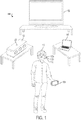
- FIG. 1 is a diagram of an example system 100.
- the system 100 includes two sink devices: a headphone set 110 and a wireless speaker set 120.
- the system 100 also includes three source devices: a mobile phone 130, a laptop computer 140, and a television 150.
- the source devices 130, 140, and 150 are devices that can use a short- to midrange wireless communication protocol, e.g., Bluetooth, to provide audio data to one or more sink devices.
- a short- to midrange wireless communication protocol e.g., Bluetooth
- the wireless headphone set 110 has integrated buttons 112a-c that are dedicated user interface controls for switching between source devices, e.g., the source devices 130, 140, and 150. For example, if a user presses the button 112a, the headphone set 110 can switch to receiving audio data from the mobile phone 130. If the user presses the button 112b, the headphone set 110 can switch to receiving audio data from the laptop computer 140. If the user presses the button 112c, the headphone set 110 can switch to receiving audio data from the television 150.
- buttons 112a-c are dedicated user interface controls for switching between source devices, e.g., the source devices 130, 140, and 150. For example, if a user presses the button 112a, the headphone set 110 can switch to receiving audio data from the mobile phone 130. If the user presses the button 112b, the headphone set 110 can switch to receiving audio data from the laptop computer 140. If the user presses the button 112c, the headphone set 110 can switch to receiving audio data from the television 150.
- the wireless speaker set 120 has another type of integrated user interface control: a toggle button 122.
- the toggle button 122 can be used to cycle through connected source devices. For example, if the wireless speaker set 120 is connected to the television 150, the wireless speaker set 120 can switch to receiving audio data from the mobile phone 130 when the toggle button 122 is pressed.
- FIG. 2 illustrates components of an example sink device 210.
- the sink device 210 has three dedicated user interface controls: a first source button 202, a second source button 204, and a third source button 206.
- the sink device 210 has a switching device table 220 that associates user interface control indexes with addresses of corresponding source devices.
- the sink device 210 also has a trusted device table 230 that associates trusted device indexes with addresses of corresponding source devices.
- a user can associate one of the dedicated user interface controls during a pairing process.
- the sink device 210 can be configured to distinguish user input that requests pairing with a new audio source device and user input that requests switching to a particular audio source device. For example, the sink device 210 can interpret a short press of a button, e.g., less than 1 second, as a request to switch to an audio source device associated with the button and can interpret a long press of the same button, e.g., 1 second or more, as a request to pair with a new audio source device to be associated with the button.
- a user can provide a long press on the second source button 204.
- the sink device 210 interprets this user input as a request to associate the second source button 204 with a new audio source device.
- the sink device 210 then pairs with the new audio source device. This process is described in more detail below with reference to FIG. 3 .
- the sink device 210 After pairing, the sink device 210 considers the paired audio source device to be a trusted device. During state 2, the sink device 210 stores the address of the new audio source device in the trusted device table 230. During state 3, the sink device 210 stores the address of the new audio source device in the switching device table 220, which associates the address of the new audio source device with a user interface control index of the second source button 204.
- the sink device can associate each of the dedicated user interface controls with a particular activity on a source device.
- a single source device can be associated with multiple user interface controls.
- a tablet computer can provide multiple sources of audio information to a sink device that each correspond to a particular activity, e.g., music player audio, cinematic audio, and system notification audio.
- a user can associate each activity with a user interface control, e.g., one of the source buttons 202, 204, or 206.
- a user can associate music player audio with the first source button 202 and cinematic audio with the second source button 204.
- the user can explicitly select the source button corresponding to desired activity.
- the sink device 210 can store a additional column attribute in the switching device table.
- the additional column attribute corresponds to an activity identifier for a particular activity.
- some rows of the switching device table 220 will refer to the same address but different activity identifiers.
- This additional information may need to be configured by software running on the source device that provides an activity identifier to the sink device 210.
- a mobile phone can install an application that enumerates the different activities. Then, during the pairing process, a user can use the application to cause the phone to provide particular activity identifiers to the sink device 210. The sink device 210 then stores the received activity identifiers in the switching device table 220.
- FIG. 3 is a flow chart of an example process for assigning a dedicated user interface control to one of multiple audio source devices.
- the process can be performed by an appropriately programmed wireless audio output device comprising one or more computers.
- the process will be described as being performed by an embedded computer or logic circuitry in a sink device.
- the audio output device will perform the example process for each of multiple master audio source devices.
- the sink device receives user input requesting pairing for a new audio source device (310).
- the sink device determines whether its state is connectable (320). A sink device is in a connectable state when it is listening for paging messages from potential master devices trying to establish connections. If the sink device is in a connectable state, the sink device enters a discoverable state (branch to 360).
- the sink device listens for inquiries from master devices.
- the connectable state and the discoverable state are not mutually exclusive.
- the sink device may already be in the discoverable state.
- the sink device ensures that it is in the discoverable state in order to discover any new audio source devices that are within range.
- the responsiveness of the sink device can be improved by exiting the connectable state so that the sink device is no longer scanning for paging messages.
- the sink device when entering the discoverable state (360), the sink device exits the connectable state.
- the sink device After entering the discoverable state (360), the sink device pairs with the new audio source device (370). To pair with the new audio source device, the sink device enters a discoverable state to provide its address to the new audio source device. The sink device then enters a connectable state to synchronize with the new audio source device. In some implementations, the sink device does not require a pairing code in order to pair with the new audio source device.
- the sink device determines whether its state is discoverable (branch to 330). If so, the sink device is ready to pair with new source devices. Thus, the sink device can then pair with the new audio source device (branch to 380).
- the sink device likely has already has an established connection with a previous master audio source device, and such connection needs to be torn down before pairing with the new audio source device.
- the sink device disconnects all service level connections and all profiles (branch to 340). For example, the sink device can disconnect the ACL and L2CAP connections with the previous master audio source device as well as disconnect all A2DP and AVRCP profiles.
- the sink device will receive a disconnect message from the previous master audio source device (350). Upon receiving the disconnect message, the sink device can then pair with the new audio source device (370).
- the sink device After being paired, the sink device associates the new paired device with the selected user interface control (380). For example, the sink device can directly associate the address of the new paired device with a user interface control index corresponding to the selected user interface control. For example, if the sink devices has multiple buttons, each button can be assigned a respective user interface control index. The sink device can associate each user interface control index with the address of a corresponding paired device in a switching device table.
- Table 1 illustrates an example switching device table that associates user interface control indexes with addresses.
- the sink device can use the switching device table to obtain the address of the new paired device.
- the sink device also maintains a trusted device table that associates trusted device indexes to addresses.
- the standard libraries of some wireless communication protocols maintain a trusted device table.
- the sink device assigns a trusted device index for the new paired device and associates the address of the new paired device with the corresponding trusted device index.
- Subsequent interactions with the wireless protocol stack use the trusted device index as input to the application programming interfaces (APIs) of the standard libraries.
- APIs application programming interfaces
- Table 2 illustrates an example trusted device table that associates trusted device indexes to addresses: TABLE 2 TRUSTED DEVICE INDEX ADDRESS 1 00025b00ff09 2 00025b00ff06 3 00025b00ff01
- the sink device can obtain a trusted device index given a user interface control index by comparing the entries in the tables. This process is described in more detail below with reference to FIG. 7 .
- the sink device can then optionally store the trusted device table and the switching device table in persistent storage integrated with the sink device. By storing the trusted device table and the switching device table in persistent storage, the device need not undergo pairing processes after a restart.
- FIG. 4 illustrates components of an example sink device 410.
- the sink device 410 has three dedicated user interface controls: a first source button 402, a second source button 404, and a third source button 406.
- the sink device 410 has a switching device table 420 that associates user interface control indexes with addresses of corresponding source devices.
- the sink device 410 also has a trusted device table 430 that associates trusted device indexes with addresses of corresponding source devices.
- a user can cause the sink device to switch to a new audio source device by pressing any of the source buttons 402, 404, or 406.
- the user can press the second source button 404.
- the sink device 410 can use a user interface control index corresponding to the selected second source button 404 as an index into the switching device table 420 to obtain the address of the requested audio source device.
- the sink device 410 searches the trusted device table 430 for a matching address. During state 4, after finding the matching address, the sink device 410 obtains the trusted device index of the requested audio source device. The sink device 410 can then use the trusted device index to connect to the requested audio source device.
- the sink device 410 If the sink device 410 was configured to switch between particular activities of a single source device, the sink device 410 will use an activity identifier stored in the switching device table 420 when establishing the connection with the requested audio source device. However, if the sink device 410 is already connected to the audio source device, the sink device 410 may not need to establish a new connection with the requested source device.
- FIG. 5 is a flow chart of an example process for a sink device to switch to a new source device.
- the process can be performed by an appropriately programmed wireless audio output device comprising one or more computers.
- the process will be described as being performed by an embedded computer or logic circuitry in a sink device.
- the sink device pairs with two or more audio source devices (510).
- the sink device can use the process described above with reference to FIGS. 2-3 for each of multiple audio source devices.
- the sink device receives user input requesting to switch from a first paired audio source device to a different second paired audio source device (520).
- the sink device will typically be a slave device of a master/slave connection with the first paired audio source device.
- the sink device can receive the user input at a dedicated user interface control.
- the sink device can also receive the user input as a voice command.
- the sink device can then determine a paired audio source device corresponding to the user input.
- the sink device maintains a switching device table and a separate trusted device table.
- the sink device can then obtain the trusted device index for a particular user input using both tables. To do so, the sink device obtains a user interface control index of the dedicated user interface control.
- the sink device searches a switching device table with the user interface control index to obtain an address of the second paired audio source device. After obtaining the address of the second paired audio source device, the sink device searches a trusted device table to obtain a trusted device index of the second paired audio source device. For example, the system can compare the address of the second paired audio source device with each entry in the trusted device table. Upon finding a matching entry, the sink device can use the trusted device index of the matching entry as the trusted device index of the second paired audio source device.
- the sink device initiates a request to become a master device of a master/slave connection with the second paired audio source device (530). As described above, to become the master device the sink device can send paging messages and wait for a response from the second paired audio source device. The sink device can then establish the connection with the second paired audio source device.
- the sink device can then use the trusted device index to establish a connection with the second paired audio source device. However, the sink device need not use the trusted device index to establish such a connection. In some implementations, the sink device can use the address of the second paired audio source device directly. In addition, the sink device need not use two separate tables to obtain the trusted device index. In some implementations, the sink device can directly associate the user interface control index with a corresponding trusted device index.
- the sink device determines that a master/slave connection is established with the second paired audio source device (540).
- the sink device sends a request to the second paired audio source device to become a slave device of the master/slave connection (550). In other words, the sink device sends a request to exchange roles in the connection with the second paired audio source device.
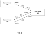
- FIG. 6 illustrates an example switch by a sink device 620 between two source devices 610 and 630.
- the sink device 620 is a slave device of a master/slave connection with the first source device 610.
- the sink device initiates a connection as a master with the second source device 630.
- the sink device 620 requests an exchange, and the sink device 620 becomes the slave device of the connection with the second source device 630.
- the sink device upon exchanging roles, the sink device begins receiving audio input from the second paired audio source device and outputting the received audio input (560). Because the sink device was already paired to multiple master devices, the switch to the second paired audio source device requires no further user input after the initial request. For example, if the user interface control is a button, a user can switch audio source devices by simply pressing the button on the sink device. The sink device then seamlessly switches to the second audio source device without any further input by the user at the sink device or at any of the audio source devices.
- the user interface control is a button
- the sink device has three buttons that are assigned respectively to these three devices.
- the user To listen to the television, the user simply presses a first button on the sink device. The connection is established to the television and the other devices are not impacted.
- the user presses a second button on the sink device.
- the sink device terminates the connection with the television and connects to the tablet computer.
- the television reacts to the disconnection by resuming a previous audio playback state.
- the mobile phone is not impacted.
- the sink device terminates the connection with the tablet computer and connects with the mobile phone.
- FIG. 7 is a flow chart of an example process for a sink device to connect to a new audio source device.
- the process can be performed by an appropriately programmed wireless audio output device comprising one or more computers.
- the process will be described as being performed by an embedded computer or logic circuitry in a sink device.
- the sink device receives user input requesting a switch to an audio source device (710).
- the sink device can receive the user input at a dedicated user interface control.
- the sink device determines a trusted device index for the requested audio source device, e.g., as described above with reference to FIGS. 2-3 . The sink device can then use the trusted device index to interact with the corresponding audio source device.
- the sink device determines whether its state is connectable (720). If so, the sink device cancels all service level connections (branch to 750). In doing so, the sink device clears random access memory space occupied by one or more previous connections.
- the sink device then sends a connection request to the audio source device (770).
- the sink device can initiate the connection as a master device, and then send a request to exchange roles with the audio source device.
- the sink device determines whether its state is discoverable (branch to 730). If so, the sink device enters the connectable state (760) and sends a connection request to the audio source device (770).
- the sink device disconnects all service level connections and profiles (branch to 740) and sends a connection request to the audio source device (770). By disconnecting all service level connections and profiles, the sink device can clear memory that was occupied by one or more previous connections.
- FIG. 8 is a flow chart of an example process for handling disconnections by a sink device.
- the process can be performed by an appropriately programmed wireless audio output device comprising one or more computers.
- the process will be described as being performed by an embedded computer or logic circuitry in a sink device.
- the sink device receives user input selecting a paired audio source device (810). Generally, the sink device will have multiple paired audio source devices. The sink device can store the addresses of the paired audio source devices in a trusted device table as describe above.
- the sink device establishes a connection with the selected audio source device (820).
- the sink device determines that the connection with the audio source device has been lost (830).
- the connection can be lost for any of a number of reasons.
- the audio source device can go out of range, encounter electromagnetic interference, or lose power.
- the sink device waits for the connection with the audio source device to be reestablished without switching to other paired devices (840).
- the intent-based switching mechanism of the sink device means that the sink device waits for the device to reconnect.
- the sink device does not connect to another source device without explicit user input that selects another source device.
- the sink device determines that the audio source device is available again (850). For example, the audio source device can power back on or come back into range.
- the sink device reestablishes the connection with the audio source device (860).
- the sink device can automatically request to establish a connection as a master device and then request to switch roles, as describe above with reference to FIGS. 5-6 .
- the sink device can again receive audio input from the connected audio source device.
- Embodiments of the subject matter and the functional operations described in this specification can be implemented in digital electronic circuitry, in tangibly-embodied computer software or firmware, in computer hardware, including the structures disclosed in this specification and their structural equivalents, or in combinations of one or more of them.
- Embodiments of the subject matter described in this specification can be implemented as one or more computer programs, i.e., one or more modules of computer program instructions encoded on a tangible non-transitory storage medium for execution by, or to control the operation of, data processing apparatus.
- the computer storage medium can be a machine-readable storage device, a machine-readable storage substrate, a random or serial access memory device, or a combination of one or more of them.
- the program instructions can be encoded on an artificially-generated propagated signal, e.g., a machine-generated electrical, optical, or electromagnetic signal, that is generated to encode information for transmission to suitable receiver apparatus for execution by a data processing apparatus.
- data processing apparatus refers to data processing hardware and encompasses all kinds of apparatus, devices, and machines for processing data, including by way of example a programmable processor, a computer, or multiple processors or computers.
- the apparatus can also be, or further include, special purpose logic circuitry, e.g., an FPGA (field programmable gate array) or an ASIC (application-specific integrated circuit).
- the apparatus can optionally include, in addition to hardware, code that creates an execution environment for computer programs, e.g., code that constitutes processor firmware, a protocol stack, a database management system, an operating system, or a combination of one or more of them.
- a computer program which may also be referred to or described as a program, software, a software application, an app, a module, a software module, a script, or code, can be written in any form of programming language, including compiled or interpreted languages, or declarative or procedural languages; and it can be deployed in any form, including as a stand-alone program or as a module, component, subroutine, or other unit suitable for use in a computing environment.
- a program may, but need not, correspond to a file in a file system.
- a program can be stored in a portion of a file that holds other programs or data, e.g., one or more scripts stored in a markup language document, in a single file dedicated to the program in question, or in multiple coordinated files, e.g., files that store one or more modules, sub-programs, or portions of code.
- a computer program can be deployed to be executed on one computer or on multiple computers that are located at one site or distributed across multiple sites and interconnected by a data communication network.
- an “engine,” or “software engine,” refers to a software implemented input/output system that provides an output that is different from the input.
- An engine can be an encoded block of functionality, such as a library, a platform, a software development kit ("SDK”), or an object.
- SDK software development kit
- Each engine can be implemented on any appropriate type of computing device, e.g., servers, mobile phones, headphone sets, portable speakers, tablet computers, notebook computers, music players, e-book readers, laptop or desktop computers, PDAs, smart phones, or other stationary or portable devices, that includes one or more processors and computer readable media. Additionally, two or more of the engines may be implemented on the same computing device, or on different computing devices.
- the processes and logic flows described in this specification can be performed by one or more programmable computers executing one or more computer programs to perform functions by operating on input data and generating output.
- the processes and logic flows can also be performed by special purpose logic circuitry, e.g., an FPGA or an ASIC, or by a combination of special purpose logic circuitry and one or more programmed computers.
- Computers suitable for the execution of a computer program can be based on general or special purpose microprocessors or both, or any other kind of central processing unit.
- a central processing unit will receive instructions and data from a read only memory or a random access memory or both.
- the essential elements of a computer are a central processing unit for performing or executing instructions and one or more memory devices for storing instructions and data.
- the central processing unit and the memory can be supplemented by, or incorporated in, special purpose logic circuitry.
- a computer will also include, or be operatively coupled to receive data from or transfer data to, or both, one or more mass storage devices for storing data, e.g., magnetic, magneto optical disks, or optical disks. However, a computer need not have such devices.
- a computer can be embedded in another device, e.g., a mobile telephone, a personal digital assistant (PDA), a mobile audio or video player, a game console, a Global Positioning System (GPS) receiver, or a portable storage device, e.g., a universal serial bus (USB) flash drive, to name just a few.
- PDA personal digital assistant
- GPS Global Positioning System
- USB universal serial bus
- Computer readable media suitable for storing computer program instructions and data include all forms of non volatile memory, media and memory devices, including by way of example semiconductor memory devices, e.g., EPROM, EEPROM, and flash memory devices; magnetic disks, e.g., internal hard disks or removable disks; magneto optical disks; and CD ROM and DVD-ROM disks.
- semiconductor memory devices e.g., EPROM, EEPROM, and flash memory devices
- magnetic disks e.g., internal hard disks or removable disks
- magneto optical disks e.g., CD ROM and DVD-ROM disks.
- embodiments of the subject matter described in this specification can be implemented on a computer having a display device, e.g., a CRT (cathode ray tube) or LCD (liquid crystal display) monitor, for displaying information to the user and a keyboard and a pointing device, e.g., a mouse or a trackball, by which the user can provide input to the computer.
- a display device e.g., a CRT (cathode ray tube) or LCD (liquid crystal display) monitor
- keyboard and a pointing device e.g., a mouse or a trackball
- Other kinds of devices can be used to provide for interaction with a user as well; for example, feedback provided to the user can be any form of sensory feedback, e.g., visual feedback, auditory feedback, or tactile feedback; and input from the user can be received in any form, including acoustic, speech, or tactile input.
Claims (15)
- Procédé comprenant :la réception, au niveau d'un dispositif collecteur audio sans fil, d'une entrée d'utilisateur sélectionnant une commande d'interface utilisateur du dispositif collecteur audio sans fil, la commande d'interface utilisateur correspondant à un d'une pluralité de dispositifs de source audio jumelés, dans lequel le dispositif collecteur audio sans fil est un dispositif esclave d'une première connexion maître/esclave avec un premier dispositif de source audio jumelé de la pluralité de dispositifs de source audio jumelés ;l'identification, par le dispositif collecteur audio sans fil, d'un second dispositif de source audio jumelé correspondant à la commande d'interface utilisateur sélectionnée ;le lancement, par le dispositif collecteur audio sans fil, d'une demande pour devenir un dispositif maître d'une seconde connexion maître/esclave avec le second dispositif de source audio jumelé correspondant à la commande d'interface utilisateur sélectionnée ;la détermination, par le dispositif collecteur audio sans fil, que la seconde connexion maître/esclave a été établie avec le second dispositif de source audio jumelé ;en réponse à la détermination, l'envoi, par le dispositif collecteur audio sans fil au second dispositif de source audio jumelé, d'une demande pour devenir un dispositif esclave de la seconde connexion maître/esclave ; etla réception, par le dispositif collecteur audio sans fil, d'une entrée audio à partir du second dispositif de source audio jumelé et la fourniture en sortie de l'entrée audio reçue.
- Procédé selon la revendication 1, dans lequel aucune autre entrée d'utilisateur n'est reçue par le dispositif collecteur audio sans fil après la réception de l'entrée d'utilisateur sélectionnant la commande d'interface utilisateur et/ou aucune entrée d'utilisateur n'est reçue par l'un quelconque de la pluralité de dispositifs de source audio jumelés.
- Procédé selon la revendication 1 ou 2, dans lequel l'identification du second dispositif de source audio jumelé correspondant à la commande d'interface utilisateur sélectionnée comprend :l'identification d'un indice de commande d'interface utilisateur correspondant à la commande d'interface utilisateur ;l'identification d'une adresse de protocole sans fil associée à l'indice de commande d'interface utilisateur ;la recherche dans une table de dispositifs de confiance pour une entrée ayant l'adresse de protocole sans fil ; etl'identification d'un indice de dispositif de confiance correspondant au second dispositif de source audio jumelé ; etl'utilisation de l'indice de dispositif de confiance pour lancer la demande pour devenir un dispositif maître d'une seconde connexion maître/esclave avec le second dispositif de source audio jumelé.
- Procédé selon l'une quelconque des revendications 1 à 3, comprenant en outre le maintien d'une table de dispositifs de commutation séparée qui associe des indices de commande d'interface utilisateur à des adresses de protocole sans fil.
- Procédé selon l'une quelconque des revendications 1 à 4, comprenant en outre le stockage, dans un magasin de données persistant intégré avec le dispositif collecteur, de la table de dispositifs de commutation qui associe des indices de commande d'interface utilisateur à des adresses de protocole sans fil.
- Procédé selon l'une quelconque des revendications 1 à 5, comprenant en outre :la détermination, par le dispositif collecteur audio sans fil, qu'une connexion avec un dispositif de source audio a été perdue ; etla commutation, par le dispositif collecteur audio sans fil, à une autre source audio jumelée si et seulement si une autre entrée d'utilisateur sélectionnant un dispositif de source audio différent est reçue, et éventuellementla détermination, par le dispositif collecteur audio sans fil, que le dispositif de source audio est de nouveau disponible ; eten réponse, le rétablissement automatique d'une connexion avec le dispositif de source audio.
- Procédé selon l'une quelconque des revendications 1 à 6, comprenant en outre :l'identification, par le dispositif collecteur audio sans fil, d'un identificateur d'activité particulier du second dispositif de source audio jumelé correspondant à la commande d'interface utilisateur sélectionnée ; etla fourniture, au second dispositif de source audio jumelé, de l'identificateur d'activité particulier, etdans lequel la réception, par le dispositif collecteur audio sans fil, de l'entrée audio à partir du second dispositif de source audio jumelé comprend la réception d'une entrée audio correspondant à l'identificateur d'activité particulier.
- Dispositif collecteur audio sans fil, tel qu'un casque audio sans fil, comprenant un ou plusieurs dispositifs de sortie audio, une pluralité de commandes d'interface utilisateur dédiées, un ou plusieurs appareils de traitement de données et un ou plusieurs dispositifs de stockage stockant des instructions qui sont utilisables, quand elles sont exécutées par les un ou plusieurs appareils de traitement de données, pour amener les un ou plusieurs appareils de traitement de données à effectuer des opérations comprenant :la réception, au niveau d'un dispositif collecteur audio sans fil, d'une entrée d'utilisateur sélectionnant une commande d'interface utilisateur du dispositif collecteur audio sans fil, la commande d'interface utilisateur correspondant à un d'une pluralité de dispositifs de source audio jumelés, dans lequel le dispositif collecteur audio sans fil est un dispositif esclave d'une première connexion maître/esclave avec un premier dispositif de source audio jumelé de la pluralité de dispositifs de source audio jumelés ;l'identification, par le dispositif collecteur audio sans fil, d'un second dispositif de source audio jumelé correspondant à la commande d'interface utilisateur sélectionnée ;le lancement, par le dispositif collecteur audio sans fil, d'une demande pour devenir un dispositif maître d'une seconde connexion maître/esclave avec le second dispositif de source audio jumelé correspondant à la commande d'interface utilisateur sélectionnée ;la détermination, par le dispositif collecteur audio sans fil, que la seconde connexion maître/esclave a été établie avec le second dispositif de source audio jumelé ;en réponse à la détermination, l'envoi, par le dispositif collecteur audio sans fil au second dispositif de source audio jumelé, d'une demande pour devenir un dispositif esclave de la seconde connexion maître/esclave ; etla réception, par le dispositif collecteur audio sans fil, d'une entrée audio à partir du second dispositif de source audio jumelé et la fourniture en sortie de l'entrée audio reçue sur les un ou plusieurs dispositifs de sortie audio.
- Dispositif collecteur audio sans fil selon la revendication 8, dans lequel aucune autre entrée d'utilisateur n'est reçue par le dispositif collecteur audio sans fil après la réception de l'entrée d'utilisateur sélectionnant la commande d'interface utilisateur et/ou aucune entrée d'utilisateur n'est reçue par l'un quelconque de la pluralité de dispositifs de source audio jumelés.
- Dispositif collecteur audio sans fil selon la revendication 8 ou 9, dans lequel l'identification du second dispositif de source audio jumelé correspondant à la commande d'interface utilisateur sélectionnée comprend :l'identification d'un indice de commande d'interface utilisateur correspondant à la commande d'interface utilisateur ;l'identification d'une adresse de protocole sans fil associée à l'indice de commande d'interface utilisateur ;la recherche dans une table de dispositifs de confiance pour une entrée ayant l'adresse de protocole sans fil ; etl'identification d'un indice de dispositif de confiance correspondant au second dispositif de source audio jumelé ; etl'utilisation de l'indice de dispositif de confiance pour lancer la demande pour devenir un dispositif maître d'une seconde connexion maître/esclave avec le second dispositif de source audio jumelé.
- Dispositif collecteur audio sans fil selon l'une quelconque des revendications 8 à 10, dans lequel les opérations comprennent en outre le maintien d'une table de dispositifs de commutation séparée qui associe des indices de commande d'interface utilisateur à des adresses de protocole sans fil.
- Dispositif collecteur audio sans fil selon l'une quelconque des revendications 8 à 11, dans lequel les opérations comprennent en outre le stockage, dans un magasin de données persistant intégré avec le dispositif collecteur, de la table de dispositifs de commutation qui associe des indices de commande d'interface utilisateur à des adresses de protocole sans fil.
- Dispositif collecteur audio sans fil selon l'une quelconque des revendications 8 à 12, dans lequel les opérations comprennent en outre :la détermination, par le dispositif collecteur audio sans fil, qu'une connexion avec un dispositif de source audio a été perdue ; etla commutation, par le dispositif collecteur audio sans fil, à une autre source audio jumelée si et seulement si une autre entrée d'utilisateur sélectionnant un dispositif de source audio différent est reçue, et éventuellementla détermination, par le dispositif collecteur audio sans fil, que le dispositif de source audio est de nouveau disponible ; eten réponse, le rétablissement automatique d'une connexion avec le dispositif de source audio.
- Dispositif collecteur audio sans fil selon l'une quelconque des revendications 8 à 13, dans lequel les opérations comprennent en outre :l'identification, par le dispositif collecteur audio sans fil, d'un identificateur d'activité particulier du second dispositif de source audio jumelé correspondant à la commande d'interface utilisateur sélectionnée ; etla fourniture, au second dispositif de source audio jumelé, de l'identificateur d'activité particulier, etdans lequel la réception, par le dispositif collecteur audio sans fil, de l'entrée audio à partir du second dispositif de source audio jumelé comprend la réception d'une entrée audio correspondant à l'identificateur d'activité particulier.
- Programme informatique ayant des instructions qui, quand elles sont exécutées par un dispositif ou système informatique, amènent ledit dispositif ou système informatique à effectuer le procédé selon l'une quelconque des revendications 1 à 7.
Applications Claiming Priority (3)
| Application Number | Priority Date | Filing Date | Title |
|---|---|---|---|
| US201662354649P | 2016-06-24 | 2016-06-24 | |
| EP16176287 | 2016-06-24 | ||
| PCT/US2017/038479 WO2017223165A1 (fr) | 2016-06-24 | 2017-06-21 | Commutation de source audio sans fil |
Publications (2)
| Publication Number | Publication Date |
|---|---|
| EP3476109A1 EP3476109A1 (fr) | 2019-05-01 |
| EP3476109B1 true EP3476109B1 (fr) | 2020-07-15 |
Family
ID=59216108
Family Applications (1)
| Application Number | Title | Priority Date | Filing Date |
|---|---|---|---|
| EP17733336.6A Active EP3476109B1 (fr) | 2016-06-24 | 2017-06-21 | Commutation des sources audio sans fil |
Country Status (2)
| Country | Link |
|---|---|
| US (2) | US10820087B2 (fr) |
| EP (1) | EP3476109B1 (fr) |
Families Citing this family (10)
| Publication number | Priority date | Publication date | Assignee | Title |
|---|---|---|---|---|
| US10708769B2 (en) * | 2017-12-20 | 2020-07-07 | Bose Corporation | Cloud assisted accessory pairing |
| US11416209B2 (en) * | 2018-10-15 | 2022-08-16 | Sonos, Inc. | Distributed synchronization |
| CN111050306A (zh) * | 2018-10-15 | 2020-04-21 | 北京轩辕联科技有限公司 | 用于蓝牙设备的扩展连接方法和扩展连接系统 |
| US11197054B2 (en) * | 2018-12-05 | 2021-12-07 | Roku, Inc. | Low latency distribution of audio using a single radio |
| US10764213B2 (en) * | 2019-02-01 | 2020-09-01 | Dell Products L.P. | Switching fabric loop prevention system |
| US10972845B1 (en) * | 2019-09-30 | 2021-04-06 | Sonova Ag | Hearing device and systems and methods for communicating with the same |
| EP4061028A4 (fr) * | 2021-01-19 | 2023-01-04 | Shenzhen Goodix Technology Co., Ltd. | Procédé de commutation de connexion bluetooth, puce bluetooth et dispositif bluetooth |
| US20220295287A1 (en) * | 2021-03-11 | 2022-09-15 | Amazon Technologies, Inc. | Remote device pairing |
| CN113556830A (zh) * | 2021-05-14 | 2021-10-26 | 北京汇钧科技有限公司 | 设备连接方法、装置、设备和无线耳机 |
| US11675565B2 (en) * | 2021-09-07 | 2023-06-13 | ACCO Brands Corporation | Audio switching device |
Family Cites Families (17)
| Publication number | Priority date | Publication date | Assignee | Title |
|---|---|---|---|---|
| JP2003092578A (ja) * | 2001-09-18 | 2003-03-28 | Fujitsu Ltd | 管理装置、処理装置、装置、およびプログラム |
| JP2003347956A (ja) * | 2002-05-28 | 2003-12-05 | Toshiba Corp | オーディオ出力装置およびその制御方法 |
| US20070093279A1 (en) * | 2005-10-12 | 2007-04-26 | Craig Janik | Wireless headset system for the automobile |
| US8295766B2 (en) | 2007-08-31 | 2012-10-23 | Motorola Mobility Llc | Methods and devices for automatic multiple pairing of Bluetooth devices |
| ITMI20080602A1 (it) * | 2008-04-07 | 2009-10-08 | Eni Spa | Metodo e sistema di estinzione di un pozzo sottomarino per l'estrazione di idrocarburi in condizione di rilascio incontrollato di fluidi |
| US8750799B2 (en) | 2010-09-30 | 2014-06-10 | Apple Inc. | Wireless accessory device pairing determination for multiple host devices |
| US8879748B2 (en) | 2011-03-15 | 2014-11-04 | Microsoft Corporation | Multi-protocol wireless audio client device |
| US20120309289A1 (en) | 2011-06-06 | 2012-12-06 | Apple Inc. | Techniques for facilitating interoperation between an accessory and multiple devices |
| US20130303096A1 (en) * | 2012-05-09 | 2013-11-14 | Melissa Foster | Wireless headphones device |
| KR101963768B1 (ko) * | 2012-08-03 | 2019-07-31 | 삼성전자 주식회사 | 디스플레이장치, 디스플레이 시스템 및 그 제어방법 |
| EP3007462A4 (fr) | 2013-06-07 | 2017-05-03 | Sony Corporation | Dispositif d'entrée et procédé d'émission; dispositif hôte et procédé de réception; et système de traitement de signaux et procédé d'émission/réception |
| US9641925B2 (en) | 2014-01-02 | 2017-05-02 | Zippy Technology Corp. | Headphone wireless expansion device capable of switching among multiple targets and voice control method thereof |
| US20150217191A1 (en) * | 2014-02-04 | 2015-08-06 | Kelvin Yan | Game controller adapted for a multitude of gaming platforms |
| US9398373B2 (en) * | 2014-02-28 | 2016-07-19 | Bose Corporation | Direct selection of audio source |
| US9763276B2 (en) | 2014-05-30 | 2017-09-12 | Apple Inc. | Seamless connectivity between hearing aid and multiple devices |
| KR101883960B1 (ko) * | 2014-05-30 | 2018-07-31 | 엘지전자 주식회사 | 블루투스 연결 방법 및 장치 |
| GB2554259B (en) * | 2015-04-22 | 2021-04-07 | Harman Int Ind | Multi-source wireless headphone and audio switching device |
-
2017
- 2017-06-21 EP EP17733336.6A patent/EP3476109B1/fr active Active
- 2017-06-21 US US16/311,650 patent/US10820087B2/en active Active
-
2020
- 2020-10-26 US US17/079,922 patent/US11350200B2/en active Active
Non-Patent Citations (1)
| Title |
|---|
| None * |
Also Published As
| Publication number | Publication date |
|---|---|
| US20210044887A1 (en) | 2021-02-11 |
| EP3476109A1 (fr) | 2019-05-01 |
| US20190215597A1 (en) | 2019-07-11 |
| US11350200B2 (en) | 2022-05-31 |
| US10820087B2 (en) | 2020-10-27 |
Similar Documents
| Publication | Publication Date | Title |
|---|---|---|
| US11350200B2 (en) | Wireless audio source switching | |
| US8750799B2 (en) | Wireless accessory device pairing determination for multiple host devices | |
| EP3668070B1 (fr) | Diffusion audio simultanée vers plusieurs dispositifs de sortie audio sans fil | |
| KR100735382B1 (ko) | 블루투스 기기의 보안 통신 방법 및 장치 | |
| US9125002B2 (en) | Apparatus and method for connecting with bluetooth device in portable terminal | |
| EP3092781B1 (fr) | Station d'accueil sans fil à utilisateurs multiples | |
| US20120083208A1 (en) | Wireless accessory device pairing transfer between multiple host devices | |
| WO2016131261A1 (fr) | Procédé, appareil, terminal de commande de connexion multipoint, et oreillette bluetooth multipoint | |
| EP3687208B1 (fr) | Appariement temporaire pour dispositifs sans fil | |
| US9635495B2 (en) | Supporting virtually simultaneous operation of dual wireless protocols in a single device | |
| JP2017147767A (ja) | Bluetoothネットワークでデータ通信を中継するための方法および装置 | |
| US9609465B2 (en) | Multi-role Bluetooth device and Bluetooth connection method thereof | |
| EP2622493A1 (fr) | Dispositif accessoire sans fil adapté pour appairer un transfert entre une pluralité de dispositifs hôtes | |
| CN111447602B (zh) | 蓝牙设备及其蓝牙抢占方法和装置、计算机可读存储介质 | |
| KR102109400B1 (ko) | 단말의 통신 그룹을 생성하는 방법 및 장치 | |
| JP5849857B2 (ja) | 近距離無線通信装置 | |
| CN110753334A (zh) | 蓝牙通信方法和具有蓝牙通信功能的装置及设备 | |
| US9456331B2 (en) | Methods of discovering devices for network formation | |
| WO2017101579A1 (fr) | Appareil et procédé de commande d'appel | |
| CN109314738B (zh) | 无线音频源切换 | |
| KR20190024743A (ko) | 통신 장치, 제어 방법, 및 매체 | |
| EP1887770A1 (fr) | Méthode d'appariement automatique pour établir une connection entre un casque d'écoute Bluetooth et un module maître | |
| WO2023169434A1 (fr) | Procédé et appareil de communication | |
| JP2021521737A (ja) | アクセス制御方法、メッセージ放送方法及び関連装置 | |
| CN113810887B (zh) | 蓝牙协议连接方法、装置、存储介质及相关设备 |
Legal Events
| Date | Code | Title | Description |
|---|---|---|---|
| STAA | Information on the status of an ep patent application or granted ep patent |
Free format text: STATUS: UNKNOWN |
|
| STAA | Information on the status of an ep patent application or granted ep patent |
Free format text: STATUS: THE INTERNATIONAL PUBLICATION HAS BEEN MADE |
|
| PUAI | Public reference made under article 153(3) epc to a published international application that has entered the european phase |
Free format text: ORIGINAL CODE: 0009012 |
|
| STAA | Information on the status of an ep patent application or granted ep patent |
Free format text: STATUS: REQUEST FOR EXAMINATION WAS MADE |
|
| 17P | Request for examination filed |
Effective date: 20190124 |
|
| AK | Designated contracting states |
Kind code of ref document: A1 Designated state(s): AL AT BE BG CH CY CZ DE DK EE ES FI FR GB GR HR HU IE IS IT LI LT LU LV MC MK MT NL NO PL PT RO RS SE SI SK SM TR |
|
| AX | Request for extension of the european patent |
Extension state: BA ME |
|
| DAV | Request for validation of the european patent (deleted) | ||
| DAX | Request for extension of the european patent (deleted) | ||
| REG | Reference to a national code |
Ref country code: DE Ref legal event code: R079 Ref document number: 602017019845 Country of ref document: DE Free format text: PREVIOUS MAIN CLASS: H04M0001600000 Ipc: H04R0001100000 |
|
| GRAP | Despatch of communication of intention to grant a patent |
Free format text: ORIGINAL CODE: EPIDOSNIGR1 |
|
| STAA | Information on the status of an ep patent application or granted ep patent |
Free format text: STATUS: GRANT OF PATENT IS INTENDED |
|
| RIC1 | Information provided on ipc code assigned before grant |
Ipc: H04M 1/725 20060101ALI20200203BHEP Ipc: H04R 1/10 20060101AFI20200203BHEP Ipc: H04M 1/60 20060101ALI20200203BHEP Ipc: H04R 25/00 20060101ALN20200203BHEP Ipc: H04R 5/04 20060101ALI20200203BHEP Ipc: H04W 84/20 20090101ALI20200203BHEP Ipc: H04R 3/12 20060101ALI20200203BHEP Ipc: H04W 4/80 20180101ALI20200203BHEP Ipc: H04R 5/033 20060101ALI20200203BHEP |
|
| INTG | Intention to grant announced |
Effective date: 20200225 |
|
| REG | Reference to a national code |
Ref country code: HK Ref legal event code: DE Ref document number: 40004072 Country of ref document: HK |
|
| GRAS | Grant fee paid |
Free format text: ORIGINAL CODE: EPIDOSNIGR3 |
|
| GRAA | (expected) grant |
Free format text: ORIGINAL CODE: 0009210 |
|
| STAA | Information on the status of an ep patent application or granted ep patent |
Free format text: STATUS: THE PATENT HAS BEEN GRANTED |
|
| AK | Designated contracting states |
Kind code of ref document: B1 Designated state(s): AL AT BE BG CH CY CZ DE DK EE ES FI FR GB GR HR HU IE IS IT LI LT LU LV MC MK MT NL NO PL PT RO RS SE SI SK SM TR |
|
| REG | Reference to a national code |
Ref country code: CH Ref legal event code: EP Ref country code: GB Ref legal event code: FG4D |
|
| REG | Reference to a national code |
Ref country code: IE Ref legal event code: FG4D |
|
| REG | Reference to a national code |
Ref country code: DE Ref legal event code: R096 Ref document number: 602017019845 Country of ref document: DE |
|
| REG | Reference to a national code |
Ref country code: AT Ref legal event code: REF Ref document number: 1292323 Country of ref document: AT Kind code of ref document: T Effective date: 20200815 |
|
| REG | Reference to a national code |
Ref country code: LT Ref legal event code: MG4D |
|
| REG | Reference to a national code |
Ref country code: AT Ref legal event code: MK05 Ref document number: 1292323 Country of ref document: AT Kind code of ref document: T Effective date: 20200715 |
|
| REG | Reference to a national code |
Ref country code: NL Ref legal event code: MP Effective date: 20200715 |
|
| PG25 | Lapsed in a contracting state [announced via postgrant information from national office to epo] |
Ref country code: AT Free format text: LAPSE BECAUSE OF FAILURE TO SUBMIT A TRANSLATION OF THE DESCRIPTION OR TO PAY THE FEE WITHIN THE PRESCRIBED TIME-LIMIT Effective date: 20200715 Ref country code: SE Free format text: LAPSE BECAUSE OF FAILURE TO SUBMIT A TRANSLATION OF THE DESCRIPTION OR TO PAY THE FEE WITHIN THE PRESCRIBED TIME-LIMIT Effective date: 20200715 Ref country code: BG Free format text: LAPSE BECAUSE OF FAILURE TO SUBMIT A TRANSLATION OF THE DESCRIPTION OR TO PAY THE FEE WITHIN THE PRESCRIBED TIME-LIMIT Effective date: 20201015 Ref country code: NO Free format text: LAPSE BECAUSE OF FAILURE TO SUBMIT A TRANSLATION OF THE DESCRIPTION OR TO PAY THE FEE WITHIN THE PRESCRIBED TIME-LIMIT Effective date: 20201015 Ref country code: HR Free format text: LAPSE BECAUSE OF FAILURE TO SUBMIT A TRANSLATION OF THE DESCRIPTION OR TO PAY THE FEE WITHIN THE PRESCRIBED TIME-LIMIT Effective date: 20200715 Ref country code: PT Free format text: LAPSE BECAUSE OF FAILURE TO SUBMIT A TRANSLATION OF THE DESCRIPTION OR TO PAY THE FEE WITHIN THE PRESCRIBED TIME-LIMIT Effective date: 20201116 Ref country code: ES Free format text: LAPSE BECAUSE OF FAILURE TO SUBMIT A TRANSLATION OF THE DESCRIPTION OR TO PAY THE FEE WITHIN THE PRESCRIBED TIME-LIMIT Effective date: 20200715 Ref country code: LT Free format text: LAPSE BECAUSE OF FAILURE TO SUBMIT A TRANSLATION OF THE DESCRIPTION OR TO PAY THE FEE WITHIN THE PRESCRIBED TIME-LIMIT Effective date: 20200715 Ref country code: GR Free format text: LAPSE BECAUSE OF FAILURE TO SUBMIT A TRANSLATION OF THE DESCRIPTION OR TO PAY THE FEE WITHIN THE PRESCRIBED TIME-LIMIT Effective date: 20201016 Ref country code: FI Free format text: LAPSE BECAUSE OF FAILURE TO SUBMIT A TRANSLATION OF THE DESCRIPTION OR TO PAY THE FEE WITHIN THE PRESCRIBED TIME-LIMIT Effective date: 20200715 |
|
| PG25 | Lapsed in a contracting state [announced via postgrant information from national office to epo] |
Ref country code: LV Free format text: LAPSE BECAUSE OF FAILURE TO SUBMIT A TRANSLATION OF THE DESCRIPTION OR TO PAY THE FEE WITHIN THE PRESCRIBED TIME-LIMIT Effective date: 20200715 Ref country code: RS Free format text: LAPSE BECAUSE OF FAILURE TO SUBMIT A TRANSLATION OF THE DESCRIPTION OR TO PAY THE FEE WITHIN THE PRESCRIBED TIME-LIMIT Effective date: 20200715 Ref country code: PL Free format text: LAPSE BECAUSE OF FAILURE TO SUBMIT A TRANSLATION OF THE DESCRIPTION OR TO PAY THE FEE WITHIN THE PRESCRIBED TIME-LIMIT Effective date: 20200715 Ref country code: IS Free format text: LAPSE BECAUSE OF FAILURE TO SUBMIT A TRANSLATION OF THE DESCRIPTION OR TO PAY THE FEE WITHIN THE PRESCRIBED TIME-LIMIT Effective date: 20201115 |
|
| PG25 | Lapsed in a contracting state [announced via postgrant information from national office to epo] |
Ref country code: NL Free format text: LAPSE BECAUSE OF FAILURE TO SUBMIT A TRANSLATION OF THE DESCRIPTION OR TO PAY THE FEE WITHIN THE PRESCRIBED TIME-LIMIT Effective date: 20200715 |
|
| REG | Reference to a national code |
Ref country code: DE Ref legal event code: R097 Ref document number: 602017019845 Country of ref document: DE |
|
| PG25 | Lapsed in a contracting state [announced via postgrant information from national office to epo] |
Ref country code: CZ Free format text: LAPSE BECAUSE OF FAILURE TO SUBMIT A TRANSLATION OF THE DESCRIPTION OR TO PAY THE FEE WITHIN THE PRESCRIBED TIME-LIMIT Effective date: 20200715 Ref country code: DK Free format text: LAPSE BECAUSE OF FAILURE TO SUBMIT A TRANSLATION OF THE DESCRIPTION OR TO PAY THE FEE WITHIN THE PRESCRIBED TIME-LIMIT Effective date: 20200715 Ref country code: RO Free format text: LAPSE BECAUSE OF FAILURE TO SUBMIT A TRANSLATION OF THE DESCRIPTION OR TO PAY THE FEE WITHIN THE PRESCRIBED TIME-LIMIT Effective date: 20200715 Ref country code: IT Free format text: LAPSE BECAUSE OF FAILURE TO SUBMIT A TRANSLATION OF THE DESCRIPTION OR TO PAY THE FEE WITHIN THE PRESCRIBED TIME-LIMIT Effective date: 20200715 Ref country code: SM Free format text: LAPSE BECAUSE OF FAILURE TO SUBMIT A TRANSLATION OF THE DESCRIPTION OR TO PAY THE FEE WITHIN THE PRESCRIBED TIME-LIMIT Effective date: 20200715 Ref country code: EE Free format text: LAPSE BECAUSE OF FAILURE TO SUBMIT A TRANSLATION OF THE DESCRIPTION OR TO PAY THE FEE WITHIN THE PRESCRIBED TIME-LIMIT Effective date: 20200715 |
|
| PLBE | No opposition filed within time limit |
Free format text: ORIGINAL CODE: 0009261 |
|
| STAA | Information on the status of an ep patent application or granted ep patent |
Free format text: STATUS: NO OPPOSITION FILED WITHIN TIME LIMIT |
|
| PG25 | Lapsed in a contracting state [announced via postgrant information from national office to epo] |
Ref country code: AL Free format text: LAPSE BECAUSE OF FAILURE TO SUBMIT A TRANSLATION OF THE DESCRIPTION OR TO PAY THE FEE WITHIN THE PRESCRIBED TIME-LIMIT Effective date: 20200715 |
|
| 26N | No opposition filed |
Effective date: 20210416 |
|
| PG25 | Lapsed in a contracting state [announced via postgrant information from national office to epo] |
Ref country code: SK Free format text: LAPSE BECAUSE OF FAILURE TO SUBMIT A TRANSLATION OF THE DESCRIPTION OR TO PAY THE FEE WITHIN THE PRESCRIBED TIME-LIMIT Effective date: 20200715 |
|
| PG25 | Lapsed in a contracting state [announced via postgrant information from national office to epo] |
Ref country code: SI Free format text: LAPSE BECAUSE OF FAILURE TO SUBMIT A TRANSLATION OF THE DESCRIPTION OR TO PAY THE FEE WITHIN THE PRESCRIBED TIME-LIMIT Effective date: 20200715 |
|
| PG25 | Lapsed in a contracting state [announced via postgrant information from national office to epo] |
Ref country code: MC Free format text: LAPSE BECAUSE OF FAILURE TO SUBMIT A TRANSLATION OF THE DESCRIPTION OR TO PAY THE FEE WITHIN THE PRESCRIBED TIME-LIMIT Effective date: 20200715 |
|
| REG | Reference to a national code |
Ref country code: CH Ref legal event code: PL |
|
| REG | Reference to a national code |
Ref country code: BE Ref legal event code: MM Effective date: 20210630 |
|
| PG25 | Lapsed in a contracting state [announced via postgrant information from national office to epo] |
Ref country code: LU Free format text: LAPSE BECAUSE OF NON-PAYMENT OF DUE FEES Effective date: 20210621 |
|
| PG25 | Lapsed in a contracting state [announced via postgrant information from national office to epo] |
Ref country code: LI Free format text: LAPSE BECAUSE OF NON-PAYMENT OF DUE FEES Effective date: 20210630 Ref country code: IE Free format text: LAPSE BECAUSE OF NON-PAYMENT OF DUE FEES Effective date: 20210621 Ref country code: CH Free format text: LAPSE BECAUSE OF NON-PAYMENT OF DUE FEES Effective date: 20210630 |
|
| PG25 | Lapsed in a contracting state [announced via postgrant information from national office to epo] |
Ref country code: BE Free format text: LAPSE BECAUSE OF NON-PAYMENT OF DUE FEES Effective date: 20210630 |
|
| P01 | Opt-out of the competence of the unified patent court (upc) registered |
Effective date: 20230513 |
|
| PG25 | Lapsed in a contracting state [announced via postgrant information from national office to epo] |
Ref country code: CY Free format text: LAPSE BECAUSE OF FAILURE TO SUBMIT A TRANSLATION OF THE DESCRIPTION OR TO PAY THE FEE WITHIN THE PRESCRIBED TIME-LIMIT Effective date: 20200715 |
|
| PG25 | Lapsed in a contracting state [announced via postgrant information from national office to epo] |
Ref country code: HU Free format text: LAPSE BECAUSE OF FAILURE TO SUBMIT A TRANSLATION OF THE DESCRIPTION OR TO PAY THE FEE WITHIN THE PRESCRIBED TIME-LIMIT; INVALID AB INITIO Effective date: 20170621 |
|
| PGFP | Annual fee paid to national office [announced via postgrant information from national office to epo] |
Ref country code: FR Payment date: 20230523 Year of fee payment: 7 Ref country code: DE Payment date: 20230523 Year of fee payment: 7 |
|
| PGFP | Annual fee paid to national office [announced via postgrant information from national office to epo] |
Ref country code: GB Payment date: 20230523 Year of fee payment: 7 |