EP3475609B1 - Verfahren zum verbrennen von brennstoff in einer zylindrischen brennkammer - Google Patents
Verfahren zum verbrennen von brennstoff in einer zylindrischen brennkammer Download PDFInfo
- Publication number
- EP3475609B1 EP3475609B1 EP17732472.0A EP17732472A EP3475609B1 EP 3475609 B1 EP3475609 B1 EP 3475609B1 EP 17732472 A EP17732472 A EP 17732472A EP 3475609 B1 EP3475609 B1 EP 3475609B1
- Authority
- EP
- European Patent Office
- Prior art keywords
- burner
- combustion chamber
- fuel
- jet
- oxidising gas
- Prior art date
- Legal status (The legal status is an assumption and is not a legal conclusion. Google has not performed a legal analysis and makes no representation as to the accuracy of the status listed.)
- Active
Links
- 238000002485 combustion reaction Methods 0.000 title claims description 86
- 239000000446 fuel Substances 0.000 title claims description 49
- 238000000034 method Methods 0.000 title claims description 22
- 239000007789 gas Substances 0.000 claims description 42
- 239000004449 solid propellant Substances 0.000 claims description 30
- 238000001354 calcination Methods 0.000 claims description 19
- 239000011435 rock Substances 0.000 claims description 9
- 239000003546 flue gas Substances 0.000 claims description 6
- 229910052500 inorganic mineral Inorganic materials 0.000 claims description 4
- 239000011707 mineral Substances 0.000 claims description 4
- UGFAIRIUMAVXCW-UHFFFAOYSA-N Carbon monoxide Chemical compound [O+]#[C-] UGFAIRIUMAVXCW-UHFFFAOYSA-N 0.000 claims description 3
- 239000007800 oxidant agent Substances 0.000 description 30
- 238000002347 injection Methods 0.000 description 24
- 239000007924 injection Substances 0.000 description 24
- 230000001590 oxidative effect Effects 0.000 description 17
- 239000000567 combustion gas Substances 0.000 description 14
- 239000003245 coal Substances 0.000 description 8
- VNWKTOKETHGBQD-UHFFFAOYSA-N methane Chemical compound C VNWKTOKETHGBQD-UHFFFAOYSA-N 0.000 description 6
- 239000000203 mixture Substances 0.000 description 6
- 235000019738 Limestone Nutrition 0.000 description 5
- 239000006028 limestone Substances 0.000 description 5
- 230000004048 modification Effects 0.000 description 5
- 238000012986 modification Methods 0.000 description 5
- QVGXLLKOCUKJST-UHFFFAOYSA-N atomic oxygen Chemical compound [O] QVGXLLKOCUKJST-UHFFFAOYSA-N 0.000 description 4
- 239000003517 fume Substances 0.000 description 4
- 239000000463 material Substances 0.000 description 4
- 239000001301 oxygen Substances 0.000 description 4
- 229910052760 oxygen Inorganic materials 0.000 description 4
- 230000009467 reduction Effects 0.000 description 4
- 239000007787 solid Substances 0.000 description 4
- 230000000694 effects Effects 0.000 description 3
- 239000003345 natural gas Substances 0.000 description 3
- 230000008569 process Effects 0.000 description 3
- 235000008733 Citrus aurantifolia Nutrition 0.000 description 2
- 235000011941 Tilia x europaea Nutrition 0.000 description 2
- 238000013461 design Methods 0.000 description 2
- 239000004571 lime Substances 0.000 description 2
- 239000002245 particle Substances 0.000 description 2
- 230000009257 reactivity Effects 0.000 description 2
- 238000012360 testing method Methods 0.000 description 2
- 240000007817 Olea europaea Species 0.000 description 1
- 239000000571 coke Substances 0.000 description 1
- 238000009841 combustion method Methods 0.000 description 1
- 238000001816 cooling Methods 0.000 description 1
- 230000006866 deterioration Effects 0.000 description 1
- 238000010586 diagram Methods 0.000 description 1
- 238000002474 experimental method Methods 0.000 description 1
- 230000004907 flux Effects 0.000 description 1
- 239000002737 fuel gas Substances 0.000 description 1
- 229940087559 grape seed Drugs 0.000 description 1
- 239000003077 lignite Substances 0.000 description 1
- 230000007257 malfunction Effects 0.000 description 1
- 238000004519 manufacturing process Methods 0.000 description 1
- 239000002994 raw material Substances 0.000 description 1
- 238000009423 ventilation Methods 0.000 description 1
Images


Classifications
-
- F—MECHANICAL ENGINEERING; LIGHTING; HEATING; WEAPONS; BLASTING
- F23—COMBUSTION APPARATUS; COMBUSTION PROCESSES
- F23D—BURNERS
- F23D1/00—Burners for combustion of pulverulent fuel
- F23D1/02—Vortex burners, e.g. for cyclone-type combustion apparatus
-
- F—MECHANICAL ENGINEERING; LIGHTING; HEATING; WEAPONS; BLASTING
- F23—COMBUSTION APPARATUS; COMBUSTION PROCESSES
- F23C—METHODS OR APPARATUS FOR COMBUSTION USING FLUID FUEL OR SOLID FUEL SUSPENDED IN A CARRIER GAS OR AIR
- F23C3/00—Combustion apparatus characterised by the shape of the combustion chamber
- F23C3/002—Combustion apparatus characterised by the shape of the combustion chamber the chamber having an elongated tubular form, e.g. for a radiant tube
-
- F—MECHANICAL ENGINEERING; LIGHTING; HEATING; WEAPONS; BLASTING
- F23—COMBUSTION APPARATUS; COMBUSTION PROCESSES
- F23D—BURNERS
- F23D91/00—Burners specially adapted for specific applications, not otherwise provided for
- F23D91/02—Burners specially adapted for specific applications, not otherwise provided for for use in particular heating operations
Definitions
- furnaces In the field of the calcination of mineral rocks, in particular limestone and dolomitic rocks, various types of furnaces are used, in particular rotary furnaces, shaft furnaces, and in particular annular straight furnaces.
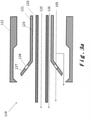
- FIG. 1 An example of a burner not in accordance with the invention is represented schematically according to an axial section on the picture 3a and in perspective on the figure 4a .
- the burner comprises a fuel conduit 120 surrounded by a cylindrical sleeve 121 comprising a flared portion 127 towards the end of the nose of the burner and comprising a plurality of holes 128.
- the cylindrical sleeve 121 forms with the conduit 120 an annular space through which passes a combustible gas 126.
- the sleeve 121 and the conduit 120 are included in an outer casing 122 (shown on the picture 3a , not shown on the figure 4a ) so that the nose of the conduit 120 protrudes from the flared portion 127 of the sleeve 121 and from the nose of the outer casing 122, that the flared portion 127 of the sleeve is recessed with respect to the nose of the outer casing 122.
- Axial primary air 105 can circulate between a space formed by the outer casing 122 and the sleeve 121, as well as by the plurality of holes 128 on the flared part of the sleeve.
- annular straight furnaces are small and short. They are sized for natural gas which burns instantaneously according to the “as soon as mixed, as soon as burned” law of homogeneous combustion (gas-gas combustion). In these chambers, too, the air required for combustion arrives premixed with recirculated flue gases, which have a reduced oxygen concentration.
- the object of the present invention is to remedy these drawbacks and therefore to propose a combustion method applicable in the combustion chambers of furnaces, in particular of existing furnaces, which is effective with a consumption of only pulverulent solid fuel.
- a combustion process has been provided as indicated at the beginning, in which the jet of solid fuel has an axial component of projection in the same direction as said direction of propagation of the combustion gas in the cylindrical combustion chamber and wherein the ratio of the specific momentum rate of the burner to the specific momentum rate of the combustion gas is equal to or less than 1.0 and greater than zero.
- the specific momentum rate is the measure of the force of a jet (eg burner jet or oxidant current) divided by the burner power.
- the basic principle in the design of burners is that a burner must have a significant and sufficient momentum flow rate (injection speed x mass flow rate) for the central fuel jet to be able to draw in the oxidizer arriving at its periphery, thereby forcing the fuel/oxidant mixture, which accelerates combustion.
- the aerodynamics of a flame of traditional design is therefore determined by the burner itself (see figure 1 ).
- the process according to the present invention is based on an aerodynamics which is determined by the oxidant arriving in the combustion chamber.
- the oxidizer here forces the fuel to enter its current by adapting the momentum rate of the burner to that of the oxidizer (see figure 2 ). It is therefore no longer the jet of fuel which is the driving force, it is the fuel which is driven by the oxidizer. This results in an increased residence time of the fuel, with the effect of making it possible to use a fuel only in a solid pulverulent form and to obtain total combustion of this fuel in the combustion chamber.
- this momentum flow rate of the burner it is possible, for example, to increase the fuel injection section in the nose of the burner, which has the immediate effect of reducing the fuel injection speed while maintaining unchanged the flow rates of fuel and oxidizer and the speed of the oxidizer and this has no influence on the operation of the furnace itself.
- This is a minor and easy modification to the burner nose, with immediate effect on the claimed ratio between specific momentum rates being adapted to become equal to or less than 1.0.
- this ratio will be between 0.5 and 0.9.
- the cylindrical combustion chamber has first and second axial ends and the jet of pulverulent solid fuel is projected by the burner from the first axial end of the combustion chamber towards the second axial end.
- the burner is arranged in a peephole provided in the front wall of the first end of the combustion chamber. The jet of solid fuel can thus come into contact with the oxidizer over the entire length of the combustion chamber.
- the combustion gas is mainly a flue gas recirculated, for example from the calcining furnace.
- This flue gas can be enriched with oxygen, for example by supplying air.
- the combustion gas is fed tangentially into the combustion chamber at said first end thereof, so as to form a helical current of combustion gas around the jet of fuel projected by the burner.
- This favors the fuel-oxidizer mixture.
- provision can also be made for the combustion gas to be fed into the combustion chamber at said first end of the latter, parallel to its axis and around the jet of fuel projected by the burner.
- the propagation of the combustion gas must in any case follow a direction of propagation towards the downstream end of the combustion chamber.
- the method according to the invention is intended to be preferably implemented in a lower combustion chamber of a straight annular kiln for calcining limestone or dolomitic rock.
- the present invention also relates to such a combustion chamber comprising, at a first axial end, a burner arranged to project a jet of pulverulent solid fuel into this chamber, and optionally an axial primary air flow, and a supply inlet for an oxidizing gas arranged so as to form a current of oxidizing gas in a direction of propagation around the jet of fuel projected by the burner, the burner being arranged to project the solid fuel in an axial component of projection having the same direction as the direction propagation of the current of oxidizing gas in the cylindrical combustion chamber, so as to allow the implementation of the method according to the invention.
- It also relates to a straight annular kiln for calcining limestone or dolomitic rock, comprising at least one such combustion chamber as well as a straight annular kiln for calcining limestone or dolomitic rock, implementing a process according to the invention.
- the specific momentum flow rate of the burner (transport air + coal) is much higher than that of the oxidizer.
- this combustion chamber 1 is illustrated schematically.
- the fuel is projected by the burner 2 at a very high injection speed 3 and the injection cone 4 formed by the fuel projected out of the nose of the burner has a very tapered shape. Thanks to this high injection speed, the oxidizer 5, fed around the jet of fuel, is sucked into it.
- a conventional annular straight furnace for calcining limestone or dolomitic rock comprises an outer cylinder 6 and an inner cylinder 7 forming an annular space 8 into which the material to be fired descends.
- the raw material is introduced from the top of the furnace at 9 and the cooked product is discharged from the bottom at 10.
- the fuel is injected at two levels, through several upper 11 and lower 12 combustion chambers (from 4 to 6 chambers depending on oven capacity). In general, 1/3 of the fuel is injected into chambers 11 and 2/3 into chambers 12. All of the fumes from the upper chambers 11 and part of the fumes from the lower chambers 12 are drawn upwards by a ventilation fan. draw 13, therefore against the current of the movement of the material load.
- this oxidizing gas 31 arrives at each of the chambers 12 tangentially to the axis of the chamber and therefore to the jet of the burner 18 injected axially. As a result, the combustion gas 31 acquires a rotational movement which induces a centrifugal force pushing the combustion gas 31 towards the walls of the cylindrical combustion chamber.
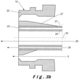
- the figure 3b shows an axial section of a burner embodiment according to the invention.
- the burner comprises a sleeve 21 comprising a central duct 20 through which the pulverulent solid fuel is fed.
- the sleeve 21 further comprises at least one additional conduit 23 through which combustible gas 26 can be supplied when the oven is switched on, and only then.
- An outer casing 22 envelops sleeve 21 and forms with it a space through which axial primary air 5 can be supplied to aid combustion.
- the outer casing 22 comprises a portion 19 whose internal diameter progressively reduces towards the nose of the burner, and the sleeve comprises a portion 27 whose external diameter gradually increases towards the nose of the burner so as to reduce the space between the nose of the outer casing 22 and the nose of the sleeve 21.
- This reduction in space between the outer casing 22 and the sleeve makes it possible to increase the injection speed of the axial primary air 5 into the combustion chamber without having to provide a high flow of axial primary air.
- the nose of the outer casing 22, the nose of the sleeve 21, the nose of the central conduit 20 and the nose of said at least one additional conduit 23 pass through a plane orthogonal to the axis 30 of the burner.
- the figure 4b shows a perspective view of a first embodiment of the burner according to the invention.
- the sleeve 21 comprises a central duct 20 through which the pulverulent solid fuel is fed.
- the sleeve 21 further comprises an additional duct 23 forming a thin annular space, through which combustible gas 26 can be supplied at the moment of ignition of the furnace, and only at that moment.
- An outer casing 22 (not shown in the figure 4b ) envelops sleeve 21 and forms a space through which axial primary air 5 can be supplied to aid combustion.
- the figure 4c shows a perspective view of another embodiment of the burner according to the invention.
- the sleeve 21 comprises a central duct 20 through which the pulverulent solid fuel is fed.
- the sleeve 21 further comprises a plurality of additional ducts 23 distributed around the central duct 20, these additional ducts 23 through which combustible gas 26 can be supplied when the oven is switched on, and only at this time.
- An outer casing 22 (not shown in the figure 4c ) envelops sleeve 21 and forms a space through which axial primary air 5 can be supplied to aid combustion.
- a reduction in the space between the sleeve 21 and the outer casing 22 can be achieved only by reducing the internal diameter of the casing 22 at the level of the nose of the burner and keeping the external diameter of the sleeve 21 constant, or alternatively by increasing the external diameter of the sleeve 21 at the level of the nose of the burner while keeping the internal diameter of the casing 22 constant.
- This reduction in space between the sleeve 21 and the casing makes it possible to provide a higher primary air injection speed at the outlet of the burner.
- the internal diameter of the envelope 22, the external diameter of the sleeve 21 and the space between the sleeve 21 and the external envelope remain constant.
- the axial primary air flow or the volume of the sleeve 21 or the volume of the interior of the casing 22 are adapted to allow the axial primary air to exit at a predefined speed at the nose of the burner.
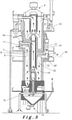
- the figure 5 shows a diagram of an annular furnace and includes a representation of one embodiment of a cylindrical combustion chamber 12 according to the invention.
- the combustion chamber comprises an inlet forming the casing 22 of the burner 18 and the axis 30 of the burner is preferably located in the axis 30' of the cylindrical combustion chamber 12.
- the combustion chamber 12 further comprises an oxidizing gas inlet 31 located tangentially with respect to the axis 30, 30' of the burner and of the cylindrical combustion chamber, as described above.
- the combustion gases are then evacuated from the combustion chamber through a conduit.
- the injection speed of the fuel transported by air is obtained by passing through the pipe 20 which has a section of 0.001 m 2 .
- the "force" of the burner i.e. its specific flow rate of momentum (axial primary air + transport air + coal) is still slightly greater than that of the oxidizer, but it is insufficient to suck the oxidizer into the fuel. It is not to be compared with that of the rotary kiln described above. And we therefore observe an unsatisfactory combustion with a furnace having the disadvantages described above.
- This arrangement allows a residence time of the particles increased drastically in the combustion chamber and therefore the oxygen is better available and the combustion is complete inside the combustion chamber.
Landscapes
- Engineering & Computer Science (AREA)
- Chemical & Material Sciences (AREA)
- Combustion & Propulsion (AREA)
- Mechanical Engineering (AREA)
- General Engineering & Computer Science (AREA)
- Pre-Mixing And Non-Premixing Gas Burner (AREA)
- Fluidized-Bed Combustion And Resonant Combustion (AREA)
- Muffle Furnaces And Rotary Kilns (AREA)
Claims (12)
- Verfahren zum Verbrennen von Brennstoff in einer zylindrischen Brennkammer (1), dieses umfasst in dieser Brennkammer,- eine Projektion, aus einem Brenner (2), für einen Pulverstrahl eines Festbrennstoffs (3), der durch eine Transportluft fortbewegt wird, und gegebenenfalls eines Primärluftstroms, und- eine Versorgung eines oxidierenden Gases (5) entlang einer Ausbreitungsrichtung, sodass eine Strömung aus oxidierendem Gas um den von dem Brenner ausgeworfenen Brennstoffstrahl herum gebildet wird, bei einer Temperatur, die eine Verbrennung des Brennstoffs verursacht,dadurch gekennzeichnet, dass der Strahl des Festbrennstoffs eine axiale Projektionskomponente in derselben Richtung wie die Ausbreitungsrichtung des oxidierenden Gases in der zylindrischen Brennkammer aufweist, und dadurch, dass das Verhältnis zwischen der spezifischen Impulsrate des Brenners und der spezifischen Impulsrate des oxidierenden Gases gleich oder kleiner als 1,0 und größer als null ist.
- Verfahren nach Anspruch 1, dadurch gekennzeichnet, dass das Verhältnis zwischen der spezifischen Impulsrate des Brenners und der spezifischen Impulsrate des oxidierenden Gases zwischen 0,25 und 0,9 liegt.
- Verfahren nach einem der Ansprüche 1 oder 2, dadurch gekennzeichnet, dass die zylindrische Brennkammer ein erstes und ein zweites axiales Ende aufweist und dadurch, dass der Strahl des pulverförmigen Festbrennstoffs durch den Brenner vom ersten axialen Ende der Brennkammer zum zweiten axialen Ende ausgeworfen wird.
- Verfahren nach Anspruch 3, dadurch gekennzeichnet, dass das oxidierende Gas tangential in die Brennkammer an deren erstem Ende zugeführt wird, sodass eine spiralförmige Strömung aus oxidierendem Gas um den vom Brenner ausgeworfenen Brennstoffstrahl gebildet wird.
- Verfahren nach Anspruch 3, dadurch gekennzeichnet, dass das oxidierende Gas in die Brennkammer an deren erstem Ende, parallel zu ihrer Achse und um den vom Brenner ausgeworfenen Brennstoffstrahl zugeführt wird.
- Verfahren nach einem der Ansprüche 1 bis 5, dadurch gekennzeichnet, dass es eine teilweise oder vollständige Drehung des von Transportluft getragenen Brennstoffstrahls umfasst.
- Verfahren nach einem der Ansprüche 1 bis 6, dadurch gekennzeichnet, dass es eine teilweise oder vollständige Drehung des Primärluftstroms umfasst.
- Verfahren nach einem der Ansprüche 1 bis 7, dadurch gekennzeichnet, dass das oxidierende Gas ein rezirkuliertes Rauchgas ist.
- Verfahren nach einem der Ansprüche 1 bis 8, dadurch gekennzeichnet, dass die Brennkammer eine der unteren Brennkammern eines Ringschachtofens für die Kalzinierung von Mineralgestein ist.
- Eine zylindrische Brennkammer (1), umfassend, an dem ersten axialen Ende, einen Brenner (2), der eingerichtet ist, um einen pulverförmigen Festbrennstoff (3) in diese Kammer auszuwerfen, und einen Einlass für ein oxidierendes Gas (5), der so angeordnet ist, dass eine Strömung aus oxidierendem Gas entlang einer Ausbreitungsrichtung um den vom Brenner ausgeworfenen Brennstoffstrahl gebildet wird, dadurch gekennzeichnet, dass der Brenner so angeordnet ist, das er den Festbrennstoff entlang einer axialen Projektionskomponente auswirft, die die gleiche Richtung hat, wie die Ausbreitungsrichtung des Gases in der zylindrischen Brennkammer, wobei diese Kammer eingerichtet und dimensioniert ist, um das Verfahren nach einem der Ansprüche 1 bis 9 umzusetzen.
- Ringschachtofen zur Kalzination von Mineralgestein, umfassend mindestens eine Brennkammer nach Anspruch 10.
- Durchführen eines Verfahrens nach einem der Ansprüche 1 bis 9 in einem Ringschachtofen zur Kalzination von Mineralgestein
Priority Applications (2)
| Application Number | Priority Date | Filing Date | Title |
|---|---|---|---|
| HRP20220707TT HRP20220707T1 (hr) | 2016-06-28 | 2017-06-28 | Postupak za izgaranje goriva u cilindričnoj komori za izgaranje |
| SI201731156T SI3475609T1 (sl) | 2016-06-28 | 2017-06-28 | Postopek za zgorevanje goriva v cilindrični zgorevalni komori |
Applications Claiming Priority (2)
| Application Number | Priority Date | Filing Date | Title |
|---|---|---|---|
| BE20165489A BE1023896B1 (fr) | 2016-06-28 | 2016-06-28 | Procede de combustion de combustible dans une chambre de combustion tubulaire |
| PCT/EP2017/066018 WO2018002151A1 (fr) | 2016-06-28 | 2017-06-28 | Procédé de combustion de combustible dans une chambre de combustion cylindrique |
Publications (2)
| Publication Number | Publication Date |
|---|---|
| EP3475609A1 EP3475609A1 (de) | 2019-05-01 |
| EP3475609B1 true EP3475609B1 (de) | 2022-03-09 |
Family
ID=56551093
Family Applications (1)
| Application Number | Title | Priority Date | Filing Date |
|---|---|---|---|
| EP17732472.0A Active EP3475609B1 (de) | 2016-06-28 | 2017-06-28 | Verfahren zum verbrennen von brennstoff in einer zylindrischen brennkammer |
Country Status (8)
| Country | Link |
|---|---|
| EP (1) | EP3475609B1 (de) |
| BE (2) | BE1023896B1 (de) |
| ES (1) | ES2915900T3 (de) |
| FR (1) | FR3053102B1 (de) |
| HR (1) | HRP20220707T1 (de) |
| PL (1) | PL3475609T3 (de) |
| SI (1) | SI3475609T1 (de) |
| WO (1) | WO2018002151A1 (de) |
Families Citing this family (2)
| Publication number | Priority date | Publication date | Assignee | Title |
|---|---|---|---|---|
| EP3805640A1 (de) | 2019-10-09 | 2021-04-14 | S.A. Lhoist Recherche Et Developpement | Brennkammer für einen ringförmigen vertikalen schachtofen und verfahren zur verbrennung in einer solchen brennkammer |
| BE1028191B9 (fr) | 2020-04-07 | 2021-11-30 | Lhoist Rech Et Developpement Sa | Procédé de calcination de chaux ou dolomie et four droit annulaire mis en œuvre |
Citations (3)
| Publication number | Priority date | Publication date | Assignee | Title |
|---|---|---|---|---|
| DE4102610A1 (de) | 1991-01-25 | 1992-07-30 | Ver Kraftwerks Ag Peitz Nieder | Kohlenstaub-drallbrenner |
| EP1033532A1 (de) | 1999-03-03 | 2000-09-06 | Hitachi, Ltd. | Feinkohlenstaubbrenner und Feinkohlenstaubverbrennungsvorrichtung |
| WO2010004009A2 (de) | 2008-07-11 | 2010-01-14 | Rheinkalk Gmbh | Brennereinheit und brenneranordnung für staubförmigen festbrennstoff |
Family Cites Families (2)
| Publication number | Priority date | Publication date | Assignee | Title |
|---|---|---|---|---|
| DE10232373B4 (de) * | 2002-07-17 | 2009-04-02 | Schoppe, Fritz, Dr.-Ing. | Verfahren zur Erhöhung der Flammstabilität bei Kohlenstaubfeuerungen und Vorrichtung zur Ausführung des Verfahrens |
| DE112004000319T5 (de) * | 2003-02-24 | 2006-02-02 | Posco, Pohang City | Brennervorrichtung zum Injizieren von pulverförmiger Kohle in drehbaren Brennöfen und zugehöriges Verfahren und zugehörige Vorrichtung zur Herstellung von CaO |
-
2016
- 2016-06-28 BE BE20165489A patent/BE1023896B1/fr active IP Right Grant
-
2017
- 2017-06-28 PL PL17732472.0T patent/PL3475609T3/pl unknown
- 2017-06-28 ES ES17732472T patent/ES2915900T3/es active Active
- 2017-06-28 WO PCT/EP2017/066018 patent/WO2018002151A1/fr unknown
- 2017-06-28 BE BE20175460A patent/BE1024784B9/fr active IP Right Grant
- 2017-06-28 SI SI201731156T patent/SI3475609T1/sl unknown
- 2017-06-28 EP EP17732472.0A patent/EP3475609B1/de active Active
- 2017-06-28 FR FR1755949A patent/FR3053102B1/fr active Active
- 2017-06-28 HR HRP20220707TT patent/HRP20220707T1/hr unknown
Patent Citations (3)
| Publication number | Priority date | Publication date | Assignee | Title |
|---|---|---|---|---|
| DE4102610A1 (de) | 1991-01-25 | 1992-07-30 | Ver Kraftwerks Ag Peitz Nieder | Kohlenstaub-drallbrenner |
| EP1033532A1 (de) | 1999-03-03 | 2000-09-06 | Hitachi, Ltd. | Feinkohlenstaubbrenner und Feinkohlenstaubverbrennungsvorrichtung |
| WO2010004009A2 (de) | 2008-07-11 | 2010-01-14 | Rheinkalk Gmbh | Brennereinheit und brenneranordnung für staubförmigen festbrennstoff |
Non-Patent Citations (4)
| Title |
|---|
| ABBAS; COSTEN T; LOCKWOOD P G; F C: "Solid Fuel Utilzation: From Coal to Biomass", TWENTY-SIXTH SYMPOSIUM (INTERNATIONAL) ON COMBUSTION/THE COMBUSTION INSTITUTE, vol. 26, no. 2, 1996, pages 3041 - 3058, XP022031905 |
| M.A. HASSAN ET AL.: "Influence of Different Firing Parameters on the Performance of a Pulverized Coal Furnace", SEVENTH ANNUAL INTERNATIONAL PITTSBURGH COAL CONFERENCE, 1990, pages 960 - 968, XP093011246 |
| T. LOCKWOOD: "Developments in oxyfuel combustion of coal", IES CLEAN COAL CENTRE, 2014, pages 1 - 122, XP093011252 |
| T. MATERN ET AL.: "Optimization of a Pulverized Brown Coal Burner", COMBUST. SCI. AND TECH., vol. 121, 1996, pages 255 - 269, XP093011245 |
Also Published As
| Publication number | Publication date |
|---|---|
| FR3053102A1 (fr) | 2017-12-29 |
| WO2018002151A1 (fr) | 2018-01-04 |
| BE1024784A1 (fr) | 2018-06-27 |
| BE1024784B9 (fr) | 2018-07-30 |
| BE1024784B1 (fr) | 2018-07-02 |
| FR3053102B1 (fr) | 2021-10-15 |
| BE1023896B1 (fr) | 2017-09-06 |
| BE1024784A9 (fr) | 2018-07-24 |
| HRP20220707T1 (hr) | 2022-07-22 |
| EP3475609A1 (de) | 2019-05-01 |
| PL3475609T3 (pl) | 2022-07-18 |
| SI3475609T1 (sl) | 2022-08-31 |
| ES2915900T3 (es) | 2022-06-27 |
Similar Documents
| Publication | Publication Date | Title |
|---|---|---|
| EP1907754B1 (de) | Verfahren und anlage für trägerlose magere kraftstoff-gas-verbrennung unter verwendung eines brenners und zugehöriger brenner | |
| EP0033285B1 (de) | Vorrichtung zum Mischen mit Turbulenz von Gas enthaltenden Fluida und festen Partikeln | |
| FR2485692A1 (fr) | Procede et bruleur pour produire une combustion a faible teneur en oxydes d'azote des gaz d'echappement dans un tube radiant | |
| FR2625295A1 (fr) | Procede et appareil destines a assurer la combustion etagee d'un melange combustible-comburant diminuant la production d'oxydes d'azote | |
| FR2535018A1 (fr) | Bruleur a charbon pulverise | |
| EP3475609B1 (de) | Verfahren zum verbrennen von brennstoff in einer zylindrischen brennkammer | |
| EP1031790B1 (de) | Verbesserungen an Flachflammenbrennern | |
| EP1913321B1 (de) | VERFAHREN ZUR KALZINIERUNG EINES MATERIALS MIT GERINGEN NOx-EMISSIONEN | |
| EP3724144B1 (de) | Klinkerproduktionsanlage und verfahren zur klinkerherstellung in einer solchen anlage | |
| FR2782780A1 (fr) | Procede de combustion pour bruler un combustible | |
| EP3058275A1 (de) | Schlanke gasbrenner | |
| EP1065461A1 (de) | In der Zementherstellung anwendbarer Verbrennungsprozess | |
| FR2795716A1 (fr) | Procede de calcination d'un materiau a base de minerai | |
| JP2008106221A (ja) | 炭化装置 | |
| FR2514864A1 (fr) | Tete de bruleur pour la combustion de combustibles solides | |
| EP2407716A1 (de) | Brenner für die Aufbereitung von brennbarem saurem Gas, und entsprechend angepasster Reaktionsofen und Prozess | |
| EP3903029B1 (de) | Brenner mit einstellbarer flamme | |
| CH655944A5 (fr) | Appareil pour la calcination du coke. | |
| FR2463360A1 (fr) | Installation de combustion a combustibles solides | |
| WO2009101361A2 (fr) | Procede de chauffage d'un cru mineral dans un four de cuisson de type four tunnel | |
| EP2314921A2 (de) | Verfahren zum Betrieb eines Heizkessels | |
| WO2014086660A1 (fr) | Brûleur | |
| FR2773388A1 (fr) | Procede et dispositif pour la combustion de combustible solide pulverise | |
| FR3006038A1 (fr) | Bruleur de four rotatif asymetrique | |
| BE652468A (de) |
Legal Events
| Date | Code | Title | Description |
|---|---|---|---|
| REG | Reference to a national code |
Ref country code: HR Ref legal event code: TUEP Ref document number: P20220707T Country of ref document: HR |
|
| STAA | Information on the status of an ep patent application or granted ep patent |
Free format text: STATUS: UNKNOWN |
|
| STAA | Information on the status of an ep patent application or granted ep patent |
Free format text: STATUS: THE INTERNATIONAL PUBLICATION HAS BEEN MADE |
|
| PUAI | Public reference made under article 153(3) epc to a published international application that has entered the european phase |
Free format text: ORIGINAL CODE: 0009012 |
|
| STAA | Information on the status of an ep patent application or granted ep patent |
Free format text: STATUS: REQUEST FOR EXAMINATION WAS MADE |
|
| STAA | Information on the status of an ep patent application or granted ep patent |
Free format text: STATUS: REQUEST FOR EXAMINATION WAS MADE |
|
| 17P | Request for examination filed |
Effective date: 20190122 |
|
| AK | Designated contracting states |
Kind code of ref document: A1 Designated state(s): AL AT BE BG CH CY CZ DE DK EE ES FI FR GB GR HR HU IE IS IT LI LT LU LV MC MK MT NL NO PL PT RO RS SE SI SK SM TR |
|
| AX | Request for extension of the european patent |
Extension state: BA ME |
|
| DAV | Request for validation of the european patent (deleted) | ||
| DAX | Request for extension of the european patent (deleted) | ||
| GRAP | Despatch of communication of intention to grant a patent |
Free format text: ORIGINAL CODE: EPIDOSNIGR1 |
|
| STAA | Information on the status of an ep patent application or granted ep patent |
Free format text: STATUS: GRANT OF PATENT IS INTENDED |
|
| INTG | Intention to grant announced |
Effective date: 20210927 |
|
| GRAS | Grant fee paid |
Free format text: ORIGINAL CODE: EPIDOSNIGR3 |
|
| GRAA | (expected) grant |
Free format text: ORIGINAL CODE: 0009210 |
|
| STAA | Information on the status of an ep patent application or granted ep patent |
Free format text: STATUS: THE PATENT HAS BEEN GRANTED |
|
| AK | Designated contracting states |
Kind code of ref document: B1 Designated state(s): AL AT BE BG CH CY CZ DE DK EE ES FI FR GB GR HR HU IE IS IT LI LT LU LV MC MK MT NL NO PL PT RO RS SE SI SK SM TR |
|
| REG | Reference to a national code |
Ref country code: CH Ref legal event code: EP Ref country code: AT Ref legal event code: REF Ref document number: 1474465 Country of ref document: AT Kind code of ref document: T Effective date: 20220315 |
|
| REG | Reference to a national code |
Ref country code: DE Ref legal event code: R096 Ref document number: 602017054336 Country of ref document: DE |
|
| REG | Reference to a national code |
Ref country code: IE Ref legal event code: FG4D Free format text: LANGUAGE OF EP DOCUMENT: FRENCH |
|
| REG | Reference to a national code |
Ref country code: RO Ref legal event code: EPE |
|
| REG | Reference to a national code |
Ref country code: LT Ref legal event code: MG9D Ref country code: ES Ref legal event code: FG2A Ref document number: 2915900 Country of ref document: ES Kind code of ref document: T3 Effective date: 20220627 |
|
| REG | Reference to a national code |
Ref country code: SE Ref legal event code: TRGR |
|
| REG | Reference to a national code |
Ref country code: HR Ref legal event code: ODRP Ref document number: P20220707T Country of ref document: HR Payment date: 20220615 Year of fee payment: 6 |
|
| REG | Reference to a national code |
Ref country code: NL Ref legal event code: MP Effective date: 20220309 |
|
| REG | Reference to a national code |
Ref country code: HR Ref legal event code: T1PR Ref document number: P20220707 Country of ref document: HR |
|
| PG25 | Lapsed in a contracting state [announced via postgrant information from national office to epo] |
Ref country code: RS Free format text: LAPSE BECAUSE OF FAILURE TO SUBMIT A TRANSLATION OF THE DESCRIPTION OR TO PAY THE FEE WITHIN THE PRESCRIBED TIME-LIMIT Effective date: 20220309 Ref country code: NO Free format text: LAPSE BECAUSE OF FAILURE TO SUBMIT A TRANSLATION OF THE DESCRIPTION OR TO PAY THE FEE WITHIN THE PRESCRIBED TIME-LIMIT Effective date: 20220609 Ref country code: LT Free format text: LAPSE BECAUSE OF FAILURE TO SUBMIT A TRANSLATION OF THE DESCRIPTION OR TO PAY THE FEE WITHIN THE PRESCRIBED TIME-LIMIT Effective date: 20220309 Ref country code: BG Free format text: LAPSE BECAUSE OF FAILURE TO SUBMIT A TRANSLATION OF THE DESCRIPTION OR TO PAY THE FEE WITHIN THE PRESCRIBED TIME-LIMIT Effective date: 20220609 |
|
| REG | Reference to a national code |
Ref country code: AT Ref legal event code: MK05 Ref document number: 1474465 Country of ref document: AT Kind code of ref document: T Effective date: 20220309 |
|
| REG | Reference to a national code |
Ref country code: GR Ref legal event code: EP Ref document number: 20220401154 Country of ref document: GR Effective date: 20220707 |
|
| PG25 | Lapsed in a contracting state [announced via postgrant information from national office to epo] |
Ref country code: LV Free format text: LAPSE BECAUSE OF FAILURE TO SUBMIT A TRANSLATION OF THE DESCRIPTION OR TO PAY THE FEE WITHIN THE PRESCRIBED TIME-LIMIT Effective date: 20220309 Ref country code: FI Free format text: LAPSE BECAUSE OF FAILURE TO SUBMIT A TRANSLATION OF THE DESCRIPTION OR TO PAY THE FEE WITHIN THE PRESCRIBED TIME-LIMIT Effective date: 20220309 |
|
| PG25 | Lapsed in a contracting state [announced via postgrant information from national office to epo] |
Ref country code: NL Free format text: LAPSE BECAUSE OF FAILURE TO SUBMIT A TRANSLATION OF THE DESCRIPTION OR TO PAY THE FEE WITHIN THE PRESCRIBED TIME-LIMIT Effective date: 20220309 |
|
| PG25 | Lapsed in a contracting state [announced via postgrant information from national office to epo] |
Ref country code: SM Free format text: LAPSE BECAUSE OF FAILURE TO SUBMIT A TRANSLATION OF THE DESCRIPTION OR TO PAY THE FEE WITHIN THE PRESCRIBED TIME-LIMIT Effective date: 20220309 Ref country code: PT Free format text: LAPSE BECAUSE OF FAILURE TO SUBMIT A TRANSLATION OF THE DESCRIPTION OR TO PAY THE FEE WITHIN THE PRESCRIBED TIME-LIMIT Effective date: 20220711 Ref country code: EE Free format text: LAPSE BECAUSE OF FAILURE TO SUBMIT A TRANSLATION OF THE DESCRIPTION OR TO PAY THE FEE WITHIN THE PRESCRIBED TIME-LIMIT Effective date: 20220309 Ref country code: AT Free format text: LAPSE BECAUSE OF FAILURE TO SUBMIT A TRANSLATION OF THE DESCRIPTION OR TO PAY THE FEE WITHIN THE PRESCRIBED TIME-LIMIT Effective date: 20220309 |
|
| PG25 | Lapsed in a contracting state [announced via postgrant information from national office to epo] |
Ref country code: IS Free format text: LAPSE BECAUSE OF FAILURE TO SUBMIT A TRANSLATION OF THE DESCRIPTION OR TO PAY THE FEE WITHIN THE PRESCRIBED TIME-LIMIT Effective date: 20220709 Ref country code: AL Free format text: LAPSE BECAUSE OF FAILURE TO SUBMIT A TRANSLATION OF THE DESCRIPTION OR TO PAY THE FEE WITHIN THE PRESCRIBED TIME-LIMIT Effective date: 20220309 |
|
| REG | Reference to a national code |
Ref country code: DE Ref legal event code: R026 Ref document number: 602017054336 Country of ref document: DE |
|
| PLBI | Opposition filed |
Free format text: ORIGINAL CODE: 0009260 |
|
| PLAB | Opposition data, opponent's data or that of the opponent's representative modified |
Free format text: ORIGINAL CODE: 0009299OPPO |
|
| PLAX | Notice of opposition and request to file observation + time limit sent |
Free format text: ORIGINAL CODE: EPIDOSNOBS2 |
|
| 26 | Opposition filed |
Opponent name: FELS VERTRIEBS- UND SERVICE GMBH & CO. KG Effective date: 20221208 |
|
| R26 | Opposition filed (corrected) |
Opponent name: FELS VERTRIEBS- UND SERVICE GMBH & CO. KG Effective date: 20221208 |
|
| PG25 | Lapsed in a contracting state [announced via postgrant information from national office to epo] |
Ref country code: MC Free format text: LAPSE BECAUSE OF FAILURE TO SUBMIT A TRANSLATION OF THE DESCRIPTION OR TO PAY THE FEE WITHIN THE PRESCRIBED TIME-LIMIT Effective date: 20220309 Ref country code: DK Free format text: LAPSE BECAUSE OF FAILURE TO SUBMIT A TRANSLATION OF THE DESCRIPTION OR TO PAY THE FEE WITHIN THE PRESCRIBED TIME-LIMIT Effective date: 20220309 |
|
| GBPC | Gb: european patent ceased through non-payment of renewal fee |
Effective date: 20220628 |
|
| PLBB | Reply of patent proprietor to notice(s) of opposition received |
Free format text: ORIGINAL CODE: EPIDOSNOBS3 |
|
| PG25 | Lapsed in a contracting state [announced via postgrant information from national office to epo] |
Ref country code: GB Free format text: LAPSE BECAUSE OF NON-PAYMENT OF DUE FEES Effective date: 20220628 |
|
| P01 | Opt-out of the competence of the unified patent court (upc) registered |
Effective date: 20230526 |
|
| REG | Reference to a national code |
Ref country code: HR Ref legal event code: ODRP Ref document number: P20220707 Country of ref document: HR Payment date: 20230608 Year of fee payment: 7 |
|
| PGFP | Annual fee paid to national office [announced via postgrant information from national office to epo] |
Ref country code: RO Payment date: 20230612 Year of fee payment: 7 Ref country code: IE Payment date: 20230619 Year of fee payment: 7 Ref country code: FR Payment date: 20230515 Year of fee payment: 7 Ref country code: DE Payment date: 20230627 Year of fee payment: 7 Ref country code: CZ Payment date: 20230628 Year of fee payment: 7 |
|
| PGFP | Annual fee paid to national office [announced via postgrant information from national office to epo] |
Ref country code: TR Payment date: 20230608 Year of fee payment: 7 Ref country code: SK Payment date: 20230612 Year of fee payment: 7 Ref country code: SI Payment date: 20230607 Year of fee payment: 7 Ref country code: SE Payment date: 20230626 Year of fee payment: 7 Ref country code: PL Payment date: 20230607 Year of fee payment: 7 Ref country code: LU Payment date: 20230626 Year of fee payment: 7 Ref country code: HR Payment date: 20230608 Year of fee payment: 7 Ref country code: GR Payment date: 20230620 Year of fee payment: 7 |
|
| PGFP | Annual fee paid to national office [announced via postgrant information from national office to epo] |
Ref country code: BE Payment date: 20230515 Year of fee payment: 7 |
|
| PGFP | Annual fee paid to national office [announced via postgrant information from national office to epo] |
Ref country code: IT Payment date: 20230620 Year of fee payment: 7 Ref country code: ES Payment date: 20230721 Year of fee payment: 7 Ref country code: CH Payment date: 20230702 Year of fee payment: 7 |
|
| PG25 | Lapsed in a contracting state [announced via postgrant information from national office to epo] |
Ref country code: HU Free format text: LAPSE BECAUSE OF FAILURE TO SUBMIT A TRANSLATION OF THE DESCRIPTION OR TO PAY THE FEE WITHIN THE PRESCRIBED TIME-LIMIT; INVALID AB INITIO Effective date: 20170628 |
|
| PG25 | Lapsed in a contracting state [announced via postgrant information from national office to epo] |
Ref country code: MK Free format text: LAPSE BECAUSE OF FAILURE TO SUBMIT A TRANSLATION OF THE DESCRIPTION OR TO PAY THE FEE WITHIN THE PRESCRIBED TIME-LIMIT Effective date: 20220309 Ref country code: CY Free format text: LAPSE BECAUSE OF FAILURE TO SUBMIT A TRANSLATION OF THE DESCRIPTION OR TO PAY THE FEE WITHIN THE PRESCRIBED TIME-LIMIT Effective date: 20220309 |