EP3474995B1 - Dispositif de broyage à haut débit comportant une opération de broyage réglable - Google Patents
Dispositif de broyage à haut débit comportant une opération de broyage réglable Download PDFInfo
- Publication number
- EP3474995B1 EP3474995B1 EP17737057.4A EP17737057A EP3474995B1 EP 3474995 B1 EP3474995 B1 EP 3474995B1 EP 17737057 A EP17737057 A EP 17737057A EP 3474995 B1 EP3474995 B1 EP 3474995B1
- Authority
- EP
- European Patent Office
- Prior art keywords
- grinding
- rotor
- screen
- axis
- drive unit
- Prior art date
- Legal status (The legal status is an assumption and is not a legal conclusion. Google has not performed a legal analysis and makes no representation as to the accuracy of the status listed.)
- Active
Links
Images


Classifications
-
- B—PERFORMING OPERATIONS; TRANSPORTING
- B02—CRUSHING, PULVERISING, OR DISINTEGRATING; PREPARATORY TREATMENT OF GRAIN FOR MILLING
- B02C—CRUSHING, PULVERISING, OR DISINTEGRATING IN GENERAL; MILLING GRAIN
- B02C4/00—Crushing or disintegrating by roller mills
- B02C4/10—Crushing or disintegrating by roller mills with a roller co-operating with a stationary member
- B02C4/26—Crushing or disintegrating by roller mills with a roller co-operating with a stationary member in the form of a grid or grating
-
- B—PERFORMING OPERATIONS; TRANSPORTING
- B02—CRUSHING, PULVERISING, OR DISINTEGRATING; PREPARATORY TREATMENT OF GRAIN FOR MILLING
- B02C—CRUSHING, PULVERISING, OR DISINTEGRATING IN GENERAL; MILLING GRAIN
- B02C18/00—Disintegrating by knives or other cutting or tearing members which chop material into fragments
- B02C18/06—Disintegrating by knives or other cutting or tearing members which chop material into fragments with rotating knives
- B02C18/16—Details
- B02C18/24—Drives
-
- B—PERFORMING OPERATIONS; TRANSPORTING
- B02—CRUSHING, PULVERISING, OR DISINTEGRATING; PREPARATORY TREATMENT OF GRAIN FOR MILLING
- B02C—CRUSHING, PULVERISING, OR DISINTEGRATING IN GENERAL; MILLING GRAIN
- B02C13/00—Disintegrating by mills having rotary beater elements ; Hammer mills
- B02C13/14—Disintegrating by mills having rotary beater elements ; Hammer mills with vertical rotor shaft, e.g. combined with sifting devices
-
- B—PERFORMING OPERATIONS; TRANSPORTING
- B02—CRUSHING, PULVERISING, OR DISINTEGRATING; PREPARATORY TREATMENT OF GRAIN FOR MILLING
- B02C—CRUSHING, PULVERISING, OR DISINTEGRATING IN GENERAL; MILLING GRAIN
- B02C18/00—Disintegrating by knives or other cutting or tearing members which chop material into fragments
- B02C18/06—Disintegrating by knives or other cutting or tearing members which chop material into fragments with rotating knives
- B02C18/062—Disintegrating by knives or other cutting or tearing members which chop material into fragments with rotating knives with rotor elements extending axially in close radial proximity of a concentrically arranged slotted or perforated ring
-
- B—PERFORMING OPERATIONS; TRANSPORTING
- B02—CRUSHING, PULVERISING, OR DISINTEGRATING; PREPARATORY TREATMENT OF GRAIN FOR MILLING
- B02C—CRUSHING, PULVERISING, OR DISINTEGRATING IN GENERAL; MILLING GRAIN
- B02C18/00—Disintegrating by knives or other cutting or tearing members which chop material into fragments
- B02C18/06—Disintegrating by knives or other cutting or tearing members which chop material into fragments with rotating knives
- B02C18/16—Details
- B02C18/18—Knives; Mountings thereof
- B02C18/186—Axially elongated knives
-
- E—FIXED CONSTRUCTIONS
- E04—BUILDING
- E04F—FINISHING WORK ON BUILDINGS, e.g. STAIRS, FLOORS
- E04F11/00—Stairways, ramps, or like structures; Balustrades; Handrails
- E04F11/18—Balustrades; Handrails
- E04F11/1863—Built-in aids for ascending or descending stairs
Definitions
- the present invention relates to a grinding device capable of implementing a grinding operation which makes it possible to adjust the grinding parameters and which allows a high throughput of the ground material.
- the material to be ground is ground between a rotary rotor and a screen.
- the desired properties of the crushed material can be obtained by suitably selecting the appropriate crushing parameters, such as the rotational speed of the rotor and / or the oscillation amplitude and frequency in the case where the rotor is oscillating.
- the correct selection of the appropriate grinding parameters is also critical to avoid a significant increase in temperature which could be detrimental to the quality of the ground material.
- the grinding device of the invention makes it possible to implement a grinding operation in which it is possible to adjust the grinding parameters, while allowing a high flow rate of the ground material.
- the figure 1 shows a grinding device 1 for implementing a grinding operation, according to one embodiment.
- the grinding unit 2 comprises a body 3 comprising a grinding chamber 20.
- a rotor 4 is rotatably mounted around an axis 5 in the body 3.
- a screen 21 is mounted concentrically around the rotor 4.
- a drive unit 60 (only partially visible in the figure 1 ) can be functionally connected to the grinding unit 2 in order to drive the rotor 4 relative to the screen 21 during the grinding operation.
- the rotor 4 is mounted substantially vertically, concentric with the screen 21.
- the material to be ground can be introduced into the grinding chamber 20 from above, through an inlet 32. During the grinding operation, the material is ground by the combined action of the rotor 4 and the screen 21 and the ground material which has passed through the screen 21 exits from the grinding unit 2 through an outlet 33 (from below).
- the grinding device 1 comprises a transmission element 61 comprising a grinding shaft 6 on which the rotor 4 is mounted.
- the transmission element 61 is configured to transmit the drive from the drive unit 60 to the shaft grinding 6.
- the transmission element 61 comprises a transmission joint 62 allowing the driving of the grinding shaft 6 by means of a transmission shaft 63, substantially orthogonal to the grinding shaft 6.
- the grinding shaft 6 is mounted in a grinding shaft bearing 64 and the transmission shaft 63 is mounted in a transmission bearing 65.
- the transmission element 61 can also be configured so as to drive the rotor 4 directly from above or from below, that is to say, provide a functional connection according to the orientation of the axis 5 of rotation of the rotor 4 (direct transmission).
- the transmission element 61 also comprises a connection unit 30 making it possible to functionally connect the grinding unit 2 to the drive unit 60, via the transmission element 61.
- the connection unit 30 is configured to allow the transmission element 61 to be connected to the drive unit 60 in a removable manner.
- the connection of the transmission element 61 to the drive unit 60 may comprise a collar of the "Tri-clamp" type or any other suitable quick connection system.
- the drive unit 60 drives the drive shaft. grinding 6 in rotation about the axis 5.
- the movements of the rotor 4 relative to the screen 21 can be controlled so as to carry out the grinding operation, that is to say, allow the fractionation of the material to be ground by the combined action of the rotor 4 and the screen 21, according to the desired grinding specifications.
- the grinding chamber 2 configured so that the material circulates from top to bottom (between the inlet 32 and the outlet 33), in a direction substantially parallel to the axis 5 of rotation of the rotor 4, makes it possible to take advantage of gravity and to increase the flow rate of the ground material compared to a device in which the rotor and the screen are oriented horizontally.
- the flow rate of the ground material is also increased by the larger surface of the concentric screen 21 with respect to a screen placed under a rotor rotating along an axis oriented horizontally.
- connection unit 30 includes an adapter module 31 configured to adapt the characteristics of the drive unit 60 to the needs of the grinding unit 2 functionally connected to the drive unit 60. It is thus possible to connect different grinding units 2 functionally depending on the grinding process which it is desired to carry out.
- An advantage of the connection unit 30 is that a single drive unit 60 can be used for several grinding chambers 2, reducing the costs of the equipment.
- the flow rate of the material to be ground entering the grinding chamber 2 can be regulated by the addition of a metering system (not shown).
- the flow rate can also be modified by entraining the material in an air flow (not shown).
- a protective air flow 50 can be injected along the rotor shaft 5, directed towards the rotor 4 so as to prevent infiltration of the material to be ground in the transmission element 61 and to avoid a risk overheating of the transmission element 61 and of the rotor 4.
- the drive unit 60 and / or the transmission element 61 can integrate a cooling system to allow treatment of thermally sensitive materials.
- the grinding device 1 can be adapted for cryogenic grinding or vacuum grinding.
- the grinding device 1 can be used under an inert atmosphere to allow the treatment of explosive products.
- the figure 2 shows a perspective view of the screen 21, according to one embodiment.
- the screen 21 is cylindrical and can be mounted in the body 3 of the grinding chamber 2 concentric with the axis 5 of rotation of the rotor 4.
- the screen 21 is mounted between two support rings 22 held together by screws 23.
- the lower support ring 22 comprises a screen bearing 24 for mounting the screen 21 on the grinding shaft bearing 64.
- the screen 21 may consist of a filtering part 25 and a support part 26.
- the support part 26 is provided with large openings 27 through which the ground material passes through the filtering part 25 during the grinding operation. .
- the support part 26 may consist of a thick and solid element, ensuring the screen 21 a certain rigidity.
- the filtering part 25 can be composed of fine openings in order to facilitate a fluid flow of material flow.
- the screen 21 can be made of a metal alloy material.
- the filtering portion 25 and the support portion 26 are formed integrally so that the screen 21 is formed in one piece.
- Such a sieve 21 makes it possible, in contrast to sieves made up of several glued or welded elements, to prevent powdery materials from interfering in cavities, between the filtering portion 25 and the support portion 26.
- the cylindrical sieve 21 allows more large grinding surface.
- the screen 21 can be coupled to a vibration generator (not shown) so as to facilitate the flow of the ground material through the screen 21.
- the effect of the vibration makes it possible to prevent the material from coming together in the openings of the screen 21 during the grinding operation, thus allowing a continuous flow of the ground material, without human intervention.
- the vibrations generated by the vibration generator are transmitted to the filter part 25 of the screen 21 very efficiently. This results in an acceleration of the circulation of the ground material, in particular making it possible to avoid the risks of stagnation of the powdery materials.
- the screen 21 formed in one piece is advantageous since the latter is devoid of bonding or welding zones and is not likely to be weakened by the vibrations exerted by the vibration generator.
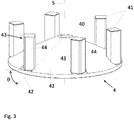
- the rotor 4 comprises a bearing 40 arranged to be mounted on a grinding shaft 6 parallel to the axis 5.
- a plurality of blades 41 are arranged concentric with the axis 5 of rotation of the rotor 4 and substantially parallel to this axis 5.
- the rotor 4 comprises a disc 42 extending radially from the bearing 40.
- the blades are mounted at the periphery of the disc 42.
- the rotor comprises five blades 41 distributed angularly equidistant.
- a different number of blades 41 as well as a different arrangement are also possible depending on the needs of the grinding process.
- the disc 42 occupies substantially the entire surface under the screen 21 so as to direct the material to be ground on the sides, that is to say by passing through the screen 21.
- the disc 42 has a frustoconical shape so that the material to be ground is guided towards the grinding zone, that is to say towards the blades 41 and the screen 21.
- the frustoconical shape of the disc 42 prevents the material to be ground to reside for too long (in other words, avoids a zone for retaining the material to be ground) in the region between the rotor bearing 40 and the blades 41.
- the movement of the rotor 4 relative to the screen 21 comprises a rotary movement around the axis 5.
- the speed of rotation of the rotor 4 can be varied, for example, depending on the grinding process, the type rotor 4 and / or sieve 21 and the material to be ground.
- the speed of rotation of the rotor 4 can also be varied during the grinding process.
- the movement of the rotor 4 relative to the screen 21 also includes an oscillation movement with an oscillation frequency which can be varied during the grinding operation.
- the rotor 4 can be pivoted in one direction or the other relative to the screen 21.
- the oscillation movement can be done with a predetermined oscillation angle (that is to say with an amplitude d 'predetermined oscillation).
- the predetermined oscillation angle can have a value between 0 and 360 °.
- the predetermined oscillation angle can also correspond to several complete turns in the same direction.
- the rotor can oscillate with an oscillation frequency between 0 and 4 Hz.
- the oscillation frequency can be varied during the grinding operation.
- a vibratory movement of the rotor 4 can be obtained when the latter is oscillated with an oscillation frequency less than about 2 °.
- the movement of the rotor 4 with respect to the screen 21 may also include a shift of the oscillation angle during the grinding operation, for example each time the swing movement of the rotor 4 oscillates.
- a shift of the angle oscillation means that the angular position of the rotor 4 is offset by the oscillation angle offset value after the completion of an oscillation cycle (an oscillation movement).
- the offset of the oscillation angle can be between 0 and 90 °.
- the offset of the oscillation angle can be varied during the grinding operation.
- the drive unit 60 may comprise a controller configured so as to determine grinding parameters on the basis of signals supplied by a sensor. The parameters determined by the controller can then be used to control the drive unit 60 so as to drive the rotor 4 according to the determined parameters.
- the grinding operation can be optimized as a function of the material to be ground and of the grinding conditions, which are measured by the sensor. The movements of the rotor 4 can therefore be controlled in real time during the grinding operation.
- the movements of the rotor 4 relative to the screen 21 described above can be adjusted according to the grinding parameters determined by the controller on the basis of the signals supplied by the sensor.
- the blades 41 are illustrated with a substantially square section. However, other blade configurations 41 are also possible depending on the grinding process or processes which it is desired to carry out.
- a first longitudinal face 43 of the blade 41 has a profile which differs from a second longitudinal face 44 opposite the first face 43.
- the 'one of the first or second face 43, 44 corresponds to the leading edge, that is to say the side of the blade 41 which faces the material during the rotation of the rotor 4.
- the other face 44, 43 corresponds to the leading edge. In this way, it is possible to carry out two different grinding processes according to the direction of rotation of the rotor 4.
- the blades 41 are configured so as to exert a thrust towards the screen 21 of the material.
- This type of configuration of the blades 41 is particularly suitable when the rotor rotates at low speed, for example, when the speed of the rotor 4 is between 0 and 200 rpm.
- An example of such a configuration is shown in figure 3 , in which the blades 41 of substantially square section are arranged with the faces 43, 44 making an angle ⁇ with respect to a radius 45 of the rotor 4.
- Such a configuration of the blades 41 has the effect that the ground material is pushed towards the screen 21 due to the inclination of the faces 43, 44 relative to the screen 21.
- the angle ⁇ can vary between 10 ° and 80 °, but is preferably between 40 ° and 60 °.
- the blades can be arranged with one of the faces substantially parallel to the sieve 21, that is to say, with an angle ⁇ substantially zero or any other angle ⁇ between 0 ° and 10 ° and between 80 ° and 90 °.
- the speed of the rotor 4 can also be greater than 200 rpm.
Landscapes
- Engineering & Computer Science (AREA)
- Food Science & Technology (AREA)
- Architecture (AREA)
- Civil Engineering (AREA)
- Structural Engineering (AREA)
- Crushing And Grinding (AREA)
- Crushing And Pulverization Processes (AREA)
Description
- La présente invention concerne un dispositif de broyage pouvant mettre en oeuvre une opération de broyage qui permet d'ajuster les paramètres de broyage et qui permet un débit élevé de la matière broyée.
- Dans les broyeurs oscillants classiques, le matériau à broyer est broyé entre un rotor rotatif et un tamis. Les propriétés souhaitées du matériau broyé, comme la taille des grains de particules et la vitesse d'écoulement des particules, peuvent être obtenues en sélectionnant de manière adéquate les paramètres de broyage appropriés, tels que la vitesse de rotation du rotor et/ou l'amplitude d'oscillation et de la fréquence dans le cas où le rotor est oscillant. La sélection correcte des paramètres de broyage appropriés est également critique pour éviter une augmentation importante de la température qui pourrait être préjudiciable à la qualité de la matière broyée. Au cours de la plupart des opérations de broyage, cependant, il peut être difficile de choisir les paramètres qui sont appropriés pendant toute l'opération de broyage. En effet, lors du broyage, le matériau peut modifier ses propriétés, par exemple en raison de la température et/ou humidité élevée, ce qui rend les paramètres de broyage insuffisants. Pour obtenir une taille de particule acceptable et uniforme du matériau broyé, il est nécessaire de modifier les paramètres de broyage pendant l'opération de broyage. Un autre problème est d'obtenir un débit élevé de la matière broyée. Le document
US2013/119172A1 décrit un dispositif de broyage qui comprend un rotor monté rotatif et un ensemble tamis, et il divulgue le préambule de la revendication 1. - La présente invention concerne un dispositif de broyage pour mettre en oeuvre une opération de broyage, comprenant:
- une unité de broyage incluant un corps qui comporte une chambre de broyage, laquelle peut être remplie d'une matière à broyer, un rotor monté rotatif autour d'un axe dans le corps, un tamis , et une unité d'entrainement commandant les mouvements de le rotor par rapport au tamis pendant l'opération de broyage;
- dans lequel l'unité d'entrainement est conçue pour fournir un mouvement d'oscillation au rotor autour de l'axe, l'angle d'oscillation pouvant être varié pendant l'opération de broyage; et
- dans lequel la chambre de broyage est configurée de manière à diriger le produit à broyer selon une direction sensiblement parallèle à l'axe de rotation du rotor; caractérisé en ce que le dispositif comporte un élément de transmission comprenant un arbre de broyage sur lequel est monté le rotor, l'élément de transmission transmettant l'entraînement de l'unité d'entraînement à l'arbre de broyage; le rotor étant monté verticalement, concentrique avec le tamis; et en ce que le rotor comporte un palier arrangé pour être monté sur un arbre de broyage et un disque s'étendant radialement à partir du palier, le disque étant de forme tronconique, de sorte à guider la matière à broyer vers les lames et le tamis.
- Le dispositif de broyage de l'invention permet de mettre en oeuvre une opération de broyage dans laquelle il est possible d'ajuster les paramètre de broyage, tout en permettant un débit élevé de la matière broyée.
- Des exemples de mise en oeuvre de l'invention sont indiqués dans la description illustrée par les figures annexées dans lesquelles :
- la
figure 1 montre un dispositif 1 de broyage comportant un rotor et un tamis, selon un mode de réalisation; - la
figure 2 montre une vue en perspective du tamis; et - la
figure 3 montre une vue détaillée du rotor, selon un mode de réalisation. - La
figure 1 montre un dispositif 1 de broyage pour mettre en oeuvre une opération de broyage, selon un mode de réalisation. L'unité de broyage 2 comprend un corps 3 comportant une chambre 20 de broyage. Un rotor 4 est monté rotatif autour d'un axe 5 dans le corps 3. Un tamis 21 est monté concentrique autour du rotor 4. Une unité d'entrainement 60 (seulement partiellement visible dans lafigure 1 ) peut être fonctionnellement connectée à l'unité de broyage 2 afin d'entraîner le rotor 4 par rapport au tamis 21 pendant l'opération de broyage. Selon cet arrangement, le rotor 4 est monté sensiblement verticalement, concentrique avec le tamis 21. - La matière à broyer peut être introduite dans la chambre 20 de broyage du dessus, par une entrée 32. Lors de l'opération de broyage, la matière est broyée par l'action combinée du rotor 4 et du tamis 21 et la matière broyé qui a traversé le tamis 21 sort de l'unité de broyage 2 par une sortie 33 (par le bas).
- Le dispositif 1 de broyage comporte un élément de transmission 61 comprenant un arbre de broyage 6 sur lequel est monté le rotor 4. L'élément de transmission 61 est configuré pour transmettre l'entraînement de l'unité d'entraînement 60 à l'arbre de broyage 6.
- Selon une forme préférée, l'élément de transmission 61 comprend un joint de transmission 62 permettant l'entraînement de l'arbre de broyage 6 par l'intermédiaire d'un arbre de transmission 63, sensiblement orthogonal à l'arbre de broyage 6. L'arbre de broyage 6 est monté dans un palier d'arbre de broyage 64 et l'arbre de transmission 63 est monté dans un palier de transmission 65.
- L'élément de transmission 61 peut également être configuré de manière à entraîner le rotor 4 directement par le haut ou par le bas, c'est-à-dire, fournir une connexion fonctionnelle selon l'orientation de l'axe 5 de rotation du rotor 4 (transmission directe).
- Avantageusement, l'élément de transmission 61 comporte également une unité de connexion 30 permettant de connecter de manière fonctionnelle l'unité de broyage 2 à l'unité d'entraînement 60, par l'intermédiaire de l'élément de transmission 61. L'unité de connexion 30 est configurée pour permettre de connecter l'élément de transmission 61 à l'unité d'entraînement 60 de manière amovible. La connexion de l'élément de transmission 61 à l'unité d'entraînement 60 peut comprendre un collier de type "Tri-clamp" ou tout autre système de connexion rapide approprié.
- Lorsque l'unité de broyage 2 est connecté à l'unité d'entraînement 60, par l'intermédiaire de l'élément de transmission 61 et de l'unité de connexion 30, l'unité d'entraînement 60 entraîne l'arbre de broyage 6 en rotation autour de l'axe 5. Les mouvements du rotor 4 par rapport au tamis 21 peuvent être commandés de sorte à réaliser l'opération de broyage, c'est-à-dire, permettre le fractionnement de la matière à broyer par l'action combinée du rotor 4 et du tamis 21, selon les spécifications de broyage désirées.
- La chambre de broyage 2 configurée de manière à ce que la matière circule de haut en bas (entre l'entrée 32 et la sortie 33), selon une direction sensiblement parallèle à l'axe 5 de rotation du rotor 4, permet de profiter de la gravité et d'augmenter le débit de la matière broyée par rapport à un dispositif dans lequel le rotor et le tamis sont orientés horizontalement. Le débit de la matière broyée est également augmenté par la surface plus grande du tamis 21 concentrique par rapport à un tamis placé sous un rotor tournant selon un axe orienté horizontalement.
- Dans un mode de réalisation, l'unité de connexion 30 inclut un module adaptateur 31 configuré pour adapter les caractéristiques de l'unité d'entraînement 60 aux besoins de l'unité de broyage 2 fonctionnellement connectée à l'unité d'entraînement 60. Il est ainsi possible de connecter de manière fonctionnelle différentes unités de broyage 2 en fonction du procédé de broyage que l'on souhaite exécuter. Un avantage de l'unité de connexion 30 est qu'une seule unité d'entraînement 60 peut être utilisée pour plusieurs chambres de broyage 2, diminuant les coûts de l'équipement.
- Le débit de la matière à broyer entrant dans la chambre 2 de broyage peut être régulé par l'ajout d'un système de dosage (non représenté). Le débit peut également être modifié par entraînement de la matière dans un flux d'air (non représenté).
- Un flux d'air de protection 50 peut être injecté le long de l'arbre 5 de rotor, dirigé vers le rotor 4 de manière à empêcher une infiltration de la matière à broyer dans l'élément de transmission 61 et d'éviter un risque de surchauffe de l'élément de transmission 61 et du rotor 4.
- L'unité d'entraînement 60 et/ou l'élément de transmission 61 peuvent intégrer un système de refroidissement pour permettre de traiter des matières sensibles thermiquement.
- Le dispositif 1 de broyage peut être adapté pour du broyage cryogénique ou du broyage sous vide. Le dispositif 1 de broyage peut être utilisé sous atmosphère inerte pour permettre de traiter des produits explosifs.
- La
figure 2 montre une vue en perspective du tamis 21, selon un mode de réalisation. Le tamis 21 est cylindrique et peut être monté dans le corps 3 de la chambre de broyage 2 de manière concentrique à l'axe 5 de rotation du rotor 4. Dans l'exemple illustré, le tamis 21 est monté entre deux anneaux de support 22 maintenus solidaires par des vis 23. L'anneau de support 22 inférieur comprend un palier de tamis 24 pour le montage du tamis 21 sur le palier d'arbre de broyage 64. - Le tamis 21 peut être constitué d'une partie filtrante 25 et d'une partie support 26. La partie support 26 est pourvue de larges ouvertures 27 par lesquelles la matière broyée passe au travers de la partie filtrante 25 lors de l'opération de broyage. La partie support 26 peut être constituée d'un élément épais et solide, assurant au tamis 21 une certaine rigidité. La partie filtrante 25 peut être composée de fines ouvertures afin de faciliter un débit fluide d'écoulement des matières. Le tamis 21 peut être fabriqué dans un matériau en alliage métallique. De façon préférée, la partie filtrante 25 et la partie support 26 sont formées intégralement de sorte que le tamis 21 est formé d'une seule pièce. Un tel tamis 21 permet, par opposition aux tamis constitués de plusieurs éléments collés ou soudés, d'éviter que les matières poudreuses s'immiscent dans des cavités, entre la partie filtrante 25 et la partie support 26. Le tamis 21 cylindrique permet une plus grande surface de broyage.
- Le tamis 21 peut être couplé à un générateur de vibrations (non représenté) de manière à faciliter l'écoulement de la matière broyée au travers du tamis 21. L'effet de la vibration permet d'éviter que la matière vienne s'agglomérer dans les ouvertures du tamis 21 pendant l'opération de broyage, permettant ainsi un flux continu de la matière broyée, sans intervention humaine. En effet, les vibrations engendrées par le générateur de vibrations sont transmises à la partie filtrante 25 du tamis 21 de manière très efficace. Cela entraine une accélération de la circulation de la matière broyée, en permettant notamment d'éviter les risques de stagnation des matières poudreuses. Dans ce cas, le tamis 21 formé d'une seule pièce est avantageux puisque ce dernier est dépourvu de zones de collage ou de soudure et ne risque pas d'être fragilisé par les vibrations exercées par le générateur de vibrations.
- Une vue détaillée du rotor 4 est montrée à la
figure 3 , selon un mode de réalisation. Le rotor 4 comporte un palier 40 arrangé pour être monté sur un arbre de broyage 6 parallèle à l'axe 5. Une pluralité de lames 41 sont disposées concentriques avec l'axe 5 de rotation du rotor 4 et sensiblement parallèle à cet axe 5. Le rotor 4 comprend un disque 42 s'étendant radialement à partir du palier 40. Les lames sont montées à la périphérie du disque 42. Dans l'exemple illustré, le rotor comporte cinq lames 41 distribuée angulairement équidistantes. Cependant un nombre différent de lames 41 ainsi qu'une disposition différente sont également possibles selon les besoin du procédé de broyage. - De manière préférée, le disque 42 occupe sensiblement toute la surface sous le tamis 21 de sorte à diriger la matière à broyer sur les côtés, c'est-à-dire en passant au travers du tamis 21.
- Avantageusement, le disque 42 a une forme tronconique de manière à ce que la matière à broyer est guidée vers la zone de broyage, c'est-à-dire vers les lames 41 et le tamis 21. De la sorte, la forme tronconique du disque 42 évite que la matière à broyer réside trop longtemps (autrement dit, évite une zone de rétention de la matière à broyer) dans la région comprise entre le palier de rotor 40 et les lames 41.
- Dans un mode de réalisation, le mouvement du rotor 4 par rapport au tamis 21 comprend un mouvement de rotatif autour de l'axe 5. La vitesse de rotation du rotor 4 peut être variée, par exemple, selon le procédé de broyage, le type de rotor 4 et/ou de tamis 21 et la matière à broyer. La vitesse de rotation du rotor 4 peut également être variée pendant le procédé de broyage.
- Le mouvement du rotor 4 par rapport au tamis 21 comprend également un mouvement d'oscillation avec une fréquence d'oscillation qui peut être variée pendant l'opération de broyage. En particulier, le rotor 4 peut être pivoté dans un sens ou dans l'autre par rapport au tamis 21. Le mouvement d'oscillation peut se faire avec un angle d'oscillation prédéterminé (c'est-à-dire avec une amplitude d'oscillation prédéterminée).
- L'angle d'oscillation prédéterminé peut avoir une valeur comprise entre 0 and 360°. L'angle d'oscillation prédéterminé peut également correspondre à plusieurs tours complets dans un même sens.
- Le rotor peut osciller avec une fréquence d'oscillation entre 0 et 4 Hz. La fréquence d'oscillation peut être variée pendant l'opération de broyage. Dans une variante, un mouvement vibratoire du rotor 4 peut être obtenu lorsque ce dernier est oscillé avec une fréquence d'oscillation inférieure à environ 2°.
- Le mouvement du rotor 4 par rapport au tamis 21 peut également comprendre un décalage de l'angle d'oscillation pendant l'opération de broyage, par exemple à chaque oscillation du mouvement d'oscillation du rotor 4. Un tel décalage de l'angle d'oscillation signifie que la position angulaire du rotor 4 est décalée par la valeur de décalage de l'angle d'oscillation après la complétion d'un cycle d'oscillation (un mouvement d'oscillation). Le décalage de l'angle d'oscillation peut être compris entre 0 et 90°. Le décalage de l'angle d'oscillation peut être varié pendant l'opération de broyage.
- Selon une variante non illustrée, l'unité d'entraînement 60 peut comprendre un contrôleur configuré de manière à déterminer des paramètres de broyage sur la base de signaux fournis par un capteur. Les paramètres déterminés par le contrôleur peuvent être alors utilisés pour contrôler l'unité d'entraînement 60 de sorte à entraîner le rotor 4 en fonction des paramètres déterminés. De la sorte, l'opération de broyage peut être optimisée en fonction de la matière à broyer et des conditions de broyage, qui sont mesurées par le capteur. Les mouvements du rotor 4 peuvent donc être contrôlés en temps réel pendant l'opération de broyage.
- Les mouvements du rotor 4 par rapport au tamis 21 décrit ci-dessus peuvent être ajustés selon les paramètres de broyage déterminés par le contrôleur sur la base des signaux fournis par le capteur.
- Dans l'exemple de la
figure 3 , les lames 41 sont illustrées avec une section sensiblement carrée. Cependant, d'autres configurations de lames 41 sont également possibles selon le ou les procédés de broyage que l'on souhaite réaliser. - Selon un mode de réalisation non illustré, une première face 43 longitudinale de la lame 41 comporte un profil qui diffère d'une seconde face 44 longitudinale opposée à la première face 43. Dans cette configuration, lorsque le rotor 4 tourne dans un sens, l'une de la première ou seconde face 43, 44 correspond au bord d'attaque, c'est-à-dire le côté de la lame 41 qui fait face à la matière lors de la rotation de rotor 4. Lorsque le rotor 4 tourne dans le sens opposé, l'autre face 44, 43 correspond au bord d'attaque. De la sorte, il est possible de réaliser deux procédés de broyage différents selon le sens de rotation du rotor 4.
- Selon un autre mode de réalisation, les lames 41 sont configurées de manière à exercer une poussée vers le tamis 21 de la matière. Ce type de configuration des lames 41 est particulièrement approprié lorsque le rotor tourne à basse vitesse, par exemple, lorsque la vitesse du rotor 4 est entre0 et 200 rpm. Un exemple d'une telle configuration est montré à la
figure 3 , dans lequel les lames 41 de section sensiblement carrée sont disposées avec les faces 43, 44 faisant un angle θ par rapport un rayon 45 du rotor 4. Une telle configuration des lames 41 a pour effet que la matière broyée est poussée vers le tamis 21 de par l'inclinaison des faces 43, 44 par rapport au tamis 21. L'angle θ peut varier entre 10° et 80°, mais est préférablement compris entre 40° et 60°. On comprendra cependant que les lames peuvent être disposées avec l'une des faces sensiblement parallèle au tamis 21, c'est-à-dire, avec un angle θ sensiblement nul ou tout autre angle θ entre 0° et 10° et entre 80° et 90°. La vitesse du rotor 4 peut également être supérieure à 200 rpm. -
- 1
- dispositif de broyage
- 2
- unité de broyage
- 20
- chambre de broyage
- 21
- tamis
- 22
- anneau de support
- 23
- vis
- 25
- partie filtrante
- 26
- partie support
- 27
- ouverture
- 3
- corps
- 30
- unité de connexion
- 31
- module adaptateur
- 32
- entrée
- 33
- sortie
- 4
- rotor
- 40
- palier de rotor
- 41
- lame
- 42
- disque
- 43
- première face
- 44
- seconde face
- 45
- rayon
- 5
- axe
- 50
- flux d'air de protection
- 6
- arbre de broyage
- 60
- unité d'entrainement
- 61
- élément de transmission
- 62
- joint de transmission
- 63
- arbre de transmission
- 64
- palier d'arbre de broyage
- 65
- palier de transmission
- 7
- axe d'entraînement
Claims (11)
- Dispositif (1) de broyage pour mettre en œuvre une opération de broyage, comprenant:une unité de broyage (2) incluant un corps (3) qui comporte une chambre (20) de broyage, laquelle peut être remplie d'une matière à broyer, un rotor (4) monté rotatif autour d'un axe (5) dans le corps (3), un tamis (21), et une unité d'entrainement (60) commandant les mouvements du rotor (4) par rapport au tamis (21) pendant l'opération de broyage;dans lequel l'unité d'entrainement (60) est conçue pour fournir un mouvement d'oscillation au rotor (4) autour de l'axe (5), l'angle d'oscillation pouvant être varié pendant l'opération de broyage; etdans lequel la chambre de broyage (2) est configurée de manière à diriger le produit à broyer selon une direction sensiblement parallèle à l'axe (5) de rotation du rotor (4); caractérisé en ce quele dispositif comporte un élément de transmission (61) comprenant un arbre de broyage (6) sur lequel est monté le rotor (4), l'élément de transmission (61) transmettant l'entraînement de l'unité d'entraînement (60) à l'arbre de broyage (6);le rotor (4) étant monté verticalement, concentrique avec le tamis (21); eten ce que le rotor (4) comporte un palier (40) arrangé pour être monté sur un arbre de broyage (6) et un disque (42) s'étendant radialement à partir du palier (40), le disque (42) étant de forme tronconique, de sorte à guider la matière à broyer vers les lames (41) et le tamis (21).
- Le dispositif selon la revendication 1,
dans lequel le tamis (21) est cylindrique et concentrique à l'axe (5) de rotation du rotor (4). - Le dispositif selon la revendication 1 ou 2,
dans lequel le rotor (4) comprend une pluralité de lames (41) concentriques avec l'axe (5) et sensiblement parallèle à cet axe (5). - Le dispositif selon l'une des revendications 1 à 3,
dans lequel l'élément de transmission (61) comprend un joint de transmission (62) permettant l'entraînement de l'arbre de broyage (6) par l'intermédiaire d'un arbre de transmission (63), sensiblement orthogonal à l'arbre de broyage (6). - Le dispositif selon l'une des revendications 1 à 4,
comportant en outre une unité de connexion (30) configurée pour connecter l'élément de transmission (61) à l'unité d'entraînement (60) de manière fonctionnelle et amovible. - Le dispositif selon la revendication 5,
dans lequel l'unité de connexion (30) comprend un module adaptateur (31) configuré pour adapter les caractéristiques de l'unité d'entraînement (60) aux besoins de l'unité de broyage (2) fonctionnellement connectée à l'unité d'entraînement (60). - Le dispositif selon l'une des revendications de 1 à 6,
dans lequel le mouvement d'oscillation comprend une fréquence d'oscillation qui peut être variée pendant l'opération de broyage. - Le dispositif selon l'une des revendications de 1 à 7,
dans lequel l'angle d'oscillation peut être décalé pendant l'opération de broyage. - Le dispositif selon l'une des revendications de 1 à 8,
dans lequel la vitesse de rotation du rotor (4) peut être variée pendant l'opération de broyage. - Le dispositif selon l'une des revendications de 3 à 9,
dans lequel une première face (43) longitudinale de la lame (41) comporte un profil qui diffère d'une seconde face (44) longitudinale opposée à la première face (43) de sorte que deux procédés de broyage peuvent être réalisés selon le sens de rotation du rotor (4). - Le dispositif selon l'une des revendications de 3 à 9,
dans lequel les lames (41) sont configurées de manière à exercer une poussée vers le tamis (21) de la matière à broyer.
Applications Claiming Priority (2)
| Application Number | Priority Date | Filing Date | Title |
|---|---|---|---|
| CH00820/16A CH712632A2 (fr) | 2016-06-28 | 2016-06-28 | Dispositif de broyage. |
| PCT/IB2017/053753 WO2018002786A1 (fr) | 2016-06-28 | 2017-06-23 | Dispositif de broyage a haut debit comportant une operation de broyage reglable |
Publications (2)
| Publication Number | Publication Date |
|---|---|
| EP3474995A1 EP3474995A1 (fr) | 2019-05-01 |
| EP3474995B1 true EP3474995B1 (fr) | 2020-04-08 |
Family
ID=60719747
Family Applications (1)
| Application Number | Title | Priority Date | Filing Date |
|---|---|---|---|
| EP17737057.4A Active EP3474995B1 (fr) | 2016-06-28 | 2017-06-23 | Dispositif de broyage à haut débit comportant une opération de broyage réglable |
Country Status (4)
| Country | Link |
|---|---|
| US (1) | US11440019B2 (fr) |
| EP (1) | EP3474995B1 (fr) |
| CH (1) | CH712632A2 (fr) |
| WO (1) | WO2018002786A1 (fr) |
Families Citing this family (4)
| Publication number | Priority date | Publication date | Assignee | Title |
|---|---|---|---|---|
| CN108187855B (zh) * | 2018-01-16 | 2019-08-16 | 安徽三义堂中药饮片有限公司 | 一种带有异形粉碎筒的中草药碎化装置 |
| CN114100790A (zh) * | 2022-01-24 | 2022-03-01 | 江苏七子建设科技有限公司 | 一种建筑工程施工用垃圾破碎装置 |
| CN117065857B (zh) * | 2023-09-20 | 2024-11-22 | 江苏华旭环保股份有限公司 | 一种固体废物破碎处理装置 |
| CN118384969B (zh) * | 2024-06-24 | 2024-09-24 | 山东雷丰智能科技有限公司 | 一种天然石墨粉体整形设备及其使用方法 |
Family Cites Families (20)
| Publication number | Priority date | Publication date | Assignee | Title |
|---|---|---|---|---|
| US2947486A (en) * | 1956-06-11 | 1960-08-02 | Higer Harry | Cutting and disintegrating machine |
| US3249310A (en) * | 1956-08-06 | 1966-05-03 | Willems Peter | Apparatus and method for mixing and comminuting materials |
| US3236462A (en) * | 1962-10-26 | 1966-02-22 | Fmc Corp | Waste disposer |
| US3591095A (en) * | 1968-11-25 | 1971-07-06 | Albert Di Stefano | Combination garbage grinder and pump |
| US4128210A (en) * | 1977-03-24 | 1978-12-05 | Whirlpool Corporation | Food waste disposal apparatus |
| US4610397A (en) * | 1983-10-27 | 1986-09-09 | Urschel Laboratories Incorporated | Comminuting equipment |
| US4630780A (en) * | 1984-12-24 | 1986-12-23 | Somat Corporation | Replaceable beveled shear members for a waste pulping machine |
| US5330113A (en) * | 1993-03-29 | 1994-07-19 | Quadro Engineering Inc. | Underdriven size reduction machine |
| US6439487B1 (en) * | 2000-03-14 | 2002-08-27 | Emerson Electric Co. | Grinding mechanism for a food waste disposer and method of making the grinding mechanism |
| FI115854B (fi) | 2003-01-17 | 2005-07-29 | Outokumpu Oy | Menetelmä myllyn täyttöasteen määrittämiseksi |
| US7607599B2 (en) * | 2003-06-06 | 2009-10-27 | Emerson Electric Co. | Food waste reduction mechanism for disposer |
| NO324316B1 (no) * | 2003-06-19 | 2007-09-24 | Tomra Systems Asa | Desintegreringsanordning med kraftoverforingsanordning, samt anvendelse derav |
| US20060118668A1 (en) * | 2004-12-03 | 2006-06-08 | Eiji Matsumoto | Vegetable cutting device |
| WO2009156487A2 (fr) | 2008-06-26 | 2009-12-30 | Frewitt Fabrique De Machines S.A. | Appareil de réduction conique |
| WO2012003877A1 (fr) * | 2010-07-09 | 2012-01-12 | Frewitt Fabrique De Machines Sa | Dispositif de broyage comportant une opération de broyage réglable |
| US8500050B2 (en) * | 2010-10-04 | 2013-08-06 | Emerson Electric Co. | Food waste disposer with restricted grind chamber discharge |
| US9186684B2 (en) * | 2012-04-16 | 2015-11-17 | Harris Waste Management Group, Inc. | Comminuting machine drive system |
| US9222246B2 (en) * | 2013-10-28 | 2015-12-29 | General Electric Company | Waste disposal with enhanced water management features |
| US9458613B2 (en) * | 2013-10-28 | 2016-10-04 | Haier Us Appliance Solutions, Inc. | Waste disposal with improved housing configuration |
| DE102016014636A1 (de) * | 2016-04-01 | 2017-10-05 | Retsch Gmbh | Laborgerät |
-
2016
- 2016-06-28 CH CH00820/16A patent/CH712632A2/fr unknown
-
2017
- 2017-06-23 WO PCT/IB2017/053753 patent/WO2018002786A1/fr not_active Ceased
- 2017-06-23 US US16/309,636 patent/US11440019B2/en active Active
- 2017-06-23 EP EP17737057.4A patent/EP3474995B1/fr active Active
Non-Patent Citations (1)
| Title |
|---|
| None * |
Also Published As
| Publication number | Publication date |
|---|---|
| US20190308199A1 (en) | 2019-10-10 |
| EP3474995A1 (fr) | 2019-05-01 |
| CH712632A2 (fr) | 2017-12-29 |
| WO2018002786A1 (fr) | 2018-01-04 |
| US11440019B2 (en) | 2022-09-13 |
Similar Documents
| Publication | Publication Date | Title |
|---|---|---|
| WO2018002786A1 (fr) | Dispositif de broyage a haut debit comportant une operation de broyage reglable | |
| EP0642387B1 (fr) | Broyeur vibrant a cone et procede de reglage de la marche d'un tel broyeur | |
| CH308058A (fr) | Procédé de broyage de matières solides et appareil pour la mise en oeuvre de ce procédé. | |
| FR2596291A1 (fr) | Melangeur de matiere pulverulente et de liquide, notamment de ciment et d'eau, ou liquide-liquide | |
| FR2578177A1 (fr) | Dispositif de criblage. | |
| CH714350A1 (fr) | Dispositif de broyage permettant un débit de broyage élevé et de varier la distribution de taille des particules broyées. | |
| CH683752A5 (fr) | Appareil de broyage continu à sec. | |
| CN103118787B (zh) | 执行研磨操作的研磨装置和操作研磨装置的方法 | |
| CA3052731A1 (fr) | Machine de broyage a cone et procede de broyage mettant en oeuvre une telle machine | |
| BE632805A (fr) | ||
| FR3003778A1 (fr) | Procede et dispositif de tri de billes | |
| FR2494135A1 (fr) | Procede et machine a moudre perfectionnee | |
| EP0223639B1 (fr) | Procédé et appareillage destinés à réaliser la séparation de matériaux sphériques présentant ou non des imperfections | |
| FR2614221A1 (fr) | Classificateur a force centrifuge pour la separation d'un materiau finement disperse. | |
| CA2107788A1 (fr) | Broyeur a cone fixe | |
| EP3074136B1 (fr) | Dispositif de broyage en continu pour des matériaux solides divisés | |
| FR2552351A1 (fr) | Procedes et moules a revetement interieur pour la coulee centrifuge | |
| EP0351306A2 (fr) | Broyeur cylindrique comportant des rouleaux intérieurs de broyage | |
| CH251956A (fr) | Procédé de broyage par voie humide et broyeur pour la mise en oeuvre du procédé. | |
| FR3014154A1 (fr) | Arbre a balourd, systeme de vibration et dispositif de tamisage | |
| LU84792A1 (fr) | Appareil de granulation de matieres fondues | |
| FR2645061A1 (fr) | Dispositif pour le traitement centrifuge de pieces | |
| FR2591726A1 (fr) | Dispositif pour refroidir de la poussiere ou une matiere en vrac a grains fins | |
| EP1767273A1 (fr) | Procédé et appareil pour la concentration de matières à l'état de particules solides | |
| FR2705909A1 (fr) | Procédé et dispositif de broyage par vibration. |
Legal Events
| Date | Code | Title | Description |
|---|---|---|---|
| STAA | Information on the status of an ep patent application or granted ep patent |
Free format text: STATUS: UNKNOWN |
|
| STAA | Information on the status of an ep patent application or granted ep patent |
Free format text: STATUS: THE INTERNATIONAL PUBLICATION HAS BEEN MADE |
|
| PUAI | Public reference made under article 153(3) epc to a published international application that has entered the european phase |
Free format text: ORIGINAL CODE: 0009012 |
|
| STAA | Information on the status of an ep patent application or granted ep patent |
Free format text: STATUS: REQUEST FOR EXAMINATION WAS MADE |
|
| 17P | Request for examination filed |
Effective date: 20181205 |
|
| AK | Designated contracting states |
Kind code of ref document: A1 Designated state(s): AL AT BE BG CH CY CZ DE DK EE ES FI FR GB GR HR HU IE IS IT LI LT LU LV MC MK MT NL NO PL PT RO RS SE SI SK SM TR |
|
| AX | Request for extension of the european patent |
Extension state: BA ME |
|
| DAV | Request for validation of the european patent (deleted) | ||
| DAX | Request for extension of the european patent (deleted) | ||
| GRAP | Despatch of communication of intention to grant a patent |
Free format text: ORIGINAL CODE: EPIDOSNIGR1 |
|
| STAA | Information on the status of an ep patent application or granted ep patent |
Free format text: STATUS: GRANT OF PATENT IS INTENDED |
|
| INTG | Intention to grant announced |
Effective date: 20191206 |
|
| RAP1 | Party data changed (applicant data changed or rights of an application transferred) |
Owner name: FREWITT FABRIQUE DE MACHINES S.A. |
|
| GRAS | Grant fee paid |
Free format text: ORIGINAL CODE: EPIDOSNIGR3 |
|
| GRAA | (expected) grant |
Free format text: ORIGINAL CODE: 0009210 |
|
| STAA | Information on the status of an ep patent application or granted ep patent |
Free format text: STATUS: THE PATENT HAS BEEN GRANTED |
|
| AK | Designated contracting states |
Kind code of ref document: B1 Designated state(s): AL AT BE BG CH CY CZ DE DK EE ES FI FR GB GR HR HU IE IS IT LI LT LU LV MC MK MT NL NO PL PT RO RS SE SI SK SM TR |
|
| REG | Reference to a national code |
Ref country code: CH Ref legal event code: EP Ref country code: AT Ref legal event code: REF Ref document number: 1253621 Country of ref document: AT Kind code of ref document: T Effective date: 20200415 |
|
| REG | Reference to a national code |
Ref country code: DE Ref legal event code: R096 Ref document number: 602017014498 Country of ref document: DE |
|
| REG | Reference to a national code |
Ref country code: IE Ref legal event code: FG4D Free format text: LANGUAGE OF EP DOCUMENT: FRENCH |
|
| REG | Reference to a national code |
Ref country code: CH Ref legal event code: NV Representative=s name: P&TS SA, CH |
|
| REG | Reference to a national code |
Ref country code: NL Ref legal event code: MP Effective date: 20200408 |
|
| REG | Reference to a national code |
Ref country code: LT Ref legal event code: MG4D |
|
| PG25 | Lapsed in a contracting state [announced via postgrant information from national office to epo] |
Ref country code: GR Free format text: LAPSE BECAUSE OF FAILURE TO SUBMIT A TRANSLATION OF THE DESCRIPTION OR TO PAY THE FEE WITHIN THE PRESCRIBED TIME-LIMIT Effective date: 20200709 Ref country code: FI Free format text: LAPSE BECAUSE OF FAILURE TO SUBMIT A TRANSLATION OF THE DESCRIPTION OR TO PAY THE FEE WITHIN THE PRESCRIBED TIME-LIMIT Effective date: 20200408 Ref country code: PT Free format text: LAPSE BECAUSE OF FAILURE TO SUBMIT A TRANSLATION OF THE DESCRIPTION OR TO PAY THE FEE WITHIN THE PRESCRIBED TIME-LIMIT Effective date: 20200817 Ref country code: LT Free format text: LAPSE BECAUSE OF FAILURE TO SUBMIT A TRANSLATION OF THE DESCRIPTION OR TO PAY THE FEE WITHIN THE PRESCRIBED TIME-LIMIT Effective date: 20200408 Ref country code: NL Free format text: LAPSE BECAUSE OF FAILURE TO SUBMIT A TRANSLATION OF THE DESCRIPTION OR TO PAY THE FEE WITHIN THE PRESCRIBED TIME-LIMIT Effective date: 20200408 Ref country code: SE Free format text: LAPSE BECAUSE OF FAILURE TO SUBMIT A TRANSLATION OF THE DESCRIPTION OR TO PAY THE FEE WITHIN THE PRESCRIBED TIME-LIMIT Effective date: 20200408 Ref country code: IS Free format text: LAPSE BECAUSE OF FAILURE TO SUBMIT A TRANSLATION OF THE DESCRIPTION OR TO PAY THE FEE WITHIN THE PRESCRIBED TIME-LIMIT Effective date: 20200808 Ref country code: NO Free format text: LAPSE BECAUSE OF FAILURE TO SUBMIT A TRANSLATION OF THE DESCRIPTION OR TO PAY THE FEE WITHIN THE PRESCRIBED TIME-LIMIT Effective date: 20200708 |
|
| REG | Reference to a national code |
Ref country code: AT Ref legal event code: MK05 Ref document number: 1253621 Country of ref document: AT Kind code of ref document: T Effective date: 20200408 |
|
| PG25 | Lapsed in a contracting state [announced via postgrant information from national office to epo] |
Ref country code: HR Free format text: LAPSE BECAUSE OF FAILURE TO SUBMIT A TRANSLATION OF THE DESCRIPTION OR TO PAY THE FEE WITHIN THE PRESCRIBED TIME-LIMIT Effective date: 20200408 Ref country code: BG Free format text: LAPSE BECAUSE OF FAILURE TO SUBMIT A TRANSLATION OF THE DESCRIPTION OR TO PAY THE FEE WITHIN THE PRESCRIBED TIME-LIMIT Effective date: 20200708 Ref country code: RS Free format text: LAPSE BECAUSE OF FAILURE TO SUBMIT A TRANSLATION OF THE DESCRIPTION OR TO PAY THE FEE WITHIN THE PRESCRIBED TIME-LIMIT Effective date: 20200408 Ref country code: LV Free format text: LAPSE BECAUSE OF FAILURE TO SUBMIT A TRANSLATION OF THE DESCRIPTION OR TO PAY THE FEE WITHIN THE PRESCRIBED TIME-LIMIT Effective date: 20200408 |
|
| PG25 | Lapsed in a contracting state [announced via postgrant information from national office to epo] |
Ref country code: AL Free format text: LAPSE BECAUSE OF FAILURE TO SUBMIT A TRANSLATION OF THE DESCRIPTION OR TO PAY THE FEE WITHIN THE PRESCRIBED TIME-LIMIT Effective date: 20200408 |
|
| REG | Reference to a national code |
Ref country code: DE Ref legal event code: R097 Ref document number: 602017014498 Country of ref document: DE |
|
| PG25 | Lapsed in a contracting state [announced via postgrant information from national office to epo] |
Ref country code: MC Free format text: LAPSE BECAUSE OF FAILURE TO SUBMIT A TRANSLATION OF THE DESCRIPTION OR TO PAY THE FEE WITHIN THE PRESCRIBED TIME-LIMIT Effective date: 20200408 Ref country code: ES Free format text: LAPSE BECAUSE OF FAILURE TO SUBMIT A TRANSLATION OF THE DESCRIPTION OR TO PAY THE FEE WITHIN THE PRESCRIBED TIME-LIMIT Effective date: 20200408 Ref country code: AT Free format text: LAPSE BECAUSE OF FAILURE TO SUBMIT A TRANSLATION OF THE DESCRIPTION OR TO PAY THE FEE WITHIN THE PRESCRIBED TIME-LIMIT Effective date: 20200408 Ref country code: CZ Free format text: LAPSE BECAUSE OF FAILURE TO SUBMIT A TRANSLATION OF THE DESCRIPTION OR TO PAY THE FEE WITHIN THE PRESCRIBED TIME-LIMIT Effective date: 20200408 Ref country code: RO Free format text: LAPSE BECAUSE OF FAILURE TO SUBMIT A TRANSLATION OF THE DESCRIPTION OR TO PAY THE FEE WITHIN THE PRESCRIBED TIME-LIMIT Effective date: 20200408 Ref country code: EE Free format text: LAPSE BECAUSE OF FAILURE TO SUBMIT A TRANSLATION OF THE DESCRIPTION OR TO PAY THE FEE WITHIN THE PRESCRIBED TIME-LIMIT Effective date: 20200408 Ref country code: SM Free format text: LAPSE BECAUSE OF FAILURE TO SUBMIT A TRANSLATION OF THE DESCRIPTION OR TO PAY THE FEE WITHIN THE PRESCRIBED TIME-LIMIT Effective date: 20200408 Ref country code: DK Free format text: LAPSE BECAUSE OF FAILURE TO SUBMIT A TRANSLATION OF THE DESCRIPTION OR TO PAY THE FEE WITHIN THE PRESCRIBED TIME-LIMIT Effective date: 20200408 |
|
| PLBE | No opposition filed within time limit |
Free format text: ORIGINAL CODE: 0009261 |
|
| STAA | Information on the status of an ep patent application or granted ep patent |
Free format text: STATUS: NO OPPOSITION FILED WITHIN TIME LIMIT |
|
| PG25 | Lapsed in a contracting state [announced via postgrant information from national office to epo] |
Ref country code: SK Free format text: LAPSE BECAUSE OF FAILURE TO SUBMIT A TRANSLATION OF THE DESCRIPTION OR TO PAY THE FEE WITHIN THE PRESCRIBED TIME-LIMIT Effective date: 20200408 Ref country code: PL Free format text: LAPSE BECAUSE OF FAILURE TO SUBMIT A TRANSLATION OF THE DESCRIPTION OR TO PAY THE FEE WITHIN THE PRESCRIBED TIME-LIMIT Effective date: 20200408 |
|
| 26N | No opposition filed |
Effective date: 20210112 |
|
| PG25 | Lapsed in a contracting state [announced via postgrant information from national office to epo] |
Ref country code: LU Free format text: LAPSE BECAUSE OF NON-PAYMENT OF DUE FEES Effective date: 20200623 |
|
| REG | Reference to a national code |
Ref country code: BE Ref legal event code: MM Effective date: 20200630 |
|
| PG25 | Lapsed in a contracting state [announced via postgrant information from national office to epo] |
Ref country code: IE Free format text: LAPSE BECAUSE OF NON-PAYMENT OF DUE FEES Effective date: 20200623 |
|
| PG25 | Lapsed in a contracting state [announced via postgrant information from national office to epo] |
Ref country code: SI Free format text: LAPSE BECAUSE OF FAILURE TO SUBMIT A TRANSLATION OF THE DESCRIPTION OR TO PAY THE FEE WITHIN THE PRESCRIBED TIME-LIMIT Effective date: 20200408 Ref country code: BE Free format text: LAPSE BECAUSE OF NON-PAYMENT OF DUE FEES Effective date: 20200630 |
|
| PG25 | Lapsed in a contracting state [announced via postgrant information from national office to epo] |
Ref country code: TR Free format text: LAPSE BECAUSE OF FAILURE TO SUBMIT A TRANSLATION OF THE DESCRIPTION OR TO PAY THE FEE WITHIN THE PRESCRIBED TIME-LIMIT Effective date: 20200408 Ref country code: MT Free format text: LAPSE BECAUSE OF FAILURE TO SUBMIT A TRANSLATION OF THE DESCRIPTION OR TO PAY THE FEE WITHIN THE PRESCRIBED TIME-LIMIT Effective date: 20200408 Ref country code: CY Free format text: LAPSE BECAUSE OF FAILURE TO SUBMIT A TRANSLATION OF THE DESCRIPTION OR TO PAY THE FEE WITHIN THE PRESCRIBED TIME-LIMIT Effective date: 20200408 |
|
| PG25 | Lapsed in a contracting state [announced via postgrant information from national office to epo] |
Ref country code: MK Free format text: LAPSE BECAUSE OF FAILURE TO SUBMIT A TRANSLATION OF THE DESCRIPTION OR TO PAY THE FEE WITHIN THE PRESCRIBED TIME-LIMIT Effective date: 20200408 |
|
| PGFP | Annual fee paid to national office [announced via postgrant information from national office to epo] |
Ref country code: DE Payment date: 20250618 Year of fee payment: 9 |
|
| PGFP | Annual fee paid to national office [announced via postgrant information from national office to epo] |
Ref country code: GB Payment date: 20250618 Year of fee payment: 9 |
|
| PGFP | Annual fee paid to national office [announced via postgrant information from national office to epo] |
Ref country code: FR Payment date: 20250625 Year of fee payment: 9 |
|
| PGFP | Annual fee paid to national office [announced via postgrant information from national office to epo] |
Ref country code: IT Payment date: 20250624 Year of fee payment: 9 |
|
| PGFP | Annual fee paid to national office [announced via postgrant information from national office to epo] |
Ref country code: CH Payment date: 20250922 Year of fee payment: 9 |