EP3473898B1 - Gleitringdichtung zur abdichtung eines ein fluid führenden kanals und/oder raumes - Google Patents
Gleitringdichtung zur abdichtung eines ein fluid führenden kanals und/oder raumes Download PDFInfo
- Publication number
- EP3473898B1 EP3473898B1 EP18197859.4A EP18197859A EP3473898B1 EP 3473898 B1 EP3473898 B1 EP 3473898B1 EP 18197859 A EP18197859 A EP 18197859A EP 3473898 B1 EP3473898 B1 EP 3473898B1
- Authority
- EP
- European Patent Office
- Prior art keywords
- sliding ring
- ring
- housing
- axial direction
- mechanical seal
- Prior art date
- Legal status (The legal status is an assumption and is not a legal conclusion. Google has not performed a legal analysis and makes no representation as to the accuracy of the status listed.)
- Active
Links
Images


Classifications
-
- F—MECHANICAL ENGINEERING; LIGHTING; HEATING; WEAPONS; BLASTING
- F16—ENGINEERING ELEMENTS AND UNITS; GENERAL MEASURES FOR PRODUCING AND MAINTAINING EFFECTIVE FUNCTIONING OF MACHINES OR INSTALLATIONS; THERMAL INSULATION IN GENERAL
- F16J—PISTONS; CYLINDERS; SEALINGS
- F16J15/00—Sealings
- F16J15/16—Sealings between relatively-moving surfaces
- F16J15/34—Sealings between relatively-moving surfaces with slip-ring pressed against a more or less radial face on one member
- F16J15/3492—Sealings between relatively-moving surfaces with slip-ring pressed against a more or less radial face on one member with monitoring or measuring means associated with the seal
Definitions
- the present invention relates to a mechanical seal for sealing at least one fluid-carrying channel and/or space extending in a stationary component and/or a rotating component from the environment, according to the preamble of claim 1.
- a generic mechanical seal is off DE 34 26 539 A1 known.
- the mechanical seal has a slide ring which runs around an axis of rotation and which is supported in the axial direction, ie in the direction of the axis of rotation, with its end face on a mating ring. Accordingly, the end face forms the sealing surface.
- the sliding ring Due to its relative rotation and the elastic support against the mating ring, the sliding ring is subject to wear. Due to the wear, the sliding ring increasingly moves in the axial direction. In order to be able to ensure that the seal ring is replaced in good time before the seal ring becomes too worn and thus loses its sealing effect, the wear is detected by providing a probe radially to the axially movable seal ring, which detects how far the seal ring has already moved relatively has moved axially to the probe.
- a magnetic insert can be provided in the slide ring or in a component that moves with the slide ring, and the probe can be designed as an electromagnetic sensor that detects a signal from the magnetic insert, the signal reaching a maximum when the abrasion surfaces have reached the maximum abrasion .
- the probe is positioned in a stationary housing at a distance from the rotating sliding ring and is screwed, for example, radially from the outside into a radial bore in the housing.
- the housing supports an interchangeable seat that forms a stationary mating ring for the face of the mechanical seal.
- the seal ring itself is positioned axially movable and rotatable on a shaft and is enclosed in the axial direction between the seat and a secondary seal surrounding the shaft, the secondary seal being produced by a pressure bellows which at the same time presses the seal ring in the axial direction against the mating ring.
- U.S. 2017/045144 A1 discloses a dry gas seal used in gas compressors in the oil and gas industry. This seal is operated in such a way that a dynamic gas film is created between the rotating and the stationary sealing surface. To do this, a gap must be maintained between the two sealing surfaces.
- EP 3 376 079 A1 also discloses a dry gas seal in which a gap between the sealing faces must be adjusted. Another gas seal, in which the sealing surfaces do not touch, is used in U.S. 2009/290971 A1 disclosed.
- the present invention is based on the object of specifying a mechanical seal for sealing a channel and/or space that extends in a stationary and/or in a rotating component and carries a fluid, such as a liquid or gas, in which processing or post-processing the sealing surface of the sliding ring is easier to do.
- the mechanical seal should preferably also be characterized by a more reliable detection of wear, regardless of the speed of the rotating component.
- a mechanical seal according to the invention for sealing at least one fluid-carrying channel and/or space extending in a stationary component and/or a rotating component from the environment has a sliding ring which is sealingly supported in the axial direction against a mating ring.
- the at least one channel carrying the fluid extends from a stationary component into a rotating component or from a rotating component into the stationary component, thus through a rotary leadthrough.
- the rotary feedthrough is used to transfer the fluid from the respective channel section of the stationary component into the respective channel section of the rotating component, ie rotating component around an axis of rotation, or vice versa.
- the invention can also be used independently of a rotary feedthrough in any component in which sealing by a mechanical seal is used.
- the channel carrying the fluid is any space in a stationary component and/or in a rotating component that is sealed off from the environment by the mechanical seal.
- the environment can be another space in the component and/or another component, or an environment that is no longer enclosed by housing parts.
- the environment can be depressurized or pressurized.
- the fluid can flow or be stationary in the channel and/or space.
- the sealing of at least one channel and/or space carrying a fluid in a pump, such as a liquid pump or gas pump, a compressor and other working machines is referred to only by way of example.
- the sliding ring Due to the fact that the sliding ring is supported in a sealing manner against the mating ring in the axial direction, ie in the direction of the axis of rotation of the rotating component, it is subject to wear.
- the slide ring is made of carbon or includes such carbon.
- the sliding ring can be moved in the axial direction and to compensate for the wear elastically supported with its front sealing surface against the mating ring. Progressive wear is thus compensated for by increasing axial displacement of the slide ring in the direction of the mating ring.
- the mating ring can also be subject to abrasion or wear in the region of a mating surface in contact with the sealing surface of the slide ring, so that to compensate for this, the slide ring is axially displaced by its elastic prestressing.
- a position sensor is provided for detecting the position of the seal ring in the axial direction.
- the position sensor has at least one encoder attached to the slide ring or supported in the axial direction against the slide ring and moving in the axial direction with the slide ring, and a stationary sensor positioned radially outside of the slide ring, which detects the position of the encoder in the axial direction.
- the at least one encoder in particular in the form of a magnet, can be introduced, for example, into a bore, in particular a radial bore, in the slide ring.
- the stationary sensor is connected to and/or is carried by a housing that accommodates the slide ring so that it can move in the axial direction.
- the seal ring protrudes in the axial direction with its front sealing surface in relation to this housing, i.e. the front sealing surface of the seal ring is positioned in the axial direction outside of the housing and at a distance from the housing, so that processing, in particular flat processing, of the front sealing surface is possible when mounted in the housing sliding ring is possible.
- the sealing surface can be lapped.
- the sliding ring can be placed with its sealing surface on the lapping machine in order to machine the sealing surface particularly flat.
- the slide ring can be mounted in the housing.
- the stationary sensor is detachably connected to the housing, for example by means of a snap connection.
- the stationary sensor can be removed from the housing prior to the facing of the sealing surface.
- the seal ring also protrudes in the axial direction with its front sealing surface in relation to the stationary sensor.
- the sealing surface can be processed, for example by lapping, even if the stationary sensor is permanently connected to the housing.
- the slide ring is stationary and the mating ring rotates relative to the slide ring.
- stationary means that the slide ring can only move in the axial direction, but not in the circumferential direction, or at least is not driven in the circumferential direction. In this case, a particularly reliable signal coupling between the encoder and the stationary sensor is guaranteed, regardless of the speed of the rotating component.
- the transmitter can, for example, comprise at least one magnet or be formed by at least one magnet
- the stationary sensor can be designed as a Hall sensor that detects the position of the at least one magnet in the axial direction.
- a Hall sensor has an electric current flowing through it and generates an output voltage that is proportional to the product of the current and a magnetic flux density that is generated by the magnet assigned to the slide ring.
- the slide ring is particularly advantageous for the slide ring to be supported elastically against the housing in order to support it against the mating ring.
- the housing encloses the slide ring in the circumferential direction and has a housing base that faces an end face of the slide ring that faces away from the sealing surface.
- the sliding ring can then be elastically supported on the housing base by means of a spring element, for example by means of a corrugated spring or another compression spring, which is positioned between the end face and the housing base.
- the slide ring comprises a hollow-cylindrical carbon ring or is formed from one that has an end face that forms the sealing surface.
- the carbon ring also has the named end face facing the housing base. The carbon ring then protrudes from the housing in the axial direction.
- the housing encloses the slide ring in the circumferential direction and has a radially inwardly directed projection.
- the sliding ring has a stop surface which is opposite the radially inwardly directed projection in the axial direction and with which the sliding ring strikes the projection when there is a maximum permissible movement in the axial direction. This prevents the sliding ring from being pushed completely out of the housing.
- the sensor in particular the at least one magnet, or an intermediate component carrying the sensor, in particular the at least one magnet, is preferably supported on this stop surface or rests against this stop surface for the purpose of aligning the magnet or the component.
- the housing can have an opening in the radial direction, through which the intermediate component or the transmitter, in particular the at least one magnet of the transmitter, protrudes radially outwards from the housing.
- the sliding ring can be sealed against the housing by means of a sealing element, for example an O-ring, in particular in the radial direction.
- a sealing element for example an O-ring
- the housing can be made of steel or sheet steel, for example.
- the position sensor is designed in particular in such a way that it not only detects the end positions of a seal ring that is not yet worn and a completely worn seal ring, but also intermediate positions between these end positions. In particular, a continuous movement of the slide ring in the axial direction is detected in each position.
- the end face with the sealing surface protrudes in the axial direction opposite the stop surface.
- the stop surface can preferably be provided radially outside or radially inside the sealing surface.
- the intermediate component can be provided, for example, in the form of a carriage that is supported on the stop surface, is pressed elastically against the stop surface and is held in particular in a slide rail on the housing.
- the present invention also includes embodiments in which not or not only the ring moving in the axial direction wears out on the face side, but also those embodiments in which a in the The axially stationary ring is made equally soft or softer than the axially movable ring and thus wears on its end face in addition to the axially movable ring or instead of the axially movable ring.
- FIG 1 an exemplary embodiment of a mechanical seal according to the invention for sealing a rotary feedthrough is shown, with a channel 1 which leads a fluid from a stationary component into a rotating component.
- the stationary component is, for example, in the figure 2 indicated schematically and numbered 2 and the rotating component is also in the figure 2 indicated schematically and numbered 3.
- the mechanical seal has a slide ring 4, which has a sealing surface 5 on an axial end face, with the sealing surface 5 being supported on a counter surface 6 of the rotating component 3 in order to seal the duct 1 from the environment or a leakage side 7.
- the sliding ring 4 is made of a wear-resistant material in the area of its sealing surface 5 and/or the rotating component 3 is made of a wear-resistant material in the area of the counter-surface 6, with the wear caused by abrasion of the material during the relative rotation between the sliding ring 4 or the sealing surface 5 and the counter-surface 6 he follows.
- the sliding ring 4 is elastically supported in a housing 9 at its axial end facing away from the sealing surface 5 by means of a spring element, here a compression spring or corrugated spring 8.
- the support is provided by means of the compression spring or corrugated spring, for example on a housing base 22 of the housing 9.
- the channel 1 runs in the axial direction through the housing 9 and the sliding ring 4 and preferably also through the corrugated spring 8.
- An O-ring 10 is provided between the sliding ring 4 and the housing 9 for sealing purposes.
- the slide ring 4 has a shoulder or stop surface 11 which, when the slide ring 4 moves out of the housing 9 in the axial direction, strikes a radially inward-pointing projection 12 of the housing 9 in order to prevent the slide ring 4 from moving out further from the housing 9 impede.
- a stationary sensor 13 is connected to the housing 9 , which is positioned radially outside of a magnet 14 and is designed as a Hall sensor which detects an axial position of the magnet 14 and thus of the slide ring 4 .
- the magnet 14 is in particular connected directly to the slide ring 4, see the figure 4 , or via an intermediate member 15 moving in the axial direction together with the sliding ring 4 and supporting the magnet 14, see Fig Figures 1 to 3 .
- the magnet 14 or the intermediate component 15 is preferably supported on the stop surface 11 in the axial direction.
- the intermediate component 15 is elastically supported against the stop surface 11 by means of a spring element 16 .
- a rigid connection of the intermediate component 15 to the sliding ring 4 could also be considered.
- a magnet 14 extending in the circumferential direction over the entire circumference of the sliding ring 4 is provided, or several magnets 14 are arranged distributed over the circumference of the sliding ring 4 in order to allow the sliding ring 4 to rotate relative to the stationary sensor 13 without affecting the functionality impair position detection.
- this is not mandatory.
- the stationary sensor 13 has a sensor housing 18 in which a temperature sensor 19 is integrated.
- the temperature sensor 19 detects the temperature of a leakage flow of the fluid conducted in the duct 1, passing out of the duct 1 via the sealing surface 5 with increasing leakage flow, the heat transfer between the leakage flow and the stationary sensor 13 or temperature sensor 19 is increased.
- the stationary sensor 19 also forms, together with the magnet 14, a position sensor 20 for detecting the position of the slide ring 4 in the axial direction.
- the position sensor 20 is designed as a Hall sensor and the temperature sensor 19 is also used to compensate for the temperature dependency of the measured variable detected by the Hall sensor.
- a control device 21 can be provided in the sensor housing 18 or outside of it, which controls the position detection and in particular the leakage current detection.
- the stationary sensor 13 is preferably detachably connected to the housing 9, for example by means of a snap-in connection.
- the locking connection is not shown in detail.
- the locking connection is numbered 23.
- This snap-in connection 23 comprises at least one snap-in opening in the housing 9 and at least one snap-in lug in a carrier carrying at least the stationary sensor. Additionally or alternatively, the at least one latching opening can also be provided in the carrier and the at least one latching lug can be provided in the housing.
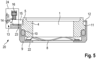
- all of the components assigned to the position sensor 20 are arranged behind the sealing surface 5 in the axial direction 4 , so that the sealing surface 5 protrudes over the housing 9 and the position sensor 20 in the axial direction. This is for example in the figure 4 shown. In this case, it is not necessary to position sensor 20 or components thereof, such as the stationary ones Sensor 13 to be detachably connected to the housing 9, because the processing of the sealing surface 5, even by lapping, is not impeded.
- the housing 9 advantageously has an opening in the radial direction, for example in the form of a notch, through which the intermediate component 15 engages radially from the outside in order to be supported on the stop surface 11 or to make the intermediate component 15 easier to attach to the slide ring 4 to be able to fasten in particular rigidly.
Landscapes
- Engineering & Computer Science (AREA)
- General Engineering & Computer Science (AREA)
- Mechanical Engineering (AREA)
- Mechanical Sealing (AREA)
- Joints Allowing Movement (AREA)
Description
- Die vorliegende Erfindung betrifft eine Gleitringdichtung zur Abdichtung wenigstens eines sich in einem stationären Bauteil und/oder einem rotierenden Bauteil erstreckenden, ein Fluid führenden Kanals und/oder Raumes gegenüber der Umgebung, gemäß dem Oberbegriff von Anspruch 1.
- Eine gattungsgemäße Gleitringdichtung ist aus
DE 34 26 539 A1 bekannt. Die Gleitringdichtung weist einen um eine Drehachse umlaufenden Gleitring auf, der sich in Axialrichtung, das heißt in Richtung der Drehachse, mit seiner Stirnseite an einem Gegenring abstützt. Die Stirnseite bildet demnach die Dichtfläche aus. - Der Gleitring unterliegt aufgrund seiner Relativdrehung und der elastischen Abstützung gegen den Gegenring einem Verschleiß. Aufgrund des Verschleißes bewegt sich der Gleitring zunehmend in der Axialrichtung. Um einen rechtzeitigen Austausch des Gleitringes sicherstellen zu können, bevor der Gleitring zu stark abgenutzt ist und damit seine Dichtwirkung verliert, wird der Verschleiß dadurch erfasst, dass radial zum axial beweglichen Gleitring eine Sonde vorgesehen ist, welche erfasst, wie weit sich der Gleitring bereits relativ zur Sonde axial bewegt hat. Hierfür kann ein magnetischer Einsatz im Gleitring oder in einem sich mit dem Gleitring bewegenden Bauteil vorgesehen sein und die Sonde als elektromagnetischer Messfühler ausgebildet sein, welcher ein Signal des magnetischen Einsatzes erfasst, wobei das Signal ein Maximum erreicht, wenn die Abriebflächen den maximalen Abrieb erreicht haben.
- Bei der dargestellten Gleitringdichtung ist die Sonde entfernt von dem umlaufenden Gleitring in einem stationären Gehäuse positioniert und wird beispielsweise radial von außen in eine Radialbohrung in dem Gehäuse eingeschraubt. Das Gehäuse trägt einen austauschbaren Sitz, der einen stationären Gegenring für den Gleitring der Gleitringdichtung ausbildet. Der Gleitring selbst ist axial beweglich und verdrehbar auf einer Welle positioniert und wird in der Axialrichtung zwischen dem Sitz und einer die Welle umschließenden sekundären Abdichtung eingeschlossen, wobei die sekundäre Abdichtung durch einen Druckbalg hergestellt wird, der zugleich den Gleitring in der Axialrichtung gegen den Gegenring drückt.
- Da der Gleitring gegenüber dem Gegenring und somit dem Gehäuse umläuft, muss sichergestellt werden, dass das Signal des magnetischen Einsatzes bei jeder möglichen Drehzahl von der Sonde sicher erfasst werden kann.
- Ein weiterer, noch gravierenderer Nachteil bei der dargestellten Ausführungsform ist, dass im Fall einer Undichtigkeit zwischen der stirnseitigen Dichtfläche des Gleitringes und dem Gegenring, beispielsweise durch eine Unebenheit oder einen nachträglich eingebrachten Schaden in der Dichtfläche des Gleitringes, eine vollständige Demontage der gesamten Gleitringdichtung notwendig ist, um die Stirnseite plan bearbeiten zu können. Anschließend ist eine erneute Ausrichtung der verschiedenen Elemente der Gleitringdichtung bei der erneuen Montage erforderlich.
-
US 2017/045144 A1 offenbart eine trockene Gasdichtung, die in Gaskompressoren in der Öl- und Gasindustrie verwendet wird. Diese Dichtung wird derart betrieben, dass sich ein dynamischer Gasfilm zwischen der umlaufenden und der stationären Dichtfläche einstellt. Hierfür muss ein Spalt zwischen den beiden Dichtflächen aufrechterhalten werden. -
EP 3 376 079 A1 offenbart ebenfalls eine trockene Gasdichtung, bei der ein Spalt zwischen den Dichtflächen eingestellt werden muss. Eine weitere Gasdichtung, bei der sich die Dichtflächen nicht berühren, wird inUS 2009/290971 A1 offenbart. - Der vorliegenden Erfindung liegt die Aufgabe zugrunde, eine Gleitringdichtung zur Abdichtung eines Kanals und/oder Raumes, der sich in einem stationären und/oder in einem rotierenden Bauteil erstreckt und ein Fluid, wie Flüssigkeit oder Gas führt, anzugeben, bei welcher eine Bearbeitung oder Nachbearbeitung der Dichtfläche des Gleitringes einfacher möglich ist. Die Gleitringdichtung soll sich bevorzugt darüber hinaus durch eine sicherere Verschleißerfassung ungeachtet der Drehzahl des rotierenden Bauteils auszeichnen.
- Eine erfindungsgemäße Gleitringdichtung zur Abdichtung wenigstens eines sich in einem stationären Bauteil und/oder einem rotierenden Bauteil erstreckenden, ein Fluid führenden Kanals und/oder Raumes gegenüber der Umgebung weist einen Gleitring auf, der sich in Axialrichtung gegen einen Gegenring dichtend abstützt. Bei einer Ausführungsform der Erfindung erstreckt sich der wenigstens eine das Fluid führende Kanal aus einem stationären Bauteil in ein rotierendes Bauteil oder aus einem rotierenden Bauteil in das stationäre Bauteil, demnach durch eine Drehdurchführung. Die Drehdurchführung dient der Übergabe des Fluids aus dem jeweiligen Kanalabschnitt des stationären Bauteils in den jeweiligen Kanalabschnitt des rotierenden, das heißt um eine Drehachse umlaufenden Bauteils oder umgekehrt. Die Erfindung kann jedoch auch unabhängig von einer Drehdurchführung in jeglichem Bauteil angewendet werden, bei dem eine Abdichtung durch eine Gleitringdichtung Verwendung findet. Insofern ist der das Fluid führende Kanal ein beliebiger Raum in einem stationären Bauteil und/oder in einem rotierenden Bauteil, der durch die Gleitringdichtung gegenüber einer Umgebung abgedichtet wird. Bei der Umgebung kann es sich um einen anderen Raum in dem Bauteil und/oder einem anderen Bauteil handeln, oder um eine Umgebung, die nicht mehr durch Gehäuseteile eingeschlossen wird. Die Umgebung kann drucklos oder druckbeaufschlagt sein. Das Fluid kann in dem Kanal und/oder Raum strömen oder stationär sein. Nur beispielhaft wird auf die Abdichtung wenigstens eines ein Fluid führenden Kanals und/oder Raumes in einer Pumpe, wie Flüssigkeitspumpe oder Gaspumpe, einem Kompressor und anderen Arbeitsmaschinen verwiesen.
- Dadurch, dass der Gleitring sich in der Axialrichtung, das heißt in Richtung der Drehachse des umlaufenden Bauteils, gegen den Gegenring dichtend abstützt, unterliegt er einem Verschleiß. Beispielsweise ist der Gleitring aus einem Kohlenstoff hergestellt beziehungsweise umfasst solchen Kohlenstoff. Um zu vermeiden, dass durch den Verschleiß, der den Gleitring in der Axialrichtung kürzt, eine Undichtigkeit beispielsweise in der Drehdurchführung entsteht, ist der Gleitring in der Axialrichtung beweglich und zur Kompensation des Verschleißes mit seiner stirnseitigen Dichtfläche elastisch gegen den Gegenring abgestützt. Ein fortschreitender Verschleiß wird somit durch zunehmende axiale Verlagerung des Gleitringes in Richtung des Gegenringes kompensiert. Zusätzlich oder alternativ kann auch der Gegenring im Bereich einer an der Dichtfläche des Gleitringes anliegenden Gegenfläche einem Abrieb beziehungsweise Verschleiß unterliegen, sodass zu dessen Kompensation eine axiale Verlagerung des Gleitringes durch dessen elastische Vorspannung erfolgt.
- Um das Ausmaß des Verschleißes beziehungsweise der bereits erfolgten axialen Bewegung des Gleitringes bewerten zu können, ist ein Positionssensor zur Erfassung der Position des Gleitringes in der Axialrichtung vorgesehen.
- Erfindungsgemäß weist der Positionssensor wenigstens einen am Gleitring befestigten oder in Axialrichtung gegen den Gleitring abgestützten und sich in der Axialrichtung mit dem Gleitring bewegenden Geber auf, sowie einen radial außerhalb des Gleitringes positionierten stationären Sensor, der die Position des Gebers in der Axialrichtung erfasst.
- Der wenigstens eine Geber, insbesondere in Form eines Magneten, kann beispielsweise in eine Bohrung, insbesondere Radialbohrung, des Gleitringes eingebracht sein.
- Erfindungsgemäß ist der stationäre Sensor an einem den Gleitring in der Axialrichtung beweglich aufnehmenden Gehäuse angeschlossen und/oder wird von diesem getragen. Der Gleitring steht in der Axialrichtung mit seiner stirnseitigen Dichtfläche gegenüber diesem Gehäuse über, das heißt die stirnseitige Dichtfläche des Gleitringes ist in der Axialrichtung außerhalb des Gehäuses und mit Abstand zu dem Gehäuse positioniert, sodass eine Bearbeitung, insbesondere Planbearbeitung der stirnseitigen Dichtfläche bei im Gehäuse montierten Gleitring möglich ist.
- Insbesondere kann ein Läppen der Dichtfläche erfolgen. Bei einem solchen Läppen kann der Gleitring mit seiner Dichtfläche auf die Läppmaschine aufgelegt werden, um die Dichtfläche besonders eben zu bearbeiten. Der Gleitring kann dabei im Gehäuse montiert sein.
- Gemäß einer Ausführungsform der Erfindung ist der stationäre Sensor lösbar am Gehäuse angeschlossen, beispielsweise mittels einer Rastverbindung. In diesem Fall kann der stationäre Sensor bei Bedarf vor der Planbearbeitung der Dichtfläche von dem Gehäuse abgenommen werden.
- Bei einer Ausführungsform der Erfindung steht der Gleitring in der Axialrichtung mit seiner stirnseitigen Dichtfläche auch gegenüber dem stationären Sensor über. In diesem Fall ist die Bearbeitung der Dichtfläche, beispielsweise durch Läppen, auch dann möglich, wenn der stationäre Sensor unlösbar am Gehäuse angeschlossen ist.
- Gemäß einer Ausführungsform der Erfindung ist der Gleitring stationär und der Gegenring läuft relativ zum Gleitring um. Stationär bedeutet dabei, dass sich der Gleitring nur in der Axialrichtung bewegen kann, nicht hingegen in Umfangsrichtung, oder zumindest nicht in der Umfangsrichtung angetrieben wird. In diesem Fall ist eine besonders sichere Signalkopplung zwischen dem Geber und dem stationären Sensor gewährleistet, unabhängig von der Drehzahl des rotierenden Bauteils.
- Der Geber kann beispielsweise wenigstens einen Magneten umfassen oder durch wenigstens einen Magneten gebildet werden, und der stationäre Sensor als Hall-Sensor ausgeführt sein, der die Position des wenigstens einen Magneten in der Axialrichtung erfasst. Ein solcher Hall-Sensor wird insbesondere von einem elektrischen Strom durchflossen und erzeugt eine Ausgangsspannung, die proportional zum Produkt aus dem Strom und einer magnetischen Flussdichte ist, die durch den dem Gleitring zugeordneten Magneten erzeugt wird.
- Besonders vorteilhaft ist der Gleitring zu seiner Abstützung gegen den Gegenring elastisch gegen das Gehäuse abgestützt. Beispielsweise umschließt das Gehäuse den Gleitring in der Umfangsrichtung und weist einen Gehäuseboden auf, der einer der Dichtfläche abgewandten Stirnseite des Gleitringes gegenübersteht. Der Gleitring kann dann mittels eines Federelementes, beispielsweise mittels einer Wellfeder oder einer anderen Druckfeder, die zwischen der Stirnseite und dem Gehäuseboden positioniert ist, elastisch am Gehäuseboden abgestützt sein.
- Beispielsweise umfasst der Gleitring einen hohlzylinderförmigen Kohlering oder ist aus einem solchen gebildet, der eine die Dichtfläche ausbildende Stirnseite aufweist. Bevorzugt weist der Kohlering ferner die genannte dem Gehäuseboden zugewandte Stirnseite auf. Der Kohlering steht dann aus dem Gehäuse in der Axialrichtung heraus.
- Gemäß einer besonders vorteilhaften Ausführungsform der Erfindung umschließt das Gehäuse den Gleitring in Umfangsrichtung und weist einen radial nach innen gerichteten Vorsprung auf. Der Gleitring weist eine dem radial nach innen gerichteten Vorsprung in der Axialrichtung gegenüberstehende Anschlagfläche auf, mit welcher der Gleitring bei einer maximal zulässigen Bewegung in der Axialrichtung an dem Vorsprung anschlägt. Dadurch wird verhindert, dass der Gleitring vollständig aus dem Gehäuse herausgedrückt wird. Bevorzugt stützt sich der Geber, insbesondere der wenigstens eine Magnet, oder ein den Geber, insbesondere dem wenigstens einen Magneten tragendes Zwischenbauteil, an dieser Anschlagfläche ab beziehungsweise liegt zur Ausrichtung des Magneten beziehungsweise des Bauteils an dieser Anschlagfläche an.
- Das Gehäuse kann eine Öffnung in Radialrichtung aufweisen, durch welche das Zwischenbauteil oder der Geber, insbesondere der wenigstens eine Magnet des Gebers, radial nach außen aus dem Gehäuse herausragt.
- Der Gleitring kann mittels eines Dichtelementes, beispielsweise eines O-Ringes, gegen das Gehäuse abgedichtet sein, insbesondere in der Radialrichtung.
- Das Gehäuse kann beispielsweise aus Stahl beziehungsweise Stahlblech hergestellt sein.
- Der Positionssensor ist insbesondere derart ausgeführt, dass er nicht nur die Endpositionen eines noch gar nicht verschlissenen Gleitringes und eines vollständig verschlissenen Gleitringes erfasst, sondern auch zwischen diesen Endpositionen vorhandene Zwischenpositionen. Insbesondere wird eine kontinuierliche Bewegung des Gleitringes in der Axialrichtung in jeder Position erfasst.
- Bei einer Ausführung des Gleitringes mit einer in Axialrichtung weisenden Anschlagfläche, die ein vollständiges Herausschieben des Gleitringes aus dem Gehäuse verhindert, steht die Stirnseite mit der Dichtfläche in der Axialrichtung gegenüber der Anschlagfläche hervor. Die Anschlagfläche kann bevorzugt radial außerhalb oder radial innerhalb der Dichtfläche vorgesehen sein.
- Das Zwischenbauteil kann beispielsweise in Form eines sich an der Anschlagfläche abstützenden Schlittens vorgesehen sein, der elastisch gegen die Anschlagfläche gedrückt wird und insbesondere in einer Gleitschiene am Gehäuse gehalten wird.
- Obwohl bei den vorstehenden und folgenden Ausführungsbeispielen der Erfindung der sich in Axialrichtung zur Kompensation seines Verschleißes bewegende Ring als Gleitring bezeichnet wurde und der vergleichsweise härtere Ring, der insbesondere nicht oder weniger verschleißt, als Gegenring bezeichnet wurde, umfasst die vorliegende Erfindung auch Ausführungsformen, bei welchen nicht oder nicht nur der sich in der Axialrichtung bewegende Ring stirnseitig verschleißt, sondern auch solche Ausführungsformen, bei welchen ein in der Axialrichtung stationärer Ring gleich weich oder weicher als der in der Axialrichtung bewegliche Ring ausgeführt ist und somit zusätzlich zu dem in der Axialrichtung beweglichen Ring oder anstelle des in der Axialrichtung beweglichen Ringes an seiner Stirnseite verschleißt.
- Die Erfindung soll nachfolgend anhand eines Ausführungsbeispiels und den Figuren exemplarisch beschrieben werden.
- Es zeigen:
- Figur 1
- eine dreidimensionale Draufsicht auf eine erfindungsgemäß ausgeführte Gleitringdichtung;
- Figur 2
- einen Axialschnitt durch die Gleitringdichtung aus der
Figur 1 ; - Figur 3
- eine Vergrößerung des Bereiches mit dem Positionssensor;
- Figur 4
- eine Darstellung analog der
Figur 3 jedoch mit unmittelbar im Gleitring montierten Magneten; - Figur 5
- eine schematische Darstellung eines lösbaren Anschlusses des Sensors am Gehäuse mittels einer Rastverbindung.
- In der
Figur 1 ist ein Ausführungsbeispiel einer erfindungsgemäßen Gleitringdichtung zur Abdichtung einer Drehdurchführung gezeigt, mit einem Kanal 1, der ein Fluid aus einem stationären Bauteil in ein rotierendes Bauteil führt. Das stationäre Bauteil ist beispielsweise in derFigur 2 schematisch angedeutet und mit 2 beziffert und das rotierende Bauteil ist ebenfalls in derFigur 2 schematisch angedeutet und mit 3 beziffert. - Wie aus den
Figuren 1 bis 5 ersichtlich ist, weist die Gleitringdichtung einen Gleitring 4 auf, der an einer axialen Stirnseite eine Dichtfläche 5 aufweist, wobei sich die Dichtfläche 5 an einer Gegenfläche 6 des rotierenden Bauteils 3 abstützt, um den Kanal 1 gegenüber der Umgebung beziehungsweise einer Leckageseite 7 abzudichten. - Der Gleitring 4 ist im Bereich seiner Dichtfläche 5 und/oder das rotierende Bauteil 3 ist im Bereich der Gegenfläche 6 aus einem verschleißenden Werkstoff hergestellt, wobei der Verschleiß durch Abrieb des Werkstoffes bei der Relativdrehung zwischen dem Gleitring 4 beziehungsweise der Dichtfläche 5 und der Gegenfläche 6 erfolgt. Um trotzdem die gewünschte Abdichtung im Bereich der Dichtfläche 5 beziehungsweise Gegenfläche 6 zu erzielen, ist der Gleitring 4 an seinem der Dichtfläche 5 abgewandten axialen Ende mittels eines Federelementes, hier einer Druckfeder oder Wellfeder 8, elastisch in einem Gehäuse 9 abgestützt. Wie man aus den
Figuren 2 ,4 und5 entnehmen kann, erfolgt die Abstützung mittels der Druckfeder oder Wellfeder beispielsweise an einem Gehäuseboden 22 des Gehäuses 9. - Der Kanal 1 verläuft in Axialrichtung durch das Gehäuse 9 und den Gleitring 4 und bevorzugt auch durch die Wellfeder 8. Zur Abdichtung ist ein O-Ring 10 zwischen dem Gleitring 4 und dem Gehäuse 9 vorgesehen.
- Der Gleitring 4 weist eine Schulter oder Anschlagfläche 11 auf, die bei einer ausfahrenden Bewegung des Gleitringes 4 in Axialrichtung aus dem Gehäuse 9 an einem radial nach innen gerichteten Vorsprung 12 des Gehäuses 9 anschlägt, um ein weiteres Ausfahren des Gleitringes 4 aus dem Gehäuse 9 zu verhindern.
- Am Gehäuse 9 ist ein stationärer Sensor 13 angeschlossen, der radial außerhalb zu einem Magneten 14 positioniert ist und als Hall-Sensor ausgeführt ist, der eine axiale Position des Magneten 14 und damit des Gleitringes 4 erfasst. Der Magnet 14 ist insbesondere unmittelbar am Gleitring 4 angeschlossen, siehe die
Figur 4 , oder über ein Zwischenbauteil 15, das sich in der Axialrichtung gemeinsam mit dem Gleitring 4 bewegt und den Magneten 14 trägt, siehe dieFiguren 1 bis 3 . - Bevorzugt stützt sich der Magnet 14 oder das Zwischenbauteil 15 in Axialrichtung an der Anschlagfläche 11 ab.
- Im in den
Figuren 1 bis 3 gezeigten Ausführungsbeispiel ist das Zwischenbauteil 15 mittels eines Federelementes 16 elastisch gegen die Anschlagfläche 11 abgestützt. Alternativ käme auch ein starrer Anschluss des Zwischenbauteils 15 am Gleitring 4 in Betracht. - Im in der
Figur 4 gezeigten Ausführungsbeispiel ist ein sich in Umfangsrichtung über den ganzen Umfang des Gleitringes 4 erstreckender Magnet 14 vorgesehen oder es sind mehrere Magneten 14 über dem Umfang des Gleitringes 4 verteilt angeordnet, um eine Verdrehung des Gleitringes 4 relative zum stationären Sensor 13 zu ermöglichen, ohne die Funktionsweise der Positionserfassung zu beeinträchtigen. Dies ist jedoch nicht zwingend. - Der stationäre Sensor 13 weist ein Sensorgehäuse 18 auf, in welches ein Temperatursensor 19 integriert ist. Der Temperatursensor 19 erfasst die Temperatur eines aus dem Kanal 1 über die Dichtfläche 5 übertretenden Leckagestroms des im Kanal 1 geführten Fluids, wobei die erfasste Temperatur abhängig von der Größe des Leckagestromes ist, weil durch die Anordnung des Temperatursensors 19 beziehungsweise des stationären Sensors 13 im Leckagestrom mit zunehmendem Leckagestrom der Wärmeübergang zwischen dem Leckagestrom und dem stationären Sensor 13 beziehungsweise Temperatursensor 19 vergrößert wird.
- Der stationäre Sensor 19 bildet ferner zusammen mit dem Magneten 14 einen Positionssensor 20 zur Erfassung der Position des Gleitringes 4 in der Axialrichtung.
- Der Positionssensor 20 ist als Hall-Sensor ausgeführt und der Temperatursensor 19 wird ferner verwendet, um die Temperaturabhängigkeit der vom Hall-Sensor erfassten Messgröße zu kompensieren. Hierfür kann im Sensorgehäuse 18 oder außerhalb von diesem eine Steuervorrichtung 21 vorgesehen sein, die die Positionserfassung und insbesondere die Leckagestromerfassung steuert.
- Um die Dichtfläche 5 planbearbeiten zu können, ist der stationäre Sensor 13 bevorzugt lösbar am Gehäuse 9 angeschlossen, beispielsweise mittels einer Rastverbindung. Bei den Darstellungen in den
Figuren 1 bis 3 ist die Rastverbindung nicht im Einzelnen gezeigt. In derFigur 5 ist die Rastverbindung mit 23 beziffert. Diese Rastverbindung 23 umfasst wenigstens eine Rastöffnung im Gehäuse 9 und wenigstens eine Rastnase in einem zumindest den stationären Sensor tragenden Träger. Zusätzlich oder alternativ können die wenigstens eine Rastöffnung auch in dem Träger und die wenigstens eine Rastnase in dem Gehäuse vorgesehen sein. Wenn, wie in derFigur 5 gezeigt ist, auch weitere dem Positionssensor 20 zugeordnete Bauteile in der Axialrichtung über die Dichtfläche 5 des Gleitrings 4 hinausstehende Bauteile vorgesehen sind, so werden diese ebenfalls im Träger 24 gelagert, beispielsweise, wenn dieses vorgesehen ist, das Federelement 16 und/oder das Zwischenbauteil 15. Alle in der Axialrichtung über die Dichtfläche 5 herausstehenden Bauteile können gemeinsam mit dem Träger 24 vom Gehäuse 9 abgenommen werden, um die gewünschte Bearbeitung der Dichtfläche 5 zu ermöglichen. Prinzipiell könnten auch mehrere abnehmbare Träger für die verschiedenen Bauteile vorgesehen sein, und/oder ein oder mehrere Bauteile könnten direkt abnehmbar am Gehäuse angeschlossen sein. - Alternativ sind alle dem Positionssensor 20 zugeordneten Bauteile in der Axialrichtung 4 hinter der Dichtfläche 5 angeordnet, sodass die Dichtfläche 5 in der Axialrichtung über das Gehäuse 9 und den Positionssensor 20 vorsteht. Dies ist beispielsweise in der
Figur 4 gezeigt. In diesem Fall ist es nicht notwendig, den Positionssensor 20 beziehungsweise Bauteile desselben, wie den stationären Sensor 13, lösbar am Gehäuse 9 anzuschließen, weil die Bearbeitung der Dichtfläche 5, auch durch Läppen, nicht behindert wird. - Bei einem nicht näher gezeigten lösbaren Anschluss gemäß der
Figur 1 ist es möglich, den stationären Sensor 13, insbesondere zusammen mit dem Zwischenbauteil 15 und der das Zwischenbauteil 15 verschiebbar haltenden Gleitschiene 17 vom Gehäuse 9 abzunehmen. Anschließend kann die Dichtfläche 5 beispielsweise geläppt werden. - Bei einer Ausführungsform mit Zwischenbauteil 15 weist das Gehäuse 9 vorteilhaft eine Öffnung in Radialrichtung, beispielsweise in Form einer Ausklinkung, auf, durch welche das Zwischenbauteil 15 radial von außen eingreift, um sich an der Anschlagfläche 11 abzustützen oder um das Zwischenbauteil 15 leichter am Gleitring 4 insbesondere starr befestigen zu können.
-
- 1
- Kanal
- 2
- stationäres Bauteil
- 3
- rotierendes Bauteil
- 4
- Gleitring
- 5
- Dichtfläche
- 6
- Gegenfläche
- 7
- Leckageseite
- 8
- Wellfeder
- 9
- Gehäuse
- 10
- O-Ring
- 11
- Anschlagfläche
- 12
- Vorsprung
- 13
- stationärer Sensor
- 14
- Magnet
- 15
- Zwischenbauteil
- 16
- Federelement
- 17
- Gleitschiene
- 18
- Sensorgehäuse
- 19
- Temperatursensor
- 20
- Positionssensor
- 21
- Steuervorrichtung
- 22
- Gehäuseboden
- 23
- Rastverbindung
- 24
- Träger
Claims (11)
- Gleitringdichtung zur Abdichtung wenigstens eines sich in einem stationären Bauteil (2) und/oder einem rotierenden Bauteil (3) erstreckenden, ein Fluid führenden Kanals (1) und/oder Raumes gegenüber der Umgebung,mit einem Gleitring (4) und einem Gegenring, wobei sich der Gleitring (4) in Axialrichtung gegen den Gegenring dichtend abstützt und zur Kompensation eines Verschleißes an seiner stirnseitigen Dichtfläche (5) oder an einer Gegenfläche elastisch und in der Axialrichtung beweglich mit dieser Dichtfläche (5) gegen den Gegenring abgestützt ist;mit einem Positionssensor (20) zur Erfassung der Position des Gleitringes (4) in der Axialrichtung; wobeider Positionssensor (20) wenigstens einen am Gleitring (4) befestigten oder in der Axialrichtung gegen den Gleitring (4) abgestützten, sich in der Axialrichtung mit dem Gleitring (4) bewegenden Geber und einen radial außerhalb des Gleitringes (4) positionierten stationären Sensor (13), der die Position des Gebers in der Axialrichtung erfasst, umfasst;dadurch gekennzeichnet, dassder stationäre Sensor (13) an einem den Gleitring (4) in der Axialrichtung beweglich aufnehmenden Gehäuse (9) angeschlossen ist und/oder von diesem getragen wird, gegenüber welchem der Gleitring (4) in der Axialrichtung mit seiner stirnseitigen Dichtfläche (5) übersteht.
- Gleitringdichtung gemäß Anspruch 1, dadurch gekennzeichnet, dass der stationäre Sensor (13) lösbar am Gehäuse (9) angeschlossen ist.
- Gleitringdichtung gemäß Anspruch 2, dadurch gekennzeichnet, dass der stationäre Sensor (13) mittels einer Rastverbindung (23) am Gehäuse (9) angeschlossen ist.
- Gleitringdichtung gemäß einem der Ansprüche 1 bis 3, dadurch gekennzeichnet, dass der Gleitring (4) in der Axialrichtung mit seiner stirnseitigen Dichtfläche (5) gegenüber dem stationären Sensor (13) übersteht.
- Gleitringdichtung gemäß einem der Ansprüche 1 bis 4, dadurch gekennzeichnet, dass der Gleitring (4) stationär ist und der Gegenring relativ zum Gleitring (4) umläuft.
- Gleitringdichtung gemäß einem der Ansprüche 1 bis 5, dadurch gekennzeichnet, dass der Geber wenigstens einen Magneten (14) umfasst oder durch diesen gebildet wird und der stationäre Sensor (13) als Hall-Sensor ausgeführt ist, der die Position des Magneten (14) in der Axialrichtung erfasst.
- Gleitringdichtung gemäß einem der Ansprüche 1 bis 6, dadurch gekennzeichnet, dass der Gleitring (4) zu seiner Abstützung gegen den Gegenring elastisch gegen das Gehäuse (9) abgestützt ist.
- Gleitringdichtung gemäß Anspruch 7, dadurch gekennzeichnet, dass das Gehäuse (9) den Gleitring (4) in Umfangsrichtung umschließt und einen Gehäuseboden (22) aufweist, der einer der Dichtfläche (5) abgewandten Stirnseite des Gleitringes (4) gegenübersteht, und der Gleitring (4) mittels eines Federelementes, insbesondere mittels einer Wellfeder (8), zwischen der Stirnseite und dem Gehäuseboden (22) elastisch am Gehäuseboden (22) abgestützt ist.
- Gleitringdichtung gemäß einem der Ansprüche 1 bis 8, dadurch gekennzeichnet, dass der Gleitring (4) einen hohlzylinderförmigen Kohlering umfasst oder aus einem solchen gebildet ist, der eine die Dichtfläche (5) ausbildende Stirnseite aufweist, und insbesondere ferner die dem Gehäuseboden (22) zugewandte Stirnseite aufweist.
- Gleitringdichtung gemäß einem der Ansprüche 1 bis 9, dadurch gekennzeichnet, dass das Gehäuse (9) den Gleitring (4) in Umfangsrichtung umschließt und einen radial nach innen gerichteten Vorsprung (12) aufweist, und der Gleitring (4) eine dem radial nach innen gerichteten Vorsprung (12) in der Axialrichtung gegenüberstehende Anschlagfläche (11) aufweist, mit welcher der Gleitring (4) bei einer maximal zulässigen Bewegung in der Axialrichtung an dem Vorsprung (12) anschlägt, wobei der Geber, insbesondere der Magnet (14) oder ein den Geber, insbesondere den Magneten (14) tragendes Zwischenbauteil (15) sich ebenfalls an der Anschlagfläche (11) abstützt oder an dieser anliegt.
- Gleitringdichtung gemäß Anspruch 10, dadurch gekennzeichnet, dass das Gehäuse (9) eine Öffnung in Radialrichtung aufweist, durch welche das Zwischenbauteil (15) oder der Geber, insbesondere der Magnet (14), radial nach außen aus dem Gehäuse (9) herausragt.
Applications Claiming Priority (1)
| Application Number | Priority Date | Filing Date | Title |
|---|---|---|---|
| DE102017218689.5A DE102017218689A1 (de) | 2017-10-19 | 2017-10-19 | Gleitringdichtung zur Abdichtung eines ein Fluid führenden Kanals und/oder Raumes |
Publications (3)
| Publication Number | Publication Date |
|---|---|
| EP3473898A1 EP3473898A1 (de) | 2019-04-24 |
| EP3473898B1 true EP3473898B1 (de) | 2023-03-22 |
| EP3473898B8 EP3473898B8 (de) | 2023-05-17 |
Family
ID=63720525
Family Applications (1)
| Application Number | Title | Priority Date | Filing Date |
|---|---|---|---|
| EP18197859.4A Active EP3473898B8 (de) | 2017-10-19 | 2018-10-01 | Gleitringdichtung zur abdichtung eines ein fluid führenden kanals und/oder raumes |
Country Status (5)
| Country | Link |
|---|---|
| EP (1) | EP3473898B8 (de) |
| DE (1) | DE102017218689A1 (de) |
| ES (1) | ES2943311T3 (de) |
| FI (1) | FI3473898T3 (de) |
| PT (1) | PT3473898T (de) |
Cited By (1)
| Publication number | Priority date | Publication date | Assignee | Title |
|---|---|---|---|---|
| DE102023109573B3 (de) | 2023-04-17 | 2024-07-25 | Christian Maier GmbH & Co. KG | Drehdurchführung mit einer Gleitringdichtung und einem Verschleißsensor für die Gleitringdichtung und Verfahren zum Kalibrieren eines Verschleißsensors in einer Drehdurchführung |
Families Citing this family (1)
| Publication number | Priority date | Publication date | Assignee | Title |
|---|---|---|---|---|
| DE102018215736B4 (de) | 2018-09-17 | 2025-11-13 | Christian Maier GmbH & Co. KG, Maschinenfabrik | Drehdurchführung mit Gleitringdichtung |
Citations (2)
| Publication number | Priority date | Publication date | Assignee | Title |
|---|---|---|---|---|
| CN103791095A (zh) * | 2014-03-06 | 2014-05-14 | 重庆广播电视大学 | 自动预紧的机械密封总成 |
| DE102013220429A1 (de) * | 2013-10-10 | 2015-04-30 | Eagleburgmann Germany Gmbh & Co. Kg | Gleitringdichtungsanordnung mit optischer Überwachungseinrichtung und Verfahren zum Überwachen eines Dichtspaltes einer Gleitringdichtungsanordnung |
Family Cites Families (9)
| Publication number | Priority date | Publication date | Assignee | Title |
|---|---|---|---|---|
| IT1149725B (it) * | 1982-02-02 | 1986-12-10 | S I E T T E Soc Impianti Elett | Guarnizione di tenuta frontale a strisciamento,in particolare per pompe di circolazione del liquido di raffreddamento di motori a combustione interna |
| GB8319550D0 (en) | 1983-07-20 | 1983-08-24 | Grange Packing Ltd | Seal wear indicator |
| EP0454374B1 (de) * | 1990-04-23 | 1994-12-21 | Tanken Seiko Kabushiki Kaisha | Verfahren zur Vorhersage von Abweichungen in mechanischen Dichtungen und Gerät zu ihrer Vorhersage |
| JPH04327069A (ja) * | 1991-04-26 | 1992-11-16 | Hitachi Ltd | 軸封装置の摩耗量検出装置 |
| JP2681725B2 (ja) * | 1992-04-15 | 1997-11-26 | 株式会社タンケンシールセーコウ | メカニカルシールの挙動監視装置 |
| JP3256726B2 (ja) * | 1993-02-19 | 2002-02-12 | 株式会社日立製作所 | モニタリング付メカニカルシールを備えた容器 |
| WO2009143213A2 (en) * | 2008-05-21 | 2009-11-26 | John Crane Inc. | Seal monitoring and control system |
| US10018274B2 (en) * | 2015-08-10 | 2018-07-10 | Exxonmobil Upstream Research Company | Device and method for magnetically controlled dry gas seal |
| IT201700029982A1 (it) * | 2017-03-17 | 2018-09-17 | Nuovo Pignone Tecnologie Srl | Tenuta a gas |
-
2017
- 2017-10-19 DE DE102017218689.5A patent/DE102017218689A1/de not_active Ceased
-
2018
- 2018-10-01 FI FIEP18197859.4T patent/FI3473898T3/fi active
- 2018-10-01 ES ES18197859T patent/ES2943311T3/es active Active
- 2018-10-01 PT PT181978594T patent/PT3473898T/pt unknown
- 2018-10-01 EP EP18197859.4A patent/EP3473898B8/de active Active
Patent Citations (2)
| Publication number | Priority date | Publication date | Assignee | Title |
|---|---|---|---|---|
| DE102013220429A1 (de) * | 2013-10-10 | 2015-04-30 | Eagleburgmann Germany Gmbh & Co. Kg | Gleitringdichtungsanordnung mit optischer Überwachungseinrichtung und Verfahren zum Überwachen eines Dichtspaltes einer Gleitringdichtungsanordnung |
| CN103791095A (zh) * | 2014-03-06 | 2014-05-14 | 重庆广播电视大学 | 自动预紧的机械密封总成 |
Cited By (2)
| Publication number | Priority date | Publication date | Assignee | Title |
|---|---|---|---|---|
| DE102023109573B3 (de) | 2023-04-17 | 2024-07-25 | Christian Maier GmbH & Co. KG | Drehdurchführung mit einer Gleitringdichtung und einem Verschleißsensor für die Gleitringdichtung und Verfahren zum Kalibrieren eines Verschleißsensors in einer Drehdurchführung |
| EP4450858A1 (de) | 2023-04-17 | 2024-10-23 | Christian Maier GmbH & Co. KG Maschinenfabrik | Drehdurchführung mit einer gleitringdichtung und einem verschleisssensor für die gleitringdichtung und verfahren zum kalibrieren eines verschleisssensors in einer drehdurchführung |
Also Published As
| Publication number | Publication date |
|---|---|
| FI3473898T3 (fi) | 2023-05-05 |
| PT3473898T (pt) | 2023-05-05 |
| DE102017218689A1 (de) | 2019-04-25 |
| EP3473898A1 (de) | 2019-04-24 |
| EP3473898B8 (de) | 2023-05-17 |
| ES2943311T3 (es) | 2023-06-12 |
Similar Documents
| Publication | Publication Date | Title |
|---|---|---|
| EP3698073B1 (de) | Gleitringdichtung zur abdichtung eines ein fluid führenden kanals und/oder raumes und verfahren zum überwachen des verschleisses einer gleitrindichtung | |
| DE102009004035B4 (de) | Überwachung einer Abdichtungsanordnung, insbesondere eines Gaskompressors oder -expanders | |
| DE102018206219B3 (de) | Dynamische Dichtung und Drehdurchführung mit einer solchen dynamischen Dichtung | |
| EP2739872B1 (de) | Hydraulikzylinder, insbesondere für eine kupplungsbetätigungseinrichtung in einem kraftfahrzeug | |
| DE102015209428A1 (de) | Dichtungsanordnung zum Abdichten eines Raumes zwischen einem Gehäuse und einem Bauteil gegen ein flüssiges Medium | |
| DE102016208697A1 (de) | Rotationsdichtungsanordnung mit druckaktivierbarer Rotationsdichtung sowie Rotationsdichtung | |
| EP3473898A1 (de) | Gleitringdichtung zur abdichtung eines ein fluid führenden kanals und/oder raumes | |
| DE102010033647B4 (de) | Vorrichtung zum Abdichten einer Stange gegenüber einem Medium und Verfahren zum Abdichten einer Stange gegenüber einem Medium | |
| DE102013003159B4 (de) | Gleitringdichtung mit Encoderfunktion | |
| EP0829663A1 (de) | Gleitringdichtung | |
| DE102010019531A1 (de) | Kupplungsausrücklager | |
| DE202008004116U1 (de) | Gleitringdichtungsanordnung mit Leiteinrichtung | |
| DE202016102216U1 (de) | Düse mit Gleitspaltdichtung | |
| EP0472929B1 (de) | Verwendung einer Dichtungsanordnung | |
| DE102009011224A1 (de) | Kolben und damit ausgestatteter fluidischer Linearantrieb | |
| WO2009155945A1 (de) | Fluidtechnisches gerät | |
| WO2019158154A1 (de) | Aktuator zur betätigung einer reibkupplung | |
| DE2918418C2 (de) | Stevenrohrabdichtung mit einer Radialdichtung | |
| DE112004002198T5 (de) | Kupplungsstellglieder | |
| DE102010045613A1 (de) | Dichtung, insbesondere für Drehdurchführungen | |
| DE10327723B3 (de) | Dreheinführung | |
| DE102017004480B4 (de) | Dichtring und Dichtungsanordnung, die den Dichtring umfasst | |
| EP4411162B1 (de) | Bremse mit einer einrichtung zur ermittlung einer verschleissgrenze | |
| DE102023134422B3 (de) | Linearlager für einen Linearsteller | |
| DE804745C (de) | Wellenabdichtung fuer hydraulische Geraete |
Legal Events
| Date | Code | Title | Description |
|---|---|---|---|
| PUAI | Public reference made under article 153(3) epc to a published international application that has entered the european phase |
Free format text: ORIGINAL CODE: 0009012 |
|
| STAA | Information on the status of an ep patent application or granted ep patent |
Free format text: STATUS: THE APPLICATION HAS BEEN PUBLISHED |
|
| AK | Designated contracting states |
Kind code of ref document: A1 Designated state(s): AL AT BE BG CH CY CZ DE DK EE ES FI FR GB GR HR HU IE IS IT LI LT LU LV MC MK MT NL NO PL PT RO RS SE SI SK SM TR |
|
| AX | Request for extension of the european patent |
Extension state: BA ME |
|
| STAA | Information on the status of an ep patent application or granted ep patent |
Free format text: STATUS: REQUEST FOR EXAMINATION WAS MADE |
|
| 17P | Request for examination filed |
Effective date: 20190924 |
|
| RBV | Designated contracting states (corrected) |
Designated state(s): AL AT BE BG CH CY CZ DE DK EE ES FI FR GB GR HR HU IE IS IT LI LT LU LV MC MK MT NL NO PL PT RO RS SE SI SK SM TR |
|
| STAA | Information on the status of an ep patent application or granted ep patent |
Free format text: STATUS: EXAMINATION IS IN PROGRESS |
|
| 17Q | First examination report despatched |
Effective date: 20200928 |
|
| 17Q | First examination report despatched |
Effective date: 20201001 |
|
| RAP3 | Party data changed (applicant data changed or rights of an application transferred) |
Owner name: CHRISTIAN MAIER GMBH & CO. KG |
|
| GRAP | Despatch of communication of intention to grant a patent |
Free format text: ORIGINAL CODE: EPIDOSNIGR1 |
|
| STAA | Information on the status of an ep patent application or granted ep patent |
Free format text: STATUS: GRANT OF PATENT IS INTENDED |
|
| GRAS | Grant fee paid |
Free format text: ORIGINAL CODE: EPIDOSNIGR3 |
|
| INTG | Intention to grant announced |
Effective date: 20230113 |
|
| GRAA | (expected) grant |
Free format text: ORIGINAL CODE: 0009210 |
|
| STAA | Information on the status of an ep patent application or granted ep patent |
Free format text: STATUS: THE PATENT HAS BEEN GRANTED |
|
| AK | Designated contracting states |
Kind code of ref document: B1 Designated state(s): AL AT BE BG CH CY CZ DE DK EE ES FI FR GB GR HR HU IE IS IT LI LT LU LV MC MK MT NL NO PL PT RO RS SE SI SK SM TR |
|
| REG | Reference to a national code |
Ref country code: GB Ref legal event code: FG4D Free format text: NOT ENGLISH |
|
| REG | Reference to a national code |
Ref country code: CH Ref legal event code: EP |
|
| GRAT | Correction requested after decision to grant or after decision to maintain patent in amended form |
Free format text: ORIGINAL CODE: EPIDOSNCDEC |
|
| REG | Reference to a national code |
Ref country code: IE Ref legal event code: FG4D Free format text: LANGUAGE OF EP DOCUMENT: GERMAN |
|
| REG | Reference to a national code |
Ref country code: DE Ref legal event code: R096 Ref document number: 502018011802 Country of ref document: DE |
|
| REG | Reference to a national code |
Ref country code: AT Ref legal event code: REF Ref document number: 1555487 Country of ref document: AT Kind code of ref document: T Effective date: 20230415 |
|
| REG | Reference to a national code |
Ref country code: CH Ref legal event code: PK Free format text: BERICHTIGUNG B8 |
|
| REG | Reference to a national code |
Ref country code: PT Ref legal event code: SC4A Ref document number: 3473898 Country of ref document: PT Date of ref document: 20230505 Kind code of ref document: T Free format text: AVAILABILITY OF NATIONAL TRANSLATION Effective date: 20230427 |
|
| REG | Reference to a national code |
Ref country code: SE Ref legal event code: TRGR |
|
| RAP4 | Party data changed (patent owner data changed or rights of a patent transferred) |
Owner name: CHRISTIAN MAIER GMBH & CO KG, MASCHINENFABRIK |
|
| REG | Reference to a national code |
Ref country code: NL Ref legal event code: FP |
|
| REG | Reference to a national code |
Ref country code: ES Ref legal event code: FG2A Ref document number: 2943311 Country of ref document: ES Kind code of ref document: T3 Effective date: 20230612 |
|
| REG | Reference to a national code |
Ref country code: NL Ref legal event code: HC Owner name: CHRISTIAN MAIER GMBH & CO KG, MASCHINENFABRIK; DE Free format text: DETAILS ASSIGNMENT: CHANGE OF OWNER(S), CHANGE OF OWNER(S) NAME; FORMER OWNER NAME: CHRISTIAN MAIER GMBH & CO. KG Effective date: 20230525 |
|
| P01 | Opt-out of the competence of the unified patent court (upc) registered |
Effective date: 20230524 |
|
| REG | Reference to a national code |
Ref country code: LT Ref legal event code: MG9D |
|
| PG25 | Lapsed in a contracting state [announced via postgrant information from national office to epo] |
Ref country code: RS Free format text: LAPSE BECAUSE OF FAILURE TO SUBMIT A TRANSLATION OF THE DESCRIPTION OR TO PAY THE FEE WITHIN THE PRESCRIBED TIME-LIMIT Effective date: 20230322 Ref country code: NO Free format text: LAPSE BECAUSE OF FAILURE TO SUBMIT A TRANSLATION OF THE DESCRIPTION OR TO PAY THE FEE WITHIN THE PRESCRIBED TIME-LIMIT Effective date: 20230622 Ref country code: LV Free format text: LAPSE BECAUSE OF FAILURE TO SUBMIT A TRANSLATION OF THE DESCRIPTION OR TO PAY THE FEE WITHIN THE PRESCRIBED TIME-LIMIT Effective date: 20230322 Ref country code: LT Free format text: LAPSE BECAUSE OF FAILURE TO SUBMIT A TRANSLATION OF THE DESCRIPTION OR TO PAY THE FEE WITHIN THE PRESCRIBED TIME-LIMIT Effective date: 20230322 Ref country code: HR Free format text: LAPSE BECAUSE OF FAILURE TO SUBMIT A TRANSLATION OF THE DESCRIPTION OR TO PAY THE FEE WITHIN THE PRESCRIBED TIME-LIMIT Effective date: 20230322 |
|
| PG25 | Lapsed in a contracting state [announced via postgrant information from national office to epo] |
Ref country code: GR Free format text: LAPSE BECAUSE OF FAILURE TO SUBMIT A TRANSLATION OF THE DESCRIPTION OR TO PAY THE FEE WITHIN THE PRESCRIBED TIME-LIMIT Effective date: 20230623 |
|
| PG25 | Lapsed in a contracting state [announced via postgrant information from national office to epo] |
Ref country code: SM Free format text: LAPSE BECAUSE OF FAILURE TO SUBMIT A TRANSLATION OF THE DESCRIPTION OR TO PAY THE FEE WITHIN THE PRESCRIBED TIME-LIMIT Effective date: 20230322 Ref country code: RO Free format text: LAPSE BECAUSE OF FAILURE TO SUBMIT A TRANSLATION OF THE DESCRIPTION OR TO PAY THE FEE WITHIN THE PRESCRIBED TIME-LIMIT Effective date: 20230322 Ref country code: EE Free format text: LAPSE BECAUSE OF FAILURE TO SUBMIT A TRANSLATION OF THE DESCRIPTION OR TO PAY THE FEE WITHIN THE PRESCRIBED TIME-LIMIT Effective date: 20230322 |
|
| PG25 | Lapsed in a contracting state [announced via postgrant information from national office to epo] |
Ref country code: SK Free format text: LAPSE BECAUSE OF FAILURE TO SUBMIT A TRANSLATION OF THE DESCRIPTION OR TO PAY THE FEE WITHIN THE PRESCRIBED TIME-LIMIT Effective date: 20230322 Ref country code: PL Free format text: LAPSE BECAUSE OF FAILURE TO SUBMIT A TRANSLATION OF THE DESCRIPTION OR TO PAY THE FEE WITHIN THE PRESCRIBED TIME-LIMIT Effective date: 20230322 Ref country code: IS Free format text: LAPSE BECAUSE OF FAILURE TO SUBMIT A TRANSLATION OF THE DESCRIPTION OR TO PAY THE FEE WITHIN THE PRESCRIBED TIME-LIMIT Effective date: 20230722 |
|
| REG | Reference to a national code |
Ref country code: DE Ref legal event code: R097 Ref document number: 502018011802 Country of ref document: DE |
|
| PLBE | No opposition filed within time limit |
Free format text: ORIGINAL CODE: 0009261 |
|
| STAA | Information on the status of an ep patent application or granted ep patent |
Free format text: STATUS: NO OPPOSITION FILED WITHIN TIME LIMIT |
|
| PG25 | Lapsed in a contracting state [announced via postgrant information from national office to epo] |
Ref country code: SI Free format text: LAPSE BECAUSE OF FAILURE TO SUBMIT A TRANSLATION OF THE DESCRIPTION OR TO PAY THE FEE WITHIN THE PRESCRIBED TIME-LIMIT Effective date: 20230322 Ref country code: DK Free format text: LAPSE BECAUSE OF FAILURE TO SUBMIT A TRANSLATION OF THE DESCRIPTION OR TO PAY THE FEE WITHIN THE PRESCRIBED TIME-LIMIT Effective date: 20230322 Ref country code: CZ Free format text: LAPSE BECAUSE OF FAILURE TO SUBMIT A TRANSLATION OF THE DESCRIPTION OR TO PAY THE FEE WITHIN THE PRESCRIBED TIME-LIMIT Effective date: 20230322 |
|
| 26N | No opposition filed |
Effective date: 20240102 |
|
| PG25 | Lapsed in a contracting state [announced via postgrant information from national office to epo] |
Ref country code: MC Free format text: LAPSE BECAUSE OF FAILURE TO SUBMIT A TRANSLATION OF THE DESCRIPTION OR TO PAY THE FEE WITHIN THE PRESCRIBED TIME-LIMIT Effective date: 20230322 |
|
| PG25 | Lapsed in a contracting state [announced via postgrant information from national office to epo] |
Ref country code: LU Free format text: LAPSE BECAUSE OF NON-PAYMENT OF DUE FEES Effective date: 20231001 |
|
| GBPC | Gb: european patent ceased through non-payment of renewal fee |
Effective date: 20231001 |
|
| PG25 | Lapsed in a contracting state [announced via postgrant information from national office to epo] |
Ref country code: LU Free format text: LAPSE BECAUSE OF NON-PAYMENT OF DUE FEES Effective date: 20231001 |
|
| PG25 | Lapsed in a contracting state [announced via postgrant information from national office to epo] |
Ref country code: GB Free format text: LAPSE BECAUSE OF NON-PAYMENT OF DUE FEES Effective date: 20231001 |
|
| PG25 | Lapsed in a contracting state [announced via postgrant information from national office to epo] |
Ref country code: GB Free format text: LAPSE BECAUSE OF NON-PAYMENT OF DUE FEES Effective date: 20231001 |
|
| PG25 | Lapsed in a contracting state [announced via postgrant information from national office to epo] |
Ref country code: IE Free format text: LAPSE BECAUSE OF NON-PAYMENT OF DUE FEES Effective date: 20231001 |
|
| PG25 | Lapsed in a contracting state [announced via postgrant information from national office to epo] |
Ref country code: IE Free format text: LAPSE BECAUSE OF NON-PAYMENT OF DUE FEES Effective date: 20231001 |
|
| PG25 | Lapsed in a contracting state [announced via postgrant information from national office to epo] |
Ref country code: BG Free format text: LAPSE BECAUSE OF FAILURE TO SUBMIT A TRANSLATION OF THE DESCRIPTION OR TO PAY THE FEE WITHIN THE PRESCRIBED TIME-LIMIT Effective date: 20230322 |
|
| PG25 | Lapsed in a contracting state [announced via postgrant information from national office to epo] |
Ref country code: BG Free format text: LAPSE BECAUSE OF FAILURE TO SUBMIT A TRANSLATION OF THE DESCRIPTION OR TO PAY THE FEE WITHIN THE PRESCRIBED TIME-LIMIT Effective date: 20230322 |
|
| PG25 | Lapsed in a contracting state [announced via postgrant information from national office to epo] |
Ref country code: CY Free format text: LAPSE BECAUSE OF FAILURE TO SUBMIT A TRANSLATION OF THE DESCRIPTION OR TO PAY THE FEE WITHIN THE PRESCRIBED TIME-LIMIT; INVALID AB INITIO Effective date: 20181001 |
|
| PG25 | Lapsed in a contracting state [announced via postgrant information from national office to epo] |
Ref country code: HU Free format text: LAPSE BECAUSE OF FAILURE TO SUBMIT A TRANSLATION OF THE DESCRIPTION OR TO PAY THE FEE WITHIN THE PRESCRIBED TIME-LIMIT; INVALID AB INITIO Effective date: 20181001 |
|
| REG | Reference to a national code |
Ref country code: CH Ref legal event code: U11 Free format text: ST27 STATUS EVENT CODE: U-0-0-U10-U11 (AS PROVIDED BY THE NATIONAL OFFICE) Effective date: 20251101 |
|
| PGFP | Annual fee paid to national office [announced via postgrant information from national office to epo] |
Ref country code: NL Payment date: 20251031 Year of fee payment: 8 |
|
| PGFP | Annual fee paid to national office [announced via postgrant information from national office to epo] |
Ref country code: PT Payment date: 20251031 Year of fee payment: 8 |
|
| PG25 | Lapsed in a contracting state [announced via postgrant information from national office to epo] |
Ref country code: TR Free format text: LAPSE BECAUSE OF FAILURE TO SUBMIT A TRANSLATION OF THE DESCRIPTION OR TO PAY THE FEE WITHIN THE PRESCRIBED TIME-LIMIT Effective date: 20230322 |
|
| PGFP | Annual fee paid to national office [announced via postgrant information from national office to epo] |
Ref country code: DE Payment date: 20251112 Year of fee payment: 8 |
|
| PGFP | Annual fee paid to national office [announced via postgrant information from national office to epo] |
Ref country code: AT Payment date: 20251104 Year of fee payment: 8 |
|
| PGFP | Annual fee paid to national office [announced via postgrant information from national office to epo] |
Ref country code: FI Payment date: 20251031 Year of fee payment: 8 Ref country code: IT Payment date: 20251031 Year of fee payment: 8 |
|
| PGFP | Annual fee paid to national office [announced via postgrant information from national office to epo] |
Ref country code: FR Payment date: 20251031 Year of fee payment: 8 |
|
| PGFP | Annual fee paid to national office [announced via postgrant information from national office to epo] |
Ref country code: BE Payment date: 20251031 Year of fee payment: 8 |
|
| PGFP | Annual fee paid to national office [announced via postgrant information from national office to epo] |
Ref country code: SE Payment date: 20251031 Year of fee payment: 8 Ref country code: CH Payment date: 20251101 Year of fee payment: 8 |
|
| PGFP | Annual fee paid to national office [announced via postgrant information from national office to epo] |
Ref country code: ES Payment date: 20251103 Year of fee payment: 8 |