EP3473798B1 - Gewindeverbindung, teilweise in einem selbsthemmenden eingriff - Google Patents
Gewindeverbindung, teilweise in einem selbsthemmenden eingriff Download PDFInfo
- Publication number
- EP3473798B1 EP3473798B1 EP17306444.5A EP17306444A EP3473798B1 EP 3473798 B1 EP3473798 B1 EP 3473798B1 EP 17306444 A EP17306444 A EP 17306444A EP 3473798 B1 EP3473798 B1 EP 3473798B1
- Authority
- EP
- European Patent Office
- Prior art keywords
- male
- female
- threaded
- lead
- threaded connection
- Prior art date
- Legal status (The legal status is an assumption and is not a legal conclusion. Google has not performed a legal analysis and makes no representation as to the accuracy of the status listed.)
- Active
Links
- 230000002452 interceptive effect Effects 0.000 claims description 6
- 238000007789 sealing Methods 0.000 claims description 5
- 230000002093 peripheral effect Effects 0.000 claims description 4
- 230000007704 transition Effects 0.000 description 17
- 239000007788 liquid Substances 0.000 description 6
- 238000003754 machining Methods 0.000 description 4
- 238000005452 bending Methods 0.000 description 2
- 238000011161 development Methods 0.000 description 2
- 230000018109 developmental process Effects 0.000 description 2
- 238000005553 drilling Methods 0.000 description 2
- 239000002184 metal Substances 0.000 description 2
- 229910052751 metal Inorganic materials 0.000 description 2
- 230000000750 progressive effect Effects 0.000 description 2
- 238000004381 surface treatment Methods 0.000 description 2
- 239000004215 Carbon black (E152) Substances 0.000 description 1
- 229910000831 Steel Inorganic materials 0.000 description 1
- 239000008186 active pharmaceutical agent Substances 0.000 description 1
- 230000000295 complement effect Effects 0.000 description 1
- 230000006835 compression Effects 0.000 description 1
- 238000007906 compression Methods 0.000 description 1
- 230000008878 coupling Effects 0.000 description 1
- 238000010168 coupling process Methods 0.000 description 1
- 238000005859 coupling reaction Methods 0.000 description 1
- 230000007423 decrease Effects 0.000 description 1
- 229930195733 hydrocarbon Natural products 0.000 description 1
- 150000002430 hydrocarbons Chemical class 0.000 description 1
- 239000000463 material Substances 0.000 description 1
- 239000010959 steel Substances 0.000 description 1
- XLYOFNOQVPJJNP-UHFFFAOYSA-N water Substances O XLYOFNOQVPJJNP-UHFFFAOYSA-N 0.000 description 1
- LRXTYHSAJDENHV-UHFFFAOYSA-H zinc phosphate Chemical compound [Zn+2].[Zn+2].[Zn+2].[O-]P([O-])([O-])=O.[O-]P([O-])([O-])=O LRXTYHSAJDENHV-UHFFFAOYSA-H 0.000 description 1
- 229910000165 zinc phosphate Inorganic materials 0.000 description 1
Images

Classifications
-
- E—FIXED CONSTRUCTIONS
- E21—EARTH DRILLING; MINING
- E21B—EARTH DRILLING, e.g. DEEP DRILLING; OBTAINING OIL, GAS, WATER, SOLUBLE OR MELTABLE MATERIALS OR A SLURRY OF MINERALS FROM WELLS
- E21B17/00—Drilling rods or pipes; Flexible drill strings; Kellies; Drill collars; Sucker rods; Cables; Casings; Tubings
- E21B17/02—Couplings; joints
- E21B17/04—Couplings; joints between rod or the like and bit or between rod and rod or the like
- E21B17/042—Threaded
- E21B17/043—Threaded with locking means
-
- E—FIXED CONSTRUCTIONS
- E21—EARTH DRILLING; MINING
- E21B—EARTH DRILLING, e.g. DEEP DRILLING; OBTAINING OIL, GAS, WATER, SOLUBLE OR MELTABLE MATERIALS OR A SLURRY OF MINERALS FROM WELLS
- E21B17/00—Drilling rods or pipes; Flexible drill strings; Kellies; Drill collars; Sucker rods; Cables; Casings; Tubings
- E21B17/02—Couplings; joints
- E21B17/04—Couplings; joints between rod or the like and bit or between rod and rod or the like
- E21B17/042—Threaded
-
- F—MECHANICAL ENGINEERING; LIGHTING; HEATING; WEAPONS; BLASTING
- F16—ENGINEERING ELEMENTS AND UNITS; GENERAL MEASURES FOR PRODUCING AND MAINTAINING EFFECTIVE FUNCTIONING OF MACHINES OR INSTALLATIONS; THERMAL INSULATION IN GENERAL
- F16L—PIPES; JOINTS OR FITTINGS FOR PIPES; SUPPORTS FOR PIPES, CABLES OR PROTECTIVE TUBING; MEANS FOR THERMAL INSULATION IN GENERAL
- F16L15/00—Screw-threaded joints; Forms of screw-threads for such joints
- F16L15/001—Screw-threaded joints; Forms of screw-threads for such joints with conical threads
- F16L15/004—Screw-threaded joints; Forms of screw-threads for such joints with conical threads with axial sealings having at least one plastically deformable sealing surface
-
- E—FIXED CONSTRUCTIONS
- E21—EARTH DRILLING; MINING
- E21B—EARTH DRILLING, e.g. DEEP DRILLING; OBTAINING OIL, GAS, WATER, SOLUBLE OR MELTABLE MATERIALS OR A SLURRY OF MINERALS FROM WELLS
- E21B17/00—Drilling rods or pipes; Flexible drill strings; Kellies; Drill collars; Sucker rods; Cables; Casings; Tubings
- E21B17/02—Couplings; joints
- E21B17/04—Couplings; joints between rod or the like and bit or between rod and rod or the like
- E21B17/046—Couplings; joints between rod or the like and bit or between rod and rod or the like with ribs, pins, or jaws, and complementary grooves or the like, e.g. bayonet catches
-
- F—MECHANICAL ENGINEERING; LIGHTING; HEATING; WEAPONS; BLASTING
- F16—ENGINEERING ELEMENTS AND UNITS; GENERAL MEASURES FOR PRODUCING AND MAINTAINING EFFECTIVE FUNCTIONING OF MACHINES OR INSTALLATIONS; THERMAL INSULATION IN GENERAL
- F16L—PIPES; JOINTS OR FITTINGS FOR PIPES; SUPPORTS FOR PIPES, CABLES OR PROTECTIVE TUBING; MEANS FOR THERMAL INSULATION IN GENERAL
- F16L15/00—Screw-threaded joints; Forms of screw-threads for such joints
- F16L15/06—Screw-threaded joints; Forms of screw-threads for such joints characterised by the shape of the screw-thread
-
- F—MECHANICAL ENGINEERING; LIGHTING; HEATING; WEAPONS; BLASTING
- F16—ENGINEERING ELEMENTS AND UNITS; GENERAL MEASURES FOR PRODUCING AND MAINTAINING EFFECTIVE FUNCTIONING OF MACHINES OR INSTALLATIONS; THERMAL INSULATION IN GENERAL
- F16L—PIPES; JOINTS OR FITTINGS FOR PIPES; SUPPORTS FOR PIPES, CABLES OR PROTECTIVE TUBING; MEANS FOR THERMAL INSULATION IN GENERAL
- F16L2201/00—Special arrangements for pipe couplings
- F16L2201/40—Special arrangements for pipe couplings for special environments
Definitions
- the present invention relates to a threaded connection partially in a self-locking engagement.
- the threaded connection comprises a first and a second tubular component, one being provided at one end with a tubular male member and the other being provided at another end with a tubular female member, each member being provided with a threaded zone.
- only a portion of the threaded zone with varying thread width of the male member cooperate by self-locking tightening with a portion of the threaded zone with varying thread width of the female member when made up one into the other.
- only a portion of each of the threaded zones with varying thread width are locking.
- the connection according to the invention is able to withstand high torques required for special applications such as drilling with casing.
- the present invention design suits uses for development or exploration wells, including deep water. Applications will be particularly suited for intermediate casing.
- tubes by make-up, said tubes being intended to constitute a casing or a tubing string in the context of operating a hydrocarbon well.
- such tubes comprise an end provided with a male threaded zone and an end provided with a female threaded zone each intended to be assembled by make-up with the corresponding end of another component, the assembly defining a connection.
- the string thus constituted may also be rotated when drilling with casing of the well. For this reason, the components must be made up together with a high torque in order to be able to transmit a rotational torque which is sufficient to allow the string to be advanced into the well and also not to break it out.
- the make-up torque is generally reached thanks to cooperation by tightening of the abutment surfaces provided on each of the components, which are to be made up.
- the extent of the abutment surfaces is a fraction of the thickness of the tubes, the critical plastication threshold of the abutment surfaces is rapidly reached when too great a make-up torque is applied.
- the thread of the male end has a pin thread crest, a pin thread root, a pin load flank, and a pin stab flank.
- the thread of the female end has a box thread crest, a box thread root, a box load flank, and a box stab flank. More precisely with wedge thread, the widths of the crests of the threads (or teeth) increase progressively for the threads of the male end or female end respectively with increasing distance from the male axial end or female axial end respectively.
- Wedge threads are characterized by a wedge ratio, which is a non-zero difference between Load Flank lead LF and Stab Flank lead SF, Load Flank lead LF being either strictly greater or strictly smaller than Stab Flank lead SF, difference being calculated with the respective lead values.
- LF of both pin member and box member are equal, and respectively, SF of both pin member and box member are also equal.
- wedge ratio are the same for both the pin member and the box member.
- the male and female threads (or teeth) finish by locking into each other in a predictable position corresponding to a locking point.
- the pin stab flank lead SFP_p has a first value SFP_p1 in a first portion and gets a second value SFP_p2 in a second portion, the second value being equal to the pin load flank lead LFP_p, pin load flank lead LFP_p remaining constant over the first and second portions.
- the first portion is closest to the male distal end than the second portion.
- the female threaded zone has a single Stab Flank lead SFP_b, and a single box Load Flank lead LFP_b, such that SFP_b equals SFP_p1, and LFP_b equals LFP_p.
- both all stab flanks and all load flanks are in interfering contact in the first portion, whereas a contact between the male and the female load flanks is conserved in the second portion, the contact between the male and female stab flanks disappears in that second portion.
- thread in the first portion are wedge thread, whereas the second section is not a wedge thread, because wedge ratio determined on the pin member in the second section is equal 0.
- This known connection is provided with a metal-to-metal seal in order to reach premium seal performance for both liquid and gas.
- Male and female members each respectively comprise a sealing surface which can cooperate with each other in tightening contact (also termed contact with interference) when the threaded zones cooperate following self-locking make-up.
- the cooperation zone in tightening contact of the sealing surfaces is located between the terminal surface of the male end and the threaded zones.
- This known connection is made with long tubular component carrying the male member at both end, with a short tubular component (the latter being termed a coupling) carrying female members, such that teeth with the minimum width teeth are imperfect close to the transition with the non-threaded portions. Imperfect thread have a lower height than the regular height of the other threads.
- connection able to provide high make up torque and that withstand semi premium standard in term of sealability, while being suitable in application semi flush or flush, where maximum outer diameter of the box member, is less than 6%, and better less than 3%, over the nominal outer diameter of the tubular components comprising said connection.
- the aim of the invention is to provide a semi-premium, semi-flush connection having self locking thread, such that the locking thread provide a seal sufficient to withstand seal to liquid.
- the invention provides a threaded connection comprising a first and a second tubular component, the first tubular component being provided with a pipe body and a male member at a distal end of the pipe body, the second tubular component being provided with another pipe body and a female member at a distal end of that pipe body, such that a male member comprises, on its external peripheral surface, at least one male threaded zone and finishes in a male terminal surface, and a female member comprises, on its internal peripheral surface, at least one female threaded zone and finishes in a female terminal surface, the male threaded zone comprising a male thread having a first portion in which the width of the thread crest (CWTp) increases in a direction oriented from the male terminal surface towards the pipe body of the first tubular component, the tooth closest to the male terminal surface presenting a minimum crest width value (CWTpmin) of the male thread, and the female threaded zone comprising a female thread having a second portion in which the width of the thread crest (CWTb)
- a technical advantage of a connection according to the invention is that no specific make up torque chart is required to follow during assembly; such that an operator has only to check if a minimum make up torque target value is reached. This advantage is significant in order to lower cost for running that type of connection.
- Another advantage of the present invention is that the make up torque is achievable with rig's torque capacity, and that the connection may be made up in less than one turn.
- Another advantage of the present invention is atop reaching ISO 13679:2002 CAL-I standard for liquid sealing, the connection also fulfilled API RP 5C:2015 CAL-I series A and B testing protocols to guaranty liquid seal also under bending and external pressure condition.
- a threaded zone may preferably be a single start continuous helical profile emerging from a tronconical machined surface of respectively the male and female member.
- "only a part" means that not all of the teeth of the first portion are in a self-locking make-up arrangement, some teeth of the first portion are not in contact, either considering their load flanks and or their stab flanks, with the corresponding teeth of the second portion.
- Teeth of the first portion that are not in self-locking arrangement have at least one of their load flank or stab flank not in contact with any corresponding surface of the second portion.
- teeth of the second portion that are not in self-locking arrangement have at least one of their load flank or stab flank not in contact with any corresponding surface of the first portion.
- the part of the first portion cooperating with the part of the second portion in a self-locking make-up arrangement are having teeth such that
- the pipe body of the first tubular component may be provided at an opposed end with a female member, such that the female member has the same characteristic as the female member of the second tubular component.
- Such type of pipe body is said integral or flush or semi-integral or semi flush, depending on a ratio between the maximum outer diameter of the connection with the nominal diameter of the pipe body.
- the invention is also applicable on "T&C", where a first tubular is provided at both ends with a male member, and where the second tubular is provided at both ends with a female member.
- the male member may be swaged and the female member may be expanded prior to the machining of the thread.
- the locking region may comprise a number (n) threads in self-locking arrangement, wherein first and second portions comprise a number of threads strictly greater than the number (n) threads of the locking region.
- the male threaded zone may have a male distal portion defined by a different wedge ratio than in the locking region, the distal portion including the tooth that is closest to the male terminal surface, the male distal portion being adjacent to the first portion.
- the female threaded zone may have a female distal portion defined by a different wedge ratio than in the locking region, the female distal portion including the tooth that is closest to the female terminal surface, the female distal portion being adjacent to the second portion.
- the lead of the male stab flanks may be constant in the first portion and get a distinct value in a distal portion of the male threaded zone, such distinct value being lower or equal to the value of the lead of the male load flanks (LFP_p) which remains constant in the first and distal portions, the male distal portion being adjacent to the first portion.
- the lead of the female stab flanks may be constant in the second portion and get a distinct value in a distal portion of the female threaded zone, such distinct value being lower or equal to the value of the lead of the female load flanks (LFP_b) which remains constant in the second and distal portions, the female distal portion being adjacent to the second portion
- the lead of the male load flanks may be constant in the first portion and get a distinct value in a distal portion of the male threaded zone a value greater or equal to the value of the lead of the male stab flanks (SFP_p) which remains constant in the first and distal portions, the male distal portion being adjacent to the first portion.
- the lead of the female load flanks may be constant in the second portion and get a distinct value in a distal portion of the female threaded zone a value greater or equal to the value of the lead of the female stab flanks (SFP_p) which remains constant in the second and distal portions, the female distal portion being adjacent to the second portion.
- the male threaded zone may also have a male proximal portion defined by a different wedge ratio than in the locking region, the proximal portion including the tooth that is farthest to the male terminal surface, the male proximal portion being adjacent to the first portion.
- the female threaded zone may have a female proximal portion defined by a different wedge ratio than in the locking region, the proximal portion including the tooth that is farthest to the female terminal surface, the female proximal portion being adjacent to the second portion.
- the lead of the male stab flanks may also be constant in the first portion and get in a proximal portion of the male threaded zone a value lower or equal to the value of the lead of the male load flanks (LFP_p) which remains constant in the first and proximal portions, the male proximal portion being adjacent to the first portion.
- the lead of the female stab flanks may also be constant in the second portion and get in a proximal portion of the female threaded zone a value lower or equal to the value of the lead of the female load flanks (LFP_b) which remains constant in the second and proximal portions, the female proximal portion being adjacent to the second portion.
- a fourth embodiment of the invention is such that the lead of the male load flanks (LFP_p) may also be constant in the first portion and get in a proximal portion of the male threaded zone a value greater or equal to the value of the lead of the male stab flanks (SFP_p) which remains constant in the first and proximal portions, the male proximal portion being adjacent to the first portion.
- the lead of the female load flanks may also be constant in the second portion and get in a proximal portion of the female threaded zone a value greater or equal to the value of the lead of the female stab flanks (SFP_b) which remains constant in the second and proximal portions, the female proximal portion being adjacent to the second portion.
- a fifth embodiment of the invention is a combination of both first and third embodiments.
- a sixth embodiment of the invention is a combination of both second and fourth embodiments.
- the wedge ratio may change at two locations on both the male threaded zone and the female threaded zone.
- the lead of the male stab flanks may change at two locations on the male threaded zone
- the female stab flanks may change at two locations on the female threaded zone
- the lead of male load flanks and the lead of the female load flanks remain constant along the whole male threaded zone, and respectively female threaded zone.
- change locations on the male threaded zone do not correspond to the change locations on the female threaded zone.
- the design rules for the male threaded zone may require dovetail thread, such that the minimum value (CWTpmin) of the width of the tooth which is closest to the male terminal surface fulfill at least one of the below equations
- male and female threaded zones have a taper generatrix forming a taper angle with the axis of the connection in the range from 1 degree to 5 degrees.
- a taper value may be 1/8 or 1/6, corresponding respectively to taper angle of 3.6° and 4.8°..
- the teeth of the male and female threaded zones may have a dovetail profile, and crests and roots of the teeth of both the male and female threaded zones being parallel to the axis of the threaded connection.
- the teeth of the male and female threaded zones may also have a dovetail profile such that respective load flanks and stab flanks being at an angle of a same angle value ⁇ compare to a perpendicular to an axis of the connection, that ⁇ angle being between 1° and 6°.
- the crest of the teeth of the male threaded zone and the roots of the female threaded zone may be in interfering contact in the locking region, such that the diameter interference at the root/crest interference may be above 0.0025 times the pipe body nominal outer diameter.
- a connection according to the present invention is preferably free from any distal abutment surface, such that a free end of the male member remains away from the female member, and respectively a free end of the female member remains away from the male member, when the connection is made up.
- male and female member may be free of any additional sealing surfaces, like metal-to-metal seals, beside the locking region.
- the part of the first portion and respectively the part of the second portion of the threaded zones of respectively the male member and the female member cooperating by self-locking in the locking region may each represent more than 30% and less than 80%, and preferably more than 50% in number of teeth of their respective threaded zone.
- a number of teeth is preferably determined along a longitudinal sectional view of the threaded zone, along a longitudinal axis of the pipe body.
- the non-locking teeth may provide structural support.
- all teeth of the male and or female threaded zone may have the same height, except the tooth presenting a minimum crest width.
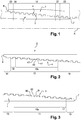
- the threaded tubular connection shown in Figure 1 comprises a tubular component provided with a male member 1 and a tubular component provided with a female member 2. Both male member 1 and female member 2 are provided with tapered threaded zones 3, 4 that cooperate for mutual connection by make-up of the two components. Figure 1 , the threaded connection is shown fully made up.
- the male member finishes in a male terminal surface 7, forming an axial free end of the male member or pin face.
- the male terminal surface 7 is also a free axial surface of the first tubular component.
- the female member 2 finishes in a female terminal surface 8, forming an axial free end of the female member or box face.
- the female terminal surface 8 is also a free axial surface of the second tubular component.
- the male terminal surface 7 and the female terminal surface 8 are oriented radially with respect to the longitudinal axis X of the connection. None of the male terminal surface 7 and the female terminal surface 8 are placed in abutment contact at the end of make up.
- both tubular component are integral, as they are both provided with a pipe body, a male member at one first distal end of the pipe body, and at an opposite distal end of the pipe body with a female member.
- Both tubular components are made out of steel. Threaded zones are respectively machined, wherein a surface treatment is provided to the female member only, and dope is additionally placed around the male member before make up.
- both the male member and the female member may be surface treated.
- a surface treatment may be Zinc Phosphate treatment.
- grade of the material is between 80 ksi (550 MPa) and 140 ksi (965 MPa).
- grade is above 100 ksi (690 MPa), for example 125 ksi (860 MPa).
- connection efficiency under both tension and compression are above 70 % of the pipe body yield strength.
- Pipe body may be with an outer diameter between 3 1 ⁇ 2" (88,90 mm) to 16" (406.4 mm), and pipe body wall width of 8 to 22 mm.
- the pipe body outer diameter may be 13 5/8" (330.2 mm), with a pipe body wall width of 0.625 “ (15.8 mm).
- Threaded zones may be single start. Each threaded zone may have a unique single threaded spire. A unique threaded spire means a spire with no interruption.
- connection of the invention is comprising a locking portion 10 wherein respective part of the threaded zones 3 and 4 are in a known "self-locking" configuration wherein both male threaded zone and female threaded zone present at least in that locking region 10 a progressive variation of the axial width of the thread crests and of the intervals between the threads such that a progressive axial tightening is produced during make-up until a final locking position.
- the term "self-locking" configuration means the characteristics detailed below for the teeth in the locking region.
- the male threads (or teeth) 32 like the female threads (or teeth) 42, have a constant lead although their crest width respectively decreases towards their respective terminal surface 7, 8 such that during make-up, some of male 32 and female 42 threads (or teeth) finish by locking into each other in a determined position. Thread in the locking configuration, are such that all the stab flanks and all the load flanks of the male threads (or teeth) lock against one another respectively the stab flanks and the load flanks of the corresponding female threads (or teeth).
- the locking region 10 At the end of makeup, in the locking region 10, there is no axial gap between axial flanks, both Load flanks and Stab flanks. Axial flanks define essentially radially compared to the axis of the connection. Moreover, design of the connection according to the invention is such that there is no radial gap between at least male thread crest and female thread root in the locking region. Thus, the locking region forms a seal by generating enough contact to trap dope and withstand high pressure. Crests and roots are in interfering contact, and axial flanks interfere too.
- only a specific number of threads of each of the male 32 and female 42 threads are in that specific locking configuration, and are involved in the locking portion 10.
- the locking portion 10 is away from the first and last thread of the threaded zone. At least first and last thread of both the male 32 and female 42 threads are not in a locking configuration.
- the male threaded zone 3 comprise a first portion 11 wherein the lead SFP_p between the male stabbing flanks 31 is constant at a value SFP_p1, and the lead LFP_p between the male load flanks 30 is also constant but at a different value LFP_p1.
- LFP_p1 is strictly superior to SFP_p1.
- the female threaded zone 4 comprise a second portion 12 wherein the lead LFP_b between the load flanks 41 is constant at a value LFP_b1, and the lead SFP_b between the stabbing flanks 40 is also constant but at a different value SFP_b1, with the feature that the lead between the load flanks 41 is greater than the lead between the stabbing flanks 40.
- the respective leads SFP_p1 and SFP_b1 between the male 31 and female 40 stabbing flanks are equal and smaller than the respective leads LFP_p1 and LFP_b1 between the male 30 and female 41 load flanks, which are themselves equal.
- the male threaded zone 3 comprises, in addition to the first portion 11, a male distal portion 13, adjacent to the first portion 11 and located on the side of the first portion closest to the male free end surface 7.
- the male threaded zone 3 also comprises a male proximal portion 15 adjacent to the first portion 11, but located on the other side of the first portion, the one farthest of the male free end surface 7.
- Each of the male distal portion 13 and the male proximal portion 15 comprise a portion of thread covering at least 360°, and preferably two turns.
- the male distal portion 13 and the male proximal portion 15 distinguish from the first portion 11, by the lead of at least one of the stab flank and/or the load flank is/are distinct from the values observed in the first portion.
- Male distal portion 13 and the male proximal portion 15 distinguish from the first portion 11 by only the lead of the stabbing flank SFP_p, the lead of the load flank LFP_p remaining at a same value LFP_p1 all along the threaded portion.
- lead of the male stabbing flanks in the distal portion 13 and the proximal portion 15 are equal and equal to the lead of the male load flanks LFP_p1.
- the lead of the male stabbing flank in the first portion 11 reach a value SFP_p1 inferior to the male load flank lead LFP_p1.
- a male wedge ratio along the male distal and proximal portions equals 0, whereas a non-null wedge ratio exists within the male first portion 11.
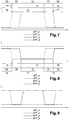
- Figure 7 proposes a strictly positive, non-null, wedge ratio in the first portion and null wedge ratio along the male distal and proximal portions obtained by the sole increase of the Load flanks lead in the first portion relative to both distal and proximal male portions.
- Load Flank lead equals Stab Flanks lead
- Stab Flank leads remaining constant all along the threaded portion.
- wedge ratio in the male distal and proximal portion is strictly above 0, non-null, and strictly below the wedge ratio observed along the first portion.
- the lead of the stab flank within the male distal and respectively proximal portion being lower to the lead of the load flanks in that male distal portion and respectively proximal portion, while the lead of the Load flank in the male distal portion remains constant and equals to the lead of the Load flanks in the first portion.
- Another embodiment according to the invention could cover a varying wedge ratio within the male distal and proximal portion, such varying value remaining strictly below the wedge ratio of the fist portion. Values of wedge ratio and/or pattern of variation of wedge ratio along the distal and proximal portion may be identical or not.
- the female threaded zone 4 comprises, in addition to the second portion 12, a female distal portion 14, adjacent to the second portion 12, located on the side of the second portion closest to the female free end surface 8.
- the female threaded zone 4 comprises a female proximal portion 16 adjacent to the second portion 12, but located on the other side of the second portion, the one farthest of the female free end surface 8.
- Each of the female distal portion 14 and the female proximal portion 16 comprises a portion of thread covering at least 360°, and preferably two turns.
- the female distal portion 14 and the female proximal portion 16 distinguish from the second portion 12, by the lead of at least one of the stab flank and/or the load flank is/are distinct from the values observed in the second portion.
- female distal portion 14 and the female proximal portion 16 distinguish from the second portion 12, by only the lead of the stabbing flank SFL_b, the lead of the load flank LFP_b remaining at a same value LFP_b1 all along the threaded portion.
- lead of the female stabbing flanks in the distal portion 14 and the proximal portion 16 are equal and equal to the lead of the female load flanks LFP_b1, which is also equal to the male Load Flanks LFP_p1.
- the lead of the female stabbing flanks in the second portion 12 reach a value SFP_b1 inferior to the male load flank lead LFP_b1.
- female distal and proximal portions present the same type of variation of the Stab flanks lead and Load flanks lead as is the case in the male treaded portion, except that the location of changes in the female leads are not superimposed along a longitudinal axis of the connection, with the location of those changes in the male leads.
- a tooth engaged in an interval is to be interpreted as at least a 360 ° tooth engaged in at least a 360° interval, In the transition region 20 and 21, there is no contact between at least one of the stabbing flanks and/or the load flanks.
- Locking parts 10p and 10b are locking threads defining the locking region.
- Figures 1 to 3 are a representation of the "and” option.
- Transition region 20 is where female remainder part 18 of the second portion 12 engage the male proximal portion 15.
- Transition region 21 is where male remainder part 17 of the first portion 11 engage the female proximal portion 16.
- the first portion 11 is consisting of a male locking part 10p and a remainder part 17.
- the second portion 12 is consisting of a female locking part 10b and a remainder part 18.
- the threaded connection from the transition region 21 to the male free end 7, the threaded connection comprises an internal threaded region 23, where the male distal portion 13 engages the female proximal portion 16.
- the threaded connection comprises an external threaded region 22, where the male proximal portion 15 engages the female distal portion 14.
- a positive clearance exists between respective male and female stab flanks. For example, that clearance is at least 1 mm, and for example below 5 mm.
- the locking region 10 locates axially in the middle of the threaded connection.
- part 10p of the first portion 11 locates axially in the middle of the male threaded zone 3
- part 10b of the second portion 12 locates axially in the middle of the female threaded zone 4.
- the locking region comprises 8 threads where the threaded connection in full comprises at least 10 threads, and preferably more than 14 threads, for example 16 threads.
- n number of threads of the locking region
- the number of threads of the connection is for example at least more than 1,25 times ⁇ n; and more preferably at least more than 1,75 ⁇ n; for example 2 times ⁇ n.
- Variation of the male stab flank lead SFP_p curve between proximal portion 15 and first portion 11 is located at 515 and respectively reversely at 516 between first portion 11 and male distal portion 13.
- Variation 513 and 514 are sudden, and appear in less than one turn, preferably less than 180°.
- Variation of the female stab flank lead SFP_b curve between proximal portion 16 and second portion 12 is located at 513 and respectively reversely at 514 between second portion 12 and female distal portion 14.
- Variation 514 and 513 are sudden, and appear in less than one turn, preferably less than 180°.
- transition region 20 defines between variations 514 and 515.
- Symmetrically variations 513 and 516 occurring at a different axial location within the threaded connection the transition region 21 defines between variations 513 and 516.
- Transition region 20 and 21 in accordance with the invention enables to conserve a good effective locking portion despite variations in the axial positioning of the assembled elements due to machining tolerances, the effective seal of the locking region being efficient over several teeth of that locking portion.
- both male and female thread have the same load flank lead and stab flank lead.
- male teeth involved in the internal thread portion 23 have all the same constant crest width CWTpmin as the female teeth involved in the external thread portion 22, which have the same crest width CWTbmin.
- the internal thread portion 23 comprises the teeth of the male distal portion closest to the male terminal surface 7, which are the teeth with the smallest crest width value of the whole male threaded zone 3.
- the inventors in order to avoid early thread crest interference, during make up, the inventors have discover the need to control by a relation between the teeth crest width and the box rear non-locking thread gap width.
- the male and female threads have a dovetail profile.
- This profile enables to avoid the risk of jump-out, which corresponds to the male and female threads coming apart when the connection is subjected to large bending or tensile stresses.
- the geometry of the dovetail threads increases the radial rigidity of their assembly compared with threads, which are usually termed "trapezoidal" threads wherein the axial teeth width reduces from the base to the crest of the threads.
- the load flanks of the thread connect to the thread crest and to the adjacent thread root by roundings such that these roundings reduce the stress concentration factor at the foot of the load flanks and thereby improve the fatigue behavior of the connection.
- both load flank and stab flank present a straight profile.
- Load flank and stab flank are respectively making an angle ⁇ with a vertical to the longitudinal axis X.
- Load flank angle value equals stab flank angle value, while being opposed and defined on opposed sides of a vertical to the longitudinal axis X.
- angle ⁇ is comprised between 1° and 6°, for example equals 5°.
- the threaded connection is tapered so as to facilitate the progress of make-up.
- a pitch line is having a taper angle 0 ⁇ with the longitudinal axis X.
- the pitch line defines as passing through the aligned center of the flanks of the male threaded zone having a same lead value all along the connection.
- the lead of the load flanks remains at a same value all along the male threaded zone, thus the pin pitch line defines as passing through the aligned center of the load flanks.
- the taper angle 0 ⁇ is for example comprised between 1 and 10°, for example equals 4,7°.
- BTG SFP _ p 1 2 ⁇ n 2 ⁇ LFP p 1 ⁇ SFP p 1
- BTG is also the female minimum thread gap of thread teeth not involved in the locking region, for example of thread gap of the female proximal portion 16.
- the crest width of a tooth, or largest width dimension of that tooth, is such that the minimum value (CWTpmin) of the width of the crest of the tooth which is closest to the male terminal surface 7 fulfill at least one of, and preferably both of the below equations
- Figure 7 is an alternative embodiment of Figure 6 , wherein difference with Figure 6 mainly explain as differential variation of the load flank lead and stab flank lead. According to a second embodiment of the invention, Figure 7 ,
- Figure 8 is another alternative embodiment of Figure 6 , wherein difference with Figure 6 mainly explain as the load flank lead of the female and male member in their respective distal portion and proximal portion is greater than the value of both the male and female load flank lead. Load flank lead is constant all over the connection, respectively equals to LFP_p1.
- Figure 9 is combining male leads change as of Figure 6 together with female leads change as of Figure 7 , with the constant feature of the axial location of the male and female leads changes being not superimposed.
- the invention encompass threaded connection comprising a locking portion, adjacent to a transition portion, the transition portion being adjacent to a distal or proximal portion, such that teeth are not in self-locking engagement in both the transition portion and at least one of the distal and proximal portion.
- teeth not in self-locking arrangement are such that stab flanks are not interfering, and male or female tooth having the same minimal crest width.
- the invention encompass threaded connection comprising a locking portion being adjacent at both axial ends of the locking portion to transition portions, such that teeth are not in self-locking engagement in both transition portions.
- the minimum make-up torque required may be between 55 000 ft.lbs (74570 N.m) and 70 000 ft.lbs (94 907 N.m).
Landscapes
- Engineering & Computer Science (AREA)
- Geology (AREA)
- Life Sciences & Earth Sciences (AREA)
- Mining & Mineral Resources (AREA)
- Mechanical Engineering (AREA)
- General Life Sciences & Earth Sciences (AREA)
- Fluid Mechanics (AREA)
- Environmental & Geological Engineering (AREA)
- Physics & Mathematics (AREA)
- Geochemistry & Mineralogy (AREA)
- General Engineering & Computer Science (AREA)
- Non-Disconnectible Joints And Screw-Threaded Joints (AREA)
- Mutual Connection Of Rods And Tubes (AREA)
- Earth Drilling (AREA)
- Reinforcement Elements For Buildings (AREA)
- Flexible Shafts (AREA)
- Infusion, Injection, And Reservoir Apparatuses (AREA)
Claims (25)
- Eine Gewindeverbindung, die eine erste und eine zweite rohrförmige Komponente umfasst, wobei die erste rohrförmige Komponente über einen Rohrkörper und ein Außenelement (1) an einem entfernten Endstück des Rohrkörpers verfügt, die zweite rohrförmige Komponente über einen weiteren Rohrkörper und ein Innenelement (2) an einem entfernten Ende dieses Rohrkörpers verfügt, so dass ein Außenelement (1) an seiner Außenumfangsfläche mindestens einen Außengewindebereich (3) umfasst und in einer Außenendfläche (7) endet und ein Innenelement (2) auf der Innenumfangsfläche mindestens einen Innengewindebereich (4) umfasst und in einer Innenendfläche (8) endet,
wobei der Außengewindebereich (3) ein Außengewinde umfasst, das einen ersten Abschnitt aufweist, in dem die Breite der Gewindespitze (CWTp) in eine Richtung von der Außenendfläche zum Rohrkörper der ersten rohrförmigen Komponente zunimmt und der Zahn, welcher der Außenendfläche (7) am nächsten ist, einen Mindestwert der Spitzenbreite (CWTpmin) des Außengewindes aufweist und
der Innengewindebereich (4) ein Innengewinde aufweist, welches einen zweiten Abschnitt aufweist, in dem die Breite der Gewindespitze (CWTb) in einer Richtung von der Innenendfläche zum Rohrkörper der zweiten rohrförmigen Komponente zunimmt, wobei der Zahn, welcher der Innenendfläche (8) am nächsten ist, einen Mindestwert der Spitzenbreite (CWTbmin) des Innengewindes aufweist
wobei jeder Zahn des ersten Abschnitts sich zwischen zwei angrenzenden Zähnen des zweiten Abschnitts befindet, wenn die Verbindung verschraubt wird und dadurch charakterisiert wird, dass nur
ein Teil des ersten Abschnitts mit nur einem Teil des zweiten Abschnitts entsprechend einer selbstsperrenden Verschraubung zusammenarbeitet, um einen Verriegelungsbereich in der Gewindeverbindung herzustellen. - Gewindeverbindung gemäß Anspruch 1, in welcher der Verriegelungsbereich eine Anzahl (n) Gewindegänge in selbstsperrender Anordnung umfasst, wobei der erste und zweite Abschnitt eine Anzahl Gewindegänge umfasst, welche größer ist, als die Anzahl (n) Gewindegänge des Verriegelungsbereichs.
- Gewindeverbindung gemäß einem der vorstehenden Ansprüche, wobei der Außengewindebereich einen entfernten Außenabschnitt aufweist, der durch ein Keilverhältnis definiert wird, welches sich von dem im Verriegelungsbereich unterscheidet, wobei der entfernte Abschnitt den Zahn umfasst, welcher der Außenendfläche (7) am nächsten ist und der entfernte Außenabschnitt an den ersten Abschnitt grenzt.
- Gewindeverbindung gemäß einem der vorstehenden Ansprüche, wobei der Innengewindebereich einen entfernten Innenabschnitt aufweist, welcher durch ein Keilverhältnis definiert wird, das sich von dem im Verriegelungsbereich unterscheidet, wobei der entfernte Innenabschnitt den Zahn umfasst, welcher der Innenendfläche (8) am nächsten ist und der entfernte Innenabschnitt an den zweiten Abschnitt grenzt.
- Gewindeverbindung gemäß einem der vorstehenden Ansprüche, wobei der Zahn des entfernten Innenabschnitts, welcher der Innenendfläche am nächsten ist, die gleiche Spitzenbreite wie der Zahn des entfernten Außenabschnitts aufweist, welcher der Außenendfläche am nächsten ist (CWTbmin = CWTpmin).
- Gewindeverbindung gemäß einem der vorstehenden Ansprüche, in der die Steigung der Außeneingriffsflanken (SFP_p) im ersten Abschnitt konstant ist und in einem entfernten Abschnitt des Außengewindebereichs einen bestimmten Wert erhält, wobei dieser bestimmte Wert kleiner oder gleich dem Wert der Steigung der Außenlastflanken (LFP_p) ist, der in den ersten und entfernten Abschnitten konstant bleibt, wobei der entfernte Außenabschnitt an den ersten Abschnitt grenzt.
- Gewindeverbindung gemäß einem der Ansprüche 1 bis 5, in der die Steigung der Außenlastflanken (LFP_p) im ersten Abschnitt konstant ist und in einem entfernten Abschnitt des Außengewindebereiches einen bestimmten Wert erhält, wobei dieser Wert größer oder gleich dem Wert der Steigung der Außeneingriffsflanken (SFP_p) ist, der in den ersten und entfernten Abschnitten konstant bleibt, wobei der entfernte Außenabschnitt an den ersten Abschnitt grenzt.
- Gewindeverbindung gemäß einem der vorstehenden Ansprüche, in welcher der Außengewindebereich einen nahen Außenabschnitt aufweist, der durch ein Keilverhältnis definiert wird, welches sich von dem im Verriegelungsbereich unterscheidet, wobei der nahe Abschnitt den Zahn umfasst, welcher von der Außenendfläche am weitesten entfernt ist und der nahe Außenabschnitt an den ersten Abschnitt grenzt.
- Gewindeverbindung gemäß einem der vorstehenden Ansprüche, in welcher der Innengewindebereich einen nahen Innenabschnitt aufweist, welcher durch ein Keilverhältnis definiert wird, das sich von dem im Verriegelungsbereich unterscheidet, wobei der nahe Abschnitt den Zahn umfasst, welcher von der Innenendfläche am weitesten entfernt ist und der nahe Innenabschnitt an den zweiten Abschnitt grenzt.
- Gewindeverbindung gemäß einem der vorstehenden Ansprüche, in der die Steigung der Außeneingriffsflanken (SFP_p) im ersten Abschnitt konstant ist und in einem nahen Abschnitt des Außengewindebereichs einen bestimmten Wert erhält, welcher kleiner oder gleich dem Wert der Steigung der Außenlastflanken (LFP_p) ist, der in den ersten und nahen Abschnitten konstant bleibt, wobei der nahe Außenabschnitt an den ersten Abschnitt grenzt.
- Gewindeverbindung gemäß einem der Ansprüche 1 bis 9, in der die Steigung der Außenlastflanken (LFP_p) im ersten Abschnitt konstant ist und in einem nahen Abschnitt des Außengewindebereiches einen Wert größer oder gleich dem Wert der Steigung der Außeneingriffsflanken (SFP_p) erhält, der in den ersten und nahen Abschnitten konstant bleibt, wobei der nahe Außenabschnitt an den ersten Abschnitt grenzt.
- Gewindeverbindung gemäß einem der vorstehenden Ansprüche, in der das Keilverhältnis sich an zwei Stellen in sowohl dem Außengewindebereich, als auch dem Innengewindebereich ändert.
- Gewindeverbindung gemäß einem der vorstehenden Ansprüche, in der die Steigung der Außeneingriffsflächen sich an zwei Stellen des Außengewindebereichs ändert und die Inneneingriffsflächen sich an zwei Stellen des Innengewindebereichs ändern und die Steigung der Außenlastflanken und die Steigung der Innenlastflanken entlang des gesamten Außengewindebereichs und entsprechend des Innengewindebereichs konstant bleibt.
- Gewindeverbindung gemäß einem der vorstehenden Ansprüche, in welcher der Außengewindebereich ein Schwalbenschwanzgewinde umfasst und der Mindestwert (CWTpmin) der Breite des Zahns, welcher der Außenendfläche am nächsten ist, mindestens einer der nachstehenden Gleichungen entspricht(a)
 (b)
(b)
 n der Anzahl sperrender Gewindegänge des Verriegelungsbereichs entsprichtSFP_p1 der Steigung der Eingriffsflanke im ersten Abschnitt entsprichtLFP_p1 der Steigung der Lastflanke im ersten Abschnitt entspricht
LFPp1 - SFPp1 auch Keilverhältnis genannt wirdTH einer Nenn-Gewindehöhe im ersten Abschnitt entsprichtPLH dem Abstand von der Flankendurchmesserlinie des Bolzens zum Grund im ersten Abschnitt entspricht.Die Flankendurchmesserlinie des Bolzens wird durch alle Punkte auf halber Höhe der Flanken bestimmt, wobei diese Flanken in diesem ersten Abschnitt eine konstante Steigung aufweisen.α ist der Last- und entsprechend Eingriffsflankenwinkel einer Senkrechten zur Achse der Verbindungφ entspricht dem Kegelwinkel, wobei der Kegelwinkel einem Winkel zwischen einer Mantellinie von Außen- und Innengewindebereichen und der Achse der Verbindung entspricht - Gewindeverbindung gemäß einem der vorstehenden Ansprüche, in der die Außengewindebereiche und Innengewindebereiche (3, 4) eine konische Mantellinie aufweisen, welche mit der Achse (10) der Verbindung einen Winkel im Bereich von 1 Grad bis 5 Grad bildet.
- Gewindeverbindung gemäß einem der vorstehenden Ansprüche, in der die Zähne der Außen- und Innengewindebereiche (3, 4) ein Schwalbenschwanzprofil aufweisen und die Spitzen der Zähne und die Gründe der Außen- und Innengewindebereiche (3, 4) parallel zur Achse (10) der Gewindeverbindung laufen.
- Gewindeverbindung gemäß vorstehendem Anspruch, in der die Zähne der Außen- und Innengewindebereiche (3, 4) ein derartiges Schwalbenschwanzprofil aufweisen, dass die Lastflanken bzw. Eingriffsflanken in einem Winkel mit dem gleichen Winkelwert a im Verhältnis zu einer Senkrechten zu einer Achse der Verbindung stehen, wobei dieser Winkel a zwischen 1° und 6° beträgt.
- Gewindeverbindung gemäß einem der vorstehendem Ansprüche, in der nur eine Spitze der Zähne des Außengewindebereichs mit den Gründen des Innengewindebereichs (4) oder die Gründe der Zähne des Außengewindebereichs mit den Spitzen des Innengewindebereichs im Verriegelungsbereich eingreifen, so dass der Eingriffsdurchmesser am Eingriff Grund/Spitze mehr als das 0,0025-fache des Nennaußendurchmessers des Rohrkörpers betragen kann.
- Gewindeverbindung gemäß einem der vorstehenden Ansprüche, in der diese frei von einer entfernten Stoßfläche ist, ein freies Endstück des Außenelements entfernt von dem Innenelement ist und entsprechend ein freies Ende des Innenelements von dem Außenelement entfernt ist.
- Gewindeverbindung gemäß einem der vorstehenden Ansprüche, in der sowohl das Außen-, als auch das Innenelement abgesehen von dem Verriegelungsbereich frei von zusätzlichen Dichtflächen sind.
- Gewindeverbindung gemäß einem der vorstehenden Ansprüche, in der die Gewindeverbindung halb-fluchtend ist und die erste und eine zweite rohrförmige Komponente integral sind, wobei jede erste und zweite rohrförmige Komponente ein Außenelement und ein Innenelement umfassen.
- Gewindeverbindung gemäß einem der vorstehenden Ansprüche, in der das Teil des ersten Abschnitts und entsprechend das Teil des zweiten Abschnitts des Gewindebereichs des Außen-, bzw. Innenelements selbstsperrend im Verriegelungsbereich zusammenarbeiten, wobei jedes mehr als 30 % und weniger als 80 % und vorzugsweise mehr als 50 % der Anzahl Zähne des jeweiligen Gewindebereichs darstellt.
- Gewindeverbindung gemäß einem der vorstehenden Ansprüche, in der alle Zähne des Außen- und/oder Innengewindebereichs die gleiche Höhe aufweisen, mit Ausnahme des Zahns, der eine Mindestspitzenbreite aufweist.
- Gewindeverbindung gemäß einem der vorstehenden Ansprüche, in welcher der Außengewindebereich und der Innengewindebereich jeweils einen eingängigen durchgehenden Gewindegang darstellen.
- Gewindeverbindung gemäß einem der vorstehenden Ansprüche, in welcher der Außengewindebereich und der Innengewindebereich jeweils eingängige Gewinde darstellen.
Priority Applications (10)
| Application Number | Priority Date | Filing Date | Title |
|---|---|---|---|
| EP17306444.5A EP3473798B1 (de) | 2017-10-20 | 2017-10-20 | Gewindeverbindung, teilweise in einem selbsthemmenden eingriff |
| CN201880067724.4A CN111566309B (zh) | 2017-10-20 | 2018-10-02 | 部分地处于自锁接合的螺纹连接装置 |
| JP2020521975A JP7186221B2 (ja) | 2017-10-20 | 2018-10-02 | 部分的に自動ロック式に係合するねじ接続部 |
| PCT/EP2018/076734 WO2019076622A1 (en) | 2017-10-20 | 2018-10-02 | PARTIALLY THREADED CONNECTION IN SELF-LOCKING OUTLET |
| MX2020004061A MX2020004061A (es) | 2017-10-20 | 2018-10-02 | Conexion en rosca parcialmente en un acoplamiento autoblocante. |
| BR112020005689-8A BR112020005689B1 (pt) | 2017-10-20 | 2018-10-02 | Conexão roscada parcialmente em um engate de travamento automático |
| US16/754,031 US11840895B2 (en) | 2017-10-20 | 2018-10-02 | Threaded connection partially in a self-locking engagement |
| CA3078838A CA3078838A1 (en) | 2017-10-20 | 2018-10-02 | Threaded connection partially in a self-locking engagement |
| EA202090667A EA039821B1 (ru) | 2017-10-20 | 2018-10-02 | Резьбовое соединение, находящееся частично в самоблокирующемся зацеплении |
| ARP180103074A AR113396A1 (es) | 2017-10-20 | 2018-10-19 | Conexión en rosca parcialmente en un acoplamiento autoblocante |
Applications Claiming Priority (1)
| Application Number | Priority Date | Filing Date | Title |
|---|---|---|---|
| EP17306444.5A EP3473798B1 (de) | 2017-10-20 | 2017-10-20 | Gewindeverbindung, teilweise in einem selbsthemmenden eingriff |
Publications (2)
| Publication Number | Publication Date |
|---|---|
| EP3473798A1 EP3473798A1 (de) | 2019-04-24 |
| EP3473798B1 true EP3473798B1 (de) | 2020-03-11 |
Family
ID=60201482
Family Applications (1)
| Application Number | Title | Priority Date | Filing Date |
|---|---|---|---|
| EP17306444.5A Active EP3473798B1 (de) | 2017-10-20 | 2017-10-20 | Gewindeverbindung, teilweise in einem selbsthemmenden eingriff |
Country Status (10)
| Country | Link |
|---|---|
| US (1) | US11840895B2 (de) |
| EP (1) | EP3473798B1 (de) |
| JP (1) | JP7186221B2 (de) |
| CN (1) | CN111566309B (de) |
| AR (1) | AR113396A1 (de) |
| BR (1) | BR112020005689B1 (de) |
| CA (1) | CA3078838A1 (de) |
| EA (1) | EA039821B1 (de) |
| MX (1) | MX2020004061A (de) |
| WO (1) | WO2019076622A1 (de) |
Families Citing this family (11)
| Publication number | Priority date | Publication date | Assignee | Title |
|---|---|---|---|---|
| JP7189961B2 (ja) * | 2018-10-11 | 2022-12-14 | 日本製鉄株式会社 | 鋼管用ねじ継手 |
| CA3115198C (en) * | 2018-10-11 | 2023-06-13 | Nippon Steel Corporation | Threaded connection for steel pipe |
| FR3098879B1 (fr) * | 2019-07-19 | 2021-07-30 | Vallourec Oil & Gas France | Joint fileté à profil hélicoïdal dissymétrique |
| CA3144702C (en) * | 2019-09-02 | 2024-04-30 | Nippon Steel Corporation | Threaded connection for steel pipe |
| EP3835541A1 (de) * | 2019-12-13 | 2021-06-16 | Vallourec Oil And Gas France | Gewindeverbindung, teilweise in einem selbstsichernden eingriff mit einer äusseren schulter, die einem erhöhten drehmoment standhalten kann |
| EP3854987B1 (de) | 2020-01-27 | 2023-08-02 | Vallourec Oil And Gas France | Selbstsichernde gewindeverbindung, teilweise in nicht sicherndem eingriff |
| JP7352738B2 (ja) * | 2020-06-26 | 2023-09-28 | 日本製鉄株式会社 | 鋼管用ねじ継手 |
| EP3940193B1 (de) * | 2020-07-13 | 2023-03-08 | Tenaris Connections B.V. | Gewindeverbindung |
| EP3992418B1 (de) | 2020-10-28 | 2023-08-02 | Vallourec Oil And Gas France | Selbstsichernde gewindeverbindung, teilweise in nicht sicherndem eingriff |
| CN116583655A (zh) * | 2020-11-23 | 2023-08-11 | 美国钢铁公司 | 具有提高的密封性的螺纹管连接件 |
| EP4102025B1 (de) | 2021-06-07 | 2023-06-07 | Vallourec Oil And Gas France | Selbstsichernde gewindeverbindung, teilweise in nicht sicherndem eingriff |
Citations (18)
| Publication number | Priority date | Publication date | Assignee | Title |
|---|---|---|---|---|
| US5338074A (en) | 1989-03-02 | 1994-08-16 | The Hydril Company | Threaded pipe connection |
| DE4345119C1 (de) | 1993-12-30 | 1995-05-11 | Mannesmann Ag | Rohrverbinder |
| US6158785A (en) | 1998-08-06 | 2000-12-12 | Hydril Company | Multi-start wedge thread for tubular connection |
| US6206436B1 (en) | 1999-02-19 | 2001-03-27 | Hydril Company | Differential wedge thread for threaded connector |
| US20060145477A1 (en) | 2004-12-30 | 2006-07-06 | Reynolds Harris A Jr | Threads with perturbations |
| US20060145480A1 (en) | 2004-12-30 | 2006-07-06 | Hydril Company | Floating wedge thread for tubular connection |
| US20060261595A1 (en) | 2003-05-30 | 2006-11-23 | Vallourec Mannesmann Oil & Gas France | Threaded tubular connection with progressive axial thread interference |
| WO2007149673A1 (en) | 2006-06-16 | 2007-12-27 | Hydril Company | Wedge thread with high-metal seal |
| US20080054633A1 (en) | 2006-08-29 | 2008-03-06 | Reynolds Harris A | Scalloped wedge threads |
| WO2008116891A1 (en) | 2007-03-28 | 2008-10-02 | Tenaris Connections Ag | Super high torque dope-free threaded joint |
| US7475917B2 (en) | 2006-03-30 | 2009-01-13 | Hydril Company | Threaded connection with variable flank angles |
| US7850211B2 (en) | 2006-01-24 | 2010-12-14 | Hydril Company | Wedge thread connections having a clearance gap volume |
| WO2011060894A2 (en) | 2009-11-20 | 2011-05-26 | Vallourec Mannesmann Oil & Gas France | Threaded connection |
| US20110278838A1 (en) | 2008-12-16 | 2011-11-17 | Sumitomo Metal Industries, Ltd. | Tubular connection with self-locking threading used in the oil industry |
| US20140203556A1 (en) | 2011-09-13 | 2014-07-24 | Vallourec Oil And Gas France | Assembly for producing a threaded joint for the drilling and operation of hydrocarbon wells, and resulting threaded joint |
| US20160186899A1 (en) | 2011-08-05 | 2016-06-30 | Vallourec Oil And Gas France | Tubular connection with self-locking thread form used in the oil industry |
| US20160208962A1 (en) | 2013-09-06 | 2016-07-21 | Nippon Steel & Sumitomo Metal Corporation | Threaded connection for steel pipe |
| WO2017024208A1 (en) | 2015-08-05 | 2017-02-09 | Hydril Company | Threaded tubular connection |
Family Cites Families (18)
| Publication number | Priority date | Publication date | Assignee | Title |
|---|---|---|---|---|
| USRE30647E (en) | 1975-04-23 | 1981-06-16 | Hydril Company | Tubular connection |
| USRE34467E (en) | 1983-04-29 | 1993-12-07 | The Hydril Company | Tubular connection |
| GB8323348D0 (en) * | 1983-08-31 | 1983-10-05 | Hunting Oilfield Services Ltd | Pipe connectors |
| US4600224A (en) * | 1983-12-23 | 1986-07-15 | Interlock Technologies Corporation | Tubular connection having a chevron wedge thread |
| EP1046779A1 (de) * | 1999-04-19 | 2000-10-25 | Hydril Company | Beschraubte Rohrverbindung |
| US6530607B1 (en) * | 2000-11-06 | 2003-03-11 | Hydril Company | Two-step threaded connector having differential thread width |
| US20040251686A1 (en) * | 2003-06-10 | 2004-12-16 | Otten Gregory K. | Multi-taper and multi-pitch diameter API eight round thread coupling |
| FR2945604B1 (fr) * | 2009-05-12 | 2011-06-03 | Vallourec Mannesmann Oil & Gas | Ensemble pour la realisation d'un joint filete pour le forage et l'exploitation des puits d'hydrocarbures et joint filete resultant |
| US20120074693A1 (en) * | 2010-09-24 | 2012-03-29 | Hydril Company | Step-to-step wedge thread connections and related methods |
| WO2016108141A1 (en) | 2014-12-31 | 2016-07-07 | Vallourec Oil And Gas France | Tubular connection with self-locking thread form used in the oil industry |
| US8931809B2 (en) * | 2012-09-21 | 2015-01-13 | Vallourec Oil And Gas France | Tubular threaded connection |
| CN103061685B (zh) * | 2013-01-08 | 2017-02-08 | 深圳市阿特拉能源技术有限公司 | 井底钻进工具及其防脱落自锁紧结构 |
| FR3006029B1 (fr) | 2013-05-23 | 2015-11-13 | Vallourec Mannesmann Oil & Gas | Ensemble pour la realisation d'un joint filete pour le forage et l'exploitation des puits d'hydrocarbures et joint filete resultant |
| FR3030668B1 (fr) * | 2014-12-19 | 2016-12-16 | Vallourec Oil & Gas France | Joint filete |
| JP6654643B2 (ja) | 2015-10-21 | 2020-02-26 | 日本製鉄株式会社 | 鋼管用ねじ継手 |
| CN105422448B (zh) * | 2016-01-05 | 2017-05-31 | 中国石油大学(华东) | 一种变齿宽变螺距的螺杆转子 |
| CN205558826U (zh) * | 2016-03-31 | 2016-09-07 | 西安钧力石油装备制造有限公司 | 一种变齿宽楔形管螺纹连接结构 |
| JP7189961B2 (ja) * | 2018-10-11 | 2022-12-14 | 日本製鉄株式会社 | 鋼管用ねじ継手 |
-
2017
- 2017-10-20 EP EP17306444.5A patent/EP3473798B1/de active Active
-
2018
- 2018-10-02 BR BR112020005689-8A patent/BR112020005689B1/pt active IP Right Grant
- 2018-10-02 EA EA202090667A patent/EA039821B1/ru unknown
- 2018-10-02 CA CA3078838A patent/CA3078838A1/en active Pending
- 2018-10-02 US US16/754,031 patent/US11840895B2/en active Active
- 2018-10-02 MX MX2020004061A patent/MX2020004061A/es unknown
- 2018-10-02 JP JP2020521975A patent/JP7186221B2/ja active Active
- 2018-10-02 WO PCT/EP2018/076734 patent/WO2019076622A1/en active Application Filing
- 2018-10-02 CN CN201880067724.4A patent/CN111566309B/zh active Active
- 2018-10-19 AR ARP180103074A patent/AR113396A1/es active IP Right Grant
Patent Citations (19)
| Publication number | Priority date | Publication date | Assignee | Title |
|---|---|---|---|---|
| US5338074A (en) | 1989-03-02 | 1994-08-16 | The Hydril Company | Threaded pipe connection |
| DE4345119C1 (de) | 1993-12-30 | 1995-05-11 | Mannesmann Ag | Rohrverbinder |
| US6158785A (en) | 1998-08-06 | 2000-12-12 | Hydril Company | Multi-start wedge thread for tubular connection |
| US6206436B1 (en) | 1999-02-19 | 2001-03-27 | Hydril Company | Differential wedge thread for threaded connector |
| US20060261595A1 (en) | 2003-05-30 | 2006-11-23 | Vallourec Mannesmann Oil & Gas France | Threaded tubular connection with progressive axial thread interference |
| US7828337B2 (en) | 2004-12-30 | 2010-11-09 | Hydril Company Lp | Threaded connection with wedge segments |
| US20060145477A1 (en) | 2004-12-30 | 2006-07-06 | Reynolds Harris A Jr | Threads with perturbations |
| US20060145480A1 (en) | 2004-12-30 | 2006-07-06 | Hydril Company | Floating wedge thread for tubular connection |
| US7850211B2 (en) | 2006-01-24 | 2010-12-14 | Hydril Company | Wedge thread connections having a clearance gap volume |
| US7475917B2 (en) | 2006-03-30 | 2009-01-13 | Hydril Company | Threaded connection with variable flank angles |
| WO2007149673A1 (en) | 2006-06-16 | 2007-12-27 | Hydril Company | Wedge thread with high-metal seal |
| US20080054633A1 (en) | 2006-08-29 | 2008-03-06 | Reynolds Harris A | Scalloped wedge threads |
| WO2008116891A1 (en) | 2007-03-28 | 2008-10-02 | Tenaris Connections Ag | Super high torque dope-free threaded joint |
| US20110278838A1 (en) | 2008-12-16 | 2011-11-17 | Sumitomo Metal Industries, Ltd. | Tubular connection with self-locking threading used in the oil industry |
| WO2011060894A2 (en) | 2009-11-20 | 2011-05-26 | Vallourec Mannesmann Oil & Gas France | Threaded connection |
| US20160186899A1 (en) | 2011-08-05 | 2016-06-30 | Vallourec Oil And Gas France | Tubular connection with self-locking thread form used in the oil industry |
| US20140203556A1 (en) | 2011-09-13 | 2014-07-24 | Vallourec Oil And Gas France | Assembly for producing a threaded joint for the drilling and operation of hydrocarbon wells, and resulting threaded joint |
| US20160208962A1 (en) | 2013-09-06 | 2016-07-21 | Nippon Steel & Sumitomo Metal Corporation | Threaded connection for steel pipe |
| WO2017024208A1 (en) | 2015-08-05 | 2017-02-09 | Hydril Company | Threaded tubular connection |
Also Published As
| Publication number | Publication date |
|---|---|
| EA039821B1 (ru) | 2022-03-17 |
| JP2020537723A (ja) | 2020-12-24 |
| US20200325734A1 (en) | 2020-10-15 |
| US11840895B2 (en) | 2023-12-12 |
| BR112020005689B1 (pt) | 2022-02-22 |
| JP7186221B2 (ja) | 2022-12-08 |
| CA3078838A1 (en) | 2019-04-25 |
| AR113396A1 (es) | 2020-04-29 |
| CN111566309B (zh) | 2022-05-24 |
| EP3473798A1 (de) | 2019-04-24 |
| EA202090667A1 (ru) | 2020-07-31 |
| WO2019076622A1 (en) | 2019-04-25 |
| BR112020005689A2 (pt) | 2020-10-20 |
| MX2020004061A (es) | 2020-07-21 |
| CN111566309A (zh) | 2020-08-21 |
Similar Documents
| Publication | Publication Date | Title |
|---|---|---|
| EP3473798B1 (de) | Gewindeverbindung, teilweise in einem selbsthemmenden eingriff | |
| AU2010246716B2 (en) | Set for producing a threaded connection for drilling and operating hydrocarbon wells, and resulting threaded connection | |
| US10415322B2 (en) | Assembly for producing a threaded joint for the drilling and operation of hydrocarbon wells, and resulting threaded joint | |
| EP2366075B1 (de) | In der ölindustrie verwendete rohrverbindung mit selbstverriegelndem gewinde | |
| US7513534B2 (en) | Fatigue-resistant threaded component for a tubular threaded joint | |
| CA3197012C (en) | Self-locking threaded connection partially in non-locking engagement | |
| US10119637B2 (en) | Assembly for producing a threaded connection for drilling and operating hydrocarbon wells, and resulting threaded connection | |
| EP3854987B1 (de) | Selbstsichernde gewindeverbindung, teilweise in nicht sicherndem eingriff | |
| EP4102025B1 (de) | Selbstsichernde gewindeverbindung, teilweise in nicht sicherndem eingriff | |
| OA20773A (en) | Self-locking threaded connection partially in non-locking engagement. |
Legal Events
| Date | Code | Title | Description |
|---|---|---|---|
| PUAI | Public reference made under article 153(3) epc to a published international application that has entered the european phase |
Free format text: ORIGINAL CODE: 0009012 |
|
| STAA | Information on the status of an ep patent application or granted ep patent |
Free format text: STATUS: THE APPLICATION HAS BEEN PUBLISHED |
|
| AK | Designated contracting states |
Kind code of ref document: A1 Designated state(s): AL AT BE BG CH CY CZ DE DK EE ES FI FR GB GR HR HU IE IS IT LI LT LU LV MC MK MT NL NO PL PT RO RS SE SI SK SM TR |
|
| AX | Request for extension of the european patent |
Extension state: BA ME |
|
| RAP1 | Party data changed (applicant data changed or rights of an application transferred) |
Owner name: NIPPON STEEL CORPORATION Owner name: VALLOUREC OIL AND GAS FRANCE |
|
| STAA | Information on the status of an ep patent application or granted ep patent |
Free format text: STATUS: REQUEST FOR EXAMINATION WAS MADE |
|
| 17P | Request for examination filed |
Effective date: 20190826 |
|
| RIC1 | Information provided on ipc code assigned before grant |
Ipc: E21B 17/042 20060101AFI20191114BHEP |
|
| GRAP | Despatch of communication of intention to grant a patent |
Free format text: ORIGINAL CODE: EPIDOSNIGR1 |
|
| STAA | Information on the status of an ep patent application or granted ep patent |
Free format text: STATUS: GRANT OF PATENT IS INTENDED |
|
| INTG | Intention to grant announced |
Effective date: 20200109 |
|
| GRAS | Grant fee paid |
Free format text: ORIGINAL CODE: EPIDOSNIGR3 |
|
| GRAA | (expected) grant |
Free format text: ORIGINAL CODE: 0009210 |
|
| STAA | Information on the status of an ep patent application or granted ep patent |
Free format text: STATUS: THE PATENT HAS BEEN GRANTED |
|
| AK | Designated contracting states |
Kind code of ref document: B1 Designated state(s): AL AT BE BG CH CY CZ DE DK EE ES FI FR GB GR HR HU IE IS IT LI LT LU LV MC MK MT NL NO PL PT RO RS SE SI SK SM TR |
|
| REG | Reference to a national code |
Ref country code: GB Ref legal event code: FG4D |
|
| REG | Reference to a national code |
Ref country code: CH Ref legal event code: EP |
|
| REG | Reference to a national code |
Ref country code: AT Ref legal event code: REF Ref document number: 1243343 Country of ref document: AT Kind code of ref document: T Effective date: 20200315 |
|
| REG | Reference to a national code |
Ref country code: IE Ref legal event code: FG4D |
|
| REG | Reference to a national code |
Ref country code: DE Ref legal event code: R096 Ref document number: 602017012896 Country of ref document: DE |
|
| REG | Reference to a national code |
Ref country code: NO Ref legal event code: T2 Effective date: 20200311 |
|
| PG25 | Lapsed in a contracting state [announced via postgrant information from national office to epo] |
Ref country code: FI Free format text: LAPSE BECAUSE OF FAILURE TO SUBMIT A TRANSLATION OF THE DESCRIPTION OR TO PAY THE FEE WITHIN THE PRESCRIBED TIME-LIMIT Effective date: 20200311 Ref country code: RS Free format text: LAPSE BECAUSE OF FAILURE TO SUBMIT A TRANSLATION OF THE DESCRIPTION OR TO PAY THE FEE WITHIN THE PRESCRIBED TIME-LIMIT Effective date: 20200311 |
|
| REG | Reference to a national code |
Ref country code: NL Ref legal event code: MP Effective date: 20200311 |
|
| PG25 | Lapsed in a contracting state [announced via postgrant information from national office to epo] |
Ref country code: GR Free format text: LAPSE BECAUSE OF FAILURE TO SUBMIT A TRANSLATION OF THE DESCRIPTION OR TO PAY THE FEE WITHIN THE PRESCRIBED TIME-LIMIT Effective date: 20200612 Ref country code: HR Free format text: LAPSE BECAUSE OF FAILURE TO SUBMIT A TRANSLATION OF THE DESCRIPTION OR TO PAY THE FEE WITHIN THE PRESCRIBED TIME-LIMIT Effective date: 20200311 Ref country code: LV Free format text: LAPSE BECAUSE OF FAILURE TO SUBMIT A TRANSLATION OF THE DESCRIPTION OR TO PAY THE FEE WITHIN THE PRESCRIBED TIME-LIMIT Effective date: 20200311 Ref country code: SE Free format text: LAPSE BECAUSE OF FAILURE TO SUBMIT A TRANSLATION OF THE DESCRIPTION OR TO PAY THE FEE WITHIN THE PRESCRIBED TIME-LIMIT Effective date: 20200311 Ref country code: BG Free format text: LAPSE BECAUSE OF FAILURE TO SUBMIT A TRANSLATION OF THE DESCRIPTION OR TO PAY THE FEE WITHIN THE PRESCRIBED TIME-LIMIT Effective date: 20200611 |
|
| REG | Reference to a national code |
Ref country code: LT Ref legal event code: MG4D |
|
| PG25 | Lapsed in a contracting state [announced via postgrant information from national office to epo] |
Ref country code: NL Free format text: LAPSE BECAUSE OF FAILURE TO SUBMIT A TRANSLATION OF THE DESCRIPTION OR TO PAY THE FEE WITHIN THE PRESCRIBED TIME-LIMIT Effective date: 20200311 |
|
| PG25 | Lapsed in a contracting state [announced via postgrant information from national office to epo] |
Ref country code: LT Free format text: LAPSE BECAUSE OF FAILURE TO SUBMIT A TRANSLATION OF THE DESCRIPTION OR TO PAY THE FEE WITHIN THE PRESCRIBED TIME-LIMIT Effective date: 20200311 Ref country code: EE Free format text: LAPSE BECAUSE OF FAILURE TO SUBMIT A TRANSLATION OF THE DESCRIPTION OR TO PAY THE FEE WITHIN THE PRESCRIBED TIME-LIMIT Effective date: 20200311 Ref country code: CZ Free format text: LAPSE BECAUSE OF FAILURE TO SUBMIT A TRANSLATION OF THE DESCRIPTION OR TO PAY THE FEE WITHIN THE PRESCRIBED TIME-LIMIT Effective date: 20200311 Ref country code: SK Free format text: LAPSE BECAUSE OF FAILURE TO SUBMIT A TRANSLATION OF THE DESCRIPTION OR TO PAY THE FEE WITHIN THE PRESCRIBED TIME-LIMIT Effective date: 20200311 Ref country code: SM Free format text: LAPSE BECAUSE OF FAILURE TO SUBMIT A TRANSLATION OF THE DESCRIPTION OR TO PAY THE FEE WITHIN THE PRESCRIBED TIME-LIMIT Effective date: 20200311 Ref country code: PT Free format text: LAPSE BECAUSE OF FAILURE TO SUBMIT A TRANSLATION OF THE DESCRIPTION OR TO PAY THE FEE WITHIN THE PRESCRIBED TIME-LIMIT Effective date: 20200805 Ref country code: IS Free format text: LAPSE BECAUSE OF FAILURE TO SUBMIT A TRANSLATION OF THE DESCRIPTION OR TO PAY THE FEE WITHIN THE PRESCRIBED TIME-LIMIT Effective date: 20200711 |
|
| REG | Reference to a national code |
Ref country code: DE Ref legal event code: R026 Ref document number: 602017012896 Country of ref document: DE |
|
| PLBI | Opposition filed |
Free format text: ORIGINAL CODE: 0009260 |
|
| PLAX | Notice of opposition and request to file observation + time limit sent |
Free format text: ORIGINAL CODE: EPIDOSNOBS2 |
|
| 26 | Opposition filed |
Opponent name: HYDRILL COMPANY Effective date: 20201211 |
|
| PLAB | Opposition data, opponent's data or that of the opponent's representative modified |
Free format text: ORIGINAL CODE: 0009299OPPO |
|
| PG25 | Lapsed in a contracting state [announced via postgrant information from national office to epo] |
Ref country code: ES Free format text: LAPSE BECAUSE OF FAILURE TO SUBMIT A TRANSLATION OF THE DESCRIPTION OR TO PAY THE FEE WITHIN THE PRESCRIBED TIME-LIMIT Effective date: 20200311 Ref country code: DK Free format text: LAPSE BECAUSE OF FAILURE TO SUBMIT A TRANSLATION OF THE DESCRIPTION OR TO PAY THE FEE WITHIN THE PRESCRIBED TIME-LIMIT Effective date: 20200311 |
|
| R26 | Opposition filed (corrected) |
Opponent name: HYDRIL COMPANY Effective date: 20201211 |
|
| PG25 | Lapsed in a contracting state [announced via postgrant information from national office to epo] |
Ref country code: SI Free format text: LAPSE BECAUSE OF FAILURE TO SUBMIT A TRANSLATION OF THE DESCRIPTION OR TO PAY THE FEE WITHIN THE PRESCRIBED TIME-LIMIT Effective date: 20200311 Ref country code: PL Free format text: LAPSE BECAUSE OF FAILURE TO SUBMIT A TRANSLATION OF THE DESCRIPTION OR TO PAY THE FEE WITHIN THE PRESCRIBED TIME-LIMIT Effective date: 20200311 |
|
| PLAF | Information modified related to communication of a notice of opposition and request to file observations + time limit |
Free format text: ORIGINAL CODE: EPIDOSCOBS2 |
|
| REG | Reference to a national code |
Ref country code: CH Ref legal event code: PL |
|
| PG25 | Lapsed in a contracting state [announced via postgrant information from national office to epo] |
Ref country code: LU Free format text: LAPSE BECAUSE OF NON-PAYMENT OF DUE FEES Effective date: 20201020 Ref country code: MC Free format text: LAPSE BECAUSE OF FAILURE TO SUBMIT A TRANSLATION OF THE DESCRIPTION OR TO PAY THE FEE WITHIN THE PRESCRIBED TIME-LIMIT Effective date: 20200311 |
|
| REG | Reference to a national code |
Ref country code: BE Ref legal event code: MM Effective date: 20201031 |
|
| PLBB | Reply of patent proprietor to notice(s) of opposition received |
Free format text: ORIGINAL CODE: EPIDOSNOBS3 |
|
| PG25 | Lapsed in a contracting state [announced via postgrant information from national office to epo] |
Ref country code: CH Free format text: LAPSE BECAUSE OF NON-PAYMENT OF DUE FEES Effective date: 20201031 Ref country code: BE Free format text: LAPSE BECAUSE OF NON-PAYMENT OF DUE FEES Effective date: 20201031 Ref country code: LI Free format text: LAPSE BECAUSE OF NON-PAYMENT OF DUE FEES Effective date: 20201031 |
|
| PG25 | Lapsed in a contracting state [announced via postgrant information from national office to epo] |
Ref country code: IE Free format text: LAPSE BECAUSE OF NON-PAYMENT OF DUE FEES Effective date: 20201020 |
|
| PG25 | Lapsed in a contracting state [announced via postgrant information from national office to epo] |
Ref country code: TR Free format text: LAPSE BECAUSE OF FAILURE TO SUBMIT A TRANSLATION OF THE DESCRIPTION OR TO PAY THE FEE WITHIN THE PRESCRIBED TIME-LIMIT Effective date: 20200311 Ref country code: MT Free format text: LAPSE BECAUSE OF FAILURE TO SUBMIT A TRANSLATION OF THE DESCRIPTION OR TO PAY THE FEE WITHIN THE PRESCRIBED TIME-LIMIT Effective date: 20200311 Ref country code: CY Free format text: LAPSE BECAUSE OF FAILURE TO SUBMIT A TRANSLATION OF THE DESCRIPTION OR TO PAY THE FEE WITHIN THE PRESCRIBED TIME-LIMIT Effective date: 20200311 |
|
| PG25 | Lapsed in a contracting state [announced via postgrant information from national office to epo] |
Ref country code: MK Free format text: LAPSE BECAUSE OF FAILURE TO SUBMIT A TRANSLATION OF THE DESCRIPTION OR TO PAY THE FEE WITHIN THE PRESCRIBED TIME-LIMIT Effective date: 20200311 Ref country code: AL Free format text: LAPSE BECAUSE OF FAILURE TO SUBMIT A TRANSLATION OF THE DESCRIPTION OR TO PAY THE FEE WITHIN THE PRESCRIBED TIME-LIMIT Effective date: 20200311 |
|
| APAH | Appeal reference modified |
Free format text: ORIGINAL CODE: EPIDOSCREFNO |
|
| APBM | Appeal reference recorded |
Free format text: ORIGINAL CODE: EPIDOSNREFNO |
|
| APBP | Date of receipt of notice of appeal recorded |
Free format text: ORIGINAL CODE: EPIDOSNNOA2O |
|
| APBQ | Date of receipt of statement of grounds of appeal recorded |
Free format text: ORIGINAL CODE: EPIDOSNNOA3O |
|
| PGFP | Annual fee paid to national office [announced via postgrant information from national office to epo] |
Ref country code: NO Payment date: 20230921 Year of fee payment: 7 Ref country code: IT Payment date: 20230920 Year of fee payment: 7 Ref country code: GB Payment date: 20230920 Year of fee payment: 7 |
|
| PGFP | Annual fee paid to national office [announced via postgrant information from national office to epo] |
Ref country code: FR Payment date: 20230920 Year of fee payment: 7 |
|
| PGFP | Annual fee paid to national office [announced via postgrant information from national office to epo] |
Ref country code: RO Payment date: 20231003 Year of fee payment: 7 Ref country code: DE Payment date: 20230920 Year of fee payment: 7 Ref country code: AT Payment date: 20230921 Year of fee payment: 7 |