EP3473187B1 - Röntgenvorrichtung und verfahren - Google Patents
Röntgenvorrichtung und verfahren Download PDFInfo
- Publication number
- EP3473187B1 EP3473187B1 EP18204140.0A EP18204140A EP3473187B1 EP 3473187 B1 EP3473187 B1 EP 3473187B1 EP 18204140 A EP18204140 A EP 18204140A EP 3473187 B1 EP3473187 B1 EP 3473187B1
- Authority
- EP
- European Patent Office
- Prior art keywords
- ray
- image
- ray emitter
- user
- ray apparatus
- Prior art date
- Legal status (The legal status is an assumption and is not a legal conclusion. Google has not performed a legal analysis and makes no representation as to the accuracy of the status listed.)
- Active
Links
- 238000000034 method Methods 0.000 title claims description 55
- 239000003550 marker Substances 0.000 claims description 124
- 238000012545 processing Methods 0.000 claims description 71
- 238000003384 imaging method Methods 0.000 claims description 70
- 235000019557 luminance Nutrition 0.000 description 42
- 238000004891 communication Methods 0.000 description 19
- 230000006399 behavior Effects 0.000 description 13
- 238000010586 diagram Methods 0.000 description 12
- 230000005855 radiation Effects 0.000 description 11
- 230000009471 action Effects 0.000 description 10
- 230000008859 change Effects 0.000 description 10
- 239000013077 target material Substances 0.000 description 9
- 210000000038 chest Anatomy 0.000 description 8
- 230000015654 memory Effects 0.000 description 7
- 238000002059 diagnostic imaging Methods 0.000 description 5
- 238000010438 heat treatment Methods 0.000 description 5
- 238000002591 computed tomography Methods 0.000 description 4
- 230000006870 function Effects 0.000 description 4
- 210000003128 head Anatomy 0.000 description 4
- 238000010191 image analysis Methods 0.000 description 4
- 230000009545 invasion Effects 0.000 description 4
- PXHVJJICTQNCMI-UHFFFAOYSA-N Nickel Chemical compound [Ni] PXHVJJICTQNCMI-UHFFFAOYSA-N 0.000 description 3
- 239000003086 colorant Substances 0.000 description 3
- 238000005516 engineering process Methods 0.000 description 3
- 238000002595 magnetic resonance imaging Methods 0.000 description 3
- 238000003672 processing method Methods 0.000 description 3
- 241001465754 Metazoa Species 0.000 description 2
- 210000001015 abdomen Anatomy 0.000 description 2
- 210000000481 breast Anatomy 0.000 description 2
- 238000004364 calculation method Methods 0.000 description 2
- 239000011651 chromium Substances 0.000 description 2
- 238000010276 construction Methods 0.000 description 2
- 238000003745 diagnosis Methods 0.000 description 2
- 201000010099 disease Diseases 0.000 description 2
- 208000037265 diseases, disorders, signs and symptoms Diseases 0.000 description 2
- 239000000463 material Substances 0.000 description 2
- 230000001360 synchronised effect Effects 0.000 description 2
- 239000010409 thin film Substances 0.000 description 2
- WFKWXMTUELFFGS-UHFFFAOYSA-N tungsten Chemical compound [W] WFKWXMTUELFFGS-UHFFFAOYSA-N 0.000 description 2
- 229910052721 tungsten Inorganic materials 0.000 description 2
- 239000010937 tungsten Substances 0.000 description 2
- VYZAMTAEIAYCRO-UHFFFAOYSA-N Chromium Chemical compound [Cr] VYZAMTAEIAYCRO-UHFFFAOYSA-N 0.000 description 1
- RYGMFSIKBFXOCR-UHFFFAOYSA-N Copper Chemical compound [Cu] RYGMFSIKBFXOCR-UHFFFAOYSA-N 0.000 description 1
- XEEYBQQBJWHFJM-UHFFFAOYSA-N Iron Chemical compound [Fe] XEEYBQQBJWHFJM-UHFFFAOYSA-N 0.000 description 1
- ZOKXTWBITQBERF-UHFFFAOYSA-N Molybdenum Chemical compound [Mo] ZOKXTWBITQBERF-UHFFFAOYSA-N 0.000 description 1
- 238000009825 accumulation Methods 0.000 description 1
- 238000002583 angiography Methods 0.000 description 1
- 229910052790 beryllium Inorganic materials 0.000 description 1
- ATBAMAFKBVZNFJ-UHFFFAOYSA-N beryllium atom Chemical compound [Be] ATBAMAFKBVZNFJ-UHFFFAOYSA-N 0.000 description 1
- 230000005540 biological transmission Effects 0.000 description 1
- 210000004204 blood vessel Anatomy 0.000 description 1
- 210000004556 brain Anatomy 0.000 description 1
- 238000006243 chemical reaction Methods 0.000 description 1
- 229910052804 chromium Inorganic materials 0.000 description 1
- 239000010941 cobalt Substances 0.000 description 1
- 229910017052 cobalt Inorganic materials 0.000 description 1
- GUTLYIVDDKVIGB-UHFFFAOYSA-N cobalt atom Chemical compound [Co] GUTLYIVDDKVIGB-UHFFFAOYSA-N 0.000 description 1
- 230000000295 complement effect Effects 0.000 description 1
- 229910052802 copper Inorganic materials 0.000 description 1
- 239000010949 copper Substances 0.000 description 1
- 230000001419 dependent effect Effects 0.000 description 1
- 238000001514 detection method Methods 0.000 description 1
- 239000003814 drug Substances 0.000 description 1
- 230000001747 exhibiting effect Effects 0.000 description 1
- 239000004973 liquid crystal related substance Substances 0.000 description 1
- 210000004185 liver Anatomy 0.000 description 1
- 230000033001 locomotion Effects 0.000 description 1
- 238000010295 mobile communication Methods 0.000 description 1
- 238000012986 modification Methods 0.000 description 1
- 230000004048 modification Effects 0.000 description 1
- 229910052750 molybdenum Inorganic materials 0.000 description 1
- 239000011733 molybdenum Substances 0.000 description 1
- 229910052759 nickel Inorganic materials 0.000 description 1
- 238000009659 non-destructive testing Methods 0.000 description 1
- 230000003287 optical effect Effects 0.000 description 1
- 239000013307 optical fiber Substances 0.000 description 1
- 210000000056 organ Anatomy 0.000 description 1
- 210000003695 paranasal sinus Anatomy 0.000 description 1
- 238000007781 pre-processing Methods 0.000 description 1
- 230000008569 process Effects 0.000 description 1
- 230000008439 repair process Effects 0.000 description 1
- 230000004044 response Effects 0.000 description 1
- 239000004065 semiconductor Substances 0.000 description 1
- 230000011664 signaling Effects 0.000 description 1
- 210000004872 soft tissue Anatomy 0.000 description 1
- 230000003068 static effect Effects 0.000 description 1
- 230000009466 transformation Effects 0.000 description 1
- 238000002834 transmittance Methods 0.000 description 1
- 238000002604 ultrasonography Methods 0.000 description 1
Images


Classifications
-
- A—HUMAN NECESSITIES
- A61—MEDICAL OR VETERINARY SCIENCE; HYGIENE
- A61B—DIAGNOSIS; SURGERY; IDENTIFICATION
- A61B6/00—Apparatus or devices for radiation diagnosis; Apparatus or devices for radiation diagnosis combined with radiation therapy equipment
- A61B6/44—Constructional features of apparatus for radiation diagnosis
- A61B6/4417—Constructional features of apparatus for radiation diagnosis related to combined acquisition of different diagnostic modalities
-
- A—HUMAN NECESSITIES
- A61—MEDICAL OR VETERINARY SCIENCE; HYGIENE
- A61B—DIAGNOSIS; SURGERY; IDENTIFICATION
- A61B6/00—Apparatus or devices for radiation diagnosis; Apparatus or devices for radiation diagnosis combined with radiation therapy equipment
- A61B6/08—Auxiliary means for directing the radiation beam to a particular spot, e.g. using light beams
-
- A—HUMAN NECESSITIES
- A61—MEDICAL OR VETERINARY SCIENCE; HYGIENE
- A61B—DIAGNOSIS; SURGERY; IDENTIFICATION
- A61B6/00—Apparatus or devices for radiation diagnosis; Apparatus or devices for radiation diagnosis combined with radiation therapy equipment
- A61B6/44—Constructional features of apparatus for radiation diagnosis
- A61B6/4476—Constructional features of apparatus for radiation diagnosis related to motor-assisted motion of the source unit
-
- A—HUMAN NECESSITIES
- A61—MEDICAL OR VETERINARY SCIENCE; HYGIENE
- A61B—DIAGNOSIS; SURGERY; IDENTIFICATION
- A61B6/00—Apparatus or devices for radiation diagnosis; Apparatus or devices for radiation diagnosis combined with radiation therapy equipment
- A61B6/46—Arrangements for interfacing with the operator or the patient
- A61B6/461—Displaying means of special interest
- A61B6/463—Displaying means of special interest characterised by displaying multiple images or images and diagnostic data on one display
-
- A—HUMAN NECESSITIES
- A61—MEDICAL OR VETERINARY SCIENCE; HYGIENE
- A61B—DIAGNOSIS; SURGERY; IDENTIFICATION
- A61B6/00—Apparatus or devices for radiation diagnosis; Apparatus or devices for radiation diagnosis combined with radiation therapy equipment
- A61B6/52—Devices using data or image processing specially adapted for radiation diagnosis
-
- A—HUMAN NECESSITIES
- A61—MEDICAL OR VETERINARY SCIENCE; HYGIENE
- A61B—DIAGNOSIS; SURGERY; IDENTIFICATION
- A61B6/00—Apparatus or devices for radiation diagnosis; Apparatus or devices for radiation diagnosis combined with radiation therapy equipment
- A61B6/54—Control of apparatus or devices for radiation diagnosis
-
- A—HUMAN NECESSITIES
- A61—MEDICAL OR VETERINARY SCIENCE; HYGIENE
- A61B—DIAGNOSIS; SURGERY; IDENTIFICATION
- A61B6/00—Apparatus or devices for radiation diagnosis; Apparatus or devices for radiation diagnosis combined with radiation therapy equipment
- A61B6/44—Constructional features of apparatus for radiation diagnosis
- A61B6/4429—Constructional features of apparatus for radiation diagnosis related to the mounting of source units and detector units
- A61B6/4452—Constructional features of apparatus for radiation diagnosis related to the mounting of source units and detector units the source unit and the detector unit being able to move relative to each other
-
- A—HUMAN NECESSITIES
- A61—MEDICAL OR VETERINARY SCIENCE; HYGIENE
- A61B—DIAGNOSIS; SURGERY; IDENTIFICATION
- A61B6/00—Apparatus or devices for radiation diagnosis; Apparatus or devices for radiation diagnosis combined with radiation therapy equipment
- A61B6/44—Constructional features of apparatus for radiation diagnosis
- A61B6/4429—Constructional features of apparatus for radiation diagnosis related to the mounting of source units and detector units
- A61B6/4464—Constructional features of apparatus for radiation diagnosis related to the mounting of source units and detector units the source unit or the detector unit being mounted to ceiling
-
- A—HUMAN NECESSITIES
- A61—MEDICAL OR VETERINARY SCIENCE; HYGIENE
- A61B—DIAGNOSIS; SURGERY; IDENTIFICATION
- A61B6/00—Apparatus or devices for radiation diagnosis; Apparatus or devices for radiation diagnosis combined with radiation therapy equipment
- A61B6/54—Control of apparatus or devices for radiation diagnosis
- A61B6/545—Control of apparatus or devices for radiation diagnosis involving automatic set-up of acquisition parameters
-
- A—HUMAN NECESSITIES
- A61—MEDICAL OR VETERINARY SCIENCE; HYGIENE
- A61B—DIAGNOSIS; SURGERY; IDENTIFICATION
- A61B6/00—Apparatus or devices for radiation diagnosis; Apparatus or devices for radiation diagnosis combined with radiation therapy equipment
- A61B6/58—Testing, adjusting or calibrating thereof
- A61B6/587—Alignment of source unit to detector unit
Definitions
- the X-ray apparatus 100 may be controlled via the workstation 110 or may be controlled by the controller 150 included in the X-ray apparatus 100. Accordingly, the user may control the X-ray apparatus 100 via the workstation 110 or may control the X-ray apparatus 100 via the manipulator 140 and the controller 150 included in the X-ray apparatus 100. In other words, the user may remotely control the X-ray apparatus 100 via the workstation 110 or may directly control the X-ray apparatus 100.
- a prepare command for performing a pre-heating operation for X-ray radiation may be input through the switch, and then, when the user pushes the switch once more, the radiation command for performing substantial X-ray radiation may be input through the switch.
- the controllers 113 and 150 generate signals corresponding to the commands input through the switch manipulation, that is, a prepare signal, and transmit the generated signals to the high voltage generator 121 for generating a high voltage for generating the X-ray.
- the communicator may include one or more elements enabling communication with external apparatuses.
- the communicator may include a local area communication module, a wired communication module, and a wireless communication module.
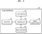
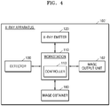
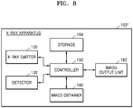
- the X-ray system 1000 may include the X-ray apparatus 100 and the workstation 110.
- the X-ray apparatus 100 may include the X-ray emitter 120 that radiates X-rays to an object 10, the detector 130 that detects X-rays radiated from the X-ray emitter 120 and transmitted through the object 10, the manipulator 140 that provides a user interface (UI) for manipulating the X-ray apparatus 100, and an image obtainer 160 that is attached to a side of the X-ray emitter 120 and photographs the object 10.
- UI user interface
- the workstation 110 may include the controller 113.
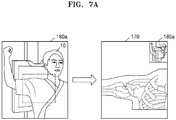
- the controller 113 may generate the image marker 180 (see FIG. 2 ) by performing image processing on a captured image of the object 10 obtained by the image obtainer 160. Also, the controller 113 may generate the X-ray image 170 (see FIG. 2 ) of the object 10 based on X-rays detected by the detector 130, and may cause the image marker 180 to overlap the generated X-ray image 170.
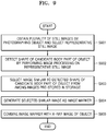
- the X-ray apparatus obtains a captured image of an object by continuously photographing the object and selects a representative still image that represents a candidate body part of the object.
- the X-ray apparatus may obtain a plurality of still images of the object by continuously photographing the object.
- the captured image of the object may be different from an X-ray image obtained by X-ray imaging the object.
- the plurality of still images may be obtained by a camera for obtaining an image.
- the image obtainer 160 (see FIG. and 3) may obtain a plurality of still images of the object 10 (see FIG. 2 ) by continuously photographing the object 10.
- an X-ray apparatus obtains a plurality of still images by continuously photographing an object, and selects a representative still image that represents a candidate body part of the object among the plurality of still images.
- the representative still image may be a still image obtained by photographing the candidate body part of the object among still images obtained immediately before X-ray imaging among the plurality of still images.
- the obtaining of the plurality of still images and the selecting of the representative still image are the same as those described in operation S501 of FIG. 5 , and thus a repeated explanation thereof will not be provided.
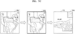
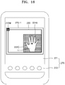
- the image marker 180 may be formed on a region of the X-ray image 170, and the guide image 190 may be included in the image marker 180.
- the guide image 190 may be an image that enables a user to recognize a vertical/horizontal direction of the image marker 180.
- the guide image 190 may be a figure image or a cartoon image including text and/or an arrow.
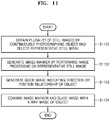
- FIG. 11 is a flowchart of a method performed by the X-ray apparatus 100 of FIG. 3 to generate an image marker including a guide image.
- the X-ray apparatus combines the image marker and the guide image with an X-ray image of the object.
- the guide image may be combined to overlap a region of the image marker.
- the image marker combined with the guide image may overlap a region of the X-ray image obtained by X-ray imaging the object and may be simultaneously displayed along with the X-ray image.
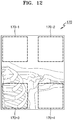
- FIG. 12 is a view for explaining a method of determining a position of an image marker according to an embodiment.
- an X-ray apparatus obtains a plurality of still images by continuously photographing an object and selects a representative still image.
- the obtaining of the plurality of still images and the selecting of the representative still image are the same as those described in operation S501 of FIG. 5 , and thus a repeated explanation thereof will not be provided.
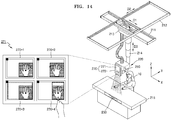
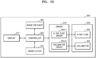
- the X-ray apparatus 200 may include an X-ray emitter 220 that generates X-rays and radiates the X-rays to the object 10, an X-ray detector 230 that detects X-rays transmitted through the object 10, an image obtainer 260 that photographs the object 10 and obtains a captured image of the object 10, and a manipulator 270 that provides an interface for manipulating the X-ray apparatus 200.
- the X-ray emitter 220 and the X-ray detector 230 are respectively the same as the X-ray emitter 120 and the detector 130 of FIG. 1 , and thus a repeated explanation thereof will not be provided.
- the X-ray apparatus 200 may display on the display 271 a UI for displaying information about the irradiation region of the X-ray emitter 220 and the central point of the X-ray emitter 220 to overlap the captured image.
- the information about the irradiation region of the X-ray emitter 220 and the central point of the X-ray emitter 220 may be a plurality of combinations of information, and each of the plurality of combinations of information may overlap the captured image to form a plurality of thumbnail images, for example, first through fourth thumbnail images 270-1 through 270-4.
- the first through fourth thumbnail images 270-1 through 270-4 may be displayed on the display 271.
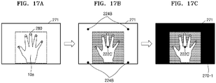
- the X-ray apparatus 200 may match the central point of the X-ray tube to the central point marker 222C' of the object 10a, and may generate the first thumbnail image 270-1 for adjusting the shutter-blade of the collimator based on the collimator coordinates 224B.
- the first thumbnail image 270-1 may be updated in real time.
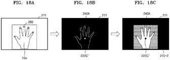
- the X-ray apparatus 200 may generate the second thumbnail image 270-2 including the central point marker 222C" of the object 10a and the X-ray imaged region UI 240A.
- the X-ray apparatus 200 may control a central point of the X-ray tube 222 (see FIG. 20 ) to be matched to the central point marker 222C" and a shutter-blade of the collimator 224 (see FIG. 20 ) to be matched to the X-ray imaged region UI 240A.
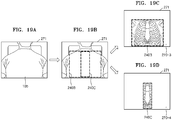
- FIGS. 19A through 19D are views for explaining a method performed by the X-ray apparatus 200 to generate the third thumbnail image 270-3 and the fourth thumbnail image 270-4 based on user experience-based learning data of an object 10b.
- Different guide UIs may be displayed on the third thumbnail image 270-3 and the fourth thumbnail image 270-4 according to an imaging protocol.
- a captured image of the object 10b may be displayed on the display 271.
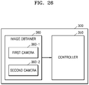
- the second camera 360-2 may be attached to a side of the X-ray emitter 320. In an embodiment, the second camera 360-2 may be attached to a collimator of the X-ray emitter 320. The second camera 360-2 may photograph the object 10 and a candidate region of the object 10 and may obtain captured images of the object 10 and the candidate region of the object 10.
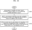
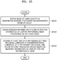
- the X-ray apparatus 300 detects an X-ray imaging condition including a luminance of the examination room, and luminances and colors of the object and the ambient area of the object by performing image processing on the captured image.
- the X-ray apparatus 300 may detect the X-ray imaging condition by performing image recognition on the captured image based on appropriate software and/or algorithms known to those skilled in the art.
- the X-ray apparatus 300 may obtain information about the luminance of the examination room by applying image recognition to the captured image of the examination room obtained by photographing the examination room.
- the X-ray apparatus 300 may obtain information about the luminances and colors of the object and/or the ambient area of the object by applying image recognition to the captured image of the object obtained by photographing the object.
- FIG. 23 is a flowchart of a method performed by the X-ray apparatus 300 of FIG. 21 to change imaging settings according to a luminance of an examination room and a luminance of an X-ray irradiation region.
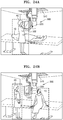
- the X-ray apparatus 300 may determine that the user 20 who stands up performs an action of talking to the object 10.
- the action of the user 20 who is standing and taking to the object 10 may mean that X-ray imaging has ended.
- the X-ray apparatus 300 may recognize an action of the object 10 as well as a behavior of the user 20.
- the X-ray apparatus 300 may recognize a current position of the user 20, that is, information about whether the user 20 is located in front of a door of the examination room or in front of the X-ray apparatus 300.
- the X-ray apparatus 300 may recognize that the user 20 is spaced apart by a predetermined distance from the X-ray apparatus 300 and the object 10 sits up and talks to the user 20, may determine that the X-ray imaging has ended, and may control a brightness of the collimator light source 322 to be reduced and a brightness of the examination room light source 370 to be increased.
- a brightness of the examination room light source 370 may be controlled according to a section or the whole of the examination room.
Landscapes
- Life Sciences & Earth Sciences (AREA)
- Health & Medical Sciences (AREA)
- Engineering & Computer Science (AREA)
- Medical Informatics (AREA)
- Pathology (AREA)
- Heart & Thoracic Surgery (AREA)
- High Energy & Nuclear Physics (AREA)
- Physics & Mathematics (AREA)
- Nuclear Medicine, Radiotherapy & Molecular Imaging (AREA)
- Optics & Photonics (AREA)
- Veterinary Medicine (AREA)
- Radiology & Medical Imaging (AREA)
- Biomedical Technology (AREA)
- Biophysics (AREA)
- Molecular Biology (AREA)
- Surgery (AREA)
- Animal Behavior & Ethology (AREA)
- General Health & Medical Sciences (AREA)
- Public Health (AREA)
- Human Computer Interaction (AREA)
- Computer Vision & Pattern Recognition (AREA)
- Apparatus For Radiation Diagnosis (AREA)
Claims (11)
- Röntgenvorrichtung (100, 100', 100", 200) zur Steuerung der Position eines Röntgenstrahlungsemitters (120, 220), wobei die Röntgenvorrichtung (100, 100', 100", 200) Folgendes umfasst:- einen Röntgenstrahlungsemitter (120, 220), der dazu konfiguriert ist, Röntgenstrahlen auf ein Objekt (10, 10a, 10b) auszustrahlen;- einen Röntgendetektor (130, 230), der dazu konfiguriert ist, durch das Objekt (10, 10a, 10b) hindurch ausgestrahlte Röntgenstrahlen zu erfassen;- eine Kamera, die dazu konfiguriert ist, ein Bild des Objekts (10, 10a, 10b) mittels Fotografieren des Objekts (10, 10a, 10b) zu erhalten, wobei das aufgenommene Bild sich von einem Röntgenbild unterscheidet, das mittels Röntgenbildgebung des Objekts (10, 10a, 10b) erhalten wurde;dadurch gekennzeichnet, dass sie weiterhin Folgendes umfasst:- eine Steuerung (113, 150, 250, 350) mit einem Bildprozessor, der dazu konfiguriert ist, einen Kandidatenbereich des Objekts (10, 10a, 10b) und einen Mittelpunkt des Objekts (10, 10a, 10b) mittels Durchführen einer Bildverarbeitung an dem erhaltenen Bild zu identifizieren,wobei die Steuerung (113, 150, 250, 350) weiterhin zu Folgendem konfiguriert ist:- Berechnen einer Vielzahl von Strahlungsbereichsformen des Röntgenstrahlungsemitters (120, 220) und von Positionen des Röntgenstrahlungsemitters (120, 220) mittels Abstimmen des Kandidatenbereichs des Objekts (10, 10a, 10b) und des Mittelpunkts des Objekts (10, 10a, 10b) mit einer Vielzahl von Strahlungsbereichen des Röntgenstrahlungsemitters (120, 220) und einer Vielzahl von Mittelpunkten des Röntgenstrahlungsemitters (120, 220) jeweils entsprechend unterschiedlichen Positionen des Röntgenstrahlungsemitters (120, 220), wobei es sich bei dem Kandidatenbereich um einen Bereich des Objekts (10, 10a, 10b) handelt, der einer Röntgenbestrahlung unterzogen werden soll; und- Erzeugen einer Vielzahl von Miniaturansichten, wobei jede der berechneten Strahlungsbereichsformen und jeder der berechneten Mittelpunkte des Röntgenstrahlungsemitters (120, 220) mit dem erhaltenen Bild überlappen;wobei die Röntgenvorrichtung (100, 100', 100", 200) weiterhin Folgendes umfasst:- eine Anzeige (111, 141, 162, 271), die dazu konfiguriert ist, die Vielzahl von Miniaturansichten anzuzeigen;- einen Benutzereingabeempfänger (112, 142), der dazu konfiguriert ist, eine Benutzereingabe zur Auswahl einer aus der Vielzahl von auf der Anzeige (111, 141, 162, 271) angezeigten Miniaturansichten zu empfangen; und- einen Treiber (254), der dazu konfiguriert ist, einen Strahlungsbereich des Röntgenstrahlungsemitters (120, 220) und eine Position des Röntgenstrahlungsemitters (120, 220) basierend auf der Benutzereingabe anzupassen.
- Röntgenvorrichtung (100, 100', 100", 200) nach Anspruch 1, wobei der Benutzereingabeempfänger (112, 142) Folgendes umfasst:
einen in der Anzeige (111, 141, 162, 271) eingebetteten Berührungsbildschirm, der dazu konfiguriert ist, eine Berührungseingabe eines Benutzers zu empfangen, bei der eine aus der Vielzahl von auf der Anzeige (111, 141, 162, 271) angezeigten Miniaturansichten berührt wird. - Röntgenvorrichtung (100, 100', 100", 200) nach Anspruch 1, wobei der Bildprozessor weiterhin zu Folgendem konfiguriert ist: Umwandeln der berechneten Strahlungsbereichsformen des Röntgenstrahlungsemitters und der berechneten Mittelpunkte des Röntgenstrahlungsemitters in virtuelle grafische Benutzeroberflächen (UIs, User Interfaces), und
wobei die Anzeige (111, 141, 162, 271) weiterhin dazu konfiguriert ist, die virtuellen grafischen UIs derart anzuzeigen, dass die virtuellen grafischen UIs mit dem erhaltenen Bild überlappen. - Röntgenvorrichtung (100, 100', 100", 200) nach Anspruch 1, wobei die Anzeige (111, 141, 162, 271) weiterhin dazu konfiguriert ist, eine UI anzuzeigen, die den Mittelpunkt des Objekts (10, 10a, 10b) als eine erste Markierung anzeigt und die berechneten Mittelpunkte des Röntgenstrahlungsemitters (120, 220) als zweite Markierungen anzeigt.
- Röntgenvorrichtung (100, 100', 100", 200) nach Anspruch 4, wobei die Positionen der zweiten Markierungen basierend auf einer Benutzereingabe korrigiert werden.
- Röntgenvorrichtung (100, 100', 100", 200) nach Anspruch 1, wobei die Steuerung (113, 150, 250, 350) weiterhin dazu konfiguriert ist, einen Benutzer zu identifizieren, der die Röntgenvorrichtung verwendet, und von dem Benutzer eingegebene Einstellungsinformationen über die Strahlungsbereiche des Röntgenstrahlungsemitters (120, 220) und die berechneten Mittelpunkte der Röntgenstrahlungsemitter (120, 220) zu erhalten, und
wobei der Bildprozessor weiterhin dazu konfiguriert ist, die Vielzahl von Miniaturansichten basierend auf den dem identifizierten Benutzer entsprechenden Einstellungsinformationen zu erzeugen. - Röntgenvorrichtung (100, 100', 100", 200) nach Anspruch 6, die weiterhin eine Speichervorrichtung (164) umfasst, die dazu konfiguriert ist, die von dem Benutzer eingegebenen Einstellungsinformationen über die Vielzahl von Strahlungsbereichen des Röntgenstrahlungsemitters (120, 220) und die berechneten Mittelpunkte des Röntgenstrahlungsemitters (120, 220) zu speichern,
wobei der Bildprozessor weiterhin dazu konfiguriert ist, durch Analysieren der in der Speichervorrichtung (164) gespeicherten Einstellungsinformationen Informationen über den Strahlungsbereich des Röntgenstrahlungsemitters (120, 220) und den Mittelpunkt des Röntgenstrahlungsemitters (120, 220) zu erhalten. - Verfahren zur Steuerung einer Position eines Röntgenstrahlungsemitters (120, 220), wobei das Verfahren Folgendes umfasst:- Erhalten (S1501) eines Bildes eines Objekts (10, 10a, 10b) mittels Fotografieren des Objekts (10, 10a, 10b), wobei das erhaltene Bild sich von einem Röntgenbild unterscheidet, das mittels Röntgenbildgebung des Objekts erhalten wurde;dadurch gekennzeichnet, dass das Verfahren weiterhin Folgendes umfasst:- Identifizieren (S1502) eines Kandidatenbereichs des Objekts (10, 10a, 10b) und eines Mittelpunktes des Objekts (10, 10a, 10b) mittels Durchführen einer Bildverarbeitung an dem erhaltenen Bild;- Berechnen (S1502) einer Vielzahl von Strahlungsbereichsformen des Röntgenstrahlungsemitters (120, 220) und von Positionen des Röntgenstrahlungsemitters (120, 220) mittels Abstimmen des identifizierten Kandidatenbereichs des Objekts (10, 10a, 10b) und des identifizierten Mittelpunkts des Objekts (10, 10a, 10b) mit einer Vielzahl von Strahlungsbereichen des Röntgenstrahlungsemitters (120, 220) und einer Vielzahl von Mittelpunkten des Röntgenstrahlungsemitters (120, 220) jeweils entsprechend unterschiedlichen Positionen des Röntgenstrahlungsemitters (120, 220), wobei es sich bei dem Kandidatenbereich um einen Bereich des Objekts (10, 10a, 10b) handelt, der einer Röntgenbestrahlung unterzogen werden soll;- Erzeugen (S1504) einer Vielzahl von Miniaturansichten, wobei jede der berechneten Strahlungsbereichsformen und jeder der berechneten Mittelpunkte des Röntgenstrahlungsemitters (120, 220) mit dem erhaltenen Bild überlappen;- Anzeigen der Vielzahl von Miniaturansichten;- Empfangen einer Benutzereingabe zur Auswahl einer aus der Vielzahl von auf einer Anzeige (111, 141, 162, 271) angezeigten Miniaturansichten; und- Abstimmen (S1505) eines Strahlungsbereichs des Röntgenstrahlungsemitters (120, 220) und einer Position des Röntgenstrahlungsemitters (120, 220) basierend auf der Benutzereingabe.
- Verfahren nach Anspruch 8, wobei das Erzeugen der Vielzahl von Miniaturansichten Folgendes umfasst:Umwandeln des Kandidatenbereichs des Objekts (10, 10a, 10b) und des Mittelpunktes des Objekts (10, 10a, 10b) in virtuelle Grafiken; undAnzeigen einer Benutzerschnittstelle (UI), so dass die virtuellen Grafiken mit dem erhaltenen Bild überlappen.
- Verfahren nach Anspruch 8, wobei das Anzeigen der Vielzahl von Miniaturansichten Folgendes umfasst:
Anzeigen einer Benutzerschnittstelle (UI), die den Mittelpunkt des Objekts (10, 10a, 10b) als eine erste Markierung anzeigt und die berechneten Mittelpunkte des Röntgenstrahlungsemitters (120, 220) als zweite Markierungen anzeigt. - Verfahren nach Anspruch 8, wobei das Erzeugen der Miniaturansichten Folgendes umfasst:Identifizieren eines Benutzers, der die den Röntgenstrahlungsemitter (120, 220) umfassende Röntgenvorrichtung (100, 100', 100", 200) verwendet; undErzeugen der Vielzahl von Miniaturansichten basierend auf von dem Benutzer eingegebenen Einstellungsinformationen über den Strahlungsbereich des Röntgenstrahlungsemitters (120, 220) und den Mittelpunkt des Röntgenstrahlungsemitters (120, 220).
Applications Claiming Priority (3)
| Application Number | Priority Date | Filing Date | Title |
|---|---|---|---|
| KR20150104359 | 2015-07-23 | ||
| KR1020160088711A KR102366255B1 (ko) | 2015-07-23 | 2016-07-13 | 엑스선 장치 및 동작 방법 |
| EP16180815.9A EP3120774B1 (de) | 2015-07-23 | 2016-07-22 | Röntgenvorrichtung und -system |
Related Parent Applications (2)
| Application Number | Title | Priority Date | Filing Date |
|---|---|---|---|
| EP16180815.9A Division EP3120774B1 (de) | 2015-07-23 | 2016-07-22 | Röntgenvorrichtung und -system |
| EP16180815.9A Division-Into EP3120774B1 (de) | 2015-07-23 | 2016-07-22 | Röntgenvorrichtung und -system |
Publications (2)
| Publication Number | Publication Date |
|---|---|
| EP3473187A1 EP3473187A1 (de) | 2019-04-24 |
| EP3473187B1 true EP3473187B1 (de) | 2020-10-28 |
Family
ID=56883506
Family Applications (2)
| Application Number | Title | Priority Date | Filing Date |
|---|---|---|---|
| EP18204140.0A Active EP3473187B1 (de) | 2015-07-23 | 2016-07-22 | Röntgenvorrichtung und verfahren |
| EP16180815.9A Active EP3120774B1 (de) | 2015-07-23 | 2016-07-22 | Röntgenvorrichtung und -system |
Family Applications After (1)
| Application Number | Title | Priority Date | Filing Date |
|---|---|---|---|
| EP16180815.9A Active EP3120774B1 (de) | 2015-07-23 | 2016-07-22 | Röntgenvorrichtung und -system |
Country Status (2)
| Country | Link |
|---|---|
| US (2) | US10172578B2 (de) |
| EP (2) | EP3473187B1 (de) |
Families Citing this family (13)
| Publication number | Priority date | Publication date | Assignee | Title |
|---|---|---|---|---|
| JP2017184875A (ja) * | 2016-04-01 | 2017-10-12 | キヤノン株式会社 | 放射線撮影システム、情報端末、放射線撮影装置、放射線撮影方法、及びプログラム |
| KR101907786B1 (ko) | 2017-04-28 | 2018-10-12 | 한국과학기술원 | 캐시 메모리를 이용한 다수의 보조 노드 무선 통신에서 노드간 협력을 통해 사용자의 체감 효과를 향상시키는 분산 저장 방법 및 장치 |
| US10925561B2 (en) * | 2017-11-17 | 2021-02-23 | Konica Minolta Healthcare Americas, Inc. | Portable digital radiography apparatus comprising a frame including a base, a digital radiography panel, and a computer |
| CN108209949A (zh) * | 2017-12-26 | 2018-06-29 | 南京巨鲨显示科技有限公司 | 一种用于医用x射线摄影系统的监测装置及监测方法 |
| JP7180104B2 (ja) | 2018-04-03 | 2022-11-30 | コニカミノルタ株式会社 | 放射線画像表示装置及び放射線撮影システム |
| CN110870779A (zh) * | 2018-08-30 | 2020-03-10 | 上海西门子医疗器械有限公司 | 数字化x线摄影设备、计算机断层扫描设备和相关方法 |
| EP3646790A1 (de) * | 2018-10-31 | 2020-05-06 | Koninklijke Philips N.V. | Führung bei der röntgenbildgebung |
| JP7350519B2 (ja) * | 2019-05-29 | 2023-09-26 | キヤノン株式会社 | 放射線撮影システム、放射線撮影制御装置及びその制御方法、並びに、プログラム |
| US11013477B2 (en) * | 2019-10-24 | 2021-05-25 | Jonathan Ross Vanhooser | Positioning guidance system for x-ray exams |
| US10702224B1 (en) * | 2019-10-24 | 2020-07-07 | Jonathan Ross Vanhooser | Positioning guidance system For X-ray exams |
| US11382582B1 (en) | 2021-08-02 | 2022-07-12 | Oxos Medical, Inc. | Imaging systems and methods |
| JP2023028949A (ja) * | 2021-08-20 | 2023-03-03 | キヤノンメディカルシステムズ株式会社 | X線撮影装置、x線撮影システム、及びx線撮影装置の制御方法 |
| EP4321101A1 (de) | 2022-08-11 | 2024-02-14 | Koninklijke Philips N.V. | Patientenbewegungsdetektion in einer diagnostischen bilderzeugung |
Family Cites Families (24)
| Publication number | Priority date | Publication date | Assignee | Title |
|---|---|---|---|---|
| GB9623575D0 (en) * | 1996-11-13 | 1997-01-08 | Univ Glasgow | Medical imaging systems |
| US6088424A (en) * | 1998-09-22 | 2000-07-11 | Vf Works, Inc. | Apparatus and method for producing a picture-in-a-picture motion x-ray image |
| DE10046091C1 (de) * | 2000-09-18 | 2002-01-17 | Siemens Ag | Computertomographiegerät und Verfahren für ein Computertomographiegerät |
| DE10315242B4 (de) * | 2003-04-03 | 2006-02-23 | Siemens Ag | Verfahren und Vorrichtung zur realitätsnahen dreidimensionalen Bildgebung |
| DE10327293A1 (de) * | 2003-06-17 | 2005-01-20 | Siemens Ag | Röntgenuntersuchungsverfahren mit automatischer Kollimation sowie zugehörige Vorrichtung |
| JP4143859B2 (ja) | 2004-09-22 | 2008-09-03 | 株式会社島津製作所 | X線透視装置 |
| JP2006204329A (ja) * | 2005-01-25 | 2006-08-10 | Hitachi Medical Corp | X線断層撮影装置 |
| DE102005062582B4 (de) * | 2005-12-27 | 2017-08-03 | Siemens Healthcare Gmbh | Abbilduingssystem und Verfahren zur Anfertigung von Röntgen- und optischen Bildern |
| JP4665774B2 (ja) | 2006-01-23 | 2011-04-06 | 株式会社島津製作所 | X線検査装置 |
| JP2009131323A (ja) * | 2007-11-28 | 2009-06-18 | Canon Inc | 撮像装置 |
| WO2009104318A1 (ja) | 2008-02-22 | 2009-08-27 | 株式会社 日立メディコ | 移動型x線装置 |
| DE102008035412A1 (de) * | 2008-07-29 | 2010-02-04 | Sirona Dental Systems Gmbh | Verfahren zur Erstellung einer dentalen 3D-Röntgenaufnahme und Röntgengerät hierfür |
| JP5451010B2 (ja) | 2008-08-29 | 2014-03-26 | キヤノン株式会社 | X線検出装置、情報処理方法および記録媒体 |
| JP2012147978A (ja) | 2011-01-20 | 2012-08-09 | Shimadzu Corp | X線撮影装置 |
| JP2012187142A (ja) | 2011-03-08 | 2012-10-04 | Toshiba Corp | X線コンピュータ断層撮影装置 |
| CN102961154B (zh) * | 2011-08-31 | 2016-07-06 | Ge医疗系统环球技术有限公司 | 调节x射线系统的曝光视场的方法及装置和x射线系统 |
| US9433395B2 (en) * | 2012-07-12 | 2016-09-06 | Samsung Electronics Co., Ltd. | X-ray imaging apparatus and method for controlling X-ray imaging apparatus |
| JP5959972B2 (ja) | 2012-07-25 | 2016-08-02 | 株式会社日立製作所 | X線診断装置 |
| US9314219B2 (en) | 2013-02-27 | 2016-04-19 | Paul J Keall | Method to estimate real-time rotation and translation of a target with a single x-ray imager |
| KR102085178B1 (ko) * | 2013-06-26 | 2020-03-05 | 삼성전자주식회사 | 의료 기기를 통한 대상체의 위치 관련 정보를 제공하는 방법 및 장치 |
| CN104345351A (zh) * | 2013-07-23 | 2015-02-11 | 清华大学 | 人体安全检查的隐私保护方法和人体安全检查系统 |
| JP2015077251A (ja) | 2013-10-16 | 2015-04-23 | 株式会社東芝 | X線撮影装置及びx線検出器収納容器 |
| WO2015081295A1 (en) * | 2013-11-27 | 2015-06-04 | Washington University | Automated apparatus to improve image quality in x-ray and associated method of use |
| JP2014198271A (ja) | 2014-07-29 | 2014-10-23 | 株式会社島津製作所 | X線撮影装置 |
-
2016
- 2016-07-22 EP EP18204140.0A patent/EP3473187B1/de active Active
- 2016-07-22 EP EP16180815.9A patent/EP3120774B1/de active Active
- 2016-07-25 US US15/218,455 patent/US10172578B2/en active Active
-
2018
- 2018-11-29 US US16/204,480 patent/US10542949B2/en active Active
Also Published As
| Publication number | Publication date |
|---|---|
| EP3473187A1 (de) | 2019-04-24 |
| EP3120774A3 (de) | 2017-03-29 |
| EP3120774A2 (de) | 2017-01-25 |
| US10542949B2 (en) | 2020-01-28 |
| US20170020469A1 (en) | 2017-01-26 |
| US10172578B2 (en) | 2019-01-08 |
| US20190110768A1 (en) | 2019-04-18 |
| EP3120774B1 (de) | 2018-12-12 |
Similar Documents
| Publication | Publication Date | Title |
|---|---|---|
| EP3473187B1 (de) | Röntgenvorrichtung und verfahren | |
| US10380718B2 (en) | Method and apparatus for displaying medical image | |
| US11564647B2 (en) | Medical imaging apparatus and method of operating same | |
| US10188365B2 (en) | X-ray apparatus and controlling method of the same | |
| EP3206583B1 (de) | Röntgenvorrichtung und röntgenbildgebungsverfahren | |
| US10772597B2 (en) | X-ray apparatus and system | |
| EP3097855B1 (de) | Verfahren und vorrichtung zum fotografieren von medizinischen bildern | |
| US20160106389A1 (en) | X-ray apparatus and x-ray imaging method | |
| EP3185773B1 (de) | Medizinische bildgebungsvorrichtung und verfahren zum betrieb davon | |
| EP3197363B1 (de) | Vorrichtung zur medizinischen bildgebung und steuerungsverfahren dafür | |
| KR102366255B1 (ko) | 엑스선 장치 및 동작 방법 | |
| EP3182897B1 (de) | Röntgenvorrichtung und verfahren zur steuerung der röntgenvorrichtung | |
| US9471980B2 (en) | Image processing apparatus, image processing method thereof, and image processing system thereof | |
| KR102487533B1 (ko) | 엑스선 장치 및 엑스선 촬영 방법 |
Legal Events
| Date | Code | Title | Description |
|---|---|---|---|
| PUAI | Public reference made under article 153(3) epc to a published international application that has entered the european phase |
Free format text: ORIGINAL CODE: 0009012 |
|
| STAA | Information on the status of an ep patent application or granted ep patent |
Free format text: STATUS: THE APPLICATION HAS BEEN PUBLISHED |
|
| AC | Divisional application: reference to earlier application |
Ref document number: 3120774 Country of ref document: EP Kind code of ref document: P |
|
| AK | Designated contracting states |
Kind code of ref document: A1 Designated state(s): AL AT BE BG CH CY CZ DE DK EE ES FI FR GB GR HR HU IE IS IT LI LT LU LV MC MK MT NL NO PL PT RO RS SE SI SK SM TR |
|
| STAA | Information on the status of an ep patent application or granted ep patent |
Free format text: STATUS: REQUEST FOR EXAMINATION WAS MADE |
|
| 17P | Request for examination filed |
Effective date: 20190722 |
|
| RBV | Designated contracting states (corrected) |
Designated state(s): AL AT BE BG CH CY CZ DE DK EE ES FI FR GB GR HR HU IE IS IT LI LT LU LV MC MK MT NL NO PL PT RO RS SE SI SK SM TR |
|
| GRAP | Despatch of communication of intention to grant a patent |
Free format text: ORIGINAL CODE: EPIDOSNIGR1 |
|
| STAA | Information on the status of an ep patent application or granted ep patent |
Free format text: STATUS: GRANT OF PATENT IS INTENDED |
|
| INTG | Intention to grant announced |
Effective date: 20200630 |
|
| GRAS | Grant fee paid |
Free format text: ORIGINAL CODE: EPIDOSNIGR3 |
|
| GRAA | (expected) grant |
Free format text: ORIGINAL CODE: 0009210 |
|
| STAA | Information on the status of an ep patent application or granted ep patent |
Free format text: STATUS: THE PATENT HAS BEEN GRANTED |
|
| AC | Divisional application: reference to earlier application |
Ref document number: 3120774 Country of ref document: EP Kind code of ref document: P |
|
| AK | Designated contracting states |
Kind code of ref document: B1 Designated state(s): AL AT BE BG CH CY CZ DE DK EE ES FI FR GB GR HR HU IE IS IT LI LT LU LV MC MK MT NL NO PL PT RO RS SE SI SK SM TR |
|
| REG | Reference to a national code |
Ref country code: GB Ref legal event code: FG4D |
|
| REG | Reference to a national code |
Ref country code: CH Ref legal event code: EP |
|
| REG | Reference to a national code |
Ref country code: DE Ref legal event code: R096 Ref document number: 602016046953 Country of ref document: DE |
|
| REG | Reference to a national code |
Ref country code: AT Ref legal event code: REF Ref document number: 1327376 Country of ref document: AT Kind code of ref document: T Effective date: 20201115 |
|
| REG | Reference to a national code |
Ref country code: IE Ref legal event code: FG4D |
|
| REG | Reference to a national code |
Ref country code: AT Ref legal event code: MK05 Ref document number: 1327376 Country of ref document: AT Kind code of ref document: T Effective date: 20201028 |
|
| REG | Reference to a national code |
Ref country code: NL Ref legal event code: MP Effective date: 20201028 |
|
| PG25 | Lapsed in a contracting state [announced via postgrant information from national office to epo] |
Ref country code: GR Free format text: LAPSE BECAUSE OF FAILURE TO SUBMIT A TRANSLATION OF THE DESCRIPTION OR TO PAY THE FEE WITHIN THE PRESCRIBED TIME-LIMIT Effective date: 20210129 Ref country code: NO Free format text: LAPSE BECAUSE OF FAILURE TO SUBMIT A TRANSLATION OF THE DESCRIPTION OR TO PAY THE FEE WITHIN THE PRESCRIBED TIME-LIMIT Effective date: 20210128 Ref country code: RS Free format text: LAPSE BECAUSE OF FAILURE TO SUBMIT A TRANSLATION OF THE DESCRIPTION OR TO PAY THE FEE WITHIN THE PRESCRIBED TIME-LIMIT Effective date: 20201028 Ref country code: PT Free format text: LAPSE BECAUSE OF FAILURE TO SUBMIT A TRANSLATION OF THE DESCRIPTION OR TO PAY THE FEE WITHIN THE PRESCRIBED TIME-LIMIT Effective date: 20210301 Ref country code: FI Free format text: LAPSE BECAUSE OF FAILURE TO SUBMIT A TRANSLATION OF THE DESCRIPTION OR TO PAY THE FEE WITHIN THE PRESCRIBED TIME-LIMIT Effective date: 20201028 |
|
| REG | Reference to a national code |
Ref country code: LT Ref legal event code: MG4D |
|
| PG25 | Lapsed in a contracting state [announced via postgrant information from national office to epo] |
Ref country code: SE Free format text: LAPSE BECAUSE OF FAILURE TO SUBMIT A TRANSLATION OF THE DESCRIPTION OR TO PAY THE FEE WITHIN THE PRESCRIBED TIME-LIMIT Effective date: 20201028 Ref country code: LV Free format text: LAPSE BECAUSE OF FAILURE TO SUBMIT A TRANSLATION OF THE DESCRIPTION OR TO PAY THE FEE WITHIN THE PRESCRIBED TIME-LIMIT Effective date: 20201028 Ref country code: IS Free format text: LAPSE BECAUSE OF FAILURE TO SUBMIT A TRANSLATION OF THE DESCRIPTION OR TO PAY THE FEE WITHIN THE PRESCRIBED TIME-LIMIT Effective date: 20210228 Ref country code: PL Free format text: LAPSE BECAUSE OF FAILURE TO SUBMIT A TRANSLATION OF THE DESCRIPTION OR TO PAY THE FEE WITHIN THE PRESCRIBED TIME-LIMIT Effective date: 20201028 Ref country code: BG Free format text: LAPSE BECAUSE OF FAILURE TO SUBMIT A TRANSLATION OF THE DESCRIPTION OR TO PAY THE FEE WITHIN THE PRESCRIBED TIME-LIMIT Effective date: 20210128 Ref country code: AT Free format text: LAPSE BECAUSE OF FAILURE TO SUBMIT A TRANSLATION OF THE DESCRIPTION OR TO PAY THE FEE WITHIN THE PRESCRIBED TIME-LIMIT Effective date: 20201028 Ref country code: ES Free format text: LAPSE BECAUSE OF FAILURE TO SUBMIT A TRANSLATION OF THE DESCRIPTION OR TO PAY THE FEE WITHIN THE PRESCRIBED TIME-LIMIT Effective date: 20201028 |
|
| PG25 | Lapsed in a contracting state [announced via postgrant information from national office to epo] |
Ref country code: HR Free format text: LAPSE BECAUSE OF FAILURE TO SUBMIT A TRANSLATION OF THE DESCRIPTION OR TO PAY THE FEE WITHIN THE PRESCRIBED TIME-LIMIT Effective date: 20201028 Ref country code: NL Free format text: LAPSE BECAUSE OF FAILURE TO SUBMIT A TRANSLATION OF THE DESCRIPTION OR TO PAY THE FEE WITHIN THE PRESCRIBED TIME-LIMIT Effective date: 20201028 |
|
| REG | Reference to a national code |
Ref country code: DE Ref legal event code: R097 Ref document number: 602016046953 Country of ref document: DE |
|
| PG25 | Lapsed in a contracting state [announced via postgrant information from national office to epo] |
Ref country code: CZ Free format text: LAPSE BECAUSE OF FAILURE TO SUBMIT A TRANSLATION OF THE DESCRIPTION OR TO PAY THE FEE WITHIN THE PRESCRIBED TIME-LIMIT Effective date: 20201028 Ref country code: EE Free format text: LAPSE BECAUSE OF FAILURE TO SUBMIT A TRANSLATION OF THE DESCRIPTION OR TO PAY THE FEE WITHIN THE PRESCRIBED TIME-LIMIT Effective date: 20201028 Ref country code: SM Free format text: LAPSE BECAUSE OF FAILURE TO SUBMIT A TRANSLATION OF THE DESCRIPTION OR TO PAY THE FEE WITHIN THE PRESCRIBED TIME-LIMIT Effective date: 20201028 Ref country code: SK Free format text: LAPSE BECAUSE OF FAILURE TO SUBMIT A TRANSLATION OF THE DESCRIPTION OR TO PAY THE FEE WITHIN THE PRESCRIBED TIME-LIMIT Effective date: 20201028 Ref country code: LT Free format text: LAPSE BECAUSE OF FAILURE TO SUBMIT A TRANSLATION OF THE DESCRIPTION OR TO PAY THE FEE WITHIN THE PRESCRIBED TIME-LIMIT Effective date: 20201028 Ref country code: RO Free format text: LAPSE BECAUSE OF FAILURE TO SUBMIT A TRANSLATION OF THE DESCRIPTION OR TO PAY THE FEE WITHIN THE PRESCRIBED TIME-LIMIT Effective date: 20201028 |
|
| PG25 | Lapsed in a contracting state [announced via postgrant information from national office to epo] |
Ref country code: DK Free format text: LAPSE BECAUSE OF FAILURE TO SUBMIT A TRANSLATION OF THE DESCRIPTION OR TO PAY THE FEE WITHIN THE PRESCRIBED TIME-LIMIT Effective date: 20201028 |
|
| PLBE | No opposition filed within time limit |
Free format text: ORIGINAL CODE: 0009261 |
|
| STAA | Information on the status of an ep patent application or granted ep patent |
Free format text: STATUS: NO OPPOSITION FILED WITHIN TIME LIMIT |
|
| 26N | No opposition filed |
Effective date: 20210729 |
|
| PG25 | Lapsed in a contracting state [announced via postgrant information from national office to epo] |
Ref country code: IT Free format text: LAPSE BECAUSE OF FAILURE TO SUBMIT A TRANSLATION OF THE DESCRIPTION OR TO PAY THE FEE WITHIN THE PRESCRIBED TIME-LIMIT Effective date: 20201028 Ref country code: AL Free format text: LAPSE BECAUSE OF FAILURE TO SUBMIT A TRANSLATION OF THE DESCRIPTION OR TO PAY THE FEE WITHIN THE PRESCRIBED TIME-LIMIT Effective date: 20201028 |
|
| PG25 | Lapsed in a contracting state [announced via postgrant information from national office to epo] |
Ref country code: SI Free format text: LAPSE BECAUSE OF FAILURE TO SUBMIT A TRANSLATION OF THE DESCRIPTION OR TO PAY THE FEE WITHIN THE PRESCRIBED TIME-LIMIT Effective date: 20201028 |
|
| REG | Reference to a national code |
Ref country code: CH Ref legal event code: PL |
|
| PG25 | Lapsed in a contracting state [announced via postgrant information from national office to epo] |
Ref country code: MC Free format text: LAPSE BECAUSE OF FAILURE TO SUBMIT A TRANSLATION OF THE DESCRIPTION OR TO PAY THE FEE WITHIN THE PRESCRIBED TIME-LIMIT Effective date: 20201028 |
|
| REG | Reference to a national code |
Ref country code: BE Ref legal event code: MM Effective date: 20210731 |
|
| PG25 | Lapsed in a contracting state [announced via postgrant information from national office to epo] |
Ref country code: LI Free format text: LAPSE BECAUSE OF NON-PAYMENT OF DUE FEES Effective date: 20210731 Ref country code: CH Free format text: LAPSE BECAUSE OF NON-PAYMENT OF DUE FEES Effective date: 20210731 |
|
| PG25 | Lapsed in a contracting state [announced via postgrant information from national office to epo] |
Ref country code: IS Free format text: LAPSE BECAUSE OF FAILURE TO SUBMIT A TRANSLATION OF THE DESCRIPTION OR TO PAY THE FEE WITHIN THE PRESCRIBED TIME-LIMIT Effective date: 20210228 Ref country code: LU Free format text: LAPSE BECAUSE OF NON-PAYMENT OF DUE FEES Effective date: 20210722 Ref country code: FR Free format text: LAPSE BECAUSE OF NON-PAYMENT OF DUE FEES Effective date: 20210731 |
|
| PG25 | Lapsed in a contracting state [announced via postgrant information from national office to epo] |
Ref country code: IE Free format text: LAPSE BECAUSE OF NON-PAYMENT OF DUE FEES Effective date: 20210722 Ref country code: BE Free format text: LAPSE BECAUSE OF NON-PAYMENT OF DUE FEES Effective date: 20210731 |
|
| PG25 | Lapsed in a contracting state [announced via postgrant information from national office to epo] |
Ref country code: CY Free format text: LAPSE BECAUSE OF FAILURE TO SUBMIT A TRANSLATION OF THE DESCRIPTION OR TO PAY THE FEE WITHIN THE PRESCRIBED TIME-LIMIT Effective date: 20201028 |
|
| PG25 | Lapsed in a contracting state [announced via postgrant information from national office to epo] |
Ref country code: HU Free format text: LAPSE BECAUSE OF FAILURE TO SUBMIT A TRANSLATION OF THE DESCRIPTION OR TO PAY THE FEE WITHIN THE PRESCRIBED TIME-LIMIT; INVALID AB INITIO Effective date: 20160722 |
|
| PGFP | Annual fee paid to national office [announced via postgrant information from national office to epo] |
Ref country code: DE Payment date: 20230620 Year of fee payment: 8 |
|
| PG25 | Lapsed in a contracting state [announced via postgrant information from national office to epo] |
Ref country code: MK Free format text: LAPSE BECAUSE OF FAILURE TO SUBMIT A TRANSLATION OF THE DESCRIPTION OR TO PAY THE FEE WITHIN THE PRESCRIBED TIME-LIMIT Effective date: 20201028 |
|
| PGFP | Annual fee paid to national office [announced via postgrant information from national office to epo] |
Ref country code: GB Payment date: 20240620 Year of fee payment: 9 |