EP3473187B1 - X-ray apparatus and method - Google Patents
X-ray apparatus and method Download PDFInfo
- Publication number
- EP3473187B1 EP3473187B1 EP18204140.0A EP18204140A EP3473187B1 EP 3473187 B1 EP3473187 B1 EP 3473187B1 EP 18204140 A EP18204140 A EP 18204140A EP 3473187 B1 EP3473187 B1 EP 3473187B1
- Authority
- EP
- European Patent Office
- Prior art keywords
- ray
- image
- ray emitter
- user
- ray apparatus
- Prior art date
- Legal status (The legal status is an assumption and is not a legal conclusion. Google has not performed a legal analysis and makes no representation as to the accuracy of the status listed.)
- Active
Links
- 238000000034 method Methods 0.000 title claims description 55
- 239000003550 marker Substances 0.000 claims description 124
- 238000012545 processing Methods 0.000 claims description 71
- 238000003384 imaging method Methods 0.000 claims description 70
- 235000019557 luminance Nutrition 0.000 description 42
- 238000004891 communication Methods 0.000 description 19
- 230000006399 behavior Effects 0.000 description 13
- 238000010586 diagram Methods 0.000 description 12
- 230000005855 radiation Effects 0.000 description 11
- 230000009471 action Effects 0.000 description 10
- 230000008859 change Effects 0.000 description 10
- 239000013077 target material Substances 0.000 description 9
- 210000000038 chest Anatomy 0.000 description 8
- 230000015654 memory Effects 0.000 description 7
- 238000002059 diagnostic imaging Methods 0.000 description 5
- 238000010438 heat treatment Methods 0.000 description 5
- 238000002591 computed tomography Methods 0.000 description 4
- 230000006870 function Effects 0.000 description 4
- 210000003128 head Anatomy 0.000 description 4
- 238000010191 image analysis Methods 0.000 description 4
- 230000009545 invasion Effects 0.000 description 4
- PXHVJJICTQNCMI-UHFFFAOYSA-N Nickel Chemical compound [Ni] PXHVJJICTQNCMI-UHFFFAOYSA-N 0.000 description 3
- 239000003086 colorant Substances 0.000 description 3
- 238000005516 engineering process Methods 0.000 description 3
- 238000002595 magnetic resonance imaging Methods 0.000 description 3
- 238000003672 processing method Methods 0.000 description 3
- 241001465754 Metazoa Species 0.000 description 2
- 210000001015 abdomen Anatomy 0.000 description 2
- 210000000481 breast Anatomy 0.000 description 2
- 238000004364 calculation method Methods 0.000 description 2
- 239000011651 chromium Substances 0.000 description 2
- 238000010276 construction Methods 0.000 description 2
- 238000003745 diagnosis Methods 0.000 description 2
- 201000010099 disease Diseases 0.000 description 2
- 208000037265 diseases, disorders, signs and symptoms Diseases 0.000 description 2
- 239000000463 material Substances 0.000 description 2
- 230000001360 synchronised effect Effects 0.000 description 2
- 239000010409 thin film Substances 0.000 description 2
- WFKWXMTUELFFGS-UHFFFAOYSA-N tungsten Chemical compound [W] WFKWXMTUELFFGS-UHFFFAOYSA-N 0.000 description 2
- 229910052721 tungsten Inorganic materials 0.000 description 2
- 239000010937 tungsten Substances 0.000 description 2
- VYZAMTAEIAYCRO-UHFFFAOYSA-N Chromium Chemical compound [Cr] VYZAMTAEIAYCRO-UHFFFAOYSA-N 0.000 description 1
- RYGMFSIKBFXOCR-UHFFFAOYSA-N Copper Chemical compound [Cu] RYGMFSIKBFXOCR-UHFFFAOYSA-N 0.000 description 1
- XEEYBQQBJWHFJM-UHFFFAOYSA-N Iron Chemical compound [Fe] XEEYBQQBJWHFJM-UHFFFAOYSA-N 0.000 description 1
- ZOKXTWBITQBERF-UHFFFAOYSA-N Molybdenum Chemical compound [Mo] ZOKXTWBITQBERF-UHFFFAOYSA-N 0.000 description 1
- 238000009825 accumulation Methods 0.000 description 1
- 238000002583 angiography Methods 0.000 description 1
- 229910052790 beryllium Inorganic materials 0.000 description 1
- ATBAMAFKBVZNFJ-UHFFFAOYSA-N beryllium atom Chemical compound [Be] ATBAMAFKBVZNFJ-UHFFFAOYSA-N 0.000 description 1
- 230000005540 biological transmission Effects 0.000 description 1
- 210000004204 blood vessel Anatomy 0.000 description 1
- 210000004556 brain Anatomy 0.000 description 1
- 238000006243 chemical reaction Methods 0.000 description 1
- 229910052804 chromium Inorganic materials 0.000 description 1
- 239000010941 cobalt Substances 0.000 description 1
- 229910017052 cobalt Inorganic materials 0.000 description 1
- GUTLYIVDDKVIGB-UHFFFAOYSA-N cobalt atom Chemical compound [Co] GUTLYIVDDKVIGB-UHFFFAOYSA-N 0.000 description 1
- 230000000295 complement effect Effects 0.000 description 1
- 229910052802 copper Inorganic materials 0.000 description 1
- 239000010949 copper Substances 0.000 description 1
- 230000001419 dependent effect Effects 0.000 description 1
- 238000001514 detection method Methods 0.000 description 1
- 239000003814 drug Substances 0.000 description 1
- 230000001747 exhibiting effect Effects 0.000 description 1
- 239000004973 liquid crystal related substance Substances 0.000 description 1
- 210000004185 liver Anatomy 0.000 description 1
- 230000033001 locomotion Effects 0.000 description 1
- 238000010295 mobile communication Methods 0.000 description 1
- 238000012986 modification Methods 0.000 description 1
- 230000004048 modification Effects 0.000 description 1
- 229910052750 molybdenum Inorganic materials 0.000 description 1
- 239000011733 molybdenum Substances 0.000 description 1
- 229910052759 nickel Inorganic materials 0.000 description 1
- 238000009659 non-destructive testing Methods 0.000 description 1
- 230000003287 optical effect Effects 0.000 description 1
- 239000013307 optical fiber Substances 0.000 description 1
- 210000000056 organ Anatomy 0.000 description 1
- 210000003695 paranasal sinus Anatomy 0.000 description 1
- 238000007781 pre-processing Methods 0.000 description 1
- 230000008569 process Effects 0.000 description 1
- 230000008439 repair process Effects 0.000 description 1
- 230000004044 response Effects 0.000 description 1
- 239000004065 semiconductor Substances 0.000 description 1
- 230000011664 signaling Effects 0.000 description 1
- 210000004872 soft tissue Anatomy 0.000 description 1
- 230000003068 static effect Effects 0.000 description 1
- 230000009466 transformation Effects 0.000 description 1
- 238000002834 transmittance Methods 0.000 description 1
- 238000002604 ultrasonography Methods 0.000 description 1
Images


Classifications
-
- A—HUMAN NECESSITIES
- A61—MEDICAL OR VETERINARY SCIENCE; HYGIENE
- A61B—DIAGNOSIS; SURGERY; IDENTIFICATION
- A61B6/00—Apparatus for radiation diagnosis, e.g. combined with radiation therapy equipment
- A61B6/44—Constructional features of apparatus for radiation diagnosis
- A61B6/4417—Constructional features of apparatus for radiation diagnosis related to combined acquisition of different diagnostic modalities
-
- A—HUMAN NECESSITIES
- A61—MEDICAL OR VETERINARY SCIENCE; HYGIENE
- A61B—DIAGNOSIS; SURGERY; IDENTIFICATION
- A61B6/00—Apparatus for radiation diagnosis, e.g. combined with radiation therapy equipment
- A61B6/08—Auxiliary means for directing the radiation beam to a particular spot, e.g. using light beams
-
- A—HUMAN NECESSITIES
- A61—MEDICAL OR VETERINARY SCIENCE; HYGIENE
- A61B—DIAGNOSIS; SURGERY; IDENTIFICATION
- A61B6/00—Apparatus for radiation diagnosis, e.g. combined with radiation therapy equipment
- A61B6/44—Constructional features of apparatus for radiation diagnosis
- A61B6/4476—Constructional features of apparatus for radiation diagnosis related to motor-assisted motion of the source unit
-
- A—HUMAN NECESSITIES
- A61—MEDICAL OR VETERINARY SCIENCE; HYGIENE
- A61B—DIAGNOSIS; SURGERY; IDENTIFICATION
- A61B6/00—Apparatus for radiation diagnosis, e.g. combined with radiation therapy equipment
- A61B6/46—Apparatus for radiation diagnosis, e.g. combined with radiation therapy equipment with special arrangements for interfacing with the operator or the patient
- A61B6/461—Displaying means of special interest
- A61B6/463—Displaying means of special interest characterised by displaying multiple images or images and diagnostic data on one display
-
- A—HUMAN NECESSITIES
- A61—MEDICAL OR VETERINARY SCIENCE; HYGIENE
- A61B—DIAGNOSIS; SURGERY; IDENTIFICATION
- A61B6/00—Apparatus for radiation diagnosis, e.g. combined with radiation therapy equipment
- A61B6/52—Devices using data or image processing specially adapted for radiation diagnosis
-
- A—HUMAN NECESSITIES
- A61—MEDICAL OR VETERINARY SCIENCE; HYGIENE
- A61B—DIAGNOSIS; SURGERY; IDENTIFICATION
- A61B6/00—Apparatus for radiation diagnosis, e.g. combined with radiation therapy equipment
- A61B6/54—Control of apparatus or devices for radiation diagnosis
-
- A—HUMAN NECESSITIES
- A61—MEDICAL OR VETERINARY SCIENCE; HYGIENE
- A61B—DIAGNOSIS; SURGERY; IDENTIFICATION
- A61B6/00—Apparatus for radiation diagnosis, e.g. combined with radiation therapy equipment
- A61B6/44—Constructional features of apparatus for radiation diagnosis
- A61B6/4429—Constructional features of apparatus for radiation diagnosis related to the mounting of source units and detector units
- A61B6/4452—Constructional features of apparatus for radiation diagnosis related to the mounting of source units and detector units the source unit and the detector unit being able to move relative to each other
-
- A—HUMAN NECESSITIES
- A61—MEDICAL OR VETERINARY SCIENCE; HYGIENE
- A61B—DIAGNOSIS; SURGERY; IDENTIFICATION
- A61B6/00—Apparatus for radiation diagnosis, e.g. combined with radiation therapy equipment
- A61B6/44—Constructional features of apparatus for radiation diagnosis
- A61B6/4429—Constructional features of apparatus for radiation diagnosis related to the mounting of source units and detector units
- A61B6/4464—Constructional features of apparatus for radiation diagnosis related to the mounting of source units and detector units the source unit or the detector unit being mounted to ceiling
-
- A—HUMAN NECESSITIES
- A61—MEDICAL OR VETERINARY SCIENCE; HYGIENE
- A61B—DIAGNOSIS; SURGERY; IDENTIFICATION
- A61B6/00—Apparatus for radiation diagnosis, e.g. combined with radiation therapy equipment
- A61B6/54—Control of apparatus or devices for radiation diagnosis
- A61B6/545—Control of apparatus or devices for radiation diagnosis involving automatic set-up of acquisition parameters
-
- A—HUMAN NECESSITIES
- A61—MEDICAL OR VETERINARY SCIENCE; HYGIENE
- A61B—DIAGNOSIS; SURGERY; IDENTIFICATION
- A61B6/00—Apparatus for radiation diagnosis, e.g. combined with radiation therapy equipment
- A61B6/58—Testing, adjusting or calibrating apparatus or devices for radiation diagnosis
- A61B6/587—Alignment of source unit to detector unit
Definitions
- the X-ray apparatus 100 may be controlled via the workstation 110 or may be controlled by the controller 150 included in the X-ray apparatus 100. Accordingly, the user may control the X-ray apparatus 100 via the workstation 110 or may control the X-ray apparatus 100 via the manipulator 140 and the controller 150 included in the X-ray apparatus 100. In other words, the user may remotely control the X-ray apparatus 100 via the workstation 110 or may directly control the X-ray apparatus 100.
- a prepare command for performing a pre-heating operation for X-ray radiation may be input through the switch, and then, when the user pushes the switch once more, the radiation command for performing substantial X-ray radiation may be input through the switch.
- the controllers 113 and 150 generate signals corresponding to the commands input through the switch manipulation, that is, a prepare signal, and transmit the generated signals to the high voltage generator 121 for generating a high voltage for generating the X-ray.
- the communicator may include one or more elements enabling communication with external apparatuses.
- the communicator may include a local area communication module, a wired communication module, and a wireless communication module.
- the X-ray system 1000 may include the X-ray apparatus 100 and the workstation 110.
- the X-ray apparatus 100 may include the X-ray emitter 120 that radiates X-rays to an object 10, the detector 130 that detects X-rays radiated from the X-ray emitter 120 and transmitted through the object 10, the manipulator 140 that provides a user interface (UI) for manipulating the X-ray apparatus 100, and an image obtainer 160 that is attached to a side of the X-ray emitter 120 and photographs the object 10.
- UI user interface
- the workstation 110 may include the controller 113.
- the controller 113 may generate the image marker 180 (see FIG. 2 ) by performing image processing on a captured image of the object 10 obtained by the image obtainer 160. Also, the controller 113 may generate the X-ray image 170 (see FIG. 2 ) of the object 10 based on X-rays detected by the detector 130, and may cause the image marker 180 to overlap the generated X-ray image 170.
- the X-ray apparatus obtains a captured image of an object by continuously photographing the object and selects a representative still image that represents a candidate body part of the object.
- the X-ray apparatus may obtain a plurality of still images of the object by continuously photographing the object.
- the captured image of the object may be different from an X-ray image obtained by X-ray imaging the object.
- the plurality of still images may be obtained by a camera for obtaining an image.
- the image obtainer 160 (see FIG. and 3) may obtain a plurality of still images of the object 10 (see FIG. 2 ) by continuously photographing the object 10.
- an X-ray apparatus obtains a plurality of still images by continuously photographing an object, and selects a representative still image that represents a candidate body part of the object among the plurality of still images.
- the representative still image may be a still image obtained by photographing the candidate body part of the object among still images obtained immediately before X-ray imaging among the plurality of still images.
- the obtaining of the plurality of still images and the selecting of the representative still image are the same as those described in operation S501 of FIG. 5 , and thus a repeated explanation thereof will not be provided.
- the image marker 180 may be formed on a region of the X-ray image 170, and the guide image 190 may be included in the image marker 180.
- the guide image 190 may be an image that enables a user to recognize a vertical/horizontal direction of the image marker 180.
- the guide image 190 may be a figure image or a cartoon image including text and/or an arrow.
- FIG. 11 is a flowchart of a method performed by the X-ray apparatus 100 of FIG. 3 to generate an image marker including a guide image.
- the X-ray apparatus combines the image marker and the guide image with an X-ray image of the object.
- the guide image may be combined to overlap a region of the image marker.
- the image marker combined with the guide image may overlap a region of the X-ray image obtained by X-ray imaging the object and may be simultaneously displayed along with the X-ray image.
- FIG. 12 is a view for explaining a method of determining a position of an image marker according to an embodiment.
- an X-ray apparatus obtains a plurality of still images by continuously photographing an object and selects a representative still image.
- the obtaining of the plurality of still images and the selecting of the representative still image are the same as those described in operation S501 of FIG. 5 , and thus a repeated explanation thereof will not be provided.
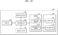
- the X-ray apparatus 200 may include an X-ray emitter 220 that generates X-rays and radiates the X-rays to the object 10, an X-ray detector 230 that detects X-rays transmitted through the object 10, an image obtainer 260 that photographs the object 10 and obtains a captured image of the object 10, and a manipulator 270 that provides an interface for manipulating the X-ray apparatus 200.
- the X-ray emitter 220 and the X-ray detector 230 are respectively the same as the X-ray emitter 120 and the detector 130 of FIG. 1 , and thus a repeated explanation thereof will not be provided.
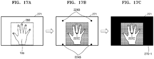
- the X-ray apparatus 200 may display on the display 271 a UI for displaying information about the irradiation region of the X-ray emitter 220 and the central point of the X-ray emitter 220 to overlap the captured image.
- the information about the irradiation region of the X-ray emitter 220 and the central point of the X-ray emitter 220 may be a plurality of combinations of information, and each of the plurality of combinations of information may overlap the captured image to form a plurality of thumbnail images, for example, first through fourth thumbnail images 270-1 through 270-4.
- the first through fourth thumbnail images 270-1 through 270-4 may be displayed on the display 271.
- the X-ray apparatus 200 may match the central point of the X-ray tube to the central point marker 222C' of the object 10a, and may generate the first thumbnail image 270-1 for adjusting the shutter-blade of the collimator based on the collimator coordinates 224B.
- the first thumbnail image 270-1 may be updated in real time.
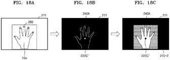
- the X-ray apparatus 200 may generate the second thumbnail image 270-2 including the central point marker 222C" of the object 10a and the X-ray imaged region UI 240A.
- the X-ray apparatus 200 may control a central point of the X-ray tube 222 (see FIG. 20 ) to be matched to the central point marker 222C" and a shutter-blade of the collimator 224 (see FIG. 20 ) to be matched to the X-ray imaged region UI 240A.
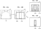
- FIGS. 19A through 19D are views for explaining a method performed by the X-ray apparatus 200 to generate the third thumbnail image 270-3 and the fourth thumbnail image 270-4 based on user experience-based learning data of an object 10b.
- Different guide UIs may be displayed on the third thumbnail image 270-3 and the fourth thumbnail image 270-4 according to an imaging protocol.
- a captured image of the object 10b may be displayed on the display 271.
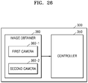
- the second camera 360-2 may be attached to a side of the X-ray emitter 320. In an embodiment, the second camera 360-2 may be attached to a collimator of the X-ray emitter 320. The second camera 360-2 may photograph the object 10 and a candidate region of the object 10 and may obtain captured images of the object 10 and the candidate region of the object 10.
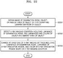
- the X-ray apparatus 300 detects an X-ray imaging condition including a luminance of the examination room, and luminances and colors of the object and the ambient area of the object by performing image processing on the captured image.
- the X-ray apparatus 300 may detect the X-ray imaging condition by performing image recognition on the captured image based on appropriate software and/or algorithms known to those skilled in the art.
- the X-ray apparatus 300 may obtain information about the luminance of the examination room by applying image recognition to the captured image of the examination room obtained by photographing the examination room.
- the X-ray apparatus 300 may obtain information about the luminances and colors of the object and/or the ambient area of the object by applying image recognition to the captured image of the object obtained by photographing the object.
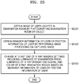
- FIG. 23 is a flowchart of a method performed by the X-ray apparatus 300 of FIG. 21 to change imaging settings according to a luminance of an examination room and a luminance of an X-ray irradiation region.
- the X-ray apparatus 300 may determine that the user 20 who stands up performs an action of talking to the object 10.
- the action of the user 20 who is standing and taking to the object 10 may mean that X-ray imaging has ended.
- the X-ray apparatus 300 may recognize an action of the object 10 as well as a behavior of the user 20.
- the X-ray apparatus 300 may recognize a current position of the user 20, that is, information about whether the user 20 is located in front of a door of the examination room or in front of the X-ray apparatus 300.
- the X-ray apparatus 300 may recognize that the user 20 is spaced apart by a predetermined distance from the X-ray apparatus 300 and the object 10 sits up and talks to the user 20, may determine that the X-ray imaging has ended, and may control a brightness of the collimator light source 322 to be reduced and a brightness of the examination room light source 370 to be increased.
- a brightness of the examination room light source 370 may be controlled according to a section or the whole of the examination room.
Description
- Apparatuses consistent with embodiments relate to X-ray apparatuses and systems, and more particularly, to X-ray apparatuses and systems that may obtain an image of an object photographed by using a camera attached to the X-ray apparatuses and may use the obtained image to capture an X-ray image.
- The X-rays are electromagnetic waves having wavelengths ranging from 0.01 to 100 Å, and may pass through an object and thus are widely used in medical devices for imaging the inside of a living body or are used as non-destructive testing devices in the industry.
- An X-ray apparatus using X-rays may obtain an X-ray image of an object by transmitting X-rays emitted from an X-ray source through the object and detecting a strength difference between the transmitted X-rays by using an X-ray detector. Accordingly, an internal structure of the object may be detected and the object may be diagnosed by using the X-ray image. The X-ray apparatus easily detects the inner structure of the object by using the fact that transmittances of the X-rays vary according to a density of the object and atomic numbers of atoms constituting the object.
- Herewith reference is made to
US 2013/0077745 A1 , which discloses a method and corresponding apparatus for adjusting a field of view for exposure of an X-ray system, said method comprising manually selecting a region or point of interest on an image obtained by a camera and subsequently automatically positioning an X-ray source at a target position corresponding to the selected region or point of interest. - Further prior-art documents considered to constitute relevant prior-art are
US 2005/013410 A1 andWO 2015/081295 A1 . - In accordance with a general aspect of the present invention, there is provided an X-ray apparatus exhibiting the features specified in the appended independent apparatus claim.
- In accordance with another general aspect of the present invention, there is provided a method of controlling a position of an X-ray emitter, said method comprising the steps specified in the appended independent method claim.
- Preferred embodiments of the apparatus and method in accordance with the present invention are subject of the appended dependent apparatus and method claims.
- The above and/or other aspects will become more apparent by describing certain embodiments with reference to the accompanying drawings, in which:
-
FIG. 1 is a block diagram illustrating a configuration of an X-ray system; -
FIG. 2 is a conceptual view for explaining a method of generating an image marker according to an embodiment; -
FIG. 3 is a block diagram of an X-ray apparatus according to an embodiment; -
FIG. 4 is a block diagram of an X-ray apparatus according to an embodiment; -
FIG. 5 is a flowchart of a method performed by the X-ray apparatus to generate an image marker according to an embodiment; -
FIGS. 6A through 6C are views for explaining a method of correcting a captured image according to an embodiment; -
FIGS. 7A through 7D are views for explaining an image processing method of generating an image marker by using a representative still image according to an embodiment; -
FIG. 8 is a block diagram of an X-ray apparatus according to an embodiment; -
FIG. 9 is a flowchart of a method performed by the X-ray apparatus ofFIG. 8 to generate an image marker; -
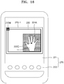
FIG. 10 shows an X-ray image including an image marker and a guide image according to an embodiment; -
FIG. 11 is a flowchart of a method performed by the X-ray apparatus to generate an image marker including a guide image according to an embodiment; -
FIG. 12 is a view for explaining a method of determining a position of an image marker according to an embodiment; -
FIG. 13 is a flowchart of a method performed by the X-ray apparatus to determine a position of an image marker according to an embodiment; -
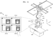
FIG. 14 is a conceptual view for explaining a method of adjusting positions of mechanical devices of an X-ray apparatus according to an embodiment; -
FIG. 15 is a flowchart of a method performed by the X-ray apparatus to adjust a position of a mechanical device according to an embodiment; -
FIG. 16 is a view of a manipulator for displaying a mechanical device setting guide user interface (UI) according to an embodiment; -
FIGS. 17A through 19D are views for explaining a method of adjusting a mechanical device according to an embodiment; -
FIG. 20 is a block diagram of the X-ray apparatus according to an embodiment; -
FIG. 21 is a conceptual view for explaining a method performed by an X-ray apparatus to control an X-ray imaging condition by performing image processing on an image obtained by photographing an object according to an embodiment; -
FIG. 22 is a flowchart of a method performed by the X-ray apparatus ofFIG. 21 to change imaging option settings according to an imaging condition; -
FIG. 23 is a flowchart of a method performed by the X-ray apparatus to change imaging settings according to a luminance of an examination room and a luminance of an X-ray irradiation region according to an embodiment; -
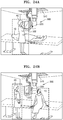
FIGS. 24A and 24B are views for explaining a method performed by the X-ray apparatus ofFIG. 21 to control imaging option settings by recognizing a behavior of a user and a behavior of the object; -
FIG. 25 is a flowchart of the method ofFIGS. 24A and 24B ; and -
FIG. 26 is a block diagram of the X-ray apparatus according to an embodiment. - Certain embodiments are described in greater detail below with reference to the accompanying drawings.
- In the following description, like drawing reference numerals are used for like elements, even in different drawings. The matters defined in the description, such as detailed construction and elements, are provided to assist in a comprehensive understanding of the embodiments. However, it is apparent that the embodiments can be practiced without those specifically defined matters. Also, well-known functions or constructions are not described in detail since they would obscure the description with unnecessary detail.
- The terms used in this specification are those general terms currently widely used in the art in consideration of functions regarding the present disclosure, but the terms may vary according to the intention of those of ordinary skill in the art, precedents, or new technology in the art. Also, specified terms may be selected by the applicant, and in this case, the detailed meaning thereof will be described in the detailed description of the inventive concept. Thus, the terms used in the specification should be understood not as simple names but based on the meaning of the terms and the overall description of the inventive concept.
- Throughout the specification, an "image" may denote multi-dimensional data composed of discrete image elements (for example, pixels in a two-dimensional (2D) image and voxels in a three-dimensional (3D) image). For example, an image may be a medical image of an object acquired by an X-ray apparatus, a computed tomography (CT) apparatus, a magnetic resonance imaging (MRI) apparatus, an ultrasound diagnosis apparatus, or another medical imaging apparatus.
- In addition, an "object" may be a human, an animal, or a part of a human or animal. For example, the object may include an organ (for example, the liver, the heart, the womb, the brain, breasts, or the abdomen), blood vessels, or a combination thereof. The object may be a phantom. The phantom denotes a material having a volume, a density, and an effective atomic number that are approximately the same as those of a living organism. For example, the phantom may be a spherical phantom having similar properties to those of the human body.
- Throughout the specification, a "user" may be, but is not limited to, a medical expert, for example, a medical doctor, a nurse, a medical laboratory technologist, or a medical imaging expert, or a technician who repairs medical apparatuses.
- An X-ray apparatus is a medical imaging apparatus that acquires images of internal structures of an object by transmitting an X-ray through the human body. The X-ray apparatus may acquire medical images of an object more simply within a shorter time than other medical imaging apparatuses including an MRI apparatus and a CT apparatus. Therefore, the X-ray apparatus is widely used in simple chest imaging, simple abdomen imaging, simple skeleton imaging, simple nasal sinuses imaging, simple neck soft tissue imaging, and breast imaging.
-
FIG. 1 is a block diagram of anX-ray system 1000. Referring toFIG. 1 , theX-ray system 1000 includes anX-ray apparatus 100 and aworkstation 110. TheX-ray apparatus 100 shown inFIG. 1 may be a fixed-type X-ray apparatus or a mobile X-ray apparatus. TheX-ray apparatus 100 may include anX-ray emitter 120, ahigh voltage generator 121, adetector 130, e.g., an X-ray detector, amanipulator 140, and acontroller 150, e.g., a microprocessor. Thecontroller 150 may control overall operations of theX-ray apparatus 100. - The
high voltage generator 121 generates a high voltage for generating X-rays, and applies the high voltage to anX-ray source 122, i.e., an X-ray tube. - The
X-ray emitter 120 includes theX-ray source 122 for receiving the high voltage from thehigh voltage generator 121 to generate and radiate an X-ray, and acollimator 123 for guiding a path of the X-ray radiated from theX-ray source 122 and adjusting an irradiation region radiated by the X-ray. - The
X-ray source 122 includes an X-ray tube that may include a vacuum tube diode including a cathode and an anode. An inside of the X-ray tube is set as a high vacuum state of about 10 mmHg, and a filament of the anode is heated to a high temperature to generate thermal electrons. The filament may be a tungsten filament, and a voltage of about 10V and a current of about 3 to 5 A may be applied to an electric wire connected to the filament to heat the filament. - In addition, when a high voltage of about 10 to about 300 kVp is applied between the cathode and the anode, the thermal electrons are accelerated to collide with a target material of the cathode, and then, an X-ray is generated. The X-ray is radiated outside via a window, and the window may be formed of a beryllium thin film. In this case, most of the energy of the electrons colliding with the target material is consumed as heat, and remaining energy is converted into the X-ray.
- The cathode is mainly formed of copper, and the target material is disposed opposite to the anode. The target material may be a high resistive material such as chromium (Cr), iron (Fe), cobalt (Co), nickel (Ni), tungsten (W), or molybdenum (Mo). The target material may be rotated by a rotating field. When the target material is rotated, an electron impact area is increased, and a heat accumulation rate per unit area may be increased to be at least ten times greater than that of a case where the target material is fixed.
- The voltage applied between the cathode and the anode of the X-ray tube is referred to as a tube voltage, and the tube voltage is applied from the
high voltage generator 121 and a magnitude of the tube voltage may be expressed by a crest value (kVp). When the tube voltage increases, a velocity of the thermal electrons increases, and accordingly, an energy of the X-ray (energy of photon) that is generated when the thermal electrons collide with the target material is increased. The current flowing in the X-ray tube is referred to as a tube current that may be expressed as an average value (mA). When the tube current increases, the number of thermal electrons emitted from the filament is increased, and accordingly, the X-ray dose (the number of X-ray photons) generated when the thermal electrons collide with the target material is increased. - Therefore, the energy of the X-ray may be adjusted according to the tube voltage, and the intensity of the X-ray or the X-ray dose may be adjusted according to the tube current and the X-ray exposure time.
- The
detector 130 detects an X-ray that is radiated from theX-ray emitter 120 and is transmitted through an object. Thedetector 130 may be a digital detector. Thedetector 130 may be implemented by using a thin-film transistor (TFT) or a charge-coupled device (CCD). Although thedetector 130 is included in theX-ray apparatus 100 inFIG. 1 , thedetector 130 may be an X-ray detector that is a separate device capable of being connected to or separated from theX-ray apparatus 100. - The
X-ray apparatus 100 may further include themanipulator 140 for providing a user with an interface for manipulating theX-ray apparatus 100. Themanipulator 140 may include anoutput unit 141, e.g., an output transmitter such as a display device or a microphone, and aninput unit 142, e.g., an input receiver. Theinput unit 142 may receive from a user a command for manipulating theX-ray apparatus 100 and various types of information related to X-ray imaging. Thecontroller 150 may control or manipulate theX-ray apparatus 100 according to the information received by theinput unit 142. Theoutput unit 141 may output sound representing information related to a photographing operation such as the X-ray radiation under the control of thecontroller 150. - The
workstation 110 and theX-ray apparatus 100 may be connected to each other by wire or wirelessly. When they are connected to each other wirelessly, a device (not shown) for synchronizing clock signals with each other may be further included. Theworkstation 110 and theX-ray apparatus 100 may exist within physically separate spaces. - The
workstation 110 may include anoutput unit 111, e.g., an output transmitter such as a display device or a microphone, aninput unit 112, e.g., an input receiver, and acontroller 113, e.g., a microprocessor. Theoutput unit 111 and theinput unit 112 provide the user with an interface for manipulating theworkstation 110 and theX-ray apparatus 200. Thecontroller 113 may control theworkstation 110 and theX-ray apparatus 200. - The
X-ray apparatus 100 may be controlled via theworkstation 110 or may be controlled by thecontroller 150 included in theX-ray apparatus 100. Accordingly, the user may control theX-ray apparatus 100 via theworkstation 110 or may control theX-ray apparatus 100 via themanipulator 140 and thecontroller 150 included in theX-ray apparatus 100. In other words, the user may remotely control theX-ray apparatus 100 via theworkstation 110 or may directly control theX-ray apparatus 100. - Although the
controller 113 of theworkstation 110 is separate from thecontroller 150 of theX-ray apparatus 100 inFIG. 1, FIG. 1 is only an example. As another example, thecontrollers workstation 110 and theX-ray apparatus 100. Hereinafter, thecontrollers controller 113 of theworkstation 110 and/or thecontroller 150 of theX-ray apparatus 100. - The
output unit 111 and theinput unit 112 of theworkstation 110 may provide the user with an interface for manipulating theX-ray apparatus 100, and theoutput unit 141 and theinput unit 142 of theX-ray apparatus 100 may also provide the user with an interface for manipulating theX-ray apparatus 100. Although theworkstation 110 and theX-ray radiation apparatus 100 include theoutput units input units FIG. 1 , embodiments are not limited thereto. Only one among theworkstation 110 and theX-ray apparatus 100 may include an output unit or an input unit. - Hereinafter, the
input units input unit 112 of theworkstation 110 and/or theinput unit 142 of theX-ray apparatus 100, and theoutput units output unit 111 of theworkstation 110 and/or theoutput unit 141 of theX-ray apparatus 100. - Examples of the
input units input units input units - In other words, when the user pushes the switch, a prepare command for performing a pre-heating operation for X-ray radiation may be input through the switch, and then, when the user pushes the switch once more, the radiation command for performing substantial X-ray radiation may be input through the switch. When the user manipulates the switch as described above, the
controllers high voltage generator 121 for generating a high voltage for generating the X-ray. - When the
high voltage generator 121 receives the prepare signal from thecontrollers high voltage generator 121 starts a pre-heating operation, and when the pre-heating is finished, thehigh voltage generator 121 outputs a ready signal to thecontrollers detector 130 also needs to prepare to detect the X-ray, and thus thehigh voltage generator 121 performs the pre-heating operation and thecontrollers detector 130 so that thedetector 130 may prepare to detect the X-ray transmitted through the object. Thedetector 130 prepares to detect the X-ray in response to the prepare signal, and when the preparing for the detection is finished, thedetector 130 outputs a ready signal to thecontrollers - When the pre-heating operation of the
high voltage generator 121 is finished and thedetector 130 is ready to detect the X-ray, thecontrollers high voltage generator 121, thehigh voltage generator 121 generates and applies the high voltage to theX-ray source 122, and theX-ray source 122 radiates the X-ray. - When the
controllers high voltage generator 121, thecontrollers output units output units output units FIG. 1 , theoutput unit 141 is included in themanipulator 140; however, embodiments are not limited thereto, and theoutput unit 141 or a portion of theoutput unit 141 may be located elsewhere. For example, theoutput unit 141 may be located on a wall of an examination room in which the X-ray imaging of the object is performed. - The
controllers X-ray emitter 120 and thedetector 130, imaging timing, and imaging conditions, according to imaging conditions set by the user. - In more detail, the
controllers high voltage generator 121 and thedetector 130 according to the command input via theinput units control units detector 130 according to a predetermined imaging condition, and controls operation timing of thedetector 130. - Furthermore, the
controllers detector 130. In detail, thecontrollers detector 130, and then, generate the medical image of the object by removing noise from the image data and adjusting a dynamic range and interleaving of the image data. - The
output units controllers output units X-ray apparatus 100, for example, a user interface (UI), user information, or object information. Examples of theoutput units - The
workstation 110 shown inFIG. 1 may further include a communicator (not shown) that may be connected to aserver 11, amedical apparatus 12, and aportable terminal 13 via anetwork 15. - The communicator may be connected to the
network 15 by wire or wirelessly to communicate with theserver 11, themedical apparatus 164, or the portable terminal 166. The communicator may transmit or receive data related to diagnosis of the object via thenetwork 15, and may also transmit or receive medical images captured by themedical apparatus 164, for example, a CT apparatus, an MRI apparatus, or an X-ray apparatus. Moreover, the communicator may receive a medical history or treatment schedule of the object (e.g., a patient) from theserver 11 to diagnose a disease of the object. Also, the communicator may perform data communication with theportable terminal 13 such as a mobile phone, a personal digital assistant (PDA), or a laptop computer of a medical doctor or a client, as well as theserver 11 or themedical apparatus 164 in a hospital. - The communicator may include one or more elements enabling communication with external apparatuses. For example, the communicator may include a local area communication module, a wired communication module, and a wireless communication module.
- The local area communication module refers to a module for performing local area communication with an apparatus located within a predetermined distance. Examples of local area communication technology may include, but are not limited to, a wireless local area network (LAN), Wi-Fi, Bluetooth, ZigBee, Wi-Fi Direct (WFD), ultra wideband (UWD), infrared data association (IrDA), Bluetooth low energy (BLE), and near field communication (NFC).
- The wired communication module refers to a module for communicating by using an electrical signal or an optical signal. Examples of wired communication technology may include wired communication techniques using a pair cable, a coaxial cable, and an optical fiber cable, and other wired communication techniques that are known to one skilled in the art.
- The wireless communication module transmits and receives a wireless signal to and from at least one selected from a base station, an external apparatus, and a server in a mobile communication network. Here, examples of the wireless signal may include a voice call signal, a video call signal, and various types of data according to text/multimedia messages transmission.
- The
X-ray apparatus 100 shown inFIG. 1 may include a plurality of digital signal processors (DSPs), an ultra-small calculator, and a processing circuit for special purposes (for example, high speed analog/digital (A/D) conversion, high speed Fourier transformation, and an array process). - In addition, communication between the
workstation 110 and theX-ray apparatus 100 may be performed using a high speed digital interface, such as low voltage differential signaling (LVDS), asynchronous serial communication, such as a universal asynchronous receiver transmitter (UART), a low latency network protocol, such as error synchronous serial communication or a controller area network (CAN), or any of various other communication methods that are known to one skilled in the art. -
FIG. 2 is a conceptual view for explaining a method performed by theX-ray system 1000 to generate an image marker according to an embodiment. - Referring to
FIG. 2 , theX-ray system 1000 may include theX-ray apparatus 100 and theworkstation 110. TheX-ray apparatus 100 may include theX-ray emitter 120 that radiates X-rays to anobject 10, thedetector 130 that detects X-rays radiated from theX-ray emitter 120 and transmitted through theobject 10, themanipulator 140 that provides a user interface (UI) for manipulating theX-ray apparatus 100, and animage obtainer 160 that is attached to a side of theX-ray emitter 120 and photographs theobject 10. - The
image obtainer 160 may obtain a plurality of still images of theobject 10 by continuously photographing theobject 10. The plurality of still images that are images obtained by theimage obtainer 160 through photographing are different from an X-ray image that is obtained by x-ray imaging theobject 10. Theimage obtainer 160 may be a camera that is a general apparatus for obtaining an image. Theimage obtainer 160 may include at least one of, for example, a complementary metal-oxide-semiconductor (CMOS) module, a CCD module, and an apparatus for taking a video. Theimage obtainer 160 may be attached to a side of the collimator 123 (seeFIG. 1 ) of theX-ray emitter 120. - The
workstation 110 may include theoutput unit 111 and thecontroller 113. Thecontroller 113 may be connected to theX-ray apparatus 100 by wire or wirelessly. Although thecontroller 113 is included in theworkstation 110 inFIG. 2 , embodiments are not limited thereto. In an embodiment, theworkstation 110 may be included in theX-ray apparatus 100. - The
controller 113 may select a representative still image that represents a body part of theobject 10 to be X-ray imaged (hereinafter, referred to as a to-be-X-ray imaged or candidate body part of the object 10) among the plurality of still images obtained by theimage obtainer 160 by continuously photographing theobject 10, and may generate theimage marker 180 by performing image processing on the selected representative still image. TheX-ray apparatus 100 may detect X-rays radiated to theobject 10 from theX-ray emitter 120 and transmitted through theobject 10 by using thedetector 130, and thecontroller 113 of theworkstation 110 may receive image data through thedetector 130 and may obtain anX-ray image 170 of theobject 10 by performing image processing on the received image data. In an embodiment, thecontroller 113 may display theimage marker 180 so that theimage marker 180 overlaps a first region of theX-ray image 170. - The
output unit 111 of theworkstation 110 may display theimage marker 180 along with theX-ray image 170 by causing theimage marker 180 to overlap theX-ray image 170. In an embodiment, theX-ray image 170 and theimage marker 180 may also be displayed on themanipulator 140 of theX-ray apparatus 100. - In general, the X-ray imaging is performed by imaging various body parts of the
object 10 in a given imaging direction for diagnostic purposes. In this case, examples of the imaging direction may include an antero-posterior (AP) direction in which theobject 10 is imaged from front to back, a postero-anterior (PA) direction in which the object is imaged from back to front, a lateral right/left (R/L) direction in which theobject 10 is laterally imaged, and an oblique R/L direction in which theobject 10 is obliquely imaged. TheX-ray image 170 captured by a user of theX-ray system 1000, for example, a radiologist, may be oriented or flipped before being transmitted to an examining doctor. In this case, a marker that may be observed by the examining doctor is needed. However, when a marker that is preset in theX-ray system 1000 is different from an actual imaging condition or the radiologist makes a mistake, a wrong marker may be used, thereby leading to a medical mistake or malpractice. - The
X-ray system 1000 according to an embodiment may generate a still image, obtained by theimage obtainer 160 by photographing theobject 10, as theimage marker 180 and may display theimage marker 180 so that theimage marker 180 overlaps theX-ray image 170. Since theX-ray system 1000 according to an embodiment photographs an appearance of theobject 10 at a photographing time and directly uses a still image of theobject 10 as an image marker, the user (e.g., a radiologist or an examining doctor) may easily recognize and determine whether theX-ray image 170 has been captured in a normal imaging direction, has been flipped, or in particular, has been vertically or horizontally flipped. Accordingly, a medical malpractice which occurs when the user, in particular, the examining doctor, fails to detect whether theX-ray image 170 is vertically or horizontally flipped and mistakenly diagnoses a disease of theobject 10, may be prevented in advance. -
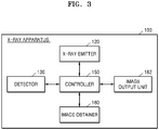
FIG. 3 is a block diagram of theX-ray apparatus 100 according to an embodiment. - Referring to
FIG. 3 , theX-ray apparatus 100 may include theX-ray emitter 120, thedetector 130, thecontroller 150, theimage obtainer 160, and animage output unit 162. TheX-ray emitter 120 and thedetector 130 are the same as those inFIGS. 1 and2 , and thus a repeated explanation thereof will not be provided. - The
image obtainer 160 may include a camera attached to a side of the X-ray emitter 120 (seeFIG. 2 ). The camera may be disposed to face the object 10 (seeFIG. 2 ) and may include a camera sensor configured to convert an image of theobject 10 into an electrical signal and a signal processor configured to convert an analog image signal transmitted from the camera sensor into digital data. The camera sensor may be a CCD or CMOS sensor, and the signal processor may be a DSP. The camera sensor may photograph theobject 10 and the signal processor may obtain a captured image of theobject 10. In an embodiment, the camera sensor may continuously photograph theobject 10 and the signal processor may obtain a plurality of still images of theobject 10. - The
controller 150 may select one from the plurality of still images of theobject 10 obtained by theimage obtainer 160 and may generate the selected still image as a representative still image. The representative still image may be a still image that represents a candidate body part of theobject 10. - The
controller 150 may generate the image marker 180 (seeFIG. 2 ) by performing image processing on a captured image of theobject 10. In an embodiment, thecontroller 150 may perform image processing on the representative still image selected from the plurality of still images obtained by theimage obtainer 160 by photographing theobject 10 and may generate the image-processed representative still image as theimage marker 180. In an embodiment, thecontroller 150 may generate the representative still image itself as theimage marker 180. However, embodiments are not limited thereto, and thecontroller 150 may generate theimage marker 180 by using image processing that blurs and/or mosaics the representative still image. Also, thecontroller 150 may generate the X-ray image 170 (seeFIG. 2 ) of theobject 10 and may cause theimage marker 180 to overlap the generatedX-ray image 170. In an embodiment, thecontroller 150 may cause theimage marker 180 to overlap a first region in theX-ray image 170 by reducing a size of theimage marker 180 to be less than that of theX-ray image 170. - The
controller 150 may include a hardware element such as a field-programmable gate array (FPGA) or an application-specific integrated circuit (ASIC). For example, thecontroller 150 may be a hardware device including at least one among hardware units including a central processing unit (CPU), a microprocessor, a graphics processing unit (GPU), and a memory - The
controller 150 may control theX-ray image 170 and theimage marker 180 to be displayed on theimage output unit 162. In an embodiment, thecontroller 150 may store theimage marker 180 in a digital imaging and communications in medicine (DICOM) header, instead of simultaneously displaying theimage marker 180 and theX-ray image 170. Once theimage marker 180 is stored in the DICOM header, thecontroller 150 may determine whether to display theimage marker 180 according to option settings of the user. - The
image output unit 162 may display theX-ray image 170 which theimage marker 180 overlaps to the user. Theimage marker 180 may be displayed so that theimage marker 180 overlaps the first region of theX-ray image 170. - In an embodiment, the
image output unit 162 may display a UI for manipulating theX-ray apparatus 100 by using the X-ray image 17 and theimage marker 180. When theimage output unit 162 displays theX-ray image 170, theimage marker 180, and the UI, theimage output unit 162 may be a touch screen for receiving a touch input of the user. -
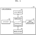
FIG. 4 is a block diagram of an X-ray apparatus 100' according to an embodiment. - Referring to
FIG. 4 , the X-ray apparatus 100' may include theworkstation 110, theX-ray emitter 120, thedetector 130, theimage obtainer 160, and theimage output unit 162. TheX-ray emitter 120, thedetector 130, theimage obtainer 160, and theimage output unit 162 ofFIG. 4 are the same as those inFIG. 3 , and thus a repeated explanation thereof will not be provided. - The
workstation 110 may include thecontroller 113. Thecontroller 113 may generate the image marker 180 (seeFIG. 2 ) by performing image processing on a captured image of theobject 10 obtained by theimage obtainer 160. Also, thecontroller 113 may generate the X-ray image 170 (seeFIG. 2 ) of theobject 10 based on X-rays detected by thedetector 130, and may cause theimage marker 180 to overlap the generatedX-ray image 170. - In any embodiment of the specification, the
controller 113 may perform the same function and operation as that of thecontroller 150 ofFIG. 3 , and thus a repeated explanation thereof will not be provided. -
FIG. 5 is a flowchart of a method performed by the X-ray apparatus ofFIG. 3 to generate theimage marker 180. - In operation S501, the X-ray apparatus obtains a captured image of an object by continuously photographing the object and selects a representative still image that represents a candidate body part of the object. In an embodiment, the X-ray apparatus may obtain a plurality of still images of the object by continuously photographing the object. The captured image of the object may be different from an X-ray image obtained by X-ray imaging the object. The plurality of still images may be obtained by a camera for obtaining an image. In an embodiment, the image obtainer 160 (see FIG. and 3) may obtain a plurality of still images of the object 10 (see
FIG. 2 ) by continuously photographing theobject 10. - The X-ray apparatus may select a representative still image that represents a candidate body part of the object from among the plurality of still images. In an embodiment, the X-ray apparatus may recognize an image that is clearly captured because a camera is accurately focused on the candidate body part of the object by performing image processing on all of the plurality of still images and may determine the recognized image as a representative still image.
- In operation S502, the X-ray apparatus generates an image marker by performing image processing on the captured image. In an embodiment, the image marker may be generated by using image processing that blurs or mosaics the captured image. In an embodiment, a shape of the object included in the captured image is recognized by performing image processing on the captured image, and the image marker may be a cartoon image similar to the recognized shape. However, embodiments are not limited thereto, and the image marker may be the captured image itself, or may include the same image as the captured image. In an embodiment, the
controller 150 or 113 (seeFIG. 3 ) may generate the image marker by performing image processing on a representative still image among the plurality of still images of the object. - In operation S503, the X-ray apparatus combines the image marker with an X-ray image of the object. In an embodiment, a size of the image marker may be less than a size of the X-ray image. In an embodiment, the
controller 150 or 113 (seeFIG. 3 ) may combine the image marker with the X-ray image so that the image marker overlaps a first region in the X-ray image. -
FIGS. 6A through 6C are views for explaining a method of correcting a still image of an object according to an embodiment. - Referring to
FIG. 6A , a first representative stillimage 181 is vertically flipped to generate a first corrected image 181'. The first corrected image 181' may be an image in which theobject 10 included in the first representative stillimage 181 is vertically flipped. In an embodiment ofFIG. 6A , a target body part of theobject 10 may be the chest of a patient, and the first representative stillimage 181 may be an image with thehead 12 of theobject 10 upside down. In an embodiment, the controller 150 (seeFIG. 3 ) may recognize thehead 12 of the patient included in the first representative stillimage 181 and may vertically flip the first representative still image 181 so that thehead 12 of the patient is on an upper side. Since the first corrected image 181' is generated by correcting thehead 12 of the patient included in the first representative stillimage 181 to be on the upper side, a user may intuitively recognize a direction of the patient, that is, theobject 10. - Referring to
FIG. 6B , a second representative stillimage 182 may be vertically flipped, like the first representative stillimage 181. In an embodiment ofFIG. 6B , a target body part of anobject 11 may be the hand of a patient, and the second representative stillimage 182 may be vertically flipped so that fingers are on an upper side to obtain a second corrected image 182'. In an embodiment, when theobject 11 included in the second representative stillimage 182 is not located at a central portion of the second representative stillimage 182, the second corrected image 182' may be generated by correcting a position of theobject 11. The controller 150 (seeFIG. 3 ) may generate the second corrected image 182' by correcting a direction and/or a position of the second representative stillimage 182. - Referring to
FIG. 6C , a third representative stillimage 183 may be horizontally flipped to generate a third corrected image 183'. The third corrected image 183' may be an image in which theobject 10 included in the third representative stillimage 183 is horizontally flipped. In an embodiment ofFIG. 6C , although a target body part of theobject 10 includes the right side of the chest and the right shoulder of the patient and the right side of the chest and the right shoulder of theobject 10 were actually X-ray imaged, if a user (e.g., an examining doctor) recognizes as if the left side of the chest and the left shoulder are X-ray imaged, the third corrected image 183' may be generated by flipping the third representative stillimage 183 for better intuitive understanding of the user. In an embodiment, a symbol such as a left right arrow indicating a horizontal flip may be displayed on the third corrected image 183'. Also, a text or a word, e.g., a word "Flip" indicating that an image is horizontally flipped may be displayed on the third corrected image 183'. However, embodiments are not limited thereto, and although not shown inFIG. 6C , the third corrected image 183' may include a text or a word, e.g., a letter "R" to indicate that an image is obtained by photographing the right side of the chest and the right shoulder of theobject 10. - Referring back to
FIG. 3 , the controller 150 (seeFIG. 3 ), the image obtainer 160 (seeFIG. 3 ) may select a representative still image that represents a candidate body part of an object among a plurality of still images of the object obtained by the image obtainer 160 (seeFIG. 3 ) by continuously photographing the object. Thecontroller 150 may select a still image that is obtained immediately before X-ray imaging among the plurality of still images as a representative still image. In an embodiment, thecontroller 150 may recognize an image that is clearly captured because a camera is accurately focused on the candidate body part of the object by performing image processing on all of the plurality of still images, and may determine the recognized image as a representative still image. In an embodiment, thecontroller 150 may recognize an image whose candidate body part of the object is the brightest by performing image processing on all of the plurality of still images, and may determine the recognized image as a representative still image. - The
controller 150 may also correct a direction and/or a position of the representative still image. In an embodiment, thecontroller 150 may recognize the object included in the representative still image by performing image processing on the representative still image and may recognize direction information and/or position information of the object. Thecontroller 150 may also correct the representative still image based on the recognized direction information and/or the recognized position information. In an embodiment, thecontroller 150 may perform pre-processing by adjusting a brightness or a dynamic range of the representative still image. In an embodiment, thecontroller 150 may correct a direction and/or a position of the representative still image by using direction and position information preset in theX-ray apparatus 100 or theworkstation 110. However, embodiments are not limited thereto, and thecontroller 150 may correct a direction and/or a position of the representative still image by using geometric information of a system and an image processing algorithm. - The
controller 150 may generate an image marker by performing image processing on the representative still image. Thecontroller 150 may blur or mosaic the representative still image and may generate the blurred or mosaic-processed representative still image as an image maker. Thecontroller 150 may recognize an outline or a shape of the object included in the representative still image by performing image processing on the representative still image and may generate a cartoon image having the recognized outline or the recognized shape as an image marker. -
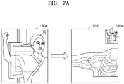
FIGS. 7A through 7D are views for explaining an image processing method of generating an image marker by using a representative still image according to an embodiment. - Referring to
FIG. 7A , a representative still image itself may be animage marker 180a without performing additional image processing on the representative still image. Theimage maker 180a may overlap a first region of theX-ray image 170. In an embodiment ofFIG. 7A , since the representative still image that is obtained by photographing a patient whose right side of the chest and right shoulder are being X-ray imaged is theimage marker 180a, a user (in this case, an examining doctor) may intuitively know how which body part of the patient has been X-ray imaged when interpreting an X-ray image. - Referring to
FIG. 7B , a representativestill image 180b' may be blurred and may be generated as animage marker 180b. An outline and a shape of theobject 10 included in the representative stillimage 180b' may be blurred so that only minimum information such as a position of theobject 10 on thedetector 130 or a candidate body part may be recognized. Theimage maker 180b that is blurred may overlap the first region of theX-ray image 170 and may be displayed along with theX-ray image 170. - Referring to
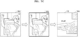
FIG. 7C , a representativestill image 180c' may be mosaic-processed and may be generated as animage maker 180c. Like inFIG. 7B , an outline and a shape of theobject 10 included in the representative stillimage 180c' may be mosaic-processed so that only a candidate body part of theobject 10 and a position of the candidate body part are recognized. Theimage marker 180c that is mosaic-processed may overlap the first region of theX-ray image 170 and may be displayed along with theX-ray image 170. - In an embodiment of
FIG. 7B or7C , the representative stillimage 180b' or 180c' is blurred or mosaic-processed so that a user (e.g., a radiologist or an examining doctor) does not recognize a captured image of theobject 10, that is, a patient, included in the representative stillimage 180b' or 180c'. This is to prevent the risk of the patient's privacy invasion. In detail, when the patient does not want to expose body parts other than a candidate body part or the patient's body secret may be possibly exposed, a captured image of the patient including the candidate body part may be blurred or mosaic-processed, to prevent the risk of privacy invasion. - Referring to
FIG. 7D , a representative stillimage 180d' may be replaced with a cartoon image and the cartoon image may be animage marker 180d. In an embodiment, a cartoon image may be generated by performing image processing that simply illustrates an outline and a shape of theobject 10, included in the representative stillimage 180d', with only lines and surface and may be theimage marker 180d. In an embodiment, an outline and a shape of theobject 10 included in the representative stillimage 180d may be recognized by performing image processing on the representative stillimage 180d', the recognized outline and the recognized shape of theobject 10 may be compared with images pre-stored in a storage such as a database to select a most similar cartoon image, the most similar cartoon image may be theimage marker 180d, and theimage marker 180d may overlap theX-ray image 170. In an embodiment ofFIG. 7D , since a captured image of theobject 10, that is, a patient, included in the representative stillimage 180d', is changed into a cartoon image by performing image processing on the captured image, the risk of the patient's privacy invasion may be prevented, like inFIGS. 7B and7C . -
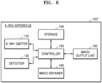
FIG. 8 is a block diagram of anX-ray apparatus 100" according to an embodiment. Referring toFIG. 8 , theX-ray apparatus 100" may include theX-ray emitter 120, thedetector 130, thecontroller 150, theimage obtainer 160, theimage output unit 162, and astorage 164. TheX-ray emitter 120, thedetector 130, theimage obtainer 160, and theimage output unit 162 are the same as those inFIG. 3 , and thus a repeated explanation thereof will not be provided. - The
controller 150 may select a representative still image among a plurality of still images obtained by theimage obtainer 160 by continuously photographing an object, and may generate an image marker by performing image processing such as blurring, mosaic processing, and cartoon imaging on the representative still image. In an embodiment, thecontroller 150 may generate the representative still image itself as an image marker without performing additional image processing on the representative still image. The reason why thecontroller 150 performs image processing on the representative still image so that a user (e.g., a radiologist or an examining doctor) might not recognize an outline or a shape of the object is that the risk of a patient's privacy invasion is prevented as described with reference toFIGS. 7B through 7D . In an embodiment, thecontroller 150 may select any one among blurring, mosaic processing, and cartoon imaging as image processing according to option settings of theX-ray apparatus 100". - The
storage 164 may store cartoon images or object sample images that may replace the representative still image. In an embodiment, thestorage 164 may include at least one among a volatile memory (e.g., a dynamic random-access memory (DRAM), a static RAM (SRAM), or a synchronous dynamic RAM (SDRAM)), a nonvolatile memory (e.g., a one-time programmable ROM (OTPROM), a programmable ROM (PROM), an erasable and programmable ROM (EPROM), an electrically erasable and programmable ROM (EEPROM), a mask ROM, or a flash ROM), a hard disk drive (HDD), and a solid-state drive (SSD). In an embodiment, thestorage 164 may include a database. - The
controller 150 may recognize an outline and a shape of the object included in the representative still image by performing image processing on the representative still image, and may compare the recognized outline and the recognized shape of the object with the cartoon images or the object sample images stored in thestorage 164. Thecontroller 150 may select an image that is most similar to the object included in the representative still image among the cartoon images or the object sample images stored in thestorage 164 and may generate an image marker by using the selected image. In an embodiment, thecontroller 150 may cause the generated image marker to overlap an X-ray image and may display the image marker along with the X-ray image. -
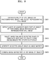
FIG. 9 is a flowchart of a method performed by theX-ray apparatus 100" ofFIG. 8 to generate an image marker. - In operation S901, an X-ray apparatus obtains a plurality of still images by continuously photographing an object, and selects a representative still image that represents a candidate body part of the object among the plurality of still images. The representative still image may be a still image obtained by photographing the candidate body part of the object among still images obtained immediately before X-ray imaging among the plurality of still images. The obtaining of the plurality of still images and the selecting of the representative still image are the same as those described in operation S501 of
FIG. 5 , and thus a repeated explanation thereof will not be provided. - In operation S902, a shape of the candidate body part of the object is recognized by performing image processing on the representative still image. The X-ray apparatus may recognize an outline and a shape of the object included in the representative still image by performing image processing on the representative still image. In an embodiment, the controller 150 (see
FIG. 8 ) may recognize the object included in the representative still image by using one of image recognition techniques known in the art. - In operation S903, an image that is similar to the recognized shape of the candidate body part of the object is selected among images pre-stored in a storage. In an embodiment, the controller 150 (see
FIG. 8 ) may recognize an outline and a shape of the candidate body part of the object included in the representative still image by using image recognition, and may compare the recognized outline and the recognized shape of the object with images pre-stored in the storage 164 (seeFIG. 8 ). Also, thecontroller 150 may compare the recognized outline and the recognized shape of the object with cartoon images and/or object sample images stored in thestorage 164, and may select an image that is most similar to the recognized outline and the recognized shape of the object among the cartoon images and/or the object sample images. Thestorage 164 may be a memory included in theworkstation 110. However, embodiments are not limited thereto, and thestorage 164 may be an external database. - In operation S904, the selected similar image is generated as an image marker. In an embodiment, the controller 150 (see
FIG. 8 ) may generate an image marker by using a cartoon image or an object sample image selected in operation S903. - In operation S905, the image marker is combined with an X-ray image. The image marker combined with the X-ray image may overlap the X-ray image and may be output together with the X-ray image on the image output unit 162 (see
FIG. 8 ) or the output unit 111 (seeFIG. 2 ) of theworkstation 110. However, embodiments are not limited thereto, and the image marker may be stored in a DICOM header, instead of or in addition to being displayed on theimage output unit 162 or theoutput unit 111 based on display option settings of a user.FIG. 10 shows theX-ray image 170 including theimage marker 180 and aguide image 190 according to an embodiment. - Referring to
FIG. 10 , theimage marker 180 may be formed on a region of theX-ray image 170, and theguide image 190 may be included in theimage marker 180. Theguide image 190 may be an image that enables a user to recognize a vertical/horizontal direction of theimage marker 180. In an embodiment, theguide image 190 may be a figure image or a cartoon image including text and/or an arrow. - In an embodiment of
FIG. 10 , theguide image 190 may be a cartoon image. Since theguide image 190 is displayed along with theimage marker 180 on a region of theimage marker 180, the user (e.g., an examining doctor) may easily recognize in what shape theobject 10 is X-ray imaged by using the left and right sides of theimage marker 180. In an embodiment, theguide image 190 may be displayed as at least one among an arrow, a figure, and a word, e.g., a word "Flip," indicating that theX-ray image 170 is horizontally flipped on theimage marker 180. - Referring back to
FIG. 3 , the controller 150 (seeFIG. 3 ) may select a representative still image that represents a candidate body part among a plurality of still images of an object obtained by theimage obtainer 160 by continuously photographing the object, and may generate an image marker by performing image processing on the selected representative still image. In an embodiment, thecontroller 150 may blur or mosaic the representative still image, and may generate the blurred or mosaic-processed representative still image as an image marker. - The
controller 150 may generate a guide image that enables a user to recognize an X-ray imaging direction of the object included in the image marker. In an embodiment, the guide image may be at least one among a text, an arrow, and a figure image that enables the user to recognize a vertical or horizontal direction of the image marker. In an embodiment, thecontroller 150 may perform image processing on the image marker to generate a cartoon image, and may generate a guide image by using the cartoon image. Thecontroller 150 may generate a cartoon image by using image recognition that recognizes an outline and a shape of an image of the object included in the image marker. However, embodiments are not limited thereto, and thecontroller 150 may generate a guide image including an arrow or a text, e.g., a word "Flip," that enables the user to recognize whether the image marker is horizontally flipped. -
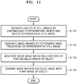
FIG. 11 is a flowchart of a method performed by theX-ray apparatus 100 ofFIG. 3 to generate an image marker including a guide image. - In operation S1101, an X-ray apparatus obtains a plurality of still images by continuously photographing an object, and selects a representative still image among the obtained plurality of still images of the object. The obtaining of the plurality of still images and the selecting of the representative still image are the same as those described in operation S501 of
FIG. 5 , and thus a repeated explanation thereof will not be provided. - In operation S1102, an image marker is generated by performing image processing on the representative still image. In an embodiment, the image marker may be an image obtained by blurring or mosaic processing the representative still image. The generating of the image marker is the same as that described in operation S502 of
FIG. 5 , and thus a repeated explanation thereof will not be provided. - In operation S1103, the X-ray apparatus generates a guide image indicating a direction or position relationship of the object. In an embodiment, the
controller 150 included in theworkstation 110 may perform image processing on the image marker generated in operation S1102 to obtain a cartoon image, and may generate a guide image by using the cartoon image. However, the guide image is not limited to a cartoon image, and may be at least one among a text, an arrow, and a figure image that enables a user to recognize a vertical/horizontal direction of the image marker. - In operation S1105, the X-ray apparatus combines the image marker and the guide image with an X-ray image of the object. The guide image may be combined to overlap a region of the image marker. The image marker combined with the guide image may overlap a region of the X-ray image obtained by X-ray imaging the object and may be simultaneously displayed along with the X-ray image.
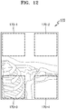
FIG. 12 is a view for explaining a method of determining a position of an image marker according to an embodiment. - Referring to
FIG. 12 , theX-ray image 170 obtained by X-ray imaging an object may include a first region 170-1 through a fourth region 170-4. In an embodiment ofFIG. 12 , a target body part of the object may be the right side of the chest and the right shoulder of a patient. Although the X-ray image of the object is divided into the first region 170-1 through the fourth region 170-4 according to regions inFIG. 12 , embodiments are not limited thereto. Alternatively, theX-ray image 170 may be divided into less or more regions, instead of four regions. - In an embodiment, the first region 170-1 and the second region 170-2 may include clinical information about the object that is less than that of the third region 170-3 and the fourth region 170-4. An image marker may overlap the first region 170-1 or the second region 170-2 including relatively minor clinical information of the object. Accordingly, when the image marker overlaps the
X-ray image 170 and is simultaneously displayed along with theX-ray image 170, a user may obtain sufficient clinical information of the object displayed on theX-ray image 170. However, embodiments are not limited thereto, and the image marker may automatically overlap a region preset in an X-ray apparatus and may be displayed. - Referring back to
FIG. 3 , the controller 150 (seeFIG. 3 ) may select a representative still image that represents a candidate body part among a plurality of still images of an object obtained by theimage obtainer 160 by continuously photographing the object, and may generate an image marker by performing image processing on the selected representative still image. Thecontroller 150 may determine a region which the image marker overlaps in an X-ray image. In an embodiment, thecontroller 150 may determine a position of the image marker that overlaps in the X-ray image based on preset information according to an imaging protocol or the candidate body part of the object. - In an embodiment, the
controller 150 may detect a region including relatively minor clinical information of the object in the X-ray image by performing image processing on the X-ray image obtained by X-ray imaging the object, and may cause the image marker to overlap the detected region. For example, thecontroller 150 may determine a position of the image marker so that the image marker overlaps a background portion or a corner portion of the X-ray image that has insubstantial clinical information.FIG. 13 is a flowchart of a method performed by theX-ray apparatus 100 ofFIG. 3 to determine a position of an image marker. - In operation S1301, an X-ray apparatus obtains a plurality of still images by continuously photographing an object and selects a representative still image. The obtaining of the plurality of still images and the selecting of the representative still image are the same as those described in operation S501 of
FIG. 5 , and thus a repeated explanation thereof will not be provided. - In operation S1302, an image marker is generated by performing image processing on the representative still image. In an embodiment, the image marker may be obtained by blurring or mosaic processing the representative still image. The generating of the image marker is the same as that described in operation S502 of
FIG. 5 , and thus a repeated explanation thereof will not be provided. - In operation S1303, the X-ray apparatus obtains an X-ray image of the object and detects clinical information by performing image processing on the X-ray image. The X-ray apparatus may recognize the object included in the X-ray image by using image recognition and may detect clinical information about the object. In an embodiment, the controller 150 (see
FIG. 3 ) may divide the X-ray image into an arbitrary number of regions and may recognize an amount of clinical information of the object included in each of the arbitrary number of regions. Also, thecontroller 150 may detect a region including a least amount of clinical information among the arbitrary number of regions. - In operation S1304, the X-ray apparatus determines a region whose clinical information in the X-ray image is not detected as a first region. However, embodiments are not limited thereto. In an embodiment, the
controller 150 may determine the region including the least amount of clinical information of the object among the arbitrary number of regions detected in operation S1304 as a first region. - In operation S1305, the X-ray apparatus combines the image marker with the first region. The X-ray apparatus may display the image marker so that the image marker overlaps the first region of the X-ray image of the object.
FIG. 14 is a conceptual view for explaining a method of adjusting positions of mechanical devices of anX-ray apparatus 200 according to an embodiment. - Referring to
FIG. 14 , theX-ray apparatus 200 may include anX-ray emitter 220 that generates X-rays and radiates the X-rays to theobject 10, anX-ray detector 230 that detects X-rays transmitted through theobject 10, animage obtainer 260 that photographs theobject 10 and obtains a captured image of theobject 10, and amanipulator 270 that provides an interface for manipulating theX-ray apparatus 200. TheX-ray emitter 220 and theX-ray detector 230 are respectively the same as theX-ray emitter 120 and thedetector 130 ofFIG. 1 , and thus a repeated explanation thereof will not be provided. - The
X-ray apparatus 200 may include motors each for applying a driving force for moving theX-ray emitter 220, and afirst guide rail 211, asecond guide rail 212, amovable carriage 213, and apost frame 214 that are provided to move theX-ray emitter 220 by using the driving forces of the respective third motors. - The
first guide rail 211 and thesecond guide rail 212 are connected to intersect each other. Thesecond guide rail 212 may be provided on the ceiling of an examination room. Thefirst guide rail 211 may be disposed under thesecond guide rail 212, and may be slidably mounted on thesecond guide rail 212. A roller (not shown) that may move along thesecond guide rail 212 may be provided on thefirst guide rail 211. Thefirst guide rail 211 may be connected to the roller and may move along thesecond guide rail 212. A first direction D1 is defined as a direction in which thefirst guide rail 211 extends, and a second direction D2 is defined as a direction in which thesecond guide rail 212 extends. Accordingly, the first direction D1 and the second direction D2 may intersect each other and may be parallel to the ceiling of the examination room. - The
movable carriage 213 may be disposed under thefirst guide rail 211 to move along thefirst guide rail 211. A roller (not shown) that moves along thefirst guide rail 211 may be provided on themovable carriage 213. Accordingly, themovable carriage 213 may move in the first direction D1 along thefirst guide rail 211, and may move in the second direction D2 along thesecond guide rail 212. - The
post frame 214 may be fixed to themovable carriage 213 and may be disposed under themovable carriage 213. In a state where thepost frame 214 is fixed to themovable carriage 213, a length of thepost frame 214 may be increased or reduced in a third direction D3. The third direction D3 may intersect both the first direction D1 and the second direction D2. - The
X-ray emitter 220 is rotatably provided on a plane that is perpendicular to the ceiling of the examination room. A motor for moving theX-ray emitter 120 in each of the first through third directions D1 through D3 may be provided. The motor may be electrically driven, and may include an encoder. - The
image obtainer 260 may be attached to a side of theX-ray emitter 220. Theimage obtainer 260 may obtain a captured image of theobject 10 by photographing theobject 10. The captured image of theobject 10 obtained by theimage obtainer 260 is different from an X-ray image obtained by X-ray imaging theobject 10. Theimage obtainer 260 may be a camera for obtaining an image. In an embodiment, theimage obtainer 260 may be attached to a side of a collimator 224 (seeFIG. 20 ) of theX-ray emitter 220. - The
manipulator 270 may be provided on a side surface of theX-ray emitter 220. Theemitter 270 may include adisplay 271 and aninput unit 272. - Although the
X-ray apparatus 200 is a fixed X-ray apparatus connected to the ceiling of the examination room inFIG. 14 , this is just for better understanding and embodiments are not limited to the fixed X-ray apparatus. Examples of theX-ray apparatus 200 may include various X-ray apparatuses, such as a C-arm X-ray apparatus and an angiography X-ray apparatus. - In an embodiment of
FIG. 14 , theX-ray apparatus 200 may control a position of theX-ray emitter 220 by performing image processing on a captured image of theobject 10. In detail, theimage obtainer 260 may obtain a captured image of theobject 10 by photographing theobject 10, and theX-ray apparatus 200 may recognize a region of theobject 10 to be X-ray imaged (hereinafter, referred to as a candidate region of the object 10) and a central point of theobject 10 by performing image processing on the obtained captured image, and may control an irradiation region shape of theX-ray emitter 220 and a position of theX-ray emitter 220 so that the recognized candidate region and the recognized central point of theobject 10 are matched to an irradiation region of theX-ray emitter 220 and a central point of theX-ray emitter 220. In an embodiment, theX-ray apparatus 200 may display on the display 271 a UI for displaying information about the irradiation region of theX-ray emitter 220 and the central point of theX-ray emitter 220 to overlap the captured image. In an embodiment, the information about the irradiation region of theX-ray emitter 220 and the central point of theX-ray emitter 220 may be a plurality of combinations of information, and each of the plurality of combinations of information may overlap the captured image to form a plurality of thumbnail images, for example, first through fourth thumbnail images 270-1 through 270-4. The first through fourth thumbnail images 270-1 through 270-4 may be displayed on thedisplay 271. - In an embodiment of
FIG. 14 , since theobject 10 is photographed by using theimage obtainer 260, that is, a camera, to obtain a captured image, a guide UI for controlling an irradiation region and a position of theX-ray emitter 220 is provided by performing image processing on the obtained captured image, and theX-ray emitter 220 is controlled according to an X-ray irradiation region and a position selected by a user (e.g., a radiologist or an examining doctor), a time taken to perform X-ray imaging may be minimized. Also, since theX-ray apparatus 200 according to an embodiment may reduce problems caused when a mechanical device is so heavy that the user feels pain in the shoulder or when the user has to manipulate a mechanical device whenever photographing is performed, photographing efficiency may be improved. Also, since theX-ray apparatus 200 according to an embodiment may control a position and an X-ray irradiation region of theX-ray emitter 220, the quality of an X-ray image may be improved. - A method of controlling an irradiation region and a position of the
X-ray emitter 220 and a method of providing a guide UI in an image processing method ofFIG. 14 will now be explained in detail with reference toFIGS. 15 through 19D . -
FIG. 15 is a flowchart of a method performed by theX-ray apparatus 200 ofFIG. 14 to adjust a position of theX-ray emitter 220. - In operation S1501, the X-ray apparatus 200 (see
FIG. 14 ) obtains a captured image of theobject 10 by photographing theobject 10. In an embodiment, theX-ray apparatus 200 may obtain a plurality of still images of theobject 10 by continuously photographing theobject 10. The captured image of theobject 10 may be different from an X-ray image obtained by X-ray imaging theobject 10. In an embodiment, theimage obtainer 260 may determine only a region on the detector 230 (seeFIG. 14 ), not theentire object 10, as a region of interest (ROI) and may photograph only a body part of theobject 10 corresponding to the ROI. - In operation S1502, the
X-ray apparatus 200 detects a candidate region of theobject 10 and a central point of theobject 10 by performing image processing on the captured image of theobject 10. In an embodiment, theX-ray apparatus 200 may detect a candidate region of theobject 10 and a central point of theobject 10 by using any appropriate image analysis or image recognition algorithm. In an embodiment, theX-ray apparatus 200 may define a portion included in the ROI in the detector 230 (seeFIG. 6 ) as a candidate region, and may detect a central point of a body part of the object included in the ROI. In an embodiment, the candidate region of theobject 10 and the central point of theobject 10 may overlap the captured image as a virtual graphical UI, and may be displayed on the display 271 (seeFIG. 14 ). - In operation S1503, positions of an X-ray irradiation region of a collimator 224 (see
FIG. 20 ) and a central point of an X-ray tube 222 (seeFIG. 20 ) are calculated based on the candidate region of theobject 10 and the central point of theobject 10. In an embodiment, theX-ray apparatus 200 may calculate position values for respectively matching the X-ray irradiation region of thecollimator 224 and the central point of theX-ray tube 222 to the candidate region of theobject 10 and the central point of theobject 10. The position values may be 2D coordinates values (x, y) or 3D coordinate values (x, y, z). The central point of theX-ray tube 222 and the central point of theobject 10 may be displayed as markers on the captured image of theobject 10. Also, the X-ray irradiation region of thecollimator 224 and the candidate region of theobject 10 may overlap the captured image as graphical UIs and may be displayed on thedisplay 271. - A method of matching the candidate region of the
object 10 and the central point of theobject 10 to the X-ray irradiation region of thecollimator 224 and the central point of theX-ray tube 222 may be performed in an embodiment, which will be explained below in detail with reference toFIGS. 16 through 19D . - In operation S1504, the first through fourth thumbnail images 270-1 through 270-4 in which the X-ray irradiation region of the collimator 224 (see
FIG. 20 ) and the central point of the X-ray tube 222 (seeFIG. 20 ) are displayed as graphical UIs are generated on the captured image. In an embodiment, information about the X-ray irradiation region of thecollimator 224 and the central point of theX-ray tube 222 may be obtained by recognizing a shape or a size of the object by performing image processing on the captured image. In an embodiment, information about the X-ray irradiation region of thecollimator 224 and the central point of theX-ray tube 222 may be obtained by using user experience-based learning data for analyzing a shutter-blade shape of the collimator 224 (seeFIG. 20 ) that is frequently used by a user of theX-ray apparatus 200. In an embodiment, information about the X-ray irradiation region of thecollimator 224 and the central point of theX-ray tube 222 may be obtained by using an imaging protocol of theobject 10. In an embodiment, information about the X-ray irradiation region of thecollimator 224 and the central point of theX-ray tube 222 may be obtained based on information (e.g., favorites information) previously input by the user. - A plurality of combinations of information may each overlap the captured image and thus the first through fourth thumbnail images 270-1 through 270-4 may be formed. The number of the first through fourth thumbnail images 270-1 through 270-4 is not limited to 4.
- The information about the X-ray irradiation region of the
collimator 224 and the central point of theX-ray tube 222 may be displayed on thedisplay 271 to overlap the captured image as a marker having a virtual line or dot shape. However, embodiments are not limited thereto, and a UI for the information about the X-ray irradiation region of thecollimator 224 and the central point of theX-ray tube 222 may not be displayed on thedisplay 271 according to options set by the user of theX-ray apparatus 200. - In operation S1505, positions of the X-ray tube 222 (see
FIG. 20 ) and the collimator 224 (seeFIG. 20 ) are adjusted according to a user input. In an embodiment, thedisplay 271 may include a touch screen including a touch pad that may receive a touch input of the user. In an embodiment, thedisplay 271 may control a position of the X-ray emitter 220 (seeFIG. 20 ) according to calculation values of the X-ray irradiation region of thecollimator 224 and the central point of theX-ray tube 222 displayed on a thumbnail image selected by a user input among the first through fourth thumbnail images 270-1 through 270-4. In an embodiment, a shutter-blade of thecollimator 224 may be adjusted in order to determine the X-ray irradiation region of thecollimator 224 according to the calculation value displayed on the thumbnail image selected by the user input. -
FIG. 16 is a view of themanipulator 270 for displaying a mechanical device setting guide UI according to an embodiment. - Referring to
FIG. 16 , themanipulator 270 may include thedisplay 271 and theinput unit 272. Thedisplay 271 may display the first thumbnail image 270-1. Examples of thedisplay 271 may include a CRT display, an LCD display, a PDP display, an OLED display, an FED display, an LED display, a VFD display, a DLP display, an FPD display, a 3D display, and a transparent display. - A captured image of the
object 10a, thedetector 230, acentral point marker 222C of an X-ray tube, anX-ray irradiation region 224A of a collimator, and amanual adjustment UI 272M may be displayed on the first thumbnail image 270-1. In an embodiment ofFIG. 16 , a target part of theobject 10a, which is the hand of a patient, may be located on a right portion, instead of a central portion, of thedetector 230. The captured image of theobject 10a may be displayed to overlap thedetector 230, and theX-ray irradiation region 224A of the collimator may be displayed on thedetector 230 to overlap a candidate region of the captured image. A central point of theobject 10a may be matched to a central point of the X-ray tube. - The
manual adjustment UI 272M may enable a user of theX-ray apparatus 200 to directly adjust theX-ray irradiation region 224A of the collimator and the central point of the X-ray tube. In an embodiment, themanual adjustment UI 272M may be a touch UI that is supported by a touch screen. -
FIGS. 17A through 19D are views for explaining a method of adjusting a mechanical device according to an embodiment. -
FIGS. 17A through 17C are views for explaining a method performed by theX-ray apparatus 200 to generate the first thumbnail image 270-1 for displaying a mechanical device setting guide UI based on coordinates. Referring toFIG. 17A , a captured image of theobject 10a may be displayed on thedisplay 271. A UI indicating an ROI may be displayed on the captured image. - Referring to
FIG. 17B , the captured image of theobject 10a, acentral point marker 222C', and collimator coordinates 224B may be displayed on thedisplay 271. TheX-ray apparatus 200 may calculate coordinate values of a central point of theobject 10a for calculating coordinates of a central point of an X-ray tube and the collimator coordinates 224b for calculating coordinates of an X-ray irradiation region of a collimator. In an embodiment, the collimator coordinates 224B may be coordinates that allow a shutter-blade for adjusting the X-ray irradiation region of the collimator to be adjusted. The collimator coordinates 224B and the central point of theobject 10a may be displayed as a graphical UI to overlap the captured image of theobject 10a. - Referring to
FIG. 17C , theX-ray apparatus 200 may match the central point of the X-ray tube to thecentral point marker 222C' of theobject 10a, and may generate the first thumbnail image 270-1 for adjusting the shutter-blade of the collimator based on the collimator coordinates 224B. In an embodiment, when a user of theX-ray apparatus 200 manipulates the X-ray tube 222 (seeFIG. 20 ) or the collimator 224 (seeFIG. 20 ), the first thumbnail image 270-1 may be updated in real time. -
FIGS. 18A through 18C are views for explaining a method performed by theX-ray apparatus 200 to generate the second thumbnail image 270-2 for displaying a mechanical device setting guide UI by performing image processing on a captured image of theobject 10a. Referring toFIG. 18A , the captured image of theobject 10a may be displayed on thedisplay 271. A UI indicating an ROI may be displayed on the captured image. - Referring to
FIG. 18B , the captured image of theobject 10a, acentral point marker 222C", and an X-ray imagedregion UI 240A may be displayed on thedisplay 271. TheX-ray apparatus 200 may recognize a central point of theobject 10a and a candidate region of theobject 10a by performing image processing on the captured image of theobject 10a. In an embodiment ofFIG. 18B , theX-ray apparatus 200 may recognize an outline and a shape of the hand of a patient by performing image processing on the captured image including the hand and may detect a central point and an outer region of the hand, that is, a to-be X-ray imaged region, according to the recognized outline and the recognized shape of the hand. - Referring to
FIG. 18C , theX-ray apparatus 200 may generate the second thumbnail image 270-2 including thecentral point marker 222C" of theobject 10a and the X-ray imagedregion UI 240A. In an embodiment, theX-ray apparatus 200 may control a central point of the X-ray tube 222 (seeFIG. 20 ) to be matched to thecentral point marker 222C" and a shutter-blade of the collimator 224 (seeFIG. 20 ) to be matched to the X-ray imagedregion UI 240A. -
FIGS. 19A through 19D are views for explaining a method performed by theX-ray apparatus 200 to generate the third thumbnail image 270-3 and the fourth thumbnail image 270-4 based on user experience-based learning data of anobject 10b. Different guide UIs may be displayed on the third thumbnail image 270-3 and the fourth thumbnail image 270-4 according to an imaging protocol. Referring toFIG. 19A , a captured image of theobject 10b may be displayed on thedisplay 271. - Referring to
FIG. 19B , UIs for the captured image of theobject 10b, afirst candidate region 240B, and asecond candidate region 240C may be displayed on thedisplay 271. TheX-ray apparatus 200 may display a UI when thefirst candidate region 240B is matched to a shutter-blade of the collimator 224 (seeFIG. 20 ) or when thesecond candidate region 240C is matched to the shutter-blade of thecollimator 224 according an imaging protocol of theobject 10b may be displayed to overlap the captured image of theobject 10b. InFIG. 19B , the L-spine of a patient is photographed. The shutter-blade of thecollimator 224 may be photographed to show the whole body of the patient (e.g., thefirst candidate region 240B) or to narrowly and longitudinally show mainly the spine of the patient (e.g., thesecond candidate region 240C). -
FIG. 19C is a view illustrating the third thumbnail image 270-3 that provides a guide UI when the shutter-blade of the collimator 224 (seeFIG. 20 ) is matched to thefirst candidate region 240B on the captured image of the object.FIG. 19D is a view illustrating the fourth thumbnail image 270-4 that provides a guide UI when the shutter-blade of thecollimator 224 is matched to thesecond candidate region 240C. In an embodiment, the third thumbnail image 270-3 is a guide image for setting the shutter-blade of thecollimator 224 to X-ray image the whole body of the patient, and the fourth thumbnail image 270-4 is a guide image for setting the shutter-blade of thecollimator 224 to longitudinally X-ray image the spine (L-spine) of the patient. In an embodiment, the third thumbnail image 270-3 and the fourth thumbnail image 270-4 may be generated by obtaining data about a shutter-blade shape of thecollimator 224 that is frequently used when a user (e.g., a radiologist) of theX-ray apparatus 200 X-ray images theobject 10b according to an imaging protocol and by obtaining user experience-based learning data for analyzing the shutter blade shape preferred by the user. In an embodiment, the third thumbnail image 270-3 and the fourth thumbnail image 270-4 may display a UI for distinguishing a priority based on the user experience-based learning data. The UI for distinguishing the priority may include at least one among a text, a color, and a marker. -
FIG. 20 is a block diagram of theX-ray apparatus 200 according to an embodiment. - Referring to
FIG. 20 , theX-ray apparatus 200 may include theX-ray emitter 220, acontroller 250, adriver 254, theimage obtainer 260, thedisplay 271, and themanipulator 272. TheX-ray emitter 220 may include theX-ray tube 222 and thecollimator 224. TheX-ray tube 222 and thecollimator 224 are respectively the same as theX-ray source 122 and thecollimator 123 ofFIG 1 , and thus a repeated explanation thereof will not be provided. - The
image obtainer 260 may obtain a captured image of an object by photographing the object. Theimage obtainer 260 may be attached to a side of thecollimator 224. Theimage obtainer 260 may include a camera. The camera may be disposed to face the object, and may include a camera sensor configured to convert an image of the object into an electrical signal and a signal processor configured to convert an analog image signal obtained from the camera sensor into a digital signal. The camera sensor may be a CCD or CMOS sensor, and the signal processor may be a DSP. The captured image of the object obtained by theimage obtainer 260 is different from an X-ray image obtained by X-ray imaging the object. - The
controller 250 may recognize a candidate region of the object and a central point of the object by performing image processing on the captured image obtained by theimage obtainer 260 by photographing the object, and may generate a thumbnail image by causing UIs indicating a central point of theX-ray emitter 220 and an irradiation region shape of theX-ray emitter 220 to overlap the recognized candidate region and the recognized central point of the object. Thecontroller 250 may include a hardware element such as an FPGA or an ASIC. For example, thecontroller 250 may be a hardware device including at least one among hardware units including a CPU, a microprocessor, and a GPU. Thecontroller 250 may include an image processor for performing image processing such as image recognition or image analysis based on appropriate software and/or algorithms known to those skilled in the art. - In an embodiment, the
controller 250 may generate a thumbnail image by causing graphical UIs indicating a shutter-blade region of thecollimator 224 and a central point of theX-ray tube 222 to overlap the candidate region of the object and the central point of the object recognized by performing image processing on the captured image. In an embodiment, there may be a plurality of shutter-blade shapes of thecollimator 224 and a plurality of central points of theX-ray tube 222 respectively matched to the candidate region of the object and the central point of the object, and thecontroller 250 may generate a plurality of thumbnail images by causing the plurality of shutter-blade shapes of thecollimator 224 and the plurality of central points of theX-ray tube 222 to each overlap the captured image. - The
controller 250 may calculate a shape of an X-ray irradiation region of theX-ray emitter 220 and a position of a central point respectively matched to the candidate region of the object and the central point of the object, and may control theX-ray emitter 220. Thecontroller 250 may control a position of theX-ray tube 222 so that a central point of theX-ray tube 222 is matched to the central point of the object recognized by performing image processing on the captured image, and may control thecollimator 224 so that a shape of the X-ray irradiation region, that is, a shutter-blade, of thecollimator 224 is matched to the candidate region of the object. - In an embodiment, the
controller 250 may calculate target position values to match the candidate region of the object and the central point of the object to the X-ray irradiation region of thecollimator 224 and the central point of theX-ray tube 222. The position values may be 2D coordinates (x, y) or 3D coordinates (x, y, z). Also, thecontroller 250 may calculate a position control amount to match the central point of theX-ray tube 222 to the central point of the object. - In an embodiment, the
controller 250 may calculate a shutter-blade shape of thecollimator 224 and a position of the central point of theX-ray tube 222 based on information about a shape and a size of the object. In detail, thecontroller 250 may recognize the candidate region and the central point of the object suitable for the shape and the size of the object by performing image analysis on the captured image of the object, and may control the shutter-blade shape of thecollimator 224 and the position of the central point of theX-ray tube 222 to be matched to the candidate region of the object and the central point of the object recognized by performing image analysis. - In an embodiment, the
controller 250 may obtain the shutter-blade shape of thecollimator 224 that is frequently used by a user of theX-ray apparatus 200 based on user experience-based learning data for analyzing the shutter-blade shape of thecollimator 224. Thecontroller 250 may recognize the shutter-blade shape of the collimator preferred by the user according to an imaging protocol for photographing the object by analyzing a shape of the shutter-blade of thecollimator 224 that is used by the user according to the imaging protocol and the number of times the shape is used. - In an embodiment, the
controller 250 may control the shutter-blade shape of thecollimator 224 and the position of the central point of theX-ray tube 222 based on information (e.g., favorites information) previously input by the user of theX-ray apparatus 200. - Although the
controller 250 is an element included in theX-ray apparatus 200 inFIG. 20 , embodiments are not limited thereto. In an embodiment, thecontroller 250 may be included in a workstation. In this case, the workstation may control thedriver 254, theimage obtainer 260, thedisplay 271, and themanipulator 272 of theX-ray apparatus 200 by using thecontroller 250. - The
driver 254 may drive theX-ray emitter 220 to a specific position on the object according to position information values calculated by thecontroller 250. Thedriver 254 may include an X-ray tube driver 254-1 and a collimator driver 254-2. The X-ray tube driver 254-1 may be a driving device such as a motor, and may adjust a position of theX-ray tube 222 according to a position control value and a target position value for matching the central point of theX-ray tube 222 calculated by thecontroller 250 to the central point of the object. The collimator driver 254-2 may adjust thecollimator 224 according to the shutter-blade shape of thecollimator 224 matched to the candidate region of the object calculated by thecontroller 250. - The
display 271 may output a thumbnail image generated by thecontroller 250. In an embodiment, thedisplay 271 may output a plurality of thumbnail images. In an embodiment, thedisplay 271 may include at least one among a CRT display, an LCD display, a PDP display, an OLED display, an FED display, an LED display, a VFD display, a DLP display, an FPD display, a 3D display, and a transparent display. In an embodiment, thedisplay 271 may be a touch screen that receives a touch input of the user that selects any one among the plurality of thumbnail images displayed on thedisplay 271. Themanipulator 272 may be a button for manipulating a function of theX-ray apparatus 200. -
FIG. 21 is a conceptual view for explaining a method performed by anX-ray apparatus 300 to control an X-ray imaging condition by performing image processing on a captured image obtained by photographing theobject 10 according to an embodiment. - Referring to
FIG. 21 , theX-ray apparatus 300 may include anX-ray emitter 320, acollimator light source 322, adetector 330, amanipulator 340, a first camera 360-1, a second camera 360-2, and a table 380. In an embodiment, theX-ray apparatus 300 may further include an examination roomlight source 370. TheX-ray emitter 320, thedetector 330, and themanipulator 340 are respectively the same as theX-ray emitter 120, thedetector 130, and themanipulator 140 ofFIG. 1 , and thus a repeated explanation thereof will not be provided. - The first camera 360-1 may be attached to an examination room in which the
X-ray apparatus 300 is located. The first camera 360-1 may be attached to the ceiling of the examination room, and may be an apparatus for obtaining an image. The first camera 360-1 may photograph the entire examination room or theobject 10, and may obtain a captured image of the entire examination room or theobject 10. - The second camera 360-2 may be attached to a side of the
X-ray emitter 320. In an embodiment, the second camera 360-2 may be attached to a collimator of theX-ray emitter 320. The second camera 360-2 may photograph theobject 10 and a candidate region of theobject 10 and may obtain captured images of theobject 10 and the candidate region of theobject 10. - The
collimator light source 322 may be formed on a side of theX-ray emitter 320 and may include an LED light source. In an embodiment, thecollimator light source 322 may be integrally formed with the collimator of theX-ray emitter 320. Thecollimator light source 322 may emitLED light 324 to the candidate region of theobject 10. TheLED light 324 may have a specific color. - The examination room
light source 370 may be attached to the ceiling of the examination room in which theX-ray apparatus 300 is located, and may include an LED light source. - The
X-ray apparatus 300 ofFIG. 21 may photograph an imaging environment of the examination room in which theobject 10 or theX-ray apparatus 300 is located by using the first camera 360-1 and/or the second camera 360-2 to obtain a captured image, may detect an imaging condition including a luminance and a color of an X-ray irradiation region of theobject 10 and/or the examination room by performing image processing on the captured image, and may automatically set imaging options including a luminance and a color of thecollimator light source 322 and/or the examination roomlight source 370 according to the detected imaging condition. In detail, theX-ray apparatus 300 may detect a luminance of the entire examination room by performing image processing on an examination room captured image obtained by photographing the examination room by using the first camera 360-1, and may detect a movement of theobject 10 or a user 20 (seeFIGS. 24A and 24B ) in the examination room. TheX-ray apparatus 300 may detect a luminance and a color of an ambient area of theobject 10 and an X-ray irradiation region of theobject 10 by performing image processing on a captured image of theobject 10 obtained by photographing theobject 10 by using the second camera 360-2. The ambient area of theobject 10 may be at least one among thedetector 330, the table 380, and the entire examination room. In an embodiment, theX-ray apparatus 300 may recognize a luminance difference between the X-ray irradiation region of theobject 10 and the ambient area of theobject 10 by performing image processing on the captured images obtained by using the first camera 360-1 and the second camera 360-2, and may control thecollimator 322 or the examination roomlight source 370 according to the luminance difference. - In an embodiment of
FIG. 21 , since theX-ray apparatus 300 may automatically set imaging options of theX-ray apparatus 300, that is, the examination roomlight source 370 and/or thecollimator light source 322, according to an imaging condition including a luminance of the examination room and luminance values of theobject 10 and the ambient area of theobject 10, user convenience may be improved. Also, a collimated region may be accurately set. The embodiment ofFIG. 21 may apply to other medical imaging apparatuses as well as theX-ray apparatus 300. -
FIG. 22 is a flowchart of a method performed by theX-ray apparatus 300 ofFIG. 21 to change imaging option settings according to an imaging condition. - In operation S2201, the
X-ray apparatus 300 obtains a captured image of an examination room, an object, or an ambient area of the object by photographing the examination room or the object. In an embodiment, the ambient area of the object may include at least one among the detector 330 (seeFIG. 21 ) on which the object is placed, the table 380 (seeFIG. 21 ), and a candidate region of the object. The captured image may be different from an X-ray image obtained by X-ray imaging the object. In an embodiment, the captured image of the examination room may be obtained by using the first camera 360-1 (seeFIG. 21 ) and the captured image of the object or the ambient area of the object may be obtained by using the second camera 360-2. - In operation S2202, the
X-ray apparatus 300 detects an X-ray imaging condition including a luminance of the examination room, and luminances and colors of the object and the ambient area of the object by performing image processing on the captured image. TheX-ray apparatus 300 may detect the X-ray imaging condition by performing image recognition on the captured image based on appropriate software and/or algorithms known to those skilled in the art. In an embodiment, theX-ray apparatus 300 may obtain information about the luminance of the examination room by applying image recognition to the captured image of the examination room obtained by photographing the examination room. Also, theX-ray apparatus 300 may obtain information about the luminances and colors of the object and/or the ambient area of the object by applying image recognition to the captured image of the object obtained by photographing the object. In an embodiment, theX-ray apparatus 300 may detect the color of the ambient area of the object, for example, the detector 330 (seeFIG. 21 ), the table 380 (seeFIG. 21 ), and a mechanical device including a stand, by performing image processing on the captured image of the ambient area of the object by photographing the ambient area of the object. - In operation S2203, the
X-ray apparatus 300 changes at least one among X-ray imaging option settings including the luminance of the examination room, a luminance of an X-ray irradiation region, and a color of the X-ray irradiation region based on the X-ray imaging condition. In an embodiment, theX-ray apparatus 300 may change setting values of a luminance and a color of thecollimator light source 322 and/or the examination room light source 370 (seeFIG. 21 ) based on a difference between the luminance of the examination room and the luminance of the X-ray irradiation region. In an embodiment, theX-ray apparatus 300 may detect a position of a user or a behavior or an action of the user who, for example, may be performing an action of adjusting the collimator, and may change setting values of a luminance and a color of thecollimator light source 322 and/or the examination room light source 370 (seeFIG. 21 ). In an embodiment, theX-ray apparatus 300 may change a color of LED light of thecollimator light source 322 when it is determined that the color of the object is similar to the color of the ambient area of the object. -
FIG. 23 is a flowchart of a method performed by theX-ray apparatus 300 ofFIG. 21 to change imaging settings according to a luminance of an examination room and a luminance of an X-ray irradiation region. - In operation S2301, the
X-ray apparatus 300 obtains a captured image of an examination room, an object, or an ambient area of the object by photographing the examination room or the object. The obtaining of the captured image performed in operation S2501 is the same as that described in operation S2201 ofFIG. 22 , and thus a repeated explanation thereof will not be provided. - In operation S2302, the
X-ray apparatus 300 detects a difference between a luminance of the examination room and a luminance of an X-ray irradiation region according to X-rays radiated to the object by performing image processing on the captured image. In an embodiment, theX-ray apparatus 300 may obtain information about the luminance of the examination room by applying image recognition to the captured image of the examination room obtained by the first camera 360-1, and may obtain information about the luminance of the X-ray irradiation region of the object by applying image recognition to the captured image of the object including the X-ray irradiation region of the object obtained by the second camera 360-2. - In operation S2303, the
X-ray apparatus 300 adjusts the examination room light source 370 (seeFIG. 21 ) or the collimator light source 322 (seeFIG. 21 ) based on the difference between the luminance of the examination room and the luminance of the X-ray irradiation region. In an embodiment, when a difference between the luminance of the examination room and a luminance of an ambient area of the object is so small that a user might not recognize the difference with the naked eye, theX-ray apparatus 300 may adjust a brightness of thecollimator light source 322 to a higher level, and may adjust a brightness of the examination roomlight source 370 to a lower level. -
FIGS. 24A and 24B are views for explaining a method performed by theX-ray apparatus 300 to control imaging option settings by identifying a behavior or an action of theuser 20 of theX-ray apparatus 300 and a behavior or an action of theobject 10.FIG. 25 is a flowchart of the method ofFIGS. 24A and 24B . - In operation S2501, the
X-ray apparatus 300 obtains a captured image of theuser 20 who is located in an examination room by photographing the examination room or theobject 10. Referring toFIGS. 24A and 24B , theuser 20 of theX-ray apparatus 300 may be, for example, a radiologist or an examining doctor. Except that theuser 20 is located in the examination room, the obtaining of a captured image of the examination room is the same as that described in operation S2201, and thus a repeated explanation thereof will not be provided. - In operation S2502, the
X-ray apparatus 300 obtains behavior information of theuser 20 or position information of theuser 20 by performing image processing on the captured image. In an embodiment, theX-ray apparatus 300 may recognize the position information or the behavior information of theuser 20 included in the captured image by using image recognition based on appropriate software and/or algorithms known to those skilled in the art. Referring toFIG. 24A , theX-ray apparatus 300 may recognize an action of theuser 20 who manipulates theX-ray emitter 320. In an embodiment, theuser 20 may perform an action of adjusting an X-ray irradiation region of theobject 10 by manipulating a shutter-blade of a collimator, and theX-ray apparatus 300 may recognize the behavior of theuser 20 by using image recognition. Referring toFIG. 24B , theX-ray apparatus 300 may determine that theuser 20 who stands up performs an action of talking to theobject 10. InFIG. 24B , the action of theuser 20 who is standing and taking to theobject 10 may mean that X-ray imaging has ended. In an embodiment, theX-ray apparatus 300 may recognize an action of theobject 10 as well as a behavior of theuser 20. In an embodiment, theX-ray apparatus 300 may recognize a current position of theuser 20, that is, information about whether theuser 20 is located in front of a door of the examination room or in front of theX-ray apparatus 300. - In operation S2503, at least one among X-ray imaging option settings including a luminance of the examination room, a luminance of the X-ray irradiation region, and a color of the X-ray irradiation region is changed based on the position information of the
user 20 or the behavior information of theuser 20. Referring toFIG. 24A , theX-ray apparatus 300 may recognize thatuser 20 performs an action of manipulating the shutter-blade of the collimator, may determine that the X-ray imaging is about to begin, and may control a brightness of the collimator light source 322 (seeFIG. 21 ) to be increased and a brightness of the examination room light source 370 (seeFIG. 21 ) to be reduced. Referring toFIG. 24B , theX-ray apparatus 300 may recognize that theuser 20 is spaced apart by a predetermined distance from theX-ray apparatus 300 and theobject 10 sits up and talks to theuser 20, may determine that the X-ray imaging has ended, and may control a brightness of thecollimator light source 322 to be reduced and a brightness of the examination roomlight source 370 to be increased. In an embodiment, a brightness of the examination roomlight source 370 may be controlled according to a section or the whole of the examination room. -
FIG. 26 is a block diagram of theX-ray apparatus 300 according to an embodiment. - Referring to
FIG. 26 , theX-ray apparatus 300 may include acontroller 350 and animage obtainer 360. Theimage obtainer 360 may include the first camera 360-1 (seeFIG. 21 ) and the second camera 360-2 (seeFIG. 21 ). The first camera 360-1 and the second camera 360-2 are the same as those inFIG. 21 , and thus a repeated explanation thereof will not be provided. Although theX-ray apparatus 300 includes only thecontroller 350 and theimage obtainer 360 inFIG. 26 , embodiments are not limited thereto. TheX-ray apparatus 300 may further include theX-ray emitter 320, thecollimator light source 322, thedetector 330, themanipulator 340, and the table 380 (seeFIG. 21 ). TheX-ray emitter 320, thecollimator light source 322, thedetector 330, themanipulator 340, and the table 380 are the same as those inFIG. 21 , and thus a repeated explanation thereof will not be provided. - The
controller 350 may detect a luminance of an examination room, and luminances and colors of an object and an ambient area of the object by performing image processing on a captured image obtained by theimage obtainer 360 by photographing the examination room, the object, or the ambient area of the object. Thecontroller 350 may be a hardware device for performing image processing, for example, image recognition. For example, thecontroller 350 may be a hardware device including at least one among a CPU, a microprocessor, and a GPU. Although thecontroller 350 is an element included in theX-ray apparatus 300 inFIG. 26 , embodiments are not limited thereto. In an embodiment, thecontroller 350 may be included in a workstation. - In an embodiment, the
controller 350 may detect a difference between the luminance of the examination room and a luminance of an X-ray irradiation region according to X-rays radiated to the object by performing image processing on the captured image. In an embodiment, thecontroller 350 may recognize position information or behavior information of a user included in the captured image of the examination room by performing image recognition on the captured image of the examination room obtained by photographing the examination room. In an embodiment, thecontroller 350 may detect a behavior of the user who manipulates a collimator or moves. - The
controller 350 may control at least one among imaging option settings including a luminance setting of the examination room, a luminance setting of the X-ray irradiation region, and a color setting of the X-ray irradiation region based on an X-ray imaging condition. In an embodiment, thecontroller 350 may control the examination room light source 370 (seeFIG. 21 ) and the collimator light source 322 (seeFIG. 21 ). Thecontroller 350 may be connected by wire or wirelessly to the examination roomlight source 370 and/or thecollimator light source 322, and may transmit an electrical control signal to the examination roomlight source 370 and/or thecollimator light source 322. - In an embodiment, the
controller 350 may change setting values of a luminance and a color of the examination room light source 370 (seeFIG. 21 ) and/or the collimator light source 322 (seeFIG. 21 ) based on a difference between the luminance of the examination room and the luminance of the X-ray irradiation region. In an embodiment, thecontroller 350 may change setting values of a luminance and a color of the examination roomlight source 370 and/or thecollimator light source 322 according to a position of the user or a behavior of the user who adjusts the collimator. In an embodiment, thecontroller 350 may change a color of LED light of thecollimator light source 322 when it is determined that the color of the object is similar to the color of the ambient area of the object. - The above-described embodiments may be implemented as an executable program, and may be executed by a general-purpose digital computer that runs the program by using a non-transitory computer-readable recording medium.
- Examples of the non-transitory computer-readable medium include storage media such as magnetic storage media (e.g., read only memories (ROMs), floppy discs, or hard discs), optically readable media (e.g., compact disk-read only memories (CD-ROMs), or digital versatile disks (DVDs)), etc.
- The foregoing embodiments and advantages are merely exemplary and are not to be construed as limiting. The present teaching can be readily applied to other types of apparatuses. Also, the description of the embodiments is intended to be illustrative, and not to limit the scope of the claims, and many alternatives, modifications, and variations will be apparent to those skilled in the art.
Claims (11)
- An X-ray apparatus (100, 100', 100", 200) for controlling a position of an X-ray emitter (120, 220), the X-ray apparatus (100, 100', 100", 200) comprising:- an X-ray emitter (120, 220) configured to generate X-rays and radiate X-rays to an object (10, 10a, 10b);- an X-ray detector (130, 230) configured to detect X-rays transmitted through the object (10, 10a, 10b);- a camera configured to obtain an image of the object (10, 10a, 10b) by photographing the object (10, 10a, 10b), wherein the captured image is different from an X-ray image obtained by X-ray imaging the object (10, 10a, 10b);characterised in that it further comprises:- a controller (113, 150, 250, 350) including an image processor configured to identify a candidate region of the object (10, 10a, 10b) and a central point of the object (10, 10a, 10b) by performing image processing on the obtained image, the controller (113, 150, 250, 350) being configured to:- calculate a plurality of irradiation region shapes of the X-ray emitter (120, 220) and positions of the X-ray emitter (120, 220) by matching the identified candidate region of the object (10, 10a, 10b) and the central point of the object (10, 10a, 10b) with a plurality of irradiation regions of the X-ray emitter (120, 220) and a plurality of central points of the X-ray emitter (120, 220) corresponding to different positions of the X-ray emitter (120, 220), respectively, the candidate region being a region of the object (10, 10a, 10b) to be X-rayed; and- generate a plurality of thumbnail images wherein each of the calculated irradiation region shapes and each of the calculated central points of the X-ray emitter (120, 220) to overlaps with the obtained image;wherein the X-ray apparatus (100, 100', 100", 200) further comprises:- a display (111, 141, 162, 271) configured to display the plurality of thumbnail images;- a user input receiver (112, 142) configured to receive a user input that selects one among the plurality of thumbnail images displayed on the display (111, 141, 162, 271); and- a driver (254) configured to adjust an irradiation region of the X-ray emitter (120, 220) and a position of the X-ray emitter (120, 220) based on the user input.
- The X-ray apparatus (100, 100', 100", 200) of claim 1, wherein the user input receiver (112, 142) comprises:
a touch screen which is embodied in the display (111, 141, 162, 271) and configured to receive a touch input of a user that touches the one among the plurality of thumbnail images displayed on the display (111, 141, 162, 271). - The X-ray apparatus (100, 100', 100", 200) of claim 1, wherein the image processor is further configured to convert the calculated irradiation region shapes of the X-ray radiator and the calculated central points of the X-ray radiator into virtual graphical user interfaces, UIs, and
the display (111, 141, 162, 271) is further configured to display the virtual graphical UIs so that the virtual graphical UIs overlap the obtained image. - The X-ray apparatus (100, 100', 100", 200) of claim 1, wherein the display (111, 141, 162, 271) is further configured to display a UI that displays the central point of the object (10, 10a, 10b) as a first marker and displays the calculated central points of the X-ray emitter (120, 220) as second markers.
- The X-ray apparatus (100, 100', 100", 200) of claim 4, wherein positions of the second markers are corrected based on a user input.
- The X-ray apparatus (100, 100', 100", 200) of claim 1, wherein the controller (113, 150, 250, 350) is further configured to identify a user who uses the X-ray apparatus and to obtain setting information, which is input by the user, about the plurality of irradiation regions of the X-ray emitter (120, 220) and the calculated central points of the X-ray emitter (120, 220), and
the image processor is further configured to generate the plurality of thumbnail images based on the setting information input by the identified user. - The X-ray apparatus (100, 100', 100", 200) of claim 6, further comprising a storage device (164) configured to store the setting information about the plurality of irradiation regions of the X-ray emitter (120, 220) and the calculated central points of the X-ray emitter (120, 220) that is input by the user,
wherein the image processor is further configured to obtain information about the irradiation region of the X-ray emitter (120, 220) and the central point of the X-ray emitter (120, 220) by analyzing the setting information stored in the storage device (164). - A method of controlling a position of an X-ray emitter (120, 220), the method comprising:- obtaining (S1501) an image of an object (10, 10a, 10b) by photographing the object (10, 10a, 10b), wherein the obtained image is different from an X-ray image obtained by X-ray imaging the object;characterised by the method further comprising:- identifying (S1502) a candidate region of the object (10, 10a, 10b) and a central point of the object (10, 10a, 10b) by performing image processing on the obtained image;- calculating (S1502) a plurality of irradiation region shapes of the X-ray emitter (120, 220) and positions of the X-ray emitter (120, 220) by matching the identified candidate region of the object (10, 10a, 10b) and the identified central point of the object (10, 10a, 10b) with a plurality of irradiation regions of the X-ray emitter (120, 220) and a plurality of central points of the X-ray emitter (120, 220) corresponding to different positions of the X-ray emitter (120, 220), respectively, the candidate region being a region of the object (10, 10a, 10b) to be X-rayed;- generating (S1504) a plurality of thumbnail images wherein each of the calculated irradiation region shapes and each of the calculated central points of the X-ray emitter (120, 220) overlaps with the obtained image;- displaying the plurality of thumbnail images;- receiving a user input that selects one among the plurality of thumbnail images on displayed on a display (111, 141, 162, 271); and- adjusting (S1505) an irradiation region of the X-ray emitter (120, 220) and a position of the X-ray emitter (120, 220) based on the user input.
- The method of claim 8, wherein the generating of the plurality of thumbnail images comprises:converting the candidate region of the object (10, 10a, 10b) and the central point of the object (10, 10a, 10b) into virtual graphics; anddisplaying a user interface, UI, so that the virtual graphics overlap the obtained image.
- The method of claim 8, wherein the displaying the plurality of thumbnail images comprises:
displaying a user interface, UI, that displays the central point of the object (10, 10a, 10b) as a first marker and displays the calculated central points of the X-ray emitter (120, 220) as second markers. - The method of claim 8, wherein the generating of the thumbnail images comprises:identifying a user who uses an X-ray apparatus (100, 100', 100", 200) comprising the X-ray emitter (120, 220); andgenerating the plurality of thumbnail images based on setting information about the irradiation region of the X-ray emitter (120, 220) and the central point of the X-ray emitter (120, 220) that is input by the identified user.
Applications Claiming Priority (3)
| Application Number | Priority Date | Filing Date | Title |
|---|---|---|---|
| KR20150104359 | 2015-07-23 | ||
| KR1020160088711A KR102366255B1 (en) | 2015-07-23 | 2016-07-13 | X ray apparatus and method for operating the same |
| EP16180815.9A EP3120774B1 (en) | 2015-07-23 | 2016-07-22 | X-ray apparatus and system |
Related Parent Applications (2)
| Application Number | Title | Priority Date | Filing Date |
|---|---|---|---|
| EP16180815.9A Division-Into EP3120774B1 (en) | 2015-07-23 | 2016-07-22 | X-ray apparatus and system |
| EP16180815.9A Division EP3120774B1 (en) | 2015-07-23 | 2016-07-22 | X-ray apparatus and system |
Publications (2)
| Publication Number | Publication Date |
|---|---|
| EP3473187A1 EP3473187A1 (en) | 2019-04-24 |
| EP3473187B1 true EP3473187B1 (en) | 2020-10-28 |
Family
ID=56883506
Family Applications (2)
| Application Number | Title | Priority Date | Filing Date |
|---|---|---|---|
| EP18204140.0A Active EP3473187B1 (en) | 2015-07-23 | 2016-07-22 | X-ray apparatus and method |
| EP16180815.9A Active EP3120774B1 (en) | 2015-07-23 | 2016-07-22 | X-ray apparatus and system |
Family Applications After (1)
| Application Number | Title | Priority Date | Filing Date |
|---|---|---|---|
| EP16180815.9A Active EP3120774B1 (en) | 2015-07-23 | 2016-07-22 | X-ray apparatus and system |
Country Status (2)
| Country | Link |
|---|---|
| US (2) | US10172578B2 (en) |
| EP (2) | EP3473187B1 (en) |
Families Citing this family (12)
| Publication number | Priority date | Publication date | Assignee | Title |
|---|---|---|---|---|
| JP2017184875A (en) * | 2016-04-01 | 2017-10-12 | キヤノン株式会社 | Radiographic system, information terminal, radiographic apparatus, radiographic method, and program |
| KR101907786B1 (en) | 2017-04-28 | 2018-10-12 | 한국과학기술원 | Distributed storage method and apparatus for cooperation between multiple helper nodes with cached memory |
| US10925561B2 (en) * | 2017-11-17 | 2021-02-23 | Konica Minolta Healthcare Americas, Inc. | Portable digital radiography apparatus comprising a frame including a base, a digital radiography panel, and a computer |
| CN108209949A (en) * | 2017-12-26 | 2018-06-29 | 南京巨鲨显示科技有限公司 | A kind of monitoring device and monitoring method for medical X-ray camera chain |
| JP7180104B2 (en) | 2018-04-03 | 2022-11-30 | コニカミノルタ株式会社 | Radiographic image display device and radiography system |
| CN110870779A (en) * | 2018-08-30 | 2020-03-10 | 上海西门子医疗器械有限公司 | Digital radiography apparatus, computed tomography apparatus and related methods |
| EP3646790A1 (en) * | 2018-10-31 | 2020-05-06 | Koninklijke Philips N.V. | Guidance during x-ray imaging |
| JP7350519B2 (en) * | 2019-05-29 | 2023-09-26 | キヤノン株式会社 | Radiography system, radiography control device, control method thereof, and program |
| US11013477B2 (en) * | 2019-10-24 | 2021-05-25 | Jonathan Ross Vanhooser | Positioning guidance system for x-ray exams |
| US10702224B1 (en) * | 2019-10-24 | 2020-07-07 | Jonathan Ross Vanhooser | Positioning guidance system For X-ray exams |
| US11382582B1 (en) | 2021-08-02 | 2022-07-12 | Oxos Medical, Inc. | Imaging systems and methods |
| EP4321101A1 (en) | 2022-08-11 | 2024-02-14 | Koninklijke Philips N.V. | Patient motion detection in diagnostic imaging |
Family Cites Families (24)
| Publication number | Priority date | Publication date | Assignee | Title |
|---|---|---|---|---|
| GB9623575D0 (en) * | 1996-11-13 | 1997-01-08 | Univ Glasgow | Medical imaging systems |
| US6088424A (en) * | 1998-09-22 | 2000-07-11 | Vf Works, Inc. | Apparatus and method for producing a picture-in-a-picture motion x-ray image |
| DE10046091C1 (en) * | 2000-09-18 | 2002-01-17 | Siemens Ag | Computer tomography device has optical imaging device providing visual images of area of patient examined via X-ray beam |
| DE10315242B4 (en) * | 2003-04-03 | 2006-02-23 | Siemens Ag | Method and device for realistic three-dimensional imaging |
| DE10327293A1 (en) * | 2003-06-17 | 2005-01-20 | Siemens Ag | X-ray examination method with automatic collimation and associated device |
| JP4143859B2 (en) | 2004-09-22 | 2008-09-03 | 株式会社島津製作所 | X-ray fluoroscope |
| JP2006204329A (en) * | 2005-01-25 | 2006-08-10 | Hitachi Medical Corp | X-ray tomographic equipment |
| DE102005062582B4 (en) * | 2005-12-27 | 2017-08-03 | Siemens Healthcare Gmbh | Imaging system and method for making x-ray and optical images |
| JP4665774B2 (en) | 2006-01-23 | 2011-04-06 | 株式会社島津製作所 | X-ray inspection equipment |
| JP2009131323A (en) * | 2007-11-28 | 2009-06-18 | Canon Inc | Imaging apparatus |
| JP5232802B2 (en) | 2008-02-22 | 2013-07-10 | 株式会社日立メディコ | Mobile X-ray device |
| DE102008035412A1 (en) * | 2008-07-29 | 2010-02-04 | Sirona Dental Systems Gmbh | Method for producing a dental 3D X-ray image and X-ray device therefor |
| JP5451010B2 (en) | 2008-08-29 | 2014-03-26 | キヤノン株式会社 | X-ray detection apparatus, information processing method, and recording medium |
| JP2012147978A (en) | 2011-01-20 | 2012-08-09 | Shimadzu Corp | X-ray photographing device |
| JP2012187142A (en) | 2011-03-08 | 2012-10-04 | Toshiba Corp | X-ray computed tomography apparatus |
| CN102961154B (en) * | 2011-08-31 | 2016-07-06 | Ge医疗系统环球技术有限公司 | Regulate the method for exposure field of x-ray system and device and x-ray system |
| US9433395B2 (en) * | 2012-07-12 | 2016-09-06 | Samsung Electronics Co., Ltd. | X-ray imaging apparatus and method for controlling X-ray imaging apparatus |
| JP5959972B2 (en) | 2012-07-25 | 2016-08-02 | 株式会社日立製作所 | X-ray diagnostic equipment |
| US9314219B2 (en) | 2013-02-27 | 2016-04-19 | Paul J Keall | Method to estimate real-time rotation and translation of a target with a single x-ray imager |
| KR102085178B1 (en) * | 2013-06-26 | 2020-03-05 | 삼성전자주식회사 | The method and apparatus for providing location related information of a target object on a medical device |
| CN104345351A (en) * | 2013-07-23 | 2015-02-11 | 清华大学 | Privacy protection method for human body security check and human body security check system |
| JP2015077251A (en) | 2013-10-16 | 2015-04-23 | 株式会社東芝 | X-ray photographing device and x-ray detector storage container |
| EP3073917B1 (en) * | 2013-11-27 | 2023-01-11 | Washington University | Automated apparatus to improve image quality in x-ray and associated method of use |
| JP2014198271A (en) | 2014-07-29 | 2014-10-23 | 株式会社島津製作所 | X-ray machine |
-
2016
- 2016-07-22 EP EP18204140.0A patent/EP3473187B1/en active Active
- 2016-07-22 EP EP16180815.9A patent/EP3120774B1/en active Active
- 2016-07-25 US US15/218,455 patent/US10172578B2/en active Active
-
2018
- 2018-11-29 US US16/204,480 patent/US10542949B2/en active Active
Also Published As
| Publication number | Publication date |
|---|---|
| EP3120774B1 (en) | 2018-12-12 |
| EP3120774A2 (en) | 2017-01-25 |
| EP3120774A3 (en) | 2017-03-29 |
| US20170020469A1 (en) | 2017-01-26 |
| US10542949B2 (en) | 2020-01-28 |
| EP3473187A1 (en) | 2019-04-24 |
| US20190110768A1 (en) | 2019-04-18 |
| US10172578B2 (en) | 2019-01-08 |
Similar Documents
| Publication | Publication Date | Title |
|---|---|---|
| EP3473187B1 (en) | X-ray apparatus and method | |
| US10380718B2 (en) | Method and apparatus for displaying medical image | |
| US11564647B2 (en) | Medical imaging apparatus and method of operating same | |
| US10188365B2 (en) | X-ray apparatus and controlling method of the same | |
| US10772597B2 (en) | X-ray apparatus and system | |
| EP3097855B1 (en) | Method and apparatus for photographing medical image | |
| EP3206583B1 (en) | X-ray apparatus and x-ray imaging method | |
| EP3197363B1 (en) | Medical imaging apparatus and control method thereof | |
| EP3185773B1 (en) | Medical imaging apparatus and method of operating same | |
| KR102366255B1 (en) | X ray apparatus and method for operating the same | |
| EP3182897B1 (en) | X-ray apparatus and method of controlling x-ray apparatus | |
| US20150110246A1 (en) | Image processing apparatus, image processing method thereof, and image processing system thereof | |
| KR102487533B1 (en) | X-ray apparatus and method for scanning thereof | |
| KR20170000337A (en) | X ray apparatus and controlling method of the same |
Legal Events
| Date | Code | Title | Description |
|---|---|---|---|
| PUAI | Public reference made under article 153(3) epc to a published international application that has entered the european phase |
Free format text: ORIGINAL CODE: 0009012 |
|
| STAA | Information on the status of an ep patent application or granted ep patent |
Free format text: STATUS: THE APPLICATION HAS BEEN PUBLISHED |
|
| AC | Divisional application: reference to earlier application |
Ref document number: 3120774 Country of ref document: EP Kind code of ref document: P |
|
| AK | Designated contracting states |
Kind code of ref document: A1 Designated state(s): AL AT BE BG CH CY CZ DE DK EE ES FI FR GB GR HR HU IE IS IT LI LT LU LV MC MK MT NL NO PL PT RO RS SE SI SK SM TR |
|
| STAA | Information on the status of an ep patent application or granted ep patent |
Free format text: STATUS: REQUEST FOR EXAMINATION WAS MADE |
|
| 17P | Request for examination filed |
Effective date: 20190722 |
|
| RBV | Designated contracting states (corrected) |
Designated state(s): AL AT BE BG CH CY CZ DE DK EE ES FI FR GB GR HR HU IE IS IT LI LT LU LV MC MK MT NL NO PL PT RO RS SE SI SK SM TR |
|
| GRAP | Despatch of communication of intention to grant a patent |
Free format text: ORIGINAL CODE: EPIDOSNIGR1 |
|
| STAA | Information on the status of an ep patent application or granted ep patent |
Free format text: STATUS: GRANT OF PATENT IS INTENDED |
|
| INTG | Intention to grant announced |
Effective date: 20200630 |
|
| GRAS | Grant fee paid |
Free format text: ORIGINAL CODE: EPIDOSNIGR3 |
|
| GRAA | (expected) grant |
Free format text: ORIGINAL CODE: 0009210 |
|
| STAA | Information on the status of an ep patent application or granted ep patent |
Free format text: STATUS: THE PATENT HAS BEEN GRANTED |
|
| AC | Divisional application: reference to earlier application |
Ref document number: 3120774 Country of ref document: EP Kind code of ref document: P |
|
| AK | Designated contracting states |
Kind code of ref document: B1 Designated state(s): AL AT BE BG CH CY CZ DE DK EE ES FI FR GB GR HR HU IE IS IT LI LT LU LV MC MK MT NL NO PL PT RO RS SE SI SK SM TR |
|
| REG | Reference to a national code |
Ref country code: GB Ref legal event code: FG4D |
|
| REG | Reference to a national code |
Ref country code: CH Ref legal event code: EP |
|
| REG | Reference to a national code |
Ref country code: DE Ref legal event code: R096 Ref document number: 602016046953 Country of ref document: DE |
|
| REG | Reference to a national code |
Ref country code: AT Ref legal event code: REF Ref document number: 1327376 Country of ref document: AT Kind code of ref document: T Effective date: 20201115 |
|
| REG | Reference to a national code |
Ref country code: IE Ref legal event code: FG4D |
|
| REG | Reference to a national code |
Ref country code: AT Ref legal event code: MK05 Ref document number: 1327376 Country of ref document: AT Kind code of ref document: T Effective date: 20201028 |
|
| REG | Reference to a national code |
Ref country code: NL Ref legal event code: MP Effective date: 20201028 |
|
| PG25 | Lapsed in a contracting state [announced via postgrant information from national office to epo] |
Ref country code: GR Free format text: LAPSE BECAUSE OF FAILURE TO SUBMIT A TRANSLATION OF THE DESCRIPTION OR TO PAY THE FEE WITHIN THE PRESCRIBED TIME-LIMIT Effective date: 20210129 Ref country code: NO Free format text: LAPSE BECAUSE OF FAILURE TO SUBMIT A TRANSLATION OF THE DESCRIPTION OR TO PAY THE FEE WITHIN THE PRESCRIBED TIME-LIMIT Effective date: 20210128 Ref country code: RS Free format text: LAPSE BECAUSE OF FAILURE TO SUBMIT A TRANSLATION OF THE DESCRIPTION OR TO PAY THE FEE WITHIN THE PRESCRIBED TIME-LIMIT Effective date: 20201028 Ref country code: PT Free format text: LAPSE BECAUSE OF FAILURE TO SUBMIT A TRANSLATION OF THE DESCRIPTION OR TO PAY THE FEE WITHIN THE PRESCRIBED TIME-LIMIT Effective date: 20210301 Ref country code: FI Free format text: LAPSE BECAUSE OF FAILURE TO SUBMIT A TRANSLATION OF THE DESCRIPTION OR TO PAY THE FEE WITHIN THE PRESCRIBED TIME-LIMIT Effective date: 20201028 |
|
| REG | Reference to a national code |
Ref country code: LT Ref legal event code: MG4D |
|
| PG25 | Lapsed in a contracting state [announced via postgrant information from national office to epo] |
Ref country code: SE Free format text: LAPSE BECAUSE OF FAILURE TO SUBMIT A TRANSLATION OF THE DESCRIPTION OR TO PAY THE FEE WITHIN THE PRESCRIBED TIME-LIMIT Effective date: 20201028 Ref country code: LV Free format text: LAPSE BECAUSE OF FAILURE TO SUBMIT A TRANSLATION OF THE DESCRIPTION OR TO PAY THE FEE WITHIN THE PRESCRIBED TIME-LIMIT Effective date: 20201028 Ref country code: IS Free format text: LAPSE BECAUSE OF FAILURE TO SUBMIT A TRANSLATION OF THE DESCRIPTION OR TO PAY THE FEE WITHIN THE PRESCRIBED TIME-LIMIT Effective date: 20210228 Ref country code: PL Free format text: LAPSE BECAUSE OF FAILURE TO SUBMIT A TRANSLATION OF THE DESCRIPTION OR TO PAY THE FEE WITHIN THE PRESCRIBED TIME-LIMIT Effective date: 20201028 Ref country code: BG Free format text: LAPSE BECAUSE OF FAILURE TO SUBMIT A TRANSLATION OF THE DESCRIPTION OR TO PAY THE FEE WITHIN THE PRESCRIBED TIME-LIMIT Effective date: 20210128 Ref country code: AT Free format text: LAPSE BECAUSE OF FAILURE TO SUBMIT A TRANSLATION OF THE DESCRIPTION OR TO PAY THE FEE WITHIN THE PRESCRIBED TIME-LIMIT Effective date: 20201028 Ref country code: ES Free format text: LAPSE BECAUSE OF FAILURE TO SUBMIT A TRANSLATION OF THE DESCRIPTION OR TO PAY THE FEE WITHIN THE PRESCRIBED TIME-LIMIT Effective date: 20201028 |
|
| PG25 | Lapsed in a contracting state [announced via postgrant information from national office to epo] |
Ref country code: HR Free format text: LAPSE BECAUSE OF FAILURE TO SUBMIT A TRANSLATION OF THE DESCRIPTION OR TO PAY THE FEE WITHIN THE PRESCRIBED TIME-LIMIT Effective date: 20201028 Ref country code: NL Free format text: LAPSE BECAUSE OF FAILURE TO SUBMIT A TRANSLATION OF THE DESCRIPTION OR TO PAY THE FEE WITHIN THE PRESCRIBED TIME-LIMIT Effective date: 20201028 |
|
| REG | Reference to a national code |
Ref country code: DE Ref legal event code: R097 Ref document number: 602016046953 Country of ref document: DE |
|
| PG25 | Lapsed in a contracting state [announced via postgrant information from national office to epo] |
Ref country code: CZ Free format text: LAPSE BECAUSE OF FAILURE TO SUBMIT A TRANSLATION OF THE DESCRIPTION OR TO PAY THE FEE WITHIN THE PRESCRIBED TIME-LIMIT Effective date: 20201028 Ref country code: EE Free format text: LAPSE BECAUSE OF FAILURE TO SUBMIT A TRANSLATION OF THE DESCRIPTION OR TO PAY THE FEE WITHIN THE PRESCRIBED TIME-LIMIT Effective date: 20201028 Ref country code: SM Free format text: LAPSE BECAUSE OF FAILURE TO SUBMIT A TRANSLATION OF THE DESCRIPTION OR TO PAY THE FEE WITHIN THE PRESCRIBED TIME-LIMIT Effective date: 20201028 Ref country code: SK Free format text: LAPSE BECAUSE OF FAILURE TO SUBMIT A TRANSLATION OF THE DESCRIPTION OR TO PAY THE FEE WITHIN THE PRESCRIBED TIME-LIMIT Effective date: 20201028 Ref country code: LT Free format text: LAPSE BECAUSE OF FAILURE TO SUBMIT A TRANSLATION OF THE DESCRIPTION OR TO PAY THE FEE WITHIN THE PRESCRIBED TIME-LIMIT Effective date: 20201028 Ref country code: RO Free format text: LAPSE BECAUSE OF FAILURE TO SUBMIT A TRANSLATION OF THE DESCRIPTION OR TO PAY THE FEE WITHIN THE PRESCRIBED TIME-LIMIT Effective date: 20201028 |
|
| PG25 | Lapsed in a contracting state [announced via postgrant information from national office to epo] |
Ref country code: DK Free format text: LAPSE BECAUSE OF FAILURE TO SUBMIT A TRANSLATION OF THE DESCRIPTION OR TO PAY THE FEE WITHIN THE PRESCRIBED TIME-LIMIT Effective date: 20201028 |
|
| PLBE | No opposition filed within time limit |
Free format text: ORIGINAL CODE: 0009261 |
|
| STAA | Information on the status of an ep patent application or granted ep patent |
Free format text: STATUS: NO OPPOSITION FILED WITHIN TIME LIMIT |
|
| 26N | No opposition filed |
Effective date: 20210729 |
|
| PG25 | Lapsed in a contracting state [announced via postgrant information from national office to epo] |
Ref country code: IT Free format text: LAPSE BECAUSE OF FAILURE TO SUBMIT A TRANSLATION OF THE DESCRIPTION OR TO PAY THE FEE WITHIN THE PRESCRIBED TIME-LIMIT Effective date: 20201028 Ref country code: AL Free format text: LAPSE BECAUSE OF FAILURE TO SUBMIT A TRANSLATION OF THE DESCRIPTION OR TO PAY THE FEE WITHIN THE PRESCRIBED TIME-LIMIT Effective date: 20201028 |
|
| PG25 | Lapsed in a contracting state [announced via postgrant information from national office to epo] |
Ref country code: SI Free format text: LAPSE BECAUSE OF FAILURE TO SUBMIT A TRANSLATION OF THE DESCRIPTION OR TO PAY THE FEE WITHIN THE PRESCRIBED TIME-LIMIT Effective date: 20201028 |
|
| REG | Reference to a national code |
Ref country code: CH Ref legal event code: PL |
|
| PG25 | Lapsed in a contracting state [announced via postgrant information from national office to epo] |
Ref country code: MC Free format text: LAPSE BECAUSE OF FAILURE TO SUBMIT A TRANSLATION OF THE DESCRIPTION OR TO PAY THE FEE WITHIN THE PRESCRIBED TIME-LIMIT Effective date: 20201028 |
|
| REG | Reference to a national code |
Ref country code: BE Ref legal event code: MM Effective date: 20210731 |
|
| PG25 | Lapsed in a contracting state [announced via postgrant information from national office to epo] |
Ref country code: LI Free format text: LAPSE BECAUSE OF NON-PAYMENT OF DUE FEES Effective date: 20210731 Ref country code: CH Free format text: LAPSE BECAUSE OF NON-PAYMENT OF DUE FEES Effective date: 20210731 |
|
| PG25 | Lapsed in a contracting state [announced via postgrant information from national office to epo] |
Ref country code: IS Free format text: LAPSE BECAUSE OF FAILURE TO SUBMIT A TRANSLATION OF THE DESCRIPTION OR TO PAY THE FEE WITHIN THE PRESCRIBED TIME-LIMIT Effective date: 20210228 Ref country code: LU Free format text: LAPSE BECAUSE OF NON-PAYMENT OF DUE FEES Effective date: 20210722 Ref country code: FR Free format text: LAPSE BECAUSE OF NON-PAYMENT OF DUE FEES Effective date: 20210731 |
|
| PG25 | Lapsed in a contracting state [announced via postgrant information from national office to epo] |
Ref country code: IE Free format text: LAPSE BECAUSE OF NON-PAYMENT OF DUE FEES Effective date: 20210722 Ref country code: BE Free format text: LAPSE BECAUSE OF NON-PAYMENT OF DUE FEES Effective date: 20210731 |
|
| PG25 | Lapsed in a contracting state [announced via postgrant information from national office to epo] |
Ref country code: CY Free format text: LAPSE BECAUSE OF FAILURE TO SUBMIT A TRANSLATION OF THE DESCRIPTION OR TO PAY THE FEE WITHIN THE PRESCRIBED TIME-LIMIT Effective date: 20201028 |
|
| PG25 | Lapsed in a contracting state [announced via postgrant information from national office to epo] |
Ref country code: HU Free format text: LAPSE BECAUSE OF FAILURE TO SUBMIT A TRANSLATION OF THE DESCRIPTION OR TO PAY THE FEE WITHIN THE PRESCRIBED TIME-LIMIT; INVALID AB INITIO Effective date: 20160722 |
|
| PGFP | Annual fee paid to national office [announced via postgrant information from national office to epo] |
Ref country code: GB Payment date: 20230620 Year of fee payment: 8 |
|
| PGFP | Annual fee paid to national office [announced via postgrant information from national office to epo] |
Ref country code: DE Payment date: 20230620 Year of fee payment: 8 |