EP3473125B1 - Support members with variable viscosity fluid for footwear - Google Patents
Support members with variable viscosity fluid for footwear Download PDFInfo
- Publication number
- EP3473125B1 EP3473125B1 EP18211211.0A EP18211211A EP3473125B1 EP 3473125 B1 EP3473125 B1 EP 3473125B1 EP 18211211 A EP18211211 A EP 18211211A EP 3473125 B1 EP3473125 B1 EP 3473125B1
- Authority
- EP
- European Patent Office
- Prior art keywords
- fluid
- article
- support member
- footwear
- inner chamber
- Prior art date
- Legal status (The legal status is an assumption and is not a legal conclusion. Google has not performed a legal analysis and makes no representation as to the accuracy of the status listed.)
- Active
Links
Images


Classifications
-
- A—HUMAN NECESSITIES
- A43—FOOTWEAR
- A43B—CHARACTERISTIC FEATURES OF FOOTWEAR; PARTS OF FOOTWEAR
- A43B13/00—Soles; Sole-and-heel integral units
- A43B13/14—Soles; Sole-and-heel integral units characterised by the constructive form
- A43B13/18—Resilient soles
- A43B13/189—Resilient soles filled with a non-compressible fluid, e.g. gel, water
-
- A—HUMAN NECESSITIES
- A43—FOOTWEAR
- A43B—CHARACTERISTIC FEATURES OF FOOTWEAR; PARTS OF FOOTWEAR
- A43B1/00—Footwear characterised by the material
- A43B1/0054—Footwear characterised by the material provided with magnets, magnetic parts or magnetic substances
-
- A—HUMAN NECESSITIES
- A43—FOOTWEAR
- A43B—CHARACTERISTIC FEATURES OF FOOTWEAR; PARTS OF FOOTWEAR
- A43B13/00—Soles; Sole-and-heel integral units
- A43B13/14—Soles; Sole-and-heel integral units characterised by the constructive form
- A43B13/18—Resilient soles
- A43B13/187—Resiliency achieved by the features of the material, e.g. foam, non liquid materials
- A43B13/188—Differential cushioning regions
-
- A—HUMAN NECESSITIES
- A43—FOOTWEAR
- A43B—CHARACTERISTIC FEATURES OF FOOTWEAR; PARTS OF FOOTWEAR
- A43B13/00—Soles; Sole-and-heel integral units
- A43B13/14—Soles; Sole-and-heel integral units characterised by the constructive form
- A43B13/18—Resilient soles
- A43B13/20—Pneumatic soles filled with a compressible fluid, e.g. air, gas
- A43B13/206—Pneumatic soles filled with a compressible fluid, e.g. air, gas provided with tubes or pipes or tubular shaped cushioning members
-
- A—HUMAN NECESSITIES
- A43—FOOTWEAR
- A43B—CHARACTERISTIC FEATURES OF FOOTWEAR; PARTS OF FOOTWEAR
- A43B3/00—Footwear characterised by the shape or the use
- A43B3/34—Footwear characterised by the shape or the use with electrical or electronic arrangements
- A43B3/38—Footwear characterised by the shape or the use with electrical or electronic arrangements with power sources
Definitions
- the present embodiments relate generally to footwear and in particular to articles of footwear having support members.
- Articles of footwear generally include two primary elements: an upper and a sole structure.
- the upper is often formed from a plurality of material elements (e.g., textiles, polymer sheet layers, foam layers, leather, synthetic leather) that are stitched or adhesively bonded together to form a void on the interior of the footwear for comfortably and securely receiving a foot. More particularly, the upper forms a structure that extends over instep and toe areas of the foot, along medial and lateral sides of the foot, and around a heel area of the foot.
- the upper may also incorporate a lacing system to adjust the fit of the footwear, as well as permitting entry and removal of the foot from the void within the upper.
- the upper may include a tongue that extends under the lacing system to enhance adjustability and comfort of the footwear, and the upper may incorporate a heel counter.
- the sole structure is secured to a lower portion of the upper so as to be positioned between the foot and the ground.
- the sole structure may include a midsole and an outsole.
- the midsole may be formed from a polymer foam material that attenuates ground reaction forces (i.e., provides cushioning) during walking, running, and other ambulatory activities.
- the midsole may also include fluid-filled chambers, plates, moderators, or other elements that further attenuate forces, enhance stability, or influence the motions of the foot, for example.
- the outsole forms a ground-contacting element of the footwear and may be fashioned from a durable and wear-resistant rubber material that includes texturing to impart traction.
- the sole structure may also include a sockliner positioned within the upper and proximal a lower surface of the foot to enhance footwear comfort.
- US 2003/120353 A1 describes a variable resistance cell and method which provides a variable resistance response to a load factor, such as a load, a load rate, a strain, a strain rate, a pressure, or a deflection.
- a load factor such as a load, a load rate, a strain, a strain rate, a pressure, or a deflection.
- the invention relates to an article of footwear as specified in appended independent claim 1. Additional embodiments of the invention are disclosed in the dependent claims.
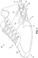
- FIG. 1 illustrates a schematic isometric view of an embodiment of an article of footwear 100, also referred to simply as article 100.
- Article 100 may be configured for use with various kinds of footwear including, but not limited to: hiking boots, soccer shoes, football shoes, sneakers, running shoes, cross-training shoes, rugby shoes, basketball shoes, baseball shoes as well as other kinds of shoes.
- article 100 may be configured for use with various kinds of non-sports related footwear, including, but not limited to: slippers, sandals, high heeled footwear, loafers as well as any other kinds of footwear, apparel and/or sporting equipment (e.g., gloves, helmets, etc.).
- article 100 may be divided into forefoot portion 10, midfoot portion 12 and heel portion 14.
- Forefoot portion 10 may be generally associated with the toes and joints connecting the metatarsals with the phalanges.
- Midfoot portion 12 may be generally associated with the arch of a foot.
- heel portion 14 may be generally associated with the heel of a foot, including the calcaneus bone.
- article 100 may include lateral side 16 and medial side 18.
- lateral side 16 and medial side 18 may be opposing sides of article 100.
- both lateral side 16 and medial side 18 may extend through forefoot portion 10, midfoot portion 12 and heel portion 14.
- forefoot portion 10, midfoot portion 12 and heel portion 14 are only intended for purposes of description and are not intended to demarcate precise regions of article 100.
- lateral side 16 and medial side 18 are intended to represent generally two sides of a component, rather than precisely demarcating article 100 into two halves.
- longitudinal refers to a direction extending a length of a component. In some cases, the longitudinal direction may extend from a forefoot portion to a heel portion of the article.
- lateral refers to a direction extending a width of a component, such as an article. For example, the lateral direction may extend between a medial side and a lateral side of a last member.
- vertical refers to a direction that is perpendicular to both the longitudinal and lateral directions.
- the upwards vertical direction may be oriented away from the ground surface, while the downwards vertical direction may be oriented towards the ground surface. It will be understood that each of these directional adjectives may be also be applied to individual components of article 100 as well.
- Article 100 can include upper 102 and sole structure 110.
- upper 102 may be any type of upper.
- upper 102 may have any design, shape, size and/or color.
- upper 102 could be a high top upper that is shaped to provide high support on an ankle.
- upper 102 could be a low top upper.
- sole structure 110 may be configured to provide traction for article 100. In addition to providing traction, sole structure 110 may attenuate ground reaction forces when compressed between the foot and the ground during walking, running or other ambulatory activities.
- the configuration of sole structure 110 may vary significantly in different embodiments to include a variety of conventional or non-conventional structures. In some cases, the configuration of sole structure 110 can be configured according to one or more types of ground surfaces on which sole structure 110 may be used. Examples of ground surfaces include, but are not limited to: natural turf, synthetic turf, dirt, as well as other surfaces.
- Sole structure 110 is secured to upper 102 and extends between the foot and the ground when article 100 is worn.
- sole structure 110 may include different components.
- sole structure 110 may include an outsole, a midsole, and/or an insole. In some cases, one or more of these components may be optional.
- an article of footwear may be configured with an adaptive support system, which may include provisions for adaptively changing support for an article.
- an adaptive support system can include one or more support members with variable support characteristics.
- FIG. 2 illustrates a schematic plan view of an embodiment of article 100 that is configured with an adaptive support system 115.
- adaptive support system 115 may include one or more support members, which may facilitate shock absorption, energy return and/or cushioning, for example.
- sole structure 110 may include plurality of support members 120 that further comprises first support member 121, second support member 122, third support member 123 and fourth support member 124.
- plurality of support members 120 comprise individual members that are spaced apart from one another.
- first support member 121, second support member 122, third support member 123 and fourth support member 124 are arranged as column-like members that extend between upper plate 130 and lower plate 132.
- plurality of support members 120 may provide support to the heel of a foot, which is generally disposed over upper plate 130 of article 100.
- FIG. 2 Also shown in FIG. 2 are various additional components of adaptive support system 115, which are described in further detail below. It will be understood however, these components and their respective locations within article 100 are optional.
- one or more support members can be configured to provide adaptive support or response to forces applied to article 100 by a user's foot, a ground surface as well as possibly other sources.
- one or more support members can be configured with adaptive shock-absorption, energy return and/or cushioning properties.
- one or more support members can include a portion with variable shock-absorption, cushioning, rigidity and/or other properties.
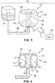
- FIGS. 3 and 4 illustrate an isolated view of an adaptive support assembly 199 that includes first support member 121 (also referred to simply as support member 121) as well as additional components that facilitate the operation of support member 121 in order to provide varying shock-absorption, cushioning and/or other properties for support member 121.
- FIG. 3 illustrates a schematic isometric view of adaptive support assembly 199
- FIG. 4 illustrates a schematic cross-sectional view of some components of adaptive support assembly 199.
- many of the components of adaptive support assembly 199 are shown schematically, and it should be understood that these components could have any other shapes, sizes as well as possibly additional features in other embodiments.
- a support member can be configured with an outer portion that is substantially compressible as well as an inner portion that is at least partially bounded by the outer portion.
- the outer portion may have a substantially fixed compressibility or rigidity
- the compressibility or rigidity of the inner portion could be variable.
- the variable compressibility of the inner portion can be achieved using a fluid having variable viscosity or structural characteristics.
- the inner portion may be a cavity filled with a rheological fluid, including, for example, an electrorheological fluid or a magnetorheological fluid.
- support member 121 is configured as a bladder 160 having an outer chamber 174 and an inner chamber 176.
- the outer chamber 174 is sealed from the inner chamber 176 so that no fluid can be exchanged between the outer chamber 174 and in the inner chamber 176.
- support member 121 may be configured with an outer ring-like (or donut-like) member 161 surrounding a central region.
- the region encircled by member 161 may further be bounded above and below by an upper bladder wall 180 and a lower bladder wall 182. This arrangement creates a sealed inner chamber 176.
- the upper bladder wall 180 and the lower bladder wall 182 may generally be attached to member 161 in a manner that prevents fluid from escaping between member 161 and upper bladder wall 180 and/or lower bladder wall 182.
- upper bladder wall 180 and/or lower bladder wall 182 may be bonded to member 161 using adhesives, thermal bonding, as well as any other methods known in the art for joining layers of a bladder together.
- upper bladder wall 180 and/or lower bladder wall 182 could be integrally formed with member 161.
- a first fluid 189 in the form of a gas or liquid is sealed within the outer chamber 174, between an exterior bladder wall 170 and an interior bladder wall 172. Additionally, a second rheological fluid 190 fills inner chamber 176.
- the first fluid 189 may be air. Therefore, first fluid 189 may be a substantially compressible gas.
- the bladder wall 182 includes a hole or aperture in the form of fluid port 198, which allows second fluid 190 to enter/escape from inner chamber 176. Furthermore, a fluid line 196 facilitates fluid communication between fluid port 198 and a reservoir 194. Although a fluid port 198 is shown in lower bladder wall 182 in this embodiment, other embodiments could incorporate another fluid port in any other portion including, for example upper bladder wall 180.
- Reservoir 194 may house some of the total volume of the second fluid 190, which can flow between reservoir 194 and inner chamber 176, by way of fluid line 196. It will be understood that the shape, size and structural properties of reservoir 194 may vary according to factors including, but not limited to: the total volume of second fluid 190, the volume of inner chamber 176, the volume of fluid line 196, the intended location within an article of reservoir 194, manufacturing considerations as well as possibly other factors.
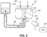
- FIG. 5 A possible mode of operation of adaptive support assembly 199 is shown schematically in FIG. 5 .
- a downward force 200 applied to first support member 121 may act to compress support member 121 in the generally vertical direction.
- outer chamber 174 which is filled with a compressible gas such as air, may temporarily deform or deflect under downward force 200.
- second fluid 190 which is generally an incompressible fluid, is pushed through fluid line 196 and into reservoir 194, thereby allowing inner chamber 174 to deform or deflect along with outer chamber 174.
- the compression of gas within outer chamber 174 stores potential kinetic energy that may cause outer chamber 174 (and with it inner chamber 176) to expand as downward force 200 is diminished and/or completely removed. This arrangement allows first support member 121 to act as a shock-absorber and to provide some energy return.
- first support member 121 is due to the combination of the material properties of the first fluid 189 in outer chamber 174 and the material properties of second fluid 190 in inner chamber 176. Because outer chamber 174 is sealed and the material properties of first fluid 189 are generally unchanged, the compressibility of outer chamber 174 is generally constant and unchanging. However, as second fluid 190 has variable material properties, including viscosity, it is possible to vary the compressibility of inner chamber 176 and therefore the overall compressibility of first support member 121.
- adaptive support assembly 199 includes provisions for controlling the material properties (including viscosity) of second fluid 190.
- Assembly 199 includes an electromagnet device.
- electromagnetic devices include electrical devices, such as capacitors, as well as magnetic devices such as electromagnets.
- an electromagnet device may also comprise a permanent magnet.
- the type of electromagnetic device used may be selected according to the material properties of second fluid 190. For example, where an electrorheological fluid is used, an electromagnetic device may be a capacitor or other electrical device capable of generating an electrical field. In cases where a magnetorheological fluid is used, the electromagnetic device may be an electromagnet.
- adaptive support assembly 199 may include electromagnet 186.
- electromagnet 186 any kind of electromagnet or electromagnetic device known in the art could be used.
- the type of electromagnet used could be selected according to factors including, but not limited to: required field strength, required location within the article, durability, power requirements as well as possibly other factors.
- electromagnet 186 may generally be positioned so that the required range of magnetic forces can be applied to second fluid 190.
- electromagnet 186 can be positioned so that the magnetic field primarily interacts with the volume of second fluid 190 disposed in inner chamber 176.
- electromagnet 186 may be positioned so that the magnetic field primarily interacts with the volume of second fluid 190 disposed in fluid line 196, especially in the vicinity of fluid port 198.
- electromagnet 186 may be positioned so that the magnetic field primarily interacts with the volume of second fluid 190 disposed in reservoir 194.
- electromagnet 186 may be positioned so that the magnetic field interacts with portions of the volume of second fluid 190 disposed within each of reservoir 194, fluid line 196 and inner chamber 176.
- Electromagnet 186 may apply a magnetic field to regions of second fluid 190 that alter the material properties, including the apparent viscosity, of second fluid 190. Varying the viscosity of regions of second fluid 190 may change the rate of fluid flow between inner chamber 176 and reservoir 194. In cases where the viscosity is greatly increased at some regions of second fluid 190, the flow may be substantially stopped. As the viscosity varies in response to the magnetic field, thereby restricting or completely preventing fluid flow, the compressibility of inner chamber 176 (and thus of first support member 121) may vary accordingly.
- inner chamber 176 may remain filled with second fluid 190 and therefore unable to deform, deflect or otherwise vary in shape and/or volume.
- the rate of flow of second fluid 190 can change so that the rate of deformation or deflection, and therefore the compressibility, of inner chamber 176 can be varied accordingly.
- the general incompressibility of second fluid 190 means that the compressibility of inner chamber 176 may be influenced by changes in the fluid viscosity that occur both inside and outside of inner chamber 176.
- electromagnet 186 may be positioned in the vicinity of fluid port 198, so that a magnetic field generated by electromagnet 186 can change the viscosity of second fluid 190 at fluid port 198 as well as possibly within inner chamber 176. This may result in fluid port 198 being substantially closed (i.e., clogged) so that no fluid can flow from inner chamber 176.
- ECU 150 may further include an electronic control unit 150, hereafter referred to simply as ECU 150.
- ECU 150 is described in further detail below.
- a permanent magnet could be configured with a position that varies relative to regions of second fluid 190. As the permanent magnet moves closer to second fluid 190, the increased magnetic field strength increases the viscosity of second fluid 190. This could be accomplished, for example, by placing a compressible material between the magnet and the associated region of second fluid 190, so that as the compressible material is squeezed (e.g., during a ground-contact), the relative distance between the magnet and second fluid 190 decreases.
- a permanent magnet could be associated with an actuating member that automatically adjusts the relative position of the magnet with respect to a corresponding region of second fluid 190.
- FIGS. 6 and 7 illustrate schematic views of two additional operating modes for adaptive support assembly 199.
- electromagnet 186 is operated with a substantially maximum magnetic field strength 210.
- the viscosity of second fluid 190 within inner chamber 176 and in the portion of fluid line 196 adjacent to inner chamber 176 may be greatly increased to the point where substantially no fluid flow is possible even with the application of downward forces 200.
- second fluid 190 remains trapped in inner chamber 176 and thereby prevents first support member 121 from compressing.
- electromagnet 186 is operated with an intermediate magnetic field strength 212 that is less than the maximum magnetic field strength 210.
- second fluid 190 within inner chamber 176 and in the portion of fluid line 196 adjacent to inner chamber 176 may be increased to a point where fluid flow is diminished but not completely stopped.
- second fluid 190 can flow at a substantially reduced rate from inner chamber 176, which allows for some compression of first support member 121.
- electromagnet 186 partially energized ( FIG. 7 )
- the amount of compression experienced by support member 121 is substantially less than the amount of compression experienced by support member 121 with electromagnet 186 off ( FIG. 5 ).
- reservoir 194 may be partially filled with a compressible gas, which may compress as second fluid 190 fills reservoir 194. As downward forces 200 are diminished, the compressed gas in reservoir 194 may expand to push second fluid 190 back into inner chamber 176.
- reservoir 194 may further include one or more actuating systems to push second fluid 190 out of reservoir 194 and into inner chamber 176 (e.g., a piston that reduces the volume of reservoir 194).
- an adaptive support assembly could include additional provisions for controlling the flow of second fluid 190.
- other embodiments could include additional valves or other fluid controlling provisions to facilitate fluid flow in the desired direction and at the desired rate in response to various compressive forces.
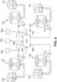
- FIG. 8 illustrates a schematic view of an embodiment of adaptive support system 115 that may include plurality of support members 120 as well as provisions for controlling the material properties of each support member.
- plurality of support members 120 may include first support member 121, second support member 122, third support member 123 and fourth support member 124.
- Each support member can be configured with similar provisions to first support member 121 for adaptively controlling compression, shock-absorption, etc.
- each of second support member 122, third support member 123 and fourth support member 124 may be associated with second reservoir 302, third reservoir 304 and fourth reservoir 306, respectively, as well as associated fluid lines.
- each of second support member 122, third support member 123 and fourth support member 124 may be associated with second electromagnet 310, third electromagnet 312 and fourth electromagnet 314, respectively.
- each electromagnet may be controlled using one or more electronic control units.
- each electromagnet can be associated with ECU 150.
- ECU 150 may include a microprocessor, RAM, ROM, and software all serving to monitor and control various components of adaptive support system 199, as well as other components or systems of article 100.
- ECU 150 is capable of receiving signals from numerous sensors, devices, and systems associated with adaptive support system 199. The output of various devices is sent to ECU 150 where the device signals may be stored in an electronic storage, such as RAM. Both current and electronically stored signals may be processed by a central processing unit (CPU) in accordance with software stored in an electronic memory, such as ROM.
- CPU central processing unit
- ECU 150 may include a number of ports that facilitate the input and output of information and power.
- the term "port" as used throughout this detailed description and in the claims refers to any interface or shared boundary between two conductors. In some cases, ports can facilitate the insertion and removal of conductors. Examples of these types of ports include mechanical connectors. In other cases, ports are interfaces that generally do not provide easy insertion or removal. Examples of these types of ports include soldering or electron traces on circuit boards.
- ECU 150 may include port 351, port 352, port 353 and port 354 for communicating with first electromagnet 186, second electromagnet 310, third electromagnet 312 and fourth electromagnet 314, respectively. Furthermore, in some embodiments ECU 150 may further include port 355, port 356 and port 357 for communicating with sensor 320, sensor 322 and sensor 324, respectively.
- Sensor 320, sensor 322 and sensor 324 could be any sensors configured for use with footwear and/or apparel. In some embodiments, sensor 320, sensor 322 and sensor 324 may be a pressure sensor, a force or strain sensor and an accelerometer. In other embodiments, however, still other sensors could be used. Some embodiments, for example, could also include provisions for receiving GPS information via a GPS antenna.
- each support member can be independently actuated through instructions from ECU 150.
- this arrangement allows the material properties of each support member (i.e., the viscosity of an enclosed magnetorheological fluid) to be independently varied in response to various sensed information including acceleration information, angle or rotation information, speed information, vertical height information, pressure information as well as other kinds of information.
- This allows an article of footwear to adaptively respond to a variety of different situations with the proper type and amount of shock-absorption, cushioning, energy return and comfort.
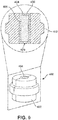
- FIG. 9 illustrates another possible embodiment of a support member 400 that does not belong to the invention configured to have variable material properties.
- support member 400 includes an outer portion 402 comprising a substantially compressible material as well as an inner portion 404.
- inner portion 404 may be comprise an outer barrier layer 405 that encloses a fluid 406.
- fluid 406 is a variable viscosity fluid, such as an electrorheological or magnetorheological fluid. As with the previous embodiments, the viscosity of fluid 406 may vary in response to an applied magnetic field.
- layer 405 may include a fluid port 409 that provides fluid communication between inner portion 404 and an external reservoir of some kind. This arrangement allows fluid 406 to flow into and out of inner portion 404 in a similar manner to the flow of second fluid 190 into and out of inner chamber 176 (see FIG. 5 ).
- outer portion 402 comprises a substantially solid material, rather than a gas filled bladder.
- solid compressible materials that could be used include, but are not limited to: foams, compressible plastics as well as possibly other materials.
- the type of material used for outer portion 402 may be selected according to factors including, but not limited to: manufacturing constraints, desired compressibility, durability, weight, as well as possibly other factors.
- outer portion 402 may comprise a bladder, such as member 161 of the previous embodiments.
- first support member 121, second support member 122, third support member 123 and fourth support member 124 are each configured with respective outer portions and inner portions.
- first support member 121 includes an outer portion including outer chamber 174 and an inner portion including inner chamber 176.
- second support member 122 includes an outer portion including an outer chamber 220 and an inner portion including an inner chamber 222.
- Each of these inner portions have inner chambers filled with a magnetorheological fluid.
- each support member is in fluid communication with a fluid reservoir, including first reservoir 194, second reservoir 302, third reservoir 304 and fourth reservoir 306.
- Each reservoir can be disposed in any region of article 100. In some cases, each reservoir could be mounted to portions of sole structure 110. In other cases, each reservoir could be mounted to portions of upper 102 (not shown). In still other cases, each reservoir could be positioned and mounted in any other portions or locations of article 100.
- each of the support members includes an electromagnet positioned adjacent to the corresponding support member, including first electromagnet 186, second electromagnet 310, third electromagnet 312 and fourth electromagnet 314.
- the electromagnets could be disposed in any portion of article 100 including sole structure 110 and/or upper 102.
- first support member 121, second support member 122, third support member 123 and fourth support member 124 are generally spaced apart so as to facilitate support over different portions of sole structure 110. This spacing facilitates differentiated shock absorption, and may allow for various configurations in which some support members are operated in different operating states or modes than other support members. Such a configuration may occur, for example, during banking.
- FIG. 10 illustrates another embodiment of an article 500 that is banked on a ground surface 502.
- Article 500 includes an upper 512 and a sole structure 510.
- the vertical direction is indicated by axis 520
- the direction normal to ground surface 502 is indicated by axis 522.
- both upper 512 and sole structure 510 are oriented along axis 522.
- both upper 512 and sole structure 510 are oriented, or tilted, at an angle from the true vertical direction.
- FIG. 11 illustrates an embodiment of article 100 banked on a similarly inclined ground surface 602, which shows how article 100 may adaptively respond to changes in surface characteristics (such as surface orientation, angle or shape).
- the vertical direction is indicated by axis 620.
- lower plate 132 of sole structure 110 is sloped along with ground surface 602.
- electromagnet 312 has been activated in order to change the viscosity of the magnetorheological fluid within third support member 123, thereby preventing full compression of third support member 123.
- this activation of electromagnet 312 may occur in response to sensed information, such as information sensed from an accelerometer and/or gyroscope.
- adaptive support system 199 allows upper 102 to remain generally upright without any leaning or tilting that might otherwise occur during banking. This may help improve stability and balance for a user when moving along banked or uneven surfaces.
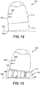
- FIGS. 12 and 13 illustrate views of footwear undergoing banking on a flat surface, which may occur as a user cuts or makes similar lateral movements (for example, on a track or basketball court).
- FIG. 12 shows article of footwear 700 as a user makes a lateral cut on a substantially flat ground surface 702.
- Article 700 includes an upper 712 and a sole structure 710. As the user cuts, the foot tends to push against the outer lateral sidewall 704 (indicated schematically as forces 720). This may tend to cause article 700 to roll or tilt about lower lateral periphery 706.
- FIG. 13 illustrates an embodiment of article of footwear 100 in which a user is making a lateral cut. Moreover, FIG. 13 illustrates how article of footwear 100 may adaptively respond to various kinds of motions such as cutting or lateral motions to help improve stability during these motions.
- the foot tends to push against the outer lateral sidewall 804 (indicated schematically as forces 820).
- adaptive support system 115 responds to this shift in weight by allowing third support member 123 to compress substantially more than second support member 122. This results in a wedge-like configuration for sole structure 110 that resists the tendency of article 100 to roll in the lateral direction about the lower lateral periphery 806 and thereby helps to improve stability.
- adaptive support system 115 may continue to adjust the compression characteristics of each support member accordingly.
Landscapes
- Engineering & Computer Science (AREA)
- Chemical & Material Sciences (AREA)
- Materials Engineering (AREA)
- Microelectronics & Electronic Packaging (AREA)
- Footwear And Its Accessory, Manufacturing Method And Apparatuses (AREA)
Priority Applications (1)
| Application Number | Priority Date | Filing Date | Title |
|---|---|---|---|
| EP21202283.4A EP3984404B1 (en) | 2013-03-05 | 2014-03-04 | Support members with variable viscosity fluid for footwear |
Applications Claiming Priority (3)
| Application Number | Priority Date | Filing Date | Title |
|---|---|---|---|
| US13/784,952 US9198478B2 (en) | 2013-03-05 | 2013-03-05 | Support members with variable viscosity fluid for footwear |
| PCT/US2014/020212 WO2014138020A1 (en) | 2013-03-05 | 2014-03-04 | Support members with variable viscosity fluid for footwear |
| EP14721565.1A EP2964047B1 (en) | 2013-03-05 | 2014-03-04 | Support members with variable viscosity fluid for footwear |
Related Parent Applications (1)
| Application Number | Title | Priority Date | Filing Date |
|---|---|---|---|
| EP14721565.1A Division EP2964047B1 (en) | 2013-03-05 | 2014-03-04 | Support members with variable viscosity fluid for footwear |
Related Child Applications (1)
| Application Number | Title | Priority Date | Filing Date |
|---|---|---|---|
| EP21202283.4A Division EP3984404B1 (en) | 2013-03-05 | 2014-03-04 | Support members with variable viscosity fluid for footwear |
Publications (2)
| Publication Number | Publication Date |
|---|---|
| EP3473125A1 EP3473125A1 (en) | 2019-04-24 |
| EP3473125B1 true EP3473125B1 (en) | 2021-10-13 |
Family
ID=50639896
Family Applications (3)
| Application Number | Title | Priority Date | Filing Date |
|---|---|---|---|
| EP18211211.0A Active EP3473125B1 (en) | 2013-03-05 | 2014-03-04 | Support members with variable viscosity fluid for footwear |
| EP21202283.4A Active EP3984404B1 (en) | 2013-03-05 | 2014-03-04 | Support members with variable viscosity fluid for footwear |
| EP14721565.1A Active EP2964047B1 (en) | 2013-03-05 | 2014-03-04 | Support members with variable viscosity fluid for footwear |
Family Applications After (2)
| Application Number | Title | Priority Date | Filing Date |
|---|---|---|---|
| EP21202283.4A Active EP3984404B1 (en) | 2013-03-05 | 2014-03-04 | Support members with variable viscosity fluid for footwear |
| EP14721565.1A Active EP2964047B1 (en) | 2013-03-05 | 2014-03-04 | Support members with variable viscosity fluid for footwear |
Country Status (5)
| Country | Link |
|---|---|
| US (6) | US9198478B2 (enExample) |
| EP (3) | EP3473125B1 (enExample) |
| JP (3) | JP6322657B2 (enExample) |
| CN (1) | CN105163619B (enExample) |
| WO (1) | WO2014138020A1 (enExample) |
Cited By (1)
| Publication number | Priority date | Publication date | Assignee | Title |
|---|---|---|---|---|
| US12484660B2 (en) | 2013-03-05 | 2025-12-02 | Nike, Inc. | Support members with variable viscosity fluid for footwear |
Families Citing this family (32)
| Publication number | Priority date | Publication date | Assignee | Title |
|---|---|---|---|---|
| US8256147B2 (en) * | 2004-11-22 | 2012-09-04 | Frampton E. Eliis | Devices with internal flexibility sipes, including siped chambers for footwear |
| US12290134B2 (en) * | 2004-11-22 | 2025-05-06 | Frampton E. Ellis | Footwear or orthotic sole with microprocessor control of a structural or support element with magnetorheological fluid |
| US10852069B2 (en) | 2010-05-04 | 2020-12-01 | Fractal Heatsink Technologies, LLC | System and method for maintaining efficiency of a fractal heat sink |
| US11399594B2 (en) * | 2013-05-07 | 2022-08-02 | Danielle M Kassatly | Footwear auxiliaries for synchronously toning leg muscles in order to straighten back posture |
| US10264850B2 (en) * | 2015-02-16 | 2019-04-23 | Vocational Training Council | Flexible cushioning device for shoes and methods of producing the same |
| US9743712B2 (en) | 2015-05-28 | 2017-08-29 | Nike, Inc. | Sole structure with electrically controllable damping element |
| US10070689B2 (en) | 2015-05-28 | 2018-09-11 | Nike, Inc. | Sole structure with electrically controllable damping element |
| US9820531B2 (en) * | 2015-05-29 | 2017-11-21 | Nike, Inc. | Footwear including an incline adjuster |
| CN105962531B (zh) * | 2015-06-12 | 2018-06-05 | 贵人鸟股份有限公司 | 缓震助力的泡泡按摩运动鞋 |
| US10070691B2 (en) | 2015-11-03 | 2018-09-11 | Nike, Inc. | Article of footwear including a bladder element having a cushioning component with a single central opening and a cushioning component with multiple connecting features and method of manufacturing |
| WO2017079255A1 (en) | 2015-11-03 | 2017-05-11 | Nike Innovate C.V. | Sole structure for an article of footwear having a bladder element with laterally-extending tubes and method of manufacturing a sole structure |
| US9775407B2 (en) | 2015-11-03 | 2017-10-03 | Nike, Inc. | Article of footwear including a bladder element having a cushioning component with a single central opening and method of manufacturing |
| KR102585863B1 (ko) * | 2015-11-11 | 2023-10-11 | 삼성전자주식회사 | 착용 가능한 전자장치 디스플레이장치 및 그 제어방법 |
| US10932523B2 (en) * | 2015-11-30 | 2021-03-02 | Nike, Inc. | Electrorheological fluid structure with attached conductor and method of fabrication |
| US10813407B2 (en) * | 2015-11-30 | 2020-10-27 | Nike, Inc. | Electrorheological fluid structure having strain relief element and method of fabrication |
| CN105686205B (zh) * | 2016-03-03 | 2017-11-24 | 重庆邮电大学 | 一种摩擦力可控的足部防滑装置 |
| DE202017100006U1 (de) * | 2017-01-02 | 2018-04-04 | automation & software Günther Tausch GmbH | Schuhsohle zum Messen einer Fußtemperatur und Schuhsohlenpaar, sowie Schuh und Schuhpaar |
| EP3595475B1 (en) | 2017-04-17 | 2021-04-07 | Hewlett-Packard Development Company, L.P. | Vibrators in cells for footwear |
| WO2019046520A1 (en) | 2017-08-31 | 2019-03-07 | Nike Innovate C.V. | MULTI-CHAMBER DISCRETE TILT ADJUSTMENT DEVICE |
| EP4410140A3 (en) | 2017-08-31 | 2024-10-16 | Nike Innovate C.V. | Footwear including an incline adjuster |
| WO2019074588A1 (en) | 2017-10-13 | 2019-04-18 | Nike Innovate C.V. | FOOTWEAR SHOE WITH ELECTRO-HEAT FLUID COMPARTMENT |
| KR102188633B1 (ko) | 2017-10-25 | 2020-12-08 | 나이키 이노베이트 씨.브이. | 사전설정된 사용자 프로파일을 갖는 오토레이싱 신발류 시스템 |
| USD816309S1 (en) * | 2017-12-14 | 2018-05-01 | Nike, Inc. | Shoe |
| CN114532663A (zh) | 2018-05-31 | 2022-05-27 | 耐克创新有限合伙公司 | 在可调节足部支撑系统中可用的流体流动控制装置 |
| WO2021034784A1 (en) | 2019-08-16 | 2021-02-25 | Poltorak Technologies, LLC | Device and method for medical diagnostics |
| USD912949S1 (en) * | 2019-08-30 | 2021-03-16 | Nike, Inc. | Shoe |
| USD915037S1 (en) * | 2019-08-30 | 2021-04-06 | Nike, Inc. | Shoe |
| USD918547S1 (en) | 2019-08-30 | 2021-05-11 | Nike, Inc. | Shoe |
| USD932158S1 (en) * | 2020-10-29 | 2021-10-05 | Nike, Inc. | Shoe |
| KR102462217B1 (ko) * | 2020-12-15 | 2022-11-03 | 한국과학기술연구원 | 스마트 인솔 |
| JP7690347B2 (ja) * | 2021-08-04 | 2025-06-10 | 株式会社栗本鐵工所 | 足裏触覚提示装置 |
| CN113951600B (zh) * | 2021-10-29 | 2023-03-24 | 重庆骓牧智能科技有限公司 | 一种发电鞋子 |
Family Cites Families (58)
| Publication number | Priority date | Publication date | Assignee | Title |
|---|---|---|---|---|
| US3511583A (en) | 1968-09-24 | 1970-05-12 | Gen Motors Corp | Magnetic fluid actuating pump |
| US4053952A (en) | 1975-10-10 | 1977-10-18 | The United States Of America As Represented By The Secretary Of The Department Of Health, Education And Welfare | Magnetic fluid actuated control valve, relief valve and pump |
| US4471538A (en) * | 1982-06-15 | 1984-09-18 | Pomeranz Mark L | Shock absorbing devices using rheopexic fluid |
| JPS6322657U (enExample) | 1986-07-24 | 1988-02-15 | ||
| JPS6398030U (enExample) | 1986-12-15 | 1988-06-24 | ||
| US4928125A (en) | 1987-09-24 | 1990-05-22 | Minolta Camera Kabushiki Kaisha | Liquid drop ejection apparatus using a magnetic fluid |
| JPH01169185A (ja) | 1987-12-23 | 1989-07-04 | Nippon Denso Co Ltd | 流量制御装置 |
| JPH0439484Y2 (enExample) | 1988-04-01 | 1992-09-16 | ||
| JPH0226380A (ja) | 1988-07-13 | 1990-01-29 | Tokyo Tatsuno Co Ltd | ピンチバルブ |
| JP3039997B2 (ja) | 1991-02-15 | 2000-05-08 | 株式会社ブリヂストン | 電気粘性流体応用装置、電気粘性流体応用振動制御装置および電気粘性流体応用固定装置 |
| US5406719A (en) * | 1991-11-01 | 1995-04-18 | Nike, Inc. | Shoe having adjustable cushioning system |
| US5316261A (en) | 1992-10-26 | 1994-05-31 | Northern Research & Engineering Corp. | Fluid conduit having a variable inner diameter |
| IT1282155B1 (it) * | 1995-06-20 | 1998-03-16 | Sadler Sas Di Marc Sadler & C | Calzatura con suola provvista di dispositivo ammortizzatore |
| US5813142A (en) * | 1996-02-09 | 1998-09-29 | Demon; Ronald S. | Shoe sole with an adjustable support pattern |
| JPH10327906A (ja) * | 1997-05-30 | 1998-12-15 | Asahi Corp | 靴底踵部用衝撃吸収材 |
| IT1292147B1 (it) * | 1997-06-12 | 1999-01-25 | Global Sports Tech Inc | Calzatura sportiva incorporante una pluralita' di inserti aventi differenti risposte elastiche alla sollecitazione del piede |
| DE19725685B4 (de) | 1997-06-18 | 2006-11-30 | Fludicon Gmbh | Fluid-Pumpe |
| US7219449B1 (en) * | 1999-05-03 | 2007-05-22 | Promdx Technology, Inc. | Adaptively controlled footwear |
| US6568102B1 (en) * | 2000-02-24 | 2003-05-27 | Converse Inc. | Shoe having shock-absorber element in sole |
| US6875241B2 (en) * | 2000-06-30 | 2005-04-05 | Roland J. Christensen, As Operating Manager Of Rjc Development Lc, General Partner Of The Roland J. Christensen Family Limited Partnership | Variable resistance cell |
| JP2003031535A (ja) * | 2001-07-11 | 2003-01-31 | Mitsubishi Electric Corp | 半導体製造装置の超音波洗浄方法 |
| DE10240530A1 (de) * | 2002-09-03 | 2004-03-11 | Völkl Tennis GmbH | Schuh bzw. Sportschuh |
| US7188439B2 (en) * | 2003-03-10 | 2007-03-13 | Adidas International Marketing B.V. | Intelligent footwear systems |
| US7631382B2 (en) * | 2003-03-10 | 2009-12-15 | Adidas International Marketing B.V. | Intelligent footwear systems |
| US7396574B2 (en) * | 2003-05-28 | 2008-07-08 | Robert C. Bogert | Self-inflating cushion and footwear including same |
| US7051456B2 (en) * | 2003-07-29 | 2006-05-30 | Nike, Inc. | Article of footwear incorporating an inflatable chamber |
| US7254908B2 (en) * | 2004-02-06 | 2007-08-14 | Nike, Inc. | Article of footwear with variable support structure |
| US7383648B1 (en) * | 2004-02-23 | 2008-06-10 | Reebok International Ltd. | Inflatable support system for an article of footwear |
| US8291618B2 (en) * | 2004-11-22 | 2012-10-23 | Frampton E. Ellis | Devices with internal flexibility sipes, including siped chambers for footwear |
| CA2630817C (en) * | 2004-11-22 | 2016-10-18 | Frampton E. Ellis | Devices with internal flexibility sipes, including siped chambers for footwear |
| US20060248750A1 (en) * | 2005-05-06 | 2006-11-09 | Outland Research, Llc | Variable support footwear using electrorheological or magnetorheological fluids |
| US8468722B2 (en) * | 2005-08-03 | 2013-06-25 | Inventus Engineering Gmbh | Shoe, in particular running shoe or ski boot, and skiing equipment |
| US7409779B2 (en) * | 2005-10-19 | 2008-08-12 | Nike, Inc. | Fluid system having multiple pump chambers |
| US7566209B2 (en) | 2006-03-15 | 2009-07-28 | Chrysler Llc | Peristaltic pump with field generator |
| WO2007125148A1 (es) | 2006-04-27 | 2007-11-08 | Universidad De Granada | Calzado con amortiguación |
| US7607243B2 (en) * | 2006-05-03 | 2009-10-27 | Nike, Inc. | Athletic or other performance sensing systems |
| CA2687650C (en) * | 2006-05-19 | 2016-02-16 | Frampton E. Ellis | Devices with internal flexibility sipes, including siped chambers for footwear |
| US8261469B2 (en) * | 2006-07-21 | 2012-09-11 | Nike, Inc. | Articles of footwear and other foot-receiving devices including differently oriented impact-attenuation elements |
| US7685742B2 (en) * | 2006-07-21 | 2010-03-30 | Nike, Inc. | Impact-attenuation systems for articles of footwear and other foot-receiving devices |
| US7877898B2 (en) * | 2006-07-21 | 2011-02-01 | Nike, Inc. | Impact-attenuation systems for articles of footwear and other foot-receiving devices |
| US7841108B2 (en) * | 2007-05-29 | 2010-11-30 | Nike, Inc. | Article of footwear with visible indicia |
| DE102007045110B4 (de) * | 2007-09-20 | 2010-05-20 | Inventus Engineering Gmbh | Ventil für magnetorheologische Flüssigkeiten |
| US8978273B2 (en) * | 2007-10-19 | 2015-03-17 | Nike, Inc. | Article of footwear with a sole structure having fluid-filled support elements |
| US8561963B2 (en) | 2007-12-19 | 2013-10-22 | Palo Alto Research Center Incorporated | Electrostatically addressable microvalves |
| US7937856B2 (en) * | 2007-12-21 | 2011-05-10 | Nike, Inc. | Article of footwear with illuminated chamber |
| DE102008027104A1 (de) * | 2008-06-06 | 2009-12-10 | Cairos Technologies Ag | System und Verfahren zur mobilen Bewertung von Schuhdämpfungseigenschaften |
| US10070680B2 (en) | 2008-06-13 | 2018-09-11 | Nike, Inc. | Footwear having sensor system |
| US9055782B2 (en) * | 2008-10-24 | 2015-06-16 | Kevin McDonnell | Multistructural support system for a sole in a running shoe |
| US8943709B2 (en) * | 2008-11-06 | 2015-02-03 | Nike, Inc. | Article of footwear with support columns having fluid-filled bladders |
| US8800167B2 (en) * | 2009-09-19 | 2014-08-12 | Harold S. Doyle | Pneumatic inflating device contained entirely within shoe sole |
| KR20130007809A (ko) * | 2011-07-11 | 2013-01-21 | 박선환 | 유압을 이용한 신발완충장치 |
| US10016017B2 (en) * | 2011-12-29 | 2018-07-10 | Reebok International Limited | Sole and article of footwear having a pod assembly |
| US9030335B2 (en) * | 2012-04-18 | 2015-05-12 | Frampton E. Ellis | Smartphones app-controlled configuration of footwear soles using sensors in the smartphone and the soles |
| EP2951627B1 (en) | 2013-02-01 | 2018-10-24 | Polyvalor, Limited Partnership | Asymmetric optical fiber coupler |
| US9198478B2 (en) | 2013-03-05 | 2015-12-01 | Nike, Inc. | Support members with variable viscosity fluid for footwear |
| US9359992B2 (en) * | 2013-03-08 | 2016-06-07 | Ologn Technologies Ag | Systems, methods and apparatuses for harvesting power generated in a footwear |
| US9603414B2 (en) * | 2013-03-15 | 2017-03-28 | Nike, Inc. | Fluid-filled chamber with a tensile element |
| JP6776819B2 (ja) | 2016-10-31 | 2020-10-28 | Tdk株式会社 | 方向性結合器 |
-
2013
- 2013-03-05 US US13/784,952 patent/US9198478B2/en active Active
-
2014
- 2014-03-04 WO PCT/US2014/020212 patent/WO2014138020A1/en not_active Ceased
- 2014-03-04 EP EP18211211.0A patent/EP3473125B1/en active Active
- 2014-03-04 EP EP21202283.4A patent/EP3984404B1/en active Active
- 2014-03-04 CN CN201480024586.3A patent/CN105163619B/zh active Active
- 2014-03-04 JP JP2015561529A patent/JP6322657B2/ja active Active
- 2014-03-04 EP EP14721565.1A patent/EP2964047B1/en active Active
-
2015
- 2015-10-29 US US14/926,785 patent/US10058146B2/en active Active
-
2018
- 2018-04-09 JP JP2018074434A patent/JP6398030B2/ja active Active
- 2018-08-01 US US16/051,656 patent/US10834997B2/en active Active
- 2018-09-03 JP JP2018164201A patent/JP6739484B2/ja active Active
-
2020
- 2020-11-16 US US17/098,595 patent/US11490685B2/en active Active
-
2022
- 2022-11-07 US US17/981,644 patent/US12029275B2/en active Active
-
2024
- 2024-07-08 US US18/765,979 patent/US12484660B2/en active Active
Non-Patent Citations (1)
| Title |
|---|
| None * |
Cited By (1)
| Publication number | Priority date | Publication date | Assignee | Title |
|---|---|---|---|---|
| US12484660B2 (en) | 2013-03-05 | 2025-12-02 | Nike, Inc. | Support members with variable viscosity fluid for footwear |
Also Published As
| Publication number | Publication date |
|---|---|
| CN105163619B (zh) | 2017-04-12 |
| US12029275B2 (en) | 2024-07-09 |
| US20240358114A1 (en) | 2024-10-31 |
| EP3473125A1 (en) | 2019-04-24 |
| US10058146B2 (en) | 2018-08-28 |
| JP2016508837A (ja) | 2016-03-24 |
| EP2964047A1 (en) | 2016-01-13 |
| US20160044993A1 (en) | 2016-02-18 |
| JP2018202197A (ja) | 2018-12-27 |
| US11490685B2 (en) | 2022-11-08 |
| EP3984404A1 (en) | 2022-04-20 |
| EP2964047B1 (en) | 2018-12-12 |
| US9198478B2 (en) | 2015-12-01 |
| US12484660B2 (en) | 2025-12-02 |
| JP6398030B2 (ja) | 2018-09-26 |
| US10834997B2 (en) | 2020-11-17 |
| US20210298418A1 (en) | 2021-09-30 |
| EP3984404B1 (en) | 2024-08-28 |
| US20140250726A1 (en) | 2014-09-11 |
| CN105163619A (zh) | 2015-12-16 |
| JP6739484B2 (ja) | 2020-08-12 |
| US20230065218A1 (en) | 2023-03-02 |
| JP6322657B2 (ja) | 2018-05-09 |
| US20180338576A1 (en) | 2018-11-29 |
| WO2014138020A1 (en) | 2014-09-12 |
| JP2018134450A (ja) | 2018-08-30 |
Similar Documents
| Publication | Publication Date | Title |
|---|---|---|
| US12484660B2 (en) | Support members with variable viscosity fluid for footwear | |
| US12150517B2 (en) | Electronically controlled bladder assembly | |
| CA2885042C (en) | Sole structures and articles of footwear having plate moderated fluid-filled bladders and/or foam type impact force attenuation members | |
| US9480298B2 (en) | Article of footwear with support assembly having primary and secondary members |
Legal Events
| Date | Code | Title | Description |
|---|---|---|---|
| PUAI | Public reference made under article 153(3) epc to a published international application that has entered the european phase |
Free format text: ORIGINAL CODE: 0009012 |
|
| STAA | Information on the status of an ep patent application or granted ep patent |
Free format text: STATUS: THE APPLICATION HAS BEEN PUBLISHED |
|
| AC | Divisional application: reference to earlier application |
Ref document number: 2964047 Country of ref document: EP Kind code of ref document: P |
|
| AK | Designated contracting states |
Kind code of ref document: A1 Designated state(s): AL AT BE BG CH CY CZ DE DK EE ES FI FR GB GR HR HU IE IS IT LI LT LU LV MC MK MT NL NO PL PT RO RS SE SI SK SM TR |
|
| STAA | Information on the status of an ep patent application or granted ep patent |
Free format text: STATUS: REQUEST FOR EXAMINATION WAS MADE |
|
| 17P | Request for examination filed |
Effective date: 20191024 |
|
| RBV | Designated contracting states (corrected) |
Designated state(s): AL AT BE BG CH CY CZ DE DK EE ES FI FR GB GR HR HU IE IS IT LI LT LU LV MC MK MT NL NO PL PT RO RS SE SI SK SM TR |
|
| STAA | Information on the status of an ep patent application or granted ep patent |
Free format text: STATUS: EXAMINATION IS IN PROGRESS |
|
| 17Q | First examination report despatched |
Effective date: 20191220 |
|
| REG | Reference to a national code |
Ref country code: DE Ref legal event code: R079 Ref document number: 602014080714 Country of ref document: DE Free format text: PREVIOUS MAIN CLASS: A43B0013200000 Ipc: A43B0001000000 |
|
| GRAP | Despatch of communication of intention to grant a patent |
Free format text: ORIGINAL CODE: EPIDOSNIGR1 |
|
| STAA | Information on the status of an ep patent application or granted ep patent |
Free format text: STATUS: GRANT OF PATENT IS INTENDED |
|
| RIC1 | Information provided on ipc code assigned before grant |
Ipc: A43B 1/00 20060101AFI20210407BHEP |
|
| INTG | Intention to grant announced |
Effective date: 20210429 |
|
| GRAS | Grant fee paid |
Free format text: ORIGINAL CODE: EPIDOSNIGR3 |
|
| GRAA | (expected) grant |
Free format text: ORIGINAL CODE: 0009210 |
|
| STAA | Information on the status of an ep patent application or granted ep patent |
Free format text: STATUS: THE PATENT HAS BEEN GRANTED |
|
| AC | Divisional application: reference to earlier application |
Ref document number: 2964047 Country of ref document: EP Kind code of ref document: P |
|
| AK | Designated contracting states |
Kind code of ref document: B1 Designated state(s): AL AT BE BG CH CY CZ DE DK EE ES FI FR GB GR HR HU IE IS IT LI LT LU LV MC MK MT NL NO PL PT RO RS SE SI SK SM TR |
|
| REG | Reference to a national code |
Ref country code: GB Ref legal event code: FG4D |
|
| REG | Reference to a national code |
Ref country code: CH Ref legal event code: EP |
|
| REG | Reference to a national code |
Ref country code: DE Ref legal event code: R096 Ref document number: 602014080714 Country of ref document: DE |
|
| REG | Reference to a national code |
Ref country code: IE Ref legal event code: FG4D |
|
| REG | Reference to a national code |
Ref country code: AT Ref legal event code: REF Ref document number: 1437474 Country of ref document: AT Kind code of ref document: T Effective date: 20211115 |
|
| REG | Reference to a national code |
Ref country code: LT Ref legal event code: MG9D |
|
| REG | Reference to a national code |
Ref country code: NL Ref legal event code: MP Effective date: 20211013 |
|
| REG | Reference to a national code |
Ref country code: AT Ref legal event code: MK05 Ref document number: 1437474 Country of ref document: AT Kind code of ref document: T Effective date: 20211013 |
|
| PG25 | Lapsed in a contracting state [announced via postgrant information from national office to epo] |
Ref country code: RS Free format text: LAPSE BECAUSE OF FAILURE TO SUBMIT A TRANSLATION OF THE DESCRIPTION OR TO PAY THE FEE WITHIN THE PRESCRIBED TIME-LIMIT Effective date: 20211013 Ref country code: LT Free format text: LAPSE BECAUSE OF FAILURE TO SUBMIT A TRANSLATION OF THE DESCRIPTION OR TO PAY THE FEE WITHIN THE PRESCRIBED TIME-LIMIT Effective date: 20211013 Ref country code: FI Free format text: LAPSE BECAUSE OF FAILURE TO SUBMIT A TRANSLATION OF THE DESCRIPTION OR TO PAY THE FEE WITHIN THE PRESCRIBED TIME-LIMIT Effective date: 20211013 Ref country code: BG Free format text: LAPSE BECAUSE OF FAILURE TO SUBMIT A TRANSLATION OF THE DESCRIPTION OR TO PAY THE FEE WITHIN THE PRESCRIBED TIME-LIMIT Effective date: 20220113 Ref country code: AT Free format text: LAPSE BECAUSE OF FAILURE TO SUBMIT A TRANSLATION OF THE DESCRIPTION OR TO PAY THE FEE WITHIN THE PRESCRIBED TIME-LIMIT Effective date: 20211013 |
|
| PG25 | Lapsed in a contracting state [announced via postgrant information from national office to epo] |
Ref country code: IS Free format text: LAPSE BECAUSE OF FAILURE TO SUBMIT A TRANSLATION OF THE DESCRIPTION OR TO PAY THE FEE WITHIN THE PRESCRIBED TIME-LIMIT Effective date: 20220213 Ref country code: SE Free format text: LAPSE BECAUSE OF FAILURE TO SUBMIT A TRANSLATION OF THE DESCRIPTION OR TO PAY THE FEE WITHIN THE PRESCRIBED TIME-LIMIT Effective date: 20211013 Ref country code: PT Free format text: LAPSE BECAUSE OF FAILURE TO SUBMIT A TRANSLATION OF THE DESCRIPTION OR TO PAY THE FEE WITHIN THE PRESCRIBED TIME-LIMIT Effective date: 20220214 Ref country code: PL Free format text: LAPSE BECAUSE OF FAILURE TO SUBMIT A TRANSLATION OF THE DESCRIPTION OR TO PAY THE FEE WITHIN THE PRESCRIBED TIME-LIMIT Effective date: 20211013 Ref country code: NO Free format text: LAPSE BECAUSE OF FAILURE TO SUBMIT A TRANSLATION OF THE DESCRIPTION OR TO PAY THE FEE WITHIN THE PRESCRIBED TIME-LIMIT Effective date: 20220113 Ref country code: NL Free format text: LAPSE BECAUSE OF FAILURE TO SUBMIT A TRANSLATION OF THE DESCRIPTION OR TO PAY THE FEE WITHIN THE PRESCRIBED TIME-LIMIT Effective date: 20211013 Ref country code: LV Free format text: LAPSE BECAUSE OF FAILURE TO SUBMIT A TRANSLATION OF THE DESCRIPTION OR TO PAY THE FEE WITHIN THE PRESCRIBED TIME-LIMIT Effective date: 20211013 Ref country code: HR Free format text: LAPSE BECAUSE OF FAILURE TO SUBMIT A TRANSLATION OF THE DESCRIPTION OR TO PAY THE FEE WITHIN THE PRESCRIBED TIME-LIMIT Effective date: 20211013 Ref country code: GR Free format text: LAPSE BECAUSE OF FAILURE TO SUBMIT A TRANSLATION OF THE DESCRIPTION OR TO PAY THE FEE WITHIN THE PRESCRIBED TIME-LIMIT Effective date: 20220114 Ref country code: ES Free format text: LAPSE BECAUSE OF FAILURE TO SUBMIT A TRANSLATION OF THE DESCRIPTION OR TO PAY THE FEE WITHIN THE PRESCRIBED TIME-LIMIT Effective date: 20211013 |
|
| REG | Reference to a national code |
Ref country code: DE Ref legal event code: R097 Ref document number: 602014080714 Country of ref document: DE |
|
| PG25 | Lapsed in a contracting state [announced via postgrant information from national office to epo] |
Ref country code: SM Free format text: LAPSE BECAUSE OF FAILURE TO SUBMIT A TRANSLATION OF THE DESCRIPTION OR TO PAY THE FEE WITHIN THE PRESCRIBED TIME-LIMIT Effective date: 20211013 Ref country code: SK Free format text: LAPSE BECAUSE OF FAILURE TO SUBMIT A TRANSLATION OF THE DESCRIPTION OR TO PAY THE FEE WITHIN THE PRESCRIBED TIME-LIMIT Effective date: 20211013 Ref country code: RO Free format text: LAPSE BECAUSE OF FAILURE TO SUBMIT A TRANSLATION OF THE DESCRIPTION OR TO PAY THE FEE WITHIN THE PRESCRIBED TIME-LIMIT Effective date: 20211013 Ref country code: EE Free format text: LAPSE BECAUSE OF FAILURE TO SUBMIT A TRANSLATION OF THE DESCRIPTION OR TO PAY THE FEE WITHIN THE PRESCRIBED TIME-LIMIT Effective date: 20211013 Ref country code: DK Free format text: LAPSE BECAUSE OF FAILURE TO SUBMIT A TRANSLATION OF THE DESCRIPTION OR TO PAY THE FEE WITHIN THE PRESCRIBED TIME-LIMIT Effective date: 20211013 Ref country code: CZ Free format text: LAPSE BECAUSE OF FAILURE TO SUBMIT A TRANSLATION OF THE DESCRIPTION OR TO PAY THE FEE WITHIN THE PRESCRIBED TIME-LIMIT Effective date: 20211013 |
|
| PLBE | No opposition filed within time limit |
Free format text: ORIGINAL CODE: 0009261 |
|
| STAA | Information on the status of an ep patent application or granted ep patent |
Free format text: STATUS: NO OPPOSITION FILED WITHIN TIME LIMIT |
|
| 26N | No opposition filed |
Effective date: 20220714 |
|
| PG25 | Lapsed in a contracting state [announced via postgrant information from national office to epo] |
Ref country code: MC Free format text: LAPSE BECAUSE OF FAILURE TO SUBMIT A TRANSLATION OF THE DESCRIPTION OR TO PAY THE FEE WITHIN THE PRESCRIBED TIME-LIMIT Effective date: 20211013 Ref country code: AL Free format text: LAPSE BECAUSE OF FAILURE TO SUBMIT A TRANSLATION OF THE DESCRIPTION OR TO PAY THE FEE WITHIN THE PRESCRIBED TIME-LIMIT Effective date: 20211013 |
|
| REG | Reference to a national code |
Ref country code: CH Ref legal event code: PL |
|
| PG25 | Lapsed in a contracting state [announced via postgrant information from national office to epo] |
Ref country code: SI Free format text: LAPSE BECAUSE OF FAILURE TO SUBMIT A TRANSLATION OF THE DESCRIPTION OR TO PAY THE FEE WITHIN THE PRESCRIBED TIME-LIMIT Effective date: 20211013 |
|
| REG | Reference to a national code |
Ref country code: BE Ref legal event code: MM Effective date: 20220331 |
|
| PG25 | Lapsed in a contracting state [announced via postgrant information from national office to epo] |
Ref country code: LU Free format text: LAPSE BECAUSE OF NON-PAYMENT OF DUE FEES Effective date: 20220304 Ref country code: LI Free format text: LAPSE BECAUSE OF NON-PAYMENT OF DUE FEES Effective date: 20220331 Ref country code: IE Free format text: LAPSE BECAUSE OF NON-PAYMENT OF DUE FEES Effective date: 20220304 Ref country code: CH Free format text: LAPSE BECAUSE OF NON-PAYMENT OF DUE FEES Effective date: 20220331 |
|
| PG25 | Lapsed in a contracting state [announced via postgrant information from national office to epo] |
Ref country code: BE Free format text: LAPSE BECAUSE OF NON-PAYMENT OF DUE FEES Effective date: 20220331 |
|
| PG25 | Lapsed in a contracting state [announced via postgrant information from national office to epo] |
Ref country code: IT Free format text: LAPSE BECAUSE OF FAILURE TO SUBMIT A TRANSLATION OF THE DESCRIPTION OR TO PAY THE FEE WITHIN THE PRESCRIBED TIME-LIMIT Effective date: 20211013 |
|
| P01 | Opt-out of the competence of the unified patent court (upc) registered |
Effective date: 20230515 |
|
| PG25 | Lapsed in a contracting state [announced via postgrant information from national office to epo] |
Ref country code: HU Free format text: LAPSE BECAUSE OF FAILURE TO SUBMIT A TRANSLATION OF THE DESCRIPTION OR TO PAY THE FEE WITHIN THE PRESCRIBED TIME-LIMIT; INVALID AB INITIO Effective date: 20140304 |
|
| PG25 | Lapsed in a contracting state [announced via postgrant information from national office to epo] |
Ref country code: MK Free format text: LAPSE BECAUSE OF FAILURE TO SUBMIT A TRANSLATION OF THE DESCRIPTION OR TO PAY THE FEE WITHIN THE PRESCRIBED TIME-LIMIT Effective date: 20211013 Ref country code: CY Free format text: LAPSE BECAUSE OF FAILURE TO SUBMIT A TRANSLATION OF THE DESCRIPTION OR TO PAY THE FEE WITHIN THE PRESCRIBED TIME-LIMIT Effective date: 20211013 |
|
| PG25 | Lapsed in a contracting state [announced via postgrant information from national office to epo] |
Ref country code: MT Free format text: LAPSE BECAUSE OF FAILURE TO SUBMIT A TRANSLATION OF THE DESCRIPTION OR TO PAY THE FEE WITHIN THE PRESCRIBED TIME-LIMIT Effective date: 20211013 |
|
| PGFP | Annual fee paid to national office [announced via postgrant information from national office to epo] |
Ref country code: FR Payment date: 20241231 Year of fee payment: 12 |
|
| PGFP | Annual fee paid to national office [announced via postgrant information from national office to epo] |
Ref country code: DE Payment date: 20241231 Year of fee payment: 12 |
|
| PGFP | Annual fee paid to national office [announced via postgrant information from national office to epo] |
Ref country code: GB Payment date: 20250102 Year of fee payment: 12 |
|
| PG25 | Lapsed in a contracting state [announced via postgrant information from national office to epo] |
Ref country code: TR Free format text: LAPSE BECAUSE OF FAILURE TO SUBMIT A TRANSLATION OF THE DESCRIPTION OR TO PAY THE FEE WITHIN THE PRESCRIBED TIME-LIMIT Effective date: 20211013 |