EP3472485B1 - Velocity dependent mechanical brake for clutch actuator - Google Patents
Velocity dependent mechanical brake for clutch actuator Download PDFInfo
- Publication number
- EP3472485B1 EP3472485B1 EP17758263.2A EP17758263A EP3472485B1 EP 3472485 B1 EP3472485 B1 EP 3472485B1 EP 17758263 A EP17758263 A EP 17758263A EP 3472485 B1 EP3472485 B1 EP 3472485B1
- Authority
- EP
- European Patent Office
- Prior art keywords
- clutch actuator
- threaded rod
- clutch
- actuator assembly
- engine
- Prior art date
- Legal status (The legal status is an assumption and is not a legal conclusion. Google has not performed a legal analysis and makes no representation as to the accuracy of the status listed.)
- Active
Links
Images
Classifications
-
- F—MECHANICAL ENGINEERING; LIGHTING; HEATING; WEAPONS; BLASTING
- F16—ENGINEERING ELEMENTS AND UNITS; GENERAL MEASURES FOR PRODUCING AND MAINTAINING EFFECTIVE FUNCTIONING OF MACHINES OR INSTALLATIONS; THERMAL INSULATION IN GENERAL
- F16D—COUPLINGS FOR TRANSMITTING ROTATION; CLUTCHES; BRAKES
- F16D67/00—Combinations of couplings and brakes; Combinations of clutches and brakes
- F16D67/02—Clutch-brake combinations
-
- F—MECHANICAL ENGINEERING; LIGHTING; HEATING; WEAPONS; BLASTING
- F16—ENGINEERING ELEMENTS AND UNITS; GENERAL MEASURES FOR PRODUCING AND MAINTAINING EFFECTIVE FUNCTIONING OF MACHINES OR INSTALLATIONS; THERMAL INSULATION IN GENERAL
- F16D—COUPLINGS FOR TRANSMITTING ROTATION; CLUTCHES; BRAKES
- F16D23/00—Details of mechanically-actuated clutches not specific for one distinct type
-
- F—MECHANICAL ENGINEERING; LIGHTING; HEATING; WEAPONS; BLASTING
- F16—ENGINEERING ELEMENTS AND UNITS; GENERAL MEASURES FOR PRODUCING AND MAINTAINING EFFECTIVE FUNCTIONING OF MACHINES OR INSTALLATIONS; THERMAL INSULATION IN GENERAL
- F16D—COUPLINGS FOR TRANSMITTING ROTATION; CLUTCHES; BRAKES
- F16D28/00—Electrically-actuated clutches
-
- F—MECHANICAL ENGINEERING; LIGHTING; HEATING; WEAPONS; BLASTING
- F16—ENGINEERING ELEMENTS AND UNITS; GENERAL MEASURES FOR PRODUCING AND MAINTAINING EFFECTIVE FUNCTIONING OF MACHINES OR INSTALLATIONS; THERMAL INSULATION IN GENERAL
- F16D—COUPLINGS FOR TRANSMITTING ROTATION; CLUTCHES; BRAKES
- F16D23/00—Details of mechanically-actuated clutches not specific for one distinct type
- F16D23/12—Mechanical clutch-actuating mechanisms arranged outside the clutch as such
- F16D2023/123—Clutch actuation by cams, ramps or ball-screw mechanisms
-
- F—MECHANICAL ENGINEERING; LIGHTING; HEATING; WEAPONS; BLASTING
- F16—ENGINEERING ELEMENTS AND UNITS; GENERAL MEASURES FOR PRODUCING AND MAINTAINING EFFECTIVE FUNCTIONING OF MACHINES OR INSTALLATIONS; THERMAL INSULATION IN GENERAL
- F16D—COUPLINGS FOR TRANSMITTING ROTATION; CLUTCHES; BRAKES
- F16D2121/00—Type of actuator operation force
- F16D2121/14—Mechanical
-
- F—MECHANICAL ENGINEERING; LIGHTING; HEATING; WEAPONS; BLASTING
- F16—ENGINEERING ELEMENTS AND UNITS; GENERAL MEASURES FOR PRODUCING AND MAINTAINING EFFECTIVE FUNCTIONING OF MACHINES OR INSTALLATIONS; THERMAL INSULATION IN GENERAL
- F16D—COUPLINGS FOR TRANSMITTING ROTATION; CLUTCHES; BRAKES
- F16D2125/00—Components of actuators
- F16D2125/18—Mechanical mechanisms
- F16D2125/20—Mechanical mechanisms converting rotation to linear movement or vice versa
- F16D2125/34—Mechanical mechanisms converting rotation to linear movement or vice versa acting in the direction of the axis of rotation
- F16D2125/40—Screw-and-nut
Definitions
- the subject invention relates to clutch systems and, more particularly, to a velocity dependent brake for a clutch actuator.
- Vehicles may employ a clutch to aid in changing between gears. More specifically, the clutch may transition between an engaged state and a disengaged state. In the engaged state, the clutch is operably coupled to a fly wheel transmitting power from an engine to a transmission. In the disengaged state, the clutch is released from the fly wheel decoupling the engine and the transmission.
- Clutch actuators are known, for example, from DE 103 03 141 A1 and US 2013/0146417 A1 .
- a clutch actuator works against a load in a single direction, e.g., going from an engaged to a disengaged state.
- AMT automatic manual transmission
- Using existing engines to control clutch actuator engagement may detract from overall vehicle efficiency. Accordingly, it is desirable to provide a system that may be employed to control clutch engagement without placing additional loads on existing systems.
- a clutch actuator assembly includes a drive member, a threaded rod including a first end operatively connected to the drive member, a second end, and an intermediate portion including a plurality of threads extending therebetween.
- a member is threadably engaged with the plurality of threads of the threaded rod, a clutch actuator member is arranged at the second end of the threaded rod, and a velocity brake is operatively coupled to the threaded rod. The velocity brake decelerates rotation of the threaded rod.
- a transmission system includes a body housing a plurality of gears, and a clutch assembly mounted to the body.
- the clutch assembly provides a selectively engageable interface to an engine.
- a clutch actuator assembly is operatively connected to the clutch assembly.
- the clutch actuator assembly includes a drive member, a threaded rod including a first end operatively connected to the drive member, a second end, and an intermediate portion including a plurality of threads extending therebetween, a member threadably engaged with the plurality of threads of the threaded rod, a clutch actuator member arranged at the second end of the threaded rod, and a velocity brake operatively coupled to the threaded rod.
- the velocity brake decelerates rotation of the threaded rod.
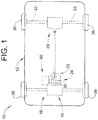
- Vehicle 10 in accordance with an exemplary embodiment is indicated generally at 10 in FIG. 1 .
- Vehicle 10 includes a body 12 supported on a chassis (not shown).
- Vehicle 10 also includes a drivetrain 16 having a prime mover or engine 19 operatively connected to a transmission system 22 through a clutch assembly 24.
- Engine 19 may take on a variety of forms including internal combustion engines, electric engines, and hybrid electric/combustion engines.
- Transmission system 22 may take the form of an automated manual transmission (AMT).
- Clutch assembly 24 includes a clutch 26 which may take the form of a friction disc (not separately labeled) that provides a selective interface between transmission system 22 and engine 19.
- Transmission system 22 is operatively connected to a rear differential 29 which provides power through first and second axles 32 and 33 to corresponding first and second rear wheels 35 and 36.
- Vehicle 10 is also shown to include first and second front wheels 38 and 39. It is to be understood that the number and arrangement of wheels may vary. It is also to be understood that transmission system 22 could alternatively be coupled to first and second front wheels 38 and 39.
- vehicle 10 also includes a clutch actuator assembly 50 that selectively disengages and controllably engages clutch 26.
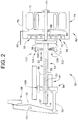
- clutch actuator assembly 50 includes a threaded rod 54 which may take the form of a ball screw 55 having a first end 56, a second end 57, and an intermediate portion 58 supporting a plurality of threads 59 extending therebetween.
- a drive member 60 rotates ball screw 55 about an axis "A". More specifically, first end 56 of ball screw 55 is operatively connected to drive member 60.
- a gear set 65 may provide an interface between ball screw 55 and drive member 60.
- Gear set 65 may take the form of a planetary gear set 66 having a sun gear 68 and a plurality of planet gears 70 that are coupled to first end 56 through a bracket 72.
- Drive member 60 may take the form of an electric engine 74 having a housing 76 that may enclose a stator 78 and a rotor 80 mounted to a shaft 82 connected to sun gear 68.
- Electric engine 74 may be coupled to a control system (not shown) that provides a control signal through a conductor 85.
- Clutch actuator assembly 50 also includes a member 87 threadably supported on threaded rod 54.
- Member 87 may take the form of a ball nut 89 that may transition along intermediate portion 58 between first and second ends 56 and 57 when threaded rod 54 is rotated.
- Clutch actuator assembly 50 further includes a clutch actuator member 94 that is selectively engaged by ball nut 89.
- Clutch actuator member 94 is operatively connected to a clutch lever 96 through a pushrod 99.
- Clutch lever 96 pivots about a point 104 to shift a clutch release bearing 106 into and out of engagement with fingers (not shown) on a pressure plate (also not shown) to release and/or engage clutch 26 with the flywheel.
- Clutch actuator assembly 50 may also include a position sensor 109 that may provide position feedback to the controller in order to enhance clutch engagement and assist in determining clutch wear.
- clutch actuator assembly 50 includes a velocity brake 120 operatively connected to ball screw 55.
- Velocity brake 120 operates to slow rotation of ball screw 55 when clutch 26 shifts from a disengaged configuration to an engaged configuration.
- Velocity brake 120 includes a stationary member 124 and a rotating member 128. Rotating member 128 interacts with stationary member 124 to impede rotation of ball screw 55.
- Stationary member 124 includes a first surface 130 and rotating member 128 includes a second surface 132.
- a compliant member 135 allows rotating member 128 to move radially outwardly toward stationary member 124 in response to centrifugal forces generated by rotation of ball screw 55.
- the greater the centrifugal force the greater the interaction between first surface 130 and second surface 132.
- first and second surfaces 130 and 132 include a friction inducing material (not separately labeled). When second surface 132 engages first surface 130, friction inducing surfaces interact to impede rotation of ball screw 55.
- first surface 130 may comprise an electrically conductive material.
- Second surface 132 may comprise one or more magnets (not separately labeled). When second surface 132 nears first surface 130 the one or more magnets interact with an electrical field generated at first surface 130 generating a repulsive force that slows rotation of ball screw 55.
- first surface 130 may comprise one or more magnets and second surface 132 may comprise an electrically conductive material that selectively generates an electrical field.
- Velocity brake 120 ensures a smooth transition from a disengaged state to an engaged state of clutch 26. Further, the use of velocity brake 120 removes a load from drive member 60. Removing a load in the form of braking forces enables the use of an engine having a lower power rating over that needed to provide braking forces. Reducing an overall size of drive member 60 may increase an overall efficiency of vehicle 10 by reducing weight and power requirements.
Landscapes
- Engineering & Computer Science (AREA)
- General Engineering & Computer Science (AREA)
- Mechanical Engineering (AREA)
- Physics & Mathematics (AREA)
- Electromagnetism (AREA)
- Transmission Devices (AREA)
- Braking Arrangements (AREA)
- Hydraulic Clutches, Magnetic Clutches, Fluid Clutches, And Fluid Joints (AREA)
- Braking Systems And Boosters (AREA)
Description
- The subject invention relates to clutch systems and, more particularly, to a velocity dependent brake for a clutch actuator.
- Many systems make use of clutches that are employed to temporarily stop a rotating object to make a system change. Vehicles may employ a clutch to aid in changing between gears. More specifically, the clutch may transition between an engaged state and a disengaged state. In the engaged state, the clutch is operably coupled to a fly wheel transmitting power from an engine to a transmission. In the disengaged state, the clutch is released from the fly wheel decoupling the engine and the transmission.
- Clutch actuators are known, for example, from
DE 103 03 141 A1 andUS 2013/0146417 A1 . - Typically, a clutch actuator works against a load in a single direction, e.g., going from an engaged to a disengaged state. In an automatic manual transmission (AMT) vehicle, it is desirable to control the clutch actuator transitioning from the disengaged state to an engaged state. Using existing engines to control clutch actuator engagement may detract from overall vehicle efficiency. Accordingly, it is desirable to provide a system that may be employed to control clutch engagement without placing additional loads on existing systems.
- In accordance with an exemplary aspect, a clutch actuator assembly includes a drive member, a threaded rod including a first end operatively connected to the drive member, a second end, and an intermediate portion including a plurality of threads extending therebetween. A member is threadably engaged with the plurality of threads of the threaded rod, a clutch actuator member is arranged at the second end of the threaded rod, and a velocity brake is operatively coupled to the threaded rod. The velocity brake decelerates rotation of the threaded rod.
- In accordance with another aspect of an exemplary embodiment, a transmission system includes a body housing a plurality of gears, and a clutch assembly mounted to the body. The clutch assembly provides a selectively engageable interface to an engine. A clutch actuator assembly is operatively connected to the clutch assembly. The clutch actuator assembly includes a drive member, a threaded rod including a first end operatively connected to the drive member, a second end, and an intermediate portion including a plurality of threads extending therebetween, a member threadably engaged with the plurality of threads of the threaded rod, a clutch actuator member arranged at the second end of the threaded rod, and a velocity brake operatively coupled to the threaded rod. The velocity brake decelerates rotation of the threaded rod.
- The above features and advantages and other features and advantages of the invention are readily apparent from the following detailed description when taken in connection with the accompanying drawings.
- Other features, advantages and details appear, by way of example only, in the following detailed description of embodiments, the detailed description referring to the drawings in which:
-
FIG. 1 depicts an engine vehicle having a clutch actuator assembly provided with a velocity brake, in accordance with an exemplary embodiment; and -
FIG. 2 schematically depicts the clutch actuator assembly ofFIG. 1 . - The following description is merely exemplary in nature and is not intended to limit the present disclosure, its application or uses. It should be understood that throughout the drawings, corresponding reference numerals indicate like or corresponding parts and features.
- A vehicle in accordance with an exemplary embodiment is indicated generally at 10 in
FIG. 1 .Vehicle 10 includes abody 12 supported on a chassis (not shown).Vehicle 10 also includes adrivetrain 16 having a prime mover orengine 19 operatively connected to atransmission system 22 through aclutch assembly 24.Engine 19 may take on a variety of forms including internal combustion engines, electric engines, and hybrid electric/combustion engines.Transmission system 22 may take the form of an automated manual transmission (AMT).Clutch assembly 24 includes a clutch 26 which may take the form of a friction disc (not separately labeled) that provides a selective interface betweentransmission system 22 andengine 19.Transmission system 22 is operatively connected to arear differential 29 which provides power through first andsecond axles rear wheels Vehicle 10 is also shown to include first and secondfront wheels transmission system 22 could alternatively be coupled to first and secondfront wheels - In accordance with an exemplary embodiment,
vehicle 10 also includes aclutch actuator assembly 50 that selectively disengages and controllably engages clutch 26. As shown inFIG. 2 ,clutch actuator assembly 50 includes a threadedrod 54 which may take the form of aball screw 55 having afirst end 56, asecond end 57, and anintermediate portion 58 supporting a plurality ofthreads 59 extending therebetween. Adrive member 60 rotatesball screw 55 about an axis "A". More specifically,first end 56 ofball screw 55 is operatively connected to drivemember 60. Agear set 65 may provide an interface betweenball screw 55 anddrive member 60.Gear set 65 may take the form of aplanetary gear set 66 having asun gear 68 and a plurality ofplanet gears 70 that are coupled tofirst end 56 through abracket 72.Drive member 60 may take the form of anelectric engine 74 having ahousing 76 that may enclose astator 78 and arotor 80 mounted to ashaft 82 connected tosun gear 68.Electric engine 74 may be coupled to a control system (not shown) that provides a control signal through aconductor 85. -
Clutch actuator assembly 50 also includes amember 87 threadably supported on threadedrod 54.Member 87 may take the form of aball nut 89 that may transition alongintermediate portion 58 between first andsecond ends rod 54 is rotated.Clutch actuator assembly 50 further includes aclutch actuator member 94 that is selectively engaged byball nut 89. Clutchactuator member 94 is operatively connected to aclutch lever 96 through apushrod 99. Clutch lever 96 pivots about apoint 104 to shift a clutch release bearing 106 into and out of engagement with fingers (not shown) on a pressure plate (also not shown) to release and/or engage clutch 26 with the flywheel.Clutch actuator assembly 50 may also include aposition sensor 109 that may provide position feedback to the controller in order to enhance clutch engagement and assist in determining clutch wear. - In further accordance with an exemplary embodiment,
clutch actuator assembly 50 includes avelocity brake 120 operatively connected toball screw 55.Velocity brake 120 operates to slow rotation ofball screw 55 when clutch 26 shifts from a disengaged configuration to an engaged configuration.Velocity brake 120 includes astationary member 124 and a rotatingmember 128. Rotatingmember 128 interacts withstationary member 124 to impede rotation ofball screw 55.Stationary member 124 includes afirst surface 130 and rotatingmember 128 includes asecond surface 132. - A
compliant member 135 allows rotatingmember 128 to move radially outwardly towardstationary member 124 in response to centrifugal forces generated by rotation ofball screw 55. The greater the centrifugal force, the greater the interaction betweenfirst surface 130 andsecond surface 132. In accordance with an aspect of an exemplary embodiment first andsecond surfaces second surface 132 engagesfirst surface 130, friction inducing surfaces interact to impede rotation ofball screw 55. - In accordance with another aspect of an exemplary embodiment,
first surface 130 may comprise an electrically conductive material.Second surface 132 may comprise one or more magnets (not separately labeled). Whensecond surface 132 nearsfirst surface 130 the one or more magnets interact with an electrical field generated atfirst surface 130 generating a repulsive force that slows rotation ofball screw 55. It is to be understood that, in an alternative aspect,first surface 130 may comprise one or more magnets andsecond surface 132 may comprise an electrically conductive material that selectively generates an electrical field.Velocity brake 120 ensures a smooth transition from a disengaged state to an engaged state of clutch 26. Further, the use ofvelocity brake 120 removes a load fromdrive member 60. Removing a load in the form of braking forces enables the use of an engine having a lower power rating over that needed to provide braking forces. Reducing an overall size ofdrive member 60 may increase an overall efficiency ofvehicle 10 by reducing weight and power requirements. - While the invention has been described with reference to exemplary embodiments, it will be understood by those skilled in the art that various changes may be made and equivalents may be substituted for elements thereof without departing from the scope of the invention. In addition, many modifications may be made to adapt a particular situation or material to the teachings of the invention without departing from the essential scope thereof. Therefore, it is intended that the invention not be limited to the particular embodiments disclosed, but that the invention will include all embodiments falling within the scope of the appended claims.
Claims (15)
- A clutch actuator assembly (50) comprising:a drive member (60);a threaded rod (54) including a first end (56) operatively connected to the drive member (60), a second end (57), and an intermediate portion (58) including a plurality of threads extending therebetween;a member (87) threadably engaged with the plurality of threads of the threaded rod (54);a clutch actuator member (94) arranged at the second end (57) of the threaded rod (54);characterized in further comprising:
a velocity brake (120) operatively coupled to the threaded rod (54), the velocity brake (120) decelerating rotation of the threaded rod (54). - The clutch actuator assembly (50) according to claim 1, further comprising: a clutch release bearing (106) mounted to a lever (96), the lever (96) being operatively connected to the clutch actuator member (94) through a pushrod (99).
- The clutch actuator assembly (50) according to claim 1, wherein the velocity brake (120) includes a stationary member (124) and a rotating member (128) operatively coupled to the threaded rod (54).
- The clutch actuator assembly (50) according to claim 3, further comprising: a compliant member (135) operatively coupled between the threaded rod (54) and the rotating member (128).
- The clutch actuator assembly (50) according to claim 3, wherein the rotating member (128) includes a surface (132) provided with a friction inducing material.
- The clutch actuator assembly (50) according to claim 3, wherein the stationary member (124) comprises an electrically conductive surface (130) operable to generate an electrical field and the rotating member (128) comprises a second magnet.
- The clutch actuator assembly (50) according to claim 1, wherein the drive member (60) comprises an engine (74).
- The clutch actuator assembly (50) according to claim 7, wherein the engine comprises an electric engine (74).
- The clutch actuator assembly (50) according to claim 7, further comprising: a planetary gear set (70) operatively connecting the threaded rod (54) and the engine (74).
- The clutch actuator assembly (50) according to claim 1, further comprising: a position sensor (109) arranged to sense a position of the member (87) relative to the threaded rod (54).
- A transmission system (22) comprising:a body housing a plurality of gears;a clutch assembly (24) mounted to the body, the clutch assembly (24) providing a selectively engageable interface to an engine (19); anda clutch actuator assembly (50) according to claim 1, which clutch actuator assembly is operatively connected to the clutch assembly (24).
- The transmission system (22) according to claim 11, wherein the velocity brake (120) includes a stationary member (124) and a rotating member (128) operatively coupled to the threaded rod (54).
- The transmission system (22) according to claim 12, further comprising: a compliant member (135) operatively coupled between the threaded rod (54) and the rotating member (128).
- The transmission system (22) according to claim 12, wherein the rotating member (128) includes a surface (132) provided with one of a friction inducing material and a magnet.
- The transmission system (22) according to claim 11, wherein the drive member (60) comprises an electric engine (74).
Applications Claiming Priority (2)
| Application Number | Priority Date | Filing Date | Title |
|---|---|---|---|
| US15/187,344 US10228035B2 (en) | 2016-06-20 | 2016-06-20 | Velocity dependent brake for clutch actuator |
| PCT/IB2017/000880 WO2017221063A2 (en) | 2016-06-20 | 2017-06-15 | Velocity dependent mechanical brake for clutch actuator |
Publications (2)
| Publication Number | Publication Date |
|---|---|
| EP3472485A2 EP3472485A2 (en) | 2019-04-24 |
| EP3472485B1 true EP3472485B1 (en) | 2019-12-25 |
Family
ID=59714056
Family Applications (1)
| Application Number | Title | Priority Date | Filing Date |
|---|---|---|---|
| EP17758263.2A Active EP3472485B1 (en) | 2016-06-20 | 2017-06-15 | Velocity dependent mechanical brake for clutch actuator |
Country Status (4)
| Country | Link |
|---|---|
| US (1) | US10228035B2 (en) |
| EP (1) | EP3472485B1 (en) |
| CN (1) | CN109642623B (en) |
| WO (1) | WO2017221063A2 (en) |
Families Citing this family (3)
| Publication number | Priority date | Publication date | Assignee | Title |
|---|---|---|---|---|
| DE112019007773T5 (en) * | 2019-10-01 | 2022-06-15 | Ka Group Ag | clutch control |
| FR3104340A1 (en) | 2019-12-10 | 2021-06-11 | Sonceboz Mechatronics Boncourt Sa | ELECTRIC MOTOR |
| US12366271B2 (en) * | 2022-05-04 | 2025-07-22 | Ka Group Ag | Method for determining a force transmission contact point of an electric clutch actuator |
Family Cites Families (89)
| Publication number | Priority date | Publication date | Assignee | Title |
|---|---|---|---|---|
| JPS54112429A (en) | 1977-10-27 | 1979-09-03 | Delta Metals Res | Fan unit |
| US6578692B2 (en) | 2001-03-27 | 2003-06-17 | New Venture Gear, Inc. | Rear drive module for all-wheel drive vehicle |
| AU548876B2 (en) | 1980-02-18 | 1986-01-09 | Automotive Products Ltd. | Standing-start clutch control |
| DE3019274A1 (en) | 1980-05-21 | 1981-11-26 | Volkswagenwerk Ag, 3180 Wolfsburg | Automatic transmission control for motor vehicle - prevents creep and permits drive disconnection when engine power is off |
| DE3151416C2 (en) | 1981-12-24 | 1985-06-05 | Daimler-Benz Ag, 7000 Stuttgart | Device for locking the engagement of a clutch of a motor vehicle |
| AU1725283A (en) | 1982-08-11 | 1984-02-16 | Automotive Products Plc | Clutch control system |
| JPS5965653A (en) | 1982-10-07 | 1984-04-13 | Isuzu Motors Ltd | Operating method of speed change gears |
| JPS59120524A (en) | 1982-12-28 | 1984-07-12 | Isuzu Motors Ltd | Reverse shift control method of electronically controlled type speed change gear |
| JPH0754130B2 (en) | 1985-05-31 | 1995-06-07 | 自動車機器株式会社 | Automatic clutch device |
| DE3674768D1 (en) | 1985-07-26 | 1990-11-08 | Fujitsu Ltd | REVERSE DEVICE FOR FAST SWITCHING FORWARD OR REVERSE GEAR IN VEHICLE EQUIPPED WITH AUTOMATIC GEARBOX. |
| DE3631180A1 (en) | 1985-09-13 | 1987-04-02 | Nissan Motor | CONTROL SYSTEM FOR DISTRIBUTING THE DRIVE TORQUE IN A 4-WHEEL DRIVE FOR A VEHICLE |
| US4672858A (en) | 1985-10-17 | 1987-06-16 | Emerson Electric Co. | Nut/clutch for linear actuator power screw |
| JPH07113406B2 (en) | 1986-06-02 | 1995-12-06 | マツダ株式会社 | Control device for compound clutch type multi-stage gear transmission |
| US4858131A (en) | 1986-08-29 | 1989-08-15 | Fujitsu Limited | Clutch target position control system |
| JPS6372922A (en) | 1986-09-13 | 1988-04-02 | Isuzu Motors Ltd | Automatic clutch control device |
| JPH07121664B2 (en) | 1990-09-17 | 1995-12-25 | 小松フォークリフト株式会社 | Braking control device for switchback traveling of a vehicle equipped with an automatic transmission |
| GB9114005D0 (en) | 1991-06-28 | 1991-08-14 | Automotive Prod Plc | A clutch control system |
| US5293316A (en) | 1991-10-07 | 1994-03-08 | Eaton Corporation | Closed loop launch and creep control for automatic clutch |
| US5275267A (en) | 1991-10-07 | 1994-01-04 | Eaton Corporation | Closed loop launch and creep control for automatic clutch with robust algorithm |
| US5403249A (en) | 1991-10-07 | 1995-04-04 | Eaton Corporation | Method and apparatus for robust automatic clutch control |
| JPH05338555A (en) | 1992-06-10 | 1993-12-21 | Seirei Ind Co Ltd | Operation mechanism for vehicle |
| JP2806462B2 (en) | 1992-07-03 | 1998-09-30 | 株式会社クボタ | Work vehicle traveling speed change structure |
| JPH06241298A (en) | 1993-02-10 | 1994-08-30 | Mitsubishi Motors Corp | Semiautomatic transmission device |
| JPH06241299A (en) | 1993-02-15 | 1994-08-30 | Mitsubishi Motors Corp | Semiautomatic transmission device |
| JPH06241300A (en) | 1993-02-18 | 1994-08-30 | Mitsubishi Motors Corp | Semi-automatic transmission system |
| JPH06241301A (en) | 1993-02-19 | 1994-08-30 | Mitsubishi Motors Corp | Semi-automatic transmission |
| US5398780A (en) | 1993-02-19 | 1995-03-21 | Sundstrand Corporation | Linear actuator with speed controlling brake |
| JPH06265012A (en) | 1993-03-11 | 1994-09-20 | Mitsubishi Motors Corp | Semi-automatic type transmission device |
| JPH06272761A (en) | 1993-03-19 | 1994-09-27 | Mitsubishi Motors Corp | Semi-automatic transmission |
| BR9302458A (en) | 1993-07-08 | 1995-03-28 | Saulo Quaggio | Computerized gearshift and clutch drive controller for motor vehicles with manual gearbox |
| JPH0937407A (en) | 1995-07-18 | 1997-02-07 | Toyota Motor Corp | Regenerative braking control device |
| US5678453A (en) | 1996-02-01 | 1997-10-21 | Eaton Corporation | Start ratio selection for vehicular automated transmissions |
| KR100500721B1 (en) | 1996-03-14 | 2005-11-25 | 루크 게트리에베시스템 게엠베하 | Vehicle and control method |
| FR2746353B1 (en) | 1996-03-21 | 2000-07-21 | Luk Getriebe Systeme Gmbh | DEVICE FOR CONTROLLING A TORQUE TRANSMISSION SYSTEM |
| US5996720A (en) | 1996-05-21 | 1999-12-07 | Dana Corporation | Dual disconnect drive assembly |
| JP2910675B2 (en) | 1996-06-03 | 1999-06-23 | 三菱自動車工業株式会社 | Transmission control device |
| JP3329187B2 (en) | 1996-06-03 | 2002-09-30 | 三菱自動車工業株式会社 | Transmission control device |
| GB2313885B (en) | 1996-06-05 | 2001-02-14 | Luk Getriebe Systeme Gmbh | Operating device |
| DE19744051A1 (en) | 1996-10-10 | 1998-04-16 | Luk Getriebe Systeme Gmbh | Motor vehicle with manually-operated gearbox and automatically-operated clutch |
| GB9705056D0 (en) | 1997-03-12 | 1997-04-30 | Massey Ferguson Ltd | Vehicle front wheel speed change apparatus |
| JP4004131B2 (en) | 1998-02-27 | 2007-11-07 | いすゞ自動車株式会社 | Auto clutch vehicle |
| DE19905434A1 (en) | 1998-04-01 | 1999-10-07 | Bosch Gmbh Robert | Control method for servo clutch located in drive train of car |
| AU1857400A (en) | 1998-12-08 | 2000-06-26 | Luk Lamellen Und Kupplungsbau Gmbh | Motor vehicle |
| DE19920803C2 (en) | 1999-05-06 | 2003-05-08 | Zf Sachs Ag | Arrangement for actuating a friction clutch |
| DE10083441D2 (en) | 1999-11-04 | 2002-12-12 | Luk Lamellen & Kupplungsbau | Actuating device for a coupling device |
| JP3592167B2 (en) | 1999-12-20 | 2004-11-24 | 日産ディーゼル工業株式会社 | Automatic transmission for vehicles |
| US6579208B2 (en) | 2000-01-18 | 2003-06-17 | Borgwarner, Inc. | Method and apparatus for providing synchronization of low to high shifts in a transfer case |
| JP3752959B2 (en) | 2000-04-19 | 2006-03-08 | 三菱自動車工業株式会社 | Shift control device for mechanical automatic transmission |
| JP2002031168A (en) | 2000-07-14 | 2002-01-31 | Mitsubishi Motors Corp | Automatic clutch control |
| JP3948196B2 (en) | 2000-07-14 | 2007-07-25 | 三菱自動車工業株式会社 | Automatic clutch control device |
| JP2002031158A (en) | 2000-07-14 | 2002-01-31 | Mitsubishi Motors Corp | Automatic clutch control |
| BR0205790A (en) | 2001-07-23 | 2003-07-22 | Luk Lamellen & Kupplungsbau | Process for determining a state of motion of a clutch actuator on a self-propelled vehicle |
| US7077779B2 (en) | 2002-02-27 | 2006-07-18 | Torque-Traction Technologies, Inc. | Solenoid actuated variable pressure relief valve assembly for torque transfer assembly |
| US6692396B1 (en) | 2002-02-27 | 2004-02-17 | Torque-Traction Technologies, Inc. | Solenoid actuated variable pressure relief valve assembly for limited slip differential assembly |
| US6699151B2 (en) | 2002-03-27 | 2004-03-02 | Torque-Traction Technologies, Inc. | Solenoid valve controlled all-wheel drive hydraulic coupling assembly |
| US6725989B1 (en) | 2002-04-24 | 2004-04-27 | Torque-Traction Technologies, Inc. | Variably controlled torque coupling device for on-demand all-wheel drive drivetrains |
| JP4539008B2 (en) | 2002-07-10 | 2010-09-08 | トヨタ自動車株式会社 | Multi-clutch transmission and shift control device |
| JP2004144221A (en) | 2002-10-25 | 2004-05-20 | Advics:Kk | Automatic clutch control |
| DE10303141A1 (en) | 2003-01-28 | 2004-07-29 | Daimlerchrysler Ag | Mechanism operating automatic start-off clutch of vehicle, couples movement of operating component with transmission component over first part of its path |
| JP4686179B2 (en) | 2004-12-10 | 2011-05-18 | ヤマハ発動機株式会社 | Clutch connection control device, clutch connection control method, and saddle riding type vehicle |
| JP4520845B2 (en) | 2004-12-27 | 2010-08-11 | アイシン精機株式会社 | Automatic transmission |
| DE102005001550A1 (en) | 2005-01-13 | 2006-07-27 | Zf Friedrichshafen Ag | Method for starting control of a motor vehicle |
| EP1928716A4 (en) | 2005-09-08 | 2012-12-12 | Volvo Lastvagnar Ab | Method and device for controlling a clutch in a vehicle |
| JP4796432B2 (en) | 2006-04-25 | 2011-10-19 | ヤンマー株式会社 | Work vehicle travel stop control device |
| EP1857704A2 (en) | 2006-05-20 | 2007-11-21 | LuK Lamellen und Kupplungsbau Beteiligungs KG | Method and device for checking the self-opening function of a clutch actuator |
| DE102007002343A1 (en) | 2007-01-16 | 2008-07-17 | Zf Friedrichshafen Ag | Method for dynamically determining a clutch resting point |
| US8160792B2 (en) | 2007-02-23 | 2012-04-17 | Yamaha Hatsudoki Kabushiki Kaisha | Clutch failure detection system, straddle-type vehicle, and method for detecting failure |
| DE102007015679A1 (en) | 2007-03-31 | 2008-10-02 | Zf Friedrichshafen Ag | Method for controlling an automated friction clutch |
| JP5161644B2 (en) | 2008-04-25 | 2013-03-13 | ヤマハ発動機株式会社 | Shift control device, straddle-type vehicle, and shift control method |
| DE102009053885B4 (en) | 2009-11-20 | 2015-10-29 | Getrag Getriebe- Und Zahnradfabrik Hermann Hagenmeyer Gmbh & Cie Kg | Method for kisspoint adaptation |
| FR2954254B1 (en) | 2009-12-17 | 2012-03-09 | Peugeot Citroen Automobiles Sa | METHOD AND SYSTEM FOR DISENGAGING AN ELECTRIC MACHINE ON A VEHICLE RUNNING TRAIN, IN PARTICULAR A HYBRID MOTOR VEHICLE |
| JP5340978B2 (en) | 2010-02-03 | 2013-11-13 | 本田技研工業株式会社 | Shift control device |
| CN201686378U (en) * | 2010-06-11 | 2010-12-29 | 刘魁斌 | Tractor |
| GB2488528A (en) | 2011-02-18 | 2012-09-05 | Land Rover Uk Ltd | Vehicle with power transfer clutch actuator having variable connection rates |
| CN202418309U (en) * | 2011-11-16 | 2012-09-05 | 南京绿控传动科技有限公司 | Driving device of automatic clutch for vehicle |
| KR101272948B1 (en) | 2011-12-09 | 2013-06-11 | 현대자동차주식회사 | Actuator for clutch |
| DE112013001098B4 (en) | 2012-02-22 | 2019-04-18 | Schaeffler Technologies AG & Co. KG | Method for controlling a friction clutch |
| US9180765B2 (en) | 2012-06-29 | 2015-11-10 | GM Global Technology Operations LLC | Hybrid powertrain with centrifugally-actuated motor disconnect clutch and method of control |
| JP5869468B2 (en) | 2012-12-14 | 2016-02-24 | アイシン精機株式会社 | Hybrid drive unit |
| EP2971836B1 (en) | 2013-03-05 | 2019-12-18 | Raicam Clutch Limited | Vehicle clutch control systems |
| CN105246758B (en) | 2013-04-29 | 2018-10-19 | 沃尔沃卡车集团 | Method for calibrating clutch control algorithm |
| US9016150B2 (en) | 2013-07-29 | 2015-04-28 | Ford Global Technologies, Llc | Transmission having selectable power transfer shaft |
| JP2015108438A (en) | 2013-10-25 | 2015-06-11 | ヤマハ発動機株式会社 | Transmission and straddle-type vehicle |
| DE102014201212A1 (en) | 2014-01-23 | 2015-07-23 | Robert Bosch Gmbh | Method for positioning a clutch actuator of a motor vehicle |
| DE112015001832A5 (en) | 2014-04-16 | 2016-12-29 | Schaeffler Technologies AG & Co. KG | Method for designing a software controller of a clutch control and software filter for damping jarring vibrations |
| US9765867B2 (en) * | 2014-04-23 | 2017-09-19 | Nabtesco Corporation | Electromechanical actuator |
| CN204106881U (en) * | 2014-07-01 | 2015-01-21 | 塞卡尔(北京)工业技术有限公司 | A kind of high level quick falling escape apparatus |
| CN104141712A (en) * | 2014-07-10 | 2014-11-12 | 浙江亚特电器有限公司 | Brake mechanism |
| CN105197716B (en) * | 2015-09-21 | 2017-11-07 | 北京空间飞行器总体设计部 | A kind of centrifugal mechanical limiter of speed |
-
2016
- 2016-06-20 US US15/187,344 patent/US10228035B2/en active Active
-
2017
- 2017-06-15 WO PCT/IB2017/000880 patent/WO2017221063A2/en not_active Ceased
- 2017-06-15 CN CN201780038138.2A patent/CN109642623B/en active Active
- 2017-06-15 EP EP17758263.2A patent/EP3472485B1/en active Active
Non-Patent Citations (1)
| Title |
|---|
| None * |
Also Published As
| Publication number | Publication date |
|---|---|
| WO2017221063A3 (en) | 2018-02-08 |
| US20170363165A1 (en) | 2017-12-21 |
| US10228035B2 (en) | 2019-03-12 |
| CN109642623B (en) | 2020-08-25 |
| CN109642623A (en) | 2019-04-16 |
| EP3472485A2 (en) | 2019-04-24 |
| WO2017221063A2 (en) | 2017-12-28 |
Similar Documents
| Publication | Publication Date | Title |
|---|---|---|
| US10363804B2 (en) | Vehicle electrically driving assembly | |
| US9267554B2 (en) | Torque transmission device | |
| JP5623548B2 (en) | Electric hub with coupling and decoupling means | |
| US5755302A (en) | Drive arrangement for a hybrid vehicle | |
| EP2329983A1 (en) | Wheel drive assembly and a spindle carrier | |
| US10228035B2 (en) | Velocity dependent brake for clutch actuator | |
| CN105480411A (en) | Aircraft undercarriage | |
| KR102127054B1 (en) | Electric brake system for an electric vehicle | |
| CN201925421U (en) | Dual-clutch automatic transmission of electric vehicle | |
| CN201599348U (en) | Electric drum brake | |
| WO2014003660A1 (en) | A method for accelerating a hybrid vehicle | |
| US5927418A (en) | Power transmission device in a fluid pressure accumulating hybrid vehicle | |
| EP2634032A2 (en) | Differential drive system having individual clutch control and mutual flexibility transmission | |
| CN105835695A (en) | Single and double-plate clutch combined type dual-motor hybrid power assembly | |
| JP2014528547A (en) | Camshaft adjusting device for automobile internal combustion engine | |
| EP3088761B1 (en) | Electromechanical power actuator, friction generation system for a motor vehicle, and method of actuating a friction generation device for a motor vehicle | |
| US11092234B2 (en) | Braking device for transmission gearwheels | |
| CN201240261Y (en) | Driving device | |
| EP2778456B1 (en) | Multi- free-disk type of clutch | |
| CN202413454U (en) | Retarder control system | |
| JP5995651B2 (en) | Clutch control device | |
| US11668355B2 (en) | Clutch actuation unit | |
| CN2709701Y (en) | Electric controlled multi-piece wet clutch | |
| WO2016200317A1 (en) | A drive system for a vehicle comprising a shunt pedal | |
| WO2019057298A1 (en) | Brake disc for an electrically driven clutch actuator, method for fabricating a brake disc and electrically driven clutch actuator |
Legal Events
| Date | Code | Title | Description |
|---|---|---|---|
| STAA | Information on the status of an ep patent application or granted ep patent |
Free format text: STATUS: UNKNOWN |
|
| STAA | Information on the status of an ep patent application or granted ep patent |
Free format text: STATUS: THE INTERNATIONAL PUBLICATION HAS BEEN MADE |
|
| PUAI | Public reference made under article 153(3) epc to a published international application that has entered the european phase |
Free format text: ORIGINAL CODE: 0009012 |
|
| STAA | Information on the status of an ep patent application or granted ep patent |
Free format text: STATUS: REQUEST FOR EXAMINATION WAS MADE |
|
| 17P | Request for examination filed |
Effective date: 20181105 |
|
| AK | Designated contracting states |
Kind code of ref document: A2 Designated state(s): AL AT BE BG CH CY CZ DE DK EE ES FI FR GB GR HR HU IE IS IT LI LT LU LV MC MK MT NL NO PL PT RO RS SE SI SK SM TR |
|
| AX | Request for extension of the european patent |
Extension state: BA ME |
|
| DAV | Request for validation of the european patent (deleted) | ||
| DAX | Request for extension of the european patent (deleted) | ||
| GRAP | Despatch of communication of intention to grant a patent |
Free format text: ORIGINAL CODE: EPIDOSNIGR1 |
|
| STAA | Information on the status of an ep patent application or granted ep patent |
Free format text: STATUS: GRANT OF PATENT IS INTENDED |
|
| GRAS | Grant fee paid |
Free format text: ORIGINAL CODE: EPIDOSNIGR3 |
|
| INTG | Intention to grant announced |
Effective date: 20191024 |
|
| GRAA | (expected) grant |
Free format text: ORIGINAL CODE: 0009210 |
|
| STAA | Information on the status of an ep patent application or granted ep patent |
Free format text: STATUS: THE PATENT HAS BEEN GRANTED |
|
| AK | Designated contracting states |
Kind code of ref document: B1 Designated state(s): AL AT BE BG CH CY CZ DE DK EE ES FI FR GB GR HR HU IE IS IT LI LT LU LV MC MK MT NL NO PL PT RO RS SE SI SK SM TR |
|
| REG | Reference to a national code |
Ref country code: GB Ref legal event code: FG4D |
|
| REG | Reference to a national code |
Ref country code: CH Ref legal event code: EP |
|
| REG | Reference to a national code |
Ref country code: AT Ref legal event code: REF Ref document number: 1217453 Country of ref document: AT Kind code of ref document: T Effective date: 20200115 |
|
| REG | Reference to a national code |
Ref country code: DE Ref legal event code: R096 Ref document number: 602017010190 Country of ref document: DE |
|
| REG | Reference to a national code |
Ref country code: IE Ref legal event code: FG4D |
|
| REG | Reference to a national code |
Ref country code: SE Ref legal event code: TRGR |
|
| REG | Reference to a national code |
Ref country code: NL Ref legal event code: MP Effective date: 20191225 |
|
| PG25 | Lapsed in a contracting state [announced via postgrant information from national office to epo] |
Ref country code: LV Free format text: LAPSE BECAUSE OF FAILURE TO SUBMIT A TRANSLATION OF THE DESCRIPTION OR TO PAY THE FEE WITHIN THE PRESCRIBED TIME-LIMIT Effective date: 20191225 Ref country code: GR Free format text: LAPSE BECAUSE OF FAILURE TO SUBMIT A TRANSLATION OF THE DESCRIPTION OR TO PAY THE FEE WITHIN THE PRESCRIBED TIME-LIMIT Effective date: 20200326 Ref country code: NO Free format text: LAPSE BECAUSE OF FAILURE TO SUBMIT A TRANSLATION OF THE DESCRIPTION OR TO PAY THE FEE WITHIN THE PRESCRIBED TIME-LIMIT Effective date: 20200325 Ref country code: BG Free format text: LAPSE BECAUSE OF FAILURE TO SUBMIT A TRANSLATION OF THE DESCRIPTION OR TO PAY THE FEE WITHIN THE PRESCRIBED TIME-LIMIT Effective date: 20200325 Ref country code: LT Free format text: LAPSE BECAUSE OF FAILURE TO SUBMIT A TRANSLATION OF THE DESCRIPTION OR TO PAY THE FEE WITHIN THE PRESCRIBED TIME-LIMIT Effective date: 20191225 Ref country code: FI Free format text: LAPSE BECAUSE OF FAILURE TO SUBMIT A TRANSLATION OF THE DESCRIPTION OR TO PAY THE FEE WITHIN THE PRESCRIBED TIME-LIMIT Effective date: 20191225 |
|
| REG | Reference to a national code |
Ref country code: LT Ref legal event code: MG4D |
|
| PG25 | Lapsed in a contracting state [announced via postgrant information from national office to epo] |
Ref country code: RS Free format text: LAPSE BECAUSE OF FAILURE TO SUBMIT A TRANSLATION OF THE DESCRIPTION OR TO PAY THE FEE WITHIN THE PRESCRIBED TIME-LIMIT Effective date: 20191225 Ref country code: HR Free format text: LAPSE BECAUSE OF FAILURE TO SUBMIT A TRANSLATION OF THE DESCRIPTION OR TO PAY THE FEE WITHIN THE PRESCRIBED TIME-LIMIT Effective date: 20191225 |
|
| PG25 | Lapsed in a contracting state [announced via postgrant information from national office to epo] |
Ref country code: AL Free format text: LAPSE BECAUSE OF FAILURE TO SUBMIT A TRANSLATION OF THE DESCRIPTION OR TO PAY THE FEE WITHIN THE PRESCRIBED TIME-LIMIT Effective date: 20191225 |
|
| PG25 | Lapsed in a contracting state [announced via postgrant information from national office to epo] |
Ref country code: RO Free format text: LAPSE BECAUSE OF FAILURE TO SUBMIT A TRANSLATION OF THE DESCRIPTION OR TO PAY THE FEE WITHIN THE PRESCRIBED TIME-LIMIT Effective date: 20191225 Ref country code: EE Free format text: LAPSE BECAUSE OF FAILURE TO SUBMIT A TRANSLATION OF THE DESCRIPTION OR TO PAY THE FEE WITHIN THE PRESCRIBED TIME-LIMIT Effective date: 20191225 Ref country code: CZ Free format text: LAPSE BECAUSE OF FAILURE TO SUBMIT A TRANSLATION OF THE DESCRIPTION OR TO PAY THE FEE WITHIN THE PRESCRIBED TIME-LIMIT Effective date: 20191225 Ref country code: PT Free format text: LAPSE BECAUSE OF FAILURE TO SUBMIT A TRANSLATION OF THE DESCRIPTION OR TO PAY THE FEE WITHIN THE PRESCRIBED TIME-LIMIT Effective date: 20200520 Ref country code: NL Free format text: LAPSE BECAUSE OF FAILURE TO SUBMIT A TRANSLATION OF THE DESCRIPTION OR TO PAY THE FEE WITHIN THE PRESCRIBED TIME-LIMIT Effective date: 20191225 |
|
| PG25 | Lapsed in a contracting state [announced via postgrant information from national office to epo] |
Ref country code: SM Free format text: LAPSE BECAUSE OF FAILURE TO SUBMIT A TRANSLATION OF THE DESCRIPTION OR TO PAY THE FEE WITHIN THE PRESCRIBED TIME-LIMIT Effective date: 20191225 Ref country code: IS Free format text: LAPSE BECAUSE OF FAILURE TO SUBMIT A TRANSLATION OF THE DESCRIPTION OR TO PAY THE FEE WITHIN THE PRESCRIBED TIME-LIMIT Effective date: 20200425 Ref country code: SK Free format text: LAPSE BECAUSE OF FAILURE TO SUBMIT A TRANSLATION OF THE DESCRIPTION OR TO PAY THE FEE WITHIN THE PRESCRIBED TIME-LIMIT Effective date: 20191225 |
|
| REG | Reference to a national code |
Ref country code: DE Ref legal event code: R097 Ref document number: 602017010190 Country of ref document: DE |
|
| PG25 | Lapsed in a contracting state [announced via postgrant information from national office to epo] |
Ref country code: ES Free format text: LAPSE BECAUSE OF FAILURE TO SUBMIT A TRANSLATION OF THE DESCRIPTION OR TO PAY THE FEE WITHIN THE PRESCRIBED TIME-LIMIT Effective date: 20191225 Ref country code: DK Free format text: LAPSE BECAUSE OF FAILURE TO SUBMIT A TRANSLATION OF THE DESCRIPTION OR TO PAY THE FEE WITHIN THE PRESCRIBED TIME-LIMIT Effective date: 20191225 |
|
| PGFP | Annual fee paid to national office [announced via postgrant information from national office to epo] |
Ref country code: ES Payment date: 20200701 Year of fee payment: 4 |
|
| PLBE | No opposition filed within time limit |
Free format text: ORIGINAL CODE: 0009261 |
|
| STAA | Information on the status of an ep patent application or granted ep patent |
Free format text: STATUS: NO OPPOSITION FILED WITHIN TIME LIMIT |
|
| REG | Reference to a national code |
Ref country code: AT Ref legal event code: MK05 Ref document number: 1217453 Country of ref document: AT Kind code of ref document: T Effective date: 20191225 |
|
| 26N | No opposition filed |
Effective date: 20200928 |
|
| PG25 | Lapsed in a contracting state [announced via postgrant information from national office to epo] |
Ref country code: AT Free format text: LAPSE BECAUSE OF FAILURE TO SUBMIT A TRANSLATION OF THE DESCRIPTION OR TO PAY THE FEE WITHIN THE PRESCRIBED TIME-LIMIT Effective date: 20191225 Ref country code: MC Free format text: LAPSE BECAUSE OF FAILURE TO SUBMIT A TRANSLATION OF THE DESCRIPTION OR TO PAY THE FEE WITHIN THE PRESCRIBED TIME-LIMIT Effective date: 20191225 Ref country code: IT Free format text: LAPSE BECAUSE OF FAILURE TO SUBMIT A TRANSLATION OF THE DESCRIPTION OR TO PAY THE FEE WITHIN THE PRESCRIBED TIME-LIMIT Effective date: 20191225 |
|
| REG | Reference to a national code |
Ref country code: CH Ref legal event code: PL |
|
| PG25 | Lapsed in a contracting state [announced via postgrant information from national office to epo] |
Ref country code: PL Free format text: LAPSE BECAUSE OF FAILURE TO SUBMIT A TRANSLATION OF THE DESCRIPTION OR TO PAY THE FEE WITHIN THE PRESCRIBED TIME-LIMIT Effective date: 20191225 Ref country code: SI Free format text: LAPSE BECAUSE OF FAILURE TO SUBMIT A TRANSLATION OF THE DESCRIPTION OR TO PAY THE FEE WITHIN THE PRESCRIBED TIME-LIMIT Effective date: 20191225 |
|
| PG25 | Lapsed in a contracting state [announced via postgrant information from national office to epo] |
Ref country code: LU Free format text: LAPSE BECAUSE OF NON-PAYMENT OF DUE FEES Effective date: 20200615 |
|
| REG | Reference to a national code |
Ref country code: BE Ref legal event code: MM Effective date: 20200630 |
|
| PG25 | Lapsed in a contracting state [announced via postgrant information from national office to epo] |
Ref country code: FR Free format text: LAPSE BECAUSE OF NON-PAYMENT OF DUE FEES Effective date: 20200630 Ref country code: IE Free format text: LAPSE BECAUSE OF NON-PAYMENT OF DUE FEES Effective date: 20200615 Ref country code: CH Free format text: LAPSE BECAUSE OF NON-PAYMENT OF DUE FEES Effective date: 20200630 Ref country code: LI Free format text: LAPSE BECAUSE OF NON-PAYMENT OF DUE FEES Effective date: 20200630 |
|
| PG25 | Lapsed in a contracting state [announced via postgrant information from national office to epo] |
Ref country code: BE Free format text: LAPSE BECAUSE OF NON-PAYMENT OF DUE FEES Effective date: 20200630 |
|
| GBPC | Gb: european patent ceased through non-payment of renewal fee |
Effective date: 20210615 |
|
| PG25 | Lapsed in a contracting state [announced via postgrant information from national office to epo] |
Ref country code: GB Free format text: LAPSE BECAUSE OF NON-PAYMENT OF DUE FEES Effective date: 20210615 |
|
| PG25 | Lapsed in a contracting state [announced via postgrant information from national office to epo] |
Ref country code: TR Free format text: LAPSE BECAUSE OF FAILURE TO SUBMIT A TRANSLATION OF THE DESCRIPTION OR TO PAY THE FEE WITHIN THE PRESCRIBED TIME-LIMIT Effective date: 20191225 Ref country code: MT Free format text: LAPSE BECAUSE OF FAILURE TO SUBMIT A TRANSLATION OF THE DESCRIPTION OR TO PAY THE FEE WITHIN THE PRESCRIBED TIME-LIMIT Effective date: 20191225 Ref country code: CY Free format text: LAPSE BECAUSE OF FAILURE TO SUBMIT A TRANSLATION OF THE DESCRIPTION OR TO PAY THE FEE WITHIN THE PRESCRIBED TIME-LIMIT Effective date: 20191225 |
|
| PG25 | Lapsed in a contracting state [announced via postgrant information from national office to epo] |
Ref country code: MK Free format text: LAPSE BECAUSE OF FAILURE TO SUBMIT A TRANSLATION OF THE DESCRIPTION OR TO PAY THE FEE WITHIN THE PRESCRIBED TIME-LIMIT Effective date: 20191225 |
|
| PGFP | Annual fee paid to national office [announced via postgrant information from national office to epo] |
Ref country code: DE Payment date: 20250507 Year of fee payment: 9 |
|
| PGFP | Annual fee paid to national office [announced via postgrant information from national office to epo] |
Ref country code: SE Payment date: 20250514 Year of fee payment: 9 |