EP2634032A2 - Differential drive system having individual clutch control and mutual flexibility transmission - Google Patents
Differential drive system having individual clutch control and mutual flexibility transmission Download PDFInfo
- Publication number
- EP2634032A2 EP2634032A2 EP20130157504 EP13157504A EP2634032A2 EP 2634032 A2 EP2634032 A2 EP 2634032A2 EP 20130157504 EP20130157504 EP 20130157504 EP 13157504 A EP13157504 A EP 13157504A EP 2634032 A2 EP2634032 A2 EP 2634032A2
- Authority
- EP
- European Patent Office
- Prior art keywords
- output end
- transmission device
- transmission
- force
- wheel set
- Prior art date
- Legal status (The legal status is an assumption and is not a legal conclusion. Google has not performed a legal analysis and makes no representation as to the accuracy of the status listed.)
- Granted
Links
- 230000005540 biological transmission Effects 0.000 title claims abstract description 670
- 230000008878 coupling Effects 0.000 claims abstract description 74
- 238000010168 coupling process Methods 0.000 claims abstract description 74
- 238000005859 coupling reaction Methods 0.000 claims abstract description 74
- 230000000694 effects Effects 0.000 claims description 60
- 230000009977 dual effect Effects 0.000 claims description 42
- 238000002485 combustion reaction Methods 0.000 claims description 20
- 230000001360 synchronised effect Effects 0.000 claims description 20
- 230000001133 acceleration Effects 0.000 claims description 16
- 239000012530 fluid Substances 0.000 claims description 12
- 238000010248 power generation Methods 0.000 claims description 12
- 230000007246 mechanism Effects 0.000 claims description 10
- 239000007787 solid Substances 0.000 claims description 10
- 230000002708 enhancing effect Effects 0.000 claims description 2
- 239000004065 semiconductor Substances 0.000 claims description 2
- 238000009434 installation Methods 0.000 description 2
Images


Classifications
-
- B—PERFORMING OPERATIONS; TRANSPORTING
- B60—VEHICLES IN GENERAL
- B60K—ARRANGEMENT OR MOUNTING OF PROPULSION UNITS OR OF TRANSMISSIONS IN VEHICLES; ARRANGEMENT OR MOUNTING OF PLURAL DIVERSE PRIME-MOVERS IN VEHICLES; AUXILIARY DRIVES FOR VEHICLES; INSTRUMENTATION OR DASHBOARDS FOR VEHICLES; ARRANGEMENTS IN CONNECTION WITH COOLING, AIR INTAKE, GAS EXHAUST OR FUEL SUPPLY OF PROPULSION UNITS IN VEHICLES
- B60K17/00—Arrangement or mounting of transmissions in vehicles
- B60K17/04—Arrangement or mounting of transmissions in vehicles characterised by arrangement, location, or kind of gearing
- B60K17/16—Arrangement or mounting of transmissions in vehicles characterised by arrangement, location, or kind of gearing of differential gearing
- B60K17/165—Arrangement or mounting of transmissions in vehicles characterised by arrangement, location, or kind of gearing of differential gearing provided between independent half axles
-
- B—PERFORMING OPERATIONS; TRANSPORTING
- B60—VEHICLES IN GENERAL
- B60K—ARRANGEMENT OR MOUNTING OF PROPULSION UNITS OR OF TRANSMISSIONS IN VEHICLES; ARRANGEMENT OR MOUNTING OF PLURAL DIVERSE PRIME-MOVERS IN VEHICLES; AUXILIARY DRIVES FOR VEHICLES; INSTRUMENTATION OR DASHBOARDS FOR VEHICLES; ARRANGEMENTS IN CONNECTION WITH COOLING, AIR INTAKE, GAS EXHAUST OR FUEL SUPPLY OF PROPULSION UNITS IN VEHICLES
- B60K17/00—Arrangement or mounting of transmissions in vehicles
- B60K17/02—Arrangement or mounting of transmissions in vehicles characterised by arrangement, location, or kind of clutch
-
- B—PERFORMING OPERATIONS; TRANSPORTING
- B60—VEHICLES IN GENERAL
- B60K—ARRANGEMENT OR MOUNTING OF PROPULSION UNITS OR OF TRANSMISSIONS IN VEHICLES; ARRANGEMENT OR MOUNTING OF PLURAL DIVERSE PRIME-MOVERS IN VEHICLES; AUXILIARY DRIVES FOR VEHICLES; INSTRUMENTATION OR DASHBOARDS FOR VEHICLES; ARRANGEMENTS IN CONNECTION WITH COOLING, AIR INTAKE, GAS EXHAUST OR FUEL SUPPLY OF PROPULSION UNITS IN VEHICLES
- B60K17/00—Arrangement or mounting of transmissions in vehicles
- B60K17/04—Arrangement or mounting of transmissions in vehicles characterised by arrangement, location, or kind of gearing
- B60K17/043—Transmission unit disposed in on near the vehicle wheel, or between the differential gear unit and the wheel
-
- B—PERFORMING OPERATIONS; TRANSPORTING
- B60—VEHICLES IN GENERAL
- B60K—ARRANGEMENT OR MOUNTING OF PROPULSION UNITS OR OF TRANSMISSIONS IN VEHICLES; ARRANGEMENT OR MOUNTING OF PLURAL DIVERSE PRIME-MOVERS IN VEHICLES; AUXILIARY DRIVES FOR VEHICLES; INSTRUMENTATION OR DASHBOARDS FOR VEHICLES; ARRANGEMENTS IN CONNECTION WITH COOLING, AIR INTAKE, GAS EXHAUST OR FUEL SUPPLY OF PROPULSION UNITS IN VEHICLES
- B60K17/00—Arrangement or mounting of transmissions in vehicles
- B60K17/04—Arrangement or mounting of transmissions in vehicles characterised by arrangement, location, or kind of gearing
- B60K17/16—Arrangement or mounting of transmissions in vehicles characterised by arrangement, location, or kind of gearing of differential gearing
- B60K17/18—Arrangement or mounting of transmissions in vehicles characterised by arrangement, location, or kind of gearing of differential gearing in which the differential movement is obtained by resilient means
-
- B—PERFORMING OPERATIONS; TRANSPORTING
- B60—VEHICLES IN GENERAL
- B60W—CONJOINT CONTROL OF VEHICLE SUB-UNITS OF DIFFERENT TYPE OR DIFFERENT FUNCTION; CONTROL SYSTEMS SPECIALLY ADAPTED FOR HYBRID VEHICLES; ROAD VEHICLE DRIVE CONTROL SYSTEMS FOR PURPOSES NOT RELATED TO THE CONTROL OF A PARTICULAR SUB-UNIT
- B60W10/00—Conjoint control of vehicle sub-units of different type or different function
- B60W10/02—Conjoint control of vehicle sub-units of different type or different function including control of driveline clutches
-
- B—PERFORMING OPERATIONS; TRANSPORTING
- B60—VEHICLES IN GENERAL
- B60W—CONJOINT CONTROL OF VEHICLE SUB-UNITS OF DIFFERENT TYPE OR DIFFERENT FUNCTION; CONTROL SYSTEMS SPECIALLY ADAPTED FOR HYBRID VEHICLES; ROAD VEHICLE DRIVE CONTROL SYSTEMS FOR PURPOSES NOT RELATED TO THE CONTROL OF A PARTICULAR SUB-UNIT
- B60W2720/00—Output or target parameters relating to overall vehicle dynamics
- B60W2720/40—Torque distribution
- B60W2720/406—Torque distribution between left and right wheel
-
- B—PERFORMING OPERATIONS; TRANSPORTING
- B60—VEHICLES IN GENERAL
- B60Y—INDEXING SCHEME RELATING TO ASPECTS CROSS-CUTTING VEHICLE TECHNOLOGY
- B60Y2400/00—Special features of vehicle units
- B60Y2400/42—Clutches or brakes
-
- B—PERFORMING OPERATIONS; TRANSPORTING
- B60—VEHICLES IN GENERAL
- B60Y—INDEXING SCHEME RELATING TO ASPECTS CROSS-CUTTING VEHICLE TECHNOLOGY
- B60Y2400/00—Special features of vehicle units
- B60Y2400/80—Differentials
Definitions
- the differential drive system having individual clutch control and mutual flexibility transmission utilizes the rotary kinetic power of a rotary kinetic power source to directly drive a first transmission device (T101), or through an input end clutch device (CL101) to drive the first transmission device (T101), and between the output end of the first transmission device (T101) and two or more than two loading wheel sets driven thereby, an output end transmission device is individually installed for driving the loading wheel sets arranged at two sides of a common load body (L100), so as to drive the combined common load body, and an individually-controlled output end clutch device is installed for driving the output end transmission device and the driven wheel set and the wheel shaft to perform engaging transmission or terminating transmission, and between the wheel shafts of the loading wheel sets coaxially at two lateral sides of the common load body (L100), a flexibility transmission device composed of a dual shaft connecting device having slip coupling torque is installed, so that when controlling one of the individually-controlled output end clutch device to perform engaging transmission and controlling the other output end clutch device coaxially at the opposite side to perform terminat
- the differential drive system having individual clutch control and mutual flexibility transmission utilizes the rotary kinetic power of a rotary kinetic power source to directly drive a first transmission device (T101), or through an input end clutch device (CL101) to drive the first transmission device (T101), and between the output end of the first transmission device (T101) and two or more than two loading wheel sets driven thereby, an output end transmission device is individually installed for driving the loading wheel sets arranged at two sides of a common load body (L100), so as to drive the combined common load body, and an individually-controlled output end clutch device is installed for driving the output end transmission device and the driven wheel set and the wheel shaft to perform engaging transmission or terminating transmission, and between the wheel shafts of the loading wheel sets coaxially at two lateral sides of the common load body (L100), a flexibility transmission device composed of a dual shaft connecting device having slip coupling torque is installed, so that when controlling one of the individually-controlled output end clutch device to perform engaging transmission and controlling the other output end clutch device coaxially at the opposite side to perform terminat
- a differential drive system comprises: a first transmission device (T101) having an input for receiving rotary kinetic power from a rotary kinetic power source and a plurality of outputs; a plurality of load wheels (W100; W200); a plurality of individual transmission devices (T100; T200), each of the individual transmission devices being installed between a separate one of the outputs of the first transmission device (T101) and a separate one of the plurality of load wheels (W100; W200); a plurality of output end clutch devices (CL100, CL200), each one of the output end clutch devices being installed between an individual transmission device and its respective load wheel such that each output end clutch device can be individually controlled; a flexible transmission device (FC100) disposed between the plurality of load wheels (W100; W200) and including a slip coupling which is arranged so that, when one of the individually controlled output end clutch devices is engaged so as to permit power to be transmitted from an individual transmission device to its corresponding load wheel, and another of the output end clutch
- the differential drive system having individual clutch control and mutual flexibility transmission utilizes the rotary kinetic power of a rotary kinetic power source to directly drive a first transmission device (T101), or through an input end clutch device (CL101) to drive the first transmission device (T101), and between the output end of the first transmission device (T101) and two or more than two loading wheel sets driven thereby, an output end transmission device is individually installed for driving the loading wheel sets arranged at two sides of a common load body (L100), so as to drive the combined common load body, and an individually-controlled output end clutch device is installed for driving the output end transmission device and the driven wheel set and the wheel shaft to perform engaging transmission or terminating transmission, and between the wheel shafts of the loading wheel sets axially defined at two lateral sides of the common load body (L100), a flexibility transmission device composed of a dual shaft connecting device having slip coupling torque is installed, so that when controlling one of the individually-controlled output end clutch device to perform engaging transmission and controlling the other output end clutch device coaxially at the opposite side to perform
- the common load body (L100) is installed with a first transmission device (T101) driven by the rotary kinetic power of a rotary kinetic power source (P100), an output end transmission device (T100) is installed between an output shaft of first transmission device (1011) of the first transmission device (T101) and a left side wheel set (W100) of the loading end, and an output end clutch device (CL100) is installed at the input end of a left side wheel shaft (S101) combined with the wheel set (W100), and an output end transmission device (T200) is installed between an output shaft of first transmission device (1012) and a right side wheel set (W200), and an output end clutch device (CL200) is installed at the input end of a right side wheel shaft (S102) combined with the wheel set (W200), and dual end shafts of a flexibility transmission device (FC100) are respectively connected to the left side wheel shaft (5101) and the right side wheel shaft (S102), which mainly consists of:
- the structure of the output end clutch device (CL100), (CL200) includes:
- the outer wheel set having high rotational speed performs the flexibility transmission with differential rotation to the inner wheel set having low rotational speed through the flexibility transmission device (FC100), so that the rotational speed of the inner wheel set is lower than that of the outer wheel set but still equipped with the driving power.
- FIG. 2 is schematic view showing the system structure of FIG. 1 wherein the output end clutch device being installed at the output end of the first transmission device (T101);
- the output end clutch device (CL100) is installed at the output shaft of first transmission device (1011); the output end clutch device (CL200) is installed at the output shaft of first transmission device (1022), which mainly consists of:
- the structure of the output end clutch device (CL100), (CL200) includes:
- the outer wheel set having high rotational speed performs the flexibility transmission with differential rotation to the inner wheel set having low rotational speed through the flexibility transmission device (FC100), so that the rotational speed of the inner wheel set is lower than that of the outer wheel set but still equipped with the driving power.
- FIG. 3 is a schematic view showing the installation locations of the flexibility transmission device in the system structure of FIG. 1 ;
- the flexibility transmission device (FC100) is installed between the left side wheel shaft (S101) and the right side wheel shaft (S102), or installed between the input ends of the output end transmission device (T100) and the output end transmission device (T200), or installed between internal transmission structures of the output end transmission device itself, which mainly consists of:
- the structure of the output end clutch device (CL100), (CL200) includes:
- the outer wheel set having high rotational speed performs the flexibility transmission with differential rotation to the inner wheel set having low rotational speed through the flexibility transmission device (FC100), so that the rotational speed of the inner wheel set is lower than that of the outer wheel set but still equipped with the driving power.
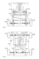
- FIG. 4 is a schematic structural view showing the embodiment disclosed in FIG. 1 being further formed as a four wheel drive system;
- the output end transmission devices (T100), (T300) are individually installed between the output shaft of first transmission device (1011) of the first transmission device (T101) and the wheel set (W100) at the rear left side and the wheel set (W300) at the front left side of the loading end, the output end clutch device (CL100) is installed between the output end of the output end transmission device (T100) and the transmission wheel train of the left side wheel shaft (S101) connected with the wheel set (W100), and the output end clutch device (CL300) is installed between the output end of the output end transmission device (T300) and the transmission wheel train of the left right wheel shaft (S103) connected with the wheel set (W300), and the output end transmission devices (T200), (T400) are individually installed between the output shaft of first transmission device (1012) and the wheel set (W200) at the rear right side and the wheel set (W400) at the front right side, and the output end clutch device (CL200) is installed between the output end
- the structure of the output end clutch device (CL100), (CL200), (CL300), (CL400) includes:
- the mentioned output end clutch devices (CL100), (CL200) at the rear end of the common load body (L100) are necessary to be installed, and the output end clutch devices (CL300), (CL400) can be optionally installed according to actual needs;
- the outer wheel set having high rotational speed performs the flexibility transmission with differential rotation to the inner wheel set having low rotational speed through the flexibility transmission device (FC100), so that the rotational speed of the inner wheel set is lower than that of the outer wheel set but still equipped with the driving power; and when the differential speed operation for turning direction is performed at the wheel set (W300) at the front left side and the wheel set (W400) at the front right side of the loading end, through releasing the output end clutch device between the inner wheel set and the first transmission device (T101), the outer wheel set having high rotational speed performs the flexibility transmission with differential rotation to the inner wheel set having low rotational speed through the flexibility transmission device (FC100), so that the rotational speed of the inner wheel set is lower than that of the outer wheel set but still equipped with the driving power; and when the differential speed operation for turning direction is performed at the wheel set (W300) at the front left side and the wheel set (W400) at the front right side of the loading end, through releasing the output end clutch device between the inner wheel set and the first transmission device (T
- a direction changing signal sensor (S100) can be further installed, so when changing directions, the signal of the direction changing signal sensor (S100) can be sent to the control unit (ECU100) for controlling the relative speed ratio switching of the output end transmission device (T100) and the output end transmission device (T200), thereby enhancing the performance of the drive for changing direction;
- FIG. 5 is a schematic view illustrating a direction changing signal sensor (S100) being provided for sending a signal to a control unit (ECU100) for controlling the relative speed ratio switching between the output end transmission device (T100) and the output end transmission device (T200), according to one embodiment of the present invention
- the common load body (L100) is installed with a first transmission device (T101) driven by the rotary kinetic power of a rotary kinetic power source (P100), an output end transmission device (T100) is installed between an output shaft of first transmission device (1011) of the first transmission device (T101) and a left side wheel set (W100) of the loading end, and an output end clutch device (CL100) is installed at the input end of a left side wheel shaft (S101) combined with the wheel set (W100), and an output end transmission device (T200) is installed between an output shaft of first transmission device (1012) and a right side wheel set (W200), and an output end clutch device (CL200) is installed at the input end of a right side wheel shaft (S102) combined with the wheel set (W200), and dual end shafts of a flexibility transmission device (FC100) are respectively connected to the left side wheel shaft (S101) and the right side wheel shaft (S102), which mainly consists of:
- the structure of the output end clutch device (CL100), (CL200) includes:
- the outer wheel set having high rotational speed performs the flexibility transmission with differential rotation to the inner wheel set having low rotational speed through the flexibility transmission device (FC100), so that the rotational speed of the inner wheel set is lower than that of the outer wheel set but still equipped with the driving power.
- FIG. 1 to FIG. 5 are examples of the differential drive system having individual clutch control and mutual flexibility transmission, when being desired to adopt more loading end wheel sets, the same means disclosed above can be applied.
- the drive system disclosed from FIG. 1 to FIG. 5 can be applied in a vehicle or an industry-used, agriculture-used or specially-designed carrier with front wheel drive, or rear wheel drive, or four wheel drive, or multiple wheel drive or driven by belts installed at two sides.
- an output end transmission device composed of a stepped or continuous variable transmission having fixed speed ratio for acceleration or deceleration or changing direction can be further installed between the output end of the first transmission device (T101) and the individual loading end wheel set;
- the mentioned output end transmission device is composed of mechanical gear sets, or chain sets, pulley sets or linkage rod sets, and structured as a transmission device having fixed speed ratio for acceleration or deceleration or changing direction, or a manually-operated or automatic or semi-automatic speed ratio or belt type continuous variable transmission, or a hydraulic type torque converter.
- the location where the output end clutch device being individually installed between the output end of the first transmission device (T101) to the individual transmission wheel system of individual loading end wheel set includes one or more than one of followings, including:
- the mentioned output end clutch device include being controlled by manual force or centrifugal force, or controlled through the external operation interface, and driven by the electric force and/or magnetic force and/ or mechanical force and/or air pressure and/or hydraulic force for performing transmission engaging or releasing, and has a rotary input end and a rotary output end.
- a flexibility transmission device composed of the limited slip differential or the dual shaft connecting device having slip coupling torque can be further installed at the opposite locations horizontally and coaxially at two sides along the driving direction of the common load body (L100) and between the same transmission operation sets; when the differential operation is performed between the wheel shaft and wheel set at the left side and the wheel shaft and wheel set at the right side combined to the dual shafts of the flexibility transmission device, e.g.
- the flexibility transmission device includes the coupling torque dual shaft connecting device composed of the coupling device have slip damp, e.g.
- a flexibility transmission device formed with a dual shaft structure through fluid viscous effect, hydrodynamic damp effect, mechanical friction effect, electromagnetic vortex effect or power generation reverse torque effect, two rotating ends are respectively combined at: one or more than one of opposite locations horizontally and coaxially defined on the following transmission operation sets, including:
- the limited slip differential or the flexibility transmission device composed of the dual shaft connecting devices having slip coupling torque installed at the opposite locations horizontally and coaxially defined at two sides along the driving direction of the common load body (L100) and between the installed wheel sets and the drive operation sets can be all or partially installed.
Abstract
Description
- According to the present invention, the differential drive system having individual clutch control and mutual flexibility transmission utilizes the rotary kinetic power of a rotary kinetic power source to directly drive a first transmission device (T101), or through an input end clutch device (CL101) to drive the first transmission device (T101), and between the output end of the first transmission device (T101) and two or more than two loading wheel sets driven thereby, an output end transmission device is individually installed for driving the loading wheel sets arranged at two sides of a common load body (L100), so as to drive the combined common load body, and an individually-controlled output end clutch device is installed for driving the output end transmission device and the driven wheel set and the wheel shaft to perform engaging transmission or terminating transmission, and between the wheel shafts of the loading wheel sets coaxially at two lateral sides of the common load body (L100), a flexibility transmission device composed of a dual shaft connecting device having slip coupling torque is installed, so that when controlling one of the individually-controlled output end clutch device to perform engaging transmission and controlling the other output end clutch device coaxially at the opposite side to perform terminating transmission, through the flexibility transmission device performing the flexibility transmission with differential rotational speed from the engaging transmission side to the terminating transmission side, the rotational speed of the wheel set at the terminating transmission side of the output end clutch device is lower than that of the wheel set at the engaging transmission side, but still equipped with the driving power in a lower speed.
- When a conventional single power performs differential driving to two or more than two individual loads of a common load body, a differential wheel set is often used for achieving the function of forming differential speed, the mentioned means has a shortage of not being able to generate the torque differential between the two loads, or when a clutch device is released for driving an inner wheel, an disadvantage of no driving power applied to the inner wheel is caused.
- According to the present invention, the differential drive system having individual clutch control and mutual flexibility transmission utilizes the rotary kinetic power of a rotary kinetic power source to directly drive a first transmission device (T101), or through an input end clutch device (CL101) to drive the first transmission device (T101), and between the output end of the first transmission device (T101) and two or more than two loading wheel sets driven thereby, an output end transmission device is individually installed for driving the loading wheel sets arranged at two sides of a common load body (L100), so as to drive the combined common load body, and an individually-controlled output end clutch device is installed for driving the output end transmission device and the driven wheel set and the wheel shaft to perform engaging transmission or terminating transmission, and between the wheel shafts of the loading wheel sets coaxially at two lateral sides of the common load body (L100), a flexibility transmission device composed of a dual shaft connecting device having slip coupling torque is installed, so that when controlling one of the individually-controlled output end clutch device to perform engaging transmission and controlling the other output end clutch device coaxially at the opposite side to perform terminating transmission, through the flexibility transmission device performing the flexibility transmission with differential rotational speed from the engaging transmission side to the terminating transmission side, the rotational speed of the wheel set at the terminating transmission side of the output end clutch device is lower than that of the wheel set at the engaging transmission side, but still equipped with the driving power in a lower speed.
- According to a second aspect of the present invention, a differential drive system comprises: a first transmission device (T101) having an input for receiving rotary kinetic power from a rotary kinetic power source and a plurality of outputs; a plurality of load wheels (W100; W200); a plurality of individual transmission devices (T100; T200), each of the individual transmission devices being installed between a separate one of the outputs of the first transmission device (T101) and a separate one of the plurality of load wheels (W100; W200); a plurality of output end clutch devices (CL100, CL200), each one of the output end clutch devices being installed between an individual transmission device and its respective load wheel such that each output end clutch device can be individually controlled; a flexible transmission device (FC100) disposed between the plurality of load wheels (W100; W200) and including a slip coupling which is arranged so that, when one of the individually controlled output end clutch devices is engaged so as to permit power to be transmitted from an individual transmission device to its corresponding load wheel, and another of the output end clutch devices is disengaged to prevent transmission from its corresponding individual transmission device to its corresponding load wheel, rotational power is transmitted from the driven load wheel to the undriven load wheel via the flexible transmission device (FC100).
-
-
FIG. 1 is a schematic view showing the basic system structure according to the present invention. -
FIG. 2 is schematic view showing the system structure ofFIG. 1 wherein the output end clutch device being installed at the output end of the first transmission device (T101). -
FIG. 3 is a schematic view showing the installation locations of the flexibility transmission device in the system structure ofFIG. 1 . -
FIG. 4 is a schematic structural view showing the embodiment disclosed inFIG. 1 being further formed as a four wheel drive system. -
FIG. 5 is a schematic view illustrating a direction changing signal sensor (S100) being provided for sending a signal to a control unit (ECU100) for controlling the relative speed ratio switching between the output end transmission device (T100) and the output end transmission device (T200), according to one embodiment of the present invention. -
- B 100: Electric power source
- CL101: Input end clutch device
- CL100 · CL200 · CL300. CL400: Output end clutch device
- 1011 · 1012: Output shaft of first transmission device
- S100: Direction changing signal sensor
- S101 · S103: Left side wheel shaft
- S102 · S104 Right side wheel shaft
- ECU 100: Control unit
- L100: Common load body
- MI100: External operation interface
- P100: Rotary kinetic power source
- FC100 · FC200: Flexibility transmission device
- T101: First transmission device
- T100 · T200 · T300 · T400: Output end transmission device
- W100 · W200 · W300 · W400 : Wheel set
- When a conventional single power performs differential driving to two or more than two individual loads of a common load body, a differential wheel set is often used for achieving the function of forming differential speed, the mentioned means has a shortage of not being able to generate the torque differential between the two loads, or when a clutch device is released for driving an inner wheel, an disadvantage of no driving power applied to the inner wheel is caused.
- According to the present invention, the differential drive system having individual clutch control and mutual flexibility transmission utilizes the rotary kinetic power of a rotary kinetic power source to directly drive a first transmission device (T101), or through an input end clutch device (CL101) to drive the first transmission device (T101), and between the output end of the first transmission device (T101) and two or more than two loading wheel sets driven thereby, an output end transmission device is individually installed for driving the loading wheel sets arranged at two sides of a common load body (L100), so as to drive the combined common load body, and an individually-controlled output end clutch device is installed for driving the output end transmission device and the driven wheel set and the wheel shaft to perform engaging transmission or terminating transmission, and between the wheel shafts of the loading wheel sets axially defined at two lateral sides of the common load body (L100), a flexibility transmission device composed of a dual shaft connecting device having slip coupling torque is installed, so that when controlling one of the individually-controlled output end clutch device to perform engaging transmission and controlling the other output end clutch device coaxially at the opposite side to perform terminating transmission, through the flexibility transmission device performing the flexibility transmission with differential rotational speed from the engaging transmission side to the terminating transmission side, the rotational speed of the wheel set at the terminating transmission side of the output end clutch device is lower than that of the wheel set at the engaging transmission side, but still equipped with the driving power in a lower speed.
- Several embodiments for illustrating the present invention are as followings:
-
FIG. 1 is a schematic view showing the basic system structure according to the present invention; - As shown in
FIG. 1 , the common load body (L100) is installed with a first transmission device (T101) driven by the rotary kinetic power of a rotary kinetic power source (P100), an output end transmission device (T100) is installed between an output shaft of first transmission device (1011) of the first transmission device (T101) and a left side wheel set (W100) of the loading end, and an output end clutch device (CL100) is installed at the input end of a left side wheel shaft (S101) combined with the wheel set (W100), and an output end transmission device (T200) is installed between an output shaft of first transmission device (1012) and a right side wheel set (W200), and an output end clutch device (CL200) is installed at the input end of a right side wheel shaft (S102) combined with the wheel set (W200), and dual end shafts of a flexibility transmission device (FC100) are respectively connected to the left side wheel shaft (5101) and the right side wheel shaft (S102), which mainly consists of: - -rotary kinetic power source (P100): constituted by a power source outputting kinetic power through rotation, e.g. an internal combustion engine, external combustion engine, spring power source, hydraulic power source, pressure power source, flywheel power source or manual force, or animal force, wind power source, and/or composed of a AC or DC, brush or brushless, synchronous or non-synchronous, internal rotating or external rotating type rotary motor installed with relative control devices and electrically driven by power supply and/or storage device; the output end thereof includes outputting directly or outputting through a clutch device;
- -input end clutch device (CL101): installed between the output end of the rotary kinetic power source (P100) and the input end of the first transmission device (T101), capable of controlling the rotary kinetic power source (P100) to control the transmission or termination of the rotary kinetic power to the first transmission device (T101); the input end clutch device (CL101) includes being controlled by manual force or centrifugal force, or being controlled through the external operation interface (MI100), and formed as a clutch device or structure driven by electric force and/or magnetic force and/or mechanical force and/or air pressure and/or hydraulic force for performing transmission engaging or releasing, and having a rotary input end and a rotary output end; the input end clutch device (CL101) can be optionally installed according to actual needs;
- -first transmission device (T101): constituted by a transmission device having fixed speed ratio or variable speed ratio or continuous variable speed and consisted of mechanical gear sets, or chain sets or pulley sets or linkage rod sets; installed between the rotary kinetic power source (P100) and the input ends of the output end transmission device (T100) and the output end transmission device (T200), including a single side output shaft for driving all wheel sets, or an output shaft of first transmission device (1011) and an output shaft of first transmission device (1012) having output shafts at two sides, so that the wheel sets installed at two sides of the common load body (L100) can be respectively driven through the output end transmission device (T100) and the output end transmission device (T200);
- -external operation interface (MI100): related to a linear analog type, or digital type, or hybrid type external control device, constituted by a operation mechanisms and/or electromechanical devices, and/or solid state electric circuits which are controlled by manual force, mechanical force or electric power,, provided for controlling the operation state of the rotary kinetic power source (P100), and/or controlling the operation of the flexibility transmission device (FC100) and/or the output end transmission device (T100), the output end transmission device (T200), and/or the output end clutch device (CL100), the output end clutch device (CL200) and the input end clutch device (CL101);
- -flexibility transmission device (FC100): constituted by a limited slip differential or a dual shaft connecting device having slip damp coupling torque, including a flexibility transmission device having dual shaft structure and formed through fluid viscous effect, hydrodynamic damp effect, mechanical friction effect, electromagnetic vortex effect or power generation reverse torque effect; wherein two rotating ends thereof are respectively connected to the left side wheel shaft (S101) combined with the wheel set (W100) at the left side of the loading end, and the right side wheel shaft (S102) combined with the wheel set (W200) at the right side; during the driving operation, because the unstable operation caused by the individual load varying at the left or the right sides of the loading end, the slip damp coupling torque of the flexibility transmission device (FC100) installed between the wheel sets at the right and the left sides can perform mutual kinetic power transmission;
- -output end transmission device (T100), (T200): the input end of the output end transmission device (T100) is driven by the rotary kinetic power from the output shaft of first transmission device (1011), and the output end thereof is served to drive the left side wheel set (W100) of the loading end; the input end of the output end transmission device (T200) is driven by the rotary kinetic power from the output shaft of first transmission device (1012), and the output end thereof is served to drive the right side wheel set (W200); the output end transmission device (T100) and the output end transmission device (T200) are consisted of mechanical gear sets, or chain sets or pulley sets or linkage rod sets, and composed of a transmission device having fixed speed ratio for acceleration or deceleration or changing direction, or a manually-operated or automatic or semi-automatic speed ratio varying or belt type continuous variable transmission, or a hydraulic torque converter; the output end transmission devices (T100), (T200) can be optionally installed according to actual needs;
- -output end clutch device (CL100), (CL200): the output end clutch device (CL100) is installed at the input end of the left side wheel shaft (S101) connected with the wheel set (W100) for controlling the rotary kinetic power outputted to the wheel set (W100); the output end clutch device (CL200) is installed at the input end of the right side wheel shaft (S102) connected with the wheel set (W200), for controlling the rotary kinetic power outputted to the wheel set (W200); the output end clutch device (CL100) and the output end clutch device (CL200) include being controlled by manual force or centrifugal force, or controlled by the external operation interface (MI100); or a clutch device or structure having function of performing transmission engaging or releasing while being driven by electric force and/or magnetic force and/ or mechanical force and/or air pressure and/or hydraulic force, and has a rotary input end and a rotary output end; the output end clutch device can further include a function of being driven by electric force and/or magnetic force and/or mechanical force and/or air pressure and/or hydraulic force for controlling the coupling torque between engaging and releasing, e.g. an electromagnetic wet type multi-plate clutch device controlling coupling torque through exciting current, or a wet type multi-plate clutch device driven by mechanical force and/or pressure and/or hydraulic force;
- The structure of the output end clutch device (CL100), (CL200) includes:
- (1) a clutch device or structure driven by the electric force and/or magnetic force and/or mechanical force and/or air pressure and/or hydraulic force for performing transmission engaging or releasing;
- (2) driven by the electric force and/or magnetic force and/ or mechanical force and/or air pressure and/or hydraulic force for linearly controlling the continuous coupling torque between transmission engaging and releasing;
- (3) driven by the electric force and/or magnetic force and/ or mechanical force and/or air pressure and/or hydraulic force for performing transmission engaging or releasing, and having torque limited coupling function which is smaller than the engaging torque, after being released;
- (4) driven by the electric force and/or magnetic force and/ or mechanical force and/or air pressure and/or hydraulic force for performing transmission engaging or releasing, and having a linear damp function which is smaller than the engaging torque and is increased while the rotation differential is increased, after being released;
- (5) driven by the electric force and/or magnetic force and/ or mechanical force and/or air pressure and/or hydraulic force for performing transmission engaging or releasing, and having a linear damp function which is smaller than the engaging torque and is reduced while the rotation differential is increased, after being released;
- (6) (1) to (5) including a radial clutch device;
- (7) (1) to (5) including an axial clutch device;
- -common load body (L100) can be installed with one or more than one non-powered wheels according to actual needs;
- By operating the mentioned devices, when the common load body (L100) is driven by the rotary kinetic power source (P100) to operate, and differential speed operation for turning direction is performed at the wheel set (W100) at the left side and the wheel set (W200) at the right side of the loading end, through releasing the output end clutch device between the inner wheel set and the first transmission device (T101), the outer wheel set having high rotational speed performs the flexibility transmission with differential rotation to the inner wheel set having low rotational speed through the flexibility transmission device (FC100), so that the rotational speed of the inner wheel set is lower than that of the outer wheel set but still equipped with the driving power.
-
FIG. 2 is schematic view showing the system structure ofFIG. 1 wherein the output end clutch device being installed at the output end of the first transmission device (T101); - As shown in
FIG. 2 , in the embodiment disclosed inFIG. 1 , the output end clutch device (CL100) is installed at the output shaft of first transmission device (1011); the output end clutch device (CL200) is installed at the output shaft of first transmission device (1022), which mainly consists of: - -rotary kinetic power source (P100): constituted by a power source outputting kinetic power through rotation, e.g. an internal combustion engine, external combustion engine, spring power source, hydraulic power source, pressure power source, flywheel power source or manual force, or animal force, wind power source, and/or composed of a AC or DC, brush or brushless, synchronous or non-synchronous, internal rotating or external rotating type rotary motor installed with relative control devices and electrically driven by power supply and/or storage device; the output end thereof includes outputting directly or outputting through a clutch device;
- -input end clutch device (CL101): installed between the output end of the rotary kinetic power source (P100) and the input end of the first transmission device (T101), capable of controlling the rotary kinetic power source (P100) to control the transmission or termination of the rotary kinetic power to the first transmission device (T101); the input end clutch device (CL101) includes being controlled by manual force or centrifugal force, or being controlled through the external operation interface (MI100), and formed as a clutch device or structure driven by electric force and/or magnetic force and/or mechanical force and/or air pressure and/or hydraulic force for performing transmission engaging or releasing, and having a rotary input end and a rotary output end; the input end clutch device (CL101) can be optionally installed according to actual needs;
- -first transmission device (T101): constituted by a transmission device having fixed speed ratio or variable speed ratio or continuous variable speed and consisted of mechanical gear sets, or chain sets or pulley sets or linkage rod sets; installed between the rotary kinetic power source (P100) and the input ends of the output end transmission device (T100) and the output end transmission device (T200), including a single side output shaft for driving all wheel sets, or an output shaft of first transmission device (1011) and an output shaft of first transmission device (1012) having output shafts at two sides, so that the wheel sets installed at two sides of the common load body (L100) can be respectively driven through the output end transmission device (T100) and the output end transmission device (T200);
- -external operation interface (MI100): related to a linear analog type, or digital type, or hybrid type external control device, constituted by a operation mechanisms and/or electromechanical devices, and/or solid state electric circuits which are controlled by manual force, mechanical force or electric power, provided for controlling the operation state of the rotary kinetic power source (P100), and/or controlling the operation of the flexibility transmission device (FC100) and/or the output end transmission device (T100), the output end transmission device (T200), and/or the output end clutch device (CL100), the output end clutch device (CL200) and the input end clutch device (CL101);
- -flexibility transmission device (FC100): constituted by a limited slip differential or a dual shaft connecting device having slip damp coupling torque, including a flexibility transmission device having dual shaft structure and formed through fluid viscous effect, hydrodynamic damp effect, mechanical friction effect, electromagnetic vortex effect or power generation reverse torque effect; two rotating ends thereof are respectively connected to the left side wheel shaft (S101) combined with the wheel set (W100) at the left side of the loading end, and the right side wheel shaft (S102) combined with the wheel set (W200) at the right side; during the driving operation, because the unstable operation caused by the individual load varying at the left or the right sides of the loading end, the slip damp coupling torque of the flexibility transmission device (FC100) installed between the wheel sets at the right and the left sides can perform mutual kinetic power transmission;
- -output end transmission device (T100), (T200): the output end of the output end transmission device (T100) is served to drive the left side wheel set (W100) of the loading end, and the input end thereof is driven by the rotary kinetic power from the output shaft of first transmission device (1011); the output end of the output end transmission device (T200) is served to drive the right side wheel set (W200), and the input end thereof is driven by the rotary kinetic power from the output shaft of first transmission device (1012); the output end transmission device (T100) and the output end transmission device (T200) are consisted of mechanical gear sets, or chain sets or pulley sets or linkage rod sets, and composed of a transmission device having fixed speed ratio for acceleration or deceleration or changing direction, or a manually-operated or automatic or semi-automatic speed ratio varying or belt type continuous variable transmission, or a hydraulic torque converter; the output end transmission devices (T100), (T200) can be optionally installed according to actual needs;
- -output end clutch device (CL100), (CL200): the output end clutch device (CL100) is installed at the output end of the output shaft of first transmission device (1011) for controlling the rotation kinetic power outputted to the wheel set (W100), and the output end clutch device (CL200) is installed at the output end of the output shaft of first transmission device (1012) for controlling the rotary kinetic power outputted to the wheel set (W200); the output end clutch device (CL100) and the output end clutch device (CL200) include being controlled by manual force or centrifugal force, or controlled by the external operation interface (MI100); or a clutch device or structure having function of performing transmission engaging or releasing while being driven by electric force and/or magnetic force and/ or mechanical force and/or air pressure and/or hydraulic force, and has a rotary input end and a rotary output end; the output end clutch device can further include a function of being driven by electric force and/or magnetic force and/or mechanical force and/or air pressure and/or hydraulic force for controlling the coupling torque between engaging and releasing, e.g. an electromagnetic wet type multi-plate clutch device controlling coupling torque through exciting current, or a wet type multi-plate clutch device driven by mechanical force and/or pressure and/or hydraulic force;
- The structure of the output end clutch device (CL100), (CL200) includes:
- (1) a clutch device or structure driven by the electric force and/or magnetic force and/ or mechanical force and/or air pressure and/or hydraulic force for performing transmission engaging or releasing;
- (2) driven by the electric force and/or magnetic force and/ or mechanical force and/or air pressure and/or hydraulic force for linearly controlling the continuous coupling torque between transmission engaging and releasing;
- (3) driven by the electric force and/or magnetic force and/ or mechanical force and/or air pressure and/or hydraulic force for performing transmission engaging or releasing, and having torque limited coupling function which is smaller than the engaging torque, after being released;
- (4) driven by the electric force and/or magnetic force and/ or mechanical force and/or air pressure and/or hydraulic force for performing transmission engaging or releasing, and having a linear damp function which is smaller than the engaging torque and is increased while the rotation differential is increased, after being released;
- (5) driven by the electric force and/or magnetic force and/ or mechanical force and/or air pressure and/or hydraulic force for performing transmission engaging or releasing, and having a linear damp function which is smaller than the engaging torque and is reduced while the rotation differential is increased, after being released;
- (6) (1) to (5) including a radial clutch device;
- (7) (1) to (5) including an axial clutch device;
- -common load body (L100) can be installed with one or more than one non-powered wheels according to actual needs;
- By operating the mentioned devices, when the common load body (L100) is driven by the rotary kinetic power source (P100) to operate, and differential speed operation for turning direction is performed at the wheel set (W100) at the left side and the wheel set (W200) at the right side of the loading end, through releasing the output end clutch device between the inner wheel set and the first transmission device (T101), the outer wheel set having high rotational speed performs the flexibility transmission with differential rotation to the inner wheel set having low rotational speed through the flexibility transmission device (FC100), so that the rotational speed of the inner wheel set is lower than that of the outer wheel set but still equipped with the driving power.
-
FIG. 3 is a schematic view showing the installation locations of the flexibility transmission device in the system structure ofFIG. 1 ; - As shown in
FIG. 3 , in the embodiment disclosed inFIG. 1 , the flexibility transmission device (FC100) is installed between the left side wheel shaft (S101) and the right side wheel shaft (S102), or installed between the input ends of the output end transmission device (T100) and the output end transmission device (T200), or installed between internal transmission structures of the output end transmission device itself, which mainly consists of: - -rotary kinetic power source (P100): constituted by a power source outputting kinetic power through rotation, e.g. an internal combustion engine, external combustion engine, spring power source, hydraulic power source, pressure power source, flywheel power source or manual force, or animal force, wind power source, and/or composed of a AC or DC, brush or brushless, synchronous or non-synchronous, internal rotating or external rotating type rotary motor installed with relative control devices and electrically driven by power supply and/or storage device; the output end thereof includes outputting directly or outputting through a clutch device;
- -input end clutch device (CL101): installed between the output end of the rotary kinetic power source (P100) and the input end of the first transmission device (T101), capable of controlling the rotary kinetic power source (P100) to control the transmission or termination of the rotary kinetic power to the first transmission device (T101); the input end clutch device (CL101) includes being controlled by manual force or centrifugal force, or being controlled through the external operation interface (MI100), and formed as a clutch device or structure driven by electric force and/or magnetic force and/or mechanical force and/or air pressure and/or hydraulic force for performing transmission engaging or releasing, and having a rotary input end and a rotary output end; the input end clutch device (CL101) can be optionally installed according to actual needs;
- -first transmission device (T101): constituted by a transmission device having fixed speed ratio or variable speed ratio or continuous variable speed and consisted of mechanical gear sets, or chain sets or pulley sets or linkage rod sets; installed between the rotary kinetic power source (P100) and the input ends of the output end transmission device (T100) and the output end transmission device (T200), including a single side output shaft for driving all wheel sets, or an output shaft of first transmission device (1011) and an output shaft of first transmission device (1012) having output shafts at two sides, so that the wheel sets installed at two sides of the common load body (L100) can be respectively driven through the output end transmission device (T100) and the output end transmission device (T200);
- -external operation interface (MI100): related to a linear analog type, or digital type, or hybrid type external control device, constituted by a operation mechanisms and/or electromechanical devices, and/or solid state electric circuits which are controlled by manual force, mechanical force or electric power, provided for controlling the operation state of the rotary kinetic power source (P100), and/or controlling the operation of the flexibility transmission device (FC100) and/or the output end transmission device (T100), the output end transmission device (T200), and/or the output end clutch device (CL100), the output end clutch device (CL200) and the input end clutch device (CL101),
- -flexibility transmission device (FC100): constituted by a limited slip differential or a dual shaft connecting device having slip damp coupling torque, including a flexibility transmission device having dual shaft structure and formed through fluid viscous effect, hydrodynamic damp effect, mechanical friction effect, electromagnetic vortex effect or power generation reverse torque effect; two rotating ends thereof are respectively connected to the left side wheel shaft (S101) combined with the wheel set (W100) at the left side of the loading end, and the right side wheel shaft (S102) combined with the wheel set (W200) at the right side, or connected between the transmission components having the same rotational speed while being in the normal straight running state installed in the transmission wheel train of the output end transmission device (T100) and the output end transmission device (T200); during the driving operation, because the unstable operation caused by the individual load varying at the left or the right sides of the loading end, the slip damp coupling torque of the flexibility transmission device (FC100) installed between the wheel sets at the right and the left sides can perform mutual kinetic power transmission;
- -output end transmission device (T100), (T200): the output end of the output end transmission device (T100) is served to drive the left side wheel set (W100) of the loading end, and the input end thereof is driven by the rotary kinetic power from the output shaft of first transmission device (1011); the output end of the output end transmission device (T200) is served to drive the right side wheel set (W200), and the input end thereof is driven by the rotary kinetic power from the output shaft of first transmission device (1012); the output end transmission device (T100) and the output end transmission device (T200) are consisted of mechanical gear sets, or chain sets or pulley sets or linkage rod sets, and composed of a transmission device having fixed speed ratio for acceleration or deceleration or changing direction, or a manually-operated or automatic or semi-automatic speed ratio varying or belt type continuous variable transmission, or a hydraulic torque converter; the output end transmission devices (T100), (T200) can be optionally installed according to actual needs;
- -output end clutch device (CL100), (CL200): the output end clutch device (CL100) is installed at the output end of the output shaft of first transmission device (1011) for controlling the rotation kinetic power outputted to the wheel set (W100), and the output end clutch device (CL200) is installed at the output end of the output shaft of first transmission device (1012) for controlling the rotary kinetic power outputted to the wheel set (W200); the output end clutch device (CL100) and the output end clutch device (CL200) include being controlled by manual force or centrifugal force, or controlled by the external operation interface (MI100); or a clutch device or structure having function of performing transmission engaging or releasing while being driven by electric force and/or magnetic force and/ or mechanical force and/or air pressure and/or hydraulic force, and has a rotary input end and a rotary output end; the output end clutch device can further include a function of being driven by electric force and/or magnetic force and/or mechanical force and/or air pressure and/or hydraulic force for controlling the coupling torque between engaging and releasing, e.g. an electromagnetic wet type multi-plate clutch device controlling coupling torque through exciting current, or a wet type multi-plate clutch device driven by mechanical force and/or pressure and/or hydraulic force;
- The structure of the output end clutch device (CL100), (CL200) includes:
- (1) a clutch device or structure driven by the electric force and/or magnetic force and/ or mechanical force and/or air pressure and/or hydraulic force for performing transmission engaging or releasing;
- (2) driven by the electric force and/or magnetic force and/ or mechanical force and/or air pressure and/or hydraulic force for linearly controlling the continuous coupling torque between transmission engaging and releasing;
- (3) driven by the electric force and/or magnetic force and/ or mechanical force and/or air pressure and/or hydraulic force for performing transmission engaging or releasing, and having torque limited coupling function which is smaller than the engaging torque, after being released;
- (4) driven by the electric force and/or magnetic force and/ or mechanical force and/or air pressure and/or hydraulic force for performing transmission engaging or releasing, and having a linear damp function which is smaller than the engaging torque and is increased while the rotation differential is increased, after being released;
- (5) driven by the electric force and/or magnetic force and/ or mechanical force and/or air pressure and/or hydraulic force for performing transmission engaging or releasing, and having a linear damp function which is smaller than the engaging torque and is reduced while the rotation differential is increased, after being released;
- (6) (1) to (5) including a radial clutch device;
- (7) (1) to (5) including an axial clutch device;
- -common load body (L100) can be installed with one or more than one non-powered wheels according to actual needs;
- By operating the mentioned devices, when the common load body (L100) is driven by the rotary kinetic power source (P100) to operate, and differential speed operation for turning direction is performed at the wheel set (W100) at the left side and the wheel set (W200) at the right side of the loading end, through releasing the output end clutch device between the inner wheel set and the first transmission device (T101), the outer wheel set having high rotational speed performs the flexibility transmission with differential rotation to the inner wheel set having low rotational speed through the flexibility transmission device (FC100), so that the rotational speed of the inner wheel set is lower than that of the outer wheel set but still equipped with the driving power.
-
FIG. 4 is a schematic structural view showing the embodiment disclosed inFIG. 1 being further formed as a four wheel drive system; - As shown in
FIG. 4 , in the embodiment disclosed inFIG. 1 , the output end transmission devices (T100), (T300) are individually installed between the output shaft of first transmission device (1011) of the first transmission device (T101) and the wheel set (W100) at the rear left side and the wheel set (W300) at the front left side of the loading end, the output end clutch device (CL100) is installed between the output end of the output end transmission device (T100) and the transmission wheel train of the left side wheel shaft (S101) connected with the wheel set (W100), and the output end clutch device (CL300) is installed between the output end of the output end transmission device (T300) and the transmission wheel train of the left right wheel shaft (S103) connected with the wheel set (W300), and the output end transmission devices (T200), (T400) are individually installed between the output shaft of first transmission device (1012) and the wheel set (W200) at the rear right side and the wheel set (W400) at the front right side, and the output end clutch device (CL200) is installed between the output end of the output end transmission device (T200) and the transmission wheel train of the right side wheel shaft (S102) connected with the wheel set (W200), and the output end clutch device (CL400) is installed between the output end of the output end transmission device (T400) and the transmission wheel train of the right side wheel shaft (S104) connected with the wheel set (W400), and the dual shafts of the flexibility transmission device (FC100) are respectively connected between the left side wheel shaft (S101) and the right side wheel shaft (S102), and the dual shafts of the flexibility transmission device (FC200) are respectively connected between the left side wheel shaft (S103) and the right side wheel shaft (S104), which mainly consists of: - -rotary kinetic power source (P100): constituted by a power source outputting kinetic power through rotation, e.g. an internal combustion engine, external combustion engine, spring power source, hydraulic power source, pressure power source, flywheel power source or manual force, or animal force, wind power source, and/or composed of a AC or DC, brush or brushless, synchronous or non-synchronous, internal rotating or external rotating type rotary motor installed with relative control devices and electrically driven by power supply and/or storage device; the output end thereof includes outputting directly or outputting through a clutch device;
- -input end clutch device (CL101): installed between the output end of the rotary kinetic power source (P100) and the input end of the first transmission device (T101), capable of controlling the rotary kinetic power source (P100) to control the transmission or termination of the rotary kinetic power to the first transmission device (T101); the input end clutch device (CL101) includes being controlled by manual force or centrifugal force, or being controlled through the external operation interface (MI100), and formed as a clutch device or structure driven by electric force and/or magnetic force and/or mechanical force and/or air pressure and/or hydraulic force for performing transmission engaging or releasing, and having a rotary input end and a rotary output end; the input end clutch device (CL101) can be optionally installed according to actual needs;
- -first transmission device (T101): constituted by a transmission device having fixed speed ratio or variable speed ratio or continuous variable speed and consisted of mechanical gear sets, or chain sets or pulley sets or linkage rod sets; installed between the rotary kinetic power source (P100) and the input ends of the output end transmission devices (T100), (T200), (T300), (T400), including a single side output shaft for driving all wheel sets, or an output shaft of first transmission device (1011) and an output shaft of first transmission device (1012) having output shafts at two sides, so that the wheel sets installed at two sides of the common load body (L100) can be respectively driven through the output end transmission devices (T100), (T200), (T300), (T400);
- -external operation interface (MI100): related to a linear analog type, or digital type, or hybrid type external control device, constituted by a operation mechanisms and/or electromechanical devices, and/or solid state electric circuits which are controlled by manual force, mechanical force or electric power, provided for controlling the operation state of the rotary kinetic power source (P100), and/or controlling the operation of the flexibility transmission device (FC100), (FC200) and/or the output end transmission devices (T100), (T200), (T300), (T400), and/or the output end clutch devices (CL100), (CL200), (CL300), (CL400) and the input end clutch device (CL101);
- -flexibility transmission device (FC100), (FC200): constituted by a limited slip differential or a dual shaft connecting device having slip damp coupling torque, including a flexibility transmission device having dual shaft structure and formed through fluid viscous effect, hydrodynamic damp effect, mechanical friction effect, electromagnetic vortex effect or power generation reverse torque effect; wherein two rotating ends of the flexibility transmission device (FC100) are respectively connected to the left side wheel shaft (S101) combined with the wheel set (W100) at the rear left side of the loading end, and the right side wheel shaft (S102) combined with the wheel set (W200) at the rear right side, and two rotating ends of the flexibility transmission device (FC200) are respectively connected to the left side wheel shaft (S103) combined with the wheel set (W300) at the front left side of the loading end, and the right side wheel shaft (S104) combined with the wheel set (W400) at the front right side; during the driving operation, because the unstable operation caused by the individual load varying at the left or the right sides of the loading end, the slip damp coupling torque of the flexibility transmission device (FC100) and/or the flexibility transmission device (FC200) installed between the wheel sets at the opposite right and left sides can perform mutual kinetic power transmission;
- -output end transmission device (T100), (T200), (T300), (T400): the output end of the output end transmission device (T100) is served to drive the wheel set (W100) at the rear left side of the loading end, and the input end thereof is driven by the rotary kinetic power from the output shaft of first transmission device (1011); the output end of the output end transmission device (T200) is served to drive the wheel set (W200) at the rear right side, and the input end thereof is driven by the rotary kinetic power from the output shaft of first transmission device (1012); the output end of the output end transmission device (T300) is served to drive the wheel set (W300) at the front left side of the loading end, and the input end thereof is driven by the rotary kinetic power from the output shaft of first transmission device (1011); the output end of the output end transmission device (T400) is served to drive the wheel set (W400) at the front right side, and the input end thereof is driven by the rotary kinetic power from the output shaft of first transmission device (1012); the output end transmission devices (T100), (T200), (T300), (T400) are consisted of mechanical gear sets, or chain sets or pulley sets or linkage rod sets, and composed of a transmission device having fixed speed ratio for acceleration or deceleration or changing direction, or a manually-operated or automatic or semi-automatic speed ratio varying or belt type continuous variable transmission, or a hydraulic torque converter; the output end transmission devices (T100), (T200) and/or (T300), (T400) can be optionally installed according to actual needs;
- -output end clutch device (CL100), (CL200), (CL300), (CL400): the output end clutch device (CL100) is installed between the output shaft of first transmission device (1011) and the transmission wheel train of the left side wheel shaft (S101) combined with the wheel set (W100) for controlling the rotary kinetic power outputted to the wheel set (W100), the output end clutch device (CL200) is installed between the output shaft of first transmission device (1012) and the transmission wheel train of the right side wheel shaft (S102) combined with the wheel set (W200) for controlling the rotary kinetic power outputted to the wheel set (W200), the output end clutch device (CL300) is installed between the output shaft of first transmission device (1011) and the transmission wheel train of the left side wheel shaft (S103) combined with the wheel set (W300) for controlling the rotation kinetic power outputted to the wheel set (W300), and the output end clutch device (CL400) is installed between the output shaft of first transmission device (1012) and the transmission wheel train of the right side wheel shaft (S104) combined with the wheel set (W400) for controlling the rotation kinetic power outputted to the wheel set (W400); the output end clutch devices (CL100), (CL200), (CL300), (CL400) include being controlled by manual force or centrifugal force, or controlled by the external operation interface (MI100), or a clutch device or structure having function of performing transmission engaging or releasing while being driven by electric force and/or magnetic force and/ or mechanical force and/or air pressure and/or hydraulic force, and has a rotary input end and a rotary output end; the output end clutch device can further include a function of being driven by electric force and/or magnetic force and/or mechanical force and/or air pressure and/or hydraulic force for controlling the coupling torque between engaging and releasing, e.g. an electromagnetic wet type multi-plate clutch device controlling coupling torque through exciting current, or a wet type multi-plate clutch device driven by mechanical force and/or pressure and/or hydraulic force;
- The structure of the output end clutch device (CL100), (CL200), (CL300), (CL400) includes:
- (1) a clutch device or structure driven by the electric force and/or magnetic force and/ or mechanical force and/or air pressure and/or hydraulic force for performing transmission engaging or releasing;
- (2) driven by the electric force and/or magnetic force and/ or mechanical force and/or air pressure and/or hydraulic force for linearly controlling the continuous coupling torque between transmission engaging and releasing;
- (3) driven by the electric force and/or magnetic force and/ or mechanical force and/or air pressure and/or hydraulic force for performing transmission engaging or releasing, and having torque limited coupling function which is smaller than the engaging torque, after being released;
- (4) driven by the electric force and/or magnetic force and/ or mechanical force and/or air pressure and/or hydraulic force for performing transmission engaging or releasing, and having a linear damp function which is smaller than the engaging torque and is increased while the rotation differential is increased, after being released;
- (5) driven by the electric force and/or magnetic force and/ or mechanical force and/or air pressure and/or hydraulic force for performing transmission engaging or releasing, and having a linear damp function which is smaller than the engaging torque and is reduced while the rotation differential is increased, after being released;
- (6) (1) to (5) including a radial clutch device;
- (7) (1) to (5) including an axial clutch device;
- The mentioned output end clutch devices (CL100), (CL200) at the rear end of the common load body (L100) are necessary to be installed, and the output end clutch devices (CL300), (CL400) can be optionally installed according to actual needs;
- -common load body (L100) can be installed with one or more than one non-powered wheels according to actual needs;
- By operating the mentioned devices, when the common load body (L100) is driven by the rotary kinetic power source (P100) to operate, and differential speed operation for turning direction is performed at the wheel set (W100) at the rear left side and the wheel set (W200) at the rear right side of the loading end, through releasing the output end clutch device between the inner wheel set and the first transmission device (T101), the outer wheel set having high rotational speed performs the flexibility transmission with differential rotation to the inner wheel set having low rotational speed through the flexibility transmission device (FC100), so that the rotational speed of the inner wheel set is lower than that of the outer wheel set but still equipped with the driving power; and when the differential speed operation for turning direction is performed at the wheel set (W300) at the front left side and the wheel set (W400) at the front right side of the loading end, through releasing the output end clutch device between the inner wheel set and the first transmission device (T101), the outer wheel set having high rotational speed performs the flexibility transmission with differential rotation to the inner wheel set having low rotational speed through the flexibility transmission device (FC200), so that the rotational speed of the inner wheel set is lower than that of the outer wheel set but still equipped with the driving power.
- According to the differential drive system having individual clutch control and mutual flexibility transmission, a direction changing signal sensor (S100) can be further installed, so when changing directions, the signal of the direction changing signal sensor (S100) can be sent to the control unit (ECU100) for controlling the relative speed ratio switching of the output end transmission device (T100) and the output end transmission device (T200), thereby enhancing the performance of the drive for changing direction;
-
FIG. 5 is a schematic view illustrating a direction changing signal sensor (S100) being provided for sending a signal to a control unit (ECU100) for controlling the relative speed ratio switching between the output end transmission device (T100) and the output end transmission device (T200), according to one embodiment of the present invention; - As shown in
FIG. 5 , the common load body (L100) is installed with a first transmission device (T101) driven by the rotary kinetic power of a rotary kinetic power source (P100), an output end transmission device (T100) is installed between an output shaft of first transmission device (1011) of the first transmission device (T101) and a left side wheel set (W100) of the loading end, and an output end clutch device (CL100) is installed at the input end of a left side wheel shaft (S101) combined with the wheel set (W100), and an output end transmission device (T200) is installed between an output shaft of first transmission device (1012) and a right side wheel set (W200), and an output end clutch device (CL200) is installed at the input end of a right side wheel shaft (S102) combined with the wheel set (W200), and dual end shafts of a flexibility transmission device (FC100) are respectively connected to the left side wheel shaft (S101) and the right side wheel shaft (S102), which mainly consists of: - -rotary kinetic power source (P100): constituted by a power source outputting kinetic power through rotation, e.g. an internal combustion engine, external combustion engine, spring power source, hydraulic power source, pressure power source, flywheel power source or manual force, or animal force, wind power source, and/or composed of a AC or DC, brush or brushless, synchronous or non-synchronous, internal rotating or external rotating type rotary motor installed with relative control devices and electrically driven by power supply and/or storage device; the output end thereof includes outputting directly or outputting through a clutch device;
- -input end clutch device (CL101): installed between the output end of the rotary kinetic power source (P100) and the input end of the first transmission device (T101), capable of controlling the rotary kinetic power source (P100) to control the transmission or termination of the rotary kinetic power to the first transmission device (T101); the input end clutch device (CL101) includes being controlled by manual force or centrifugal force, or being controlled through the external operation interface (MI100), and formed as a clutch device or structure driven by electric force and/or magnetic force and/or mechanical force and/or pressure and/or hydraulic force for performing transmission engaging or releasing, and having a rotary input end and a rotary output end; the input end clutch device (CL101) can be optionally installed according to actual needs;
- -first transmission device (T101): constituted by a transmission device having fixed speed ratio or variable speed ratio or continuous variable speed and consisted of mechanical gear sets, or chain sets or pulley sets or linkage rod sets; installed between the rotary kinetic power source (P100) and the input ends of the output end transmission device (T100) and the output end transmission device (T200), including a single side output shaft for driving all wheel sets, or an output shaft of first transmission device (1011) and an output shaft of first transmission device (1012) having output shafts at two sides, so that the wheel sets installed at two sides of the common load body (L100) can be respectively driven through the output end transmission device (T100) and the output end transmission device (T200);
- -external operation interface (MI100): related to a linear analog type, or digital type, or hybrid type external control device, constituted by a operation mechanisms and/or electromechanical devices, and/or solid state electric circuits which are controlled by manual force, mechanical force or electric power, provided for controlling the operation state of the rotary kinetic power source (P100), and/or controlling the operation of the flexibility transmission device (FC100) and/or the output end transmission device (T100), the output end transmission device (T200), and/or the output end clutch device (CL100), the output end clutch device (CL200) and the input end clutch device (CL101);
- -control unit (ECU100): constituted by electromechanical devices and/or electric circuit components and/or power semiconductors and/or microprocessors and software, for being connected to the electric power source (B100) and controlled by the external operation interface (MI100) or controlled by the direction changing signal sensor (S100) or operated through the signal of controlling system operation state, for controlling the operation state of the rotary kinetic power source (P100), and/or controlling the operation speed ratios of the multi-shift variable device (T100) and the multi-shift variable device (T200);
- - direction changing signal sensor (S100): defined as one or more than one physical sensors, for detecting signals relative to direction changing including one or more than one of following signals: a signal of direction changing degree from the steering machine, a signal of inclined angle of vehicle body, a signal of vehicle idling, a signal of upward/downward slope, a signal of acceleration or deceleration, and together with the signal of the external operation interface (MI100) to be transmitted to the control unit (ECU 100);
- -flexibility transmission device (FC100): constituted by a limited slip differential or a dual shaft connecting device having slip damp coupling torque, including a flexibility transmission device having dual shaft structure and formed through fluid viscous effect, hydrodynamic damp effect, mechanical friction effect, electromagnetic vortex effect or power generation reverse torque effect; wherein two rotating ends thereof are respectively connected to the left side wheel shaft (S101) combined with the wheel set (W100) at the left side of the loading end, and the right side wheel shaft (S102) combined with the wheel set (W200) at the right side; during the driving operation, because the unstable operation caused by the individual load varying at the left or the right sides of the loading end, the slip damp coupling torque of the flexibility transmission device (FC100) installed between the wheel sets at the right and the left sides can perform mutual kinetic power transmission;
- -output end transmission device (T100), (T200): the input end of the output end transmission device (T100) is driven by the rotary kinetic power from the output shaft of first transmission device (1011), and the output end thereof is served to drive the left side wheel set (W100) of the loading end; the input end of the output end transmission device (T200) is driven by the rotary kinetic power from the output shaft of first transmission device (1012), and the output end thereof is served to drive the right side wheel set (W200); the output end transmission device (T100) and the output end transmission device (T200) are consisted of mechanical gear sets, or chain sets or pulley sets or linkage rod sets, and composed of a transmission device having fixed speed ratio for acceleration or deceleration or changing direction, or a manually-operated or automatic or semi-automatic speed ratio varying or belt type continuous variable transmission, or a hydraulic torque converter; the output end transmission devices (T100), (T200) can be optionally installed according to actual needs;
- -output end clutch device (CL100), (CL200): the output end clutch device (CL100) is installed at the input end of the left side wheel shaft (S101) connected with the wheel set (W100) for controlling the rotary kinetic power outputted to the wheel set (W100); the output end clutch device (CL200) is installed at the input end of the right side wheel shaft (S102) connected with the wheel set (W200), for controlling the rotary kinetic power outputted to the wheel set (W200); the output end clutch device (CL100) and the output end clutch device (CL200) include being controlled by manual force or centrifugal force, or controlled by the external operation interface (MI100) and the control unit (ECU100); or a clutch device or structure having function of performing transmission engaging or releasing while being driven by electric force and/or magnetic force and/ or mechanical force and/or air pressure and/or hydraulic force, and has a rotary input end and a rotary output end; the output end clutch device can further include a function of being driven by electric force and/or magnetic force and/or mechanical force and/or air pressure and/or hydraulic force for controlling the coupling torque between engaging and releasing, e.g. an electromagnetic wet type multi-plate clutch device controlling coupling torque through exciting current, or a wet type multi-plate clutch device driven by mechanical force and/or pressure and/or hydraulic force;
- The structure of the output end clutch device (CL100), (CL200) includes:
- (1) a clutch device or structure driven by the electric force and/or magnetic force and/ or mechanical force and/or air pressure and/or hydraulic force for performing transmission engaging or releasing;
- (2) driven by the electric force and/or magnetic force and/ or mechanical force and/or air pressure and/or hydraulic force for linearly controlling the continuous coupling torque between transmission engaging and releasing;
- (3) driven by the electric force and/or magnetic force and/ or mechanical force and/or air pressure and/or hydraulic force for performing transmission engaging or releasing, and having torque limited coupling function which is smaller than the engaging torque, after being released;
- (4) driven by the electric force and/or magnetic force and/ or mechanical force and/or air pressure and/or hydraulic force for performing transmission engaging or releasing, and having a linear damp function which is smaller than the engaging torque and is increased while the rotation differential is increased, after being released;
- (5) driven by the electric force and/or magnetic force and/ or mechanical force and/or air pressure and/or hydraulic force for performing transmission engaging or releasing, and having a linear damp function which is smaller than the engaging torque and is reduced while the rotation differential is increased, after being released;
- (6) (1) to (5) including a radial clutch device;
- (7) (1) to (5) including an axial clutch device;
- -common load body (L100) can be installed with one or more than one non-powered wheels according to actual needs;
- By operating the mentioned devices, when the common load body (L100) is driven by the rotary kinetic power source (P100) to operate, and differential speed operation for turning direction is performed at the wheel set (W100) at the left side and the wheel set (W200) at the right side of the loading end, through releasing the output end clutch device between the inner wheel set and the first transmission device (T101), the outer wheel set having high rotational speed performs the flexibility transmission with differential rotation to the inner wheel set having low rotational speed through the flexibility transmission device (FC100), so that the rotational speed of the inner wheel set is lower than that of the outer wheel set but still equipped with the driving power.
- The disclosed
FIG. 1 to FIG. 5 are examples of the differential drive system having individual clutch control and mutual flexibility transmission, when being desired to adopt more loading end wheel sets, the same means disclosed above can be applied. - The drive system disclosed from
FIG. 1 to FIG. 5 can be applied in a vehicle or an industry-used, agriculture-used or specially-designed carrier with front wheel drive, or rear wheel drive, or four wheel drive, or multiple wheel drive or driven by belts installed at two sides. - According to the differential drive system having individual clutch control and mutual flexibility transmission, an output end transmission device composed of a stepped or continuous variable transmission having fixed speed ratio for acceleration or deceleration or changing direction can be further installed between the output end of the first transmission device (T101) and the individual loading end wheel set; the mentioned output end transmission device is composed of mechanical gear sets, or chain sets, pulley sets or linkage rod sets, and structured as a transmission device having fixed speed ratio for acceleration or deceleration or changing direction, or a manually-operated or automatic or semi-automatic speed ratio or belt type continuous variable transmission, or a hydraulic type torque converter.
- According to the differential drive system having individual clutch control and mutual flexibility transmission, the location where the output end clutch device being individually installed between the output end of the first transmission device (T101) to the individual transmission wheel system of individual loading end wheel set includes one or more than one of followings, including:
- (1) installed between the output end of the first transmission device (T101) and the input end of the individual output end transmission device;
- (2) installed at the input end of the output end transmission device;
- (3) installed at the output end of the output end transmission device;
- (4) installed in series between the internal power transmission components of the individual output end transmission device;
- (5) installed at the input end of the loading end wheel set;
- The mentioned output end clutch device include being controlled by manual force or centrifugal force, or controlled through the external operation interface, and driven by the electric force and/or magnetic force and/ or mechanical force and/or air pressure and/or hydraulic force for performing transmission engaging or releasing, and has a rotary input end and a rotary output end.
- According to the differential drive system having individual clutch control and mutual flexibility transmission, a flexibility transmission device composed of the limited slip differential or the dual shaft connecting device having slip coupling torque can be further installed at the opposite locations horizontally and coaxially at two sides along the driving direction of the common load body (L100) and between the same transmission operation sets; when the differential operation is performed between the wheel shaft and wheel set at the left side and the wheel shaft and wheel set at the right side combined to the dual shafts of the flexibility transmission device, e.g. the differential operation performed by the flexibility transmission device while the common load body (L100) is making a turn, through releasing the output end clutch device between the inner wheel set and the first transmission device (T101), the outer wheel set having high rotational speed performs the flexibility transmission with rotation differential to the inner wheel set having low rotational speed through the flexibility transmission device, so that the rotational speed of the inner wheel set is lower than that of the outer wheel set but still has the driving power; the flexibility transmission device includes the coupling torque dual shaft connecting device composed of the coupling device have slip damp, e.g. a flexibility transmission device formed with a dual shaft structure through fluid viscous effect, hydrodynamic damp effect, mechanical friction effect, electromagnetic vortex effect or power generation reverse torque effect, two rotating ends are respectively combined at: one or more than one of opposite locations horizontally and coaxially defined on the following transmission operation sets, including:
- (1) installed between the wheel shaft connecting the wheel set at the left side and the wheel set at the right side of the common load body (L100);
- (2) installed between the opposite input ends of the output end transmission devices at the left and the right sides of the common load body (L100);
- (3) installed between the opposite output ends of the output end clutch devices at the left and the right sides of the common load body (L100);
- (4) installed between the transmission components having the same rotational speed while being in the normal straight running state in the transmission wheel system of the output end transmission devices at the left and the right sides of the common load body (L100).
- According to the differential drive system having individual clutch control and mutual flexibility transmission, the limited slip differential or the flexibility transmission device composed of the dual shaft connecting devices having slip coupling torque installed at the opposite locations horizontally and coaxially defined at two sides along the driving direction of the common load body (L100) and between the installed wheel sets and the drive operation sets can be all or partially installed.
Claims (10)
- A differential drive system having individual clutch control and mutual flexibility transmission, which utilizes the rotary kinetic power of a rotary kinetic power source to directly drive a first transmission device (T101), or through an input end clutch device (CL101) to drive the first transmission device (T101), and between the output end of the first transmission device (T101) and two or more than two loading wheel sets driven thereby, an output end transmission device is individually installed for driving the loading wheel sets arranged at two sides of a common load body (L100), so as to drive the combined common load body, and an individually-controlled output end clutch device is installed for driving the output end transmission device and the driven wheel set and the wheel shaft to perform engaging transmission or terminating transmission, and between the wheel shafts of the loading wheel sets axially defined at two lateral sides of the common load body (L100), a flexibility transmission device composed of a dual shaft connecting device having slip coupling torque is installed, so that when controlling one of the individually-controlled output end clutch device to perform engaging transmission and controlling the other output end clutch device coaxially at the opposite side to perform terminating transmission, through the flexibility transmission device performing the flexibility transmission with differential rotational speed from the engaging transmission side to the terminating transmission side, the rotational speed of the wheel set at the terminating transmission side of the output end clutch device is lower than that of the wheel set at the engaging transmission side, but still equipped with the driving power in a lower speed.
- A differential drive system having individual clutch control and mutual flexibility transmission as claimed in claim 1, wherein the common load body (L100) is installed with a first transmission device (T101) driven by the rotary kinetic power of a rotary kinetic power source (P100), an output end transmission device (T100) is installed between an output shaft of first transmission device (1011) of the first transmission device (T101) and a left side wheel set (W100) of the loading end, and an output end clutch device (CL100) is installed at the input end of a left side wheel shaft (S101) combined with the wheel set (W100), and an output end transmission device (T200) is installed between an output shaft of first transmission device (1012) and a right side wheel set (W200), and an output end clutch device (CL200) is installed at the input end of a right side wheel shaft (S102) combined with the wheel set (W200), and dual end shafts of a flexibility transmission device (FC100) are respectively connected to the left side wheel shaft (S101) and the right side wheel shaft (S102), which mainly consists of:- -rotary kinetic power source (P100): constituted by a power source outputting kinetic power through rotation, e.g. an internal combustion engine, external combustion engine, spring power source, hydraulic power source, pressure power source, flywheel power source or manual force, or animal force, wind power source, and/or composed of a AC or DC, brush or brushless, synchronous or non-synchronous, internal rotating or external rotating type rotary motor installed with relative control devices and electrically driven by power supply and/or storage device; the output end thereof includes outputting directly or outputting through a clutch device;- -input end clutch device (CL101): installed between the output end of the rotary kinetic power source (P100) and the input end of the first transmission device (T101), capable of controlling the rotary kinetic power source (P100) to control the transmission or termination of the rotary kinetic power to the first transmission device (T101); the input end clutch device (CL101) includes being controlled by manual force or centrifugal force, or being controlled through the external operation interface (MI100), and formed as a clutch device or structure driven by electric force and/or magnetic force and/or mechanical force and/or air pressure and/or hydraulic force for performing transmission engaging or releasing, and having a rotary input end and a rotary output end; the input end clutch device (CL101) can be optionally installed according to actual needs;- -first transmission device (T101): constituted by a transmission device having fixed speed ratio or variable speed ratio or continuous variable speed and consisted of mechanical gear sets, or chain sets or pulley sets or linkage rod sets; installed between the rotary kinetic power source (P100) and the input ends of the output end transmission device (T100) and the output end transmission device (T200), including a single side output shaft for driving all wheel sets, or an output shaft of first transmission device (1011) and an output shaft of first transmission device (1012) having output shafts at two sides, so that the wheel sets installed at two sides of the common load body (L100) can be respectively driven through the output end transmission device (T100) and the output end transmission device (T200);- -external operation interface (MI100): related to a linear analog type, or digital type, or hybrid type external control device, constituted by a operation mechanisms and/or electromechanical devices, and/or solid state electric circuits which are controlled by manual force, mechanical force or electric power,, provided for controlling the operation state of the rotary kinetic power source (F100), and/or controlling the operation of the flexibility transmission device (FC100) and/or the output end transmission device (T100), the output end transmission device (T200), and/or the output end clutch device (CL100), the output end clutch device (CL200) and the input end clutch device (CL101);- -flexibility transmission device (FC100): constituted by a limited slip differential or a dual shaft connecting device having slip damp coupling torque, including a flexibility transmission device having dual shaft structure and formed through fluid viscous effect, hydrodynamic damp effect, mechanical friction effect, electromagnetic vortex effect or power generation reverse torque effect; wherein two rotating ends thereof are respectively connected to the left side wheel shaft (S101) combined with the wheel set (W100) at the left side of the loading end, and the right side wheel shaft (S102) combined with the wheel set (W200) at the right side; during the driving operation, because the unstable operation caused by the individual load varying at the left or the right sides of the loading end, the slip damp coupling torque of the flexibility transmission device (FC100) installed between the wheel sets at the right and the left sides can perform mutual kinetic power transmission;- -output end transmission device (T100), (T200): the input end of the output end transmission device (T100) is driven by the rotary kinetic power from the output shaft of first transmission device (1011), and the output end thereof is served to drive the left side wheel set (W100) of the loading end; the input end of the output end transmission device (T200) is driven by the rotary kinetic power from the output shaft of first transmission device (1012), and the output end thereof is served to drive the right side wheel set (W200); the output end transmission device (T100) and the output end transmission device (T200) are consisted of mechanical gear sets, or chain sets or pulley sets or linkage rod sets, and composed of a transmission device having fixed speed ratio for acceleration or deceleration or changing direction, or a manually-operated or automatic or semi-automatic speed ratio varying or belt type continuous variable transmission, or a hydraulic torque converter; the output end transmission devices (T100), (T200) can be optionally installed according to actual needs;- -output end clutch device (CL100), (CL200): the output end clutch device (CL100) is installed at the input end of the left side wheel shaft (S101) connected with the wheel set (W100) for controlling the rotary kinetic power outputted to the wheel set (W100); the output end clutch device (CL200) is installed at the input end of the right side wheel shaft (S102) connected with the wheel set (W200), for controlling the rotary kinetic power outputted to the wheel set (W200); the output end clutch device (CL100) and the output end clutch device (CL200) include being controlled by manual force or centrifugal force, or controlled by the external operation interface (MI100); or a clutch device or structure having function of performing transmission engaging or releasing while being driven by electric force and/or magnetic force and/ or mechanical force and/or air pressure and/or hydraulic force, and has a rotary input end and a rotary output end; the output end clutch device can further include a function of being driven by electric force and/or magnetic force and/or mechanical force and/or air pressure and/or hydraulic force for controlling the coupling torque between engaging and releasing, e.g. an electromagnetic wet type multi-plate clutch device controlling coupling torque through exciting current, or a wet type multi-plate clutch device driven by mechanical force and/or pressure and/or hydraulic force;The structure of the output end clutch device (CL100), (CL200) includes:(1) a clutch device or structure driven by the electric force and/or magnetic force and/ or mechanical force and/or air pressure and/or hydraulic force for performing transmission engaging or releasing;(2) driven by the electric force and/or magnetic force and/ or mechanical force and/or air pressure and/or hydraulic force for linearly controlling the continuous coupling torque between transmission engaging and releasing;(3) driven by the electric force and/or magnetic force and/ or mechanical force and/or air pressure and/or hydraulic force for performing transmission engaging or releasing, and having torque limited coupling function which is smaller than the engaging torque, after being released;(4) driven by the electric force and/or magnetic force and/ or mechanical force and/or air pressure and/or hydraulic force for performing transmission engaging or releasing, and having a linear damp function which is smaller than the engaging torque and is increased while the rotation differential is increased, after being released;(5) driven by the electric force and/or magnetic force and/ or mechanical force and/or air pressure and/or hydraulic force for performing transmission engaging or releasing, and having a linear damp function which is smaller than the engaging torque and is reduced while the rotation differential is increased, after being released;(6) (1) to (5) including a radial clutch device;(7) (1) to (5) including an axial clutch device;- -common load body (L100) can be installed with one or more than one non-powered wheels according to actual needs;
By operating the mentioned devices, when the common load body (L100) is driven by the rotary kinetic power source (P100) to operate, and differential speed operation for turning direction is performed at the wheel set (W100) at the left side and the wheel set (W200) at the right side of the loading end, through releasing the output end clutch device between the inner wheel set and the first transmission device (T101), the outer wheel set having high rotational speed performs the flexibility transmission with differential rotation to the inner wheel set having low rotational speed through the flexibility transmission device (FC100), so that the rotational speed of the inner wheel set is lower than that of the outer wheel set but still equipped with the driving power. - A differential drive system having individual clutch control and mutual flexibility transmission as claimed in claim 2, wherein the output end clutch device (CL100) is installed at the output shaft of first transmission device (1011); the output end clutch device (CL200) is installed at the output shaft of first transmission device (1022), which mainly consists of:- -rotary kinetic power source (P100): constituted by a power source outputting kinetic power through rotation, e.g. an internal combustion engine, external combustion engine, spring power source, hydraulic power source, pressure power source, flywheel power source or manual force, or animal force, wind power source, and/or composed of a AC or DC, brush or brushless, synchronous or non-synchronous, internal rotating or external rotating type rotary motor installed with relative control devices and electrically driven by power supply and/or storage device; the output end thereof includes outputting directly or outputting through a clutch device;- -input end clutch device (CL101): installed between the output end of the rotary kinetic power source (P100) and the input end of the first transmission device (T101), capable of controlling the rotary kinetic power source (P100) to control the transmission or termination of the rotary kinetic power to the first transmission device (T101); the input end clutch device (CL101) includes being controlled by manual force or centrifugal force, or being controlled through the external operation interface (MI100), and formed as a clutch device or structure driven by electric force and/or magnetic force and/or mechanical force and/or air pressure and/or hydraulic force for performing transmission engaging or releasing, and having a rotary input end and a rotary output end; the input end clutch device (CL101) can be optionally installed according to actual needs;- -first transmission device (T101): constituted by a transmission device having fixed speed ratio or variable speed ratio or continuous variable speed and consisted of mechanical gear sets, or chain sets or pulley sets or linkage rod sets; installed between the rotary kinetic power source (P100) and the input ends of the output end transmission device (T100) and the output end transmission device (T200), including a single side output shaft for driving all wheel sets, or an output shaft of first transmission device (1011) and an output shaft of first transmission device (1012) having output shafts at two sides, so that the wheel sets installed at two sides of the common load body (L100) can be respectively driven through the output end transmission device (T100) and the output end transmission device (T200);- -external operation interface (MI100): related to a linear analog type, or digital type, or hybrid type external control device, constituted by a operation mechanisms and/or electromechanical devices, and/or solid state electric circuits which are controlled by manual force, mechanical force or electric power, provided for controlling the operation state of the rotary kinetic power source (P100), and/or controlling the operation of the flexibility transmission device (FC100) and/or the output end transmission device (T100), the output end transmission device (T200), and/or the output end clutch device (CL100), the output end clutch device (CL200) and the input end clutch device (CL101);- -flexibility transmission device (FC100): constituted by a limited slip differential or a dual shaft connecting device having slip damp coupling torque, including a flexibility transmission device having dual shaft structure and formed through fluid viscous effect, hydrodynamic damp effect, mechanical friction effect, electromagnetic vortex effect or power generation reverse torque effect; two rotating ends thereof are respectively connected to the left side wheel shaft (S101) combined with the wheel set (W100) at the left side of the loading end, and the right side wheel shaft (S102) combined with the wheel set (W200) at the right side; during the driving operation, because the unstable operation caused by the individual load varying at the left or the right sides of the loading end, the slip damp coupling torque of the flexibility transmission device (FC100) installed between the wheel sets at the right and the left sides can perform mutual kinetic power transmission;- -output end transmission device (T100), (T200): the output end of the output end transmission device (T100) is served to drive the left side wheel set (W100) of the loading end, and the input end thereof is driven by the rotary kinetic power from the output shaft of first transmission device (7011); the output end of the output end transmission device (T200) is served to drive the right side wheel set (W200), and the input end thereof is driven by the rotary kinetic power from the output shaft of first transmission device (1012); the output end transmission device (T100) and the output end transmission device (T200) are consisted of mechanical gear sets, or chain sets or pulley sets or linkage rod sets, and composed of a transmission device having fixed speed ratio for acceleration or deceleration or changing direction, or a manually-operated or automatic or semi-automatic speed ratio varying or belt type continuous variable transmission, or a hydraulic torque converter; the output end transmission devices (T100), (T200) can be optionally installed according to actual needs;- -output end clutch device (CL100), (CL200): the output end clutch device (CL100) is installed at the output end of the output shaft of first transmission device (1011) for controlling the rotation kinetic power outputted to the wheel set (W100), and the output end clutch device (CL200) is installed at the output end of the output shaft of first transmission device (1012) for controlling the rotary kinetic power outputted to the wheel set (W200); the output end clutch device (CL100) and the output end clutch device (CL200) include being controlled by manual force or centrifugal force, or controlled by the external operation interface (MI 100); or a clutch device or structure having function of performing transmission engaging or releasing while being driven by electric force and/or magnetic force and/ or mechanical force and/or air pressure and/or hydraulic force, and has a rotary input end and a rotary output end; the output end clutch device can further include a function of being driven by electric force and/or magnetic force and/or mechanical force and/or air pressure and/or hydraulic force for controlling the coupling torque between engaging and releasing, e.g. an electromagnetic wet type multi-plate clutch device controlling coupling torque through exciting current, or a wet type multi-plate clutch device driven by mechanical force and/or pressure and/or hydraulic force;
The structure of the output end clutch device (CL100), (CL200) includes:(1) a clutch device or structure driven by the electric force and/or magnetic force and/ or mechanical force and/or air pressure and/or hydraulic force for performing transmission engaging or releasing;(2) driven by the electric force and/or magnetic force and/ or mechanical force and/or air pressure and/or hydraulic force for linearly controlling the continuous coupling torque between transmission engaging and releasing;(3) driven by the electric force and/or magnetic force and/ or mechanical force and/or air pressure and/or hydraulic force for performing transmission engaging or releasing, and having torque limited coupling function which is smaller than the engaging torque, after being released;(4) driven by the electric force and/or magnetic force and/ or mechanical force and/or air pressure and/or hydraulic force for performing transmission engaging or releasing, and having a linear damp function which is smaller than the engaging torque and is increased while the rotation differential is increased, after being released;(5) driven by the electric force and/or magnetic force and/ or mechanical force and/or air pressure and/or hydraulic force for performing transmission engaging or releasing, and having a linear damp function which is smaller than the engaging torque and is reduced while the rotation differential is increased, after being released;(6) (1) to (5) including a radial clutch device;(7) (1) to (5) including an axial clutch device;--common load body (L100) can be installed with one or more than one non-powered wheels according to actual needs;
By operating the mentioned devices, when the common load body (L100) is driven by the rotary kinetic power source (P100) to operate, and differential speed operation for turning direction is performed at the wheel set (W100) at the left side and the wheel set (W200) at the right side of the loading end, through releasing the output end clutch device between the inner wheel set and the first transmission device (T101), the outer wheel set having high rotational speed performs the flexibility transmission with differential rotation to the inner wheel set having low rotational speed through the flexibility transmission device (FC100), so that the rotational speed of the inner wheel set is lower than that of the outer wheel set but still equipped with the driving power. - A differential drive system having individual clutch control and mutual flexibility transmission as claimed in claim 2, wherein the flexibility transmission device (FC100) is installed between the left side wheel shaft (S101) and the right side wheel shaft (S102), or installed between the input ends of the output end transmission device (T100) and the output end transmission device (T200), or installed between internal transmission structures of the output end transmission device itself, which mainly consists of:- -rotary kinetic power source (P100): constituted by a power source outputting kinetic power through rotation, e.g. an internal combustion engine, external combustion engine, spring power source, hydraulic power source, pressure power source, flywheel power source or manual force, or animal force, wind power source, and/or composed of a AC or DC, brush or brushless, synchronous or non-synchronous, internal rotating or external rotating type rotary motor installed with relative control devices and electrically driven by power supply and/or storage device; the output end thereof includes outputting directly or outputting through a clutch device;- -input end clutch device (CL101): installed between the output end of the rotary kinetic power source (P100) and the input end of the first transmission device (T101), capable of controlling the rotary kinetic power source (P100) to control the transmission or termination of the rotary kinetic power to the first transmission device (T101); the input end clutch device (CL101) includes being controlled by manual force or centrifugal force, or being controlled through the external operation interface (MI100), and formed as a clutch device or structure driven by electric force and/or magnetic force and/or mechanical force and/or air pressure and/or hydraulic force for performing transmission engaging or releasing, and having a rotary input end and a rotary output end; the input end clutch device (CL101) can be optionally installed according to actual needs;- -first transmission device (T101): constituted by a transmission device having fixed speed ratio or variable speed ratio or continuous variable speed and consisted of mechanical gear sets, or chain sets or pulley sets or linkage rod sets; installed between the rotary kinetic power source (P100) and the input ends of the output end transmission device (T100) and the output end transmission device (T200), including a single side output shaft for driving all wheel sets, or an output shaft of first transmission device (1011) and an output shaft of first transmission device (1012) having output shafts at two sides, so that the wheel sets installed at two sides of the common load body (L100) can be respectively driven through the output end transmission device (T100) and the output end transmission device (T200);- -external operation interface (MI100): related to a linear analog type, or digital type, or hybrid type external control device, constituted by a operation mechanisms and/or electromechanical devices, and/or solid state electric circuits which are controlled by manual force, mechanical force or electric power, provided for controlling the operation state of the rotary kinetic power source (P100), and/or controlling the operation of the flexibility transmission device (FC100) and/or the output end transmission device (T100), the output end transmission device (T200), and/or the output end clutch device (CL100), the output end clutch device (CL200) and the input end clutch device (CL101);- -flexibility transmission device (FC100): constituted by a limited slip differential or a dual shaft connecting device having slip damp coupling torque, including a flexibility transmission device having dual shaft structure and formed through fluid viscous effect, hydrodynamic damp effect, mechanical friction effect, electromagnetic vortex effect or power generation reverse torque effect; two rotating ends thereof are respectively connected to the left side wheel shaft (S101) combined with the wheel set (W100) at the left side of the loading end, and the right side wheel shaft (S102) combined with the wheel set (W200) at the right side, or connected between the transmission components having the same rotational speed while being in the normal straight running state installed in the transmission wheel train of the output end transmission device (T100) and the output end transmission device (T200); during the driving operation, because the unstable operation caused by the individual load varying at the left or the right sides of the loading end, the slip damp coupling torque of the flexibility transmission device (FC100) installed between the wheel sets at the right and the left sides can perform mutual kinetic power transmission;- -output end transmission device (T100), (T200): the output end of the output end transmission device (T100) is served to drive the left side wheel set (W100) of the loading end, and the input end thereof is driven by the rotary kinetic power from the output shaft of first transmission device (1011); the output end of the output end transmission device (T200) is served to drive the right side wheel set (W200), and the input end thereof is driven by the rotary kinetic power from the output shaft of first transmission device (1012); the output end transmission device (T100) and the output end transmission device (T200) are consisted of mechanical gear sets, or chain sets or pulley sets or linkage rod sets, and composed of a transmission device having fixed speed ratio for acceleration or deceleration or changing direction, or a manually-operated or automatic or semi-automatic speed ratio varying or belt type continuous variable transmission, or a hydraulic torque converter; the output end transmission devices (T100), (T200) can be optionally installed according to actual needs;- -output end clutch device (CL100), (CL200): the output end clutch device (CL100) is installed at the output end of the output shaft of first transmission device (1011) for controlling the rotation kinetic power outputted to the wheel set (W100), and the output end clutch device (CL200) is installed at the output end of the output shaft of first transmission device (1012) for controlling the rotary kinetic power outputted to the wheel set (W200); the output end clutch device (CL100) and the output end clutch device (CL200) include being controlled by manual force or centrifugal force, or controlled by the external operation interface (MI100); or a clutch device or structure having function of performing transmission engaging or releasing while being driven by electric force and/or magnetic force and/ or mechanical force and/or air pressure and/or hydraulic force, and has a rotary input end and a rotary output end; the output end clutch device can further include a function of being driven by electric force and/or magnetic force and/or mechanical force and/or air pressure and/or hydraulic force for controlling the coupling torque between engaging and releasing, e.g. an electromagnetic wet type multi-plate clutch device controlling coupling torque through exciting current, or a wet type multi-plate clutch device driven by mechanical force and/or pressure and/or hydraulic force;
The structure of the output end clutch device (CL100), (CL200) includes:(1) a clutch device or structure driven by the electric force and/or magnetic force and/ or mechanical force and/or air pressure and/or hydraulic force for performing transmission engaging or releasing;(2) driven by the electric force and/or magnetic force and/ or mechanical force and/or air pressure and/or hydraulic force for linearly controlling the continuous coupling torque between transmission engaging and releasing;(3) driven by the electric force and/or magnetic force and/ or mechanical force and/or air pressure and/or hydraulic force for performing transmission engaging or releasing, and having torque limited coupling function which is smaller than the engaging torque, after being released;(4) driven by the electric force and/or magnetic force and/ or mechanical force and/or air pressure and/or hydraulic force for performing transmission engaging or releasing, and having a linear damp function which is smaller than the engaging torque and is increased while the rotation differential is increased, after being released;(5) driven by the electric force and/or magnetic force and/ or mechanical force and/or air pressure and/or hydraulic force for performing transmission engaging or releasing, and having a linear damp function which is smaller than the engaging torque and is reduced while the rotation differential is increased, after being released;(6) (1) to (5) including a radial clutch device;(7) (1) to (5) including an axial clutch device;- -common load body (L100) can be installed with one or more than one non-powered wheels according to actual needs;
By operating the mentioned devices, when the common load body (L100) is driven by the rotary kinetic power source (P100) to operate, and differential speed operation for turning direction is performed at the wheel set (W100) at the left side and the wheel set (W200) at the right side of the loading end, through releasing the output end clutch device between the inner wheel set and the first transmission device (T101), the outer wheel set having high rotational speed performs the flexibility transmission with differential rotation to the inner wheel set having low rotational speed through the flexibility transmission device (FC100), so that the rotational speed of the inner wheel set is lower than that of the outer wheel set but still equipped with the driving power. - A differential drive system having individual clutch control and mutual flexibility transmission as claimed in claim 2, wherein the output end transmission devices (T100), (T300) are individually installed between the output shaft of first transmission device (1011) of the first transmission device (T101) and the wheel set (W100) at the rear left side and the wheel set (W300) at the front left side of the loading end, the output end clutch device (CL100) is installed between the output end of the output end transmission device (T100) and the transmission wheel train of the left side wheel shaft (S101) connected with the wheel set (W100), and the output end clutch device (CL300) is installed between the output end of the output end transmission device (T300) and the transmission wheel train of the left right wheel shaft (S103) connected with the wheel set (W300), and the output end transmission devices (T200), (T400) are individually installed between the output shaft of first transmission device (1012) and the wheel set (W200) at the rear right side and the wheel set (W400) at the front right side, and the output end clutch device (CL200) is installed between the output end of the output end transmission device (T200) and the transmission wheel train of the right side wheel shaft (S102) connected with the wheel set (W200), and the output end clutch device (CL400) is installed between the output end of the output end transmission device (T400) and the transmission wheel train of the right side wheel shaft (S104) connected with the wheel set (W400), and the dual shafts of the flexibility transmission device (FC100) are respectively connected between the left side wheel shaft (S101) and the right side wheel shaft (S102), and the dual shafts of the flexibility transmission device (FC200) are respectively connected between the left side wheel shaft (S103) and the right side wheel shaft (S104), which mainly consists of:- -rotary kinetic power source (P100): constituted by a power source outputting kinetic power through rotation, e.g. an internal combustion engine, external combustion engine, spring power source, hydraulic power source, pressure power source, flywheel power source or manual force, or animal force, wind power source, and/or composed of a AC or DC, brush or brushless, synchronous or non-synchronous, internal rotating or external rotating type rotary motor installed with relative control devices and electrically driven by power supply and/or storage device; the output end thereof includes outputting directly or outputting through a clutch device;- -input end clutch device (CL101): installed between the output end of the rotary kinetic power source (P100) and the input end of the first transmission device (T101), capable of controlling the rotary kinetic power source (P100) to control the transmission or termination of the rotary kinetic power to the first transmission device (T101); the input end clutch device (CL101) includes being controlled by manual force or centrifugal force, or being controlled through the external operation interface (MI100), and formed as a clutch device or structure driven by electric force and/or magnetic force and/or mechanical force and/or air pressure and/or hydraulic force for performing transmission engaging or releasing, and having a rotary input end and a rotary output end; the input end clutch device (CL101) can be optionally installed according to actual needs;- -first transmission device (T101): constituted by a transmission device having fixed speed ratio or variable speed ratio or continuous variable speed and consisted of mechanical gear sets, or chain sets or pulley sets or linkage rod sets; installed between the rotary kinetic power source (P100) and the input ends of the output end transmission devices (T100), (T200), (T300), (T400), including a single side output shaft for driving all wheel sets, or an output shaft of first transmission device (1011) and an output shaft of first transmission device (1012) having output shafts at two sides, so that the wheel sets installed at two sides of the common load body (L100) can be respectively driven through the output end transmission devices (T100), (T200), (T300), (T400);- -external operation interface (MI100): related to a linear analog type, or digital type, or hybrid type external control device, constituted by a operation mechanisms and/or electromechanical devices, and/or solid state electric circuits which are controlled by manual force, mechanical force or electric power, provided for controlling the operation state of the rotary kinetic power source (P100), and/or controlling the operation of the flexibility transmission device (FC100), (FC200) and/or the output end transmission devices (T100), (T200), (T300), (T400), and/or the output end clutch devices (CL100), (CL200), (CL300), (CL400) and the input end clutch device (CL101);- -flexibility transmission device (FC100), (FC200): constituted by a limited slip differential or a dual shaft connecting device having slip damp coupling torque, including a flexibility transmission device having dual shaft structure and formed through fluid viscous effect, hydrodynamic damp effect, mechanical friction effect, electromagnetic vortex effect or power generation reverse torque effect; wherein two rotating ends of the flexibility transmission device (FC100) are respectively connected to the left side wheel shaft (S101) combined with the wheel set (W100) at the rear left side of the loading end, and the right side wheel shaft (S102) combined with the wheel set (W200) at the rear right side, and two rotating ends of the flexibility transmission device (FC200) are respectively connected to the left side wheel shaft (S103) combined with the wheel set (W300) at the front left side of the loading end, and the right side wheel shaft (S104) combined with the wheel set (W400) at the front right side; during the driving operation, because the unstable operation caused by the individual load varying at the left or the right sides of the loading end, the slip damp coupling torque of the flexibility transmission device (FC100) and/or the flexibility transmission device (FC200) installed between the wheel sets at the opposite right and left sides can perform mutual kinetic power transmission;- -output end transmission device (T100), (T200), (T300), (T400): the output end of the output end transmission device (T100) is served to drive the wheel set (W100) at the rear left side of the loading end, and the input end thereof is driven by the rotary kinetic power from the output shaft of first transmission device (11011); the output end of the output end transmission device (T200) is served to drive the wheel set (W200) at the rear right side, and the input end thereof is driven by the rotary kinetic power from the output shaft of first transmission device (1012); the output end of the output end transmission device (T300) is served to drive the wheel set (W300) at the front left side of the loading end, and the input end thereof is driven by the rotary kinetic power from the output shaft of first transmission device (1011); the output end of the output end transmission device (T400) is served to drive the wheel set (W400) at the front right side, and the input end thereof is driven by the rotary kinetic power from the output shaft of first transmission device (1012); the output end transmission devices (T100), (T200), (T300), (T400) are consisted of mechanical gear sets, or chain sets or pulley sets or linkage rod sets, and composed of a transmission device having fixed speed ratio for acceleration or deceleration or changing direction, or a manually-operated or automatic or semi-automatic speed ratio varying or belt type continuous variable transmission, or a hydraulic torque converter; the output end transmission devices (T100), (T200) and/or (T300), (T400) can be optionally installed according to actual needs;- -output end clutch device (CL100), (CL200), (CL300), (CL400): the output end clutch device (CL100) is installed between the output shaft of first transmission device (1011) and the transmission wheel train of the left side wheel shaft (S101) combined with the wheel set (W100) for controlling the rotary kinetic power outputted to the wheel set (W100), the output end clutch device (CL200) is installed between the output shaft of first transmission device (1012) and the transmission wheel train of the right side wheel shaft (S102) combined with the wheel set (W200) for controlling the rotary kinetic power outputted to the wheel set (W200), the output end clutch device (CL300) is installed between the output shaft of first transmission device (1011) and the transmission wheel train of the left side wheel shaft (S103) combined with the wheel set (W300) for controlling the rotation kinetic power outputted to the wheel set (W300), and the output end clutch device (CL400) is installed between the output shaft of first transmission device (1012) and the transmission wheel train of the right side wheel shaft (S104) combined with the wheel set (W400) for controlling the rotation kinetic power outputted to the wheel set (W400); the output end clutch devices (CL100), (CL200), (CL300), (CL400) include being controlled by manual force or centrifugal force, or controlled by the external operation interface (MI100), or a clutch device or structure having function of performing transmission engaging or releasing while being driven by electric force and/or magnetic force and/ or mechanical force and/or air pressure and/or hydraulic force, and has a rotary input end and a rotary output end; the output end clutch device can further include a function of being driven by electric force and/or magnetic force and/or mechanical force and/or air pressure and/or hydraulic force for controlling the coupling torque between engaging and releasing, e.g. an electromagnetic wet type multi-plate clutch device controlling coupling torque through exciting current, or a wet type multi-plate clutch device driven by mechanical force and/or pressure and/or hydraulic force;
The structure of the output end clutch device (CL100), (CL200) includes:(1) a clutch device or structure driven by the electric force and/or magnetic force and/ or mechanical force and/or air pressure and/or hydraulic force for performing transmission engaging or releasing;(2) driven by the electric force and/or magnetic force and/ or mechanical force and/or air pressure and/or hydraulic force for linearly controlling the continuous coupling torque between transmission engaging and releasing;(3) driven by the electric force and/or magnetic force and/ or mechanical force and/or air pressure and/or hydraulic force for performing transmission engaging or releasing, and having torque limited coupling function which is smaller than the engaging torque, after being released;(4) driven by the electric force and/or magnetic force and/ or mechanical force and/or air pressure and/or hydraulic force for performing transmission engaging or releasing, and having a linear damp function which is smaller than the engaging torque and is increased while the rotation differential is increased, after being released;(5) driven by the electric force and/or magnetic force and/ or mechanical force and/or air pressure and/or hydraulic force for performing transmission engaging or releasing, and having a linear damp function which is smaller than the engaging torque and is reduced while the rotation differential is increased, after being released;(6) (1) to (5) including a radial clutch device;(7) (1) to (5) including an axial clutch device;
The mentioned output end clutch devices (CL100), (CL200) at the rear end of the common load body (L100) are necessary to be installed, and the output end clutch devices (CL300), (CL400) can be optionally installed according to actual needs;- -common load body (L100) can be installed with one or more than one non-powered wheels according to actual needs;
By operating the mentioned devices, when the common load body (L100) is driven by the rotary kinetic power source (P100) to operate, and differential speed operation for turning direction is performed at the wheel set (W100) at the rear left side and the wheel set (W200) at the rear right side of the loading end, through releasing the output end clutch device between the inner wheel set and the first transmission device (T101), the outer wheel set having high rotational speed performs the flexibility transmission with differential rotation to the inner wheel set having low rotational speed through the flexibility transmission device (FC100), so that the rotational speed of the inner wheel set is lower than that of the outer wheel set but still equipped with the driving power; and when the differential speed operation for turning direction is performed at the wheel set (W300) at the front left side and the wheel set (W400) at the front right side of the loading end, through releasing the output end clutch device between the inner wheel set and the first transmission device (T101), the outer wheel set having high rotational speed performs the flexibility transmission with differential rotation to the inner wheel set having low rotational speed through the flexibility transmission device (FC200), so that the rotational speed of the inner wheel set is lower than that of the outer wheel set but still equipped with the driving power. - A differential drive system having individual clutch control and mutual flexibility transmission as claimed in claim 2, wherein a direction changing signal sensor (S100) can be further installed, so when changing directions, the signal of the direction changing signal sensor (S100) can be sent to the control unit (ECU 100) for controlling the relative speed ratio switching of the output end transmission device (T100) and the output end transmission device (T200), thereby enhancing the performance of the drive for changing direction; the common load body (L100) is installed with a first transmission device (T101) driven by the rotary kinetic power of a rotary kinetic power source (P100), an output end transmission device (T100) is installed between an output shaft of first transmission device (1011) of the first transmission device (T101) and a left side wheel set (W100) of the loading end, and an output end clutch device (CL100) is installed at the input end of a left side wheel shaft (S101) combined with the wheel set (W100), and an output end transmission device (T200) is installed between an output shaft of first transmission device (1012) and a right side wheel set (W200), and an output end clutch device (CL200) is installed at the input end of a right side wheel shaft (S102) combined with the wheel set (W200), and dual end shafts of a flexibility transmission device (FC100) are respectively connected to the left side wheel shaft (S101) and the right side wheel shaft (S102), which mainly consists of:- -rotary kinetic power source (P100): constituted by a power source outputting kinetic power through rotation, e.g. an internal combustion engine, external combustion engine, spring power source, hydraulic power source, pressure power source, flywheel power source or manual force, or animal force, wind power source, and/or composed of a AC or DC, brush or brushless, synchronous or non-synchronous, internal rotating or external rotating type rotary motor installed with relative control devices and electrically driven by power supply and/or storage device; the output end thereof includes outputting directly or outputting through a clutch device;- -input end clutch device (CL101): installed between the output end of the rotary kinetic power source (P100) and the input end of the first transmission device (T101), capable of controlling the rotary kinetic power source (P100) to control the transmission or termination of the rotary kinetic power to the first transmission device (T101); the input end clutch device (CL101) includes being controlled by manual force or centrifugal force, or being controlled through the external operation interface (MI100), and formed as a clutch device or structure driven by electric force and/or magnetic force and/or mechanical force and/or pressure and/or hydraulic force for performing transmission engaging or releasing, and having a rotary input end and a rotary output end; the input end clutch device (CL101) can be optionally installed according to actual needs;- -first transmission device (T101): constituted by a transmission device having fixed speed ratio or variable speed ratio or continuous variable speed and consisted of mechanical gear sets, or chain sets or pulley sets or linkage rod sets; installed between the rotary kinetic power source (P100) and the input ends of the output end transmission device (T100) and the output end transmission device (T200), including a single side output shaft for driving all wheel sets, or an output shaft of first transmission device (1011) and an output shaft of first transmission device (1012) having output shafts at two sides, so that the wheel sets installed at two sides of the common load body (L100) can be respectively driven through the output end transmission device (T100) and the output end transmission device (T200);- -external operation interface (MI100): related to a linear analog type, or digital type, or hybrid type external control device, constituted by a operation mechanisms and/or electromechanical devices, and/or solid state electric circuits which are controlled by manual force, mechanical force or electric power, provided for controlling the operation state of the rotary kinetic power source (P100), and/or controlling the operation of the flexibility transmission device (FC100) and/or the output end transmission device (T100), the output end transmission device (T200), and/or the output end clutch device (CL100), the output end clutch device (CL200) and the input end clutch device (CL101);- -control unit (ECU100): constituted by electromechanical devices and/or electric circuit components and/or power semiconductors and/or microprocessors and software, for being connected to the electric power source (B100) and controlled by the external operation interface (MI100) or controlled by the direction changing signal sensor (S100) or operated through the signal of controlling system operation state, for controlling the operation state of the rotary kinetic power source (P100), and/or controlling the operation speed ratios of the multi-shift variable device (T100) and the multi-shift variable device (T200);- - direction changing signal sensor (S100): defined as one or more than one physical sensors, for detecting signals relative to direction changing including one or more than one of following signals: a signal of direction changing degree from the steering machine, a signal of inclined angle of vehicle body, a signal of vehicle idling, a signal of upward/downward slope, a signal of acceleration or deceleration, and together with the signal of the external operation interface (MI100) to be transmitted to the control unit (ECU100);- -flexibility transmission device (FC100): constituted by a limited slip differential or a dual shaft connecting device having slip damp coupling torque, including a flexibility transmission device having dual shaft structure and formed through fluid viscous effect, hydrodynamic damp effect, mechanical friction effect, electromagnetic vortex effect or power generation reverse torque effect; wherein two rotating ends thereof are respectively connected to the left side wheel shaft (S101) combined with the wheel set (W100) at the left side of the loading end, and the right side wheel shaft (S102) combined with the wheel set (W200) at the right side; during the driving operation, because the unstable operation caused by the individual load varying at the left or the right sides of the loading end, the slip damp coupling torque of the flexibility transmission device (FC100) installed between the wheel sets at the right and the left sides can perform mutual kinetic power transmission;- -output end transmission device (T100), (T200): the input end of the output end transmission device (T100) is driven by the rotary kinetic power from the output shaft of first transmission device (1011), and the output end thereof is served to drive the left side wheel set (W100) of the loading end; the input end of the output end transmission device (T200) is driven by the rotary kinetic power from the output shaft of first transmission device (1012), and the output end thereof is served to drive the right side wheel set (W200); the output end transmission device (T100) and the output end transmission device (T200) are consisted of mechanical gear sets, or chain sets or pulley sets or linkage rod sets, and composed of a transmission device having fixed speed ratio for acceleration or deceleration or changing direction, or a manually-operated or automatic or semi-automatic speed ratio varying or belt type continuous variable transmission, or a hydraulic torque converter; the output end transmission devices (T100), (T200) can be optionally installed according to actual needs;- -output end clutch device (CL100), (CL200): the output end clutch device (CL100) is installed at the input end of the left side wheel shaft (S101) connected with the wheel set (W100) for controlling the rotary kinetic power outputted to the wheel set (W 100); the output end clutch device (CL200) is installed at the input end of the right side wheel shaft (S102) connected with the wheel set (W200), for controlling the rotary kinetic power outputted to the wheel set (W200); the output end clutch device (CL100) and the output end clutch device (CL200) include being controlled by manual force or centrifugal force, or controlled by the external operation interface (MI100) and the control unit (ECU 100); or a clutch device or structure having function of performing transmission engaging or releasing while being driven by electric force and/or magnetic force and/ or mechanical force and/or air pressure and/or hydraulic force, and has a rotary input end and a rotary output end; the output end clutch device can further include a function of being driven by electric force and/or magnetic force and/or mechanical force and/or air pressure and/or hydraulic force for controlling the coupling torque between engaging and releasing, e.g. an electromagnetic wet type multi-plate clutch device controlling coupling torque through exciting current, or a wet type multi-plate clutch device driven by mechanical force and/or pressure and/or hydraulic force;
The structure of the output end clutch device (CL100), (CL200) includes:(1) a clutch device or structure driven by the electric force and/or magnetic force and/ or mechanical force and/or air pressure and/or hydraulic force for performing transmission engaging or releasing;(2) driven by the electric force and/or magnetic force and/ or mechanical force and/or air pressure and/or hydraulic force for linearly controlling the continuous coupling torque between transmission engaging and releasing;(3) driven by the electric force and/or magnetic force and/ or mechanical force and/or air pressure and/or hydraulic force for performing transmission engaging or releasing, and having torque limited coupling function which is smaller than the engaging torque, after being released;(4) driven by the electric force and/or magnetic force and/ or mechanical force and/or air pressure and/or hydraulic force for performing transmission engaging or releasing, and having a linear damp function which is smaller than the engaging torque and is increased while the rotation differential is increased, after being released;(5) driven by the electric force and/or magnetic force and/ or mechanical force and/or air pressure and/or hydraulic force for performing transmission engaging or releasing, and having a linear damp function which is smaller than the engaging torque and is reduced while the rotation differential is increased, after being released;(6) (1) to (5) including a radial clutch device;(7) (1) to (5) including an axial clutch device;- -common load body (L100) can be installed with one or more than one non-powered wheels according to actual needs;By operating the mentioned devices, when the common load body (L100) is driven by the rotary kinetic power source (P100) to operate, and differential speed operation for turning direction is performed at the wheel set (W100) at the left side and the wheel set (W200) at the right side of the loading end, through releasing the output end clutch device between the inner wheel set and the first transmission device (T101), the outer wheel set having high rotational speed performs the flexibility transmission with differential rotation to the inner wheel set having low rotational speed through the flexibility transmission device (FC100), so that the rotational speed of the inner wheel set is lower than that of the outer wheel set but still equipped with the driving power. - A differential drive system having individual clutch control and mutual flexibility transmission as claimed in claim 1, wherein an output end transmission device composed of a stepped or continuous variable transmission having fixed speed ratio for acceleration or deceleration or changing direction can be further installed between the output end of the first transmission device (T101) and the individual loading end wheel set; the mentioned output end transmission device is composed of mechanical gear sets, or chain sets, pulley sets or linkage rod sets, and structured as a transmission device having fixed speed ratio for acceleration or deceleration or changing direction, or a manually-operated or automatic or semi-automatic speed ratio or belt type continuous variable transmission, or a hydraulic type torque converter.
- A differential drive system having individual clutch control and mutual flexibility transmission as claimed in claims 1 and 2, wherein the location where the output end clutch device being individually installed between the output end of the first transmission device (T101) to the individual transmission wheel system of individual loading end wheel set includes one or more than one of followings, including:(1) installed between the output end of the first transmission device (T101) and the input end of the individual output end transmission device;(2) installed at the input end of the output end transmission device;(3) installed at the output end of the output end transmission device;(4) installed in series between the internal power transmission components of the individual output end transmission device;(5) installed at the input end of the loading end wheel set;
The mentioned output end clutch device include being controlled by manual force or centrifugal force, or controlled through the external operation interface, and driven by the electric force and/or magnetic force and/ or mechanical force and/or air pressure and/or hydraulic force for performing transmission engaging or releasing, and has a rotary input end and a rotary output end. - A differential drive system having individual clutch control and mutual flexibility transmission as claimed in claim 1 or 2, wherein a flexibility transmission device composed of the limited slip differential or the dual shaft connecting device having slip coupling torque can be further installed at the opposite locations horizontally and coaxially at two sides along the driving direction of the common load body (L100) and between the same transmission operation sets; when the differential operation is performed between the wheel shaft and wheel set at the left side and the wheel shaft and wheel set at the right side combined to the
dual shafts of the flexibility transmission device, e.g. the differential operation performed by the flexibility transmission device while the common load body (L100) is making a turn, through releasing the output end clutch device between the inner wheel set and the first transmission device (T101), the outer wheel set having high rotational speed performs the flexibility transmission with rotation differential to the inner wheel set having low rotational speed through the flexibility transmission device, so that the rotational speed of the inner wheel set is lower than that of the outer wheel set but still has the driving power; the flexibility transmission device includes the coupling torque dual shaft connecting device composed of the coupling device have slip damp, e.g. a flexibility transmission device formed with a dual shaft structure through fluid viscous effect, hydrodynamic damp effect, mechanical friction effect, electromagnetic vortex effect or power generation reverse torque effect, two rotating ends are respectively combined at: one or more than one of opposite locations horizontally and coaxially defined on the following transmission operation sets, including:(1) installed between the wheel shaft connecting the wheel set at the left side and the wheel set at the right side of the common load body (L100);(2) installed between the opposite input ends of the output end transmission devices at the left and the right sides of the common load body (L100);(3) installed between the opposite output ends of the output end clutch devices at the left and the right sides of the common load body (L100);(4) installed between the transmission components having the same rotational speed while being in the normal straight running state in the transmission wheel system of the output end transmission devices at the left and the right sides of the common load body (L100); According to the differential drive system having individual clutch control and mutual flexibility transmission, the limited slip differential or the flexibility transmission device composed of the dual shaft connecting devices having slip coupling torque installed at the opposite locations horizontally and coaxially defined at two sides along the driving direction of the common load body (L100) and between the installed wheel sets and the drive operation sets can be all or partially installed. - A differential drive system having individual clutch control and mutual flexibility transmission as claimed in claim 1 or 2, wherein it can be applied in a vehicle or an industry-used, agriculture-used or specially-designed carrier with front wheel drive, or rear wheel drive, or four wheel drive, or multiple wheel drive or driven by belts installed at two sides.
Applications Claiming Priority (2)
| Application Number | Priority Date | Filing Date | Title |
|---|---|---|---|
| US13/410,385 US8894543B2 (en) | 2012-03-02 | 2012-03-02 | Differential drive system having individual clutch control and mutual flexibility transmission |
| US13/444,086 US8893844B2 (en) | 2012-03-02 | 2012-04-11 | Differential drive system having individual clutch control and mutual flexibility transmission |
Publications (3)
| Publication Number | Publication Date |
|---|---|
| EP2634032A2 true EP2634032A2 (en) | 2013-09-04 |
| EP2634032A3 EP2634032A3 (en) | 2014-10-22 |
| EP2634032B1 EP2634032B1 (en) | 2018-05-16 |
Family
ID=47832944
Family Applications (1)
| Application Number | Title | Priority Date | Filing Date |
|---|---|---|---|
| EP13157504.5A Active EP2634032B1 (en) | 2012-03-02 | 2013-03-01 | Differential drive system having individual clutch control and mutual flexibility transmission |
Country Status (9)
| Country | Link |
|---|---|
| US (1) | US8893844B2 (en) |
| EP (1) | EP2634032B1 (en) |
| JP (1) | JP6228369B2 (en) |
| KR (2) | KR20130100730A (en) |
| CN (2) | CN103287259B (en) |
| AU (1) | AU2013201168B2 (en) |
| BR (1) | BR102013004886B1 (en) |
| CA (1) | CA2807279C (en) |
| TW (2) | TWM470040U (en) |
Families Citing this family (6)
| Publication number | Priority date | Publication date | Assignee | Title |
|---|---|---|---|---|
| DE102010052270A1 (en) * | 2010-11-23 | 2013-05-16 | Liebherr Mining Equipment Co. | Method and device for controlling the drive system for mobile devices such as a mobile construction and / or mining machine |
| US8844379B2 (en) * | 2011-05-24 | 2014-09-30 | Ford Global Technologies, Llc | Transmissions with electronics interface assembly for torque sensor |
| US8893844B2 (en) * | 2012-03-02 | 2014-11-25 | Tai-Her Yang | Differential drive system having individual clutch control and mutual flexibility transmission |
| KR101500403B1 (en) * | 2013-12-26 | 2015-03-09 | 현대자동차 주식회사 | Apparatus and method for controlling of clutch slip of hybrid vehicle |
| CN103697139B (en) * | 2014-01-09 | 2016-01-13 | 重庆理工大学 | Straight-tooth hole-pin hydraulic pressure automatic limiting slip differential |
| US9802617B1 (en) * | 2016-05-12 | 2017-10-31 | Nissan North America, Inc. | Vehicle accessory power management assembly |
Family Cites Families (15)
| Publication number | Priority date | Publication date | Assignee | Title |
|---|---|---|---|---|
| JPH02112530U (en) * | 1989-02-27 | 1990-09-10 | ||
| JPH0336553A (en) * | 1989-07-04 | 1991-02-18 | Mitsubishi Kasei Corp | Electrophotographic magenta toner |
| JPH0336553U (en) * | 1989-08-23 | 1991-04-09 | ||
| JPH05294157A (en) * | 1992-04-16 | 1993-11-09 | Mitsubishi Motors Corp | Driving force distribution control device for vehicle |
| US5314385A (en) * | 1992-11-13 | 1994-05-24 | Borg-Warner Automotive, Inc. | System for cooling a starting clutch of a continuously variable transmission |
| DE10248173A1 (en) * | 2002-10-16 | 2004-05-13 | Zf Friedrichshafen Ag | Vehicle with electric independent wheel drives |
| US7007763B2 (en) * | 2003-09-19 | 2006-03-07 | Borgwarner Inc. | Control system for interactive driveline and vehicle control |
| KR100588021B1 (en) * | 2004-06-18 | 2006-06-09 | 김헌규 | A pulley cover assembly for motorcycle transmission |
| US20070144283A1 (en) * | 2005-11-30 | 2007-06-28 | Toshiyuki Hasegawa | Power Transmission Apparatus |
| JP2010506775A (en) * | 2006-10-13 | 2010-03-04 | ジ オハイオ ステート ユニバーシティ リサーチ ファウンデーション | Powertrain, vehicle, and method |
| US7726430B2 (en) * | 2007-12-04 | 2010-06-01 | Tai-Her Yang | Energy storage type of differential hybrid power distribution system |
| DE102010018193A1 (en) * | 2009-05-18 | 2010-12-23 | Luk Lamellen Und Kupplungsbau Beteiligungs Kg | Torque transmission device for use in drive train of vehicle for transmitting torque of crankshaft of internal combustion engine to gear input shaft, has compression spring pre-stressed between components about radius around rotary axis |
| CA2726205C (en) * | 2009-12-28 | 2017-05-30 | Tai-Her Yang | Individual-powered dual cvt differential system with stabilizing device |
| US8406946B2 (en) * | 2010-03-25 | 2013-03-26 | Tai-Her Yang | Single-powered multi-CVT differential system with stabilizing device |
| US8893844B2 (en) * | 2012-03-02 | 2014-11-25 | Tai-Her Yang | Differential drive system having individual clutch control and mutual flexibility transmission |
-
2012
- 2012-04-11 US US13/444,086 patent/US8893844B2/en active Active
-
2013
- 2013-02-21 TW TW102203281U patent/TWM470040U/en not_active IP Right Cessation
- 2013-02-21 TW TW102105940A patent/TWI618877B/en active
- 2013-02-25 JP JP2013034540A patent/JP6228369B2/en active Active
- 2013-02-26 CA CA2807279A patent/CA2807279C/en active Active
- 2013-02-28 AU AU2013201168A patent/AU2013201168B2/en not_active Ceased
- 2013-02-28 KR KR1020130021874A patent/KR20130100730A/en not_active Application Discontinuation
- 2013-02-28 BR BR102013004886-0A patent/BR102013004886B1/en active IP Right Grant
- 2013-03-01 CN CN201310065445.3A patent/CN103287259B/en active Active
- 2013-03-01 CN CN2013200940963U patent/CN203126524U/en not_active Expired - Lifetime
- 2013-03-01 EP EP13157504.5A patent/EP2634032B1/en active Active
-
2019
- 2019-10-04 KR KR1020190123101A patent/KR102068942B1/en active IP Right Grant
Non-Patent Citations (1)
| Title |
|---|
| None |
Also Published As
| Publication number | Publication date |
|---|---|
| CA2807279C (en) | 2019-03-19 |
| BR102013004886A2 (en) | 2021-12-07 |
| JP2013181659A (en) | 2013-09-12 |
| KR20190116226A (en) | 2019-10-14 |
| CA2807279A1 (en) | 2013-09-02 |
| KR20130100730A (en) | 2013-09-11 |
| KR102068942B1 (en) | 2020-01-21 |
| CN203126524U (en) | 2013-08-14 |
| JP6228369B2 (en) | 2017-11-08 |
| EP2634032A3 (en) | 2014-10-22 |
| TWI618877B (en) | 2018-03-21 |
| EP2634032B1 (en) | 2018-05-16 |
| BR102013004886B1 (en) | 2022-11-01 |
| TWM470040U (en) | 2014-01-11 |
| US8893844B2 (en) | 2014-11-25 |
| TW201344081A (en) | 2013-11-01 |
| AU2013201168B2 (en) | 2016-11-10 |
| US20130231832A1 (en) | 2013-09-05 |
| CN103287259A (en) | 2013-09-11 |
| AU2013201168A1 (en) | 2013-09-19 |
| CN103287259B (en) | 2019-03-05 |
Similar Documents
| Publication | Publication Date | Title |
|---|---|---|
| KR102068944B1 (en) | Driving system having epicycle gear sets with dual output ends equipped with individually-controlled multiple speed-ratio device | |
| AU2013200897B2 (en) | Multi-CVT drive system having epicycle gear set | |
| EP2634032A2 (en) | Differential drive system having individual clutch control and mutual flexibility transmission | |
| WO2017072329A1 (en) | Torque vectoring device | |
| KR102417340B1 (en) | Device for torque vectoring | |
| US20130225348A1 (en) | Multi-cvt drive system having differential epicycle gear set | |
| KR102406122B1 (en) | Device for torque vectoring | |
| JP3185618U (en) | Drive system | |
| US20130228042A1 (en) | Differential drive system having individual clutch control and mutual flexibility transmission |
Legal Events
| Date | Code | Title | Description |
|---|---|---|---|
| PUAI | Public reference made under article 153(3) epc to a published international application that has entered the european phase |
Free format text: ORIGINAL CODE: 0009012 |
|
| AK | Designated contracting states |
Kind code of ref document: A2 Designated state(s): AL AT BE BG CH CY CZ DE DK EE ES FI FR GB GR HR HU IE IS IT LI LT LU LV MC MK MT NL NO PL PT RO RS SE SI SK SM TR |
|
| AX | Request for extension of the european patent |
Extension state: BA ME |
|
| PUAL | Search report despatched |
Free format text: ORIGINAL CODE: 0009013 |
|
| AK | Designated contracting states |
Kind code of ref document: A3 Designated state(s): AL AT BE BG CH CY CZ DE DK EE ES FI FR GB GR HR HU IE IS IT LI LT LU LV MC MK MT NL NO PL PT RO RS SE SI SK SM TR |
|
| AX | Request for extension of the european patent |
Extension state: BA ME |
|
| RIC1 | Information provided on ipc code assigned before grant |
Ipc: B60K 17/04 20060101ALI20140916BHEP Ipc: B60K 17/02 20060101AFI20140916BHEP Ipc: B60K 17/16 20060101ALI20140916BHEP Ipc: B60W 10/02 20060101ALN20140916BHEP |
|
| 17P | Request for examination filed |
Effective date: 20150407 |
|
| RBV | Designated contracting states (corrected) |
Designated state(s): AL AT BE BG CH CY CZ DE DK EE ES FI FR GB GR HR HU IE IS IT LI LT LU LV MC MK MT NL NO PL PT RO RS SE SI SK SM TR |
|
| RIC1 | Information provided on ipc code assigned before grant |
Ipc: B60K 17/02 20060101AFI20170714BHEP Ipc: B60K 17/16 20060101ALI20170714BHEP Ipc: B60K 17/04 20060101ALI20170714BHEP Ipc: B60W 10/02 20060101ALN20170714BHEP |
|
| GRAP | Despatch of communication of intention to grant a patent |
Free format text: ORIGINAL CODE: EPIDOSNIGR1 |
|
| STAA | Information on the status of an ep patent application or granted ep patent |
Free format text: STATUS: GRANT OF PATENT IS INTENDED |
|
| INTG | Intention to grant announced |
Effective date: 20170831 |
|
| GRAJ | Information related to disapproval of communication of intention to grant by the applicant or resumption of examination proceedings by the epo deleted |
Free format text: ORIGINAL CODE: EPIDOSDIGR1 |
|
| STAA | Information on the status of an ep patent application or granted ep patent |
Free format text: STATUS: REQUEST FOR EXAMINATION WAS MADE |
|
| GRAR | Information related to intention to grant a patent recorded |
Free format text: ORIGINAL CODE: EPIDOSNIGR71 |
|
| GRAS | Grant fee paid |
Free format text: ORIGINAL CODE: EPIDOSNIGR3 |
|
| STAA | Information on the status of an ep patent application or granted ep patent |
Free format text: STATUS: GRANT OF PATENT IS INTENDED |
|
| INTC | Intention to grant announced (deleted) | ||
| RIC1 | Information provided on ipc code assigned before grant |
Ipc: B60K 17/04 20060101ALI20180115BHEP Ipc: B60K 17/16 20060101ALI20180115BHEP Ipc: B60W 10/02 20060101ALN20180115BHEP Ipc: B60K 17/02 20060101AFI20180115BHEP |
|
| INTG | Intention to grant announced |
Effective date: 20180124 |
|
| GRAA | (expected) grant |
Free format text: ORIGINAL CODE: 0009210 |
|
| STAA | Information on the status of an ep patent application or granted ep patent |
Free format text: STATUS: THE PATENT HAS BEEN GRANTED |
|
| AK | Designated contracting states |
Kind code of ref document: B1 Designated state(s): AL AT BE BG CH CY CZ DE DK EE ES FI FR GB GR HR HU IE IS IT LI LT LU LV MC MK MT NL NO PL PT RO RS SE SI SK SM TR |
|
| REG | Reference to a national code |
Ref country code: GB Ref legal event code: FG4D |
|
| REG | Reference to a national code |
Ref country code: CH Ref legal event code: EP |
|
| REG | Reference to a national code |
Ref country code: DE Ref legal event code: R096 Ref document number: 602013037425 Country of ref document: DE |
|
| REG | Reference to a national code |
Ref country code: IE Ref legal event code: FG4D |
|
| REG | Reference to a national code |
Ref country code: AT Ref legal event code: REF Ref document number: 999218 Country of ref document: AT Kind code of ref document: T Effective date: 20180615 |
|
| REG | Reference to a national code |
Ref country code: NL Ref legal event code: FP |
|
| REG | Reference to a national code |
Ref country code: LT Ref legal event code: MG4D |
|
| PG25 | Lapsed in a contracting state [announced via postgrant information from national office to epo] |
Ref country code: NO Free format text: LAPSE BECAUSE OF FAILURE TO SUBMIT A TRANSLATION OF THE DESCRIPTION OR TO PAY THE FEE WITHIN THE PRESCRIBED TIME-LIMIT Effective date: 20180816 Ref country code: FI Free format text: LAPSE BECAUSE OF FAILURE TO SUBMIT A TRANSLATION OF THE DESCRIPTION OR TO PAY THE FEE WITHIN THE PRESCRIBED TIME-LIMIT Effective date: 20180516 Ref country code: LT Free format text: LAPSE BECAUSE OF FAILURE TO SUBMIT A TRANSLATION OF THE DESCRIPTION OR TO PAY THE FEE WITHIN THE PRESCRIBED TIME-LIMIT Effective date: 20180516 Ref country code: ES Free format text: LAPSE BECAUSE OF FAILURE TO SUBMIT A TRANSLATION OF THE DESCRIPTION OR TO PAY THE FEE WITHIN THE PRESCRIBED TIME-LIMIT Effective date: 20180516 Ref country code: SE Free format text: LAPSE BECAUSE OF FAILURE TO SUBMIT A TRANSLATION OF THE DESCRIPTION OR TO PAY THE FEE WITHIN THE PRESCRIBED TIME-LIMIT Effective date: 20180516 Ref country code: BG Free format text: LAPSE BECAUSE OF FAILURE TO SUBMIT A TRANSLATION OF THE DESCRIPTION OR TO PAY THE FEE WITHIN THE PRESCRIBED TIME-LIMIT Effective date: 20180816 |
|
| PG25 | Lapsed in a contracting state [announced via postgrant information from national office to epo] |
Ref country code: LV Free format text: LAPSE BECAUSE OF FAILURE TO SUBMIT A TRANSLATION OF THE DESCRIPTION OR TO PAY THE FEE WITHIN THE PRESCRIBED TIME-LIMIT Effective date: 20180516 Ref country code: RS Free format text: LAPSE BECAUSE OF FAILURE TO SUBMIT A TRANSLATION OF THE DESCRIPTION OR TO PAY THE FEE WITHIN THE PRESCRIBED TIME-LIMIT Effective date: 20180516 Ref country code: GR Free format text: LAPSE BECAUSE OF FAILURE TO SUBMIT A TRANSLATION OF THE DESCRIPTION OR TO PAY THE FEE WITHIN THE PRESCRIBED TIME-LIMIT Effective date: 20180817 Ref country code: HR Free format text: LAPSE BECAUSE OF FAILURE TO SUBMIT A TRANSLATION OF THE DESCRIPTION OR TO PAY THE FEE WITHIN THE PRESCRIBED TIME-LIMIT Effective date: 20180516 |
|
| REG | Reference to a national code |
Ref country code: AT Ref legal event code: MK05 Ref document number: 999218 Country of ref document: AT Kind code of ref document: T Effective date: 20180516 |
|
| PG25 | Lapsed in a contracting state [announced via postgrant information from national office to epo] |
Ref country code: DK Free format text: LAPSE BECAUSE OF FAILURE TO SUBMIT A TRANSLATION OF THE DESCRIPTION OR TO PAY THE FEE WITHIN THE PRESCRIBED TIME-LIMIT Effective date: 20180516 Ref country code: PL Free format text: LAPSE BECAUSE OF FAILURE TO SUBMIT A TRANSLATION OF THE DESCRIPTION OR TO PAY THE FEE WITHIN THE PRESCRIBED TIME-LIMIT Effective date: 20180516 Ref country code: AT Free format text: LAPSE BECAUSE OF FAILURE TO SUBMIT A TRANSLATION OF THE DESCRIPTION OR TO PAY THE FEE WITHIN THE PRESCRIBED TIME-LIMIT Effective date: 20180516 Ref country code: EE Free format text: LAPSE BECAUSE OF FAILURE TO SUBMIT A TRANSLATION OF THE DESCRIPTION OR TO PAY THE FEE WITHIN THE PRESCRIBED TIME-LIMIT Effective date: 20180516 Ref country code: SK Free format text: LAPSE BECAUSE OF FAILURE TO SUBMIT A TRANSLATION OF THE DESCRIPTION OR TO PAY THE FEE WITHIN THE PRESCRIBED TIME-LIMIT Effective date: 20180516 Ref country code: CZ Free format text: LAPSE BECAUSE OF FAILURE TO SUBMIT A TRANSLATION OF THE DESCRIPTION OR TO PAY THE FEE WITHIN THE PRESCRIBED TIME-LIMIT Effective date: 20180516 Ref country code: RO Free format text: LAPSE BECAUSE OF FAILURE TO SUBMIT A TRANSLATION OF THE DESCRIPTION OR TO PAY THE FEE WITHIN THE PRESCRIBED TIME-LIMIT Effective date: 20180516 |
|
| REG | Reference to a national code |
Ref country code: DE Ref legal event code: R097 Ref document number: 602013037425 Country of ref document: DE |
|
| PG25 | Lapsed in a contracting state [announced via postgrant information from national office to epo] |
Ref country code: SM Free format text: LAPSE BECAUSE OF FAILURE TO SUBMIT A TRANSLATION OF THE DESCRIPTION OR TO PAY THE FEE WITHIN THE PRESCRIBED TIME-LIMIT Effective date: 20180516 |
|
| PLBE | No opposition filed within time limit |
Free format text: ORIGINAL CODE: 0009261 |
|
| STAA | Information on the status of an ep patent application or granted ep patent |
Free format text: STATUS: NO OPPOSITION FILED WITHIN TIME LIMIT |
|
| 26N | No opposition filed |
Effective date: 20190219 |
|
| PG25 | Lapsed in a contracting state [announced via postgrant information from national office to epo] |
Ref country code: SI Free format text: LAPSE BECAUSE OF FAILURE TO SUBMIT A TRANSLATION OF THE DESCRIPTION OR TO PAY THE FEE WITHIN THE PRESCRIBED TIME-LIMIT Effective date: 20180516 |
|
| PG25 | Lapsed in a contracting state [announced via postgrant information from national office to epo] |
Ref country code: MC Free format text: LAPSE BECAUSE OF FAILURE TO SUBMIT A TRANSLATION OF THE DESCRIPTION OR TO PAY THE FEE WITHIN THE PRESCRIBED TIME-LIMIT Effective date: 20180516 |
|
| REG | Reference to a national code |
Ref country code: CH Ref legal event code: PL |
|
| PG25 | Lapsed in a contracting state [announced via postgrant information from national office to epo] |
Ref country code: LU Free format text: LAPSE BECAUSE OF NON-PAYMENT OF DUE FEES Effective date: 20190301 Ref country code: AL Free format text: LAPSE BECAUSE OF FAILURE TO SUBMIT A TRANSLATION OF THE DESCRIPTION OR TO PAY THE FEE WITHIN THE PRESCRIBED TIME-LIMIT Effective date: 20180516 |
|
| PG25 | Lapsed in a contracting state [announced via postgrant information from national office to epo] |
Ref country code: CH Free format text: LAPSE BECAUSE OF NON-PAYMENT OF DUE FEES Effective date: 20190331 Ref country code: IE Free format text: LAPSE BECAUSE OF NON-PAYMENT OF DUE FEES Effective date: 20190301 Ref country code: LI Free format text: LAPSE BECAUSE OF NON-PAYMENT OF DUE FEES Effective date: 20190331 |
|
| PG25 | Lapsed in a contracting state [announced via postgrant information from national office to epo] |
Ref country code: TR Free format text: LAPSE BECAUSE OF FAILURE TO SUBMIT A TRANSLATION OF THE DESCRIPTION OR TO PAY THE FEE WITHIN THE PRESCRIBED TIME-LIMIT Effective date: 20180516 |
|
| PG25 | Lapsed in a contracting state [announced via postgrant information from national office to epo] |
Ref country code: PT Free format text: LAPSE BECAUSE OF FAILURE TO SUBMIT A TRANSLATION OF THE DESCRIPTION OR TO PAY THE FEE WITHIN THE PRESCRIBED TIME-LIMIT Effective date: 20180917 Ref country code: MT Free format text: LAPSE BECAUSE OF NON-PAYMENT OF DUE FEES Effective date: 20190301 |
|
| PG25 | Lapsed in a contracting state [announced via postgrant information from national office to epo] |
Ref country code: CY Free format text: LAPSE BECAUSE OF FAILURE TO SUBMIT A TRANSLATION OF THE DESCRIPTION OR TO PAY THE FEE WITHIN THE PRESCRIBED TIME-LIMIT Effective date: 20180516 |
|
| PG25 | Lapsed in a contracting state [announced via postgrant information from national office to epo] |
Ref country code: IS Free format text: LAPSE BECAUSE OF FAILURE TO SUBMIT A TRANSLATION OF THE DESCRIPTION OR TO PAY THE FEE WITHIN THE PRESCRIBED TIME-LIMIT Effective date: 20180916 |
|
| PG25 | Lapsed in a contracting state [announced via postgrant information from national office to epo] |
Ref country code: HU Free format text: LAPSE BECAUSE OF FAILURE TO SUBMIT A TRANSLATION OF THE DESCRIPTION OR TO PAY THE FEE WITHIN THE PRESCRIBED TIME-LIMIT; INVALID AB INITIO Effective date: 20130301 |
|
| PGFP | Annual fee paid to national office [announced via postgrant information from national office to epo] |
Ref country code: NL Payment date: 20220330 Year of fee payment: 10 Ref country code: BE Payment date: 20220330 Year of fee payment: 10 |
|
| PG25 | Lapsed in a contracting state [announced via postgrant information from national office to epo] |
Ref country code: MK Free format text: LAPSE BECAUSE OF FAILURE TO SUBMIT A TRANSLATION OF THE DESCRIPTION OR TO PAY THE FEE WITHIN THE PRESCRIBED TIME-LIMIT Effective date: 20180516 |
|
| PGFP | Annual fee paid to national office [announced via postgrant information from national office to epo] |
Ref country code: IT Payment date: 20220330 Year of fee payment: 10 |
|
| PGFP | Annual fee paid to national office [announced via postgrant information from national office to epo] |
Ref country code: FR Payment date: 20230331 Year of fee payment: 11 |
|
| PGFP | Annual fee paid to national office [announced via postgrant information from national office to epo] |
Ref country code: GB Payment date: 20230330 Year of fee payment: 11 Ref country code: DE Payment date: 20220620 Year of fee payment: 11 |
|
| REG | Reference to a national code |
Ref country code: NL Ref legal event code: MM Effective date: 20230401 |
|
| REG | Reference to a national code |
Ref country code: BE Ref legal event code: MM Effective date: 20230331 |
|
| PG25 | Lapsed in a contracting state [announced via postgrant information from national office to epo] |
Ref country code: NL Free format text: LAPSE BECAUSE OF NON-PAYMENT OF DUE FEES Effective date: 20230401 |
|
| PG25 | Lapsed in a contracting state [announced via postgrant information from national office to epo] |
Ref country code: BE Free format text: LAPSE BECAUSE OF NON-PAYMENT OF DUE FEES Effective date: 20230331 |