EP3471994B2 - Ladestation mit mehreren stromquellen - Google Patents
Ladestation mit mehreren stromquellen Download PDFInfo
- Publication number
- EP3471994B2 EP3471994B2 EP17731877.1A EP17731877A EP3471994B2 EP 3471994 B2 EP3471994 B2 EP 3471994B2 EP 17731877 A EP17731877 A EP 17731877A EP 3471994 B2 EP3471994 B2 EP 3471994B2
- Authority
- EP
- European Patent Office
- Prior art keywords
- power source
- charging
- remotely operated
- charging station
- storage system
- Prior art date
- Legal status (The legal status is an assumption and is not a legal conclusion. Google has not performed a legal analysis and makes no representation as to the accuracy of the status listed.)
- Active
Links
Images


Classifications
-
- B—PERFORMING OPERATIONS; TRANSPORTING
- B60—VEHICLES IN GENERAL
- B60L—PROPULSION OF ELECTRICALLY-PROPELLED VEHICLES; SUPPLYING ELECTRIC POWER FOR AUXILIARY EQUIPMENT OF ELECTRICALLY-PROPELLED VEHICLES; ELECTRODYNAMIC BRAKE SYSTEMS FOR VEHICLES IN GENERAL; MAGNETIC SUSPENSION OR LEVITATION FOR VEHICLES; MONITORING OPERATING VARIABLES OF ELECTRICALLY-PROPELLED VEHICLES; ELECTRIC SAFETY DEVICES FOR ELECTRICALLY-PROPELLED VEHICLES
- B60L53/00—Methods of charging batteries, specially adapted for electric vehicles; Charging stations or on-board charging equipment therefor; Exchange of energy storage elements in electric vehicles
- B60L53/30—Constructional details of charging stations
-
- B—PERFORMING OPERATIONS; TRANSPORTING
- B60—VEHICLES IN GENERAL
- B60L—PROPULSION OF ELECTRICALLY-PROPELLED VEHICLES; SUPPLYING ELECTRIC POWER FOR AUXILIARY EQUIPMENT OF ELECTRICALLY-PROPELLED VEHICLES; ELECTRODYNAMIC BRAKE SYSTEMS FOR VEHICLES IN GENERAL; MAGNETIC SUSPENSION OR LEVITATION FOR VEHICLES; MONITORING OPERATING VARIABLES OF ELECTRICALLY-PROPELLED VEHICLES; ELECTRIC SAFETY DEVICES FOR ELECTRICALLY-PROPELLED VEHICLES
- B60L53/00—Methods of charging batteries, specially adapted for electric vehicles; Charging stations or on-board charging equipment therefor; Exchange of energy storage elements in electric vehicles
- B60L53/80—Exchanging energy storage elements, e.g. removable batteries
-
- B—PERFORMING OPERATIONS; TRANSPORTING
- B65—CONVEYING; PACKING; STORING; HANDLING THIN OR FILAMENTARY MATERIAL
- B65G—TRANSPORT OR STORAGE DEVICES, e.g. CONVEYORS FOR LOADING OR TIPPING, SHOP CONVEYOR SYSTEMS OR PNEUMATIC TUBE CONVEYORS
- B65G1/00—Storing articles, individually or in orderly arrangement, in warehouses or magazines
- B65G1/02—Storage devices
- B65G1/04—Storage devices mechanical
- B65G1/0492—Storage devices mechanical with cars adapted to travel in storage aisles
-
- H02J7/50—
-
- H02J7/751—
-
- B—PERFORMING OPERATIONS; TRANSPORTING
- B65—CONVEYING; PACKING; STORING; HANDLING THIN OR FILAMENTARY MATERIAL
- B65G—TRANSPORT OR STORAGE DEVICES, e.g. CONVEYORS FOR LOADING OR TIPPING, SHOP CONVEYOR SYSTEMS OR PNEUMATIC TUBE CONVEYORS
- B65G1/00—Storing articles, individually or in orderly arrangement, in warehouses or magazines
- B65G1/02—Storage devices
- B65G1/04—Storage devices mechanical
- B65G1/0464—Storage devices mechanical with access from above
-
- B—PERFORMING OPERATIONS; TRANSPORTING
- B65—CONVEYING; PACKING; STORING; HANDLING THIN OR FILAMENTARY MATERIAL
- B65G—TRANSPORT OR STORAGE DEVICES, e.g. CONVEYORS FOR LOADING OR TIPPING, SHOP CONVEYOR SYSTEMS OR PNEUMATIC TUBE CONVEYORS
- B65G1/00—Storing articles, individually or in orderly arrangement, in warehouses or magazines
- B65G1/02—Storage devices
- B65G1/04—Storage devices mechanical
- B65G1/0478—Storage devices mechanical for matrix-arrangements
-
- Y—GENERAL TAGGING OF NEW TECHNOLOGICAL DEVELOPMENTS; GENERAL TAGGING OF CROSS-SECTIONAL TECHNOLOGIES SPANNING OVER SEVERAL SECTIONS OF THE IPC; TECHNICAL SUBJECTS COVERED BY FORMER USPC CROSS-REFERENCE ART COLLECTIONS [XRACs] AND DIGESTS
- Y02—TECHNOLOGIES OR APPLICATIONS FOR MITIGATION OR ADAPTATION AGAINST CLIMATE CHANGE
- Y02T—CLIMATE CHANGE MITIGATION TECHNOLOGIES RELATED TO TRANSPORTATION
- Y02T10/00—Road transport of goods or passengers
- Y02T10/60—Other road transportation technologies with climate change mitigation effect
- Y02T10/70—Energy storage systems for electromobility, e.g. batteries
-
- Y—GENERAL TAGGING OF NEW TECHNOLOGICAL DEVELOPMENTS; GENERAL TAGGING OF CROSS-SECTIONAL TECHNOLOGIES SPANNING OVER SEVERAL SECTIONS OF THE IPC; TECHNICAL SUBJECTS COVERED BY FORMER USPC CROSS-REFERENCE ART COLLECTIONS [XRACs] AND DIGESTS
- Y02—TECHNOLOGIES OR APPLICATIONS FOR MITIGATION OR ADAPTATION AGAINST CLIMATE CHANGE
- Y02T—CLIMATE CHANGE MITIGATION TECHNOLOGIES RELATED TO TRANSPORTATION
- Y02T10/00—Road transport of goods or passengers
- Y02T10/60—Other road transportation technologies with climate change mitigation effect
- Y02T10/7072—Electromobility specific charging systems or methods for batteries, ultracapacitors, supercapacitors or double-layer capacitors
-
- Y—GENERAL TAGGING OF NEW TECHNOLOGICAL DEVELOPMENTS; GENERAL TAGGING OF CROSS-SECTIONAL TECHNOLOGIES SPANNING OVER SEVERAL SECTIONS OF THE IPC; TECHNICAL SUBJECTS COVERED BY FORMER USPC CROSS-REFERENCE ART COLLECTIONS [XRACs] AND DIGESTS
- Y02—TECHNOLOGIES OR APPLICATIONS FOR MITIGATION OR ADAPTATION AGAINST CLIMATE CHANGE
- Y02T—CLIMATE CHANGE MITIGATION TECHNOLOGIES RELATED TO TRANSPORTATION
- Y02T90/00—Enabling technologies or technologies with a potential or indirect contribution to GHG emissions mitigation
- Y02T90/10—Technologies relating to charging of electric vehicles
- Y02T90/12—Electric charging stations
-
- Y—GENERAL TAGGING OF NEW TECHNOLOGICAL DEVELOPMENTS; GENERAL TAGGING OF CROSS-SECTIONAL TECHNOLOGIES SPANNING OVER SEVERAL SECTIONS OF THE IPC; TECHNICAL SUBJECTS COVERED BY FORMER USPC CROSS-REFERENCE ART COLLECTIONS [XRACs] AND DIGESTS
- Y02—TECHNOLOGIES OR APPLICATIONS FOR MITIGATION OR ADAPTATION AGAINST CLIMATE CHANGE
- Y02T—CLIMATE CHANGE MITIGATION TECHNOLOGIES RELATED TO TRANSPORTATION
- Y02T90/00—Enabling technologies or technologies with a potential or indirect contribution to GHG emissions mitigation
- Y02T90/10—Technologies relating to charging of electric vehicles
- Y02T90/14—Plug-in electric vehicles
-
- Y—GENERAL TAGGING OF NEW TECHNOLOGICAL DEVELOPMENTS; GENERAL TAGGING OF CROSS-SECTIONAL TECHNOLOGIES SPANNING OVER SEVERAL SECTIONS OF THE IPC; TECHNICAL SUBJECTS COVERED BY FORMER USPC CROSS-REFERENCE ART COLLECTIONS [XRACs] AND DIGESTS
- Y02—TECHNOLOGIES OR APPLICATIONS FOR MITIGATION OR ADAPTATION AGAINST CLIMATE CHANGE
- Y02T—CLIMATE CHANGE MITIGATION TECHNOLOGIES RELATED TO TRANSPORTATION
- Y02T90/00—Enabling technologies or technologies with a potential or indirect contribution to GHG emissions mitigation
- Y02T90/10—Technologies relating to charging of electric vehicles
- Y02T90/16—Information or communication technologies improving the operation of electric vehicles
- Y02T90/167—Systems integrating technologies related to power network operation and communication or information technologies for supporting the interoperability of electric or hybrid vehicles, i.e. smartgrids as interface for battery charging of electric vehicles [EV] or hybrid vehicles [HEV]
-
- Y—GENERAL TAGGING OF NEW TECHNOLOGICAL DEVELOPMENTS; GENERAL TAGGING OF CROSS-SECTIONAL TECHNOLOGIES SPANNING OVER SEVERAL SECTIONS OF THE IPC; TECHNICAL SUBJECTS COVERED BY FORMER USPC CROSS-REFERENCE ART COLLECTIONS [XRACs] AND DIGESTS
- Y04—INFORMATION OR COMMUNICATION TECHNOLOGIES HAVING AN IMPACT ON OTHER TECHNOLOGY AREAS
- Y04S—SYSTEMS INTEGRATING TECHNOLOGIES RELATED TO POWER NETWORK OPERATION, COMMUNICATION OR INFORMATION TECHNOLOGIES FOR IMPROVING THE ELECTRICAL POWER GENERATION, TRANSMISSION, DISTRIBUTION, MANAGEMENT OR USAGE, i.e. SMART GRIDS
- Y04S30/00—Systems supporting specific end-user applications in the sector of transportation
- Y04S30/10—Systems supporting the interoperability of electric or hybrid vehicles
- Y04S30/12—Remote or cooperative charging
Definitions
- the present invention relates to a storage system having a charging station for charging a plurality of power sources as defined in the preamble of claim 1 and a method thereof.
- a storage system having a charging station for charging remotely operated vehicles is known.
- a detailed description of such a relevant prior art storage system is presented in WO 2015/104263 A1 , and details of a prior art vehicle relevant for use in such a storage system is disclosed in Norwegian patent NO317366 .
- the prior art vehicle is configured to pick up and store storage bins within a three-dimensional storage grid. The bins are stacked on top of each other up to a certain height.
- the storage grid is normally constructed as columns interconnected by top rails onto which remotely operated vehicles, or robots, are arranged to move laterally.
- Each robot is equipped with a rechargeable battery providing electrical effect to an integrated motor.
- the robot typically communicates with a control system via a wireless link and is recharged at a charging station when needed, typically at night.
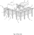
- the storage system 3 includes a plurality of robots 1 configured to move on dedicated supporting rails 13 and to receive a storage bin 2 from a storage column 8 within a bin storing grid 15.
- the prior art storage system 3 may also include a dedicated bin lift device 50, the latter being arranged to receive a storage bin 2 from the robot 1 at the top level of the storage system 3 and to convey the storage bin 2 down in a vertical direction to a delivery station, or port 60.
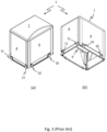
- FIG 3 (a) and (b) shows an example of a prior art robot 1 viewed from two different angles.
- the prior art robot 1 comprises a rectangular vehicle body or framework 4 displaying a cavity centrally arranged there within, a top cover 7 covering the top part of the body 4, and two sets of wheels 10,11 oriented perpendicular to each other.
- a vehicle lifting device 9 for lifting storage bins 2 are seen located within the cavity.
- the general configuration of the prior art robot 1 is to maximise the cavity size.
- Motors for the wheels 10,11 may for example be located adjacent to, or within, the respective wheels 10,11.
- the additional step of moving the robot 1 from one charging station 20 to another 20' is time consuming. Moreover, this additional step necessitates a built-in auxiliary power source that results in an undesired increase in the minimum robot size and/or decrease in the maximum robot cavity size into which storage bins 2 are situated. This is particularly important when using a compact designed robot such as the robot illustrated in figure 3 .
- a more general object is to provide a more efficient way of effectively charging a multiple number of batteries within a smallest possible area.
- the present invention provides a storage system comprising a base of rails arranged above a bin storing grid, a remotely operated vehicle and a charging station assembly, wherein the charging station assembly is for charging a plurality of power sources and comprises
- each power source comprises a connecting interface for interaction with the at least one connecting device.
- the connecting device is a connecting pin.
- the connecting device is at least two connecting pins.
- the at least one connecting pin may advantageously extend in a vertical direction and preferably the at least one connecting pin extend from the horizontally moveable support in an upwards vertical direction.
- the connecting interface comprises at least one cavity for accommodating the at least one connecting pin. In yet an embodiment, the connecting interface comprises a cavity for each of the at least two connecting pins.
- the power source transport device comprises
- the vertical directed drive shaft is drivingly connected to the power source lift via cooperating threads arranged on the drive shaft and the lift, such that the power source lift is moved in a direction dependent on the rotational direction of the vertical directed drive shaft.
- the power source transport device comprises
- the columns are preferably situated symmetrically around the drive shaft.
- the power source transport device comprises
- the power source lift comprises
- the plurality of charging stations is surrounded by a charging station framework/housing in which the power source lift may enter from below and move within.
- the charging station assembly comprises a control system for controlling charging of the power sources arranged in a charging position within the charging stations, the control system comprising
- the present invention provides a method for charging a plurality of power sources by a charging station assembly of a storage system, the storage system comprising a base of rails arranged above a bin storing grid and a remotely operated vehicle, and the charging station assembly comprises a charging station support fixing the charging station assembly on/at/to the base, the method comprising the following sequential steps:
- the method comprises the step of: e) retracting the power source connection means to the position of step b).
- the method comprises the step of: f) lifting the power source lift with the power source to a charging station configured to receive and charge the power source, the charging station being one of a plurality of charging stations.
- the method comprises the step of: g) horizontally positioning the power source connection means of the power source lift to a position in which the power source is connected in a charging position into the charging station.
- the vertical position in step b) is in line with, or immediately below, or immediately above, the vertical position of the power source.
- the method comprises the steps of:
- the charging station assembly is according to any embodiment of the first aspect.
- connection device' should be interpreted as any device, such as any suitable mechanical device, including pins, hooks or claws, and/or any suitable electromagnetic device, that may remove/replace the power source from/to its operational position in the remotely operated vehicle and/or its position in the charging station.
- FIGs. 1 and 2 give perspective views of prior art storage systems as described in further details above.
- Fig. 3 gives perspective views in two different angles of a robot 1 that may be used as part of the inventive charging station.
- This particular robot 1 comprises a rectangular vehicle body or framework 4 displaying a cavity 7 centrally arranged there within, a top lid 72 covering the top part of the body 4, a first set of four wheels 10 mounted inside the cavity 7 and a second set of four wheels 11 mounted at the exterior walls of the body 4.
- the first and second set of wheels 10,11 are oriented perpendicular to each other.
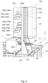
- Fig. 4 shows a part of a storage system 14,15 where the robot 1 is positioned near a multiple charging station 100 according to the invention.
- the multiple charging station 100 includes a transport device 101 for transporting a battery 106a-h from an operational position on or within the robot 1 to a charging position in one of a plurality of charging stations 106a'-h' located within a cuboid enclosure 108 which partly encloses the transport device 101.
- the enclosure 108 is open at least at its lower end for enabling a battery lift 102 of the transport device 101 to move freely between a lower position intended for removing a battery 106a from its operational position and an upper position intended for placing the battery 106a into its the charging position within any available/void charging station 106a'.
- Cartesian coordinate system is shown with its X, Y and Z axes aligned along the principal directions of the storage system 14,15. Any direction within the X,Y plane is referred to as a horizontal direction and any direction along the z-direction is referred to as a vertical direction.
- the battery lift 102 may be moved in a vertical direction (z-direction) via a drive shaft 104 connected to a remotely operated motor 109.
- the transport device 101 also includes two vertical support columns 103 situated symmetrically on each side of the battery lift 102 along the y-direction.
- the support columns 103 has guiding tracks 103a, into which protrusions 102d extending on both sides of the battery lift 102 towards the columns 103 are inserted in order enable stable vertical movements.
- Each protrusion 102d is preferably shaped as a mushroom, where the horizontal widths of the mushroom head and the mushroom trunk in the x-direction are larger and smaller, respectively, than the corresponding horizontal width of the guiding tracks 103a.
- Fig. 5 shows in further details the mechanism 102a,b for inserting / removing the battery 106a-h to/from the operation position on the robot 1, the mechanism 102a,c for horizontal movements towards/from the operational position and the mechanism 102d,103a for guiding the battery lift 102 in the vertical direction along the support columns.
- the particular embodiment utilizes connecting pins 102b fixed at one end to a support plate 102a.
- the pins 102b are vertically guided into corresponding cavities (not shown) situated at the lower face of the battery 106a by raising the battery lift 102 until the battery 106a is abutting, or near abutting, the support plate 102a.
- the support plate 102a may be horizontally adjusted on a vertically movable frame 102c.
- the horizontal movement may for example be achieved using the same principles as for the vertical movement, i.e. using a drive shaft in the x-direction rotationally connected to the motor 109.
- any drive mechanism known in the art capable of moving the support plate, or the entire battery lift 102, horizontally may be envisaged.
- any means for connecting / disconnecting a battery 106a from a robot 1 may be envisaged, involving mechanical means, magnetic means or a combination of both.
- the battery comprises electric connectors for connecting to cooperating connectors on the robot 1 and preferably on the charging station.
- Various types of connectors are obvious to the skilled person based on the present disclosure and include for instance stab/receptacle type connectors (i.e. male/female connectors) and slide/blade connectors.
- the movement between the lower and the upper positions involves horizontal and vertical movements separated in time.
- alternative movement paths of the batteries 106a-h are feasible.
- the batteries 106a-h are mounted on the top surface of the robot 1 one may envisage purely vertical movements during placement / disconnection of batteries 106a-h from the robot 1.
- the battery lift 102 is lowered vertically, then grabs the battery 106a using for example hooks or claws, and finally raised, all operation performed by vertical movements.
- Movement paths involving simultaneous horizontal and vertical movements are also possible.
- the horizontal movements of the support plate 102a may start before the battery lift 102 has reached its final positions, thereby reducing operational time.
- All operations of both the robots 1 and the multiple charging stations 100 may be controlled by wireless communication means and remote control units.
- multiple charging stations 100 may be equipped with a control system allowing control of the charging process by monitoring the state of charge of each battery 106a-h during charging and wirelessly communicating the state of charge real-time to the operator and/or to a receiver in the transport device 101.
- the motor 109 may be programmed accordingly.
- the communication of the state of charge to the transport device 101 may be achieved directly or via another system.
Landscapes
- Engineering & Computer Science (AREA)
- Mechanical Engineering (AREA)
- Power Engineering (AREA)
- Transportation (AREA)
- Charge And Discharge Circuits For Batteries Or The Like (AREA)
- Electric Propulsion And Braking For Vehicles (AREA)
- Warehouses Or Storage Devices (AREA)
- Vehicle Cleaning, Maintenance, Repair, Refitting, And Outriggers (AREA)
Claims (14)
- Speichersystem, umfassend ein Behalterlagernetz (15), eine Basis (14) von Schienen (13), die caber dem Behalterlagernetz angeordnet ist, ein ferngesteuertes Fahrzeug (1) und eine Ladestationsbaugruppe (100), wobei die Ladestationsbaugruppe zum Laden einer Vielzahl von Stromquellen (106a-g) dient und Folgendes umfasst:eine Ladestationshalterung (107), welche die Ladestationsbaugruppe (100) an der Basis (14) befestigt;gekennzeichnet durch ferner umfassend:eine Vielzahl von Ladestationen (106a'-h'), wobei jede Ladestation (106a'-h') in einer unterschiedlichen vertikalen Position angeordnet ist und Lademittel zum Laden von einer der Vielzahl von Stromquellen (106a-h) umfasst; undeine Stromquellentransportvorrichtung (101), die eine Verlagerung einer beliebigen der Stromquellen (106a-h) zwischen einer Betriebsposition an dem ferngesteuerten Fahrzeug (1) und einer Ladeposition in oder an einer der Vielzahl von Ladestationen (106a'-h') ermoglicht; wobei
die Stromquellentransportvorrichtung (101) einen Stromquellenaufzug (102) umfasst, der vertikal zwischen Folgenden bewegt werden kann:einer ersten vertikalen Position parallel zu oder beinahe parallel zu einer Stromquellenposition an dem ferngesteuerten Fahrzeug (1), wenn sick das ferngesteuerte Fahrzeug an der Basis (14) befindet, undeiner zweiten vertikalen Position parallel zu oder beinahe parallel zu einer beliebigen der Vielzahl von Ladestationen (106a'-h'),wobei die erste vertikale Position auf einer niedrigeren Ebene liegt als die zweite vertikale Position, undder Stromquellenaufzug (102) Stromquellenverbindungsmittel (102a, 102b) umfasst, dieeine horizontal bewegliche Halterung (102a) umfassen, undzumindest eine Verbindungsvorrichtung (102b) zum umkehrbaren Trennen der Stromquelle (106b-h) von ihrer Betriebsposition an dem ferngesteuerten Fahrzeug (1) wahrend des Gebrauchs an der horizontal beweglichen Halterung (102a) befestigt ist; undwobei die zweite vertikale Position auf einer Ebene caber einer obersten Ebene des ferngesteuerten Fahrzeugs (1) liegt, sodass das ferngesteuerte Fahrzeug wahrend des umkehrbaren Trennens von einer der Vielzahl von Stromquellen (106a-h) von ihrer Betriebsposition an dem ferngesteuerten Fahrzeug (1) wahrend des Gebrauchs unter der Vielzahl von Ladestationen (106a'-h') positioniert ist. - Speichersystem nach Anspruch 1, wobei die Vielzahl von Ladestationen (106a'-h') durch einen Ladestationsrahmen (108) umgeben ist, in den der Stromquellenaufzug (102) von unten eintreten und in dem sick dieser bewegen kann.
- Speichersystem nach Anspruch 1 oder 2, wobei eine untere Ebene des Ladestationsrahmens (108) hoher als eine oberste Ebene des ferngesteuerten Fahrzeugs (1) ist, sodass das ferngesteuerte Fahrzeug unter dem Ladestationsrahmen und der Vielzahl von Ladestationen (106a'-h') positioniert werden kann.
- Speichersystem nach einem der Anspr-Uche 1-3, wobei eine unterste Ebene des Ladestationsrahmens (108) hoher als eine oberste Ebene des ferngesteuerten Fahrzeugs (1) ist.
- Speichersystem nach Anspruch 1, wobei die Stromquellentransportvorrichtung (101) einen ferngesteuerten Motor (109) und zumindest eine vertikal ausgerichtete Saule (103) umfasst, die an einem Langsende an der Ladestationshalterung (107) befestigt ist und sick zumindest zu den obersten Ladestationen (106h') erstreckt, und der Stromquellenaufzug (102) mithilfe des ferngesteuerten Motors (109) vertikal entlang der Saule (103) bewegt werden kann.
- Speichersystem nach einem der vorangehenden Ansprtiche, wobei der Stromquellenaufzug (102) Folgendes umfasst:einen vertikal beweglichen Rahmen (102c); undwobei die Stromquellenverbindungsmittel (102a, 102b) horizontal an dem vertikal beweglichen Rahmen (102c) bewegt werden konnen.
- Speichersystem nach einem der vorangehenden Ansprtiche, wobei jede Stromquelle eine Verbindungsschnittstelle zur Interaktion mit der zumindest einer Verbindungsvorrichtung (102b) umfasst.
- Speichersystem nach einem der vorangehenden Ansprtiche, wobei die Verbindungsvorrichtung ein Verbindungsstift (102b) ist.
- Speichersystem nach Anspruch 8, wobei die Verbindungsschnittstelle zumindest ein Hohlraum zum Aufnehmen des zumindest einen Verbindungsstiftes (102b) ist.
- Speichersystem nach Anspruch 3, wobei die Stromquellentransportvorrichtung (101) Folgendes umfasst:
eine vertikal ausgerichtete Antriebswelle (104), die antriebsmaBig mit dem Stromquellenaufzug (102) verbunden ist; und- wobei der ferngesteuerte Motor (109) dazu dient, die Antriebswelle (104) anzutreiben. - Speichersystem nach Anspruch 5, wobei der Stromquellenaufzug (102) Folgendes umfasst:zumindest einen sich horizontal erstreckenden Vorsprung; undwobei die zumindest eine Saule (103) zumindest eine Aussparung (103a) aufweist, die einen Vorsprung aufnimmt und sich entlang der zumindest einen Saule (103) erstreckt;wobei der Stromquellenaufzug (102) und die zumindest eine Saule (103) derart ausgebildet sind, dass der zumindest eine Vorsprung wahrend einer vertikalen Bewegung des Stromquellenaufzugs (102) in der zumindest einen Aussparung (103a) gleitet.
- Speichersystem nach einem der vorangehenden Ansprtiche, wobei die Ladestationsbaugruppe (100) ein Steuersystem zum Steuern eines Ladens der Stromquellen (106a-h) umfasst, die in einer Ladeposition in den Ladestationen (106a'-h') angeordnet sind, wobei das Steuersystem Folgendes umfasst:- Uberwachungsmittel zum Uberwachen eines Ladezustandes der Stromquellen (106a-h); und Signalkommunikationsmittel zum Kommunizieren des Ladezustandes der Stromquellen (106a-h) an zumindest einen Empfanger an der Stromquellentransportvorrichtung (101) oder einen Remote-Bediener oder eine Kombination davon.
- Verfahren zum Austauschen der Stromquelle eines ferngesteuerten Fahrzeugs (1) in einem Speichersystem nach einem der vorangehenden Anspr-Uche, umfassend die folgenden Schritte:a. Fahren des ferngesteuerten Fahrzeugs (1) in eine vorbestimmte Position unter der Vielzahl von Ladestationen (106a'-h');b. Absenken des Stromquellenaufzugs (102) in die erste Position;c. horizontales Positionieren der Stromquellenverbindungsmittel (102a, 102b) in eine Position, in der die Stromquelle von dem ferngesteuerten Fahrzeug getrennt werden kann;d. Trennen der Stromquelle von dem ferngesteuerten Fahrzeug; ande. Anheben des Stromquellenaufzugs (102) in die zweite Position.
- Verfahren nach Anspruch 13, umfassend den folgenden Schritt:
f. horizontales Positionieren der Stromquellenverbindungsmittel in eine Position, in der die Stromquelle in einer Ladeposition in einer Ladestation angeschlossen ist.
Priority Applications (1)
| Application Number | Priority Date | Filing Date | Title |
|---|---|---|---|
| PL17731877.1T PL3471994T5 (pl) | 2016-06-21 | 2017-06-21 | Stacja ładowania z wieloma źródłami zasilania |
Applications Claiming Priority (2)
| Application Number | Priority Date | Filing Date | Title |
|---|---|---|---|
| NO20161039A NO344308B1 (en) | 2016-06-21 | 2016-06-21 | Storage system comprising a charging station assembly and method of replacing the power source of a remotely operated vehicle |
| PCT/EP2017/065165 WO2017220627A1 (en) | 2016-06-21 | 2017-06-21 | Charging station with multiple power sources |
Publications (3)
| Publication Number | Publication Date |
|---|---|
| EP3471994A1 EP3471994A1 (de) | 2019-04-24 |
| EP3471994B1 EP3471994B1 (de) | 2021-10-20 |
| EP3471994B2 true EP3471994B2 (de) | 2025-01-08 |
Family
ID=59093558
Family Applications (1)
| Application Number | Title | Priority Date | Filing Date |
|---|---|---|---|
| EP17731877.1A Active EP3471994B2 (de) | 2016-06-21 | 2017-06-21 | Ladestation mit mehreren stromquellen |
Country Status (11)
| Country | Link |
|---|---|
| US (1) | US10819126B2 (de) |
| EP (1) | EP3471994B2 (de) |
| JP (1) | JP7068202B2 (de) |
| CN (1) | CN109328150B (de) |
| CA (1) | CA3027621A1 (de) |
| DK (1) | DK3471994T4 (de) |
| ES (1) | ES2901056T5 (de) |
| NO (1) | NO344308B1 (de) |
| PL (1) | PL3471994T5 (de) |
| TW (1) | TW201811585A (de) |
| WO (1) | WO2017220627A1 (de) |
Families Citing this family (42)
| Publication number | Priority date | Publication date | Assignee | Title |
|---|---|---|---|---|
| GB201314313D0 (en) * | 2013-08-09 | 2013-09-25 | Ocado Ltd | Apparatus for retrieving units from a storage system |
| US11858738B2 (en) | 2013-08-09 | 2024-01-02 | Ocado Innovation Limited | Apparatus for retrieving units from a storage system |
| USD897623S1 (en) * | 2017-02-17 | 2020-09-29 | Autostore Technology AS | Dual track |
| JP6286084B1 (ja) * | 2017-03-24 | 2018-02-28 | 本田技研工業株式会社 | 収容装置 |
| NO346327B1 (en) | 2017-05-16 | 2022-06-07 | Autostore Tech As | Automated storage and retrieval system |
| US11360465B2 (en) | 2017-05-16 | 2022-06-14 | Autostore Technology AS | Automated storage and retrieval system |
| NO20180586A1 (en) | 2018-04-25 | 2019-10-28 | Autostore Tech As | Charging system for container handling vehicles and method of charging a power supply |
| EP3737622B1 (de) | 2018-01-09 | 2025-10-15 | Autostore Technology AS | Verschiebungsmechanismus für ein ferngesteuertes fahrzeug |
| NO346364B1 (en) * | 2018-04-25 | 2022-06-27 | Autostore Tech As | Container handling vehicle with first and second sections and battery in second section, and system. |
| NO346347B1 (en) | 2018-04-25 | 2022-06-20 | Autostore Tech As | Container handling vehicle comprising first and second section and assembly of motors in second section, and system |
| EP4480861A3 (de) | 2018-04-25 | 2025-03-12 | AutoStore Technology AS | Containerhandhabungsfahrzeug mit einem ersten und einem zweiten abschnitt und einer anordnung von motoren in einem zweiten abschnitt zum antreiben mindestens eines rades eines jeden radsatzes |
| GB201807562D0 (en) * | 2018-05-09 | 2018-06-20 | Ocado Innovation Ltd | Apparatus and method for charging a robotic load handling device |
| NO344889B1 (en) * | 2018-06-06 | 2020-06-15 | Autostore Tech As | A service vehicle, an automated storage and retrieval system using such a service vehicle and a method thereof |
| CA3099247A1 (en) * | 2018-06-12 | 2019-12-19 | Autostore Technology AS | Automated storage system with a container vehicle and a charging system |
| WO2019238702A1 (en) * | 2018-06-12 | 2019-12-19 | Autostore Technology AS | Automated storage system with a container vehicle and a charging system |
| NO346644B1 (en) * | 2019-02-19 | 2022-11-14 | Autostore Tech As | A storage system, a container vehicle and a charging station for the storage system and a method of charging the container vehicle. |
| CA3098974A1 (en) | 2018-06-12 | 2019-12-19 | Autostore Technology AS | A delivery system with an access point and a method of accessing an access point of the delivery system |
| CN112272643B (zh) | 2018-06-12 | 2022-08-09 | 自动存储科技股份有限公司 | 具有升降装置的容器存取站 |
| NO344742B1 (en) | 2018-06-12 | 2020-03-30 | Autostore Tech As | A delivery system with an access point and a method of accessing an access point of the delivery system |
| CN109249821B (zh) * | 2018-09-12 | 2021-09-17 | 郑州信息科技职业学院 | 一种可调节充电位置的新能源汽车充电装置 |
| NO345766B1 (en) * | 2018-10-12 | 2021-07-19 | Autostore Tech As | A mobile storage system and a method of providing the mobile storage system |
| WO2020125774A1 (zh) * | 2018-12-21 | 2020-06-25 | 苏州宝时得电动工具有限公司 | 一种机器人清洁系统、基站及控制方法 |
| NO20190219A1 (en) * | 2019-02-18 | 2020-08-19 | Autostore Tech As | System and a method for harvesting energy from a container handling vehicle. |
| WO2020169287A1 (en) * | 2019-02-19 | 2020-08-27 | Autostore Technology AS | Storage system |
| NO346042B1 (en) * | 2019-03-29 | 2022-01-17 | Autostore Tech As | Dynamic Power Management |
| NO347473B1 (en) | 2019-04-12 | 2023-11-13 | Autostore Tech As | Li-Fi for data communication in Autostore |
| NO346306B1 (en) | 2019-08-22 | 2022-05-30 | Autostore Tech As | A delivery system, an automated storage and retrieval system and a method of transporting a container |
| NO345918B1 (en) | 2019-09-16 | 2021-10-18 | Autostore Tech As | Automated storage and retrieval system using an automated loader and methods of replacing power supplies |
| NO345589B1 (en) * | 2019-09-26 | 2021-05-03 | Autostore Tech As | System and method for power management |
| CN111217076B (zh) * | 2020-01-09 | 2021-12-17 | 上海航天电子通讯设备研究所 | 一种应急助航灯具存储装置 |
| DE102020203221A1 (de) | 2020-03-12 | 2021-09-16 | Gebhardt Fördertechnik GmbH | Fahrzeug für ein Lagersystem sowie Ladestation für das Fahrzeug |
| NO345963B1 (en) * | 2020-03-31 | 2021-11-15 | Autostore Tech As | Intelligent maintenance system |
| US11607711B2 (en) | 2020-03-31 | 2023-03-21 | United Parcel Service Of America, Inc. | Multi-tiered parcel sortation system |
| NO346054B1 (en) * | 2020-06-08 | 2022-01-24 | Autostore Tech As | System and method of determining status of a charging station |
| WO2023017183A1 (en) * | 2021-08-13 | 2023-02-16 | Ocado Innovation Limited | Load handling device & methods of exchanging a power source |
| GB202111638D0 (en) * | 2021-08-13 | 2021-09-29 | Ocado Innovation Ltd | Load handling device, storage and retrieval system & method |
| CN115912528A (zh) * | 2021-09-30 | 2023-04-04 | 宁德时代新能源科技股份有限公司 | 换电设备及换电系统 |
| CA3243285A1 (en) | 2022-01-31 | 2023-08-03 | Dematic Corp. | Temperature-controlled container with lid for automated storage and retrieval system |
| GB202300771D0 (en) | 2022-01-31 | 2023-03-08 | Dematic Corp | Automated storage and retrieval system and microclimate-controlled receptacles for pharmaceuticals and method for operating same |
| GB2616945B (en) | 2022-01-31 | 2025-03-26 | Dematic Corp | Automated storage and retrieval system with microclimate-controlled receptacles |
| GB2619064A (en) * | 2022-05-26 | 2023-11-29 | Ocado Innovation Ltd | A combined power and data unit for a storage and retreival system, and related devices |
| CN119744245A (zh) * | 2022-07-04 | 2025-04-01 | 奥卡多创新有限公司 | 用于从存储和取回系统取回存储容器的装置 |
Citations (5)
| Publication number | Priority date | Publication date | Assignee | Title |
|---|---|---|---|---|
| JPH03183302A (ja) † | 1989-12-08 | 1991-08-09 | Ishikawajima Harima Heavy Ind Co Ltd | 無人台車のバッテリ交換方法 |
| CN102602372A (zh) † | 2012-03-20 | 2012-07-25 | 山东鲁能智能技术有限公司 | 一种电动公交车电池快换系统及其换电方法 |
| US20130343842A1 (en) † | 2012-06-26 | 2013-12-26 | Motex Products Co., Ltd. | System for auto-exchanging of electric vehicle battery |
| US20140002019A1 (en) † | 2012-07-01 | 2014-01-02 | Kookmin University Industry Academy Cooperation Foundation | Battery exchanging-type charging station system for electric vehicle |
| CN104842964A (zh) † | 2015-06-05 | 2015-08-19 | 上海振华重工(集团)股份有限公司 | 电动车辆的电池更换设备 |
Family Cites Families (15)
| Publication number | Priority date | Publication date | Assignee | Title |
|---|---|---|---|---|
| KR910006494B1 (ko) * | 1988-07-13 | 1991-08-27 | 삼성전자 주식회사 | 무인반송차의 배터리 자동교환 장치 |
| US5187423A (en) | 1991-05-15 | 1993-02-16 | Marton Louis L | System for replenishment of energy stored in a battery on an electric vehicle |
| JP2932221B2 (ja) * | 1991-05-29 | 1999-08-09 | 日本輸送機株式会社 | 連結装置 |
| US5545967A (en) * | 1995-07-21 | 1996-08-13 | Precision Automation Systems, Inc. | Automatic battery management system |
| JPH11150809A (ja) * | 1997-09-15 | 1999-06-02 | Honda Motor Co Ltd | バッテリ・レンタルシステム |
| JP2000302206A (ja) * | 1999-04-16 | 2000-10-31 | Mitsubishi Heavy Ind Ltd | 搬送台車のバッテリ管理設備 |
| NO317366B1 (no) | 1999-07-01 | 2004-10-18 | Autostore As | Lagringsanlegg med fjernstyrte vogner med to hjulsett og heisinnretning for drift på skinner anlagt i kryss over kolonner av lagringsenheter som er adskilt med vertikale profilstolper |
| US8006793B2 (en) * | 2008-09-19 | 2011-08-30 | Better Place GmbH | Electric vehicle battery system |
| DE102009025052A1 (de) * | 2009-06-10 | 2011-04-28 | Gottwald Port Technology Gmbh | System zum Wechseln einer Batterie eines flurgebundenen Tranportfahrzeuges, insbesondere eines fahrerlosen Schwerlast-Transportfahrzeuges für ISO-Container |
| DE102009045340A1 (de) * | 2009-09-18 | 2011-03-24 | Jungheinrich Aktiengesellschaft | Batterieentnahmegerät für ein Fahrzeug, insbesondere Elektroflurförderzeug, und Verriegelungseinrichtung für ein solches Batterieentnahmegerät |
| US20110106294A1 (en) * | 2009-10-30 | 2011-05-05 | John Bean Technologies Corporation | Automatic battery exchange system for mobile vehicles |
| FR2978717B1 (fr) * | 2011-08-02 | 2014-02-14 | Renault Sa | Structure de stockage de batteries de vehicule automobile avec mecanisme de verrouillage des batteries dans les cellules de stockage |
| WO2013039569A1 (en) * | 2011-09-12 | 2013-03-21 | Carestream Health, Inc. | Charger for electronic grid holders and detectors stored at mobile radiographic imaging apparatus and methods for using the same |
| FR2982224B1 (fr) * | 2011-11-07 | 2014-05-09 | Renault Sas | Station semi-automatique d'echange de batterie de traction pour vehicule electrique ou hybride |
| NO340313B1 (no) | 2014-01-08 | 2017-03-27 | Jakob Hatteland Logistics As | Fjernstyrt kjøretøy for å plukke opp lagringsbeholdere fra et lagringssystem, lagringssystem for lagring av beholdere og fremgangsmåte for å bytte en strømkilde |
-
2016
- 2016-06-21 NO NO20161039A patent/NO344308B1/en unknown
-
2017
- 2017-06-21 JP JP2018566556A patent/JP7068202B2/ja active Active
- 2017-06-21 CN CN201780038186.1A patent/CN109328150B/zh active Active
- 2017-06-21 DK DK17731877.1T patent/DK3471994T4/da active
- 2017-06-21 US US16/312,347 patent/US10819126B2/en active Active
- 2017-06-21 EP EP17731877.1A patent/EP3471994B2/de active Active
- 2017-06-21 WO PCT/EP2017/065165 patent/WO2017220627A1/en not_active Ceased
- 2017-06-21 TW TW106120686A patent/TW201811585A/zh unknown
- 2017-06-21 ES ES17731877T patent/ES2901056T5/es active Active
- 2017-06-21 PL PL17731877.1T patent/PL3471994T5/pl unknown
- 2017-06-21 CA CA3027621A patent/CA3027621A1/en active Pending
Patent Citations (5)
| Publication number | Priority date | Publication date | Assignee | Title |
|---|---|---|---|---|
| JPH03183302A (ja) † | 1989-12-08 | 1991-08-09 | Ishikawajima Harima Heavy Ind Co Ltd | 無人台車のバッテリ交換方法 |
| CN102602372A (zh) † | 2012-03-20 | 2012-07-25 | 山东鲁能智能技术有限公司 | 一种电动公交车电池快换系统及其换电方法 |
| US20130343842A1 (en) † | 2012-06-26 | 2013-12-26 | Motex Products Co., Ltd. | System for auto-exchanging of electric vehicle battery |
| US20140002019A1 (en) † | 2012-07-01 | 2014-01-02 | Kookmin University Industry Academy Cooperation Foundation | Battery exchanging-type charging station system for electric vehicle |
| CN104842964A (zh) † | 2015-06-05 | 2015-08-19 | 上海振华重工(集团)股份有限公司 | 电动车辆的电池更换设备 |
Also Published As
| Publication number | Publication date |
|---|---|
| EP3471994B1 (de) | 2021-10-20 |
| EP3471994A1 (de) | 2019-04-24 |
| US20190232925A1 (en) | 2019-08-01 |
| DK3471994T3 (da) | 2021-12-20 |
| CN109328150A (zh) | 2019-02-12 |
| JP2019527527A (ja) | 2019-09-26 |
| DK3471994T4 (da) | 2025-02-03 |
| WO2017220627A1 (en) | 2017-12-28 |
| ES2901056T3 (es) | 2022-03-21 |
| PL3471994T5 (pl) | 2025-03-17 |
| ES2901056T5 (en) | 2025-03-11 |
| US10819126B2 (en) | 2020-10-27 |
| JP7068202B2 (ja) | 2022-05-16 |
| TW201811585A (zh) | 2018-04-01 |
| CN109328150B (zh) | 2022-08-19 |
| NO344308B1 (en) | 2019-10-28 |
| CA3027621A1 (en) | 2017-12-28 |
| PL3471994T3 (pl) | 2022-02-14 |
| NO20161039A1 (en) | 2017-12-22 |
Similar Documents
| Publication | Publication Date | Title |
|---|---|---|
| EP3471994B2 (de) | Ladestation mit mehreren stromquellen | |
| JP7307120B2 (ja) | 保管容器を搬送するためのロボット | |
| EP3707026B1 (de) | Mehrfachladestation für ein speichersystem und verfahren dafür | |
| AU2022327771B2 (en) | Load handling device, storage and retrieval system & method | |
| WO2023017183A1 (en) | Load handling device & methods of exchanging a power source | |
| KR20160106098A (ko) | 저장 상자 이송용 로봇 | |
| HK1260736A1 (en) | Charging station with multiple power sources | |
| HK1260736B (en) | Charging station with multiple power sources | |
| WO2025003365A2 (en) | Charging station | |
| GB2627200A (en) | Methods of exchanging a rechargeable battery and a battery exchange station |
Legal Events
| Date | Code | Title | Description |
|---|---|---|---|
| STAA | Information on the status of an ep patent application or granted ep patent |
Free format text: STATUS: UNKNOWN |
|
| STAA | Information on the status of an ep patent application or granted ep patent |
Free format text: STATUS: THE INTERNATIONAL PUBLICATION HAS BEEN MADE |
|
| PUAI | Public reference made under article 153(3) epc to a published international application that has entered the european phase |
Free format text: ORIGINAL CODE: 0009012 |
|
| STAA | Information on the status of an ep patent application or granted ep patent |
Free format text: STATUS: REQUEST FOR EXAMINATION WAS MADE |
|
| 17P | Request for examination filed |
Effective date: 20190104 |
|
| AK | Designated contracting states |
Kind code of ref document: A1 Designated state(s): AL AT BE BG CH CY CZ DE DK EE ES FI FR GB GR HR HU IE IS IT LI LT LU LV MC MK MT NL NO PL PT RO RS SE SI SK SM TR |
|
| AX | Request for extension of the european patent |
Extension state: BA ME |
|
| DAV | Request for validation of the european patent (deleted) | ||
| DAX | Request for extension of the european patent (deleted) | ||
| STAA | Information on the status of an ep patent application or granted ep patent |
Free format text: STATUS: EXAMINATION IS IN PROGRESS |
|
| 17Q | First examination report despatched |
Effective date: 20200408 |
|
| REG | Reference to a national code |
Ref country code: DE Ref legal event code: R079 Ref document number: 602017047884 Country of ref document: DE Free format text: PREVIOUS MAIN CLASS: B60L0011180000 Ipc: B60L0053300000 |
|
| GRAP | Despatch of communication of intention to grant a patent |
Free format text: ORIGINAL CODE: EPIDOSNIGR1 |
|
| STAA | Information on the status of an ep patent application or granted ep patent |
Free format text: STATUS: GRANT OF PATENT IS INTENDED |
|
| RIC1 | Information provided on ipc code assigned before grant |
Ipc: H02J 7/00 20060101ALI20210511BHEP Ipc: B66F 9/07 20060101ALI20210511BHEP Ipc: B60S 5/06 20190101ALI20210511BHEP Ipc: B60L 53/80 20190101ALI20210511BHEP Ipc: B60L 53/30 20190101AFI20210511BHEP |
|
| INTG | Intention to grant announced |
Effective date: 20210602 |
|
| GRAS | Grant fee paid |
Free format text: ORIGINAL CODE: EPIDOSNIGR3 |
|
| GRAA | (expected) grant |
Free format text: ORIGINAL CODE: 0009210 |
|
| STAA | Information on the status of an ep patent application or granted ep patent |
Free format text: STATUS: THE PATENT HAS BEEN GRANTED |
|
| AK | Designated contracting states |
Kind code of ref document: B1 Designated state(s): AL AT BE BG CH CY CZ DE DK EE ES FI FR GB GR HR HU IE IS IT LI LT LU LV MC MK MT NL NO PL PT RO RS SE SI SK SM TR |
|
| REG | Reference to a national code |
Ref country code: GB Ref legal event code: FG4D |
|
| REG | Reference to a national code |
Ref country code: CH Ref legal event code: EP |
|
| REG | Reference to a national code |
Ref country code: DE Ref legal event code: R096 Ref document number: 602017047884 Country of ref document: DE |
|
| REG | Reference to a national code |
Ref country code: IE Ref legal event code: FG4D |
|
| REG | Reference to a national code |
Ref country code: AT Ref legal event code: REF Ref document number: 1439666 Country of ref document: AT Kind code of ref document: T Effective date: 20211115 |
|
| REG | Reference to a national code |
Ref country code: DK Ref legal event code: T3 Effective date: 20211217 |
|
| REG | Reference to a national code |
Ref country code: SE Ref legal event code: TRGR |
|
| REG | Reference to a national code |
Ref country code: NL Ref legal event code: FP |
|
| REG | Reference to a national code |
Ref country code: LT Ref legal event code: MG9D |
|
| REG | Reference to a national code |
Ref country code: AT Ref legal event code: MK05 Ref document number: 1439666 Country of ref document: AT Kind code of ref document: T Effective date: 20211020 |
|
| REG | Reference to a national code |
Ref country code: ES Ref legal event code: FG2A Ref document number: 2901056 Country of ref document: ES Kind code of ref document: T3 Effective date: 20220321 |
|
| PG25 | Lapsed in a contracting state [announced via postgrant information from national office to epo] |
Ref country code: RS Free format text: LAPSE BECAUSE OF FAILURE TO SUBMIT A TRANSLATION OF THE DESCRIPTION OR TO PAY THE FEE WITHIN THE PRESCRIBED TIME-LIMIT Effective date: 20211020 Ref country code: LT Free format text: LAPSE BECAUSE OF FAILURE TO SUBMIT A TRANSLATION OF THE DESCRIPTION OR TO PAY THE FEE WITHIN THE PRESCRIBED TIME-LIMIT Effective date: 20211020 Ref country code: FI Free format text: LAPSE BECAUSE OF FAILURE TO SUBMIT A TRANSLATION OF THE DESCRIPTION OR TO PAY THE FEE WITHIN THE PRESCRIBED TIME-LIMIT Effective date: 20211020 Ref country code: BG Free format text: LAPSE BECAUSE OF FAILURE TO SUBMIT A TRANSLATION OF THE DESCRIPTION OR TO PAY THE FEE WITHIN THE PRESCRIBED TIME-LIMIT Effective date: 20220120 Ref country code: AT Free format text: LAPSE BECAUSE OF FAILURE TO SUBMIT A TRANSLATION OF THE DESCRIPTION OR TO PAY THE FEE WITHIN THE PRESCRIBED TIME-LIMIT Effective date: 20211020 |
|
| PG25 | Lapsed in a contracting state [announced via postgrant information from national office to epo] |
Ref country code: IS Free format text: LAPSE BECAUSE OF FAILURE TO SUBMIT A TRANSLATION OF THE DESCRIPTION OR TO PAY THE FEE WITHIN THE PRESCRIBED TIME-LIMIT Effective date: 20220220 Ref country code: PT Free format text: LAPSE BECAUSE OF FAILURE TO SUBMIT A TRANSLATION OF THE DESCRIPTION OR TO PAY THE FEE WITHIN THE PRESCRIBED TIME-LIMIT Effective date: 20220221 Ref country code: NO Free format text: LAPSE BECAUSE OF FAILURE TO SUBMIT A TRANSLATION OF THE DESCRIPTION OR TO PAY THE FEE WITHIN THE PRESCRIBED TIME-LIMIT Effective date: 20220120 Ref country code: LV Free format text: LAPSE BECAUSE OF FAILURE TO SUBMIT A TRANSLATION OF THE DESCRIPTION OR TO PAY THE FEE WITHIN THE PRESCRIBED TIME-LIMIT Effective date: 20211020 Ref country code: HR Free format text: LAPSE BECAUSE OF FAILURE TO SUBMIT A TRANSLATION OF THE DESCRIPTION OR TO PAY THE FEE WITHIN THE PRESCRIBED TIME-LIMIT Effective date: 20211020 Ref country code: GR Free format text: LAPSE BECAUSE OF FAILURE TO SUBMIT A TRANSLATION OF THE DESCRIPTION OR TO PAY THE FEE WITHIN THE PRESCRIBED TIME-LIMIT Effective date: 20220121 |
|
| REG | Reference to a national code |
Ref country code: DE Ref legal event code: R026 Ref document number: 602017047884 Country of ref document: DE |
|
| PLBI | Opposition filed |
Free format text: ORIGINAL CODE: 0009260 |
|
| PG25 | Lapsed in a contracting state [announced via postgrant information from national office to epo] |
Ref country code: SM Free format text: LAPSE BECAUSE OF FAILURE TO SUBMIT A TRANSLATION OF THE DESCRIPTION OR TO PAY THE FEE WITHIN THE PRESCRIBED TIME-LIMIT Effective date: 20211020 Ref country code: SK Free format text: LAPSE BECAUSE OF FAILURE TO SUBMIT A TRANSLATION OF THE DESCRIPTION OR TO PAY THE FEE WITHIN THE PRESCRIBED TIME-LIMIT Effective date: 20211020 Ref country code: RO Free format text: LAPSE BECAUSE OF FAILURE TO SUBMIT A TRANSLATION OF THE DESCRIPTION OR TO PAY THE FEE WITHIN THE PRESCRIBED TIME-LIMIT Effective date: 20211020 Ref country code: EE Free format text: LAPSE BECAUSE OF FAILURE TO SUBMIT A TRANSLATION OF THE DESCRIPTION OR TO PAY THE FEE WITHIN THE PRESCRIBED TIME-LIMIT Effective date: 20211020 |
|
| PLAB | Opposition data, opponent's data or that of the opponent's representative modified |
Free format text: ORIGINAL CODE: 0009299OPPO |
|
| PLAX | Notice of opposition and request to file observation + time limit sent |
Free format text: ORIGINAL CODE: EPIDOSNOBS2 |
|
| 26 | Opposition filed |
Opponent name: ABITZ & PARTNER PATENTANWAELTE MBB Effective date: 20220720 |
|
| R26 | Opposition filed (corrected) |
Opponent name: ABITZ & PARTNER PATENTANWAELTE MBB Effective date: 20220720 |
|
| PG25 | Lapsed in a contracting state [announced via postgrant information from national office to epo] |
Ref country code: AL Free format text: LAPSE BECAUSE OF FAILURE TO SUBMIT A TRANSLATION OF THE DESCRIPTION OR TO PAY THE FEE WITHIN THE PRESCRIBED TIME-LIMIT Effective date: 20211020 |
|
| PG25 | Lapsed in a contracting state [announced via postgrant information from national office to epo] |
Ref country code: SI Free format text: LAPSE BECAUSE OF FAILURE TO SUBMIT A TRANSLATION OF THE DESCRIPTION OR TO PAY THE FEE WITHIN THE PRESCRIBED TIME-LIMIT Effective date: 20211020 |
|
| PLBB | Reply of patent proprietor to notice(s) of opposition received |
Free format text: ORIGINAL CODE: EPIDOSNOBS3 |
|
| PG25 | Lapsed in a contracting state [announced via postgrant information from national office to epo] |
Ref country code: MC Free format text: LAPSE BECAUSE OF FAILURE TO SUBMIT A TRANSLATION OF THE DESCRIPTION OR TO PAY THE FEE WITHIN THE PRESCRIBED TIME-LIMIT Effective date: 20211020 |
|
| PG25 | Lapsed in a contracting state [announced via postgrant information from national office to epo] |
Ref country code: LU Free format text: LAPSE BECAUSE OF NON-PAYMENT OF DUE FEES Effective date: 20220621 Ref country code: IE Free format text: LAPSE BECAUSE OF NON-PAYMENT OF DUE FEES Effective date: 20220621 |
|
| P01 | Opt-out of the competence of the unified patent court (upc) registered |
Effective date: 20230524 |
|
| PLBP | Opposition withdrawn |
Free format text: ORIGINAL CODE: 0009264 |
|
| REG | Reference to a national code |
Ref country code: GB Ref legal event code: 732E Free format text: REGISTERED BETWEEN 20231019 AND 20231025 |
|
| PG25 | Lapsed in a contracting state [announced via postgrant information from national office to epo] |
Ref country code: HU Free format text: LAPSE BECAUSE OF FAILURE TO SUBMIT A TRANSLATION OF THE DESCRIPTION OR TO PAY THE FEE WITHIN THE PRESCRIBED TIME-LIMIT; INVALID AB INITIO Effective date: 20170621 |
|
| PG25 | Lapsed in a contracting state [announced via postgrant information from national office to epo] |
Ref country code: MK Free format text: LAPSE BECAUSE OF FAILURE TO SUBMIT A TRANSLATION OF THE DESCRIPTION OR TO PAY THE FEE WITHIN THE PRESCRIBED TIME-LIMIT Effective date: 20211020 Ref country code: CY Free format text: LAPSE BECAUSE OF FAILURE TO SUBMIT A TRANSLATION OF THE DESCRIPTION OR TO PAY THE FEE WITHIN THE PRESCRIBED TIME-LIMIT Effective date: 20211020 |
|
| PG25 | Lapsed in a contracting state [announced via postgrant information from national office to epo] |
Ref country code: TR Free format text: LAPSE BECAUSE OF FAILURE TO SUBMIT A TRANSLATION OF THE DESCRIPTION OR TO PAY THE FEE WITHIN THE PRESCRIBED TIME-LIMIT Effective date: 20211020 |
|
| PG25 | Lapsed in a contracting state [announced via postgrant information from national office to epo] |
Ref country code: MT Free format text: LAPSE BECAUSE OF FAILURE TO SUBMIT A TRANSLATION OF THE DESCRIPTION OR TO PAY THE FEE WITHIN THE PRESCRIBED TIME-LIMIT Effective date: 20211020 |
|
| PUAH | Patent maintained in amended form |
Free format text: ORIGINAL CODE: 0009272 |
|
| STAA | Information on the status of an ep patent application or granted ep patent |
Free format text: STATUS: PATENT MAINTAINED AS AMENDED |
|
| 27A | Patent maintained in amended form |
Effective date: 20250108 |
|
| AK | Designated contracting states |
Kind code of ref document: B2 Designated state(s): AL AT BE BG CH CY CZ DE DK EE ES FI FR GB GR HR HU IE IS IT LI LT LU LV MC MK MT NL NO PL PT RO RS SE SI SK SM TR |
|
| REG | Reference to a national code |
Ref country code: DE Ref legal event code: R102 Ref document number: 602017047884 Country of ref document: DE |
|
| REG | Reference to a national code |
Ref country code: DK Ref legal event code: T4 Effective date: 20250130 |
|
| REG | Reference to a national code |
Ref country code: SE Ref legal event code: RPEO |
|
| REG | Reference to a national code |
Ref country code: NL Ref legal event code: FP |
|
| REG | Reference to a national code |
Ref country code: ES Ref legal event code: DC2A Ref document number: 2901056 Country of ref document: ES Kind code of ref document: T5 Effective date: 20250311 |
|
| PGFP | Annual fee paid to national office [announced via postgrant information from national office to epo] |
Ref country code: PL Payment date: 20250527 Year of fee payment: 9 Ref country code: DE Payment date: 20250626 Year of fee payment: 9 |
|
| PGFP | Annual fee paid to national office [announced via postgrant information from national office to epo] |
Ref country code: DK Payment date: 20250619 Year of fee payment: 9 Ref country code: GB Payment date: 20250612 Year of fee payment: 9 |
|
| PGFP | Annual fee paid to national office [announced via postgrant information from national office to epo] |
Ref country code: NL Payment date: 20250624 Year of fee payment: 9 Ref country code: BE Payment date: 20250624 Year of fee payment: 9 |
|
| PGFP | Annual fee paid to national office [announced via postgrant information from national office to epo] |
Ref country code: FR Payment date: 20250623 Year of fee payment: 9 |
|
| PGFP | Annual fee paid to national office [announced via postgrant information from national office to epo] |
Ref country code: CZ Payment date: 20250604 Year of fee payment: 9 |
|
| PGFP | Annual fee paid to national office [announced via postgrant information from national office to epo] |
Ref country code: SE Payment date: 20250619 Year of fee payment: 9 |
|
| PGFP | Annual fee paid to national office [announced via postgrant information from national office to epo] |
Ref country code: ES Payment date: 20250714 Year of fee payment: 9 |
|
| PGFP | Annual fee paid to national office [announced via postgrant information from national office to epo] |
Ref country code: IT Payment date: 20250619 Year of fee payment: 9 |
|
| PGFP | Annual fee paid to national office [announced via postgrant information from national office to epo] |
Ref country code: CH Payment date: 20250701 Year of fee payment: 9 |