EP3470028B1 - Brille mit austauschbarer linse - Google Patents
Brille mit austauschbarer linse Download PDFInfo
- Publication number
- EP3470028B1 EP3470028B1 EP18200538.9A EP18200538A EP3470028B1 EP 3470028 B1 EP3470028 B1 EP 3470028B1 EP 18200538 A EP18200538 A EP 18200538A EP 3470028 B1 EP3470028 B1 EP 3470028B1
- Authority
- EP
- European Patent Office
- Prior art keywords
- goggle
- frame
- lens
- lens assembly
- latch
- Prior art date
- Legal status (The legal status is an assumption and is not a legal conclusion. Google has not performed a legal analysis and makes no representation as to the accuracy of the status listed.)
- Active
Links
Images


Classifications
-
- G—PHYSICS
- G02—OPTICS
- G02C—SPECTACLES; SUNGLASSES OR GOGGLES INSOFAR AS THEY HAVE THE SAME FEATURES AS SPECTACLES; CONTACT LENSES
- G02C9/00—Attaching auxiliary optical parts
- G02C9/04—Attaching auxiliary optical parts by fitting over or clamping on
-
- A—HUMAN NECESSITIES
- A61—MEDICAL OR VETERINARY SCIENCE; HYGIENE
- A61F—FILTERS IMPLANTABLE INTO BLOOD VESSELS; PROSTHESES; DEVICES PROVIDING PATENCY TO, OR PREVENTING COLLAPSING OF, TUBULAR STRUCTURES OF THE BODY, e.g. STENTS; ORTHOPAEDIC, NURSING OR CONTRACEPTIVE DEVICES; FOMENTATION; TREATMENT OR PROTECTION OF EYES OR EARS; BANDAGES, DRESSINGS OR ABSORBENT PADS; FIRST-AID KITS
- A61F9/00—Methods or devices for treatment of the eyes; Devices for putting in contact-lenses; Devices to correct squinting; Apparatus to guide the blind; Protective devices for the eyes, carried on the body or in the hand
- A61F9/02—Goggles
- A61F9/025—Special attachment of screens, e.g. hinged, removable; Roll-up protective layers
-
- G—PHYSICS
- G02—OPTICS
- G02C—SPECTACLES; SUNGLASSES OR GOGGLES INSOFAR AS THEY HAVE THE SAME FEATURES AS SPECTACLES; CONTACT LENSES
- G02C3/00—Special supporting arrangements for lens assemblies or monocles
- G02C3/003—Arrangements for fitting and securing to the head in the position of use
-
- A—HUMAN NECESSITIES
- A61—MEDICAL OR VETERINARY SCIENCE; HYGIENE
- A61F—FILTERS IMPLANTABLE INTO BLOOD VESSELS; PROSTHESES; DEVICES PROVIDING PATENCY TO, OR PREVENTING COLLAPSING OF, TUBULAR STRUCTURES OF THE BODY, e.g. STENTS; ORTHOPAEDIC, NURSING OR CONTRACEPTIVE DEVICES; FOMENTATION; TREATMENT OR PROTECTION OF EYES OR EARS; BANDAGES, DRESSINGS OR ABSORBENT PADS; FIRST-AID KITS
- A61F2210/00—Particular material properties of prostheses classified in groups A61F2/00 - A61F2/26 or A61F2/82 or A61F9/00 or A61F11/00 or subgroups thereof
- A61F2210/009—Particular material properties of prostheses classified in groups A61F2/00 - A61F2/26 or A61F2/82 or A61F9/00 or A61F11/00 or subgroups thereof magnetic
-
- A—HUMAN NECESSITIES
- A61—MEDICAL OR VETERINARY SCIENCE; HYGIENE
- A61F—FILTERS IMPLANTABLE INTO BLOOD VESSELS; PROSTHESES; DEVICES PROVIDING PATENCY TO, OR PREVENTING COLLAPSING OF, TUBULAR STRUCTURES OF THE BODY, e.g. STENTS; ORTHOPAEDIC, NURSING OR CONTRACEPTIVE DEVICES; FOMENTATION; TREATMENT OR PROTECTION OF EYES OR EARS; BANDAGES, DRESSINGS OR ABSORBENT PADS; FIRST-AID KITS
- A61F2220/00—Fixations or connections for prostheses classified in groups A61F2/00 - A61F2/26 or A61F2/82 or A61F9/00 or A61F11/00 or subgroups thereof
- A61F2220/0025—Connections or couplings between prosthetic parts, e.g. between modular parts; Connecting elements
-
- A—HUMAN NECESSITIES
- A61—MEDICAL OR VETERINARY SCIENCE; HYGIENE
- A61F—FILTERS IMPLANTABLE INTO BLOOD VESSELS; PROSTHESES; DEVICES PROVIDING PATENCY TO, OR PREVENTING COLLAPSING OF, TUBULAR STRUCTURES OF THE BODY, e.g. STENTS; ORTHOPAEDIC, NURSING OR CONTRACEPTIVE DEVICES; FOMENTATION; TREATMENT OR PROTECTION OF EYES OR EARS; BANDAGES, DRESSINGS OR ABSORBENT PADS; FIRST-AID KITS
- A61F9/00—Methods or devices for treatment of the eyes; Devices for putting in contact-lenses; Devices to correct squinting; Apparatus to guide the blind; Protective devices for the eyes, carried on the body or in the hand
- A61F9/02—Goggles
- A61F9/026—Paddings; Cushions; Fittings to the face
-
- A—HUMAN NECESSITIES
- A61—MEDICAL OR VETERINARY SCIENCE; HYGIENE
- A61F—FILTERS IMPLANTABLE INTO BLOOD VESSELS; PROSTHESES; DEVICES PROVIDING PATENCY TO, OR PREVENTING COLLAPSING OF, TUBULAR STRUCTURES OF THE BODY, e.g. STENTS; ORTHOPAEDIC, NURSING OR CONTRACEPTIVE DEVICES; FOMENTATION; TREATMENT OR PROTECTION OF EYES OR EARS; BANDAGES, DRESSINGS OR ABSORBENT PADS; FIRST-AID KITS
- A61F9/00—Methods or devices for treatment of the eyes; Devices for putting in contact-lenses; Devices to correct squinting; Apparatus to guide the blind; Protective devices for the eyes, carried on the body or in the hand
- A61F9/02—Goggles
- A61F9/027—Straps; Buckles; Attachment of headbands
-
- G—PHYSICS
- G02—OPTICS
- G02C—SPECTACLES; SUNGLASSES OR GOGGLES INSOFAR AS THEY HAVE THE SAME FEATURES AS SPECTACLES; CONTACT LENSES
- G02C2200/00—Generic mechanical aspects applicable to one or more of the groups G02C1/00 - G02C5/00 and G02C9/00 - G02C13/00 and their subgroups
- G02C2200/02—Magnetic means
-
- G—PHYSICS
- G02—OPTICS
- G02C—SPECTACLES; SUNGLASSES OR GOGGLES INSOFAR AS THEY HAVE THE SAME FEATURES AS SPECTACLES; CONTACT LENSES
- G02C2200/00—Generic mechanical aspects applicable to one or more of the groups G02C1/00 - G02C5/00 and G02C9/00 - G02C13/00 and their subgroups
- G02C2200/06—Locking elements
-
- G—PHYSICS
- G02—OPTICS
- G02C—SPECTACLES; SUNGLASSES OR GOGGLES INSOFAR AS THEY HAVE THE SAME FEATURES AS SPECTACLES; CONTACT LENSES
- G02C2200/00—Generic mechanical aspects applicable to one or more of the groups G02C1/00 - G02C5/00 and G02C9/00 - G02C13/00 and their subgroups
- G02C2200/08—Modular frames, easily exchangeable frame parts and lenses
Definitions
- the latch mechanism may include one or more magnetic elements (e.g., magnets) for securing the lens assembly to the goggle frame.
- the latch mechanism may include at least one actuator for manipulation by the user to release and/or engage the latch, and at least one tab that includes engagement feature(s) which cooperate with respective engagement feature(s) on the actuatable component to engage the latch.
- the actuator may be coupled to the goggle frame or the lens frame. In some embodiments, the actuator is coupled to the goggle frame, for example behind an outrigger so as to at least partially conceal the actuator from view and provide a more aesthetically pleasing look of the goggle.
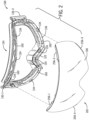
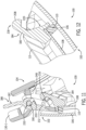
- an example goggle 100 includes a lens assembly 102 removably coupled to a goggle frame 104.
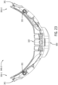
- the goggle 100 may be of a shield-type design including a single or unitary outer lens 106, which may be configured to extend in the field of view of both the left and right eyes of the user when worn.
- the outer lens 106 may be formed from a single lens blank and may thus be devoid of any seams or other discontinuities in the lens.
- the outer lens 106 may be made from polycarbonate (PC), acrylic, or other materials which can provide suitable optical qualities (e.g., optical clarity) to the optical portion of the eyewear.
- the outer lens 106 may be rimless or frameless in that a perimeter of the lens 106 is not substantially enclosed by a frame, as illustrated in FIG. 1 . These features may provide a larger unobstructed field of view through the outer lens 106.
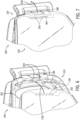
- the lens assembly 102 may include a spacer 110 (e.g., a foam spacer) that attaches the outer and inner lenses 106, 108 together.
- the spacer 110 may be positioned at least partially between the outer lens 106 and the inner lens 108, and may extend along a peripheral portion of the outer lens 106 and the inner lens 108 so as to provide a large unobstructed field of view through the outer lens 106 and the inner lens 108.
- the spacer 110 may include adhesive on both of its sides (i.e., its front and rear surfaces) to adhere the outer lens 106 to the inner lens 108.
- the spacer 110 may be implemented using a double-sided adhesive foam tape.
- the lens assembly 102 may include a lens frame 112 configured for removably coupling the lens assembly to the goggle frame 104.
- the lens frame 112 may support the inner lens 108 and/or the spacer 110.
- the lens frame 112 may define a seat 114 that receives and supports the spacer 110.
- a rear surface of the spacer 110 may abut against the seat 114 when the lens assembly 102 is assembled, and adhesive applied to the rear surface of the spacer 110 may adhere the spacer 110 to the lens frame 112.
- the lens frame 112 is formed of polycarbonate, and may be molded. The lens frame 112 may thus be relatively more rigid as compared to the relatively softer portions of the goggle frame 104 that are positioned conformally to the user's face.
- the goggle 100 may define a nose recess 120 (e.g., along a bottom periphery of the lens assembly 102), which may be configured to accommodate the nose of the wearer when the goggle 100 is worn.
- a nose pad 122 may be provided at the nose recess 120.
- the nose pad 122 may be formed from a soft or flexible polymeric material (e.g., thermoplastic elastomer (TPE), such as a thermoplastic polyurethane (TPU) material) which may conform to the user's nose for a comfortable fit and may optionally include one or more bendable portions for improved adjustability.
- TPE thermoplastic elastomer
- TPU thermoplastic polyurethane
- the nose pad 122 may form part of the goggle frame 104 (see FIG.
- the nose pad 122 may be removably attached to the lens assembly 102 or the goggle frame 104, such as to enable replacement of the nose pad 122.
- the goggle 100 may include first and second opposite end portions 124-1, 124-2.
- a strap 128 (such as an elastic headband) may be attached to each of the first and second end portions 124-1, 124-2 via first and second outriggers 130-1, 130-2, respectively (see FIGS. 1 and 8 ).
- Each outrigger 130-1, 130-2 may be pivotally coupled to the goggle frame 104 to provide a relatively customized fit of the strap 128 around a front portion of a wearer's head.
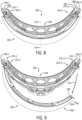
- the magnetic materials may be attached to opposing (e.g., facing) sides of the lens assembly 102 and the goggle frame 104 to urge the lens assembly 102 towards the goggle frame 104.
- the magnetic attraction between the magnetic materials on the lens assembly 102 and the goggle frame 104 may provide a centering function (e.g., resulting from the magnetic materials natural tendency to axially align their respective fields to one another), which may facilitate alignment of the lens assembly 102 to the goggle frame 104.
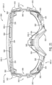
- the goggle frame 104 may include magnetic materials for magnetic coupling with corresponding magnetic materials on the lens assembly 102.
- the goggle frame 104 may include magnets 134 exposed along an angled surface 136 of the goggle frame 104.
- the magnets 134 may be arranged along a lower portion of the goggle frame 104 (such as generally beneath a wearer's eyes and adjacent the wearer's nose) and along an upper portion of the goggle frame 104 (such as adjacent a wearer's forehead).
- Several magnets 134 may be arranged adjacent the nose pad 122.
- the goggle frame 104 includes eight magnets 134, but in other embodiments the goggle frame 104 may include more or less than eight magnets 134.
- the magnets 134 may include an exposed surface that is substantially flush with the angled surface 136, which may be angled inward and rearward toward a center of the goggle frame 104 to facilitate alignment of the lens assembly 102 with the goggle frame 104.
- the magnets 134 may be oriented at about a forty-five degree angle (e.g., forty-five degrees plus or minus thirty degrees) to facilitate alignment of the lens assembly 102 with the goggle frame 104.
- the angled surface 136 and the magnets 134 are oriented at a forty-five degree angle relative to a plane defined by the curvature of the outer lens 106 to facilitate alignment of the lens assembly 102 with the goggle frame 104. In other embodiments, different arrangement (e.g., orientation) of the magnets with respect to the surface 136 may be used.
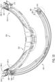
- the goggle frame 104 may include a face gasket and an interface component for interfacing with the removable lens assembly.
- the face gasket may be provided by one or more resiliently deformable components, which are configured to placed conformally to the user's face.
- the face gasket is provided by a frame ring 140.
- the interface component is implemented as an overmold component or material 142.
- the overmold material 142 may be formed of a relatively hard or rigid material (e.g., nylon) to form an interface component that provides a structural base for interfacing with the lens frame 112.
- the face gasket (e.g., frame ring 140) of the goggle frame 104 may be formed of a softer material (e.g., thermoplastic polyurethane (TPU)) for conformally interfacing with the wearer's face.
- TPU thermoplastic polyurethane
- the frame ring 140 which may be formed from the relatively more flexible material (e.g., TPU) for example by an injection molding process, may be overmolded by the relatively more rigid material (e.g., nylon) in an overmold process during which the interface component is shaped or formed while being joined to the frame ring.
- the interface component(s) may be formed first and the overmolded by the face gasket material.
- the magnets 134 are inserted into pockets 146 defined in the frame ring 140, and then the frame ring 140 is overmolded by the overmold material 142, thereby effectively molding the magnets 134 into the goggle frame 104.
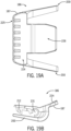
- the magnets 134 may be attached to the frame ring 140, such that the frame ring 140 counteracts the magnetic force imposed on the magnets 134 by the lens assembly 102 to ensure the magnets 134 are not pulled out of the goggle frame 104 during decoupling of the lens assembly 102 from the goggle frame 104. For example, as illustrated in FIG.
- the magnets 134 may include wings 148 extending from opposing ends of the magnets 134, and the wings 148 may be received within slots 150 formed in the frame ring 140 at opposing ends of the pockets 146.
- the overmold material 142 may cover at least a front portion of the frame ring 140 and at least a portion of the magnets 134 to lock the magnets 134 in place (e.g., restrict the wings 148 of the magnets 134 from sliding out of the slots 150 in the frame ring 140). At least a portion of a front surface of the magnets 134 may be exposed through the overmold material 142 to facilitate magnetic coupling of the magnets 134 with the lens assembly 102.
- the lens assembly 102 may include magnetic materials for magnetic coupling with corresponding magnetic materials on the goggle frame 104.
- the lens assembly 102 may include magnets 154 exposed along an angled surface 156 of the lens assembly 102.
- the magnets 154 may be arranged at corresponding locations to the magnets 134 of the goggle frame 104, and may include opposing polarities to the magnets 134 such that the magnets 134, 154 are attracted to each other.
- the magnets 154 may include an exposed surface that is substantially flush with the angled surface 156, which may be angled at a corresponding angle to the angled surface 136 of the goggle frame 104 to facilitate alignment of the lens assembly 102 with the goggle frame 104.
- the magnets 154 may be oriented at about a forty-five degree angle (e.g., forty-five degrees plus or minus thirty degrees) to facilitate alignment of the lens assembly 102 with the goggle frame 104.
- the angled surface 156 and the magnets 154 are oriented at a forty-five degree angle relative to a plane defined by the curvature of the inner lens 108 to facilitate alignment of the lens assembly 102 with the goggle frame 104.
- the magnets 154 may be received in pockets 158 defined in the lens frame 112.
- the magnets 154 may only be inserted into the pockets 158 from a front side of the lens frame 112, such that the lens frame 112 inhibits the magnets 154 from being pulled out of the lens assembly 102 during decoupling of the lens assembly 102 from the goggle frame 104.
- Each latch 180-1, 180-2 may be configured to cause the lever 187 to temporarily move (e.g., pivot) away from the tab 183 during attachment of the lens assembly 102 to the goggle frame 104.
- the lever 187 and/or the tab 183 may include ramp features which may cooperate to cause the lever 187 of each latch 180 to move from its latched position to its unlatched position as the lens assembly 102 is advanced toward the goggle frame 104, e.g., without the application of user force to the lever 187 other than the force applied to advance the lens assembly 102 toward the goggle frame 104.
- the tab 183 need not have a perimeter that defines a regular shape.
- the perimeter of the tab 183 may define any irregular shape as may be suitable for a particular application.
- the tab 183 may be differently shaped in other embodiments than the examples specifically illustrated or described.
- the latch component 186 may include a user-engagement portion 224 and a latch portion 228 as in the illustrated embodiment in FIG. 13 .
- the user-engagement portion 224 may be a generally plate-like structure configured for a wearer to press against to actuate the latch component 186 (e.g., move the lever 187 from its latched position to its unlatched position to enable removal of the lens assembly 102 from the goggle frame 104).
- the latch portion 228 may be angled or rounded at its forward end to define the ramp 204.
- the user-engagement portion 224 may be separated from the latch portion 228 by the fulcrum portion 232, which may define the aperture 231 for receiving the pivot pin or post 190.
- All the user may be required to do is move the lens assembly 102 close to the goggle frame 104, and the magnetic materials of the lens assembly 102 and the goggle frame 104 cooperate with one another to magnetically couple the lens assembly 102 to the goggle frame 104, which movement causes the lever 187 to open and close, thereby securing the lens assembly 102 to the goggle frame 104.
- the extensions 162 and recesses 160 may facilitate the proper alignment and positioning of the lens assembly 102 to the goggle frame 104.
- each outrigger may engage a stop 248 formed on the goggle frame 104 that prevents the outriggers (see outrigger 130-1 in FIG. 11 ) from pivotal movement towards the lever 187, thereby inhibiting the outriggers 130-1, 130-2 from actuating the levers 187.
- the biasing feature may enable the automatic return of the lever 187 to its latched position once the lever 187 has cleared the distal end of the tab 183.
- the wearer may grasp the free end 250 of the lens assembly 102 and move the lens assembly 102 in a lateral direction (see arrow 254 in FIG. 9 ) away from the engaged latch 170-1 to remove the lens assembly 102 from the goggle frame 104.
- moving the lens assembly 102 in the lateral direction allows removal of the tab 183 from behind the lever 187 without actuating the lever 187.
- the lens assembly 102 may be detached from the goggle frame 104 by actuation of only one of the latches 170-1, 170-2.
- the wearer may manually actuate one of the latches 170-1, 170-2 on one side of the goggle 100, pivot the lens assembly 102 about the other, non-actuated latch 170-1, 170-2 on the other side of the goggle 100 until the other latch disengages itself naturally without having to actuate the latch.
- the lens assembly 102 may be pivoted until all of the extensions 162 are removed from the recesses 160 (see FIGS. 2-5 ) and then may be laterally removed from the goggle frame 104.
- the lens assembly 102 is pivoted about twenty to thirty degrees to naturally disengage the other latch. The pivotal range may vary depending on the specific goggle application.
- the near effortless engagement of the lens assembly 102 to the goggle frame 104 in accordance with the present disclosure may enable the user to install and remove the lens assembly 102 without touching the lens surface (that is by only handling the lens assembly 102 by its edges), which may address some shortcomings of existing interchangeable goggle designs.
- the lens assembly 102 may include multiple user engagement features located around a periphery of the lens (e.g., outer lens 106 and/or inner lens 108) for a wearer to grasp during coupling or decoupling of the lens assembly 102 to or from, respectively, the goggle frame 104, thus avoiding touching the lens.
- the lens assembly 102 may include multiple rim portions 256 located around a periphery of the outer lens 106.
- the rim portions 256 may protrude outwardly from the outer lens 106 such that the rim portions 256 form a semi-rimless frame around the periphery of the outer lens 106 for a wearer to grasp during coupling or decoupling of the lens assembly 102 to or from, respectively, the goggle frame 104.
- the rim portions 256 may be located near the corners of the lens assembly 102 to facilitate handling of the lens assembly 102 by the wearer. For example, as illustrated in FIG.
- a first rim portion 256-1 and a fourth rim portion 256-4 may be located at opposing corners of one end- or side-portion of the lens assembly 102, and a second rim portion 256-2 and a third rim portion 256-3 may be located at opposing corners of the other end- or side-portion of the lens assembly 102.
- the wearer may grasp the first and fourth rim portions 256-1, 256-4 and/or the second and third rim portions 256-2, 256-3 to manipulate the lens assembly 102, such as to pivot one end of the lens assembly 102 away from the goggle frame 104 during removal of the lens assembly 102 from the goggle frame 104.
- the rim portions 256 may be formed on the lens frame 112 (see FIG.
- the lens assembly 102 illustrated in FIGS. 1-4 and 14 includes four rim portions 256-1, 256-2, 256-3, 256-4 (generally referred to as rim portions 256), the lens assembly 102 may include more or less than four rim portions.
- the lengths of the rim portions 256 along the periphery of the outer lens 106 may be longer or shorter than the rim portions 256 in the example shown in FIGS. 1-4 .
- FIGS. 16-18 illustrate a retention feature 260 in accordance with further embodiments of the present disclosure.
- the retention feature 260 may include a first latch component (e.g., a gate 262) and a second latch component (e.g., strips 264).
- the gate 262 may include (e.g., be formed at least partially of) a magnetic material (e.g., a permanent magnet such as a rare earth magnet, or ferromagnetic material such as iron or steel).
- Each strip 264 may include a magnet 266 (e.g., a magnetic material such as iron or a neodymium or other type of permanent magnet) affixed thereto, forming magnetic strips 264.
- Each magnet 266 may have the same polarity as each other such that the magnets 266 are configured to repel each other to maintain the strips 264 in a spaced-apart relationship defining a gap 268 therebetween.
- the gate 262 blocks the repelling force of the strips 264, and the magnetic strips 264 are magnetically attracted to the gate 262 (see FIG. 18 ) to secure the lens assembly 102 to the goggle frame 104.
- the second latch component may include a first magnetic strip 264 and the second magnetic strip 264 is built into goggle frame 104.
- side portions 342-1 and 342-2 may be coupled to upper frame ring 340-1 and lower frame ring 340-2 by an overmolding process.
- the side portions 342-1 and 342-2 are formed (e.g., by injection molding, compression molding or other suitable molding process or via an additive manufacturing process such as stereolithography (SLA) or other 3D printing process).
- SLA stereolithography
- the side portions are inserted into a mold tool where they are overmolded with the thermoplastic elastomer (e.g., TPU) of the face gasket.
- the magnets may then be inserted into pockets of the frame gasket.
- the face gasket component(s) and the interface component(s) may be each separately formed via a suitable process such as molding or additive manufacturing and the two separately formed components may be attached to one another via an adhesive and/or mechanical coupling (e.g., fasteners, snap features, etc.)
- the partial frame rings 340-1 and 340-2 may include one or more protrusions 341 at end portions 324-1 and 324-2 configured to engage cavities 339 formed in the side portions 342-1 and 342-2.
- the protrusions 341 may have a hook-like structure which may provide additional retention of the side portions 342-1 and 342-2 to the partial frame rings 340-1 and 340-2.
- upper frame ring 340-1 and lower frame ring 340-2 may include holes 331 near end portions 324-1 and 324-2 configured to receive prongs 333 of outriggers 330-1 and 330-2.
- the prongs 333 may retain outriggers 330-1 and 330-2 to the partial frame rings 340-1 and 340-2.
- the prongs 333 may rotate within holes 331, pivotally coupling the outriggers 330-1 and 330-2 to the goggle frame 304.
- the prongs 333 may be configured to engage holes 331 such that the outriggers 330-1 and 330-2 are fixedly attached to the partial frame rings 340-1 and 340-2.
- partial frame rings 340-1 and 340-2 may have angled surfaces 336-1 and 336-2.
- Angled surfaces 336-1 and 336-2 may be angled inward and rearward toward a center of the goggle frame 304 to facilitate alignment of the lens assembly 102 with the goggle frame 304.
- the angled surfaces 336-1 and 336-2 may be oriented at a forty-five degree angle relative to a plane defined by the curvature of the outer lens 106 to facilitate alignment of the lens assembly 102 with the goggle frame 304.
- the angled surfaces 336-1 and 336-2 may define recesses 360.
- the recesses 360 may be positioned and shaped to correspond with extensions 162 of lens assembly 102.
- the goggle frame 304 may include extensions and the lens assembly 102 may include recesses. The corresponding recesses and extensions may facilitate alignment between goggle frame 304 and lens assembly 102.
- goggle frame 304 may include magnetic materials (e.g., magnetic elements) for magnetic coupling with corresponding magnetic materials on the lens assembly 102.
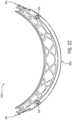
- partial frame rings 340-1 and 340-2 may include magnets 334 exposed along angled surfaces 336-1 and 336-2.
- the magnets 334 may be positioned to correspond to the positions of magnets 154 on lens assembly 102.
- the magnets 334 may have polarities opposite those of magnets 154 to facilitate coupling of lens assembly 102 and goggle frame 304.
- the magnets 334 may have a trapezoidal shape surface.
- Pockets 346 may be defined in the upper and lower frame rings 340-1 and 34-2 along angled surfaces 336-1 and 336-2 between adjacent recesses 360.
- the pockets 346 may have a generally trapezoidal shape oriented such that the opening of the pockets 346 at the angled surfaces 336-1 and 336-2 are smaller than the bottoms of the pockets 346.
- the shape of the pockets 346 may correspond to the trapezoidal shape of the magnets 334 such that the magnets 334 are retained in the pockets 346 and exposed surfaces of the magnets 334 are flush with the angled surfaces 336-1 and 336-2.
- the partial frame rings 340-1 and 340-2 may be temporarily deformed (e.g., bent) such that the opening to the pockets 346 are widened.
- the magnets 334 may be placed inside the pockets 346 during deformation and once the partial frame rings 340-1 and 340-2 are returned to their original shapes, the magnets 334 may be retained within the pockets 346. In some embodiments, an adhesive may be applied inside the pockets 346 to provide additional retention of the magnets 334 in the pockets 346.
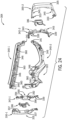
- goggle frame 304 is shown including seven magnets 334 in FIG. 21 , it is understood that goggle frame 304 may include more or fewer magnets 334 in other embodiments.
- goggle frame 304 may include additional retention features to secure lens assembly 102 to the goggle frame 304.
- goggle frame 304 may include retention features 370-1 and 370-2 located at side portions 342-1 and 342-2.
- the retention features 370-1 and 370-2 may be at least partially concealed by outriggers 330-1 and 330-2, respectively.
- the retention features 370-1 and 370-2 may comprise latches.
- the goggle 300 may include a first latch 380-1 and second latch 380-2.
- the latches 380-1 and 380-2 may be coupled to or proximate the side portions 342-1 and 342-2, respectively.
- Each latch 380-1 and 380-2 may include a first latch component 184 coupled to the lens assembly 102. That is, portion of the latch included with the lens assembly 102 may be the same as the latch component 184 described in reference to FIGS. 3 and 10-12 in some embodiments (e.g., tab 183).
- Each latch 380-1 and 380-2 may further include a second latch component 186 coupled to the goggle frame 304.
- the second latch component 186 may be the same as the latch component 186 shown in FIGS. 6-11 and 13 in some embodiments. In other embodiments, component 186 may be the same as the latch component 186 illustrated in FIGS. 19A and 19B . In the examples described in reference to FIGS. 20 , 24 and 25 , the latch component 186 of FIGS. 19A and 19B is shown.
- the second latch component 186 of each latch 180-1 and 180-2 may be movably coupled to the goggle frame 104 at side portions 342-1 and 342-2, respectively.
- Side portions 342-1 and 342-2 may each include a post 390.
- the aperture 231 may be configured to receive post 390 pivotally coupling the latch component 186 to the side portion 342.
- the post 390 may restrict movement of the latch component 186 lateral to the post 390.
- the side portion 342 may include lower wall 392 and upper wall 394 on opposite ends of the post 390.
- the lower wall 392 and upper wall 394 may restrict the up and down movement of the latch component 186.
- side portion 342 may include side wall 396 which may restrict pivotal movement of the latch component 186 and/or provide a base for arms 200 to apply a biasing force.
- portions of the partial frame rings 340 may be adjacent to the side wall 396 of the side portion 342.
- a portion of the arms 200 of the latch component 186 may apply a biasing force against the portions of the partial frame rings 340 adjacent to side wall 396.
- side portion 342 may include stops 343.
- stops 343 are in the form of flanges that angle outward from goggle frame 304.
- the outrigger 330 may include recesses 337 having shapes corresponding to stops 343.
- the stops 343 may restrict pivotal movement of outrigger 330 to prevent the outrigger 330 from actuating latch component 186 when the outrigger 330 is pivotally attached.
Landscapes
- Health & Medical Sciences (AREA)
- Ophthalmology & Optometry (AREA)
- Physics & Mathematics (AREA)
- Public Health (AREA)
- Engineering & Computer Science (AREA)
- Biomedical Technology (AREA)
- Heart & Thoracic Surgery (AREA)
- Vascular Medicine (AREA)
- Life Sciences & Earth Sciences (AREA)
- Animal Behavior & Ethology (AREA)
- General Health & Medical Sciences (AREA)
- Veterinary Medicine (AREA)
- Optics & Photonics (AREA)
- General Physics & Mathematics (AREA)
- Eyeglasses (AREA)
- Telescopes (AREA)
Claims (17)
- Brille (100), umfassend:
einen Brillenrahmen (104), umfassend:eine Gesichtsdichtung;eine Grenzflächenkomponente, die mit der Gesichtsdichtung gekoppelt ist;eine Vielzahl von ersten magnetischen Elementen (134), die mit einem oder beiden von der Gesichtsdichtung und der Grenzflächenkomponente gekoppelt und um einen Umfang des Brillenrahmens (104) herum beabstandet sind; undeine erste Verriegelungskomponente (186), die mit der Grenzflächenkomponente gekoppelt ist, wobei die erste Verriegelungskomponente einen Hebel umfasst, der schwenkbar mit der Grenzflächenkomponente gekoppelt ist; undeine Linsenanordnung, umfassend:eine äußere Linse (106);eine innere Linse (108), die von der äußeren Linse beabstandet und durch einen Abstandshalter (110) an dieser befestigt ist, um eine Doppellinsenstruktur (102) zu bilden, wobei ein Umfang des Abstandshalters über einen Umfang der inneren Linse hinausragt;einen Linsenrahmen (112), der mit der Doppellinsenstruktur (102) so gekoppelt ist, dass der Linsenrahmen (112) die innere Linse (108) und den Abstandshalter (110) stützt, wobei der Linsenrahmen (112) mit dem Umfang des Abstandshalters gekoppelt ist und sich entlang eines Umfangsabschnitts der inneren Linse (108) erstreckt, wodurch die innere Linse (108) zwischen dem Linsenrahmen (112) und dem Abstandshalter (110) festgehalten wird, und wobei der Linsenrahmen eine Anzahl von Magnetsitzen aufweist, die einer Anzahl der Vielzahl von ersten magnetischen Elementen entspricht;eine Vielzahl von zweiten magnetischen Elementen (154), wobei jedes in einem jeweiligen Magnetsitz auf dem Linsenrahmen so positioniert ist, dass die Vielzahl von zweiten magnetischen Elementen dazu ausgelegt ist, die Doppellinsenanordnung über magnetische Anziehung zwischen der ersten und der zweiten Vielzahl von magnetischen Elementen magnetisch mit dem Brillenrahmen zu koppeln; undeine zweite Verriegelungskomponente (184), die mit dem Linsenrahmen gekoppelt und dazu ausgelegt ist, mechanisch mit der ersten Verriegelungskomponente in Eingriff zu kommen, um die Doppellinsenanordnung lösbar am Brillenrahmen zu befestigen. - Brille nach Anspruch 1, wobei die Grenzflächenkomponente einen Stift (190) aufweist und der Hebel einen Drehpunktabschnitt umfasst, der eine Öffnung definiert, die dazu ausgelegt ist, den Stift darin aufzunehmen.
- Brille nach Anspruch 1 oder Anspruch 2, wobei der Brillenrahmen ferner einen Ausleger (130) umfasst, der schwenkbar mit der Grenzflächenkomponente gekoppelt ist, wobei der Ausleger eine gleiche Schwenkachse wie der Hebel aufweist.
- Brille nach Anspruch 3, wobei die Grenzflächenkomponente Anschläge aufweist, die verhindern, dass der Ausleger die erste Verriegelungskomponente betätigt.
- Brille nach Anspruch 3 oder Anspruch 4, wobei der Ausleger mindestens einen Teil der ersten Verriegelungskomponente vor der Sicht verdeckt.
- Brille nach einem der Ansprüche 1-5, wobei die erste Verriegelungskomponente so mit der Grenzflächenkomponente gekoppelt ist, dass die erste Verriegelungskomponente in Richtung einer verriegelten Stellung vorgespannt ist.
- Brille nach Anspruch 6, wobei die erste Verriegelungskomponente einen Hebel (187) umfasst, der mindestens einen Arm (200) aufweist, der an der Grenzflächenkomponente anliegt, um den Hebel in Richtung der verriegelten Stellung vorzuspannen.
- Brille nach einem der Ansprüche 1-7, wobei die Gesichtsdichtung einen oberen Rahmenring und einen unteren Rahmenring mit einem ersten und einem zweiten Endabschnitt umfasst, und die Grenzflächenkomponente einen ersten Seitenabschnitt und einen zweiten Seitenabschnitt umfasst, wobei der erste Seitenabschnitt mit dem oberen Rahmenring und dem unteren Rahmenring an dem ersten Endabschnitt gekoppelt ist und der zweite Seitenabschnitt mit dem oberen Rahmenring und dem unteren Rahmenring an dem zweiten Endabschnitt gekoppelt ist.
- Brille nach Anspruch 8, ferner umfassend einen ersten und einen zweiten Ausleger (130-1, 130-2), wobei der obere und der untere Rahmenring Löcher an dem ersten und dem zweiten Endabschnitt aufweisen, die dazu ausgelegt sind, Zinken des ersten und des zweiten Auslegers aufzunehmen, um den ersten und den zweiten Ausleger mit dem Brillenrahmen zu koppeln.
- Brille nach einem der Ansprüche 1-9, wobei einer von dem Brillenrahmen oder dem Linsenrahmen einen Vorsprung umfasst und der andere von dem Brillenrahmen und dem Linsenrahmen eine Aussparung umfasst, die dazu ausgelegt ist, in dem Vorsprung aufgenommen zu werden.
- Brille nach Anspruch 10, wobei sich die Aussparung in der Gesichtsdichtung befindet.
- Brille nach Anspruch 10, wobei sich die Aussparung in der Grenzflächenkomponente befindet.
- Brille nach einem der Ansprüche 1-12, wobei der Linsenrahmen ferner mindestens einen Randabschnitt umfasst, der so um einen Umfang der Linsenanordnung herum angeordnet ist, dass ein Träger den mindestens einen Randabschnitt greifen kann, um die Linsenanordnung von dem Brillenrahmen zu entfernen, ohne die äußere Linse oder innere Linse zu berühren.
- Brille nach einem der Ansprüche 1-13, wobei die Gesichtsdichtung einen oberen und einen unteren Rahmenring umfasst, die aus thermoplastischem Elastomer gebildet sind, und wobei eines oder mehrere der Vielzahl von ersten magnetischen Elementen mit mindestens einem des oberen und des unteren Rahmenrings gekoppelt sind.
- Brille nach einem der Ansprüche 1-14, wobei die erste Vielzahl von magnetischen Elementen des Brillenrahmens und die zweite Vielzahl von magnetischen Elementen der Linsenanordnung eine Trapezform aufweisen.
- Brille nach einem der Ansprüche 1-15, wobei der Hebel ferner eine Leiste umfasst und die zweite Verriegelungskomponente eine Lasche umfasst, die eine Schulter (216) aufweist, wobei die Schulter dazu ausgelegt ist, mit der Leiste (212) des Hebels in Eingriff zu kommen.
- Verfahren zum Entfernen einer Linsenanordnung von einem Brillenrahmen (104), wobei das Verfahren umfasst:Bereitstellen der Brille nach einem der Ansprüche 1 bis 16;Betätigen der ersten Verriegelung, die eines der gegenüberliegenden Enden der Linsenanordnung an dem Brillenrahmen befestigt, in eine entriegelte Stellung, um dieses Ende der Linsenanordnung von dem Brillenrahmen zu lösen;nach dem Betätigen der ersten Verriegelung Schwenken der Linsenanordnung um einen Stift der zweiten Verriegelung von dem Brillenrahmen weg, wobei die zweite Verriegelung das andere der gegenüberliegenden Enden der Linsenanordnung an dem Brillenrahmen befestigt; undnach dem Schwenken der Linsenanordnung seitliches Verschieben der Linsenanordnung von der zweiten Verriegelung weg, ohne die zweite Verriegelung zu betätigen, um die Linsenanordnung von dem Brillenrahmen zu entfernen.
Priority Applications (1)
| Application Number | Priority Date | Filing Date | Title |
|---|---|---|---|
| EP25158935.4A EP4537799A3 (de) | 2017-10-13 | 2018-10-15 | Brille mit auswechselbarer linse |
Applications Claiming Priority (1)
| Application Number | Priority Date | Filing Date | Title |
|---|---|---|---|
| US201762572260P | 2017-10-13 | 2017-10-13 |
Related Child Applications (2)
| Application Number | Title | Priority Date | Filing Date |
|---|---|---|---|
| EP25158935.4A Division EP4537799A3 (de) | 2017-10-13 | 2018-10-15 | Brille mit auswechselbarer linse |
| EP25158935.4A Division-Into EP4537799A3 (de) | 2017-10-13 | 2018-10-15 | Brille mit auswechselbarer linse |
Publications (2)
| Publication Number | Publication Date |
|---|---|
| EP3470028A1 EP3470028A1 (de) | 2019-04-17 |
| EP3470028B1 true EP3470028B1 (de) | 2025-03-26 |
Family
ID=63862068
Family Applications (2)
| Application Number | Title | Priority Date | Filing Date |
|---|---|---|---|
| EP18200538.9A Active EP3470028B1 (de) | 2017-10-13 | 2018-10-15 | Brille mit austauschbarer linse |
| EP25158935.4A Pending EP4537799A3 (de) | 2017-10-13 | 2018-10-15 | Brille mit auswechselbarer linse |
Family Applications After (1)
| Application Number | Title | Priority Date | Filing Date |
|---|---|---|---|
| EP25158935.4A Pending EP4537799A3 (de) | 2017-10-13 | 2018-10-15 | Brille mit auswechselbarer linse |
Country Status (4)
| Country | Link |
|---|---|
| US (2) | US10948746B2 (de) |
| EP (2) | EP3470028B1 (de) |
| CN (1) | CN109662826B (de) |
| CA (1) | CA3020818C (de) |
Families Citing this family (33)
| Publication number | Priority date | Publication date | Assignee | Title |
|---|---|---|---|---|
| US11048093B2 (en) * | 2017-02-22 | 2021-06-29 | Htc Corporation | Head-mounted display device |
| USD860301S1 (en) * | 2017-07-19 | 2019-09-17 | Lenovo (Beijing) Co., Ltd. | Smart glasses |
| CA3020818C (en) | 2017-10-13 | 2020-10-20 | Smith Optics, Inc. | Goggle with replaceable lens |
| USD868878S1 (en) | 2017-10-13 | 2019-12-03 | Smith Optics, Inc. | Goggle |
| US11833084B2 (en) * | 2018-03-02 | 2023-12-05 | 100% Speedlab, Llc | Goggle systems and methods |
| CA3132036A1 (en) * | 2018-03-02 | 2019-09-06 | 100% Speedlab, Llc | Goggle systems and methods |
| EP4609841A3 (de) | 2018-11-05 | 2025-11-05 | Smith Sport Optics, Inc. | Brillenlinse mit zusammengesetzter krümmung zur verbesserung des sichtfeldes nach unten |
| USD892913S1 (en) * | 2018-11-05 | 2020-08-11 | Smith Sport Optics, Inc. | Goggle |
| USD899502S1 (en) * | 2019-01-16 | 2020-10-20 | Guangzhou He Chang Optical Co., Ltd | Goggles |
| US11129431B2 (en) * | 2019-05-07 | 2021-09-28 | Bell Sports, Inc. | Magnetic goggle attachment |
| WO2020252508A1 (de) * | 2019-06-19 | 2020-12-24 | Rauter Christoph | Adaptervorrichtung für eine sichtscheibe zur optischen verglasung mit brillengläsern |
| TWD208902S (zh) * | 2019-07-10 | 2020-12-11 | 大陸商深圳市倍輕鬆科技股份有限公司 | 護眼儀 |
| USD907107S1 (en) * | 2019-07-29 | 2021-01-05 | 100% Speedlab, Llc | Goggles |
| USD909457S1 (en) * | 2019-08-01 | 2021-02-02 | Guangzhou Julong Sports Co., Ltd. | Goggles |
| USD906406S1 (en) * | 2019-08-28 | 2020-12-29 | Oakley, Inc. | Goggle |
| US11833083B2 (en) | 2019-12-20 | 2023-12-05 | Oakley, Inc. | Eyewear with integrally formed barrier |
| US11389330B2 (en) * | 2019-12-31 | 2022-07-19 | Spy Optic Inc. | Magnetic goggle lens changing system |
| US20210251717A1 (en) * | 2020-02-19 | 2021-08-19 | Globus Medical, Inc. | Extended reality headset opacity filter for navigated surgery |
| USD1025193S1 (en) * | 2020-02-26 | 2024-04-30 | Leatt Corporation | Strap for goggles |
| USD1022024S1 (en) * | 2020-02-26 | 2024-04-09 | Leatt Corporation | Strap for goggles |
| USD948598S1 (en) * | 2020-10-02 | 2022-04-12 | H&H Sports Protection S.R.L. | Goggles |
| IT202100001715U1 (it) * | 2021-04-02 | 2022-10-02 | Safilo Sa Fabbrica Italiana Lavorazione Occhiali Spa | Occhiali mono-lente a lente intercambiabile |
| USD979158S1 (en) * | 2021-06-17 | 2023-02-21 | Shenzhen Leshuo Technology Co., Ltd. | Pet glasses |
| USD1000506S1 (en) * | 2021-06-21 | 2023-10-03 | Binbin PAN | Goggle |
| US20230404203A1 (en) * | 2022-06-20 | 2023-12-21 | Clearview Systems, Llc | Detachably attachable sun visor for wire-frame sports face mask |
| USD1118743S1 (en) * | 2023-06-03 | 2026-03-17 | Apple Inc. | Display unit |
| USD1101020S1 (en) * | 2023-06-05 | 2025-11-04 | Apple Inc. | Display unit |
| USD1086270S1 (en) * | 2023-09-06 | 2025-07-29 | Yijia Optical Technology (Zhaoqing Huaiji) Co., LTD | Goggles |
| US20250123496A1 (en) * | 2023-10-11 | 2025-04-17 | Spoke & Piston | Quick lock and release attachment mechanism for glasses, goggles, and eyewear |
| US20250311803A1 (en) * | 2024-04-03 | 2025-10-09 | Jeff Torres | Visor for Helmut |
| US20250318957A1 (en) * | 2024-04-10 | 2025-10-16 | Tianqi Technology Co (Ningbo) Ltd | Goggle with interchangeable lenses |
| USD1109794S1 (en) * | 2024-06-17 | 2026-01-20 | Bolle Protection | Goggles with removable nosepiece and bi-material arms |
| USD1117388S1 (en) * | 2024-09-13 | 2026-03-10 | Hui-Hsuan CHIU YU | Eyeglass lens |
Family Cites Families (225)
| Publication number | Priority date | Publication date | Assignee | Title |
|---|---|---|---|---|
| US2508870A (en) | 1945-09-04 | 1950-05-23 | American Optical Corp | Detachable lens for one-piece channeled mountings |
| US3484156A (en) | 1967-06-22 | 1969-12-16 | American Allsafe Co | Welding goggles with removable protective lens cover |
| US3691565A (en) | 1970-11-25 | 1972-09-19 | Omnitech Inc | Flight deck goggle |
| US4026640A (en) | 1975-04-30 | 1977-05-31 | American Optical Corporation | Tennis players' spectacles |
| US4240718A (en) | 1978-01-26 | 1980-12-23 | Wicher Max F | Sports spectacle structure |
| US4968129A (en) | 1984-10-23 | 1990-11-06 | American Optical Corporation | Eyeglass frame structures and method of assembling same |
| US4730915A (en) | 1985-01-11 | 1988-03-15 | Oakley, Inc. | Detachable component sunglasses |
| US4699479A (en) | 1985-06-20 | 1987-10-13 | American Optical Corporation | Eyeglass frame structure and method of assembling same |
| US4878749A (en) | 1988-06-29 | 1989-11-07 | Mcgee James E | Protective eyewear with interchangeable decorative frames |
| US4964714A (en) | 1988-07-14 | 1990-10-23 | Gentex Corporation | Safety spectacles and temple therefor |
| US4998815A (en) | 1989-09-27 | 1991-03-12 | Lin David J T | Sunglass frame structure |
| US5013145A (en) | 1989-11-20 | 1991-05-07 | Croll Theodore P | Eyeglasses with liquid-filled lenses |
| US5170190A (en) | 1990-06-18 | 1992-12-08 | Berke Joseph J | Water sportsman's face mask for viewing objects above and below the line of vision |
| US5110199A (en) | 1991-02-01 | 1992-05-05 | Takeshi Ishida | Distortion free ophthalmic lens for presbyopia having wide range distinct views |
| USRE37816E1 (en) | 1991-08-28 | 2002-08-13 | Jon Kranhouse | Diving mask with lenses and method of fabricating the same |
| US5296583A (en) | 1992-07-09 | 1994-03-22 | University Of Michigan | Calcification-resistant synthetic biomaterials |
| JP2583057Y2 (ja) | 1992-09-16 | 1998-10-15 | 株式会社キャットアイ | 眼鏡用レンズ |
| GB2281635B (en) | 1993-09-01 | 1997-04-09 | Gentex Optics Inc | Aspheric sunglass or eye protector of substantially uniform thickness |
| US5432568A (en) | 1994-01-10 | 1995-07-11 | Foggles, Inc. | Eyewear having translucent superior and inferior fields of view |
| US5841505A (en) | 1994-08-01 | 1998-11-24 | Etablissements Bolle' S.N.C. | Sunglasses |
| US5452029A (en) | 1994-08-08 | 1995-09-19 | Yang; Tien | Eyeglass frame assembly |
| US5489953A (en) | 1994-09-28 | 1996-02-06 | Griffith; Gregory A. | Sighting lens for golfers |
| US5614964A (en) | 1995-03-13 | 1997-03-25 | 9001-6262 Quebec Inc. | Unitary spherical flexible eyewear pane having two separate individually optically compensating lens elements and eyewear for sportsmen having such a pane |
| US5617588A (en) | 1995-03-16 | 1997-04-08 | Uvex Safety, Inc. | Snap together protective goggle construction with toric lens |
| US5815848A (en) | 1995-07-14 | 1998-10-06 | Oakley, Inc. | Impact resistant face shield for sporting helmets |
| US5532767A (en) | 1995-07-19 | 1996-07-02 | Jackson Products, Inc. | Pantoscopic and length adjustable safety spectacle |
| US5594511A (en) | 1995-11-13 | 1997-01-14 | Mao Lin Enterprise Co., Ltd. | Eyeglasses with a lens-frame body which can be selectively coupled with either a pair of bows or a head strap |
| US5774201A (en) | 1995-12-05 | 1998-06-30 | Oakley, Inc. | Elliptical lens for eyewear |
| US5648832A (en) | 1995-12-05 | 1997-07-15 | Oakley, Inc. | Decentered noncorrective lens for eyewear |
| USD377036S (en) | 1996-01-26 | 1996-12-31 | Halo Sports And Safety, Inc. | Sports eyewear |
| US5703669A (en) | 1996-03-18 | 1997-12-30 | Park; James S. | Sunglasses including quick release lens retainer #5 |
| EP0900403B1 (de) | 1996-03-21 | 2003-05-28 | Sola International Holdings, Ltd. | Verbesserte einstärkenlinsen |
| US5909267A (en) | 1996-05-02 | 1999-06-01 | Cabot Safety Intermediate Corporation | Pantascopic adjustment mechanism for eyewear |
| US6254236B1 (en) | 1996-05-02 | 2001-07-03 | Cabot Safety Intermediate Corporation | Parabolic and hyperbolic aspheric eyewear |
| USD404416S (en) | 1997-03-03 | 1999-01-19 | Uvex Arbeitsschutz Gmbh | Protective eye glasses |
| US6149269A (en) | 1997-04-18 | 2000-11-21 | Madison; Julie B. | Eyeglasses having magnetically held auxiliary lenses |
| US6176576B1 (en) | 1997-06-06 | 2001-01-23 | Radians, Inc. | Eyewear supported by a wearer's concha of an ear |
| US5867841A (en) | 1997-08-27 | 1999-02-09 | Chiang; Herman | Ventilated sport goggle structure |
| IT1296696B1 (it) | 1997-11-28 | 1999-07-14 | Carrera Optyl Marketing Gmbh | Occhiali sportivi |
| US6105177A (en) | 1997-12-26 | 2000-08-22 | Paulson Manufacturing Corp. | Protective goggles |
| US6036315A (en) | 1998-03-18 | 2000-03-14 | Copeland; Victor L. | Optically superior decentered over-the-counter sunglasses |
| US6129435A (en) | 1998-04-09 | 2000-10-10 | Nike, Inc. | Decentered protective eyewear |
| WO1999063392A1 (en) | 1998-06-04 | 1999-12-09 | Sola International Holdings Ltd. | Shaped ophthalmic lenses |
| US6009564A (en) | 1998-06-24 | 2000-01-04 | Oakley, Inc. | Optically corrected goggle |
| US6505930B1 (en) | 1998-10-21 | 2003-01-14 | Sola International Holdings, Ltd. | Spectacles frames for shaped lens elements |
| KR20000026927A (ko) | 1998-10-24 | 2000-05-15 | 이범규 | 물안경의 자동밴드조절장치 |
| US6942337B2 (en) | 2001-11-08 | 2005-09-13 | Gary M. Zelman | Eyewear having both a primary lens frame and an auxiliary lens frame separately coupled to an eyewear platform |
| US6786593B2 (en) | 1998-11-02 | 2004-09-07 | Gary M. Zelman | Removable lens frame mounted to an eyewear platform |
| US6550913B2 (en) | 1998-11-02 | 2003-04-22 | Gary Martin Zelman | Auxiliary eyewear attachment methods and apparatus |
| US6585370B2 (en) | 1998-11-02 | 2003-07-01 | Gary M. Zelman | Removable lens frame mounted to an eyewear platform |
| US6053611A (en) | 1998-12-21 | 2000-04-25 | Ku; Kuo-Hseng | Eyeglass frame coupling system |
| US6098207A (en) | 1999-01-19 | 2000-08-08 | Burtin; Mayme L. | Protective eyewear |
| KR200215114Y1 (ko) | 1999-02-11 | 2001-03-02 | 손진현 | 엠피3 플레이어 기능을 구비한 이동통신 단말기 |
| USD424080S (en) | 1999-03-02 | 2000-05-02 | Cabot Safety Intermediate Corporation | Eyewear lens |
| USD428039S (en) | 1999-07-12 | 2000-07-11 | Oakley, Inc. | Goggle |
| US6343860B1 (en) | 1999-08-26 | 2002-02-05 | Greenhouse Grown Products, Inc. | Toric-shaped lenses and goggle assembly |
| US6250759B1 (en) | 1999-12-22 | 2001-06-26 | Peakvision, Llc | Eyeglass lens with multiple optical zones having varying optical properties for enhanced visualization of different scenes in outdoor recreational activities |
| US6253388B1 (en) | 1999-12-31 | 2001-07-03 | Ronald Lando | Eye wear with snap-together bridge |
| US6540352B2 (en) | 2000-02-22 | 2003-04-01 | Christian Dalloz Sunoptics | Noncorrective prism compensating lens and eyeglass provided with said lens |
| US6402318B1 (en) | 2000-04-15 | 2002-06-11 | Tony Xin Xiao | Magnetic shelter frame for glasses |
| US6325507B1 (en) | 2000-06-02 | 2001-12-04 | Oakley, Inc. | Eyewear retention system extending across the top of a wearer's head |
| US6601953B1 (en) | 2000-06-06 | 2003-08-05 | Viva Ip Corp. | Shelter frame kit for glasses |
| JP2002221694A (ja) | 2001-01-29 | 2002-08-09 | Kiyoshi Yamaguchi | 多焦点レンズ |
| US6994434B2 (en) | 2001-02-23 | 2006-02-07 | Cabot Safety Intermediate Corp. | Eyewear with lens hinge |
| US7039959B2 (en) * | 2001-04-30 | 2006-05-09 | John Dondero | Goggle for protecting eyes with movable single-eye lenses and methods for using the goggle |
| US20030142264A1 (en) | 2001-09-21 | 2003-07-31 | Roland Westerdal | Reading safety glasses |
| JP2005508524A (ja) | 2001-11-08 | 2005-03-31 | ゼルマン、ゲーリー、エム. | アイウェア・プラットフォームに取り付けられる着脱自在なレンズフレーム |
| US6592220B1 (en) | 2002-01-30 | 2003-07-15 | Lak Cheong | Eyeglass frame with removably mounted lenses |
| JP2004008496A (ja) | 2002-06-07 | 2004-01-15 | Pentax Corp | ゴーグル |
| US7140727B2 (en) | 2002-07-10 | 2006-11-28 | Isl Technologies, Llc | Eyeglass frame assembly |
| US20040046929A1 (en) | 2002-09-09 | 2004-03-11 | Foresight Optical Ltd. | Integrally formed pair of lenses for a pair of glasses |
| USD477010S1 (en) | 2002-11-01 | 2003-07-08 | Oakley, Inc. | Goggle and goggle component |
| US6893126B2 (en) | 2002-11-18 | 2005-05-17 | Intercast Usa, Inc. | Optical sheet for use in manufacturing a cylindrically shaped optically correct visor and method of manufacturing said visor |
| US6755522B1 (en) | 2002-12-12 | 2004-06-29 | Scott K. Strenk | Eyeglass and auxiliary frame assembly |
| US7073208B2 (en) | 2002-12-20 | 2006-07-11 | Jackson Products, Inc. | Ventilated safety goggles |
| AU2003901272A0 (en) | 2003-03-19 | 2003-04-03 | Martin Hogan Pty Ltd | Improvements in or relating to eyewear attachments |
| US6764175B1 (en) | 2003-04-22 | 2004-07-20 | Joy Chen | Plastic sunglasses with secondary optical glasses |
| MXPA05012123A (es) | 2003-05-30 | 2006-02-22 | Scient Optics Inc | Lentes de contacto con periferia modelada. |
| US7370961B2 (en) | 2003-10-02 | 2008-05-13 | Ira Lerner | Interchangeable eyewear assembly |
| US7237891B2 (en) | 2003-11-27 | 2007-07-03 | Kbc America, Inc. | Eyewear with removable shield |
| US7134752B2 (en) | 2003-12-03 | 2006-11-14 | Sola International Holdings Ltd. | Shaped non-corrective eyewear lenses and methods for providing same |
| US6991333B2 (en) | 2004-02-12 | 2006-01-31 | Nike, Inc. | Eyewear with replaceable lens |
| DE112005000658T5 (de) | 2004-03-22 | 2007-02-08 | Arena Industries, LLC (n.d.Ges.d.Staates Delaware), Lake Forest | Schutzbrillenlinse |
| JP4228966B2 (ja) | 2004-03-30 | 2009-02-25 | セイコーエプソン株式会社 | 眼鏡レンズ |
| US6964067B1 (en) | 2004-04-22 | 2005-11-15 | Utopia Optics International, Inc. | Hinged goggle |
| US7241007B2 (en) | 2004-06-01 | 2007-07-10 | Cody Thomas P | Convertible eyewear |
| US6926402B1 (en) | 2004-06-01 | 2005-08-09 | Lee-Tsung Chen | Three pieces combinative eyeglasses |
| USD515615S1 (en) | 2004-06-15 | 2006-02-21 | Cabot Safety Intermediate Corporation | Goggle |
| US7389543B2 (en) | 2004-06-30 | 2008-06-24 | Nike, Inc. | Optically decentered face shield |
| US7240370B2 (en) | 2004-07-08 | 2007-07-10 | Bruce Lerner | Cap attachable, adjustable sunglasses |
| US7040749B2 (en) | 2004-07-30 | 2006-05-09 | E'lite Optik U.S. L.P. | Auxiliary lens assembly with improved attachment to primary lens assembly |
| US7029114B2 (en) | 2004-09-03 | 2006-04-18 | E'lite Optik U.S. L.P. | Eyewear assembly with auxiliary frame and lens assembly |
| US20070261155A1 (en) | 2004-09-29 | 2007-11-15 | Safilo Societa Azionaria Fabbrica Italiana Lavorazione Occhiali S.P.A. | Mask-Form Goggles, Particularly for Sporting Use |
| DE102004059448A1 (de) | 2004-11-19 | 2006-06-01 | Rodenstock Gmbh | Verfahren und Vorrichtung zum Fertigen eines Brillenglases; System und Computerprogrammprodukt zum Fertigen eines Brillenglases |
| US7661815B2 (en) | 2005-05-12 | 2010-02-16 | Lipawsky Steven R | Eyeframe with interchangeable lenspieces held by a magnetic closure and interchangeable lens system |
| US7537336B2 (en) | 2005-06-27 | 2009-05-26 | Gary Martin Zelman | Lenses removably secured to an eyewear platform |
| CN100364242C (zh) | 2005-09-13 | 2008-01-23 | 浙江华立通信集团有限公司 | 可嵌入Rake接收机系统 |
| USD548251S1 (en) | 2005-09-13 | 2007-08-07 | Brass Eagle, Llc | Quick change extension contoured lens |
| US7407283B2 (en) | 2005-09-14 | 2008-08-05 | Fosta-Tek Optics, Inc. | Goggle lens, method of manufacturing same, and goggle containing same |
| US7797765B2 (en) | 2005-12-30 | 2010-09-21 | Bell Sports, Inc. | Lens replacement system |
| US8092007B2 (en) | 2006-01-13 | 2012-01-10 | Switch Vision, Llc | Eyewear frames with magnetic lens attachments |
| US8641188B2 (en) | 2006-01-13 | 2014-02-04 | Switch Vision, Llc | Eyewear frames with magnetic lens attachments |
| US20080304005A1 (en) | 2006-01-13 | 2008-12-11 | Dichiara Carmine S | Eyewear Frames With Mechanical Lock Lens Attachments |
| US7305719B2 (en) | 2006-01-18 | 2007-12-11 | Water Square Sports Co., Ltd. | Protective lenses with a flexible gasket assembly |
| US7207673B1 (en) | 2006-04-14 | 2007-04-24 | Alex Ho | Cap-mounted sun glasses |
| US7568797B2 (en) | 2006-05-24 | 2009-08-04 | Hibbs Jr Harry O | Protective facial shielding having magnetic rims |
| US7527373B2 (en) | 2006-06-06 | 2009-05-05 | 3M Innovative Properties Company | Safety eyewear |
| EP2024778A1 (de) | 2006-06-06 | 2009-02-18 | Safilo Societa' Azionaria Fabbrica Italiana Lavorazione Occhiali S.p.a. | Verfahren zur herstellung von brillen des einzellinsen-umklapptyps und mit dem verfahren produzierte brillen |
| US7403346B2 (en) | 2006-07-18 | 2008-07-22 | Nike, Inc. | Inclined-edged sports lens |
| JP4434182B2 (ja) | 2006-07-25 | 2010-03-17 | セイコーエプソン株式会社 | 眼鏡レンズの設計方法 |
| US7448750B2 (en) | 2006-09-22 | 2008-11-11 | Oakley, Inc. | Quadrilateral lens |
| US7347545B1 (en) | 2006-10-05 | 2008-03-25 | Oakley, Inc. | Sports-specific shield |
| US7497569B2 (en) | 2006-12-06 | 2009-03-03 | Bell Sports, Inc. | Partially entrapped frame having a removable lens |
| US20080189838A1 (en) | 2007-02-12 | 2008-08-14 | Mage Jerome J M | Multi-base lens goggle |
| US7784937B2 (en) | 2007-06-05 | 2010-08-31 | Digital Vision, Inc. | System and method of surfacing a lens, such as a lens for use with eyeglasses |
| US8316470B2 (en) * | 2007-08-09 | 2012-11-27 | Smith Optics, Inc. | Eyewear lens attachment system and method |
| US7520605B1 (en) | 2008-03-10 | 2009-04-21 | Chih-Ming Chen | Eyewear with magnetic connection between lenses and frame |
| US8555425B2 (en) | 2008-05-07 | 2013-10-15 | Nike, Inc. | Aquatic goggles |
| US7971995B2 (en) | 2008-05-09 | 2011-07-05 | Oakley, Inc. | Net-molded optical articles and methods of making the same |
| KR101681657B1 (ko) | 2008-06-13 | 2016-12-12 | 군나르 옵틱스, 엘엘씨 | 컴퓨터 시각 증후군의 증상들을 감소시키기 위한 저배율 아이웨어 |
| US7967431B2 (en) | 2008-09-23 | 2011-06-28 | Siu Yu | Spectacles |
| FR2936879B1 (fr) | 2008-10-07 | 2011-03-11 | Essilor Int | Verre ophtalmique corrigeant la vision foveale et la vision peripherique. |
| USD606112S1 (en) | 2008-10-17 | 2009-12-15 | Aaron Markovitz | Eyeglasses |
| US8192015B2 (en) | 2009-01-09 | 2012-06-05 | Oakley, Inc. | Eyeglass with enhanced ballistic resistance |
| US8469510B2 (en) | 2009-01-09 | 2013-06-25 | Oakley, Inc. | Eyewear with enhanced ballistic resistance |
| JP5286473B2 (ja) | 2009-03-31 | 2013-09-11 | ホーヤ レンズ マニュファクチャリング フィリピン インク | 累進屈折力眼鏡レンズの設計方法 |
| US7941874B2 (en) | 2009-04-11 | 2011-05-17 | Terry Chou | Swimming or diving goggles |
| US8480226B2 (en) | 2009-07-22 | 2013-07-09 | Nonu Ifergan | Frame construction for eyewear |
| US20110273661A1 (en) | 2009-08-10 | 2011-11-10 | High Rainbow Ent. Co., Ltd. | Eyeglasses |
| WO2011026038A1 (en) | 2009-08-31 | 2011-03-03 | Peter Arnell | Interchangeable and customizable eyewear |
| US9241527B2 (en) | 2009-09-03 | 2016-01-26 | Revision Military S.A.R.L. | Ballistic and impact protective visor system for military helmet assembly |
| US8192019B2 (en) | 2009-12-07 | 2012-06-05 | Roger Wen-Yi Hsu | Wraparound corrective lens |
| EP2521521B1 (de) | 2010-01-08 | 2016-11-09 | Scott Sports S.A. | System zur passformanpassung |
| US20110199680A1 (en) | 2010-01-22 | 2011-08-18 | Oakley, Inc. | Eyewear with three-dimensional viewing capability |
| US8020987B2 (en) * | 2010-02-02 | 2011-09-20 | T-Link Ppe Ltd. | Sunglasses structure |
| US20120038878A1 (en) | 2010-02-11 | 2012-02-16 | Derrick Artips Echevarria | Decorative Eyewear |
| AU2013202394B2 (en) | 2010-03-19 | 2014-10-02 | Oakley, Inc. | Eyewear |
| SG184119A1 (en) | 2010-03-19 | 2012-10-30 | Oakley Inc | Eyewear |
| AU2011289179A1 (en) | 2010-08-13 | 2013-03-14 | Oakley, Inc. | Eyewear with lens retention mechanism |
| USD640724S1 (en) | 2010-10-18 | 2011-06-28 | Oakley, Inc. | Goggle |
| USD649577S1 (en) | 2011-01-18 | 2011-11-29 | Oakley, Inc. | Goggle |
| AT510580B1 (de) | 2011-01-28 | 2012-05-15 | Silhouette International Schmied Ag | Brille |
| US8025396B1 (en) | 2011-03-23 | 2011-09-27 | Clic Goggles, Inc. | Magnetic eyewear latch mechanism |
| US8917459B2 (en) | 2011-05-23 | 2014-12-23 | Eric A. Klein | Ergonomic vertical vision redirection |
| USD653686S1 (en) | 2011-06-24 | 2012-02-07 | Dragon Alliance | Snow and sand shield |
| EA027482B1 (ru) | 2011-06-24 | 2017-07-31 | Дрэгн Алайнс, Ллк | Спортивные очки |
| JP5934798B2 (ja) | 2011-09-22 | 2016-06-15 | オークリー インコーポレイテッド | アイウェアのための取り付けメカニズム |
| USD657812S1 (en) | 2011-10-12 | 2012-04-17 | Borrion Enterprise Co., Ltd. | Ski goggles |
| KR200471400Y1 (ko) | 2011-10-31 | 2014-02-19 | 주식회사 한국 오.지.케이 | 고글의 렌즈 탈,부착장치 |
| US9170432B2 (en) | 2011-11-30 | 2015-10-27 | Carl Zeiss Vision International Gmbh | Low distortion eyewear lens with low optical power |
| US9122078B2 (en) | 2011-12-01 | 2015-09-01 | Oakley, Inc. | Releasable earstem mounting mechanism for eyewear |
| US20130185849A1 (en) | 2012-01-24 | 2013-07-25 | The Burton Corporation | Magnetic goggle lens attachment |
| US9104043B2 (en) | 2012-03-09 | 2015-08-11 | Switch Vision Llc | Detachable lenses for eyewear |
| DE102012102743B4 (de) | 2012-03-29 | 2014-09-11 | Carl Zeiss Vision International Gmbh | Verfahren zum Auslegen eines Brillenglases und Brillenglas |
| USD714378S1 (en) | 2012-04-04 | 2014-09-30 | Spy Optic Inc. | Sports goggle |
| USD670753S1 (en) | 2012-05-07 | 2012-11-13 | Chun-Nan Chen | Pair of skiing goggles |
| DE102012010221A1 (de) | 2012-05-23 | 2013-11-28 | Carl Zeiss Vision International Gmbh | Verfahren zum Herstellen einer Brillenlinse mit astigmatischer Korrektur und Brille mit solcher Brillenlinse |
| US9192520B2 (en) | 2012-08-31 | 2015-11-24 | Oakley, Inc. | Eyewear having multiple ventilation states |
| WO2014039521A1 (en) | 2012-09-04 | 2014-03-13 | Armand Kidouchim | Eye wear hinge and process for assembly |
| USD729303S1 (en) | 2012-10-29 | 2015-05-12 | Salomon S.A.S. | Sports eyewear |
| USD695818S1 (en) | 2012-11-08 | 2013-12-17 | Atomic Austria Gmbh | Sports eyewear |
| USD695335S1 (en) | 2012-11-29 | 2013-12-10 | Oakley, Inc. | Goggle component |
| US20140182754A1 (en) | 2012-12-04 | 2014-07-03 | Lara N. Young | Goggle Cover with Integrated Storage Container |
| WO2014093514A1 (en) | 2012-12-11 | 2014-06-19 | Oakley, Inc. | Eyewear with outriggers |
| CN202966144U (zh) | 2012-12-12 | 2013-06-05 | 四川大学 | 一种汽车左侧和右侧的后视镜 |
| USD694806S1 (en) | 2013-01-09 | 2013-12-03 | Jerome Jacques Marie Mage | Goggle |
| US20150351468A9 (en) | 2013-03-01 | 2015-12-10 | Bruce Chinquee | Face Mask |
| US20140300854A1 (en) | 2013-04-08 | 2014-10-09 | Mountain Shades, Inc. | Eyeglasses with lens securing mechanism for facilitating removable lenses |
| USD723094S1 (en) | 2013-07-03 | 2015-02-24 | Bor Jye Enterprise Co., Ltd. | Goggles |
| DE102013218136B3 (de) | 2013-09-11 | 2015-02-12 | Carl Zeiss Vision International Gmbh | Brillenglas-Halb- oder -Fertigfabrikat, Verfahren zu dessen Herstellung und Verfahren zum Beschichten eines Brillenglas-Halb- oder -Fertigfabrikats |
| US9585791B2 (en) | 2013-11-06 | 2017-03-07 | I-Design (9045-6278 Quebec Inc.) | Lens for protection of one or more eyes of a user, method of designing eyewear, and method of manufacturing eyewear |
| US20150143619A1 (en) * | 2013-11-26 | 2015-05-28 | Adam Paul Cross | Lens assembly |
| KR101531684B1 (ko) | 2013-12-04 | 2015-06-26 | 한승윤 | 고글 |
| USD718369S1 (en) | 2013-12-13 | 2014-11-25 | Oakley, Inc. | Goggle |
| USD715350S1 (en) | 2013-12-13 | 2014-10-14 | Oakley, Inc. | Goggle |
| US20150202088A1 (en) | 2014-01-22 | 2015-07-23 | Zeal Optics, Inc. | All-Weather Goggle |
| USD711961S1 (en) | 2014-02-07 | 2014-08-26 | Electric Visual Evolution Llc | Goggle |
| USD730430S1 (en) | 2014-02-24 | 2015-05-26 | Mastrad, S.A. | Processing goggles for produce |
| US10285861B2 (en) | 2014-03-28 | 2019-05-14 | Carl Zeiss Vision Italia S.P.A. | Ski goggles having a large field of vision |
| US9645414B2 (en) | 2014-05-22 | 2017-05-09 | Perriquest Defense Research Enterprises, Llc | Laser protection eyewear |
| US9864212B2 (en) | 2014-05-22 | 2018-01-09 | Carl Zeiss Vision International Gmbh | Method for reducing the thickness of a lens shape and uncut lens blank |
| USD725690S1 (en) | 2014-06-24 | 2015-03-31 | Oakley, Inc. | Eyeglass lens |
| EP2965728B1 (de) | 2014-07-10 | 2021-03-31 | Carl Zeiss Vision Italia S.p.A. | Skibrille mit auswechselbarer Nasenbrücke |
| US20160026004A1 (en) | 2014-07-23 | 2016-01-28 | Brent Sheldon | Eyewear having magnetic clip-on lenses |
| US9341865B2 (en) | 2014-07-23 | 2016-05-17 | Brent Sheldon | Eyewear having magnetic clip-on lenses |
| US9895266B2 (en) | 2014-10-16 | 2018-02-20 | Spy Optic Inc. | Goggle lens changing system |
| US20160327810A1 (en) * | 2014-11-26 | 2016-11-10 | Adam Paul Cross | Lens assembly |
| USD741858S1 (en) | 2015-01-20 | 2015-10-27 | Microsoft Corporation | Portion of headset with optical display element |
| USD741323S1 (en) | 2015-01-20 | 2015-10-20 | Microsoft Corporation | Headset with transparent visor |
| KR101545611B1 (ko) | 2015-02-25 | 2015-08-19 | 주식회사 한국 오.지.케이 | 광학 굴절을 방지하는 무도수 렌즈 제조방법 |
| WO2016182097A1 (ko) | 2015-05-12 | 2016-11-17 | 주식회사 제이텍 | 고글 |
| US9943444B2 (en) | 2015-05-15 | 2018-04-17 | Portal Instruments, Inc. | Goggle system and method |
| USD776187S1 (en) | 2015-05-15 | 2017-01-10 | Bern Unlimited Inc. | Goggle system |
| USD785699S1 (en) | 2015-08-14 | 2017-05-02 | Chun-Nan Chen | Goggle |
| US9364718B1 (en) | 2015-08-27 | 2016-06-14 | Roka Sports, Inc. | Goggles with retroscopic lens angle for enhanced forward vision |
| USD805576S1 (en) | 2015-09-15 | 2017-12-19 | Oakley, Inc. | Goggle |
| USD774123S1 (en) | 2015-09-16 | 2016-12-13 | Oakley, Inc. | Goggle |
| USD769350S1 (en) | 2015-09-18 | 2016-10-18 | Abominable Labs, Llc | Sport goggle |
| USD777826S1 (en) | 2015-09-29 | 2017-01-31 | Oakley, Inc. | Goggle |
| US10687981B2 (en) | 2015-10-09 | 2020-06-23 | Oakley, Inc. | Headworn supports with passive venting and removable lens |
| US10111780B2 (en) | 2015-10-23 | 2018-10-30 | Abominable Labs, Llc | Goggle lens and face gasket engagement system |
| USD783697S1 (en) | 2015-10-26 | 2017-04-11 | Oakley, Inc. | Lens |
| GB2544294B (en) | 2015-11-11 | 2021-06-09 | Ruroc Ip Holdings Ltd | Goggles for snowsports |
| KR101725218B1 (ko) | 2015-11-18 | 2017-04-12 | 주식회사 스포컴 | 프레임에 내부렌즈가 결합된 시야확장형 스키 고글 |
| US20190142639A1 (en) | 2016-04-25 | 2019-05-16 | Fox Head, Inc. | Attachment system for a lens to goggles |
| USD811664S1 (en) | 2016-05-11 | 2018-02-27 | D-H-G Knauer GmbH | Tiltable sunscreen |
| USD827208S1 (en) | 2016-05-23 | 2018-08-28 | Marlybag | Ski helmet visor |
| CN206080839U (zh) | 2016-06-21 | 2017-04-12 | 广州市钜保运动用品有限公司 | 一种滑雪眼镜快速更换镜片的结构 |
| FR3053968A1 (fr) | 2016-07-13 | 2018-01-19 | Biomerieux | Reactifs pour la protection reversible de molecules biologiques |
| USD821037S1 (en) | 2016-07-20 | 2018-06-19 | Innovgas Pty Ltd | Surgical eye shield |
| CN206261719U (zh) | 2016-08-24 | 2017-06-20 | 广州市益佳光学技术有限公司 | 快速换片滑雪眼镜 |
| USD834087S1 (en) | 2016-10-31 | 2018-11-20 | Oakley, Inc. | Goggle |
| USD828866S1 (en) | 2016-10-31 | 2018-09-18 | Oakley, Inc. | Goggle |
| USD818031S1 (en) | 2016-11-02 | 2018-05-15 | Oakley, Inc. | Google component |
| US10456299B2 (en) | 2016-12-15 | 2019-10-29 | Maui Jim, Inc. | Goggles with interchangeable lens attachment |
| US10197814B2 (en) | 2017-03-03 | 2019-02-05 | Smith Optics, Inc. | Magnetic attachment mechanism for eyewear |
| CN106618852A (zh) | 2017-03-15 | 2017-05-10 | 武林宁 | 一种方便拆卸镜片的滑雪眼镜 |
| USD827007S1 (en) | 2017-04-28 | 2018-08-28 | Oakley, Inc. | Lens |
| USD827690S1 (en) | 2017-05-01 | 2018-09-04 | Oakley, Inc. | Eyeglass lens |
| CN110997083B (zh) | 2017-06-26 | 2022-05-24 | 鹦鹉螺公司 | 可收纳的健身椅 |
| US11234867B2 (en) * | 2017-08-01 | 2022-02-01 | Spy Optic Inc. | Goggle lens changing system |
| CA3020818C (en) | 2017-10-13 | 2020-10-20 | Smith Optics, Inc. | Goggle with replaceable lens |
| USD868878S1 (en) | 2017-10-13 | 2019-12-03 | Smith Optics, Inc. | Goggle |
| EP3701320A4 (de) | 2017-10-24 | 2021-07-28 | Ashby, Brandon | Trainingslinse für sichtfeldbeobachtung |
| EP4609841A3 (de) | 2018-11-05 | 2025-11-05 | Smith Sport Optics, Inc. | Brillenlinse mit zusammengesetzter krümmung zur verbesserung des sichtfeldes nach unten |
-
2018
- 2018-10-12 CA CA3020818A patent/CA3020818C/en active Active
- 2018-10-12 US US16/159,316 patent/US10948746B2/en active Active
- 2018-10-15 EP EP18200538.9A patent/EP3470028B1/de active Active
- 2018-10-15 EP EP25158935.4A patent/EP4537799A3/de active Pending
- 2018-10-15 CN CN201811198747.7A patent/CN109662826B/zh active Active
-
2021
- 2021-03-15 US US17/202,156 patent/US12601933B2/en active Active
Also Published As
| Publication number | Publication date |
|---|---|
| CN109662826A (zh) | 2019-04-23 |
| CN109662826B (zh) | 2021-11-02 |
| EP3470028A1 (de) | 2019-04-17 |
| US20190113773A1 (en) | 2019-04-18 |
| EP4537799A3 (de) | 2025-06-18 |
| US12601933B2 (en) | 2026-04-14 |
| US20210236338A1 (en) | 2021-08-05 |
| EP4537799A2 (de) | 2025-04-16 |
| CA3020818A1 (en) | 2019-04-13 |
| CA3020818C (en) | 2020-10-20 |
| US10948746B2 (en) | 2021-03-16 |
Similar Documents
| Publication | Publication Date | Title |
|---|---|---|
| EP3470028B1 (de) | Brille mit austauschbarer linse | |
| US10935812B2 (en) | Magnetic attachment mechanism for eyewear | |
| US20240004222A1 (en) | Goggle lens with compound curvature for downward field of view enhancement | |
| US20160026003A1 (en) | Eyewear having magnetic clip-on lenses | |
| JP7619573B2 (ja) | 磁気ゴーグルレンズ交換システム | |
| US9104043B2 (en) | Detachable lenses for eyewear | |
| US20160026004A1 (en) | Eyewear having magnetic clip-on lenses | |
| EP3740178B1 (de) | Brille | |
| EP4372456A1 (de) | Brillenlinsenbefestigungssystem |
Legal Events
| Date | Code | Title | Description |
|---|---|---|---|
| PUAI | Public reference made under article 153(3) epc to a published international application that has entered the european phase |
Free format text: ORIGINAL CODE: 0009012 |
|
| STAA | Information on the status of an ep patent application or granted ep patent |
Free format text: STATUS: THE APPLICATION HAS BEEN PUBLISHED |
|
| AK | Designated contracting states |
Kind code of ref document: A1 Designated state(s): AL AT BE BG CH CY CZ DE DK EE ES FI FR GB GR HR HU IE IS IT LI LT LU LV MC MK MT NL NO PL PT RO RS SE SI SK SM TR |
|
| AX | Request for extension of the european patent |
Extension state: BA ME |
|
| STAA | Information on the status of an ep patent application or granted ep patent |
Free format text: STATUS: REQUEST FOR EXAMINATION WAS MADE |
|
| 17P | Request for examination filed |
Effective date: 20191017 |
|
| RBV | Designated contracting states (corrected) |
Designated state(s): AL AT BE BG CH CY CZ DE DK EE ES FI FR GB GR HR HU IE IS IT LI LT LU LV MC MK MT NL NO PL PT RO RS SE SI SK SM TR |
|
| STAA | Information on the status of an ep patent application or granted ep patent |
Free format text: STATUS: EXAMINATION IS IN PROGRESS |
|
| 17Q | First examination report despatched |
Effective date: 20230504 |
|
| P01 | Opt-out of the competence of the unified patent court (upc) registered |
Effective date: 20230522 |
|
| GRAP | Despatch of communication of intention to grant a patent |
Free format text: ORIGINAL CODE: EPIDOSNIGR1 |
|
| STAA | Information on the status of an ep patent application or granted ep patent |
Free format text: STATUS: GRANT OF PATENT IS INTENDED |
|
| INTG | Intention to grant announced |
Effective date: 20241021 |
|
| GRAS | Grant fee paid |
Free format text: ORIGINAL CODE: EPIDOSNIGR3 |
|
| GRAA | (expected) grant |
Free format text: ORIGINAL CODE: 0009210 |
|
| STAA | Information on the status of an ep patent application or granted ep patent |
Free format text: STATUS: THE PATENT HAS BEEN GRANTED |
|
| AK | Designated contracting states |
Kind code of ref document: B1 Designated state(s): AL AT BE BG CH CY CZ DE DK EE ES FI FR GB GR HR HU IE IS IT LI LT LU LV MC MK MT NL NO PL PT RO RS SE SI SK SM TR |
|
| REG | Reference to a national code |
Ref country code: GB Ref legal event code: FG4D |
|
| REG | Reference to a national code |
Ref country code: CH Ref legal event code: EP |
|
| REG | Reference to a national code |
Ref country code: DE Ref legal event code: R096 Ref document number: 602018080419 Country of ref document: DE |
|
| REG | Reference to a national code |
Ref country code: IE Ref legal event code: FG4D |
|
| PG25 | Lapsed in a contracting state [announced via postgrant information from national office to epo] |
Ref country code: RS Free format text: LAPSE BECAUSE OF FAILURE TO SUBMIT A TRANSLATION OF THE DESCRIPTION OR TO PAY THE FEE WITHIN THE PRESCRIBED TIME-LIMIT Effective date: 20250626 |
|
| PG25 | Lapsed in a contracting state [announced via postgrant information from national office to epo] |
Ref country code: FI Free format text: LAPSE BECAUSE OF FAILURE TO SUBMIT A TRANSLATION OF THE DESCRIPTION OR TO PAY THE FEE WITHIN THE PRESCRIBED TIME-LIMIT Effective date: 20250326 |
|
| REG | Reference to a national code |
Ref country code: LT Ref legal event code: MG9D |
|
| PG25 | Lapsed in a contracting state [announced via postgrant information from national office to epo] |
Ref country code: NO Free format text: LAPSE BECAUSE OF FAILURE TO SUBMIT A TRANSLATION OF THE DESCRIPTION OR TO PAY THE FEE WITHIN THE PRESCRIBED TIME-LIMIT Effective date: 20250626 |
|
| PG25 | Lapsed in a contracting state [announced via postgrant information from national office to epo] |
Ref country code: HR Free format text: LAPSE BECAUSE OF FAILURE TO SUBMIT A TRANSLATION OF THE DESCRIPTION OR TO PAY THE FEE WITHIN THE PRESCRIBED TIME-LIMIT Effective date: 20250326 |
|
| PG25 | Lapsed in a contracting state [announced via postgrant information from national office to epo] |
Ref country code: LV Free format text: LAPSE BECAUSE OF FAILURE TO SUBMIT A TRANSLATION OF THE DESCRIPTION OR TO PAY THE FEE WITHIN THE PRESCRIBED TIME-LIMIT Effective date: 20250326 |
|
| PG25 | Lapsed in a contracting state [announced via postgrant information from national office to epo] |
Ref country code: GR Free format text: LAPSE BECAUSE OF FAILURE TO SUBMIT A TRANSLATION OF THE DESCRIPTION OR TO PAY THE FEE WITHIN THE PRESCRIBED TIME-LIMIT Effective date: 20250627 Ref country code: BG Free format text: LAPSE BECAUSE OF FAILURE TO SUBMIT A TRANSLATION OF THE DESCRIPTION OR TO PAY THE FEE WITHIN THE PRESCRIBED TIME-LIMIT Effective date: 20250326 |
|
| REG | Reference to a national code |
Ref country code: NL Ref legal event code: MP Effective date: 20250326 |
|
| PG25 | Lapsed in a contracting state [announced via postgrant information from national office to epo] |
Ref country code: NL Free format text: LAPSE BECAUSE OF FAILURE TO SUBMIT A TRANSLATION OF THE DESCRIPTION OR TO PAY THE FEE WITHIN THE PRESCRIBED TIME-LIMIT Effective date: 20250326 |
|
| PG25 | Lapsed in a contracting state [announced via postgrant information from national office to epo] |
Ref country code: SE Free format text: LAPSE BECAUSE OF FAILURE TO SUBMIT A TRANSLATION OF THE DESCRIPTION OR TO PAY THE FEE WITHIN THE PRESCRIBED TIME-LIMIT Effective date: 20250326 |
|
| REG | Reference to a national code |
Ref country code: AT Ref legal event code: MK05 Ref document number: 1778327 Country of ref document: AT Kind code of ref document: T Effective date: 20250326 |
|
| PG25 | Lapsed in a contracting state [announced via postgrant information from national office to epo] |
Ref country code: SM Free format text: LAPSE BECAUSE OF FAILURE TO SUBMIT A TRANSLATION OF THE DESCRIPTION OR TO PAY THE FEE WITHIN THE PRESCRIBED TIME-LIMIT Effective date: 20250326 |
|
| PG25 | Lapsed in a contracting state [announced via postgrant information from national office to epo] |
Ref country code: PT Free format text: LAPSE BECAUSE OF FAILURE TO SUBMIT A TRANSLATION OF THE DESCRIPTION OR TO PAY THE FEE WITHIN THE PRESCRIBED TIME-LIMIT Effective date: 20250728 Ref country code: ES Free format text: LAPSE BECAUSE OF FAILURE TO SUBMIT A TRANSLATION OF THE DESCRIPTION OR TO PAY THE FEE WITHIN THE PRESCRIBED TIME-LIMIT Effective date: 20250326 |
|
| PG25 | Lapsed in a contracting state [announced via postgrant information from national office to epo] |
Ref country code: PL Free format text: LAPSE BECAUSE OF FAILURE TO SUBMIT A TRANSLATION OF THE DESCRIPTION OR TO PAY THE FEE WITHIN THE PRESCRIBED TIME-LIMIT Effective date: 20250326 |
|
| PGFP | Annual fee paid to national office [announced via postgrant information from national office to epo] |
Ref country code: IT Payment date: 20250926 Year of fee payment: 8 |
|
| PGFP | Annual fee paid to national office [announced via postgrant information from national office to epo] |
Ref country code: GB Payment date: 20250918 Year of fee payment: 8 |
|
| PG25 | Lapsed in a contracting state [announced via postgrant information from national office to epo] |
Ref country code: AT Free format text: LAPSE BECAUSE OF FAILURE TO SUBMIT A TRANSLATION OF THE DESCRIPTION OR TO PAY THE FEE WITHIN THE PRESCRIBED TIME-LIMIT Effective date: 20250326 |
|
| PGFP | Annual fee paid to national office [announced via postgrant information from national office to epo] |
Ref country code: FR Payment date: 20250922 Year of fee payment: 8 |
|
| PG25 | Lapsed in a contracting state [announced via postgrant information from national office to epo] |
Ref country code: EE Free format text: LAPSE BECAUSE OF FAILURE TO SUBMIT A TRANSLATION OF THE DESCRIPTION OR TO PAY THE FEE WITHIN THE PRESCRIBED TIME-LIMIT Effective date: 20250326 |
|
| PG25 | Lapsed in a contracting state [announced via postgrant information from national office to epo] |
Ref country code: RO Free format text: LAPSE BECAUSE OF FAILURE TO SUBMIT A TRANSLATION OF THE DESCRIPTION OR TO PAY THE FEE WITHIN THE PRESCRIBED TIME-LIMIT Effective date: 20250326 |
|
| PG25 | Lapsed in a contracting state [announced via postgrant information from national office to epo] |
Ref country code: SK Free format text: LAPSE BECAUSE OF FAILURE TO SUBMIT A TRANSLATION OF THE DESCRIPTION OR TO PAY THE FEE WITHIN THE PRESCRIBED TIME-LIMIT Effective date: 20250326 |
|
| PG25 | Lapsed in a contracting state [announced via postgrant information from national office to epo] |
Ref country code: IS Free format text: LAPSE BECAUSE OF FAILURE TO SUBMIT A TRANSLATION OF THE DESCRIPTION OR TO PAY THE FEE WITHIN THE PRESCRIBED TIME-LIMIT Effective date: 20250726 |
|
| REG | Reference to a national code |
Ref country code: DE Ref legal event code: R097 Ref document number: 602018080419 Country of ref document: DE |
|
| PGFP | Annual fee paid to national office [announced via postgrant information from national office to epo] |
Ref country code: DE Payment date: 20250916 Year of fee payment: 8 |
|
| PG25 | Lapsed in a contracting state [announced via postgrant information from national office to epo] |
Ref country code: DK Free format text: LAPSE BECAUSE OF FAILURE TO SUBMIT A TRANSLATION OF THE DESCRIPTION OR TO PAY THE FEE WITHIN THE PRESCRIBED TIME-LIMIT Effective date: 20250326 |
|
| PG25 | Lapsed in a contracting state [announced via postgrant information from national office to epo] |
Ref country code: CZ Free format text: LAPSE BECAUSE OF FAILURE TO SUBMIT A TRANSLATION OF THE DESCRIPTION OR TO PAY THE FEE WITHIN THE PRESCRIBED TIME-LIMIT Effective date: 20250326 |
|
| PLBE | No opposition filed within time limit |
Free format text: ORIGINAL CODE: 0009261 |
|
| STAA | Information on the status of an ep patent application or granted ep patent |
Free format text: STATUS: NO OPPOSITION FILED WITHIN TIME LIMIT |
|
| REG | Reference to a national code |
Ref country code: CH Ref legal event code: L10 Free format text: ST27 STATUS EVENT CODE: U-0-0-L10-L00 (AS PROVIDED BY THE NATIONAL OFFICE) Effective date: 20260211 |
|
| 26N | No opposition filed |
Effective date: 20260105 |