EP3469877A1 - Erntevorsatz für mähdrescher - Google Patents
Erntevorsatz für mähdrescher Download PDFInfo
- Publication number
- EP3469877A1 EP3469877A1 EP18200451.5A EP18200451A EP3469877A1 EP 3469877 A1 EP3469877 A1 EP 3469877A1 EP 18200451 A EP18200451 A EP 18200451A EP 3469877 A1 EP3469877 A1 EP 3469877A1
- Authority
- EP
- European Patent Office
- Prior art keywords
- wing
- header
- draper belt
- cutterbar
- coupled
- Prior art date
- Legal status (The legal status is an assumption and is not a legal conclusion. Google has not performed a legal analysis and makes no representation as to the accuracy of the status listed.)
- Granted
Links
- 239000000463 material Substances 0.000 claims abstract description 25
- 230000000712 assembly Effects 0.000 description 5
- 238000000429 assembly Methods 0.000 description 5
- 241001124569 Lycaenidae Species 0.000 description 3
- 238000003306 harvesting Methods 0.000 description 2
- 238000004140 cleaning Methods 0.000 description 1
- 238000010276 construction Methods 0.000 description 1
- 239000007787 solid Substances 0.000 description 1
Images


Classifications
-
- A—HUMAN NECESSITIES
- A01—AGRICULTURE; FORESTRY; ANIMAL HUSBANDRY; HUNTING; TRAPPING; FISHING
- A01D—HARVESTING; MOWING
- A01D61/00—Elevators or conveyors for binders or combines
- A01D61/02—Endless belts
-
- A—HUMAN NECESSITIES
- A01—AGRICULTURE; FORESTRY; ANIMAL HUSBANDRY; HUNTING; TRAPPING; FISHING
- A01D—HARVESTING; MOWING
- A01D34/00—Mowers; Mowing apparatus of harvesters
- A01D34/01—Mowers; Mowing apparatus of harvesters characterised by features relating to the type of cutting apparatus
- A01D34/02—Mowers; Mowing apparatus of harvesters characterised by features relating to the type of cutting apparatus having reciprocating cutters
- A01D34/03—Mowers; Mowing apparatus of harvesters characterised by features relating to the type of cutting apparatus having reciprocating cutters mounted on a vehicle, e.g. a tractor, or drawn by an animal or a vehicle
- A01D34/04—Mowers; Mowing apparatus of harvesters characterised by features relating to the type of cutting apparatus having reciprocating cutters mounted on a vehicle, e.g. a tractor, or drawn by an animal or a vehicle with cutters at the front
-
- A—HUMAN NECESSITIES
- A01—AGRICULTURE; FORESTRY; ANIMAL HUSBANDRY; HUNTING; TRAPPING; FISHING
- A01D—HARVESTING; MOWING
- A01D41/00—Combines, i.e. harvesters or mowers combined with threshing devices
- A01D41/12—Details of combines
- A01D41/14—Mowing tables
-
- A—HUMAN NECESSITIES
- A01—AGRICULTURE; FORESTRY; ANIMAL HUSBANDRY; HUNTING; TRAPPING; FISHING
- A01D—HARVESTING; MOWING
- A01D61/00—Elevators or conveyors for binders or combines
- A01D61/002—Elevators or conveyors for binders or combines transversal conveying devices
-
- A—HUMAN NECESSITIES
- A01—AGRICULTURE; FORESTRY; ANIMAL HUSBANDRY; HUNTING; TRAPPING; FISHING
- A01D—HARVESTING; MOWING
- A01D67/00—Undercarriages or frames specially adapted for harvesters or mowers; Mechanisms for adjusting the frame; Platforms
Definitions
- the disclosure relates to combine harvesters, and specifically to headers for combine harvesters.
- Combine harvesters commonly include headers that are used to cut and move crop material from a field into a body of the combine harvester, where the crop material is then further processed.
- a header for a combine harvester includes a center section having a first draper belt configured to move crop material in a first direction.
- the header also includes a wing pivotably coupled to the center section about a pivot axis and extending laterally away from the center section.
- the header also includes a second draper belt coupled to the wing and configured to move crop material in a second direction different than the first direction.
- the wing and the second draper belt are in a fixed positional relationship with each other, such that the wing is configured to remain at a constant distance from the second draper belt at all points along the wing during pivoting movement of the wing.
- a header for a combine harvester includes a center section having a first draper belt configured to move crop material in a first direction.
- the header also includes a wing pivotably coupled to the center section about a pivot axis and extending laterally away from the center section.
- the header also includes a second draper belt coupled to the wing and configured to move crop material in a second direction different than the first direction.
- the second draper belt is configured to move concurrently with the wing during pivoting movement of the wing.
- a header for a combine harvester includes a center section having a first draper belt configured to move crop material in a first direction.
- the header also includes a wing pivotably coupled to the center section about a pivot axis and extending laterally away from the center section.
- the header also includes a second draper belt coupled to the wing and configured to move crop material in a second direction different than the first direction.
- the header further includes a cutterbar coupled to the wing.
- the cutterbar includes a cutterbar support and reciprocating blades coupled to the cutterbar support.
- the cutterbar and the second draper belt are in a fixed positional relationship with each other, such that the cutterbar is configured to remain at a constant distance from the second draper belt at all points along the cutterbar during pivoting movement of the wing.
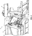
- a combine harvester 10 includes a front end 14 and a removable header 18 located at the front end 14 to cut crop material and feed the crop material into a housing 22 for further harvest processing (e.g., threshing of crop grains from plant stalks and separating or cleaning crop grains from chaffs so that the crop grains alone are harvested).
- the header 18 includes a center section 26 that couples the header 18 to the housing 22.
- the header 18 also includes wings 30 (e.g., cutter wings or harvesting wings) that are independently pivotably supported on opposite lateral sides of the center section 26.
- the wings 30 are identical in size and shape, although in other embodiments one of the wings 30 has a different size and/or shape than the other wing 30. In some embodiments, one or more of the wings 30 is laterally longer than the center section 26 along a lateral direction 33.
- each wing 30 includes a wing frame 32 and at least one actuator 34(e.g., hydraulic actuator, pneumatic actuator, or other actuator) and linkage assembly 38 coupled to the actuator 34 and to the wing 30 (e.g., to the wing frame 32).
- the actuator 34 and linkage assembly 38 link the wing 30 to the center section 26, and generate the pivoting movement of the wing 30 relative to the center section 26.
- Other embodiments include various other actuators and/or linkage assemblies that generate pivoting movement of the wings 30, as well as different numbers of actuators 34 and linkage assemblies 38, and different locations of actuators 34 and linkage assemblies 38 than that illustrated.
- the wings 30 may then be rotationally locked (e.g., via pins or other structures) in place at the desired angles. This adjustment permits the wings 30 to be positioned as close to the ground as possible as the crop harvester 10 moves through the field, thereby collecting a greater quantity of crop.
- the operator controls the pivoting movement of the wings 30.
- a controller may control (e.g., via automatic adjustment) the pivoting movement of the wings 30.
- the header 18 further includes belts (e.g., solid, flexible, elastomeric belts) to feed the cut crop material into the housing 22.
- each wing 30 includes a single side draper belt 42 coupled thereto, the side draper belt 42 extending substantially or entirely along a lateral length of the wing 30.
- the single side draper belt 42 is operable to transmit the cut crop material laterally inwardly toward the center section 26.
- the single side draper belts 42 are endless belts moved and/or guided via rollers 46 at laterally inward ends of the side draper belts 42, as well as by additional rollers 47 at opposite ends of the side draper belts 42.
- one or more actuators drive the side draper belts 42 about the rollers 46 and/or drive rotation of the rollers 46 themselves.
- the rollers 46 are located generally adjacent opposite lateral sides of the center section 26, and are supported by roller supports 48 ( FIG. 9 ).
- the center section 26 further includes an additional draper belt 50 (illustrated schematically) operable to transmit the cut crop material in a direction perpendicular to the side draper belts 42 (i.e., toward the housing 22 illustrated in FIG. 1 ) and opposite to a direction of travel 54 ( FIG. 1 ) of the combine harvester 10.
- the additional draper belt 50 is also an endless belt that rotates about rollers (not illustrated).
- the side draper belts 42 on the wings 30 work together to initially transmit the cut crop material laterally inwardly toward the center section 26, and the additional draper belt 50 works to receive the cut crop material from the side draper belts 42 and to transmit the cut crop material into the housing 22.
- Other embodiments include different numbers, arrangements, and types of draper belts 42, 50 than that illustrated.
- the wings 30 pivot about pivot axes 58.
- the pivot axes 58 extend directly through the rollers 46 and roller supports 48, and are coincident with longitudinal axes of the rollers 46, such that the entire wings 30 and their entire associated side draper belts 42 pivot together about the pivot axes 58.
- the wings 30 do not have any additional pivoting or flexing components (i.e., the entire wings 30 pivot only about the pivot axes 58), and the single side draper belts 42 on each wing 30 are the only draper belts on the wings 30.
- each side draper belt 42 remains at a constant distance or position relative to its respective wing 30 at all times during operation, and remains in a constant configuration or profile (e.g., circulating oval profile) at all times during operation. More specifically, the rollers 46, 47 of each draper belt 42 remain at a constant distance, position, and orientation with respect to each other during operation. The draper belts 42 also maintain a constant belt length through movement of the associated wing 30.
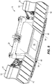
- the header 18 further includes cutterbars 62 associated with the wings 30 that each include a cutterbar support 66, and a plurality of laterally reciprocating, overlapping blades 70 coupled to the cutterbar support 66.
- the blades 70 cut through crops and generate the crop material described above.
- Other embodiments include different numbers and arrangements of cutterbar supports 66 and blades 70 than that illustrated.
- each cutterbar support 66 includes a first, pivot end 74 (e.g., sleeve) that is pivotally coupled to a bearing 78 ( FIG. 11 ) extending axially from one of the rollers 46, and a second end (not shown) that is fixed to a laterally outer end 82 ( FIGS.
- the pivot axes 58 extend through the bearings 78 such that the entire cutterbars 62 are pivotable about the same pivot axes 58 as the wings 30.
- a portion of the blades 70 may extend laterally inwardly from the pivot end 74 of the cutterbar support 66 and alongside a main frame 76 of the center section 26.
- the wings 30 maintain fixed positional relationships with the side draper belts 42 during pivoting movement of the wings 30 (e.g., remain at a constant distance from the side draper belts 42 at all points along the wings 30, resulting in uniform and concurrent movement of both the wings 30 and the side draper belts 42, and in some embodiments resulting in the wings 30 and the side draper belts 42 acting as single uniform body that pivots about the pivot axis 58).
- the cutterbars 62 also maintain fixed positional relationships with the wings 30 during pivoting movement of the wings 30 (e.g., remain at a constant distance from the wings 30 at all points along the cutterbars 62, resulting in uniform and concurrent movement of both the wings 30 and the cutterbars 62, and in some embodiments resulting in the wings 30 and the cutterbars 62 acting as single uniform body that pivots about the pivot axis58).
- the cutterbars 62 also maintain fixed positional relationships with the single side draper belts 42 during pivoting movement of the wings 30 (e.g., remain at a constant distance from the side draper belts 42 at all points along the cutterbars 62, resulting in uniform and concurrent movement of both the side draper belts 42 and the cutterbars 62, and in some embodiments resulting in the side draper belts 42 and the cutterbars 62 acting as single uniform body that pivots about the pivot axis 58).
- These fixed positional relationships permit crop material to continuously flow from the blades 70 onto the side draper belts 42 regardless of a rotational position of the wings 30.
- the header 18 also includes at least one rotating reel 86 that engages standing crops as the combine harvester 10 moves forward through a field.
- the reels 86 include center arms 90 ( FIGS. 3-6 ) and teeth 94 ( FIG. 1 , the teeth 94 not shown in FIGS. 3-6 ) disposed about the center arms 90 that engage and pull the crops toward the cutterbars 62 and the side draper belts 42.
- the teeth 94 may be rods, hooks, or any other suitable structures.
- the center arms 90 are telescoping structures (e.g., telescoping tubes) to permit the center arms 90 to extend and retract in length (e.g., as illustrated in FIGS. 3-6 ).
- portions of the center arms 90 and/or teeth 94 are driven rotationally via an actuator (e.g., a hydraulic actuator).
- the center arms 90 are coupled to the wings 30 at brackets 98 at the laterally outer ends 82 of the wings 30, the brackets 98 being coupled to first pivoting support arms 100.
- the wings 30 are also coupled to second pivoting support arms 102 on the center section 26.
- the pivoting support arms 100, 102 permit the reels 86 to be moved generally toward and away from the side draper belts 42, respectively, depending on whether use of the reels 86 is desired or whether access to the side draper belts 42 (or cutterbars 62) is desired.
- the pivoting support arms 100, 102 are moved via one or more actuators (e.g., hydraulic actuators, pneumatic actuators, etc.).
- the reels 86 When the reels 86 have been moved toward the side draper belts 42 and are adjacent the side draper belts 42, the reels 86 maintain fixed positional relationships with the side draper belts 42 during pivoting movement of the wings 30 (e.g., remain at a constant distance from the side draper belts 42 at all points along the reels 86, resulting in uniform and concurrent movement of both the side draper belts 42 and the reels 86, and in some embodiments resulting in the side draper belts 42 and the reels 86 acting as single uniform bodies that pivot about the pivot axes 58).
- the combine harvester 10 moves through a field.
- the operator or controller
- the side draper belt 42 moves uniformly with the wing 30 (as does the cutterbar 62).
- the wing 30, the side draper belt 42, and the cutterbar 62 all rotate together about the pivot axis 58.
- the reel 86 also moves with the wing 30, such that a distance between the reel 86 and the side draper belt 42 remains constant. This uniform movement of the wing 30, the side draper belt 42, the cutterbar 62, and the reel 86 helps to maintain consistent crop movement onto the side draper belt 42, and inhibits loss of crop material that is moving toward the side draper belt 42.
Landscapes
- Life Sciences & Earth Sciences (AREA)
- Environmental Sciences (AREA)
- Zoology (AREA)
- Harvester Elements (AREA)
- Harvesting Machines For Root Crops (AREA)
- Harvesting Machines For Specific Crops (AREA)
Applications Claiming Priority (1)
| Application Number | Priority Date | Filing Date | Title |
|---|---|---|---|
| US15/784,983 US10645877B2 (en) | 2017-10-16 | 2017-10-16 | Draper belt header with pivoting wings |
Publications (2)
| Publication Number | Publication Date |
|---|---|
| EP3469877A1 true EP3469877A1 (de) | 2019-04-17 |
| EP3469877B1 EP3469877B1 (de) | 2021-06-09 |
Family
ID=63862030
Family Applications (1)
| Application Number | Title | Priority Date | Filing Date |
|---|---|---|---|
| EP18200451.5A Active EP3469877B1 (de) | 2017-10-16 | 2018-10-15 | Erntevorsatz für mähdrescher |
Country Status (3)
| Country | Link |
|---|---|
| US (1) | US10645877B2 (de) |
| EP (1) | EP3469877B1 (de) |
| BR (1) | BR102018071157B1 (de) |
Cited By (3)
| Publication number | Priority date | Publication date | Assignee | Title |
|---|---|---|---|---|
| WO2021046077A1 (en) * | 2019-09-03 | 2021-03-11 | Cnh Industrial America Llc | Harvesting header segment display and map |
| EP3804494A1 (de) * | 2019-10-11 | 2021-04-14 | Carl Geringhoff GmbH & Co. KG | Schneidwerk mit in horizontaler richtung verstellbarer haspel |
| US20220007577A1 (en) * | 2018-11-16 | 2022-01-13 | Cnh Industrial America Llc | Header with modular rigid frame |
Families Citing this family (5)
| Publication number | Priority date | Publication date | Assignee | Title |
|---|---|---|---|---|
| WO2020101940A1 (en) * | 2018-11-16 | 2020-05-22 | Cnh Industrial America Llc | Harvester header with tilted top beam |
| CA190292S (en) * | 2019-05-09 | 2021-02-26 | Deere & Co | Fender for an agricultural machine |
| US11019770B2 (en) * | 2019-05-28 | 2021-06-01 | Deere & Company | Harvester wing leveling configuration |
| US11627701B2 (en) * | 2019-10-31 | 2023-04-18 | Deere & Company | Agricultural header with flexible joint |
| US20220369556A1 (en) * | 2021-05-19 | 2022-11-24 | Deere & Company | Agricultural header reel position control based on header wing position |
Citations (2)
| Publication number | Priority date | Publication date | Assignee | Title |
|---|---|---|---|---|
| US8087224B1 (en) * | 2010-09-16 | 2012-01-03 | Deere & Company | Flexible draper platform with pivot geometry |
| EP3398426A1 (de) * | 2017-04-30 | 2018-11-07 | Deere & Company | Multilink-verbindung zwischen erntekopfadapterrahmen und hauptrahmen |
Family Cites Families (10)
| Publication number | Priority date | Publication date | Assignee | Title |
|---|---|---|---|---|
| US6202397B1 (en) | 1999-05-27 | 2001-03-20 | Deere & Company | Draper belt tensioning mechanism for a harvesting platform |
| US20020129591A1 (en) * | 2001-03-19 | 2002-09-19 | Patterson Roger L. | Crop stripper for the crop transport draper of a header |
| US7549280B2 (en) | 2006-03-02 | 2009-06-23 | Deere & Company | Sectionalized belt guide for draper belt in an agricultural harvesting machine |
| US7478521B2 (en) * | 2006-03-02 | 2009-01-20 | Deere & Company | Flexible cutting platform to follow ground contour in an agricultural harvesting machine |
| US7614206B2 (en) * | 2007-06-04 | 2009-11-10 | Claas Selbstfahrende Erntemaschinen Gmbh | Winged header apparatus and method for a combine |
| US8752359B2 (en) * | 2012-08-31 | 2014-06-17 | Macdon Industries Ltd. | Draper support of a crop harvesting header |
| CA2799093A1 (en) * | 2012-12-18 | 2014-06-18 | Honey Bee Manufacturing Ltd. | Draper seal for crop header |
| US10412891B2 (en) * | 2017-01-23 | 2019-09-17 | Cnh Industrial America Llc | Draper belt system with differently sized rollers |
| US10477768B2 (en) * | 2017-05-23 | 2019-11-19 | Cnh Industrial America Llc | Extendable draper belt |
| US10440888B2 (en) * | 2017-06-30 | 2019-10-15 | Cnh Industrial America Llc | Draper belt system with distance change of pivoting roller |
-
2017
- 2017-10-16 US US15/784,983 patent/US10645877B2/en active Active
-
2018
- 2018-10-15 BR BR102018071157-1A patent/BR102018071157B1/pt active IP Right Grant
- 2018-10-15 EP EP18200451.5A patent/EP3469877B1/de active Active
Patent Citations (2)
| Publication number | Priority date | Publication date | Assignee | Title |
|---|---|---|---|---|
| US8087224B1 (en) * | 2010-09-16 | 2012-01-03 | Deere & Company | Flexible draper platform with pivot geometry |
| EP3398426A1 (de) * | 2017-04-30 | 2018-11-07 | Deere & Company | Multilink-verbindung zwischen erntekopfadapterrahmen und hauptrahmen |
Cited By (3)
| Publication number | Priority date | Publication date | Assignee | Title |
|---|---|---|---|---|
| US20220007577A1 (en) * | 2018-11-16 | 2022-01-13 | Cnh Industrial America Llc | Header with modular rigid frame |
| WO2021046077A1 (en) * | 2019-09-03 | 2021-03-11 | Cnh Industrial America Llc | Harvesting header segment display and map |
| EP3804494A1 (de) * | 2019-10-11 | 2021-04-14 | Carl Geringhoff GmbH & Co. KG | Schneidwerk mit in horizontaler richtung verstellbarer haspel |
Also Published As
| Publication number | Publication date |
|---|---|
| BR102018071157A2 (pt) | 2019-05-07 |
| US10645877B2 (en) | 2020-05-12 |
| US20190110403A1 (en) | 2019-04-18 |
| BR102018071157B1 (pt) | 2023-11-14 |
| EP3469877B1 (de) | 2021-06-09 |
Similar Documents
| Publication | Publication Date | Title |
|---|---|---|
| US10645877B2 (en) | Draper belt header with pivoting wings | |
| EP2420128B1 (de) | Flexibler Streckbandantrieb für eine landwirtschaftliche Erntemaschine | |
| US8640434B2 (en) | Removable corn header snout | |
| US10375882B2 (en) | Multi-sectional header frame | |
| US20220071090A1 (en) | Reel assembly of an agricultural header | |
| EP2769612A1 (de) | Kegelstumpfförmiger Förderer mit zurückziehbaren Fingern | |
| EP3657932B1 (de) | Transportbandanordnung für eine landwirtschaftliche erntemaschine | |
| EP3437455B1 (de) | Verstellbare förderanlage für erntevorsatz einer landwirtschaftlichen erntemaschine | |
| US10477765B2 (en) | Rotatable coupler for a reel arm of a reel header | |
| US9516816B2 (en) | Multiple drums conveyor for an agricultural platform | |
| EP3434097B1 (de) | Halmteiler für den erntevorsatz einer landwirtschaftlichen erntemaschine mit mehreren erntehaspeln | |
| US20120042618A1 (en) | Tilting Crop Stalk Chopper | |
| EP3069595B1 (de) | Vorsatz für eine landwirtschaftliche erntemaschine mit doppeltem schneidwerk | |
| US20200275609A1 (en) | Cam Track Adjustment Assembly for a Harvesting Reel | |
| US20230026343A1 (en) | Universal Crop Head Assembly and its Use in Harvesting Crops | |
| US20220279723A1 (en) | Rotatable wing dividers, harvesting headers, and agricultural machines having rotatable wing dividers | |
| US11140826B2 (en) | Feederhouse assembly having a rotational shaft with fluid passages | |
| CA3218822A1 (en) | Auger drive assembly for an agricultural harvester | |
| JP5313749B2 (ja) | コンバイン | |
| JPH01222717A (ja) | コンバインの穀稈掻込装置 |
Legal Events
| Date | Code | Title | Description |
|---|---|---|---|
| PUAI | Public reference made under article 153(3) epc to a published international application that has entered the european phase |
Free format text: ORIGINAL CODE: 0009012 |
|
| STAA | Information on the status of an ep patent application or granted ep patent |
Free format text: STATUS: THE APPLICATION HAS BEEN PUBLISHED |
|
| AK | Designated contracting states |
Kind code of ref document: A1 Designated state(s): AL AT BE BG CH CY CZ DE DK EE ES FI FR GB GR HR HU IE IS IT LI LT LU LV MC MK MT NL NO PL PT RO RS SE SI SK SM TR |
|
| AX | Request for extension of the european patent |
Extension state: BA ME |
|
| STAA | Information on the status of an ep patent application or granted ep patent |
Free format text: STATUS: REQUEST FOR EXAMINATION WAS MADE |
|
| 17P | Request for examination filed |
Effective date: 20191017 |
|
| RBV | Designated contracting states (corrected) |
Designated state(s): AL AT BE BG CH CY CZ DE DK EE ES FI FR GB GR HR HU IE IS IT LI LT LU LV MC MK MT NL NO PL PT RO RS SE SI SK SM TR |
|
| GRAJ | Information related to disapproval of communication of intention to grant by the applicant or resumption of examination proceedings by the epo deleted |
Free format text: ORIGINAL CODE: EPIDOSDIGR1 |
|
| GRAP | Despatch of communication of intention to grant a patent |
Free format text: ORIGINAL CODE: EPIDOSNIGR1 |
|
| GRAP | Despatch of communication of intention to grant a patent |
Free format text: ORIGINAL CODE: EPIDOSNIGR1 |
|
| STAA | Information on the status of an ep patent application or granted ep patent |
Free format text: STATUS: GRANT OF PATENT IS INTENDED |
|
| INTG | Intention to grant announced |
Effective date: 20210128 |
|
| GRAS | Grant fee paid |
Free format text: ORIGINAL CODE: EPIDOSNIGR3 |
|
| GRAA | (expected) grant |
Free format text: ORIGINAL CODE: 0009210 |
|
| STAA | Information on the status of an ep patent application or granted ep patent |
Free format text: STATUS: THE PATENT HAS BEEN GRANTED |
|
| AK | Designated contracting states |
Kind code of ref document: B1 Designated state(s): AL AT BE BG CH CY CZ DE DK EE ES FI FR GB GR HR HU IE IS IT LI LT LU LV MC MK MT NL NO PL PT RO RS SE SI SK SM TR |
|
| REG | Reference to a national code |
Ref country code: GB Ref legal event code: FG4D |
|
| REG | Reference to a national code |
Ref country code: CH Ref legal event code: EP Ref country code: AT Ref legal event code: REF Ref document number: 1399712 Country of ref document: AT Kind code of ref document: T Effective date: 20210615 |
|
| REG | Reference to a national code |
Ref country code: DE Ref legal event code: R096 Ref document number: 602018018299 Country of ref document: DE |
|
| REG | Reference to a national code |
Ref country code: IE Ref legal event code: FG4D |
|
| REG | Reference to a national code |
Ref country code: LT Ref legal event code: MG9D |
|
| PG25 | Lapsed in a contracting state [announced via postgrant information from national office to epo] |
Ref country code: BG Free format text: LAPSE BECAUSE OF FAILURE TO SUBMIT A TRANSLATION OF THE DESCRIPTION OR TO PAY THE FEE WITHIN THE PRESCRIBED TIME-LIMIT Effective date: 20210909 Ref country code: FI Free format text: LAPSE BECAUSE OF FAILURE TO SUBMIT A TRANSLATION OF THE DESCRIPTION OR TO PAY THE FEE WITHIN THE PRESCRIBED TIME-LIMIT Effective date: 20210609 Ref country code: LT Free format text: LAPSE BECAUSE OF FAILURE TO SUBMIT A TRANSLATION OF THE DESCRIPTION OR TO PAY THE FEE WITHIN THE PRESCRIBED TIME-LIMIT Effective date: 20210609 Ref country code: HR Free format text: LAPSE BECAUSE OF FAILURE TO SUBMIT A TRANSLATION OF THE DESCRIPTION OR TO PAY THE FEE WITHIN THE PRESCRIBED TIME-LIMIT Effective date: 20210609 |
|
| REG | Reference to a national code |
Ref country code: AT Ref legal event code: MK05 Ref document number: 1399712 Country of ref document: AT Kind code of ref document: T Effective date: 20210609 |
|
| REG | Reference to a national code |
Ref country code: NL Ref legal event code: MP Effective date: 20210609 |
|
| PG25 | Lapsed in a contracting state [announced via postgrant information from national office to epo] |
Ref country code: GR Free format text: LAPSE BECAUSE OF FAILURE TO SUBMIT A TRANSLATION OF THE DESCRIPTION OR TO PAY THE FEE WITHIN THE PRESCRIBED TIME-LIMIT Effective date: 20210910 Ref country code: NO Free format text: LAPSE BECAUSE OF FAILURE TO SUBMIT A TRANSLATION OF THE DESCRIPTION OR TO PAY THE FEE WITHIN THE PRESCRIBED TIME-LIMIT Effective date: 20210909 Ref country code: LV Free format text: LAPSE BECAUSE OF FAILURE TO SUBMIT A TRANSLATION OF THE DESCRIPTION OR TO PAY THE FEE WITHIN THE PRESCRIBED TIME-LIMIT Effective date: 20210609 Ref country code: SE Free format text: LAPSE BECAUSE OF FAILURE TO SUBMIT A TRANSLATION OF THE DESCRIPTION OR TO PAY THE FEE WITHIN THE PRESCRIBED TIME-LIMIT Effective date: 20210609 Ref country code: RS Free format text: LAPSE BECAUSE OF FAILURE TO SUBMIT A TRANSLATION OF THE DESCRIPTION OR TO PAY THE FEE WITHIN THE PRESCRIBED TIME-LIMIT Effective date: 20210609 |
|
| PG25 | Lapsed in a contracting state [announced via postgrant information from national office to epo] |
Ref country code: SK Free format text: LAPSE BECAUSE OF FAILURE TO SUBMIT A TRANSLATION OF THE DESCRIPTION OR TO PAY THE FEE WITHIN THE PRESCRIBED TIME-LIMIT Effective date: 20210609 Ref country code: SM Free format text: LAPSE BECAUSE OF FAILURE TO SUBMIT A TRANSLATION OF THE DESCRIPTION OR TO PAY THE FEE WITHIN THE PRESCRIBED TIME-LIMIT Effective date: 20210609 Ref country code: EE Free format text: LAPSE BECAUSE OF FAILURE TO SUBMIT A TRANSLATION OF THE DESCRIPTION OR TO PAY THE FEE WITHIN THE PRESCRIBED TIME-LIMIT Effective date: 20210609 Ref country code: ES Free format text: LAPSE BECAUSE OF FAILURE TO SUBMIT A TRANSLATION OF THE DESCRIPTION OR TO PAY THE FEE WITHIN THE PRESCRIBED TIME-LIMIT Effective date: 20210609 Ref country code: AT Free format text: LAPSE BECAUSE OF FAILURE TO SUBMIT A TRANSLATION OF THE DESCRIPTION OR TO PAY THE FEE WITHIN THE PRESCRIBED TIME-LIMIT Effective date: 20210609 Ref country code: CZ Free format text: LAPSE BECAUSE OF FAILURE TO SUBMIT A TRANSLATION OF THE DESCRIPTION OR TO PAY THE FEE WITHIN THE PRESCRIBED TIME-LIMIT Effective date: 20210609 Ref country code: PT Free format text: LAPSE BECAUSE OF FAILURE TO SUBMIT A TRANSLATION OF THE DESCRIPTION OR TO PAY THE FEE WITHIN THE PRESCRIBED TIME-LIMIT Effective date: 20211011 Ref country code: RO Free format text: LAPSE BECAUSE OF FAILURE TO SUBMIT A TRANSLATION OF THE DESCRIPTION OR TO PAY THE FEE WITHIN THE PRESCRIBED TIME-LIMIT Effective date: 20210609 Ref country code: NL Free format text: LAPSE BECAUSE OF FAILURE TO SUBMIT A TRANSLATION OF THE DESCRIPTION OR TO PAY THE FEE WITHIN THE PRESCRIBED TIME-LIMIT Effective date: 20210609 |
|
| PG25 | Lapsed in a contracting state [announced via postgrant information from national office to epo] |
Ref country code: PL Free format text: LAPSE BECAUSE OF FAILURE TO SUBMIT A TRANSLATION OF THE DESCRIPTION OR TO PAY THE FEE WITHIN THE PRESCRIBED TIME-LIMIT Effective date: 20210609 |
|
| REG | Reference to a national code |
Ref country code: DE Ref legal event code: R097 Ref document number: 602018018299 Country of ref document: DE |
|
| PLBE | No opposition filed within time limit |
Free format text: ORIGINAL CODE: 0009261 |
|
| STAA | Information on the status of an ep patent application or granted ep patent |
Free format text: STATUS: NO OPPOSITION FILED WITHIN TIME LIMIT |
|
| PG25 | Lapsed in a contracting state [announced via postgrant information from national office to epo] |
Ref country code: DK Free format text: LAPSE BECAUSE OF FAILURE TO SUBMIT A TRANSLATION OF THE DESCRIPTION OR TO PAY THE FEE WITHIN THE PRESCRIBED TIME-LIMIT Effective date: 20210609 |
|
| 26N | No opposition filed |
Effective date: 20220310 |
|
| REG | Reference to a national code |
Ref country code: CH Ref legal event code: PL |
|
| PG25 | Lapsed in a contracting state [announced via postgrant information from national office to epo] |
Ref country code: AL Free format text: LAPSE BECAUSE OF FAILURE TO SUBMIT A TRANSLATION OF THE DESCRIPTION OR TO PAY THE FEE WITHIN THE PRESCRIBED TIME-LIMIT Effective date: 20210609 |
|
| REG | Reference to a national code |
Ref country code: BE Ref legal event code: MM Effective date: 20211031 |
|
| PG25 | Lapsed in a contracting state [announced via postgrant information from national office to epo] |
Ref country code: MC Free format text: LAPSE BECAUSE OF FAILURE TO SUBMIT A TRANSLATION OF THE DESCRIPTION OR TO PAY THE FEE WITHIN THE PRESCRIBED TIME-LIMIT Effective date: 20210609 |
|
| PG25 | Lapsed in a contracting state [announced via postgrant information from national office to epo] |
Ref country code: LU Free format text: LAPSE BECAUSE OF NON-PAYMENT OF DUE FEES Effective date: 20211015 Ref country code: IT Free format text: LAPSE BECAUSE OF FAILURE TO SUBMIT A TRANSLATION OF THE DESCRIPTION OR TO PAY THE FEE WITHIN THE PRESCRIBED TIME-LIMIT Effective date: 20210609 Ref country code: BE Free format text: LAPSE BECAUSE OF NON-PAYMENT OF DUE FEES Effective date: 20211031 |
|
| PG25 | Lapsed in a contracting state [announced via postgrant information from national office to epo] |
Ref country code: LI Free format text: LAPSE BECAUSE OF NON-PAYMENT OF DUE FEES Effective date: 20211031 Ref country code: CH Free format text: LAPSE BECAUSE OF NON-PAYMENT OF DUE FEES Effective date: 20211031 |
|
| PG25 | Lapsed in a contracting state [announced via postgrant information from national office to epo] |
Ref country code: FR Free format text: LAPSE BECAUSE OF NON-PAYMENT OF DUE FEES Effective date: 20211031 |
|
| PG25 | Lapsed in a contracting state [announced via postgrant information from national office to epo] |
Ref country code: IE Free format text: LAPSE BECAUSE OF NON-PAYMENT OF DUE FEES Effective date: 20211015 |
|
| GBPC | Gb: european patent ceased through non-payment of renewal fee |
Effective date: 20221015 |
|
| PG25 | Lapsed in a contracting state [announced via postgrant information from national office to epo] |
Ref country code: CY Free format text: LAPSE BECAUSE OF FAILURE TO SUBMIT A TRANSLATION OF THE DESCRIPTION OR TO PAY THE FEE WITHIN THE PRESCRIBED TIME-LIMIT Effective date: 20210609 |
|
| PG25 | Lapsed in a contracting state [announced via postgrant information from national office to epo] |
Ref country code: HU Free format text: LAPSE BECAUSE OF FAILURE TO SUBMIT A TRANSLATION OF THE DESCRIPTION OR TO PAY THE FEE WITHIN THE PRESCRIBED TIME-LIMIT; INVALID AB INITIO Effective date: 20181015 |
|
| PG25 | Lapsed in a contracting state [announced via postgrant information from national office to epo] |
Ref country code: GB Free format text: LAPSE BECAUSE OF NON-PAYMENT OF DUE FEES Effective date: 20221015 |
|
| PGFP | Annual fee paid to national office [announced via postgrant information from national office to epo] |
Ref country code: DE Payment date: 20230920 Year of fee payment: 6 |
|
| PG25 | Lapsed in a contracting state [announced via postgrant information from national office to epo] |
Ref country code: MK Free format text: LAPSE BECAUSE OF FAILURE TO SUBMIT A TRANSLATION OF THE DESCRIPTION OR TO PAY THE FEE WITHIN THE PRESCRIBED TIME-LIMIT Effective date: 20210609 |