EP3469595B1 - Zirconiumbeschichtete siliciumcarbidbrennstabummantelung für unfalltolerante brennstabanwendung - Google Patents
Zirconiumbeschichtete siliciumcarbidbrennstabummantelung für unfalltolerante brennstabanwendung Download PDFInfo
- Publication number
- EP3469595B1 EP3469595B1 EP17847119.9A EP17847119A EP3469595B1 EP 3469595 B1 EP3469595 B1 EP 3469595B1 EP 17847119 A EP17847119 A EP 17847119A EP 3469595 B1 EP3469595 B1 EP 3469595B1
- Authority
- EP
- European Patent Office
- Prior art keywords
- nuclear fuel
- fuel rod
- ceramic
- cladding
- ceramic composite
- Prior art date
- Legal status (The legal status is an assumption and is not a legal conclusion. Google has not performed a legal analysis and makes no representation as to the accuracy of the status listed.)
- Active
Links
Images


Classifications
-
- G—PHYSICS
- G21—NUCLEAR PHYSICS; NUCLEAR ENGINEERING
- G21C—NUCLEAR REACTORS
- G21C3/00—Reactor fuel elements and their assemblies; Selection of substances for use as reactor fuel elements
- G21C3/02—Fuel elements
- G21C3/04—Constructional details
- G21C3/06—Casings; Jackets
- G21C3/07—Casings; Jackets characterised by their material, e.g. alloys
-
- G—PHYSICS
- G21—NUCLEAR PHYSICS; NUCLEAR ENGINEERING
- G21C—NUCLEAR REACTORS
- G21C21/00—Apparatus or processes specially adapted to the manufacture of reactors or parts thereof
- G21C21/02—Manufacture of fuel elements or breeder elements contained in non-active casings
-
- G—PHYSICS
- G21—NUCLEAR PHYSICS; NUCLEAR ENGINEERING
- G21C—NUCLEAR REACTORS
- G21C9/00—Emergency protection arrangements structurally associated with the reactor, e.g. safety valves provided with pressure equalisation devices
- G21C9/001—Emergency protection arrangements structurally associated with the reactor, e.g. safety valves provided with pressure equalisation devices against explosions, e.g. blast shields
-
- Y—GENERAL TAGGING OF NEW TECHNOLOGICAL DEVELOPMENTS; GENERAL TAGGING OF CROSS-SECTIONAL TECHNOLOGIES SPANNING OVER SEVERAL SECTIONS OF THE IPC; TECHNICAL SUBJECTS COVERED BY FORMER USPC CROSS-REFERENCE ART COLLECTIONS [XRACs] AND DIGESTS
- Y02—TECHNOLOGIES OR APPLICATIONS FOR MITIGATION OR ADAPTATION AGAINST CLIMATE CHANGE
- Y02E—REDUCTION OF GREENHOUSE GAS [GHG] EMISSIONS, RELATED TO ENERGY GENERATION, TRANSMISSION OR DISTRIBUTION
- Y02E30/00—Energy generation of nuclear origin
- Y02E30/30—Nuclear fission reactors
Definitions
- the invention relates to a ceramic composite having a zirconium coating applied thereto for use in constructing nuclear fuel components, such as, fuel rod cladding, for use in high temperature environments to serve as a barrier to protect the contents of the components, e.g., cladding, and methods of making the zirconium-coated ceramic composite.
- a nuclear power reactor can include a reactor core having a large number of fuel assemblies, each of which is composed of a plurality of elongated fuel elements or fuel rods. Fuel assemblies vary in size and design depending on the desired size of the core and the size of the reactor.
- the fuel rods each contain fissile fuel material, such as, fuel pellets containing uranium with some amount of fissile U235 or U233 and/or plutonium. Fission of the fissile components causes heat generation.
- a coolant such as water, liquid salt, gas or a liquid metal, is pumped through the reactor core to extract the heat generated in the reactor core for the production of useful work such as electricity.
- Each of the fuel rods has a cladding that acts as containment to hold the radioactive fuel material and to separate the fuel material from the coolant medium. Further, during operation, fission generates gaseous and, volatile and non-volatile fission products that are highly radioactive. These fission products are also restrained by the cladding. In conventional metallic cladding systems, irradiation over time causes damage to the metal in terms of hardening and embrittlement, and material swelling.
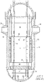
- FIG. 1 shows an exemplary reactor pressure vessel 10 and nuclear core 14.
- the nuclear core 14 includes a plurality of parallel, vertical, co-extending fuel assemblies 22.
- the other vessel internal structures can be divided into lower internals 24 and upper internals 26.
- the lower internals' function is to support, align and guide core components and instrumentation as well as direct flow within the vessel.
- the upper internals restrain or provide a secondary restraint for the fuel assemblies 22 (only two of which are shown for simplicity in FIG. 1 ), and support and guide instrumentation and components, such as control rods 28.
- FIG. 1 shows an exemplary reactor pressure vessel 10 and nuclear core 14.
- the nuclear core 14 includes a plurality of parallel, vertical, co-extending fuel assemblies 22.
- the other vessel internal structures can be divided into lower internals 24 and upper internals 26.
- the lower internals' function is to support, align and guide core components and instrumentation as well as direct flow within the vessel.
- the upper internals restrain or provide a secondary restraint for the fuel assemblies 22 (only two
- coolant enters the reactor vessel 10 through one or more inlet nozzles 30, flows down through an annulus between the vessel and the core barrel 32, is turned 180° in a lower plenum 34, passes upwardly through a lower support plate 37 and a lower core plate 36 upon which the fuel assemblies are seated and through and about the assemblies.
- the lower support plate 37 and the lower core plate 36 are replaced by a single structure, a lower core support plate having the same elevation as 37.
- the coolant flow through the core and surrounding area 38 is typically large, on the order of 1514,2 m 3 (400,000 gallons) per minute at a velocity of approximately 6,096 m (20 feet) per second.
- Coolant exiting the core 14 flows along the underside of the upper core plate 40 and upwardly through a plurality of perforations 42. The coolant then flows upwardly and radially outward to one or more outlet nozzles 44.
- Each of the fuel assemblies 22 includes fuel rods 66 grouped in an array thereof.
- the fuel rods 66 are held in spaced relationship with one another by the grids 64 spaced along the fuel assembly length.
- a bottom nozzle 58 supports each of the fuel assemblies 22 on a lower core plate 36.
- each of the fuel assemblies 22 includes a top nozzle 62.
- An instrumentation tube 68 is located in the center and extends between and is mounted to the bottom and top nozzles 58 and 62.
- Each fuel rod 66 includes a plurality of nuclear fuel pellets 70 and is closed at its opposite ends by upper and lower end plugs 72 and 74, respectively.
- the pellets 70 are maintained in a stack by a plenum spring 76 disposed between the upper end plug 72 and the top of the pellet stack.
- the fuel pellets 70 composed of fissile material, are responsible for creating the reactive power of the reactor.
- Each of the fuel rods 66 includes a cladding which surrounds the pellets to function as a barrier to prevent the fission by-products from entering the coolant and further contaminating the reactor system.
- each of the fuel rods 66 of FIG. 2 includes a stack of the plurality of nuclear fuel pellets 70, the upper and lower end plugs 72 and 74, respectively, and the spring 76 which serves as a hold-down device to maintain the stacked configuration of the pellets 70.
- FIG. 3 shows the fuel rod cladding 2 which surrounds the pellets 70 to function as a barrier to prevent the fission by-products from entering the coolant and further contaminating the reactor system.
- the cladding 2 is typically in the shape of an elongated tube having a cavity formed therein and two opposing open ends.
- the upper and lower end plugs 72 and 74, respectively, provide a seal and prevent reactor coolant that is circulating in the core from entering the cavity of the fuel rod cladding 2.
- SiC silicon carbide
- a benefit of SiC cladding is the ability to minimize a zirconium steam reaction that may occur during a severe accident and can potentially cause a dangerous hydrogen explosion.
- SiC cladding there are disadvantages associated with a SiC cladding.
- SiC cladding may exhibit surface corrosion due to exposure to coolant from a pressurized water reactor and, formation of hydro-peroxide on the SiC surface could result in severe flaking of SiC, causing significant and rapid weight loss. More particularly, SiC cladding has demonstrated difficulty in achieving hermeticity while retaining material ductility and high temperature strength. It is believed that this property conflict may be due to the need for micro-cracking, which promotes extension during straining of the SiC cladding.
- a cladding material that provides high temperature mechanical strength and stability, swelling resistance and corrosion resistance, while providing hermeticity of the SiC cladding and protection against micro-cracking and corrosion from reactor cooling during normal operation, operational transients, design basis accidents and beyond design basis accidents.
- a single material e.g., SiC
- the presence of the zirconium coating, in accordance with the invention is effective to preclude the loss of hermeticity due to micro-cracks in the ceramic composite, i.e., SiC.
- the invention provides a nuclear fuel rod cladding including a ceramic composite and a coating composition.
- the ceramic composite includes a ceramic matrix and a plurality of ceramic fibers.
- the ceramic composite is structured to form a shape that has an interior surface, an exterior surface, and an inner cavity.
- the coating composition is deposited on the exterior surface of the ceramic composite to form a coating thereon, the composition includes a zirconium component that is composed of zirconium alloy.
- the ceramic composite is in the shape of a cylindrical tube.
- the zirconium coating has a thickness from about 0.004 to about 0.006 inches.
- the ceramic composite includes a silicon carbide matrix and silicon carbide fibers.
- the silicon carbide fibers can be selected from individual fibers, woven fibers and braided fibers.
- the invention provides a method for forming a nuclear fuel rod cladding.
- the method includes preparing a ceramic composite including a ceramic matrix and ceramic fibers, forming the ceramic composite in a shape such that it has an interior surface, an exterior surface and an inner cavity, and depositing on the exterior surface of the ceramic composite a coating composition to form a coating thereon, the composition includes a zirconium component that is composed of zirconium alloy.
- preparing the ceramic composite can include obtaining ceramic fibers in a form of fiber tows; forming a woven ceramic fiber structure, wherein voids are formed therein; and depositing the ceramic matrix over the woven ceramic fiber structure to at least partially fill the voids.
- the method can include wrapping, winding or braiding the ceramic fibers.
- the method includes winding the ceramic fibers in the form of filaments over a mandrel.
- depositing the ceramic matrix can include employing a process selected from chemical vapor deposition, chemical vapor infiltration and sol gel infiltration.
- depositing the coating composition can include employing a process selected from arc spray, liquid phase spray, plasma spray, cold spray and laser deposition.
- the present invention relates generally to a coated composite material for nuclear fuel components, such as, but not limited to, fuel rod cladding, as well as methods of preparation.
- the coated composite includes a combination of ceramic and metallic components.
- the ceramic component is in the form of a ceramic composite that includes a ceramic matrix and ceramic fibers.
- the ceramic composite includes silicon carbide.
- the ceramic matrix and/or the ceramic fibers are composed of silicon carbide or silicon carbide-containing material.
- the metallic component is in the form of a coating composition and includes zirconium alloy.
- the ceramic composite is formed or shaped into the nuclear fuel component, such as, fuel rod cladding, which includes an interior surface, an exterior surface and a cavity formed therein, and the coating composition is deposited on the exterior surface of the ceramic composite, e.g., cladding, to form thereon a zirconium coating, e.g., thin film.
- the nuclear fuel component such as, fuel rod cladding
- the coating composition is deposited on the exterior surface of the ceramic composite, e.g., cladding, to form thereon a zirconium coating, e.g., thin film.
- the presence of the zirconium coating serves as an Environmental Barrier Coating (EBC) on the ceramic composite and therefore, is effective to mitigate the potential for corrosion that is generally associated with ceramic, e.g., when in contact with coolant water in a nuclear water reactor.
- EBC Environmental Barrier Coating
- the zirconium coating effectively contributes to maintaining hermeticity of the ceramic composite cladding due to micro-cracking of the ceramic, e.g., silicon carbide, matrix under various loading conditions during operation , such as, system pressure, thermal quenching, fatigue, impact during seismic/Loss of Coolant Accident (LOCA), impact during handling, and the like.
- LOCA Coolant Accident
- the zirconium coating forms a hermetic barrier for fission products and may also provide some mechanical support for the cladding structure.
- the ceramic composite can be composed of silicon carbide fibers distributed or embedded within a silicon carbide matrix, or interlocking woven or braided fibers, e.g., fiber tows wrapped to form a woven structure.
- the zirconium-coated, ceramic composite is an effective barrier to protect the contents contained within the cladding structure from exposure to high temperature environments and mechanical stresses.
- the cladding may be suitable for use as fuel cladding for containing nuclear fuel in reactor environments having liquid coolant circulating at high temperatures.
- the fuel cladding has the capability to withstand normal and accident conditions, such as, design basis accidents and beyond design basis accidents, associated with nuclear fuel reactors.
- normal and accident conditions such as, design basis accidents and beyond design basis accidents, associated with nuclear fuel reactors.
- the invention is described herein in the context of a fuel cladding for containing or holding radioactive fuel pellets, wherein the cladding is placed in a reactor core and exposed to high temperature coolant circulating around the outside of the cladding and through the core.
- the invention is not limited to this context.
- Fuel rod cladding is typically in the shape of an elongated tube having a cavity formed therein and two opposing open ends.
- the thickness of the tube wall can vary. In certain embodiments, the tube wall thickness is from about 100 to about 1000 microns.
- the cavity has fuel pellets contained therein and typically a hold-down device, such as a spring, to maintain the configuration, e.g., a stack, of the fuel pellets.
- a sealing mechanism is typically positioned at or in each open end of the cladding to provide a seal and prevent the coolant circulating in the core from entering the cavity of fuel rod cladding. (As shown in FIG. 3 .)
- the fuel rod cladding is positioned in the core of the nuclear reactor. (As shown in FIG. 2 .)
- Fuel rod cladding is primarily intended to contain fissile fuel pellets in which fission is causing heat generation and, to separate from a coolant medium the fuel pellets and fission products resulting from the fission.
- the cladding is typically composed of either a metallic material, e.g., zirconium or zirconium alloy, or alternatively a ceramic material, e.g., silicon carbide.
- metallic cladding provides good hermeticity, good ductility, adjustable strength and a protective corrosion resistant layer.
- ceramic cladding provides high stiffness, high temperature strength, high temperature survivability in oxidative and corrosive environments.
- a liner composed of metal e.g., chromium tungsten
- a cladding composed of ceramic composite e.g., silicon carbide matrix with silicon carbide fibers
- a silicon carbide monolithic layer to the surface of the metal liner, such that the metal liner is positioned between the ceramic composite and the silicon carbide monolithic layer.
- the fuel rod cladding in accordance with the invention provides a multi-component material system that combines both metal, e.g., zirconium alloy, and ceramic materials, e.g., silicon carbide matrix and fibers, such that properties and advantages associated with each of these materials can be exhibited in the cladding.
- the invention includes a ceramic composite tube and a metal composition, which consists of a zirconium alloy, deposited in the form of a coating on an outer surface of the ceramic composite tube.
- the fuel rod cladding composed of the multi-component material avoids problems associated with conventional ceramic composite systems, such as, difficulty in achieving hermeticity, while retaining material ductility and high temperature strength.
- the presence of the zirconium coating is effective to preclude the loss of hermeticity due to micro-cracks in the silicon carbide material and protection against corrosion from reactor coolant.
- FIG. 4 is a schematic, cross-section view, of a fuel rod in accordance with certain embodiments of the invention.
- the cladding 80 of the fuel rod is in the form of a cylindrical tube.
- the shape of the cladding is not limiting and can include a wide variety of shapes and configurations.
- the cladding can be in the form of a box structure or other closed form including two-dimensional axially or conically extended structures.
- the structure may be consistently shaped or inconsistently shaped; that is, the shape may be adjusted to accommodate variations in diameter along its length.
- the cylindrical tube may be used in a variety of environments, such as, but not limited to, a reactor wherein the cladding 80 has contained therein a fuel element.
- the cladding 80 includes the cylindrical tube, which, as a non-limiting example, may be a preformed cylinder, that has an inner cavity 81 and an interior surface 82.
- the cladding 80 is composed of a ceramic composite 83 and a zirconium layer 86 deposited on a surface 84 of the ceramic composite 83.
- the inner cavity 81 of the cladding 80 also includes a stack of the plurality of nuclear fuel pellets 70, the upper and lower end plugs 72 and 74, respectively, and the spring 76 which serves as a hold-down device to maintain the stacked configuration of the pellets 70.
- the cladding 80 surrounds the pellets 70 to function as a barrier to prevent the fission by-products from entering the coolant and further contaminating the reactor system.
- the upper and lower end plugs 72 and 74 respectively, provide a seal and prevent reactor coolant that is circulating in the core from entering the inner cavity 81 of the cladding 80.
- FIG. 5 is a schematic that shows a cross section of a zirconium-coated, ceramic composite cladding in more detail.
- the cladding 80 is composed of the ceramic composite 83 that includes a ceramic matrix and ceramic fibers, wherein the ceramic can include silicon carbide or a silicon-carbide-containing material.
- the zirconium layer 86 e.g., in the form of a coating, such as, a thin film, is applied to the surface 84 of the ceramic composite 83.
- the zirconium layer 86 is composed of zirconium or zirconium alloy.
- the zirconium layer 86 is exposed to and in contact with coolant that circulates in a nuclear reactor and is effective to preclude the coolant from contacting the ceramic composite 83, which is positioned underneath of the zirconium layer 86.
- the cladding 80 includes ceramic, e.g., silicon carbide/silicon carbide-containing, matrix and ceramic, e.g., silicon carbide/silicon carbide-containing, fibers. Generally, the fibers are distributed or embedded in the matrix. The fibers can include interlocking woven or braided, e.g., wound, fibers.
- the thickness of the cladding 80 can vary. For example, the cladding 80 can have a thickness in the range from about 100 to about 600 microns.
- the cladding 80 is typically formed using conventional apparatus and processes.
- the ceramic composite 83 may be constructed by prestressing a fiber component, forming fibers into tows, wrapping, wounding or braiding the fibers in a form of, for example, a cylindrical tube.
- a continuous braid lay-up (preforming) or filament winding over a mandrel can be employed.
- the ceramic matrix is applied to at least partially fill the voids formed between the fibers.
- a thin (submicron) interface layer may be incorporated between the fibers and the adjacent ceramic matrix. The presence of the interface layer allows for ductile behavior.
- the ceramic matrix can be deposited or applied by employing chemical vapor infiltration (CVI) or chemical vapor deposition (CVD) technology.
- CVI refers to depositing the ceramic matrix in pores using decomposed gaseous matrix precursors
- CVD refers to depositing the ceramic matrix on surfaces using decomposed gaseous matrix precursors.
- CVI is conducted at temperatures from about 300°C to about 1100°C depending on the particular CVI process and apparatus employed.
- Traditional decomposition-based CVI occurs from about 900°C to about 1100°C.
- atomic layer deposition-based SiC deposition is carried out at temperatures from about 300°C to about 500°C.
- a conventional sol gel infiltration, drying and firing process may be used to form the ceramic composite.
- the zirconium layer 86 provides a protective coating over the ceramic composite 83.
- This zirconium or zirconium alloy layer provides hermeticity of the ceramic composite cladding 80 and protection against corrosion from reactor coolant during normal operation, operational transients, design basis accidents and beyond design basis accidents.
- the coating thickness of the zirconium layer 86 can vary and may depend on the selection of zirconium alloy. This zirconium alloy layer will be sufficiently thick to prevent exposure of the underlying ceramic composite 83 from exposure to the coolant, taking into account operational induced effects, such as, but not limited to zirconium oxidation, grid-to-rod fretting wear, and the like, and provide a smooth surface to facilitate fuel rod insertion.
- the thickness of the zirconium layer 86 will be appropriate to prevent excessive zirconium-steam reaction during a beyond design basis accident. That is, the maximum layer thickness is determined, and limited to, a thickness that is effective to prevent excessive hydrogen reaction during a beyond design basis accident condition.
- the zirconium layer e.g., layer 86
- This thickness can correspond to design criteria for a traditional zirconium cladding design, which includes the ability to accommodate (i) 10% (5,842 ⁇ 10 -8 m) (0.0023 mils) wall thickness reduction due to grid-to-rod fretting wear and (ii) not more than 17% (9,652 ⁇ 10 -8 m) (0.0038 mils) wall thickness loss by oxidation during a Loss of Coolant Accident (LOCA).
- LOCA Loss of Coolant Accident
- this thickness can correspond to design criteria based on reduction of at least 70% of the total amount of zirconium in a typical fuel assembly having zirconium alloy cladding.
- the fuel rod cladding in accordance with the invention can reduce the amount of zirconium in a nuclear reactor core by at least 70%, resulting in a reduction of the zirconium-steam reaction in order to reduce or preclude the generation of excessive hydrogen.
- the zirconium layer e.g., layer 86
- the zirconium layer is typically formed using conventional coating apparatus and deposition processes.
- the zirconium layer 86 may be formed by employing arc spray, liquid phase spray, plasma spray, cold-spray or laser deposition for applying a coating composition and forming a coating having a thickness that is sufficiently thick to provide complete coverage of the surface of the underlying ceramic composite 83, and to retain a protective surface layer over the lifetime of the cladding.
- Preferred methods include plasma spray or laser deposition of the zirconium or zirconium alloy composition onto the ceramic composite.
- the ceramic composite e.g., both of the fibers and matrix, and the zirconium coating exhibit high strength and stiffness at both reactor normal operating temperature, and at higher temperatures that are typical of design basis and beyond design basis accidents.
- the zirconium-coated, ceramic composite fuel rod cladding in accordance with the invention provides at least one or more of the following benefits as compared to conventional claddings known in the art:
- the cladding functions include containing the fuel and fuel fission products, providing mechanical strength and stability, and providing protection and hermeticity to the external environment.
Landscapes
- Engineering & Computer Science (AREA)
- Physics & Mathematics (AREA)
- Plasma & Fusion (AREA)
- General Engineering & Computer Science (AREA)
- High Energy & Nuclear Physics (AREA)
- Metallurgy (AREA)
- Manufacturing & Machinery (AREA)
- Monitoring And Testing Of Nuclear Reactors (AREA)
- Other Surface Treatments For Metallic Materials (AREA)
- Catalysts (AREA)
Claims (12)
- Nuklearer Brennstab mit Kernbrennstab-Ummantelung (80) zur Verwendung in einem Kernreaktor mit einem darin strömenden Kühlmittel, wobei die Kernbrennstab-Ummantelung umfasst:einen Basis-Keramikverbundstoff (83), der aufgebaut ist, um eine Form zu bilden, die eine innere Oberfläche (82), eine äußere Oberfläche (84) und einen Innenhohlraum (81) aufweist, wobei der Basis-Keramikverbundstoff umfasst:eine Keramikmatrix; undeine Vielzahl von Keramikfasern;nuklearen Brennstoff, der innerhalb des inneren Hohlraum des Basis-Keramikverbundstoffs positioniert ist und mit der inneren Oberfläche des Basis-Keramikverbundstoffs in Kontakt steht; undeine Beschichtungszusammensetzung umfassend eine Zirkonium-Komponente, die aus einer Zirkoniumlegierung besteht, die auf der äußeren Oberfläche (84) des Basis-Keramikverbundstoffs (83) abgeschieden ist, um eine Beschichtung (86) darauf zu bilden, die, wenn sie in einem Kernreaktor mit einem darin strömenden Kühlmittel verwendet wird, in Kontakt mit dem Kühlmittel steht.
- Nuklearer Brennstab mit Kernbrennstab-Ummantelung (80) nach Anspruch 1, wobei die Keramikmatrix aus einem Material besteht, das aus der Gruppe ausgewählt ist, die aus Siliziumkarbid und Siliziumkarbid enthaltendem Material besteht.
- Nuklearer Brennstab mit Kernbrennstab-Ummantelung (80) nach Anspruch 1, wobei die Vielzahl von Keramikfasern aus Material besteht, das aus der Gruppe ausgewählt ist, die aus Siliziumkarbid und einem Siliziumkarbid enthaltenden Material besteht.
- Nuklearer Brennstab mit Kernbrennstab-Ummantelung (80) nach Anspruch 1, wobei die Vielzahl von Keramikfasern aus der Gruppe ausgewählt ist, die aus individuellen Fasern, verwebten Fasern und geflochtenen Fasern besteht.
- Nuklearer Brennstab mit Kernbrennstab-Ummantelung (80) nach Anspruch 1, wobei die Beschichtung (86) eine Dicke von etwa 0,1 bis etwa 0,15 cm (etwa 0,004 bis etwa 0,006 Zoll) aufweist.
- Nuklearer Brennstab mit Kernbrennstab-Ummantelung (80) nach Anspruch 1, wobei der Basis-Keramikverbundstoff (83) in der Form eines zylindrischen Rohrs vorliegt.
- Verfahren zur Herstellung eines Kernbrennstabs mit Kernbrennstab-Ummantelung (80) für einen Kernreaktor mit einem darin strömenden Kühlmittel, wobei das Verfahren umfasst:Herstellen eines Basis-Keramikverbundstoffs (83), der umfasst:eine Keramikmatrix; undeine Vielzahl von Keramikfasern;Bilden des Basis-Keramikverbundstoff (83) in einer solchen Gestalt, dass er eine innere Oberfläche (82), eine äußere Oberfläche (84) und einen Innenhohlraum (81) aufweist, wobei nuklearer Brennstoff innerhalb des Innenhohlraums des Basis-Keramikverbundstoffs (83) und in Kontakt mit der inneren Oberfläche des Basis-Keramikverbundstoffs positioniert wird; undAbscheiden einer Beschichtungszusammensetzung umfassend eine Zirkonium-Komponente, die aus einer Zirkoniumlegierung besteht, auf der äußeren Oberfläche (84) des Basis-Keramikverbundstoffs (83), um eine Beschichtung (86) darauf zu bilden, die, wenn sie in einem Kernreaktor mit einem darin strömenden Kühlmittel verwendet wird, in Kontakt mit dem Kühlmittel steht.
- Verfahren nach Anspruch 7, wobei das Herstellen des Basis-Keramikverbundstoffs (83) umfasst:Erhalten der Vielzahl von keramischen Fasern in Form von Faserwerg;Ausbilden einer gewebten keramischen Faserstruktur, wobei Hohlräume darin ausgebildet sind; undAbscheiden der Keramikmatrix auf der gewebten keramischen Faserstruktur, um die Hohlräume zumindest zum Teil zu füllen.
- Verfahren nach Anspruch 8, wobei das Ausbilden einer gewebten keramischen Faserstruktur einen Prozess einsetzt, der aus der Gruppe ausgewählt ist, die aus Umschlagen, Wickeln und Flechten besteht.
- Verfahren nach Anspruch 9, wobei der Wickelprozess das Wickeln der Keramikfasern in der Form von Filamenten um eine Spindel umfasst.
- Verfahren nach Anspruch 8, wobei das Abscheiden einer Keramikmatrix das Einsetzen eines Prozesses umfasst, der aus chemischer Gasphasen-Abscheidung, chemischer Gasphasen-Infiltration und Sol-Gel-Infiltration ausgewählt ist.
- Verfahren nach Anspruch 7, wobei das Abscheiden einer Beschichtungszusammensetzung das Einsetzen eines Prozesses umfasst, der aus Schmelzen im Lichtbogen, Flüssigphasen-Sprühen, Plasma-Sprühen, Kaltsprühen und Laserabscheidung ausgewählt ist.
Applications Claiming Priority (2)
| Application Number | Priority Date | Filing Date | Title |
|---|---|---|---|
| US15/178,745 US10872701B2 (en) | 2016-06-10 | 2016-06-10 | Zirconium-coated silicon carbide fuel cladding for accident tolerant fuel application |
| PCT/US2017/033736 WO2018044371A2 (en) | 2016-06-10 | 2017-05-22 | Zirconium-coated silicon carbide fuel cladding for accident tolerant fuel application |
Publications (3)
| Publication Number | Publication Date |
|---|---|
| EP3469595A2 EP3469595A2 (de) | 2019-04-17 |
| EP3469595A4 EP3469595A4 (de) | 2020-01-08 |
| EP3469595B1 true EP3469595B1 (de) | 2022-09-21 |
Family
ID=60574156
Family Applications (1)
| Application Number | Title | Priority Date | Filing Date |
|---|---|---|---|
| EP17847119.9A Active EP3469595B1 (de) | 2016-06-10 | 2017-05-22 | Zirconiumbeschichtete siliciumcarbidbrennstabummantelung für unfalltolerante brennstabanwendung |
Country Status (7)
| Country | Link |
|---|---|
| US (2) | US10872701B2 (de) |
| EP (1) | EP3469595B1 (de) |
| JP (1) | JP6962930B2 (de) |
| KR (1) | KR102423508B1 (de) |
| CN (1) | CN109313943A (de) |
| ES (1) | ES2932193T3 (de) |
| WO (1) | WO2018044371A2 (de) |
Families Citing this family (7)
| Publication number | Priority date | Publication date | Assignee | Title |
|---|---|---|---|---|
| US10872701B2 (en) | 2016-06-10 | 2020-12-22 | Westinghouse Electric Company Llc | Zirconium-coated silicon carbide fuel cladding for accident tolerant fuel application |
| US20200161010A1 (en) * | 2018-11-20 | 2020-05-21 | Westinghouse Electric Company Llc | Coatings and Surface Modifications to Mitigate SiC Cladding During Operation in Light Water Reactors |
| CN109627008B (zh) * | 2019-01-17 | 2021-04-30 | 苏州宏久航空防热材料科技有限公司 | 一种具有叠层复合结构材料的制备方法 |
| RU2762000C1 (ru) * | 2020-11-10 | 2021-12-14 | Акционерное общество "Высокотехнологический научно-исследовательский институт неорганических материалов имени академика А.А. Бочвара" (АО "ВНИИНМ") | Способ изготовления керамической многослойной трубки для оболочки тепловыделяющего элемента ядерной энергетической установки |
| CN114203314B (zh) * | 2021-12-06 | 2022-12-09 | 西安交通大学 | 一种液态金属填充间隙的复合碳化硅包壳核燃料棒 |
| EP4213161A1 (de) * | 2022-01-18 | 2023-07-19 | Framatome | Kernbrennelement mit einem kern aus spaltbarem material und einer verstärkungshülle und verfahren zu dessen herstellung |
| CN115524456A (zh) * | 2022-10-10 | 2022-12-27 | 中国核动力研究设计院 | 一种模拟失水事故复杂环境条件的实验装置及其实验方法 |
Family Cites Families (35)
| Publication number | Priority date | Publication date | Assignee | Title |
|---|---|---|---|---|
| US3427185A (en) * | 1964-02-19 | 1969-02-11 | United Aircraft Corp | Composite structural material incorporating metallic filaments in a matrix,and method of manufacture |
| US3615277A (en) * | 1969-05-02 | 1971-10-26 | United Aircraft Corp | Method of fabricating fiber-reinforced articles and products produced thereby |
| BE790453A (fr) * | 1971-10-26 | 1973-02-15 | Brooks Reginald G | Fabrication d'articles en metal |
| US5260137A (en) * | 1990-06-07 | 1993-11-09 | Avco Corporation | Infiltrated fiber-reinforced metallic and intermetallic alloy matrix composites |
| US5274686A (en) * | 1992-09-25 | 1993-12-28 | Combustion Engineering, Inc. | Anodic vacuum arc deposition |
| JP2913015B2 (ja) * | 1996-03-01 | 1999-06-28 | 工業技術院長 | 表面被覆方法 |
| US7236560B2 (en) | 2002-09-04 | 2007-06-26 | Koninklijke Philips Electronics N.V. | Anti-scattering X-ray shielding for CT scanners |
| US7282274B2 (en) * | 2003-11-07 | 2007-10-16 | General Electric Company | Integral composite structural material |
| US20060039524A1 (en) | 2004-06-07 | 2006-02-23 | Herbert Feinroth | Multi-layered ceramic tube for fuel containment barrier and other applications in nuclear and fossil power plants |
| CN101019193A (zh) * | 2004-06-07 | 2007-08-15 | 西屋电气有限责任公司 | 在核和化石发电厂中用于燃料安全壳屏蔽和其它应用的多层陶瓷管 |
| JP4140593B2 (ja) * | 2004-09-21 | 2008-08-27 | 住友電気工業株式会社 | メタライズ基板 |
| FR2936088B1 (fr) * | 2008-09-18 | 2011-01-07 | Commissariat Energie Atomique | Gaine de combustible nucleaire a haute conductivite thermique et son procede de fabrication. |
| US20100272982A1 (en) * | 2008-11-04 | 2010-10-28 | Graeme Dickinson | Thermal spray coatings for semiconductor applications |
| JP5443807B2 (ja) * | 2009-03-27 | 2014-03-19 | Dowaメタルテック株式会社 | 金属セラミックス接合基板及びその製造方法 |
| US9275762B2 (en) * | 2010-10-08 | 2016-03-01 | Advanced Ceramic Fibers, Llc | Cladding material, tube including such cladding material and methods of forming the same |
| US20130077731A1 (en) | 2011-03-28 | 2013-03-28 | Torxx Group Inc. | Ceramic encapsulations for nuclear materials and systems and methods of production and use |
| US20130010915A1 (en) * | 2011-07-08 | 2013-01-10 | Battelle Energy Alliance, Llc | Reactor fuel elements and related methods |
| FR2978697B1 (fr) * | 2011-08-01 | 2014-05-16 | Commissariat Energie Atomique | Tube multicouche ameliore en materiau composite a matrice ceramique, gaine de combustible nucleaire en resultant et procedes de fabrication associes |
| CN103295652B (zh) * | 2012-02-24 | 2017-02-08 | 上海核工程研究设计院 | 采用陶瓷包壳金属芯块的核燃料棒 |
| KR20130117124A (ko) * | 2012-04-17 | 2013-10-25 | 충남대학교산학협력단 | 핵연료봉 피복관용 지르코늄-세라믹 하이브리드 튜브 및 그 제조방법 |
| KR101405396B1 (ko) * | 2012-06-25 | 2014-06-10 | 한국수력원자력 주식회사 | 표면에 혼합층을 포함하는 코팅층이 형성된 지르코늄 합금 및 이의 제조방법 |
| US20150228363A1 (en) * | 2012-09-05 | 2015-08-13 | Transatomic Power Corporation | Nuclear reactors and related methods and apparatus |
| US8971476B2 (en) * | 2012-11-07 | 2015-03-03 | Westinghouse Electric Company Llc | Deposition of integrated protective material into zirconium cladding for nuclear reactors by high-velocity thermal application |
| US10128003B2 (en) | 2012-12-28 | 2018-11-13 | Terrapower, Llc | Fuel assembly |
| US9911511B2 (en) * | 2012-12-28 | 2018-03-06 | Global Nuclear Fuel—Americas, LLC | Fuel rods with wear-inhibiting coatings and methods of making the same |
| KR101486260B1 (ko) | 2013-04-17 | 2015-01-28 | 한국원자력연구원 | 금속-세라믹 하이브리드 피복관 및 그 제조방법 |
| US10060018B2 (en) * | 2013-05-28 | 2018-08-28 | Westinghouse Electric Company Llc | Kinetically applied gradated Zr-Al-C ceramic or Ti-Al-C ceramic or amorphous or semi-amorphous stainless steel with nuclear grade zirconium alloy metal structure |
| KR101526305B1 (ko) | 2013-06-19 | 2015-06-10 | 한국원자력연구원 | 다층구조 금속-세라믹 복합체 핵연료 피복관 및 이의 제조방법 |
| US9455053B2 (en) * | 2013-09-16 | 2016-09-27 | Westinghouse Electric Company Llc | SiC matrix fuel cladding tube with spark plasma sintered end plugs |
| CN104628395B (zh) * | 2013-11-07 | 2017-09-26 | 中国科学院宁波材料技术与工程研究所 | 一种核燃料包壳元件的制备方法 |
| US10102930B2 (en) * | 2013-11-13 | 2018-10-16 | Framatome Inc. | Nuclear fuel rod cladding including a metal nanomaterial layer |
| US10593434B2 (en) * | 2014-03-12 | 2020-03-17 | Westinghouse Electric Company Llc | Ceramic reinforced zirconium alloy nuclear fuel cladding with intermediate oxidation resistant layer |
| US9982350B2 (en) * | 2015-12-02 | 2018-05-29 | Westinghouse Electric Company Llc | Multilayer composite fuel clad system with high temperature hermeticity and accident tolerance |
| US10872701B2 (en) | 2016-06-10 | 2020-12-22 | Westinghouse Electric Company Llc | Zirconium-coated silicon carbide fuel cladding for accident tolerant fuel application |
| US11404175B2 (en) * | 2018-07-16 | 2022-08-02 | Westinghouse Electric Company Llc | Silicon carbide reinforced zirconium based cladding |
-
2016
- 2016-06-10 US US15/178,745 patent/US10872701B2/en not_active Expired - Fee Related
-
2017
- 2017-05-22 EP EP17847119.9A patent/EP3469595B1/de active Active
- 2017-05-22 WO PCT/US2017/033736 patent/WO2018044371A2/en not_active Ceased
- 2017-05-22 JP JP2018558285A patent/JP6962930B2/ja active Active
- 2017-05-22 ES ES17847119T patent/ES2932193T3/es active Active
- 2017-05-22 KR KR1020197000847A patent/KR102423508B1/ko active Active
- 2017-05-22 CN CN201780034630.2A patent/CN109313943A/zh active Pending
-
2020
- 2020-12-10 US US17/117,259 patent/US11862351B2/en active Active
Also Published As
| Publication number | Publication date |
|---|---|
| WO2018044371A2 (en) | 2018-03-08 |
| CN109313943A (zh) | 2019-02-05 |
| KR20190007100A (ko) | 2019-01-21 |
| WO2018044371A3 (en) | 2018-04-26 |
| US10872701B2 (en) | 2020-12-22 |
| EP3469595A2 (de) | 2019-04-17 |
| JP6962930B2 (ja) | 2021-11-05 |
| EP3469595A4 (de) | 2020-01-08 |
| US20170358372A1 (en) | 2017-12-14 |
| US20210210220A1 (en) | 2021-07-08 |
| ES2932193T3 (es) | 2023-01-16 |
| JP2019525131A (ja) | 2019-09-05 |
| KR102423508B1 (ko) | 2022-07-20 |
| US11862351B2 (en) | 2024-01-02 |
Similar Documents
| Publication | Publication Date | Title |
|---|---|---|
| US11862351B2 (en) | Zirconium-coated silicon carbide fuel cladding for accident tolerant fuel application | |
| EP3383644B1 (de) | Brennstabplattierungssystem aus mehrschichtigem verbundstoff mit hoher temperaturdichtheit und unfalltoleranz | |
| KR100877757B1 (ko) | 원자력과 화력 발전소내의 연료 격납 방호벽 및 다른 적용에 대한 다층 세라믹 관과 그에 대한 방법 | |
| EP3010024B1 (de) | Rohrkörper und verfahren zur herstellung des rohrkörpers | |
| EP3117439B1 (de) | Keramikverstärkte zirkoniumlegierungskernbrennelementverkleidung mit oxidationsbeständiger zwischenschicht | |
| RU2567874C2 (ru) | Твердая промежуточная прокладка с открытой пористостью для ядерного управляющего стержня | |
| US20160049211A1 (en) | Silicon carbide multilayered cladding and nuclear reactor fuel element for use in water-cooled nuclear power reactors | |
| KR20180031052A (ko) | 지르코늄 합금 클래딩 상의 내부식성 및 내마모성 피막 | |
| KR20250121596A (ko) | 산화 및 수소화로부터 zr 합금 클래딩을 보호하기 위한 효과적인 코팅 모폴로지 | |
| US20230368931A1 (en) | Fuel cladding covered by a mesh | |
| RU2370835C1 (ru) | Микротвэл ядерного реактора |
Legal Events
| Date | Code | Title | Description |
|---|---|---|---|
| STAA | Information on the status of an ep patent application or granted ep patent |
Free format text: STATUS: THE INTERNATIONAL PUBLICATION HAS BEEN MADE |
|
| PUAI | Public reference made under article 153(3) epc to a published international application that has entered the european phase |
Free format text: ORIGINAL CODE: 0009012 |
|
| STAA | Information on the status of an ep patent application or granted ep patent |
Free format text: STATUS: REQUEST FOR EXAMINATION WAS MADE |
|
| 17P | Request for examination filed |
Effective date: 20181022 |
|
| AK | Designated contracting states |
Kind code of ref document: A2 Designated state(s): AL AT BE BG CH CY CZ DE DK EE ES FI FR GB GR HR HU IE IS IT LI LT LU LV MC MK MT NL NO PL PT RO RS SE SI SK SM TR |
|
| AX | Request for extension of the european patent |
Extension state: BA ME |
|
| DAV | Request for validation of the european patent (deleted) | ||
| DAX | Request for extension of the european patent (deleted) | ||
| A4 | Supplementary search report drawn up and despatched |
Effective date: 20191211 |
|
| RIC1 | Information provided on ipc code assigned before grant |
Ipc: G21C 21/02 20060101ALI20191205BHEP Ipc: G21C 3/07 20060101AFI20191205BHEP Ipc: G21C 9/00 20060101ALI20191205BHEP |
|
| GRAP | Despatch of communication of intention to grant a patent |
Free format text: ORIGINAL CODE: EPIDOSNIGR1 |
|
| STAA | Information on the status of an ep patent application or granted ep patent |
Free format text: STATUS: GRANT OF PATENT IS INTENDED |
|
| INTG | Intention to grant announced |
Effective date: 20220706 |
|
| GRAS | Grant fee paid |
Free format text: ORIGINAL CODE: EPIDOSNIGR3 |
|
| GRAA | (expected) grant |
Free format text: ORIGINAL CODE: 0009210 |
|
| STAA | Information on the status of an ep patent application or granted ep patent |
Free format text: STATUS: THE PATENT HAS BEEN GRANTED |
|
| AK | Designated contracting states |
Kind code of ref document: B1 Designated state(s): AL AT BE BG CH CY CZ DE DK EE ES FI FR GB GR HR HU IE IS IT LI LT LU LV MC MK MT NL NO PL PT RO RS SE SI SK SM TR |
|
| REG | Reference to a national code |
Ref country code: GB Ref legal event code: FG4D |
|
| REG | Reference to a national code |
Ref country code: CH Ref legal event code: EP |
|
| REG | Reference to a national code |
Ref country code: IE Ref legal event code: FG4D |
|
| REG | Reference to a national code |
Ref country code: DE Ref legal event code: R096 Ref document number: 602017062039 Country of ref document: DE |
|
| REG | Reference to a national code |
Ref country code: AT Ref legal event code: REF Ref document number: 1520363 Country of ref document: AT Kind code of ref document: T Effective date: 20221015 |
|
| REG | Reference to a national code |
Ref country code: SE Ref legal event code: TRGR |
|
| REG | Reference to a national code |
Ref country code: LT Ref legal event code: MG9D |
|
| REG | Reference to a national code |
Ref country code: ES Ref legal event code: FG2A Ref document number: 2932193 Country of ref document: ES Kind code of ref document: T3 Effective date: 20230116 |
|
| REG | Reference to a national code |
Ref country code: NL Ref legal event code: MP Effective date: 20220921 |
|
| PG25 | Lapsed in a contracting state [announced via postgrant information from national office to epo] |
Ref country code: RS Free format text: LAPSE BECAUSE OF FAILURE TO SUBMIT A TRANSLATION OF THE DESCRIPTION OR TO PAY THE FEE WITHIN THE PRESCRIBED TIME-LIMIT Effective date: 20220921 Ref country code: NO Free format text: LAPSE BECAUSE OF FAILURE TO SUBMIT A TRANSLATION OF THE DESCRIPTION OR TO PAY THE FEE WITHIN THE PRESCRIBED TIME-LIMIT Effective date: 20221221 Ref country code: LV Free format text: LAPSE BECAUSE OF FAILURE TO SUBMIT A TRANSLATION OF THE DESCRIPTION OR TO PAY THE FEE WITHIN THE PRESCRIBED TIME-LIMIT Effective date: 20220921 Ref country code: LT Free format text: LAPSE BECAUSE OF FAILURE TO SUBMIT A TRANSLATION OF THE DESCRIPTION OR TO PAY THE FEE WITHIN THE PRESCRIBED TIME-LIMIT Effective date: 20220921 Ref country code: FI Free format text: LAPSE BECAUSE OF FAILURE TO SUBMIT A TRANSLATION OF THE DESCRIPTION OR TO PAY THE FEE WITHIN THE PRESCRIBED TIME-LIMIT Effective date: 20220921 |
|
| REG | Reference to a national code |
Ref country code: AT Ref legal event code: MK05 Ref document number: 1520363 Country of ref document: AT Kind code of ref document: T Effective date: 20220921 |
|
| PG25 | Lapsed in a contracting state [announced via postgrant information from national office to epo] |
Ref country code: HR Free format text: LAPSE BECAUSE OF FAILURE TO SUBMIT A TRANSLATION OF THE DESCRIPTION OR TO PAY THE FEE WITHIN THE PRESCRIBED TIME-LIMIT Effective date: 20220921 Ref country code: GR Free format text: LAPSE BECAUSE OF FAILURE TO SUBMIT A TRANSLATION OF THE DESCRIPTION OR TO PAY THE FEE WITHIN THE PRESCRIBED TIME-LIMIT Effective date: 20221222 |
|
| PG25 | Lapsed in a contracting state [announced via postgrant information from national office to epo] |
Ref country code: SM Free format text: LAPSE BECAUSE OF FAILURE TO SUBMIT A TRANSLATION OF THE DESCRIPTION OR TO PAY THE FEE WITHIN THE PRESCRIBED TIME-LIMIT Effective date: 20220921 Ref country code: RO Free format text: LAPSE BECAUSE OF FAILURE TO SUBMIT A TRANSLATION OF THE DESCRIPTION OR TO PAY THE FEE WITHIN THE PRESCRIBED TIME-LIMIT Effective date: 20220921 Ref country code: PT Free format text: LAPSE BECAUSE OF FAILURE TO SUBMIT A TRANSLATION OF THE DESCRIPTION OR TO PAY THE FEE WITHIN THE PRESCRIBED TIME-LIMIT Effective date: 20230123 Ref country code: AT Free format text: LAPSE BECAUSE OF FAILURE TO SUBMIT A TRANSLATION OF THE DESCRIPTION OR TO PAY THE FEE WITHIN THE PRESCRIBED TIME-LIMIT Effective date: 20220921 |
|
| PG25 | Lapsed in a contracting state [announced via postgrant information from national office to epo] |
Ref country code: SK Free format text: LAPSE BECAUSE OF FAILURE TO SUBMIT A TRANSLATION OF THE DESCRIPTION OR TO PAY THE FEE WITHIN THE PRESCRIBED TIME-LIMIT Effective date: 20220921 Ref country code: PL Free format text: LAPSE BECAUSE OF FAILURE TO SUBMIT A TRANSLATION OF THE DESCRIPTION OR TO PAY THE FEE WITHIN THE PRESCRIBED TIME-LIMIT Effective date: 20220921 Ref country code: IS Free format text: LAPSE BECAUSE OF FAILURE TO SUBMIT A TRANSLATION OF THE DESCRIPTION OR TO PAY THE FEE WITHIN THE PRESCRIBED TIME-LIMIT Effective date: 20230121 Ref country code: EE Free format text: LAPSE BECAUSE OF FAILURE TO SUBMIT A TRANSLATION OF THE DESCRIPTION OR TO PAY THE FEE WITHIN THE PRESCRIBED TIME-LIMIT Effective date: 20220921 |
|
| REG | Reference to a national code |
Ref country code: DE Ref legal event code: R097 Ref document number: 602017062039 Country of ref document: DE |
|
| PG25 | Lapsed in a contracting state [announced via postgrant information from national office to epo] |
Ref country code: NL Free format text: LAPSE BECAUSE OF FAILURE TO SUBMIT A TRANSLATION OF THE DESCRIPTION OR TO PAY THE FEE WITHIN THE PRESCRIBED TIME-LIMIT Effective date: 20220921 Ref country code: AL Free format text: LAPSE BECAUSE OF FAILURE TO SUBMIT A TRANSLATION OF THE DESCRIPTION OR TO PAY THE FEE WITHIN THE PRESCRIBED TIME-LIMIT Effective date: 20220921 |
|
| PLBE | No opposition filed within time limit |
Free format text: ORIGINAL CODE: 0009261 |
|
| STAA | Information on the status of an ep patent application or granted ep patent |
Free format text: STATUS: NO OPPOSITION FILED WITHIN TIME LIMIT |
|
| PG25 | Lapsed in a contracting state [announced via postgrant information from national office to epo] |
Ref country code: DK Free format text: LAPSE BECAUSE OF FAILURE TO SUBMIT A TRANSLATION OF THE DESCRIPTION OR TO PAY THE FEE WITHIN THE PRESCRIBED TIME-LIMIT Effective date: 20220921 |
|
| 26N | No opposition filed |
Effective date: 20230622 |
|
| PG25 | Lapsed in a contracting state [announced via postgrant information from national office to epo] |
Ref country code: SI Free format text: LAPSE BECAUSE OF FAILURE TO SUBMIT A TRANSLATION OF THE DESCRIPTION OR TO PAY THE FEE WITHIN THE PRESCRIBED TIME-LIMIT Effective date: 20220921 |
|
| PGFP | Annual fee paid to national office [announced via postgrant information from national office to epo] |
Ref country code: GB Payment date: 20230816 Year of fee payment: 7 Ref country code: ES Payment date: 20230907 Year of fee payment: 7 Ref country code: CZ Payment date: 20230821 Year of fee payment: 7 |
|
| PGFP | Annual fee paid to national office [announced via postgrant information from national office to epo] |
Ref country code: SE Payment date: 20230815 Year of fee payment: 7 Ref country code: FR Payment date: 20230816 Year of fee payment: 7 Ref country code: DE Payment date: 20230817 Year of fee payment: 7 |
|
| REG | Reference to a national code |
Ref country code: CH Ref legal event code: PL |
|
| PG25 | Lapsed in a contracting state [announced via postgrant information from national office to epo] |
Ref country code: MC Free format text: LAPSE BECAUSE OF FAILURE TO SUBMIT A TRANSLATION OF THE DESCRIPTION OR TO PAY THE FEE WITHIN THE PRESCRIBED TIME-LIMIT Effective date: 20220921 |
|
| REG | Reference to a national code |
Ref country code: BE Ref legal event code: MM Effective date: 20230531 |
|
| PG25 | Lapsed in a contracting state [announced via postgrant information from national office to epo] |
Ref country code: MC Free format text: LAPSE BECAUSE OF FAILURE TO SUBMIT A TRANSLATION OF THE DESCRIPTION OR TO PAY THE FEE WITHIN THE PRESCRIBED TIME-LIMIT Effective date: 20220921 Ref country code: LU Free format text: LAPSE BECAUSE OF NON-PAYMENT OF DUE FEES Effective date: 20230522 Ref country code: LI Free format text: LAPSE BECAUSE OF NON-PAYMENT OF DUE FEES Effective date: 20230531 Ref country code: CH Free format text: LAPSE BECAUSE OF NON-PAYMENT OF DUE FEES Effective date: 20230531 |
|
| REG | Reference to a national code |
Ref country code: IE Ref legal event code: MM4A |
|
| PG25 | Lapsed in a contracting state [announced via postgrant information from national office to epo] |
Ref country code: IE Free format text: LAPSE BECAUSE OF NON-PAYMENT OF DUE FEES Effective date: 20230522 |
|
| PG25 | Lapsed in a contracting state [announced via postgrant information from national office to epo] |
Ref country code: IE Free format text: LAPSE BECAUSE OF NON-PAYMENT OF DUE FEES Effective date: 20230522 |
|
| PG25 | Lapsed in a contracting state [announced via postgrant information from national office to epo] |
Ref country code: IT Free format text: LAPSE BECAUSE OF FAILURE TO SUBMIT A TRANSLATION OF THE DESCRIPTION OR TO PAY THE FEE WITHIN THE PRESCRIBED TIME-LIMIT Effective date: 20220921 Ref country code: BE Free format text: LAPSE BECAUSE OF NON-PAYMENT OF DUE FEES Effective date: 20230531 |
|
| PG25 | Lapsed in a contracting state [announced via postgrant information from national office to epo] |
Ref country code: BG Free format text: LAPSE BECAUSE OF FAILURE TO SUBMIT A TRANSLATION OF THE DESCRIPTION OR TO PAY THE FEE WITHIN THE PRESCRIBED TIME-LIMIT Effective date: 20220921 |
|
| PG25 | Lapsed in a contracting state [announced via postgrant information from national office to epo] |
Ref country code: BG Free format text: LAPSE BECAUSE OF FAILURE TO SUBMIT A TRANSLATION OF THE DESCRIPTION OR TO PAY THE FEE WITHIN THE PRESCRIBED TIME-LIMIT Effective date: 20220921 |
|
| REG | Reference to a national code |
Ref country code: DE Ref legal event code: R119 Ref document number: 602017062039 Country of ref document: DE |
|
| REG | Reference to a national code |
Ref country code: SE Ref legal event code: EUG |
|
| PG25 | Lapsed in a contracting state [announced via postgrant information from national office to epo] |
Ref country code: CZ Free format text: LAPSE BECAUSE OF NON-PAYMENT OF DUE FEES Effective date: 20240522 |
|
| GBPC | Gb: european patent ceased through non-payment of renewal fee |
Effective date: 20240522 |
|
| PG25 | Lapsed in a contracting state [announced via postgrant information from national office to epo] |
Ref country code: CZ Free format text: LAPSE BECAUSE OF NON-PAYMENT OF DUE FEES Effective date: 20240522 |
|
| PG25 | Lapsed in a contracting state [announced via postgrant information from national office to epo] |
Ref country code: DE Free format text: LAPSE BECAUSE OF NON-PAYMENT OF DUE FEES Effective date: 20241203 |
|
| PG25 | Lapsed in a contracting state [announced via postgrant information from national office to epo] |
Ref country code: FR Free format text: LAPSE BECAUSE OF NON-PAYMENT OF DUE FEES Effective date: 20240531 |
|
| PG25 | Lapsed in a contracting state [announced via postgrant information from national office to epo] |
Ref country code: GB Free format text: LAPSE BECAUSE OF NON-PAYMENT OF DUE FEES Effective date: 20240522 |
|
| REG | Reference to a national code |
Ref country code: ES Ref legal event code: FD2A Effective date: 20250702 |
|
| PG25 | Lapsed in a contracting state [announced via postgrant information from national office to epo] |
Ref country code: ES Free format text: LAPSE BECAUSE OF NON-PAYMENT OF DUE FEES Effective date: 20240523 |
|
| PG25 | Lapsed in a contracting state [announced via postgrant information from national office to epo] |
Ref country code: CY Free format text: LAPSE BECAUSE OF FAILURE TO SUBMIT A TRANSLATION OF THE DESCRIPTION OR TO PAY THE FEE WITHIN THE PRESCRIBED TIME-LIMIT; INVALID AB INITIO Effective date: 20170522 |
|
| PG25 | Lapsed in a contracting state [announced via postgrant information from national office to epo] |
Ref country code: HU Free format text: LAPSE BECAUSE OF FAILURE TO SUBMIT A TRANSLATION OF THE DESCRIPTION OR TO PAY THE FEE WITHIN THE PRESCRIBED TIME-LIMIT; INVALID AB INITIO Effective date: 20170522 |
|
| PG25 | Lapsed in a contracting state [announced via postgrant information from national office to epo] |
Ref country code: SE Free format text: LAPSE BECAUSE OF NON-PAYMENT OF DUE FEES Effective date: 20240523 |
|
| PG25 | Lapsed in a contracting state [announced via postgrant information from national office to epo] |
Ref country code: TR Free format text: LAPSE BECAUSE OF FAILURE TO SUBMIT A TRANSLATION OF THE DESCRIPTION OR TO PAY THE FEE WITHIN THE PRESCRIBED TIME-LIMIT Effective date: 20220921 |