EP3469314B1 - Capteur de champ magnétique pour détecter la proximité et/ou l'emplacement d'un objet - Google Patents
Capteur de champ magnétique pour détecter la proximité et/ou l'emplacement d'un objet Download PDFInfo
- Publication number
- EP3469314B1 EP3469314B1 EP17726478.5A EP17726478A EP3469314B1 EP 3469314 B1 EP3469314 B1 EP 3469314B1 EP 17726478 A EP17726478 A EP 17726478A EP 3469314 B1 EP3469314 B1 EP 3469314B1
- Authority
- EP
- European Patent Office
- Prior art keywords
- magnetic field
- substrate
- field sensing
- sensing element
- field sensor
- Prior art date
- Legal status (The legal status is an assumption and is not a legal conclusion. Google has not performed a legal analysis and makes no representation as to the accuracy of the status listed.)
- Active
Links
- 230000005291 magnetic effect Effects 0.000 title claims description 297
- 239000000758 substrate Substances 0.000 claims description 190
- 230000005355 Hall effect Effects 0.000 claims description 114
- 230000005294 ferromagnetic effect Effects 0.000 claims description 114
- 239000004065 semiconductor Substances 0.000 claims description 32
- 230000035945 sensitivity Effects 0.000 claims description 22
- 230000008859 change Effects 0.000 claims description 13
- 230000033001 locomotion Effects 0.000 claims description 10
- 230000000295 complement effect Effects 0.000 claims 4
- 230000004044 response Effects 0.000 description 20
- 238000013459 approach Methods 0.000 description 11
- 238000010586 diagram Methods 0.000 description 11
- 230000008878 coupling Effects 0.000 description 8
- 238000010168 coupling process Methods 0.000 description 8
- 238000005859 coupling reaction Methods 0.000 description 8
- 230000006870 function Effects 0.000 description 8
- 238000009987 spinning Methods 0.000 description 6
- CWYNVVGOOAEACU-UHFFFAOYSA-N Fe2+ Chemical compound [Fe+2] CWYNVVGOOAEACU-UHFFFAOYSA-N 0.000 description 4
- 230000004807 localization Effects 0.000 description 4
- 238000004519 manufacturing process Methods 0.000 description 4
- 238000000034 method Methods 0.000 description 4
- 238000000926 separation method Methods 0.000 description 4
- 230000004907 flux Effects 0.000 description 2
- WPYVAWXEWQSOGY-UHFFFAOYSA-N indium antimonide Chemical compound [Sb]#[In] WPYVAWXEWQSOGY-UHFFFAOYSA-N 0.000 description 2
- 239000000463 material Substances 0.000 description 2
- 229910052751 metal Inorganic materials 0.000 description 2
- 239000002184 metal Substances 0.000 description 2
- JBRZTFJDHDCESZ-UHFFFAOYSA-N AsGa Chemical compound [As]#[Ga] JBRZTFJDHDCESZ-UHFFFAOYSA-N 0.000 description 1
- XUIMIQQOPSSXEZ-UHFFFAOYSA-N Silicon Chemical compound [Si] XUIMIQQOPSSXEZ-UHFFFAOYSA-N 0.000 description 1
- 230000004888 barrier function Effects 0.000 description 1
- 230000015572 biosynthetic process Effects 0.000 description 1
- 239000003990 capacitor Substances 0.000 description 1
- 238000006243 chemical reaction Methods 0.000 description 1
- 150000001875 compounds Chemical class 0.000 description 1
- 239000004020 conductor Substances 0.000 description 1
- 238000009792 diffusion process Methods 0.000 description 1
- -1 e.g. Chemical compound 0.000 description 1
- 230000000694 effects Effects 0.000 description 1
- 230000005684 electric field Effects 0.000 description 1
- 229910052732 germanium Inorganic materials 0.000 description 1
- GNPVGFCGXDBREM-UHFFFAOYSA-N germanium atom Chemical compound [Ge] GNPVGFCGXDBREM-UHFFFAOYSA-N 0.000 description 1
- 239000007943 implant Substances 0.000 description 1
- 150000002472 indium compounds Chemical class 0.000 description 1
- 230000001939 inductive effect Effects 0.000 description 1
- 230000005381 magnetic domain Effects 0.000 description 1
- 230000000306 recurrent effect Effects 0.000 description 1
- 229910052710 silicon Inorganic materials 0.000 description 1
- 239000010703 silicon Substances 0.000 description 1
- 230000005641 tunneling Effects 0.000 description 1
Images


Classifications
-
- G—PHYSICS
- G01—MEASURING; TESTING
- G01D—MEASURING NOT SPECIALLY ADAPTED FOR A SPECIFIC VARIABLE; ARRANGEMENTS FOR MEASURING TWO OR MORE VARIABLES NOT COVERED IN A SINGLE OTHER SUBCLASS; TARIFF METERING APPARATUS; MEASURING OR TESTING NOT OTHERWISE PROVIDED FOR
- G01D5/00—Mechanical means for transferring the output of a sensing member; Means for converting the output of a sensing member to another variable where the form or nature of the sensing member does not constrain the means for converting; Transducers not specially adapted for a specific variable
- G01D5/12—Mechanical means for transferring the output of a sensing member; Means for converting the output of a sensing member to another variable where the form or nature of the sensing member does not constrain the means for converting; Transducers not specially adapted for a specific variable using electric or magnetic means
- G01D5/14—Mechanical means for transferring the output of a sensing member; Means for converting the output of a sensing member to another variable where the form or nature of the sensing member does not constrain the means for converting; Transducers not specially adapted for a specific variable using electric or magnetic means influencing the magnitude of a current or voltage
- G01D5/142—Mechanical means for transferring the output of a sensing member; Means for converting the output of a sensing member to another variable where the form or nature of the sensing member does not constrain the means for converting; Transducers not specially adapted for a specific variable using electric or magnetic means influencing the magnitude of a current or voltage using Hall-effect devices
-
- G—PHYSICS
- G01—MEASURING; TESTING
- G01P—MEASURING LINEAR OR ANGULAR SPEED, ACCELERATION, DECELERATION, OR SHOCK; INDICATING PRESENCE, ABSENCE, OR DIRECTION, OF MOVEMENT
- G01P3/00—Measuring linear or angular speed; Measuring differences of linear or angular speeds
- G01P3/42—Devices characterised by the use of electric or magnetic means
- G01P3/44—Devices characterised by the use of electric or magnetic means for measuring angular speed
- G01P3/48—Devices characterised by the use of electric or magnetic means for measuring angular speed by measuring frequency of generated current or voltage
- G01P3/481—Devices characterised by the use of electric or magnetic means for measuring angular speed by measuring frequency of generated current or voltage of pulse signals
- G01P3/488—Devices characterised by the use of electric or magnetic means for measuring angular speed by measuring frequency of generated current or voltage of pulse signals delivered by variable reluctance detectors
-
- G—PHYSICS
- G01—MEASURING; TESTING
- G01B—MEASURING LENGTH, THICKNESS OR SIMILAR LINEAR DIMENSIONS; MEASURING ANGLES; MEASURING AREAS; MEASURING IRREGULARITIES OF SURFACES OR CONTOURS
- G01B7/00—Measuring arrangements characterised by the use of electric or magnetic techniques
- G01B7/02—Measuring arrangements characterised by the use of electric or magnetic techniques for measuring length, width or thickness
- G01B7/023—Measuring arrangements characterised by the use of electric or magnetic techniques for measuring length, width or thickness for measuring distance between sensor and object
-
- G—PHYSICS
- G01—MEASURING; TESTING
- G01D—MEASURING NOT SPECIALLY ADAPTED FOR A SPECIFIC VARIABLE; ARRANGEMENTS FOR MEASURING TWO OR MORE VARIABLES NOT COVERED IN A SINGLE OTHER SUBCLASS; TARIFF METERING APPARATUS; MEASURING OR TESTING NOT OTHERWISE PROVIDED FOR
- G01D5/00—Mechanical means for transferring the output of a sensing member; Means for converting the output of a sensing member to another variable where the form or nature of the sensing member does not constrain the means for converting; Transducers not specially adapted for a specific variable
- G01D5/12—Mechanical means for transferring the output of a sensing member; Means for converting the output of a sensing member to another variable where the form or nature of the sensing member does not constrain the means for converting; Transducers not specially adapted for a specific variable using electric or magnetic means
- G01D5/14—Mechanical means for transferring the output of a sensing member; Means for converting the output of a sensing member to another variable where the form or nature of the sensing member does not constrain the means for converting; Transducers not specially adapted for a specific variable using electric or magnetic means influencing the magnitude of a current or voltage
- G01D5/142—Mechanical means for transferring the output of a sensing member; Means for converting the output of a sensing member to another variable where the form or nature of the sensing member does not constrain the means for converting; Transducers not specially adapted for a specific variable using electric or magnetic means influencing the magnitude of a current or voltage using Hall-effect devices
- G01D5/147—Mechanical means for transferring the output of a sensing member; Means for converting the output of a sensing member to another variable where the form or nature of the sensing member does not constrain the means for converting; Transducers not specially adapted for a specific variable using electric or magnetic means influencing the magnitude of a current or voltage using Hall-effect devices influenced by the movement of a third element, the position of Hall device and the source of magnetic field being fixed in respect to each other
-
- G—PHYSICS
- G01—MEASURING; TESTING
- G01D—MEASURING NOT SPECIALLY ADAPTED FOR A SPECIFIC VARIABLE; ARRANGEMENTS FOR MEASURING TWO OR MORE VARIABLES NOT COVERED IN A SINGLE OTHER SUBCLASS; TARIFF METERING APPARATUS; MEASURING OR TESTING NOT OTHERWISE PROVIDED FOR
- G01D5/00—Mechanical means for transferring the output of a sensing member; Means for converting the output of a sensing member to another variable where the form or nature of the sensing member does not constrain the means for converting; Transducers not specially adapted for a specific variable
- G01D5/12—Mechanical means for transferring the output of a sensing member; Means for converting the output of a sensing member to another variable where the form or nature of the sensing member does not constrain the means for converting; Transducers not specially adapted for a specific variable using electric or magnetic means
- G01D5/14—Mechanical means for transferring the output of a sensing member; Means for converting the output of a sensing member to another variable where the form or nature of the sensing member does not constrain the means for converting; Transducers not specially adapted for a specific variable using electric or magnetic means influencing the magnitude of a current or voltage
- G01D5/16—Mechanical means for transferring the output of a sensing member; Means for converting the output of a sensing member to another variable where the form or nature of the sensing member does not constrain the means for converting; Transducers not specially adapted for a specific variable using electric or magnetic means influencing the magnitude of a current or voltage by varying resistance
Claims (24)
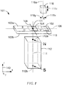
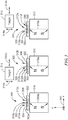
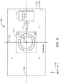
- Capteur de champ magnétique pour détecter un mouvement d'un objet ferromagnétique (116) le long d'une trajectoire, le capteur de champ magnétique comprenant :un aimant (112) ;un substrat semiconducteur (102) situé près de l'aimant (112) et à une position entre l'objet ferromagnétique (116) et l'aimant (112), le substrat semiconducteur (102) comprenant :des premier et second axes de substrat (106, 108) sur une surface du substrat semiconducteur (102), qui se coupent au niveau d'un point d'axes de substrat de manière à diviser le substrat semiconducteur en quatre parties planes dans un plan des axes de substrat, le premier axe de substrat (106) divisant le plan des axes de substrat en une première paire de demi-plans complémentaires sur des côtés opposés du premier axe de substrat (106) et le second axe de substrat (108) divisant le plan des axes de substrat en une seconde paire de demi-plans complémentaires sur des côtés opposés du second axe de substrat (108) ; etune région de substrat (104) sur la surface du substrat semiconducteur (102), la région de substrat (104) étant près du point d'axes de substrat et entourant celui-ci, des champs magnétiques générés par l'aimant (112) au niveau de la région de substrat (104) étant sensiblement perpendiculaires au substrat semiconducteur (102) en l'absence de l'objet ferromagnétique (116), le capteur de champ magnétique comprenant en outre :un premier élément de détection de champ magnétique (204) disposé sur ou sous la surface du substrat semiconducteur (102) et disposé à l'intérieur de la région de substrat (104), le premier élément de détection de champ magnétique (204) comprenant un axe de sensibilité maximale sensiblement parallèle au premier axe de substrat (106), un centre du premier élément de détection de champ magnétique (204) étant disposé sur le second axe de substrat (108) ; etun circuit électronique (110) disposé sur ou sous la surface du substrat semiconducteur (102), couplé au premier élément de détection de champ magnétique (204) et configuré pour générer, sur la base de la magnitude et du signe d'un signal de sortie de l'élément de détection de champ magnétique, un signal de position ayant une pluralité d'états, l'état du signal de position indiquant si l'objet ferromagnétique (116) est plus près ou plus loin qu'une distance prédéterminée du capteur de champ magnétique et, si l'objet ferromagnétique est plus près que la distance prédéterminée, l'état indiquant en outre si l'objet ferromagnétique (116) est plus près des parties planes du substrat se trouvant dans un premier demi-plan de la seconde paire de demi-plans complémentaires ou est plus près des parties planes se trouvant dans un second demi-plan de la seconde paire de demi-plans complémentaires.
- Capteur de champ magnétique selon la revendication 1, dans lequel le circuit électronique (110) est en outre configuré pour générer un signal de comparaison à deux états ayant un changement d'état quand l'objet ferromagnétique (116) se déplace plus près du substrat semiconducteur (102) qu'une distance prédéterminée.
- Capteur de champ magnétique selon la revendication 1, dans lequel le premier élément de détection de champ magnétique (204) comprend un élément à effet Hall vertical.
- Capteur de champ magnétique selon la revendication 1, dans lequel le premier élément de détection de champ magnétique (204) comprend un élément à magnétorésistance.
- Capteur de champ magnétique selon la revendication 1, comprenant en outre :
un deuxième élément de détection de champ magnétique disposé sur ou sous la surface du substrat semiconducteur (102) et disposé à l'intérieur de la région de substrat, le deuxième élément de détection de champ magnétique comprenant un axe de sensibilité maximale sensiblement parallèle à l'axe de sensibilité maximale du premier élément de détection de champ magnétique. - Capteur de champ magnétique selon la revendication 5, dans lequel un centre du deuxième élément de détection de champ magnétique est disposé sur le second axe de substrat (108) et pas sur le point d'axes de substrat.
- Capteur de champ magnétique selon la revendication 6, dans lequel les centres des premier et deuxième éléments de détection de champ magnétique sont sensiblement équidistants du point d'axes de substrat et sur des côtés opposés du point d'axes de substrat.
- Capteur de champ magnétique selon la revendication 5, dans lequel le circuit électronique (110) est également couplé au deuxième élément de détection de champ magnétique, et dans lequel le circuit électronique est en outre configuré pour générer un signal de comparaison à deux états ayant un changement d'état quand l'objet ferromagnétique (116) se déplace plus près du substrat semiconducteur (102) que la distance prédéterminée.
- Capteur de champ magnétique selon la revendication 5, dans lequel le circuit électronique (110) est également couplé au deuxième élément de détection de champ magnétique.
- Capteur de champ magnétique selon la revendication 5, comprenant en outre :un troisième élément de détection de champ magnétique disposé sur ou sous la surface du substrat semiconducteur (102) et disposé à l'intérieur de la région de substrat, le troisième élément de détection de champ magnétique comprenant un axe de sensibilité maximale non parallèle à l'axe de sensibilité maximale du premier élément de détection de champ magnétique ; etun quatrième élément de détection de champ magnétique disposé sur ou sous la surface du substrat semiconducteur et disposé à l'intérieur de la région de substrat, le quatrième élément de détection de champ magnétique comprenant un axe de sensibilité maximale non parallèle à l'axe de sensibilité maximale du premier élément de détection de champ magnétique.
- Capteur de champ magnétique selon la revendication 10, dans lequel le centre du premier élément de détection de champ magnétique (204) est disposé sur le second axe de substrat (108), dans lequel un centre du deuxième élément de détection de champ magnétique est disposé sur le second axe de substrat, dans lequel un centre du troisième élément de détection de champ magnétique est disposé sur le premier axe de substrat et pas sur le point d'axes de substrat, et dans lequel un centre du quatrième élément de détection de champ magnétique est disposé sur le premier axe de substrat et pas sur le point d'axes de substrat.
- Capteur de champ magnétique selon la revendication 11, dans lequel les centres des premier et deuxième éléments de détection de champ magnétique sont sensiblement équidistants du point d'axes de substrat et sur des côtés opposés du point d'axes de substrat, et dans lequel les centres des troisième et quatrième éléments de détection de champ magnétique sont sensiblement équidistants du point d'axes de substrat et sur des côtés opposés du point d'axes de substrat.
- Capteur de champ magnétique selon la revendication 10, dans lequel les premier, deuxième, troisième et quatrième éléments de détection de champ magnétique sont des éléments à effet Hall vertical à l'intérieur d'un élément de détection à effet Hall vertical circulaire (CVH).
- Capteur de champ magnétique selon la revendication 10, dans lequel le circuit électronique (110) est également couplé aux troisième et quatrième éléments de détection de champ magnétique et configuré pour générer un signal de comparaison à deux états ayant un changement d'état sélectionné quand l'objet ferromagnétique (116) se déplace plus près du substrat semiconducteur (102) que la distance prédéterminée.
- Capteur de champ magnétique selon la revendication 10, dans lequel le circuit électronique (110) est en outre couplé aux deuxième, troisième et quatrième éléments de détection de champ magnétique, et dans lequel chaque état indique en outre de quelle partie plane respective des quatre parties planes l'objet ferromagnétique (116) est la plus près.
- Capteur de champ magnétique selon la revendication 10, dans lequel les premier, deuxième, troisième et quatrième éléments de détection de champ magnétique comprennent des éléments à effet Hall vertical.
- Capteur de champ magnétique selon la revendication 10, dans lequel les premier, deuxième, troisième et quatrième éléments de détection de champ magnétique comprennent des éléments à magnétorésistance.
- Capteur de champ magnétique selon la revendication 1, comprenant en outre :
un deuxième élément de détection de champ magnétique disposé sur ou sous la surface du substrat semiconducteur (102) et disposé à l'intérieur de la région de substrat, le deuxième élément de détection de champ magnétique comprenant un axe de sensibilité maximale sensiblement perpendiculaire à l'axe de sensibilité maximale du premier élément de détection de champ magnétique. - Capteur de champ magnétique selon la revendication 18, dans lequel un centre du deuxième élément de détection de champ magnétique est disposé sur le premier axe de substrat (106), et dans lequel les centres des premier et deuxième éléments de détection de champ magnétique sont sensiblement équidistants du point d'axes de substrat et pas sur le point d'axes de substrat.
- Capteur de champ magnétique selon la revendication 18, dans lequel le circuit électronique (110) est également couplé au deuxième élément de détection de champ magnétique, et dans lequel le circuit électronique est en outre configuré pour générer un signal de comparaison à deux états ayant un changement d'état quand l'objet ferromagnétique (116) se déplace plus près du substrat semiconducteur (102) que la distance prédéterminée.
- Capteur de champ magnétique selon la revendication 18, dans lequel le circuit électronique (110) est également couplé au deuxième élément de détection de champ magnétique, et dans lequel chaque état indique en outre de quelle partie plane respective des quatre parties planes l'objet ferromagnétique (116) est la plus près.
- Capteur de champ magnétique selon la revendication 5 ou 18, dans lequel les premier et deuxième éléments de détection de champ magnétique comprennent des éléments à effet Hall vertical.
- Capteur de champ magnétique selon la revendication 5 ou 18, dans lequel les premier et deuxième éléments de détection de champ magnétique comprennent des éléments à magnétorésistance.
- Capteur de champ magnétique selon la revendication 1, 5 ou 10, dans lequel le signal de position comprend un signal numérique.
Applications Claiming Priority (2)
| Application Number | Priority Date | Filing Date | Title |
|---|---|---|---|
| US15/176,668 US10215590B2 (en) | 2016-06-08 | 2016-06-08 | Magnetic field sensor for sensing a proximity and/or a location of an object |
| PCT/US2017/033530 WO2017213824A1 (fr) | 2016-06-08 | 2017-05-19 | Capteur de champ magnétique pour détecter la proximité et/ou l'emplacement d'un objet |
Publications (2)
| Publication Number | Publication Date |
|---|---|
| EP3469314A1 EP3469314A1 (fr) | 2019-04-17 |
| EP3469314B1 true EP3469314B1 (fr) | 2021-04-07 |
Family
ID=58794223
Family Applications (1)
| Application Number | Title | Priority Date | Filing Date |
|---|---|---|---|
| EP17726478.5A Active EP3469314B1 (fr) | 2016-06-08 | 2017-05-19 | Capteur de champ magnétique pour détecter la proximité et/ou l'emplacement d'un objet |
Country Status (3)
| Country | Link |
|---|---|
| US (1) | US10215590B2 (fr) |
| EP (1) | EP3469314B1 (fr) |
| WO (1) | WO2017213824A1 (fr) |
Families Citing this family (12)
| Publication number | Priority date | Publication date | Assignee | Title |
|---|---|---|---|---|
| US9810519B2 (en) | 2013-07-19 | 2017-11-07 | Allegro Microsystems, Llc | Arrangements for magnetic field sensors that act as tooth detectors |
| US9823092B2 (en) | 2014-10-31 | 2017-11-21 | Allegro Microsystems, Llc | Magnetic field sensor providing a movement detector |
| US10866117B2 (en) * | 2018-03-01 | 2020-12-15 | Allegro Microsystems, Llc | Magnetic field influence during rotation movement of magnetic target |
| DE102018112398A1 (de) * | 2018-05-23 | 2019-11-28 | Guboa Technology Co., Ltd | Vorrichtung zur Erfassung einer linearen Verschiebung |
| DE102018210595A1 (de) * | 2018-06-28 | 2020-01-02 | Infineon Technologies Ag | Sensorvorrichtungen und Verfahren zur Herstellung von Sensorvorrichtungen |
| US11255700B2 (en) | 2018-08-06 | 2022-02-22 | Allegro Microsystems, Llc | Magnetic field sensor |
| US10837753B2 (en) | 2019-01-10 | 2020-11-17 | Allegro Microsystems, Llc | Magnetic field sensor using MR elements for detecting flux line divergence |
| JP7260321B2 (ja) * | 2019-02-15 | 2023-04-18 | エイブリック株式会社 | 磁気センサ回路 |
| US11385075B2 (en) | 2020-02-21 | 2022-07-12 | Allegro Microsystems, Llc | Orientation independent magnetic field sensor |
| US11608109B2 (en) * | 2020-08-12 | 2023-03-21 | Analog Devices International Unlimited Company | Systems and methods for detecting magnetic turn counter errors with redundancy |
| US11733316B2 (en) * | 2020-12-14 | 2023-08-22 | Allegro Microsystems, Llc | Position sensor having harmonic distortion compensation |
| US11630168B2 (en) | 2021-02-03 | 2023-04-18 | Allegro Microsystems, Llc | Linear sensor with dual spin valve element having reference layers with magnetization directions different from an external magnetic field direction |
Family Cites Families (33)
| Publication number | Priority date | Publication date | Assignee | Title |
|---|---|---|---|---|
| JPS5613244B2 (fr) | 1974-07-31 | 1981-03-27 | ||
| DE3122376A1 (de) | 1981-06-05 | 1982-12-23 | Robert Bosch Gmbh, 7000 Stuttgart | Vorrichtung zur erfassung der drehzahl von rotierenden teilen |
| US5045920A (en) * | 1990-06-28 | 1991-09-03 | Allegro Microsystems, Inc. | Dual-Hall ferrous-article-proximity sensor |
| US5304926A (en) | 1992-04-08 | 1994-04-19 | Honeywell Inc. | Geartooth position sensor with two hall effect elements |
| US5341097A (en) | 1992-09-29 | 1994-08-23 | Honeywell Inc. | Asymmetrical magnetic position detector |
| WO1997006404A2 (fr) | 1995-08-02 | 1997-02-20 | Durakool Inc | Capteur de mouvement de dent de roue, a definition et stabilite ameliorees |
| US6525531B2 (en) | 1996-01-17 | 2003-02-25 | Allegro, Microsystems, Inc. | Detection of passing magnetic articles while adapting the detection threshold |
| US5896030A (en) | 1996-10-09 | 1999-04-20 | Honeywell Inc. | Magnetic sensor with components attached to transparent plate for laser trimming during calibration |
| US6278269B1 (en) | 1999-03-08 | 2001-08-21 | Allegro Microsystems, Inc. | Magnet structure |
| JP2002372416A (ja) * | 2001-04-09 | 2002-12-26 | Nagano Fujitsu Component Kk | センサユニット |
| JP4855603B2 (ja) * | 2001-08-01 | 2012-01-18 | 富士通コンポーネント株式会社 | 加速度検出装置 |
| DE10210184A1 (de) | 2002-03-07 | 2003-09-18 | Philips Intellectual Property | Anordnung zum Bestimmen der Position eines Bewegungsgeberelements |
| US7199579B2 (en) | 2004-03-08 | 2007-04-03 | Allegro Microsystems, Inc. | Proximity detector |
| WO2005088259A1 (fr) | 2004-03-11 | 2005-09-22 | Robert Bosch Gmbh | Systeme de capteurs magnetiques |
| DE102004017191B4 (de) | 2004-04-07 | 2007-07-12 | Infineon Technologies Ag | Vorrichtung und Verfahren zur Ermittlung einer Richtung eines Objekts |
| US7365530B2 (en) | 2004-04-08 | 2008-04-29 | Allegro Microsystems, Inc. | Method and apparatus for vibration detection |
| US7112957B2 (en) * | 2004-06-16 | 2006-09-26 | Honeywell International Inc. | GMR sensor with flux concentrators |
| US7253614B2 (en) | 2005-03-21 | 2007-08-07 | Allegro Microsystems, Inc. | Proximity detector having a sequential flow state machine |
| US7915886B2 (en) * | 2007-01-29 | 2011-03-29 | Honeywell International Inc. | Magnetic speed, direction, and/or movement extent sensor |
| EP2000813A1 (fr) | 2007-05-29 | 2008-12-10 | Ecole Polytechnique Fédérale de Lausanne | Transducteur de champ magnétique pour capter l'orientation d'un champ magnétique dans un plan |
| DE102007041230B3 (de) * | 2007-08-31 | 2009-04-09 | Fraunhofer-Gesellschaft zur Förderung der angewandten Forschung e.V. | Kalibrierbarer mehrdimensionaler magnetischer Punktsensor sowie entsprechendes Verfahren und Computerprogramm dafür |
| JP5324388B2 (ja) | 2009-10-15 | 2013-10-23 | 株式会社東海理化電機製作所 | 近接センサ |
| US8729892B2 (en) * | 2011-04-01 | 2014-05-20 | Allegro Microsystems, Llc | Differential magnetic field sensor structure for orientation independent measurement |
| US8729890B2 (en) | 2011-04-12 | 2014-05-20 | Allegro Microsystems, Llc | Magnetic angle and rotation speed sensor with continuous and discontinuous modes of operation based on rotation speed of a target object |
| US9575120B2 (en) | 2013-03-29 | 2017-02-21 | International Business Machines Corporation | Scan chain processing in a partially functional chip |
| WO2014189733A1 (fr) | 2013-05-24 | 2014-11-27 | Allegro Microsystems, Llc | Capteur de champ magnétique destiné à détecter un champ magnétique dans une direction quelconque au-dessus de seuils |
| US9733106B2 (en) | 2013-05-24 | 2017-08-15 | Allegro Microsystems, Llc | Magnetic field sensor to detect a magnitude of a magnetic field in any direction |
| US9982989B2 (en) * | 2013-07-17 | 2018-05-29 | Infineon Technologies Ag | Angle sensors, systems and methods |
| DE202014004425U1 (de) | 2014-04-28 | 2014-09-12 | Infineon Technologies Ag | Halleffekt-Sensoranordnung |
| US9852832B2 (en) * | 2014-06-25 | 2017-12-26 | Allegro Microsystems, Llc | Magnetic field sensor and associated method that can sense a position of a magnet |
| DE102014010547B4 (de) | 2014-07-14 | 2023-06-07 | Albert-Ludwigs-Universität Freiburg | Hallsensor |
| US9719806B2 (en) | 2014-10-31 | 2017-08-01 | Allegro Microsystems, Llc | Magnetic field sensor for sensing a movement of a ferromagnetic target object |
| US9823092B2 (en) | 2014-10-31 | 2017-11-21 | Allegro Microsystems, Llc | Magnetic field sensor providing a movement detector |
-
2016
- 2016-06-08 US US15/176,668 patent/US10215590B2/en active Active
-
2017
- 2017-05-19 EP EP17726478.5A patent/EP3469314B1/fr active Active
- 2017-05-19 WO PCT/US2017/033530 patent/WO2017213824A1/fr unknown
Non-Patent Citations (1)
| Title |
|---|
| None * |
Also Published As
| Publication number | Publication date |
|---|---|
| WO2017213824A1 (fr) | 2017-12-14 |
| US20170356762A1 (en) | 2017-12-14 |
| EP3469314A1 (fr) | 2019-04-17 |
| US10215590B2 (en) | 2019-02-26 |
Similar Documents
| Publication | Publication Date | Title |
|---|---|---|
| EP3469314B1 (fr) | Capteur de champ magnétique pour détecter la proximité et/ou l'emplacement d'un objet | |
| US10837800B2 (en) | Arrangements for magnetic field sensors that act as movement detectors | |
| KR102176106B1 (ko) | 물체의 이동을 감지하는 센서 및 물체의 이동을 감지하는 방법 | |
| US9880026B1 (en) | Magnetic field sensor for detecting motion of an object | |
| EP3469313B1 (fr) | Capteur de champ magnétique pour détecter une proximité d'un objet | |
| EP3623765B1 (fr) | Capteur de champ magnétique angulaire et cible rotative avec immunité contre les champs parasites | |
| US11313700B2 (en) | Magnetic field influence during rotation movement of magnetic target | |
| EP3469315B1 (fr) | Agencements pour des capteurs de champ magnétique permettant de supprimer des variations du décalage | |
| US10670425B2 (en) | System for measuring angular position and method of stray field cancellation | |
| EP3457155B1 (fr) | Capteur de champ magnétique robuste aux champs magnétiques parasites et système associé | |
| US11215681B2 (en) | Magnetic field sensor with stray field immunity and large air gap performance | |
| CN114096807A (zh) | 具有减少的外部杂散磁场影响的磁场传感器 | |
| US10837753B2 (en) | Magnetic field sensor using MR elements for detecting flux line divergence | |
| US20190173002A1 (en) | Two-dimensional magnetic field sensor with a single integrated magnetic field concentrator | |
| US9816838B2 (en) | Magnetoresistive angle sensor with linear sensor elements | |
| US20220397382A1 (en) | Angle sensor |
Legal Events
| Date | Code | Title | Description |
|---|---|---|---|
| STAA | Information on the status of an ep patent application or granted ep patent |
Free format text: STATUS: UNKNOWN |
|
| STAA | Information on the status of an ep patent application or granted ep patent |
Free format text: STATUS: THE INTERNATIONAL PUBLICATION HAS BEEN MADE |
|
| PUAI | Public reference made under article 153(3) epc to a published international application that has entered the european phase |
Free format text: ORIGINAL CODE: 0009012 |
|
| STAA | Information on the status of an ep patent application or granted ep patent |
Free format text: STATUS: REQUEST FOR EXAMINATION WAS MADE |
|
| 17P | Request for examination filed |
Effective date: 20190107 |
|
| AK | Designated contracting states |
Kind code of ref document: A1 Designated state(s): AL AT BE BG CH CY CZ DE DK EE ES FI FR GB GR HR HU IE IS IT LI LT LU LV MC MK MT NL NO PL PT RO RS SE SI SK SM TR |
|
| AX | Request for extension of the european patent |
Extension state: BA ME |
|
| DAV | Request for validation of the european patent (deleted) | ||
| DAX | Request for extension of the european patent (deleted) | ||
| STAA | Information on the status of an ep patent application or granted ep patent |
Free format text: STATUS: EXAMINATION IS IN PROGRESS |
|
| 17Q | First examination report despatched |
Effective date: 20191009 |
|
| GRAP | Despatch of communication of intention to grant a patent |
Free format text: ORIGINAL CODE: EPIDOSNIGR1 |
|
| STAA | Information on the status of an ep patent application or granted ep patent |
Free format text: STATUS: GRANT OF PATENT IS INTENDED |
|
| INTG | Intention to grant announced |
Effective date: 20201104 |
|
| GRAS | Grant fee paid |
Free format text: ORIGINAL CODE: EPIDOSNIGR3 |
|
| GRAA | (expected) grant |
Free format text: ORIGINAL CODE: 0009210 |
|
| STAA | Information on the status of an ep patent application or granted ep patent |
Free format text: STATUS: THE PATENT HAS BEEN GRANTED |
|
| AK | Designated contracting states |
Kind code of ref document: B1 Designated state(s): AL AT BE BG CH CY CZ DE DK EE ES FI FR GB GR HR HU IE IS IT LI LT LU LV MC MK MT NL NO PL PT RO RS SE SI SK SM TR |
|
| REG | Reference to a national code |
Ref country code: GB Ref legal event code: FG4D |
|
| REG | Reference to a national code |
Ref country code: AT Ref legal event code: REF Ref document number: 1380264 Country of ref document: AT Kind code of ref document: T Effective date: 20210415 Ref country code: CH Ref legal event code: EP |
|
| REG | Reference to a national code |
Ref country code: DE Ref legal event code: R096 Ref document number: 602017036163 Country of ref document: DE |
|
| REG | Reference to a national code |
Ref country code: IE Ref legal event code: FG4D |
|
| REG | Reference to a national code |
Ref country code: LT Ref legal event code: MG9D |
|
| REG | Reference to a national code |
Ref country code: NL Ref legal event code: MP Effective date: 20210407 Ref country code: AT Ref legal event code: MK05 Ref document number: 1380264 Country of ref document: AT Kind code of ref document: T Effective date: 20210407 |
|
| PG25 | Lapsed in a contracting state [announced via postgrant information from national office to epo] |
Ref country code: LT Free format text: LAPSE BECAUSE OF FAILURE TO SUBMIT A TRANSLATION OF THE DESCRIPTION OR TO PAY THE FEE WITHIN THE PRESCRIBED TIME-LIMIT Effective date: 20210407 Ref country code: FI Free format text: LAPSE BECAUSE OF FAILURE TO SUBMIT A TRANSLATION OF THE DESCRIPTION OR TO PAY THE FEE WITHIN THE PRESCRIBED TIME-LIMIT Effective date: 20210407 Ref country code: BG Free format text: LAPSE BECAUSE OF FAILURE TO SUBMIT A TRANSLATION OF THE DESCRIPTION OR TO PAY THE FEE WITHIN THE PRESCRIBED TIME-LIMIT Effective date: 20210707 Ref country code: AT Free format text: LAPSE BECAUSE OF FAILURE TO SUBMIT A TRANSLATION OF THE DESCRIPTION OR TO PAY THE FEE WITHIN THE PRESCRIBED TIME-LIMIT Effective date: 20210407 Ref country code: HR Free format text: LAPSE BECAUSE OF FAILURE TO SUBMIT A TRANSLATION OF THE DESCRIPTION OR TO PAY THE FEE WITHIN THE PRESCRIBED TIME-LIMIT Effective date: 20210407 Ref country code: NL Free format text: LAPSE BECAUSE OF FAILURE TO SUBMIT A TRANSLATION OF THE DESCRIPTION OR TO PAY THE FEE WITHIN THE PRESCRIBED TIME-LIMIT Effective date: 20210407 |
|
| PG25 | Lapsed in a contracting state [announced via postgrant information from national office to epo] |
Ref country code: GR Free format text: LAPSE BECAUSE OF FAILURE TO SUBMIT A TRANSLATION OF THE DESCRIPTION OR TO PAY THE FEE WITHIN THE PRESCRIBED TIME-LIMIT Effective date: 20210708 Ref country code: IS Free format text: LAPSE BECAUSE OF FAILURE TO SUBMIT A TRANSLATION OF THE DESCRIPTION OR TO PAY THE FEE WITHIN THE PRESCRIBED TIME-LIMIT Effective date: 20210807 Ref country code: LV Free format text: LAPSE BECAUSE OF FAILURE TO SUBMIT A TRANSLATION OF THE DESCRIPTION OR TO PAY THE FEE WITHIN THE PRESCRIBED TIME-LIMIT Effective date: 20210407 Ref country code: SE Free format text: LAPSE BECAUSE OF FAILURE TO SUBMIT A TRANSLATION OF THE DESCRIPTION OR TO PAY THE FEE WITHIN THE PRESCRIBED TIME-LIMIT Effective date: 20210407 Ref country code: RS Free format text: LAPSE BECAUSE OF FAILURE TO SUBMIT A TRANSLATION OF THE DESCRIPTION OR TO PAY THE FEE WITHIN THE PRESCRIBED TIME-LIMIT Effective date: 20210407 Ref country code: PT Free format text: LAPSE BECAUSE OF FAILURE TO SUBMIT A TRANSLATION OF THE DESCRIPTION OR TO PAY THE FEE WITHIN THE PRESCRIBED TIME-LIMIT Effective date: 20210809 Ref country code: NO Free format text: LAPSE BECAUSE OF FAILURE TO SUBMIT A TRANSLATION OF THE DESCRIPTION OR TO PAY THE FEE WITHIN THE PRESCRIBED TIME-LIMIT Effective date: 20210707 Ref country code: PL Free format text: LAPSE BECAUSE OF FAILURE TO SUBMIT A TRANSLATION OF THE DESCRIPTION OR TO PAY THE FEE WITHIN THE PRESCRIBED TIME-LIMIT Effective date: 20210407 |
|
| REG | Reference to a national code |
Ref country code: CH Ref legal event code: PL |
|
| REG | Reference to a national code |
Ref country code: DE Ref legal event code: R097 Ref document number: 602017036163 Country of ref document: DE |
|
| PG25 | Lapsed in a contracting state [announced via postgrant information from national office to epo] |
Ref country code: SK Free format text: LAPSE BECAUSE OF FAILURE TO SUBMIT A TRANSLATION OF THE DESCRIPTION OR TO PAY THE FEE WITHIN THE PRESCRIBED TIME-LIMIT Effective date: 20210407 Ref country code: SM Free format text: LAPSE BECAUSE OF FAILURE TO SUBMIT A TRANSLATION OF THE DESCRIPTION OR TO PAY THE FEE WITHIN THE PRESCRIBED TIME-LIMIT Effective date: 20210407 Ref country code: ES Free format text: LAPSE BECAUSE OF FAILURE TO SUBMIT A TRANSLATION OF THE DESCRIPTION OR TO PAY THE FEE WITHIN THE PRESCRIBED TIME-LIMIT Effective date: 20210407 Ref country code: RO Free format text: LAPSE BECAUSE OF FAILURE TO SUBMIT A TRANSLATION OF THE DESCRIPTION OR TO PAY THE FEE WITHIN THE PRESCRIBED TIME-LIMIT Effective date: 20210407 Ref country code: LI Free format text: LAPSE BECAUSE OF NON-PAYMENT OF DUE FEES Effective date: 20210531 Ref country code: MC Free format text: LAPSE BECAUSE OF FAILURE TO SUBMIT A TRANSLATION OF THE DESCRIPTION OR TO PAY THE FEE WITHIN THE PRESCRIBED TIME-LIMIT Effective date: 20210407 Ref country code: LU Free format text: LAPSE BECAUSE OF NON-PAYMENT OF DUE FEES Effective date: 20210519 Ref country code: CH Free format text: LAPSE BECAUSE OF NON-PAYMENT OF DUE FEES Effective date: 20210531 Ref country code: DK Free format text: LAPSE BECAUSE OF FAILURE TO SUBMIT A TRANSLATION OF THE DESCRIPTION OR TO PAY THE FEE WITHIN THE PRESCRIBED TIME-LIMIT Effective date: 20210407 Ref country code: EE Free format text: LAPSE BECAUSE OF FAILURE TO SUBMIT A TRANSLATION OF THE DESCRIPTION OR TO PAY THE FEE WITHIN THE PRESCRIBED TIME-LIMIT Effective date: 20210407 Ref country code: CZ Free format text: LAPSE BECAUSE OF FAILURE TO SUBMIT A TRANSLATION OF THE DESCRIPTION OR TO PAY THE FEE WITHIN THE PRESCRIBED TIME-LIMIT Effective date: 20210407 |
|
| REG | Reference to a national code |
Ref country code: BE Ref legal event code: MM Effective date: 20210531 |
|
| PLBE | No opposition filed within time limit |
Free format text: ORIGINAL CODE: 0009261 |
|
| STAA | Information on the status of an ep patent application or granted ep patent |
Free format text: STATUS: NO OPPOSITION FILED WITHIN TIME LIMIT |
|
| 26N | No opposition filed |
Effective date: 20220110 |
|
| GBPC | Gb: european patent ceased through non-payment of renewal fee |
Effective date: 20210707 |
|
| PG25 | Lapsed in a contracting state [announced via postgrant information from national office to epo] |
Ref country code: IE Free format text: LAPSE BECAUSE OF NON-PAYMENT OF DUE FEES Effective date: 20210519 Ref country code: GB Free format text: LAPSE BECAUSE OF NON-PAYMENT OF DUE FEES Effective date: 20210707 |
|
| PG25 | Lapsed in a contracting state [announced via postgrant information from national office to epo] |
Ref country code: IS Free format text: LAPSE BECAUSE OF FAILURE TO SUBMIT A TRANSLATION OF THE DESCRIPTION OR TO PAY THE FEE WITHIN THE PRESCRIBED TIME-LIMIT Effective date: 20210807 Ref country code: FR Free format text: LAPSE BECAUSE OF NON-PAYMENT OF DUE FEES Effective date: 20210607 Ref country code: AL Free format text: LAPSE BECAUSE OF FAILURE TO SUBMIT A TRANSLATION OF THE DESCRIPTION OR TO PAY THE FEE WITHIN THE PRESCRIBED TIME-LIMIT Effective date: 20210407 |
|
| PG25 | Lapsed in a contracting state [announced via postgrant information from national office to epo] |
Ref country code: IT Free format text: LAPSE BECAUSE OF FAILURE TO SUBMIT A TRANSLATION OF THE DESCRIPTION OR TO PAY THE FEE WITHIN THE PRESCRIBED TIME-LIMIT Effective date: 20210407 Ref country code: BE Free format text: LAPSE BECAUSE OF NON-PAYMENT OF DUE FEES Effective date: 20210531 |
|
| PG25 | Lapsed in a contracting state [announced via postgrant information from national office to epo] |
Ref country code: CY Free format text: LAPSE BECAUSE OF FAILURE TO SUBMIT A TRANSLATION OF THE DESCRIPTION OR TO PAY THE FEE WITHIN THE PRESCRIBED TIME-LIMIT Effective date: 20210407 |
|
| PG25 | Lapsed in a contracting state [announced via postgrant information from national office to epo] |
Ref country code: HU Free format text: LAPSE BECAUSE OF FAILURE TO SUBMIT A TRANSLATION OF THE DESCRIPTION OR TO PAY THE FEE WITHIN THE PRESCRIBED TIME-LIMIT; INVALID AB INITIO Effective date: 20170519 |
|
| PGFP | Annual fee paid to national office [announced via postgrant information from national office to epo] |
Ref country code: DE Payment date: 20230321 Year of fee payment: 7 |
|
| PG25 | Lapsed in a contracting state [announced via postgrant information from national office to epo] |
Ref country code: MK Free format text: LAPSE BECAUSE OF FAILURE TO SUBMIT A TRANSLATION OF THE DESCRIPTION OR TO PAY THE FEE WITHIN THE PRESCRIBED TIME-LIMIT Effective date: 20210407 |