EP3469290B1 - Vorrichtung zur zentrierung in einem rohr - Google Patents
Vorrichtung zur zentrierung in einem rohr Download PDFInfo
- Publication number
- EP3469290B1 EP3469290B1 EP17735201.0A EP17735201A EP3469290B1 EP 3469290 B1 EP3469290 B1 EP 3469290B1 EP 17735201 A EP17735201 A EP 17735201A EP 3469290 B1 EP3469290 B1 EP 3469290B1
- Authority
- EP
- European Patent Office
- Prior art keywords
- fluid
- devices
- central body
- positioning
- volume
- Prior art date
- Legal status (The legal status is an assumption and is not a legal conclusion. Google has not performed a legal analysis and makes no representation as to the accuracy of the status listed.)
- Active
Links
Images



Classifications
-
- F—MECHANICAL ENGINEERING; LIGHTING; HEATING; WEAPONS; BLASTING
- F28—HEAT EXCHANGE IN GENERAL
- F28D—HEAT-EXCHANGE APPARATUS, NOT PROVIDED FOR IN ANOTHER SUBCLASS, IN WHICH THE HEAT-EXCHANGE MEDIA DO NOT COME INTO DIRECT CONTACT
- F28D20/00—Heat storage plants or apparatus in general; Regenerative heat-exchange apparatus not covered by groups F28D17/00 or F28D19/00
- F28D20/02—Heat storage plants or apparatus in general; Regenerative heat-exchange apparatus not covered by groups F28D17/00 or F28D19/00 using latent heat
- F28D20/023—Heat storage plants or apparatus in general; Regenerative heat-exchange apparatus not covered by groups F28D17/00 or F28D19/00 using latent heat the latent heat storage material being enclosed in granular particles or dispersed in a porous, fibrous or cellular structure
-
- F—MECHANICAL ENGINEERING; LIGHTING; HEATING; WEAPONS; BLASTING
- F28—HEAT EXCHANGE IN GENERAL
- F28D—HEAT-EXCHANGE APPARATUS, NOT PROVIDED FOR IN ANOTHER SUBCLASS, IN WHICH THE HEAT-EXCHANGE MEDIA DO NOT COME INTO DIRECT CONTACT
- F28D20/00—Heat storage plants or apparatus in general; Regenerative heat-exchange apparatus not covered by groups F28D17/00 or F28D19/00
- F28D2020/0004—Particular heat storage apparatus
- F28D2020/0013—Particular heat storage apparatus the heat storage material being enclosed in elements attached to or integral with heat exchange conduits
-
- F—MECHANICAL ENGINEERING; LIGHTING; HEATING; WEAPONS; BLASTING
- F28—HEAT EXCHANGE IN GENERAL
- F28D—HEAT-EXCHANGE APPARATUS, NOT PROVIDED FOR IN ANOTHER SUBCLASS, IN WHICH THE HEAT-EXCHANGE MEDIA DO NOT COME INTO DIRECT CONTACT
- F28D20/00—Heat storage plants or apparatus in general; Regenerative heat-exchange apparatus not covered by groups F28D17/00 or F28D19/00
- F28D2020/0004—Particular heat storage apparatus
- F28D2020/0021—Particular heat storage apparatus the heat storage material being enclosed in loose or stacked elements
-
- Y—GENERAL TAGGING OF NEW TECHNOLOGICAL DEVELOPMENTS; GENERAL TAGGING OF CROSS-SECTIONAL TECHNOLOGIES SPANNING OVER SEVERAL SECTIONS OF THE IPC; TECHNICAL SUBJECTS COVERED BY FORMER USPC CROSS-REFERENCE ART COLLECTIONS [XRACs] AND DIGESTS
- Y02—TECHNOLOGIES OR APPLICATIONS FOR MITIGATION OR ADAPTATION AGAINST CLIMATE CHANGE
- Y02E—REDUCTION OF GREENHOUSE GAS [GHG] EMISSIONS, RELATED TO ENERGY GENERATION, TRANSMISSION OR DISTRIBUTION
- Y02E60/00—Enabling technologies; Technologies with a potential or indirect contribution to GHG emissions mitigation
- Y02E60/14—Thermal energy storage
Definitions
- the present invention relates to the field of thermal management.
- the engine oil is very hot when the propellant engine has been running for a while. It can then be useful to store part of this thermal energy. On the other hand, when starting the engine from cold, warming the engine oil would be useful for engine performance and limit pollutant emissions.
- an assembly is provided for circulation and heat exchange with a said fluid according to claim 1, in which the duct is locally separated into several branches in which the fluid circulates in parallel.
- conduit considered may in particular be a hose or one of the many flexible pipes which run through a vehicle.
- each exchange device to promote a large volume of thermal energy storage material, it is proposed that said devices define a string of such devices following each other in the volume and from which the positioning structures of the central body will then come. in contact with the wall of the duct.
- a positioning structure comprising an outer structure defining a ring and linked by transverse arms to the central body.
- An advantage will be to be able to reduce the interval between two central bodies of two adjacent or successive devices in the volume, since the positioning structure will then extend only (substantially) in a plane. Outside this plane, two adjacent devices may succeed each other, in contact.
- the positioning structure with a diameter of about 2cm is linked to a central body of about 1cm in diameter by about fifteen rectilinear rods having a section of filamentary dimension (therefore of the order of mm) and that the discontinuous sphere is also produced by rectilinear but curved rods, it is possible to combine strength, energy performance and respect for circulation without excess pressure drop.
- the central body will appear as a sphere or will be profiled.
- the sphere is omnidirectional.
- the latter will a priori be radially distant from the central body. This is typically favorable in a conduit where the transverse arms will just provide a radial mechanical connection with the central body with little resistance to the circulation of the fluid.
- each central body can then appear as a sphere, to be easy to use and to distribute, with a minimum of dead space.
- the device produced could be a one-piece molding integrating the positioning structure and the central body therefore containing the thermal energy storage material.
- this material will favorably include at least one MCP (phase change material) allowing high energy performance.
- the positioning structure will include an outer structure defining a cylinder and linked by arms transverse to the central body, the external structures of the devices.
- said devices used will have the second function of serving as a channeling wall, instead of the duct wall, via their successive external structures.
- phase change material - or MCP PCM in English - denotes a material capable of changing physical state, for example between liquid and solid, in a temperature range of for example between -50 ° C and 180 ° C.
- the heat transfer takes place by using its Latent Heat: the material can then store or give up energy by a simple change of state, while maintaining a substantially constant temperature, that of the change of state.
- the thermally insulating material (s) associated with the MCP may (have) be a "simple" insulator such as glass wool, but we will certainly prefer a foam, for example polyurethane or polyisocyanurate.
- the positioning structure 11 will favorably ensure an axial centering of the central body 5 in the volume, when it is a positioning in a duct 15, therefore in a tubular means. .
- the positioning structure 11 will reserve the passages 13 between it and the central body 5, transversely or radially to the general axis 15a of the duct 15. And it is through this positioning structure 11 that the contact of the device 1 with the wall 31 of duct 15.
- the positioning structure 11 comprises an outer structure 17 defining (substantially or globally) a cylinder, to be oriented along the axis 15a, and linked by transverse arms 19 to the central body 5.
- the body 5 is presented here as a sphere. But it can be shaped like a shell, to further limit the pressure losses, with a volume reserved for the material 7 which can remain identical.
- the cylinder 17 may not be full, but formed by branches or lines defining such a cylindrical envelope, but with passages through to lighten it.
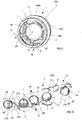
- the positioning structure 11 comprises an outer structure 170 defining a ring and linked again by transverse or radial arms 19 to the central body 5.
- the positioning structure 11 comprises an outer structure 270 defining a discontinuous sphere and linked by transverse or radial arms 190 to the central body 5 containing the material 7.
- the first and third examples are self-centering solutions in a duct, or even in a volume 3 which would be formed by the hollow interior 21 of a housing.
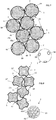
- FIG. 5 there is shown a part of another duct 23 (such as a hose) with a wall 31 still having an inlet and an outlet for the fluid 9 (arrows) and here containing a multitude of devices 1 in accordance with those of the third example.
- duct there could be several devices 1 in front, touching each other; the fluid circulating through successive passages 13.
- the material 7 may consist of at least one MCP.
- MCP encapsulated typically microencapsulated
- a porous matrix with open pores, preferably of the elastomer type, such as based on silicone, NBR or HNBR.
- elastomer type such as based on silicone, NBR or HNBR.
- a rubber composition as described in EP2690137 or in EP2690141 .
- the material 7 could also be based on paraffin, eutectic fatty acid (myristic-capric) or hydrated eutectic salt (calcium chloride + potassium). Other possibilities still exist for each body 5, such as an MCP impregnated in a porous network.
- any MCP can have a change of phase or state at a predetermined temperature peak or which is established over a more or less wide temperature range.
- a pure MCP such as a paraffin
- the change of state temperature will be constant, while it may be non-constant with several MCP, such as for a mixture of paraffins.
- the flexible link 27 may include three filamentary strands passing through three orifices (such as the one marked 29) each formed in an arm 19, near the ring 170 in question.
- the solid wall 31 which defines the duct 15 is surrounded by a thermal insulator 33 which will promote thermal management at the location of this duct, with the devices 1 arranged therein. It could be the same in the case of the figure 5 where devices 1 are not all in line behind each other.
- each device 1 is in the form of several beads 35 surrounding the central body 5 containing the material 7 for storing thermal energy by accumulating latent heat.
- the beads 35 can define at least two bands which intersect to maintain through them a free space 37 between several devices 1, each having here a spherical shape, so that, placed in the hollow interior 21, these shapes 1 are there. accumulate in the highest possible number, without loss of space, while allowing the fluid 9 to circulate in heat exchange between them.
- the free spaces 37 will be found between the devices 1 placed in the hollow interior 21, each having here a generally spherical shape.
- the recesses 39 will form blind cavities, for example each in a portion of a sphere.
- the central body 5 will extend to the bottom of said hollows and cells, or even between them.
- the alveolar structure 41 will also be open to the outside.
- the central body 5 may therefore be a porous matrix, with pores. open, for example of the elastomer type.
- FIG. 7 also schematizes in dotted lines an alternative to the recesses 39, namely orifices 40 completely passing through the body 5, the lips 40a of these orifices which open out onto the outside (and which extend around the central body, locally) having little risk to be blocked by a solid wall part of another device 1, here spherical.
- the orifices 40 will define the aforementioned passages through which the surrounding fluid passes.
- FIG. 9 Yet another exemplary embodiment is shown schematically figure 9 .
- conduit 150 for circulating the fluid 9 comprises, and in fact integrates, a string of several devices 1 arranged in series, therefore with its outer structures 11 which are each solid to each define a portion of the wall 310 of the conduit and are linked between them in a fluid-tight manner.
- the devices 1 of the chain follow one another axially (axis 15a). This is individually the solution of the figure 1 , with the outer structure which defines a cylinder oriented along the axis 15a, and linked by transverse arms 19 to the central body 5. These cylinder sections each form a portion of the cylindrical wall 310 of the duct 150.
- each device 1 may have two cylindrical end pieces 110a, 110b connected axially by an intermediate part 110c which, although substantially or generally cylindrical, will be convex towards the outside or the inside to form an axial stopper. vis-à-vis the inter-engagement with either adjacent devices 1, or tubular connectors 43 interposed axially between two devices 1 successive and defining like them (with the structures 11), a portion of the generally cylindrical wall 310 of the duct 150.
- said generally cylindrical wall 310 could be surrounded by another wall 45, thin, flexible, of flexible plastic material to which the wall 310 will give its shape.
Landscapes
- Engineering & Computer Science (AREA)
- Chemical & Material Sciences (AREA)
- Dispersion Chemistry (AREA)
- Physics & Mathematics (AREA)
- Thermal Sciences (AREA)
- Mechanical Engineering (AREA)
- General Engineering & Computer Science (AREA)
- Heat-Exchange Devices With Radiators And Conduit Assemblies (AREA)
- Thermotherapy And Cooling Therapy Devices (AREA)
- Physical Or Chemical Processes And Apparatus (AREA)
- Central Heating Systems (AREA)
Claims (15)
- Anordnung für die Zirkulation und den Wärmeaustausch mit einem Fluid (9), wobei die Anordnung enthält:- eine Leitung (15) mit einem Innenraum (3) zur Zirkulation des Fluids, in welchem das Fluid zwischen einem Einlass und einem Auslass zirkulieren kann, wobei die Leitung eine Wand (31) aufweist,- mehrere Wärmeaustausch- und Positionierungsvorrichtungen (1) in dem Raum (3), wobei jede Vorrichtung in der Leitung angeordnet ist, die von ihrer Wand (31) umgeben ist und ein Material (7) zur Speicherung von Wärmeenergie durch Akkumulation latenter Wärme enthält, das in Wärmeaustausch mit einem zirkulierenden umgebenden Fluid (9) zu bringen ist, wobei mindestens einige der Wärmeaustauschvorrichtungen (1) mit der Wand (31) der Leitung (15) in Kontakt gelangen können,dadurch gekennzeichnet, dass jede Vorrichtung (1) enthält:- einen zentralen Körper (5), der das Material (7) zur Speicherung von Wärmeenergie durch Akkumulation latenter Wärme enthält, und- eine Struktur (11; 35, 39, 41) zur Positionierung des zentralen Körpers in dem Raum (3), wobei die Positionierungsstruktur mit dem zentralen Körper, um den herum sie sich erstreckt, verbunden ist und dabei-- Durchgänge (13, 37, 40) freilässt, die einen Kontakt zwischen dem zentralen Körper (5) und dem Fluid (9) ermöglichen,-- und einen Abstand sicherstellt, der die Zirkulation des Fluids zwischen den Vorrichtungen ermöglicht.
- Anordnung für die Zirkulation und den Wärmeaustausch mit einem Fluid nach Anspruch 1,
wobei die Leitung bereichsweise in mehrere Leitungszweige (31a, 31b) unterteilt ist, in denen das Fluid parallel zirkuliert, wobei die Vorrichtungen in den von ihrer Wand umgebenen Leitungszweigen angeordnet sind. - Anordnung nach Anspruch 1 oder 2,
wobei es sich bei der Leitung (15) um einen Zufuhrschlauch oder einen der Schläuche handelt, die durch ein Fahrzeug verlaufen. - Anordnung nach einem der Ansprüche 1 bis 3,
wobei die Wärmeaustausch- und Positionierungsvorrichtungen (1) in dem Raum (3) einen Strang solcher Vorrichtungen (1) definieren, die in dem Raum (3) aufeinanderfolgen und deren Positionierungsstrukturen (11) zum Positionieren des zentralen Körpers mit der Wand (31) in Kontakt gelangen. - Anordnung nach einem der vorangehenden Ansprüche,
wobei die bzw. jede Positionierungsstruktur (11) eine äußere Struktur (17) aufweist, die einen Zylinder (17) definiert und über quer verlaufende Arme (19) mit dem zentralen Körper (5) verbunden ist. - Anordnung nach Anspruch 5,
wobei die äußeren Strukturen (17) jeweils voll ausgeführt sind, um jeweils einen Wandabschnitt (310) der Leitung zu definieren, und fluiddicht miteinander verbunden sind. - Anordnung nach einem der Ansprüche 1 bis 4,
wobei die Positionierungsstruktur (11) eine äußere Struktur (170) aufweist, die einen Ring definiert und über quer verlaufende Arme (19) mit dem zentralen Körper (5) verbunden ist. - Anordnung nach einem der Ansprüche 1 bis 4,
wobei die Positionierungsstruktur (11) eine äußere Struktur (270) aufweist, die:- eine nicht kontinuierliche Kugel (13) definiert,- und über quer verlaufende Arme (190) mit dem zentralen Körper (5) verbunden ist. - Anordnung nach einem der Ansprüche 1 bis 4,
wobei die Positionierungsstruktur (11) in Form einer Wabenstruktur (41) vorliegt, die den zentralen Körper (5) umgibt und in Kontakt mit diesem steht. - Anordnung nach einem der Ansprüche 1 bis 4,
wobei die Positionierungsstruktur (11) in Form einer oder mehrerer linearer Wülste (35), die den zentralen Körper (5) umgeben und in Kontakt mit diesem stehen, oder in Form von Vertiefungen (39), die in dem Körper ausgebildet sind, vorliegt. - Anordnung nach Anspruch 3 allein oder in Kombination mit einem der Ansprüche 4 bis 10,
wobei die Vorrichtungen (1) in einer Reihe hintereinanderliegen. - Anordnung nach einem der vorangehenden Ansprüche,
wobei es sich um ein einteiliges Formteil zwischen der Positionierungsstruktur (11) und dem zentralen Körper (5) handelt, welches das Material (7) zur Speicherung von Wärmeenergie enthält. - Anordnung nach einem der vorangehenden Ansprüche,
wobei mehrere Vorrichtungen (1) durch ein nachgiebiges Verbindungsglied (27) zu einem Strang miteinander verbunden sind. - Fahrzeug mit einer Anordnung nach Anspruch 3 allein oder in Kombination mit einem der Ansprüche 4 bis 12.
- Verfahren zum Wärmemanagement in einer Anordnung nach Anspruch 1, wobei
ein Fluid (9) in dem Raum (3) entlang der Leitung (15) in aufeinanderfolgenden Wärmeaustauschvorgängen mit den Materialien (7) zur Speicherung von Wärmeenergie der aufeinanderfolgenden zentralen Körper (5) zirkuliert.
Applications Claiming Priority (2)
| Application Number | Priority Date | Filing Date | Title |
|---|---|---|---|
| FR1655391A FR3052547B1 (fr) | 2016-06-10 | 2016-06-10 | Dispositif de centrage dans un volume |
| PCT/FR2017/051483 WO2017212199A1 (fr) | 2016-06-10 | 2017-06-09 | Dispositif de centrage dans un conduit |
Publications (2)
| Publication Number | Publication Date |
|---|---|
| EP3469290A1 EP3469290A1 (de) | 2019-04-17 |
| EP3469290B1 true EP3469290B1 (de) | 2020-12-30 |
Family
ID=56855622
Family Applications (2)
| Application Number | Title | Priority Date | Filing Date |
|---|---|---|---|
| EP17735204.4A Active EP3469291B1 (de) | 2016-06-10 | 2017-06-09 | Positioniervorrichtung in einem volumen |
| EP17735201.0A Active EP3469290B1 (de) | 2016-06-10 | 2017-06-09 | Vorrichtung zur zentrierung in einem rohr |
Family Applications Before (1)
| Application Number | Title | Priority Date | Filing Date |
|---|---|---|---|
| EP17735204.4A Active EP3469291B1 (de) | 2016-06-10 | 2017-06-09 | Positioniervorrichtung in einem volumen |
Country Status (5)
| Country | Link |
|---|---|
| US (2) | US20190310028A1 (de) |
| EP (2) | EP3469291B1 (de) |
| CN (2) | CN109477698B (de) |
| FR (1) | FR3052547B1 (de) |
| WO (2) | WO2017212202A1 (de) |
Families Citing this family (2)
| Publication number | Priority date | Publication date | Assignee | Title |
|---|---|---|---|---|
| FR3040207B1 (fr) * | 2015-08-20 | 2020-10-30 | Hutchinson | Bloc modulaire et unite de stockage d'une energie thermique |
| US20210270540A1 (en) * | 2018-07-11 | 2021-09-02 | Linde Gmbh | Temperature compensating element, pipe and method for producing a pipe |
Family Cites Families (38)
| Publication number | Priority date | Publication date | Assignee | Title |
|---|---|---|---|---|
| US1560789A (en) * | 1922-03-25 | 1925-11-10 | Sf Bowser & Co Inc | Hose holder |
| US2525261A (en) * | 1946-09-30 | 1950-10-10 | James P Henderson | Refrigerated ball dispenser |
| US4036617A (en) * | 1975-04-18 | 1977-07-19 | Cryogenic Technology, Inc. | Support system for an elongated cryogenic envelope |
| JPS5542980Y2 (de) * | 1975-09-02 | 1980-10-08 | ||
| US4193271A (en) * | 1977-07-07 | 1980-03-18 | Honigsbaum Richard F | Air conditioning system having controllably coupled thermal storage capability |
| US4205656A (en) * | 1978-06-06 | 1980-06-03 | Scarlata Robert W | Thermal storage reservoirs |
| DE3102869A1 (de) * | 1981-01-29 | 1982-09-30 | Solar Wärmetechnik GmbH, 7980 Ravensburg | Vorrichtung zur speicherung von waerme fuer heizungsanlagen |
| US4615359A (en) * | 1982-08-30 | 1986-10-07 | Affa Stephen N | Shroud for aircraft duct |
| FR2609536B1 (fr) * | 1987-01-13 | 1989-04-28 | Jean Patry | Corps de remplissage destine a recevoir un agent de stockage d'energie a forte chaleur latente de fusion-cristallisation |
| US4807696A (en) * | 1987-12-10 | 1989-02-28 | Triangle Research And Development Corp. | Thermal energy storage apparatus using encapsulated phase change material |
| CN2080651U (zh) * | 1990-09-14 | 1991-07-10 | 万世清 | 有压罐带齿球蓄冷器 |
| GB2267962A (en) * | 1992-06-16 | 1993-12-22 | Harry Keith Lawner | Energy store capsules and heat exchange systems |
| JP3579435B2 (ja) * | 1993-05-19 | 2004-10-20 | 千代田化工建設株式会社 | 蓄熱槽 |
| FR2732453B1 (fr) * | 1995-03-31 | 1997-05-23 | Patry Jean | Dispositif echangeur-stockeur de calories et/ou de frigories |
| US5636668A (en) * | 1995-07-05 | 1997-06-10 | Ford Motor Company | Heat exchanger for fuel filler pipe for on-board fuel vapor recovery |
| US7147071B2 (en) * | 2004-02-04 | 2006-12-12 | Battelle Energy Alliance, Llc | Thermal management systems and methods |
| DE10133234A1 (de) * | 2001-07-09 | 2003-01-23 | Bsh Bosch Siemens Hausgeraete | Gewebeschlauch |
| CN2546792Y (zh) * | 2002-02-19 | 2003-04-23 | 上海富田空调冷冻设备有限公司 | 环纹蓄能球 |
| ES2319412T3 (es) * | 2002-12-20 | 2009-05-07 | Ewald Dorken Ag | Procedimiento para la fabricacion de elementos de un material que acumula el calor latente. |
| CN2648378Y (zh) * | 2003-10-16 | 2004-10-13 | 江西集佳科技有限公司 | 椭形蓄能球 |
| CN2667445Y (zh) * | 2003-11-20 | 2004-12-29 | 江西吉佳科技有限公司 | 中央空调蓄冰机组蓄冰球 |
| US7323041B2 (en) * | 2004-03-30 | 2008-01-29 | Mahle Filter Systems Japan Corporation | Gas storage canister |
| US7127910B2 (en) | 2004-12-10 | 2006-10-31 | Misterchill, Llc | Air cooling device |
| IL173373A0 (en) * | 2006-01-26 | 2006-09-05 | Nuclear Res Ct Negev | Thermal energy storage apparatus |
| CN201152710Y (zh) * | 2007-12-25 | 2008-11-19 | 上海锦立新能源科技有限公司 | 相变蓄能球 |
| US8047236B2 (en) * | 2008-09-12 | 2011-11-01 | Boston Scientific Scimed, Inc. | Flexible conduit with locking element |
| CN101476834A (zh) * | 2009-01-16 | 2009-07-08 | 严金泉 | 一种球状陶瓷蓄热体结构 |
| DE102011004202A1 (de) * | 2010-02-22 | 2011-08-25 | Hochschule Karlsruhe-Technik und Wirtschaft, 76133 | Latentwärmespeicherelement und Energiespeicher |
| US9284919B2 (en) * | 2010-03-31 | 2016-03-15 | Denso International America, Inc. | Fluid temperature stabilization system |
| JP5638298B2 (ja) * | 2010-07-08 | 2014-12-10 | 愛三工業株式会社 | 造粒蓄熱材および蒸発燃料処理装置 |
| US8839613B2 (en) * | 2012-02-06 | 2014-09-23 | Ford Global Technologies, Llc | Heat system for an engine |
| FR2993894B1 (fr) | 2012-07-25 | 2014-08-01 | Hutchinson | Composition de caoutchouc a base d'un elastomere silicone et d'un mcp, son procede de preparation, element souple et systeme de controle/regulation thermique l'incorporant. |
| FR2993890B1 (fr) | 2012-07-25 | 2014-08-01 | Hutchinson | Composition de caoutchouc a base d'au moins un epdm et d'un materiau a changement de phase, tuyau l'incorporant et procede de preparation de cette composition. |
| EP2727646A1 (de) * | 2012-11-05 | 2014-05-07 | Flamco B.v. | Kapsel mit Phasenwechselmaterial, Anordnung, Wärmepuffer und Verfahren |
| EP3134689A1 (de) * | 2014-04-23 | 2017-03-01 | Puretemp LLC | Pcm-behälterannäherung eines behälters |
| FR3024534B1 (fr) * | 2014-07-31 | 2019-03-22 | Commissariat A L'energie Atomique Et Aux Energies Alternatives | Dispositif de stockage d'energie par materiau a changement de phase et un procede de stockage associe |
| CN204346226U (zh) * | 2014-11-06 | 2015-05-20 | 昆山巨仲电子有限公司 | 具固定蓄能单元功能的储能槽 |
| CN105509525A (zh) * | 2016-01-20 | 2016-04-20 | 任进礼 | 柔性冷热交换装置 |
-
2016
- 2016-06-10 FR FR1655391A patent/FR3052547B1/fr not_active Expired - Fee Related
-
2017
- 2017-06-09 US US16/308,055 patent/US20190310028A1/en not_active Abandoned
- 2017-06-09 CN CN201780042839.3A patent/CN109477698B/zh active Active
- 2017-06-09 EP EP17735204.4A patent/EP3469291B1/de active Active
- 2017-06-09 WO PCT/FR2017/051486 patent/WO2017212202A1/fr not_active Ceased
- 2017-06-09 US US16/307,837 patent/US11054191B2/en active Active
- 2017-06-09 WO PCT/FR2017/051483 patent/WO2017212199A1/fr not_active Ceased
- 2017-06-09 CN CN201780043119.9A patent/CN109477699A/zh active Pending
- 2017-06-09 EP EP17735201.0A patent/EP3469290B1/de active Active
Non-Patent Citations (1)
| Title |
|---|
| None * |
Also Published As
| Publication number | Publication date |
|---|---|
| CN109477698A (zh) | 2019-03-15 |
| EP3469290A1 (de) | 2019-04-17 |
| US20190264991A1 (en) | 2019-08-29 |
| WO2017212202A9 (fr) | 2018-10-18 |
| WO2017212202A4 (fr) | 2018-12-06 |
| FR3052547B1 (fr) | 2019-12-20 |
| US20190310028A1 (en) | 2019-10-10 |
| CN109477699A (zh) | 2019-03-15 |
| FR3052547A1 (fr) | 2017-12-15 |
| US11054191B2 (en) | 2021-07-06 |
| WO2017212199A1 (fr) | 2017-12-14 |
| EP3469291B1 (de) | 2020-10-21 |
| CN109477698B (zh) | 2021-06-29 |
| EP3469291A1 (de) | 2019-04-17 |
| WO2017212202A1 (fr) | 2017-12-14 |
Similar Documents
| Publication | Publication Date | Title |
|---|---|---|
| EP2904343B1 (de) | Wärmetauscher für thermisches speichersystem | |
| EP3859135B1 (de) | Turbotriebwerk für flugzeug mit thermoakustischem system | |
| EP3011247B1 (de) | Rohr mit einem behälter aus phasenwechselmaterial für ein wärmetauschbündel, insbesondere für einen verdampfer eines klimaanlagensystems eines fahrzeugs | |
| EP3887741B1 (de) | Wärmetauscher und system zur kühlung eines fluids mit einem solchen wärmetauscher | |
| EP3046178B1 (de) | Batterie, die mit einer vorrichtung zur wärmeregulierung der elektrochemischen elemente ausgestattet ist, und entsprechendes herstellungsverfahren | |
| FR3086047A1 (fr) | Dispositif de thermorégulation et procédé de thermorégulation d’un module électrique | |
| EP3469290A1 (de) | Vorrichtung zur zentrierung in einem rohr | |
| FR3033946B1 (fr) | Batterie thermique, notamment pour vehicule automobile, et utilisation correspondante | |
| FR3040208A1 (fr) | Dispositif thermique pour un fluide, avec chicanes, et circuits associes | |
| EP3452772B1 (de) | Wärmetauscher aus kunststoff und fahrzeug mit diesem wärmetauscher | |
| FR2989841A1 (fr) | Dispositif de regulation thermique pour module de batteries. | |
| EP3250872B1 (de) | Wärme-akku mit verkapseltem phasenwechselmaterial | |
| WO2017158309A1 (fr) | Batterie thermique a matériau a changement de phase encapsulé | |
| FR3032028A1 (fr) | Batterie thermique a materiau a changement de phase encapsule. | |
| WO2018002462A1 (fr) | Batterie thermique à matériau à changement de phase | |
| EP0890065A1 (de) | Kältespeicher | |
| FR2500918A1 (fr) | Collecteur d'energie solaire air-liquide | |
| FR2998098A1 (fr) | Module de stockage d'energie electrique comportant un caloduc disposant de branches inserees entre les cellules | |
| FR3060104A1 (fr) | Dispositif thermique avec element d’echange thermique tubulaire | |
| FR2721698A1 (fr) | Echangeur de chaleur à circulation de fluide régulée. | |
| FR3055952A1 (fr) | Batterie thermique de stockage | |
| WO2017046482A1 (fr) | Raccord hydraulique et dispositif thermo électrique, notamment destinés a générer un courant électrique dans un véhicule automobile, comprenant un tel raccord hydraulique |
Legal Events
| Date | Code | Title | Description |
|---|---|---|---|
| STAA | Information on the status of an ep patent application or granted ep patent |
Free format text: STATUS: UNKNOWN |
|
| STAA | Information on the status of an ep patent application or granted ep patent |
Free format text: STATUS: THE INTERNATIONAL PUBLICATION HAS BEEN MADE |
|
| PUAI | Public reference made under article 153(3) epc to a published international application that has entered the european phase |
Free format text: ORIGINAL CODE: 0009012 |
|
| STAA | Information on the status of an ep patent application or granted ep patent |
Free format text: STATUS: REQUEST FOR EXAMINATION WAS MADE |
|
| 17P | Request for examination filed |
Effective date: 20190108 |
|
| AK | Designated contracting states |
Kind code of ref document: A1 Designated state(s): AL AT BE BG CH CY CZ DE DK EE ES FI FR GB GR HR HU IE IS IT LI LT LU LV MC MK MT NL NO PL PT RO RS SE SI SK SM TR |
|
| AX | Request for extension of the european patent |
Extension state: BA ME |
|
| DAV | Request for validation of the european patent (deleted) | ||
| DAX | Request for extension of the european patent (deleted) | ||
| RIN1 | Information on inventor provided before grant (corrected) |
Inventor name: LEBORGNE, MATHIEU Inventor name: CHOPARD, FABRICE Inventor name: CHAUVET, BORIS |
|
| STAA | Information on the status of an ep patent application or granted ep patent |
Free format text: STATUS: EXAMINATION IS IN PROGRESS |
|
| 17Q | First examination report despatched |
Effective date: 20200409 |
|
| GRAP | Despatch of communication of intention to grant a patent |
Free format text: ORIGINAL CODE: EPIDOSNIGR1 |
|
| STAA | Information on the status of an ep patent application or granted ep patent |
Free format text: STATUS: GRANT OF PATENT IS INTENDED |
|
| INTG | Intention to grant announced |
Effective date: 20200717 |
|
| RIN1 | Information on inventor provided before grant (corrected) |
Inventor name: LEBORGNE, MATHIEU Inventor name: CHAUVET, BORIS Inventor name: CHOPARD, FABRICE |
|
| GRAS | Grant fee paid |
Free format text: ORIGINAL CODE: EPIDOSNIGR3 |
|
| GRAA | (expected) grant |
Free format text: ORIGINAL CODE: 0009210 |
|
| STAA | Information on the status of an ep patent application or granted ep patent |
Free format text: STATUS: THE PATENT HAS BEEN GRANTED |
|
| AK | Designated contracting states |
Kind code of ref document: B1 Designated state(s): AL AT BE BG CH CY CZ DE DK EE ES FI FR GB GR HR HU IE IS IT LI LT LU LV MC MK MT NL NO PL PT RO RS SE SI SK SM TR |
|
| REG | Reference to a national code |
Ref country code: GB Ref legal event code: FG4D Free format text: NOT ENGLISH |
|
| REG | Reference to a national code |
Ref country code: AT Ref legal event code: REF Ref document number: 1350357 Country of ref document: AT Kind code of ref document: T Effective date: 20210115 |
|
| REG | Reference to a national code |
Ref country code: DE Ref legal event code: R096 Ref document number: 602017030470 Country of ref document: DE |
|
| REG | Reference to a national code |
Ref country code: IE Ref legal event code: FG4D Free format text: LANGUAGE OF EP DOCUMENT: FRENCH |
|
| PG25 | Lapsed in a contracting state [announced via postgrant information from national office to epo] |
Ref country code: NO Free format text: LAPSE BECAUSE OF FAILURE TO SUBMIT A TRANSLATION OF THE DESCRIPTION OR TO PAY THE FEE WITHIN THE PRESCRIBED TIME-LIMIT Effective date: 20210330 Ref country code: RS Free format text: LAPSE BECAUSE OF FAILURE TO SUBMIT A TRANSLATION OF THE DESCRIPTION OR TO PAY THE FEE WITHIN THE PRESCRIBED TIME-LIMIT Effective date: 20201230 Ref country code: FI Free format text: LAPSE BECAUSE OF FAILURE TO SUBMIT A TRANSLATION OF THE DESCRIPTION OR TO PAY THE FEE WITHIN THE PRESCRIBED TIME-LIMIT Effective date: 20201230 Ref country code: GR Free format text: LAPSE BECAUSE OF FAILURE TO SUBMIT A TRANSLATION OF THE DESCRIPTION OR TO PAY THE FEE WITHIN THE PRESCRIBED TIME-LIMIT Effective date: 20210331 |
|
| REG | Reference to a national code |
Ref country code: AT Ref legal event code: MK05 Ref document number: 1350357 Country of ref document: AT Kind code of ref document: T Effective date: 20201230 |
|
| PG25 | Lapsed in a contracting state [announced via postgrant information from national office to epo] |
Ref country code: BG Free format text: LAPSE BECAUSE OF FAILURE TO SUBMIT A TRANSLATION OF THE DESCRIPTION OR TO PAY THE FEE WITHIN THE PRESCRIBED TIME-LIMIT Effective date: 20210330 Ref country code: LV Free format text: LAPSE BECAUSE OF FAILURE TO SUBMIT A TRANSLATION OF THE DESCRIPTION OR TO PAY THE FEE WITHIN THE PRESCRIBED TIME-LIMIT Effective date: 20201230 Ref country code: SE Free format text: LAPSE BECAUSE OF FAILURE TO SUBMIT A TRANSLATION OF THE DESCRIPTION OR TO PAY THE FEE WITHIN THE PRESCRIBED TIME-LIMIT Effective date: 20201230 |
|
| REG | Reference to a national code |
Ref country code: NL Ref legal event code: MP Effective date: 20201230 |
|
| PG25 | Lapsed in a contracting state [announced via postgrant information from national office to epo] |
Ref country code: HR Free format text: LAPSE BECAUSE OF FAILURE TO SUBMIT A TRANSLATION OF THE DESCRIPTION OR TO PAY THE FEE WITHIN THE PRESCRIBED TIME-LIMIT Effective date: 20201230 |
|
| REG | Reference to a national code |
Ref country code: LT Ref legal event code: MG9D |
|
| PG25 | Lapsed in a contracting state [announced via postgrant information from national office to epo] |
Ref country code: PT Free format text: LAPSE BECAUSE OF FAILURE TO SUBMIT A TRANSLATION OF THE DESCRIPTION OR TO PAY THE FEE WITHIN THE PRESCRIBED TIME-LIMIT Effective date: 20210430 Ref country code: RO Free format text: LAPSE BECAUSE OF FAILURE TO SUBMIT A TRANSLATION OF THE DESCRIPTION OR TO PAY THE FEE WITHIN THE PRESCRIBED TIME-LIMIT Effective date: 20201230 Ref country code: SK Free format text: LAPSE BECAUSE OF FAILURE TO SUBMIT A TRANSLATION OF THE DESCRIPTION OR TO PAY THE FEE WITHIN THE PRESCRIBED TIME-LIMIT Effective date: 20201230 Ref country code: CZ Free format text: LAPSE BECAUSE OF FAILURE TO SUBMIT A TRANSLATION OF THE DESCRIPTION OR TO PAY THE FEE WITHIN THE PRESCRIBED TIME-LIMIT Effective date: 20201230 Ref country code: EE Free format text: LAPSE BECAUSE OF FAILURE TO SUBMIT A TRANSLATION OF THE DESCRIPTION OR TO PAY THE FEE WITHIN THE PRESCRIBED TIME-LIMIT Effective date: 20201230 Ref country code: LT Free format text: LAPSE BECAUSE OF FAILURE TO SUBMIT A TRANSLATION OF THE DESCRIPTION OR TO PAY THE FEE WITHIN THE PRESCRIBED TIME-LIMIT Effective date: 20201230 |
|
| PG25 | Lapsed in a contracting state [announced via postgrant information from national office to epo] |
Ref country code: AT Free format text: LAPSE BECAUSE OF FAILURE TO SUBMIT A TRANSLATION OF THE DESCRIPTION OR TO PAY THE FEE WITHIN THE PRESCRIBED TIME-LIMIT Effective date: 20201230 Ref country code: PL Free format text: LAPSE BECAUSE OF FAILURE TO SUBMIT A TRANSLATION OF THE DESCRIPTION OR TO PAY THE FEE WITHIN THE PRESCRIBED TIME-LIMIT Effective date: 20201230 |
|
| PG25 | Lapsed in a contracting state [announced via postgrant information from national office to epo] |
Ref country code: IS Free format text: LAPSE BECAUSE OF FAILURE TO SUBMIT A TRANSLATION OF THE DESCRIPTION OR TO PAY THE FEE WITHIN THE PRESCRIBED TIME-LIMIT Effective date: 20210430 |
|
| REG | Reference to a national code |
Ref country code: DE Ref legal event code: R097 Ref document number: 602017030470 Country of ref document: DE |
|
| PG25 | Lapsed in a contracting state [announced via postgrant information from national office to epo] |
Ref country code: AL Free format text: LAPSE BECAUSE OF FAILURE TO SUBMIT A TRANSLATION OF THE DESCRIPTION OR TO PAY THE FEE WITHIN THE PRESCRIBED TIME-LIMIT Effective date: 20201230 Ref country code: IT Free format text: LAPSE BECAUSE OF FAILURE TO SUBMIT A TRANSLATION OF THE DESCRIPTION OR TO PAY THE FEE WITHIN THE PRESCRIBED TIME-LIMIT Effective date: 20201230 |
|
| PLBE | No opposition filed within time limit |
Free format text: ORIGINAL CODE: 0009261 |
|
| STAA | Information on the status of an ep patent application or granted ep patent |
Free format text: STATUS: NO OPPOSITION FILED WITHIN TIME LIMIT |
|
| PG25 | Lapsed in a contracting state [announced via postgrant information from national office to epo] |
Ref country code: DK Free format text: LAPSE BECAUSE OF FAILURE TO SUBMIT A TRANSLATION OF THE DESCRIPTION OR TO PAY THE FEE WITHIN THE PRESCRIBED TIME-LIMIT Effective date: 20201230 |
|
| 26N | No opposition filed |
Effective date: 20211001 |
|
| PG25 | Lapsed in a contracting state [announced via postgrant information from national office to epo] |
Ref country code: ES Free format text: LAPSE BECAUSE OF FAILURE TO SUBMIT A TRANSLATION OF THE DESCRIPTION OR TO PAY THE FEE WITHIN THE PRESCRIBED TIME-LIMIT Effective date: 20201230 Ref country code: MC Free format text: LAPSE BECAUSE OF FAILURE TO SUBMIT A TRANSLATION OF THE DESCRIPTION OR TO PAY THE FEE WITHIN THE PRESCRIBED TIME-LIMIT Effective date: 20201230 |
|
| REG | Reference to a national code |
Ref country code: CH Ref legal event code: PL |
|
| PG25 | Lapsed in a contracting state [announced via postgrant information from national office to epo] |
Ref country code: SI Free format text: LAPSE BECAUSE OF FAILURE TO SUBMIT A TRANSLATION OF THE DESCRIPTION OR TO PAY THE FEE WITHIN THE PRESCRIBED TIME-LIMIT Effective date: 20201230 |
|
| REG | Reference to a national code |
Ref country code: BE Ref legal event code: MM Effective date: 20210630 |
|
| PG25 | Lapsed in a contracting state [announced via postgrant information from national office to epo] |
Ref country code: LU Free format text: LAPSE BECAUSE OF NON-PAYMENT OF DUE FEES Effective date: 20210609 |
|
| PG25 | Lapsed in a contracting state [announced via postgrant information from national office to epo] |
Ref country code: LI Free format text: LAPSE BECAUSE OF NON-PAYMENT OF DUE FEES Effective date: 20210630 Ref country code: IE Free format text: LAPSE BECAUSE OF NON-PAYMENT OF DUE FEES Effective date: 20210609 Ref country code: CH Free format text: LAPSE BECAUSE OF NON-PAYMENT OF DUE FEES Effective date: 20210630 |
|
| PG25 | Lapsed in a contracting state [announced via postgrant information from national office to epo] |
Ref country code: IS Free format text: LAPSE BECAUSE OF FAILURE TO SUBMIT A TRANSLATION OF THE DESCRIPTION OR TO PAY THE FEE WITHIN THE PRESCRIBED TIME-LIMIT Effective date: 20210430 |
|
| PG25 | Lapsed in a contracting state [announced via postgrant information from national office to epo] |
Ref country code: BE Free format text: LAPSE BECAUSE OF NON-PAYMENT OF DUE FEES Effective date: 20210630 |
|
| PG25 | Lapsed in a contracting state [announced via postgrant information from national office to epo] |
Ref country code: NL Free format text: LAPSE BECAUSE OF NON-PAYMENT OF DUE FEES Effective date: 20201230 Ref country code: CY Free format text: LAPSE BECAUSE OF FAILURE TO SUBMIT A TRANSLATION OF THE DESCRIPTION OR TO PAY THE FEE WITHIN THE PRESCRIBED TIME-LIMIT Effective date: 20201230 |
|
| P01 | Opt-out of the competence of the unified patent court (upc) registered |
Effective date: 20230526 |
|
| PG25 | Lapsed in a contracting state [announced via postgrant information from national office to epo] |
Ref country code: SM Free format text: LAPSE BECAUSE OF FAILURE TO SUBMIT A TRANSLATION OF THE DESCRIPTION OR TO PAY THE FEE WITHIN THE PRESCRIBED TIME-LIMIT Effective date: 20201230 Ref country code: HU Free format text: LAPSE BECAUSE OF FAILURE TO SUBMIT A TRANSLATION OF THE DESCRIPTION OR TO PAY THE FEE WITHIN THE PRESCRIBED TIME-LIMIT; INVALID AB INITIO Effective date: 20170609 |
|
| PG25 | Lapsed in a contracting state [announced via postgrant information from national office to epo] |
Ref country code: MK Free format text: LAPSE BECAUSE OF FAILURE TO SUBMIT A TRANSLATION OF THE DESCRIPTION OR TO PAY THE FEE WITHIN THE PRESCRIBED TIME-LIMIT Effective date: 20201230 |
|
| PG25 | Lapsed in a contracting state [announced via postgrant information from national office to epo] |
Ref country code: MT Free format text: LAPSE BECAUSE OF FAILURE TO SUBMIT A TRANSLATION OF THE DESCRIPTION OR TO PAY THE FEE WITHIN THE PRESCRIBED TIME-LIMIT Effective date: 20201230 |
|
| PGFP | Annual fee paid to national office [announced via postgrant information from national office to epo] |
Ref country code: DE Payment date: 20250618 Year of fee payment: 9 |
|
| PGFP | Annual fee paid to national office [announced via postgrant information from national office to epo] |
Ref country code: GB Payment date: 20250618 Year of fee payment: 9 |
|
| PGFP | Annual fee paid to national office [announced via postgrant information from national office to epo] |
Ref country code: FR Payment date: 20250625 Year of fee payment: 9 |
|
| PG25 | Lapsed in a contracting state [announced via postgrant information from national office to epo] |
Ref country code: TR Free format text: LAPSE BECAUSE OF FAILURE TO SUBMIT A TRANSLATION OF THE DESCRIPTION OR TO PAY THE FEE WITHIN THE PRESCRIBED TIME-LIMIT Effective date: 20201230 |