EP3046178B1 - Batterie, die mit einer vorrichtung zur wärmeregulierung der elektrochemischen elemente ausgestattet ist, und entsprechendes herstellungsverfahren - Google Patents
Batterie, die mit einer vorrichtung zur wärmeregulierung der elektrochemischen elemente ausgestattet ist, und entsprechendes herstellungsverfahren Download PDFInfo
- Publication number
- EP3046178B1 EP3046178B1 EP16150679.5A EP16150679A EP3046178B1 EP 3046178 B1 EP3046178 B1 EP 3046178B1 EP 16150679 A EP16150679 A EP 16150679A EP 3046178 B1 EP3046178 B1 EP 3046178B1
- Authority
- EP
- European Patent Office
- Prior art keywords
- tubes
- volume
- partition
- casing
- manufacturing
- Prior art date
- Legal status (The legal status is an assumption and is not a legal conclusion. Google has not performed a legal analysis and makes no representation as to the accuracy of the status listed.)
- Not-in-force
Links
Images

Classifications
-
- H—ELECTRICITY
- H01—ELECTRIC ELEMENTS
- H01M—PROCESSES OR MEANS, e.g. BATTERIES, FOR THE DIRECT CONVERSION OF CHEMICAL ENERGY INTO ELECTRICAL ENERGY
- H01M10/00—Secondary cells; Manufacture thereof
- H01M10/60—Heating or cooling; Temperature control
- H01M10/65—Means for temperature control structurally associated with the cells
- H01M10/656—Means for temperature control structurally associated with the cells characterised by the type of heat-exchange fluid
- H01M10/6567—Liquids
-
- H—ELECTRICITY
- H01—ELECTRIC ELEMENTS
- H01M—PROCESSES OR MEANS, e.g. BATTERIES, FOR THE DIRECT CONVERSION OF CHEMICAL ENERGY INTO ELECTRICAL ENERGY
- H01M10/00—Secondary cells; Manufacture thereof
- H01M10/60—Heating or cooling; Temperature control
- H01M10/61—Types of temperature control
- H01M10/613—Cooling or keeping cold
-
- H—ELECTRICITY
- H01—ELECTRIC ELEMENTS
- H01M—PROCESSES OR MEANS, e.g. BATTERIES, FOR THE DIRECT CONVERSION OF CHEMICAL ENERGY INTO ELECTRICAL ENERGY
- H01M10/00—Secondary cells; Manufacture thereof
- H01M10/60—Heating or cooling; Temperature control
- H01M10/61—Types of temperature control
- H01M10/617—Types of temperature control for achieving uniformity or desired distribution of temperature
-
- H—ELECTRICITY
- H01—ELECTRIC ELEMENTS
- H01M—PROCESSES OR MEANS, e.g. BATTERIES, FOR THE DIRECT CONVERSION OF CHEMICAL ENERGY INTO ELECTRICAL ENERGY
- H01M10/00—Secondary cells; Manufacture thereof
- H01M10/60—Heating or cooling; Temperature control
- H01M10/65—Means for temperature control structurally associated with the cells
- H01M10/653—Means for temperature control structurally associated with the cells characterised by electrically insulating or thermally conductive materials
-
- H—ELECTRICITY
- H01—ELECTRIC ELEMENTS
- H01M—PROCESSES OR MEANS, e.g. BATTERIES, FOR THE DIRECT CONVERSION OF CHEMICAL ENERGY INTO ELECTRICAL ENERGY
- H01M10/00—Secondary cells; Manufacture thereof
- H01M10/60—Heating or cooling; Temperature control
- H01M10/65—Means for temperature control structurally associated with the cells
- H01M10/655—Solid structures for heat exchange or heat conduction
-
- H—ELECTRICITY
- H01—ELECTRIC ELEMENTS
- H01M—PROCESSES OR MEANS, e.g. BATTERIES, FOR THE DIRECT CONVERSION OF CHEMICAL ENERGY INTO ELECTRICAL ENERGY
- H01M10/00—Secondary cells; Manufacture thereof
- H01M10/60—Heating or cooling; Temperature control
- H01M10/65—Means for temperature control structurally associated with the cells
- H01M10/656—Means for temperature control structurally associated with the cells characterised by the type of heat-exchange fluid
- H01M10/6567—Liquids
- H01M10/6568—Liquids characterised by flow circuits, e.g. loops, located externally to the cells or cell casings
-
- Y—GENERAL TAGGING OF NEW TECHNOLOGICAL DEVELOPMENTS; GENERAL TAGGING OF CROSS-SECTIONAL TECHNOLOGIES SPANNING OVER SEVERAL SECTIONS OF THE IPC; TECHNICAL SUBJECTS COVERED BY FORMER USPC CROSS-REFERENCE ART COLLECTIONS [XRACs] AND DIGESTS
- Y02—TECHNOLOGIES OR APPLICATIONS FOR MITIGATION OR ADAPTATION AGAINST CLIMATE CHANGE
- Y02E—REDUCTION OF GREENHOUSE GAS [GHG] EMISSIONS, RELATED TO ENERGY GENERATION, TRANSMISSION OR DISTRIBUTION
- Y02E60/00—Enabling technologies; Technologies with a potential or indirect contribution to GHG emissions mitigation
- Y02E60/10—Energy storage using batteries
-
- Y—GENERAL TAGGING OF NEW TECHNOLOGICAL DEVELOPMENTS; GENERAL TAGGING OF CROSS-SECTIONAL TECHNOLOGIES SPANNING OVER SEVERAL SECTIONS OF THE IPC; TECHNICAL SUBJECTS COVERED BY FORMER USPC CROSS-REFERENCE ART COLLECTIONS [XRACs] AND DIGESTS
- Y02—TECHNOLOGIES OR APPLICATIONS FOR MITIGATION OR ADAPTATION AGAINST CLIMATE CHANGE
- Y02P—CLIMATE CHANGE MITIGATION TECHNOLOGIES IN THE PRODUCTION OR PROCESSING OF GOODS
- Y02P70/00—Climate change mitigation technologies in the production process for final industrial or consumer products
- Y02P70/50—Manufacturing or production processes characterised by the final manufactured product
Definitions
- the invention relates to a battery comprising a device for regulating homogeneously the temperature of electrochemical elements.
- This device allows in particular a homogeneous cooling of the electrochemical elements in that each of them is maintained at a substantially identical average temperature.
- the invention also relates to a method of manufacturing a battery comprising a step of mounting the electrochemical elements in the device.
- a battery is conventionally composed of one or more electrochemical elements.
- An electrochemical element is generally designed to operate in a so-called nominal temperature range.
- the use of an electrochemical element outside this temperature range can lead to a limitation of its performance or premature aging. For example, a charge conducted at too low a temperature can lead to an electrochemical element insufficiently charged. Charging or discharging at an excessive temperature can lead to rapid degradation of the battery components.
- Even used in the nominal temperature range an electrochemical element operating at high power over a long period generates a large amount of heat. If this heat is not sufficiently dissipated by the ambient air, one can observe a thermal runaway of the electrochemical element, even its destruction.
- the documents WO 02/07249 , JP 11-054157 , US-B-6,228,524 and US-B-5,624,003 describe temperature control devices consisting of a rigid water jacket ("water jacket") which comprises a rigid envelope in which a coolant circulates. This envelope is placed in contact with the wall of the elements of the battery whose temperature is to be regulated. The circulation of the coolant is provided by a pump.
- the water jacket is generally connected to a thermostatic bath that allows depending on the case to heat or cool the elements.
- the document EP-A-1 261 065 describes a flexible plastic water jacket. This flexible jacket fits precisely around the elements of the battery. Thermal exchanges are thus favored. However, this device is difficult to implement industrially because of the long path of the water jacket around the elements. On the other hand, the elements located at both ends of the cooling device may have different temperatures due to the heating (or cooling) of the heat transfer liquid by passing into contact with the electrochemical elements. This difference in temperature is even more marked that the battery has a high number of elements. In addition, this type of device makes it difficult to maintain the temperature of the electrochemical elements below 55 ° C using an inlet coolant temperature of 25 ° C. Thermal exchanges between the heat transfer fluid and the electrochemical elements take place, moreover, only on 20% of the lateral surface thereof.
- the document CN-A-103 996 888 discloses a liquid cooling device of the honeycomb type for lithium battery.
- the document WO-A2-01 / 75989 relates a module for retaining and cooling, by a multi-fluid flow configuration, a group of aligned electrochemical cells.
- the document EP-A1-0 681 156 discloses a heat exchanger for cooling an object with a fluid driven by a pump between a high chamber and a low chamber.
- the document WO-A1-2010 / 109293 relates to a structure for adjusting the temperature of an electricity storage apparatus having a plurality of electricity storage elements.
- the document DE-A1-103 52,046 relates to a battery having a plurality of cylindrical electrochemical storage cells disposed within housings of a housing between which a coolant flows.
- the document EP-A1-2 051 314 discloses a device having a rechargeable electrical storage cell and a housing in which a fluid flows to effect heat exchange.
- the invention proposes a method of manufacturing a battery according to claim 1, wherein the electrochemical elements are mounted in a thermal regulation device based on a circulation of the heat transfer liquid following back and forth which allow a part of the thermal exchanges between the coolant and the entire wall of the electrochemical cells of the battery, and which also allow equivalent heat exchange equivalent for each electrochemical cell of the battery, regardless of its position in the device.
- the tubes may be distributed in at least one row comprising at least two tubes.
- the means for establishing a communication between two contiguous volumes may consist of a set of openings made in the partition and / or a set of conduits disposed outside the box.
- the section of the tubes may be circular, elliptical or rectangular.
- the box and the tubes of the device may be steel or aluminum.
- the box and the tubes of the device may be made of elastomer or plastic with loads.
- the inner surface of the tubes may be wholly or partly treated so as to be electrically nonconductive and / or thermally conductive and / or treated to have a coating to reduce its coefficient of friction.
- the thermal regulation device may comprise a second plurality of tubes for passing means for fixing said device on a support.
- Each electrochemical element may have a lateral surface, a bottom and a cover, at least 75% of the lateral surface being in contact with the box, preferably at least 90%, even more preferably 100%.
- the invention relates to a method of manufacturing a battery comprising a step of mounting the electrochemical elements in the tubes of the thermal control device, said step comprising the expansion of the tubes.
- the dilation of the tubes may be a heating step of the device, said device being made of steel or aluminum
- the expansion of the tubes may be a step of evacuation of the device, said device being made of elastomer or plastic.
- the device comprises a liquid-tight box 1.
- liquid-tight means that this box is adapted to contain liquids without risk of leakage. This sealing characteristic is obtained by suitably choosing the materials constituting the box and the related manufacturing process.
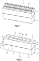
- the box contains a first plurality of tubes 2, in this case fourteen, arranged substantially parallel to each other. Each end of each tube opens out of the box 1 and defines in its interior an enclosure 2a for accommodating the electrochemical elements. Of course, in order to avoid short circuits, the electrochemical elements are electrically isolated from the tubes.
- These tubes are of circular section in the mode of achievement represented in figures 2 and 3 and adapted to regulate the temperature of cylindrical electrochemical elements. They may also admit a square or elliptical section in the case where the electrochemical elements to be regulated are prismatic or oblong.
- the tubes are preferably arranged inside the box in rows parallel to each other, the device comprising at least one row of at least two tubes, in this case in the example described, two rows of seven tubes.
- the tubes can be arranged in staggered rows.
- the box has a generally parallelepiped shape, two of the six faces being traversed by the plurality of tubes and the remaining four faces being referenced 8a to 8d.
- the space surrounding the fourteen tubes is compartmentalized according to a first V1 and a second V2 volumes by means of a partition C1 which extends transversely to the direction defined by the longitudinal axis of the tubes.
- the partition C1 is provided with means of communication M1 between the volume V1 and the volume V2, which thus allow the heat transfer liquids to flow from the volume V1 to the volume V2.
- these communication means M1 consist of a duct which extends outside the box but which is connected at its two ends to the wall 8d, said ends communicating for one with the volume V1 and for the other with the volume V2.
- the communication means M1 consist of a opening made in the partition C1. Of course, these means of communication may admit multiple and varied configurations.
- these communication means Mk may consist of one or more openings made in the partition Ck or in one or more ducts connecting the volume Vk and the volume Vk + 1, this or these ducts may extend inside. as on the outside of the box.
- the communication means Mk are arranged distal to the communication means Mk-1 of the previous partition. Indeed, the coolant arrives from the space Vk-1 in the space Vk through the communication means Mk-1 and enters the space Vk + 1 through the communication means Mk. more possible the communication means Mk-1 and Mk, the heat transfer liquid is forced to flow over an entire area Vk space. In such a way that the heat transfer fluid also travels the entire extent of the space Vk + 1, the communication means Mk are arranged distally with respect to the communication means Mk + 1 of the following partition.
- distal arranged characteristic is meant the fact that the communication means Mk and Mk + 1 are arranged so as to be as far as possible from each other. More specifically, the communication means Mk are formed near one of the walls of the box or on the wall itself, while the communication means Mk + 1 and Mk-1 are formed near the opposite wall.
- the device provides means 4 for admitting the heat transfer liquid inside the volume V1, and means 3 for discharging said liquid outside the volume V2.
- the communication means M1 are arranged distally with respect to the intake means 4 and the discharge means 3 of the coolant.
- arranged distally means that the communication means M1 are arranged so as to be as far as possible from the intake means 4 and the delivery means 3. More specifically, the communication means M1 are formed near the wall 8c of the box in the case where they consist of an opening or on the wall itself in the case where they consist of a pipe, while the inlet means 4 and the discharge means 3 are arranged on the opposite wall 8d.
- the positioning of the intake means 4, the discharge means 3 and the M1 communication means is chosen so that the liquid travels an extent along the length rather than the width of the partition C1.
- the device also admits means 4 to admit the heat transfer liquid inside the volume V1 defined by the first partition of the series, and means 3 for discharging said liquid outside the volume Vn defined by the last partition of the series.
- the communication means M1 of the first partition of the series are then arranged distally with respect to the admission means 4, just as the communication means Mn of the last partition of the series are also arranged distally relative to each other. the discharge means 3 of the coolant.
- the term "arranged in a distal manner" means that the communication means M1 and Mn are arranged so as to be respectively as far as possible from the intake means 4 and the delivery means 3. More precisely , the communication means M1 and Mn are respectively formed close to the wall of the box opposite to the wall near which the intake means 4 and the delivery means 3 are located.
- the coolant travels n-1 back and forth one way.
- the heat transfer liquid travels back and forth.
- the positioning of the intake means 4, the discharge means 3 and the communication means Mk is chosen so that the liquid travels an extent along the length rather than the width of the partition Ck.
- the device comprises a second plurality of tubes 7 serving to pass means for fixing said device on a support.
- the fastening means may be tie rods.
- the box and the tubes can be steel or aluminum.
- the manufacturing method of the regulating device implements manufacturing steps known to those skilled in the art and including in particular the supply of tubes and six plates, two of which are recessed in a controlled manner. relative to the diameter of the tubes.
- the assembly of the plates enclosing the tubes positioned facing the recesses of the plates is preferably performed by welding.
- the box and the tubes may be made of elastomer or plastic, these materials preferably comprising fillers intended to improve the mechanical properties.
- the manufacturing process then comprises at least one molding step.
- the inner surface of the tubes 2 may be treated wholly or partially so as to be electrically non-conductive, highly thermally conductive, or so as to have a coating intended to reduce its coefficient of friction.
- the coatings conferring electrical insulation on the inner surface of the tubes are preferably coating coatings made of silicone or based on ethylene-propylene-diene monomers.
- the coatings conferring on the inner surface of the tubes a thermally conductive character are preferably based on silicone gel and certain resins.
- the coatings imparting a lubricating character to the inner surface of the tubes are preferably solid lubricants such as graphite, zinc oxide, boron nitride, molybdenum disulphide, graphite fluoride, tin sulphides, bismuth sulphides, or tungsten disulfide, fluoride calcium, some thiosulfates, polytetrafluoroethylene or some polyamides.
- solid lubricants such as graphite, zinc oxide, boron nitride, molybdenum disulphide, graphite fluoride, tin sulphides, bismuth sulphides, or tungsten disulfide, fluoride calcium, some thiosulfates, polytetrafluoroethylene or some polyamides.
- the invention also relates to a method for mounting electrochemical elements in a thermal control device as described above.
- the tubes 2 are expanded by heating the device.
- the tubes 2 are expanded by evacuating the internal spaces Vk to the box at a pressure, for example less than atmospheric pressure.
- each electrochemical element having a lateral surface, a bottom and a lid is in contact with at least 75% of its lateral surface with the box.
- heat transfer liquids it is possible to use any type and in particular demineralized water particularly efficient in terms of heat exchange, mixtures of demineralized water and ethylene glycol, mineral oils, dielectric fluids perfluorocarbon type.
- thermo-fluidic simulations have been carried out to validate the invention with respect to existing solutions and more particularly with respect to solutions using temperature control devices consisting of a rigid water jacket ("water jacket"). ) which comprises a rigid envelope in which a coolant circulates.
- the heat transfer fluid is 50/50 brine regulated at 20 ° C at a flow rate of 3L / min.
- the power dissipated P by each electrochemical element in steady state is 38W.
- Designation description Rigid water jacket Solution in rigid polypropylene passing between the 2 rows of elements. Contact on 20% of the lateral surface Existing solution Soft water jacket Solution in flexible polyurethane passing and swelling between the 2 rows of elements. Contact on 20% of the lateral surface Existing solution Elastomer device.
- Invention Metal device In accordance with the invention
- Invention Plastic device In accordance with the invention
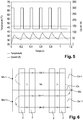
- the figure 4 highlights that the existing solutions of the "water jacket” type do not prevent a rise in temperature for an exchange coefficient with the electrochemical elements H equal to 22.8 W / m 2 .K.
- the figure 5 shows however that the solutions according to the invention can contain the rise in temperature with a heat exchange coefficient H reaching 100W / m 2 .K, more than four times that of existing solutions of the type "water jacket ".
- the invention thus makes it possible to keep the electrochemical elements below 40 ° C for high power applications.
- This control device has above all a maximized cooling / heating capacity insofar as the coolant surrounds the entire side surface of the electrochemical elements.
- This solution also makes it possible to have a thermal homogeneity on all the electrochemical elements because of the hydraulic architecture in return. Indeed, during its journey, the coolant defines a temperature gradient in all spaces Vk it crosses by reversing the direction of the gradient each time it passes through a partition. As a result, the sum of the heat exchanges in the direction defined by the longitudinal axis of the tubes is constant at the level of each tube, and consequently at the level of each electrochemical element. The latter thus receive an identical cooling / heating.
- This thermal regulation device has other significant advantages, insofar as it makes it possible to de-correlate the heat-transfer liquid of the electrochemical elements, the coolant being no longer in contact with the wall of the electrochemical element.
- the sealing and electrical insulation characteristics of the device not only make it possible to widen the possibilities of choice of heat transfer liquids but also to integrate the device into an open structure.
- the assembly of the electrochemical elements in the regulating device can be automated as well as the integration of the module constituted by the assembly of the regulating device and the electrochemical elements, in a production line of generators. electrochemical.
Landscapes
- Engineering & Computer Science (AREA)
- Manufacturing & Machinery (AREA)
- Chemical & Material Sciences (AREA)
- Chemical Kinetics & Catalysis (AREA)
- Electrochemistry (AREA)
- General Chemical & Material Sciences (AREA)
- Secondary Cells (AREA)
Claims (13)
- Verfahren zur Herstellung von einer Batterie, die eine Vorrichtung zur Wärmeregulierung der elektrischen Elemente aufweist,
wobei die Vorrichtung einen flüssigkeitsdichten Kasten (1) aufweist, umfassend:- mehrere Rohre (2, 7), die im Wesentlichen parallel angeordnet sind, wobei jedes der Enden der Rohre an der Außenseite des Kastens (1) mündet,- n Trennwände Ck, n ≥ 1 und 1 ≤ k ≤ n, die sich quer zu der Richtung, die von der Längsachse der Rohre definiert ist, derart erstrecken, um den Raum, der die mehreren Rohre im Inneren des Kastens umgibt, nach n+1 Volumen V zu unterteilen,wobei die Vorrichtung mit Mitteln Mk versehen ist, die ermöglichen, eine Verbindung zwischen dem Volumen Vk und dem Volumen Vk+1 zu erstellen, die durch die Trennwand Ck getrennt sind,- wobei die Verbindungsmittel Mk distal in Bezug auf die Mittel MK-1 zum Verbinden zwischen dem Volumen Vk-1 und dem Volumen Vk, die durch die Trennwand Ck-1 getrennt sind, und in Bezug auf die Mittel Mk+1 zum Verbinden zwischen dem Volumen Vk+1 und dem Volumen Vk+2, die durch die Trennwand Ck+1 getrennt sind, angeordnet sind,wobei die Vorrichtung ebenfalls mit Mitteln zum Einlassen (4) einer Wärmeträgerflüssigkeit ins Innere des Volumens V1, das durch die erste Trennwand definiert ist, und Mittel zum Auslassen (3) der Flüssigkeit außerhalb des definierten Volumens Vn+1 versehen ist, das von der letzten Trennwand definiert ist,
wobei die Verbindungsmittel M1 und Mn der ersten und der zweiten Trennwand der Serie jeweils distal in Bezug auf die Mittel zum Einlassen (4) und die Mittel zum Auslassen (3) der Wärmeträgerflüssigkeit angeordnet sind,
wobei die Batterie ferner elektrochemische Elemente aufweist, die in den Rohren (2) der Vorrichtung zur Wärmeregulierung untergebracht sind, wobei die elektrochemischen Elemente gegenüber den Rohren elektrisch isoliert sind, und
wobei das Verfahren mindestens einen Schritt der Montage der elektrochemischen Elemente in den Rohren (2) der Vorrichtung zur Regulierung aufweist, wobei dieser Schritt das Ausdehnen der Rohre (2) aufweist. - Verfahren zur Herstellung nach Anspruch 1, dadurch gekennzeichnet, dass die Rohre mindestens in einer Reihe angeordnet sind, die mindestens zwei Rohre aufweist.
- Verfahren zur Herstellung nach einem der vorhergehenden Ansprüche, dadurch gekennzeichnet, dass die Mittel Mk, die ermöglichen, eine Verbindung zwischen dem Volumen Vk und dem Volumen Vk+1 zu erstellen, aus einer oder mehreren Öffnungen gebildet sind, die in der Trennwand Ck ausgebildet sind.
- Verfahren zur Herstellung nach einem der Ansprüche 1 oder 2, dadurch gekennzeichnet, dass die Mittel Mk, die ermöglichen, eine Verbindung zwischen dem Volumen Vk und dem Volumen Vk+1 zu erstellen, aus einer oder mehreren Leitungen gebildet sind, die im Inneren des Kastens angeordnet sind.
- Verfahren zur Herstellung nach einem der Ansprüche 1 oder 2, dadurch gekennzeichnet, dass die Mittel Mk, die ermöglichen, eine Verbindung zwischen dem Volumen Vk und dem Volumen Vk+1 zu erstellen, aus einer oder mehreren Öffnungen, die in der Trennwand Ck ausgebildet sind, und aus einer oder mehreren Leitungen gebildet sind, die im Inneren des Kastens angeordnet sind.
- Verfahren zur Herstellung nach einem der vorhergehenden Ansprüche, dadurch gekennzeichnet, dass der Querschnitt der Rohre kreisförmig oder rechteckig ist.
- Verfahren zur Herstellung nach einem der vorhergehenden Ansprüche, dadurch gekennzeichnet, dass der Kasten und die Rohre der Vorrichtung aus Stahl oder aus Aluminium sind.
- Verfahren zur Herstellung nach einem der vorhergehenden Ansprüche, dadurch gekennzeichnet, dass der Kasten und die Rohre der Vorrichtung aus Elastomer oder aus Kunststoff sind, wobei das Elastomer oder der Kunststoff vorzugsweise Füllstoffe umfasst.
- Verfahren zur Herstellung nach einem der vorhergehenden Ansprüche, dadurch gekennzeichnet, dass die Innenfläche der Rohre (2) vollständig oder teilweise derart behandelt ist, um elektrisch nicht leitfähig und/oder thermisch hoch leitfähig zu sein und/oder um eine Beschichtung aufzuweisen, die dazu bestimmt ist, ihren Reibungskoeffizienten zu verringern.
- Verfahren zur Herstellung nach einem der vorhergehenden Ansprüche, dadurch gekennzeichnet, dass ein Teil der Rohre (7) für den Durchgang von Befestigungsmitteln der Vorrichtung auf einem Träger geeignet ist.
- Verfahren zur Herstellung nach einem der vorhergehenden Ansprüche, dadurch gekennzeichnet, dass jedes elektrochemische Element eine Seitenfläche, einen Boden und einen Deckel aufweist, wobei mindestens 75 % der Seitenfläche, vorzugsweise mindestens 90 %, insbesondere 100 % mit dem Kasten in Kontakt sind.
- Verfahren zur Herstellung einer Batterie nach Anspruch 1, dadurch gekennzeichnet, dass das Ausdehnen der Rohre (2) durch Erhitzen der Vorrichtung und insbesondere der Rohre durchgeführt wird, wobei die Vorrichtung aus Stahl oder aus Aluminium besteht.
- Verfahren zur Herstellung einer Batterie nach Anspruch 12, dadurch gekennzeichnet, dass das Ausdehnen der Rohre (2) durch unter Vakuum setzen der Innenräume des Kastens durchgeführt wird, wobei die Vorrichtung aus Elastomer besteht.
Applications Claiming Priority (1)
| Application Number | Priority Date | Filing Date | Title |
|---|---|---|---|
| FR1550330A FR3031840B1 (fr) | 2015-01-15 | 2015-01-15 | Batterie dotee d'un dispositif de regulation thermique d'elements electrochimiques, procede de fabrication associe |
Publications (2)
| Publication Number | Publication Date |
|---|---|
| EP3046178A1 EP3046178A1 (de) | 2016-07-20 |
| EP3046178B1 true EP3046178B1 (de) | 2018-11-28 |
Family
ID=53404642
Family Applications (1)
| Application Number | Title | Priority Date | Filing Date |
|---|---|---|---|
| EP16150679.5A Not-in-force EP3046178B1 (de) | 2015-01-15 | 2016-01-08 | Batterie, die mit einer vorrichtung zur wärmeregulierung der elektrochemischen elemente ausgestattet ist, und entsprechendes herstellungsverfahren |
Country Status (3)
| Country | Link |
|---|---|
| US (1) | US20160211562A1 (de) |
| EP (1) | EP3046178B1 (de) |
| FR (1) | FR3031840B1 (de) |
Families Citing this family (7)
| Publication number | Priority date | Publication date | Assignee | Title |
|---|---|---|---|---|
| FR3062521B1 (fr) * | 2018-04-10 | 2023-09-08 | Sogefi Air & Cooling | Unite de batterie avec des moyens de regulation de la temperature integres au boitier |
| IT201800006642A1 (it) * | 2018-06-25 | 2019-12-25 | Modulo di alimentazione elettrica e metodo per assemblarlo | |
| SG11202100353RA (en) * | 2018-07-25 | 2021-02-25 | Lubrizol Corp | Aqueous heat transfer system and method of dispersing heat from electrical componentry |
| DE102019215775A1 (de) | 2019-10-14 | 2021-04-15 | Robert Bosch Gmbh | Batteriemodul mit wenigstens einer Einzelzelle und einem Zellhalter zur Aufnahme der wenigstens einen Einzelzelle sowie ein Verfahren zur Herstellung eines solchen Batteriemoduls |
| CN115911662B (zh) * | 2023-01-03 | 2025-06-03 | 楚能新能源股份有限公司 | 一种沉浸式液冷电池模组结构及其装配方法 |
| KR20250113649A (ko) * | 2024-01-19 | 2025-07-28 | 삼성에스디아이 주식회사 | 에너지 저장 장치 |
| CN120261832B (zh) * | 2025-03-31 | 2025-09-30 | 东莞市龙谊电子科技有限公司 | 一种动力电池组热管理芯片及系统 |
Family Cites Families (21)
| Publication number | Priority date | Publication date | Assignee | Title |
|---|---|---|---|---|
| JP3044975B2 (ja) | 1992-12-10 | 2000-05-22 | トヨタ自動車株式会社 | 電気自動車のバッテリ加温装置 |
| DE4416236A1 (de) * | 1994-05-07 | 1995-11-09 | Schmidt Bretten W Gmbh | Wärmeaustauscher |
| JPH1154157A (ja) | 1997-08-04 | 1999-02-26 | Toyota Motor Corp | 熱交換装置及びバッテリケース |
| DE19750069A1 (de) | 1997-11-12 | 1999-05-20 | Varta Batterie | Akkumulatorenbatterie mit Temperiervorrichtung |
| FR2774215B1 (fr) * | 1998-01-29 | 2000-02-25 | Alsthom Cge Alcatel | Batterie monobloc etanche munie d'un dispositif de refroidissement |
| US6479185B1 (en) * | 2000-04-04 | 2002-11-12 | Moltech Power Systems, Inc. | Extended life battery pack with active cooling |
| DE10034134A1 (de) | 2000-07-13 | 2002-01-31 | Daimler Chrysler Ag | Wärmetauscherstruktur für mehrere elektrochemische Speicherzellen |
| US20020177035A1 (en) | 2001-05-23 | 2002-11-28 | Alcatel | Thermal management blanketing and jacketing for battery system modules |
| DE10352046A1 (de) * | 2003-11-07 | 2005-06-09 | Daimlerchrysler Ag | Batterie mit wenigstens einer elektrochemischen Speicherzelle und einer Kühleinrichtung |
| KR20090043566A (ko) * | 2006-09-18 | 2009-05-06 | 마그나 스티어 파르초이크테시닉 아게 운트 코. 카게 | 모듈 방식의 배터리 유닛 |
| DE102007050506A1 (de) * | 2007-10-19 | 2009-04-23 | Behr Gmbh & Co. Kg | Vorrichtung zur elektrischen Energiespeicherung |
| WO2010056750A2 (en) * | 2008-11-12 | 2010-05-20 | Johnson Controls - Saft Advanced Power Solutions Llc | Battery system with heat exchanger |
| JP4947075B2 (ja) * | 2009-03-23 | 2012-06-06 | トヨタ自動車株式会社 | 蓄電装置の温度調節構造 |
| US20100291419A1 (en) * | 2009-05-15 | 2010-11-18 | Sinoelectric Powertrain Corporation | Battery pack heat exchanger, systems, and methods |
| WO2011065675A2 (ko) * | 2009-11-27 | 2011-06-03 | (주)브이이엔에스 | 배터리 |
| KR101206272B1 (ko) * | 2010-11-22 | 2012-11-30 | 주식회사 한국쿨러 | 전기 차량용 전지셀의 히트 싱크 및 그를 이용한 전지셀 모듈 |
| US8647763B2 (en) * | 2011-06-30 | 2014-02-11 | Tesla Motors, Inc. | Battery coolant jacket |
| US8906541B2 (en) * | 2012-01-27 | 2014-12-09 | Tesla Motors, Inc. | Battery module with integrated thermal management system |
| GB201303814D0 (en) * | 2013-03-04 | 2013-04-17 | Mclaren Automotive Ltd | Battery structure |
| US9912019B2 (en) * | 2013-05-20 | 2018-03-06 | Hamilton Sundstrand Corporation | Thermal management of electrical storage devices by coolant pool |
| CN103996888B (zh) * | 2014-05-26 | 2016-11-23 | 华霆(合肥)动力技术有限公司 | 一种锂电池的蜂窝式液冷装置 |
-
2015
- 2015-01-15 FR FR1550330A patent/FR3031840B1/fr not_active Expired - Fee Related
-
2016
- 2016-01-08 EP EP16150679.5A patent/EP3046178B1/de not_active Not-in-force
- 2016-01-13 US US14/994,584 patent/US20160211562A1/en not_active Abandoned
Non-Patent Citations (1)
| Title |
|---|
| None * |
Also Published As
| Publication number | Publication date |
|---|---|
| US20160211562A1 (en) | 2016-07-21 |
| EP3046178A1 (de) | 2016-07-20 |
| FR3031840B1 (fr) | 2017-01-13 |
| FR3031840A1 (fr) | 2016-07-22 |
Similar Documents
| Publication | Publication Date | Title |
|---|---|---|
| EP3046178A1 (de) | Batterie, die mit einer vorrichtung zur wärmeregulierung der elektrochemischen elemente ausgestattet ist, und entsprechendes herstellungsverfahren | |
| EP4062120A1 (de) | Thermisches managementsystem für eine elektrische komponente | |
| FR2975230A1 (fr) | Pack batterie avec dispositif de regulation thermique associe | |
| WO2020178519A1 (fr) | Dispositif de regulation thermique, notamment de refroidissement pour vehicule automobile | |
| EP1746672A2 (de) | Vorrichtung zur thermischen regelung | |
| FR3088994A1 (fr) | Échangeur de chaleur et système de refroidissement d’un fluide comprenant un tel échangeur de chaleur | |
| FR3011131A1 (fr) | Dispositif de gestion thermique de batterie et procede de fabrication associe | |
| FR3016479A1 (fr) | Plaque d'echange thermique pour gestion thermique de batterie et procede de fabrication associe | |
| FR2989841A1 (fr) | Dispositif de regulation thermique pour module de batteries. | |
| FR3061766A1 (fr) | Dispositif d'echange thermique, notamment pour la regulation thermique d'une batterie d'un vehicule automobile | |
| FR3086048A1 (fr) | Dispositif de regulation thermique, notamment de refroidissement | |
| EP3925018A1 (de) | Batterieeinheit und kraftfahrzeug mit mindestens einer solchen einheit | |
| FR2967246A1 (fr) | Echangeur de chaleur pour dispositif de stockage d'energie electrique | |
| FR3089689A1 (fr) | Batterie modulaire comprenant un systeme de conditionnement thermique | |
| WO2018020139A1 (fr) | Echangeur de chaleur, notamment pour la regulation thermique d'une unite de reserve d'energie, et ensemble forme dudit echangeur et de ladite unite | |
| WO2018127641A1 (fr) | Echangeur thermique à deux rangées de tubes pour la régulation thermique d'une batterie d'un véhicule automobile | |
| WO2022074144A1 (fr) | Dispositif de régulation thermique, notamment de refroidissement pour véhicule automobile | |
| EP3469290B1 (de) | Vorrichtung zur zentrierung in einem rohr | |
| EP3811432B1 (de) | Gehause mit einer modularen anordnung zur zirkulation eines wärmeübertragungsfluids in einer kraftfahrzeugbatterie | |
| FR3066263A1 (fr) | Collecteur constitutif d'un refroidisseur de batterie equipant un vehicule automobile | |
| EP3861587B1 (de) | System zur kühlung von batteriezellen für kraftfahrzeuge | |
| FR3095078A3 (fr) | Élément de bloc-batterie doté d’un espace entre les éléments de batterie pour acheminer un liquide caloporteur | |
| WO2021156563A1 (fr) | Dispositif de régulation de température d'un élément électrique susceptible de dégager de la chaleur en fonctionnement et pack-batterie comprenant un tel dispositif | |
| FR3028937A1 (fr) | Dispositif de conduction thermique, dispositif d'echange de chaleur comprenant le dispositif de conduction thermique et ensemble comprenant le dispositif d'echange de chaleur et un dispositif a refroidir | |
| EP3769364B1 (de) | Elektrisches lagerungselement für ein fahrzeug, das mit wärmerohren thermisch reguliert wird |
Legal Events
| Date | Code | Title | Description |
|---|---|---|---|
| PUAI | Public reference made under article 153(3) epc to a published international application that has entered the european phase |
Free format text: ORIGINAL CODE: 0009012 |
|
| AK | Designated contracting states |
Kind code of ref document: A1 Designated state(s): AL AT BE BG CH CY CZ DE DK EE ES FI FR GB GR HR HU IE IS IT LI LT LU LV MC MK MT NL NO PL PT RO RS SE SI SK SM TR |
|
| AX | Request for extension of the european patent |
Extension state: BA ME |
|
| RIN1 | Information on inventor provided before grant (corrected) |
Inventor name: FORGET, GUILLAUME Inventor name: POUYAU, LAURENT Inventor name: BERTIN, MATHIEU Inventor name: BOBINET, JULIEN |
|
| STAA | Information on the status of an ep patent application or granted ep patent |
Free format text: STATUS: REQUEST FOR EXAMINATION WAS MADE |
|
| 17P | Request for examination filed |
Effective date: 20170120 |
|
| RBV | Designated contracting states (corrected) |
Designated state(s): AL AT BE BG CH CY CZ DE DK EE ES FI FR GB GR HR HU IE IS IT LI LT LU LV MC MK MT NL NO PL PT RO RS SE SI SK SM TR |
|
| GRAP | Despatch of communication of intention to grant a patent |
Free format text: ORIGINAL CODE: EPIDOSNIGR1 |
|
| STAA | Information on the status of an ep patent application or granted ep patent |
Free format text: STATUS: GRANT OF PATENT IS INTENDED |
|
| INTG | Intention to grant announced |
Effective date: 20180626 |
|
| GRAS | Grant fee paid |
Free format text: ORIGINAL CODE: EPIDOSNIGR3 |
|
| GRAA | (expected) grant |
Free format text: ORIGINAL CODE: 0009210 |
|
| STAA | Information on the status of an ep patent application or granted ep patent |
Free format text: STATUS: THE PATENT HAS BEEN GRANTED |
|
| AK | Designated contracting states |
Kind code of ref document: B1 Designated state(s): AL AT BE BG CH CY CZ DE DK EE ES FI FR GB GR HR HU IE IS IT LI LT LU LV MC MK MT NL NO PL PT RO RS SE SI SK SM TR |
|
| REG | Reference to a national code |
Ref country code: CH Ref legal event code: EP |
|
| REG | Reference to a national code |
Ref country code: AT Ref legal event code: REF Ref document number: 1071309 Country of ref document: AT Kind code of ref document: T Effective date: 20181215 |
|
| REG | Reference to a national code |
Ref country code: DE Ref legal event code: R096 Ref document number: 602016007462 Country of ref document: DE |
|
| REG | Reference to a national code |
Ref country code: IE Ref legal event code: FG4D Free format text: LANGUAGE OF EP DOCUMENT: FRENCH |
|
| REG | Reference to a national code |
Ref country code: NL Ref legal event code: MP Effective date: 20181128 |
|
| REG | Reference to a national code |
Ref country code: LT Ref legal event code: MG4D |
|
| REG | Reference to a national code |
Ref country code: AT Ref legal event code: MK05 Ref document number: 1071309 Country of ref document: AT Kind code of ref document: T Effective date: 20181128 |
|
| PG25 | Lapsed in a contracting state [announced via postgrant information from national office to epo] |
Ref country code: BG Free format text: LAPSE BECAUSE OF FAILURE TO SUBMIT A TRANSLATION OF THE DESCRIPTION OR TO PAY THE FEE WITHIN THE PRESCRIBED TIME-LIMIT Effective date: 20190228 Ref country code: NO Free format text: LAPSE BECAUSE OF FAILURE TO SUBMIT A TRANSLATION OF THE DESCRIPTION OR TO PAY THE FEE WITHIN THE PRESCRIBED TIME-LIMIT Effective date: 20190228 Ref country code: IS Free format text: LAPSE BECAUSE OF FAILURE TO SUBMIT A TRANSLATION OF THE DESCRIPTION OR TO PAY THE FEE WITHIN THE PRESCRIBED TIME-LIMIT Effective date: 20190328 Ref country code: FI Free format text: LAPSE BECAUSE OF FAILURE TO SUBMIT A TRANSLATION OF THE DESCRIPTION OR TO PAY THE FEE WITHIN THE PRESCRIBED TIME-LIMIT Effective date: 20181128 Ref country code: LT Free format text: LAPSE BECAUSE OF FAILURE TO SUBMIT A TRANSLATION OF THE DESCRIPTION OR TO PAY THE FEE WITHIN THE PRESCRIBED TIME-LIMIT Effective date: 20181128 Ref country code: LV Free format text: LAPSE BECAUSE OF FAILURE TO SUBMIT A TRANSLATION OF THE DESCRIPTION OR TO PAY THE FEE WITHIN THE PRESCRIBED TIME-LIMIT Effective date: 20181128 Ref country code: HR Free format text: LAPSE BECAUSE OF FAILURE TO SUBMIT A TRANSLATION OF THE DESCRIPTION OR TO PAY THE FEE WITHIN THE PRESCRIBED TIME-LIMIT Effective date: 20181128 Ref country code: ES Free format text: LAPSE BECAUSE OF FAILURE TO SUBMIT A TRANSLATION OF THE DESCRIPTION OR TO PAY THE FEE WITHIN THE PRESCRIBED TIME-LIMIT Effective date: 20181128 Ref country code: AT Free format text: LAPSE BECAUSE OF FAILURE TO SUBMIT A TRANSLATION OF THE DESCRIPTION OR TO PAY THE FEE WITHIN THE PRESCRIBED TIME-LIMIT Effective date: 20181128 |
|
| PG25 | Lapsed in a contracting state [announced via postgrant information from national office to epo] |
Ref country code: GR Free format text: LAPSE BECAUSE OF FAILURE TO SUBMIT A TRANSLATION OF THE DESCRIPTION OR TO PAY THE FEE WITHIN THE PRESCRIBED TIME-LIMIT Effective date: 20190301 Ref country code: PT Free format text: LAPSE BECAUSE OF FAILURE TO SUBMIT A TRANSLATION OF THE DESCRIPTION OR TO PAY THE FEE WITHIN THE PRESCRIBED TIME-LIMIT Effective date: 20190328 Ref country code: SE Free format text: LAPSE BECAUSE OF FAILURE TO SUBMIT A TRANSLATION OF THE DESCRIPTION OR TO PAY THE FEE WITHIN THE PRESCRIBED TIME-LIMIT Effective date: 20181128 Ref country code: RS Free format text: LAPSE BECAUSE OF FAILURE TO SUBMIT A TRANSLATION OF THE DESCRIPTION OR TO PAY THE FEE WITHIN THE PRESCRIBED TIME-LIMIT Effective date: 20181128 Ref country code: AL Free format text: LAPSE BECAUSE OF FAILURE TO SUBMIT A TRANSLATION OF THE DESCRIPTION OR TO PAY THE FEE WITHIN THE PRESCRIBED TIME-LIMIT Effective date: 20181128 |
|
| PG25 | Lapsed in a contracting state [announced via postgrant information from national office to epo] |
Ref country code: NL Free format text: LAPSE BECAUSE OF FAILURE TO SUBMIT A TRANSLATION OF THE DESCRIPTION OR TO PAY THE FEE WITHIN THE PRESCRIBED TIME-LIMIT Effective date: 20181128 |
|
| PG25 | Lapsed in a contracting state [announced via postgrant information from national office to epo] |
Ref country code: CZ Free format text: LAPSE BECAUSE OF FAILURE TO SUBMIT A TRANSLATION OF THE DESCRIPTION OR TO PAY THE FEE WITHIN THE PRESCRIBED TIME-LIMIT Effective date: 20181128 Ref country code: DK Free format text: LAPSE BECAUSE OF FAILURE TO SUBMIT A TRANSLATION OF THE DESCRIPTION OR TO PAY THE FEE WITHIN THE PRESCRIBED TIME-LIMIT Effective date: 20181128 Ref country code: IT Free format text: LAPSE BECAUSE OF FAILURE TO SUBMIT A TRANSLATION OF THE DESCRIPTION OR TO PAY THE FEE WITHIN THE PRESCRIBED TIME-LIMIT Effective date: 20181128 Ref country code: PL Free format text: LAPSE BECAUSE OF FAILURE TO SUBMIT A TRANSLATION OF THE DESCRIPTION OR TO PAY THE FEE WITHIN THE PRESCRIBED TIME-LIMIT Effective date: 20181128 |
|
| REG | Reference to a national code |
Ref country code: DE Ref legal event code: R097 Ref document number: 602016007462 Country of ref document: DE |
|
| PG25 | Lapsed in a contracting state [announced via postgrant information from national office to epo] |
Ref country code: MC Free format text: LAPSE BECAUSE OF FAILURE TO SUBMIT A TRANSLATION OF THE DESCRIPTION OR TO PAY THE FEE WITHIN THE PRESCRIBED TIME-LIMIT Effective date: 20181128 Ref country code: SK Free format text: LAPSE BECAUSE OF FAILURE TO SUBMIT A TRANSLATION OF THE DESCRIPTION OR TO PAY THE FEE WITHIN THE PRESCRIBED TIME-LIMIT Effective date: 20181128 Ref country code: EE Free format text: LAPSE BECAUSE OF FAILURE TO SUBMIT A TRANSLATION OF THE DESCRIPTION OR TO PAY THE FEE WITHIN THE PRESCRIBED TIME-LIMIT Effective date: 20181128 Ref country code: SM Free format text: LAPSE BECAUSE OF FAILURE TO SUBMIT A TRANSLATION OF THE DESCRIPTION OR TO PAY THE FEE WITHIN THE PRESCRIBED TIME-LIMIT Effective date: 20181128 Ref country code: RO Free format text: LAPSE BECAUSE OF FAILURE TO SUBMIT A TRANSLATION OF THE DESCRIPTION OR TO PAY THE FEE WITHIN THE PRESCRIBED TIME-LIMIT Effective date: 20181128 |
|
| REG | Reference to a national code |
Ref country code: CH Ref legal event code: PL |
|
| PG25 | Lapsed in a contracting state [announced via postgrant information from national office to epo] |
Ref country code: LU Free format text: LAPSE BECAUSE OF NON-PAYMENT OF DUE FEES Effective date: 20190108 |
|
| PLBE | No opposition filed within time limit |
Free format text: ORIGINAL CODE: 0009261 |
|
| STAA | Information on the status of an ep patent application or granted ep patent |
Free format text: STATUS: NO OPPOSITION FILED WITHIN TIME LIMIT |
|
| REG | Reference to a national code |
Ref country code: BE Ref legal event code: MM Effective date: 20190131 |
|
| REG | Reference to a national code |
Ref country code: IE Ref legal event code: MM4A |
|
| PG25 | Lapsed in a contracting state [announced via postgrant information from national office to epo] |
Ref country code: SI Free format text: LAPSE BECAUSE OF FAILURE TO SUBMIT A TRANSLATION OF THE DESCRIPTION OR TO PAY THE FEE WITHIN THE PRESCRIBED TIME-LIMIT Effective date: 20181128 |
|
| 26N | No opposition filed |
Effective date: 20190829 |
|
| PG25 | Lapsed in a contracting state [announced via postgrant information from national office to epo] |
Ref country code: BE Free format text: LAPSE BECAUSE OF NON-PAYMENT OF DUE FEES Effective date: 20190131 |
|
| PG25 | Lapsed in a contracting state [announced via postgrant information from national office to epo] |
Ref country code: LI Free format text: LAPSE BECAUSE OF NON-PAYMENT OF DUE FEES Effective date: 20190131 Ref country code: CH Free format text: LAPSE BECAUSE OF NON-PAYMENT OF DUE FEES Effective date: 20190131 |
|
| PG25 | Lapsed in a contracting state [announced via postgrant information from national office to epo] |
Ref country code: IE Free format text: LAPSE BECAUSE OF NON-PAYMENT OF DUE FEES Effective date: 20190108 |
|
| PG25 | Lapsed in a contracting state [announced via postgrant information from national office to epo] |
Ref country code: TR Free format text: LAPSE BECAUSE OF FAILURE TO SUBMIT A TRANSLATION OF THE DESCRIPTION OR TO PAY THE FEE WITHIN THE PRESCRIBED TIME-LIMIT Effective date: 20181128 |
|
| PG25 | Lapsed in a contracting state [announced via postgrant information from national office to epo] |
Ref country code: MT Free format text: LAPSE BECAUSE OF FAILURE TO SUBMIT A TRANSLATION OF THE DESCRIPTION OR TO PAY THE FEE WITHIN THE PRESCRIBED TIME-LIMIT Effective date: 20181128 |
|
| PG25 | Lapsed in a contracting state [announced via postgrant information from national office to epo] |
Ref country code: CY Free format text: LAPSE BECAUSE OF FAILURE TO SUBMIT A TRANSLATION OF THE DESCRIPTION OR TO PAY THE FEE WITHIN THE PRESCRIBED TIME-LIMIT Effective date: 20181128 |
|
| PG25 | Lapsed in a contracting state [announced via postgrant information from national office to epo] |
Ref country code: HU Free format text: LAPSE BECAUSE OF FAILURE TO SUBMIT A TRANSLATION OF THE DESCRIPTION OR TO PAY THE FEE WITHIN THE PRESCRIBED TIME-LIMIT; INVALID AB INITIO Effective date: 20160108 |
|
| PG25 | Lapsed in a contracting state [announced via postgrant information from national office to epo] |
Ref country code: MK Free format text: LAPSE BECAUSE OF FAILURE TO SUBMIT A TRANSLATION OF THE DESCRIPTION OR TO PAY THE FEE WITHIN THE PRESCRIBED TIME-LIMIT Effective date: 20181128 |
|
| P01 | Opt-out of the competence of the unified patent court (upc) registered |
Effective date: 20230514 |
|
| PGFP | Annual fee paid to national office [announced via postgrant information from national office to epo] |
Ref country code: DE Payment date: 20240130 Year of fee payment: 9 Ref country code: GB Payment date: 20240130 Year of fee payment: 9 |
|
| PGFP | Annual fee paid to national office [announced via postgrant information from national office to epo] |
Ref country code: FR Payment date: 20240111 Year of fee payment: 9 |
|
| REG | Reference to a national code |
Ref country code: DE Ref legal event code: R119 Ref document number: 602016007462 Country of ref document: DE |
|
| GBPC | Gb: european patent ceased through non-payment of renewal fee |
Effective date: 20250108 |
|
| PG25 | Lapsed in a contracting state [announced via postgrant information from national office to epo] |
Ref country code: DE Free format text: LAPSE BECAUSE OF NON-PAYMENT OF DUE FEES Effective date: 20250801 |
|
| PG25 | Lapsed in a contracting state [announced via postgrant information from national office to epo] |
Ref country code: GB Free format text: LAPSE BECAUSE OF NON-PAYMENT OF DUE FEES Effective date: 20250108 |
|
| PG25 | Lapsed in a contracting state [announced via postgrant information from national office to epo] |
Ref country code: FR Free format text: LAPSE BECAUSE OF NON-PAYMENT OF DUE FEES Effective date: 20250131 |