EP3468239B1 - Verfahren und vorrichtung zur verwaltung des imsi-zustands einer endgerätevorrichtung - Google Patents
Verfahren und vorrichtung zur verwaltung des imsi-zustands einer endgerätevorrichtung Download PDFInfo
- Publication number
- EP3468239B1 EP3468239B1 EP16907724.5A EP16907724A EP3468239B1 EP 3468239 B1 EP3468239 B1 EP 3468239B1 EP 16907724 A EP16907724 A EP 16907724A EP 3468239 B1 EP3468239 B1 EP 3468239B1
- Authority
- EP
- European Patent Office
- Prior art keywords
- terminal device
- imsi
- request message
- network node
- core network
- Prior art date
- Legal status (The legal status is an assumption and is not a legal conclusion. Google has not performed a legal analysis and makes no representation as to the accuracy of the status listed.)
- Active
Links
Images

Classifications
-
- H—ELECTRICITY
- H04—ELECTRIC COMMUNICATION TECHNIQUE
- H04W—WIRELESS COMMUNICATION NETWORKS
- H04W8/00—Network data management
- H04W8/18—Processing of user or subscriber data, e.g. subscribed services, user preferences or user profiles; Transfer of user or subscriber data
- H04W8/20—Transfer of user or subscriber data
- H04W8/205—Transfer to or from user equipment or user record carrier
-
- H—ELECTRICITY
- H04—ELECTRIC COMMUNICATION TECHNIQUE
- H04W—WIRELESS COMMUNICATION NETWORKS
- H04W4/00—Services specially adapted for wireless communication networks; Facilities therefor
- H04W4/02—Services making use of location information
- H04W4/025—Services making use of location information using location based information parameters
-
- H—ELECTRICITY
- H04—ELECTRIC COMMUNICATION TECHNIQUE
- H04W—WIRELESS COMMUNICATION NETWORKS
- H04W60/00—Affiliation to network, e.g. registration; Terminating affiliation with the network, e.g. de-registration
-
- H—ELECTRICITY
- H04—ELECTRIC COMMUNICATION TECHNIQUE
- H04W—WIRELESS COMMUNICATION NETWORKS
- H04W8/00—Network data management
- H04W8/02—Processing of mobility data, e.g. registration information at HLR [Home Location Register] or VLR [Visitor Location Register]; Transfer of mobility data, e.g. between HLR, VLR or external networks
- H04W8/04—Registration at HLR or HSS [Home Subscriber Server]
-
- H—ELECTRICITY
- H04—ELECTRIC COMMUNICATION TECHNIQUE
- H04W—WIRELESS COMMUNICATION NETWORKS
- H04W8/00—Network data management
- H04W8/22—Processing or transfer of terminal data, e.g. status or physical capabilities
- H04W8/24—Transfer of terminal data
-
- H—ELECTRICITY
- H04—ELECTRIC COMMUNICATION TECHNIQUE
- H04W—WIRELESS COMMUNICATION NETWORKS
- H04W8/00—Network data management
- H04W8/22—Processing or transfer of terminal data, e.g. status or physical capabilities
- H04W8/24—Transfer of terminal data
- H04W8/245—Transfer of terminal data from a network towards a terminal
-
- Y—GENERAL TAGGING OF NEW TECHNOLOGICAL DEVELOPMENTS; GENERAL TAGGING OF CROSS-SECTIONAL TECHNOLOGIES SPANNING OVER SEVERAL SECTIONS OF THE IPC; TECHNICAL SUBJECTS COVERED BY FORMER USPC CROSS-REFERENCE ART COLLECTIONS [XRACs] AND DIGESTS
- Y02—TECHNOLOGIES OR APPLICATIONS FOR MITIGATION OR ADAPTATION AGAINST CLIMATE CHANGE
- Y02D—CLIMATE CHANGE MITIGATION TECHNOLOGIES IN INFORMATION AND COMMUNICATION TECHNOLOGIES [ICT], I.E. INFORMATION AND COMMUNICATION TECHNOLOGIES AIMING AT THE REDUCTION OF THEIR OWN ENERGY USE
- Y02D30/00—Reducing energy consumption in communication networks
- Y02D30/70—Reducing energy consumption in communication networks in wireless communication networks
Definitions
- Embodiments of the present invention relate to communications technologies, and in particular, to a method, an apparatus, and a system for managing an international mobile subscriber identity (international mobile subscriber identification number, IMSI for short) status of a terminal device.
- IMSI international mobile subscriber identification number
- a function that a plurality of terminal devices share one number enables one mobile subscriber international integrated services digital network (integrated services digital network, ISDN)/public switched telephone network (public switched telephone network, PSTN for short) number (mobile station international ISDN number, MSISDN for short) to be corresponding to a plurality of subscriber identity module (subscriber identify module, SIM for short) cards, where different IMSIs are used for the SIM cards.
- ISDN integrated services digital network
- PSTN public switched telephone network
- MSISDN mobile station international ISDN number
- the terminal device may proactively initiate a location update process to activate an IMSI corresponding to the SIM card.
- a wearable device may be connected to a network by using a direct link such as an LTE radio access technology.
- the wearable device may be first connected to a relay node, and then connected to a network by using the relay node.
- An IMSI used for a SIM card of the wearable device and an IMSI used for a SIM card of the relay node may share a same MSISDN.
- the wearable device proactively initiates a location update process to activate the IMSI corresponding to the SIM card in the wearable device, power consumption of the wearable device is greatly increased. Therefore, an IMSI management method that can be used to reduce power consumption of the wearable device needs to be designed urgently, to meet a requirement of the Internet of Things application scenario.
- WO 2015/193609 A1 relates to a method for activating a subscriber card, referred to as first card, coupled with a first terminal capable of communicating with a second terminal coupled with an active second subscriber card.
- the terminals are capable of communicating with a first network of an operator, a terminal only being able to communicate with said first network if the associated card is active.
- the terminals can also communicate with one another via a second short-range network.
- the method includes in the first terminal, when a communication is possible between the two terminals via the second network, a step of transmitting to the second terminal a request to activate the first card on the first network, the request including the identifier of the first card.
- a method, an apparatus, and a system are provided for managing an IMSI status of a terminal device, to meet a requirement of an Internet of Things application scenario by using an IMSI management method that is used to reduce power consumption of a wearable device.
- an embodiment provides a method for managing an IMSI status of a terminal device, including: receiving, by a core network node, a first activation request message sent by a first terminal device, where the first activation request message carries an IMSI of a second terminal device and an IMSI status indication of the second terminal device, the first activation request message is used to request the core network node to set the IMSI of the second terminal device to an activated state or a deactivated state, and the IMSI status indication is used to indicate that an IMSI status is the activated state or the deactivated state; setting, by the core network node based on subscription information of the second terminal device, the IMSI of the second terminal device to the activated state or the deactivated state, and updating the IMSI status indication of the second terminal device; and sending, by the core network node, an activation response message to the first terminal device, where the activation response message carries the IMSI of the second terminal device and an updated IMSI status indication of the second terminal device
- the core network node receives the first activation request message sent by the first terminal device, where the first activation request message carries the IMSI of the second terminal device and the IMSI status indication of the second terminal device, the first activation request message is used to request the core network node to set the IMSI of the second terminal device to the activated state or the deactivated state, and the IMSI status indication is used to indicate that an IMSI status is the activated state or the deactivated state; sets, based on the subscription information of the second terminal device, the IMSI of the second terminal device to the activated state or the deactivated state, and updates the IMSI status indication of the second terminal device; and finally, sends, to the first terminal device, the activation response message that carries the IMSI of the second terminal device and the updated IMSI status indication of the second terminal device.
- the IMSI of the second terminal device is activated or deactivated through interaction between the first terminal device and the core network node, so that the second terminal device does not participate in activating or deactivating the IMSI of the second terminal device. Therefore, power consumption of the second terminal device can be reduced, and a requirement of an Internet of Things application scenario can be met.
- the wearable device such as a smartwatch
- the mobile phone may replace the smartwatch to implement an IMSI activation process. This can reduce energy consumption of the smartwatch and reduce costs.
- the setting, by the core network node based on subscription information of the second terminal device, the IMSI of the second terminal device to the activated state or the deactivated state includes: determining, by the core network node, that the IMSI of the second terminal device and an IMSI/IMSIs of one or more terminal devices other than the second terminal device are mapped to a same user identifier, where the user identifier is a mobile subscriber international ISDN/PSTN number MSISDN or a Session Initiation Protocol SIP identifier; obtaining, by the core network node, an IMSI status indication/IMSI status indications of the one or more terminal devices that are mapped to the same user identifier to which the IMSI of the second terminal device is mapped; and setting, by the core network node, the IMSI of the second terminal device to the activated state or the deactivated state based on the subscription information of the second terminal device and the IMSI status indication of the terminal device
- the first activation request message further includes a service type corresponding to the IMSI of the second terminal device, and the service type includes at least one of a short message service, voice, and data.
- the core network node can configure, for the second terminal device, the service type corresponding to the IMSI of the second terminal device.
- the first activation request message further includes priority information corresponding to an IMSI of the first terminal device and/or priority information corresponding to the IMSI of the second terminal device.
- an IMSI activation priority of a terminal device is set, so as to implement flexible management on an IMSI of the terminal device.
- the activation response message further includes an updated service type corresponding to the IMSI of the second terminal device and/or updated priority information corresponding to the IMSI of the second terminal device.
- the activation response message further includes the IMSI of the first terminal device and an updated IMSI status indication of the first terminal device, and/or an updated service type corresponding to the IMSI of the first terminal device, and/or updated priority information corresponding to the IMSI of the first terminal device.
- the first activation request message further includes the IMSI of the first terminal device and an IMSI status indication of the first terminal device.
- the first terminal device can not only activate and deactivate an IMSI of another terminal device (such as the second terminal device), but also activate and deactivate the IMSI of the first terminal device.
- the technical solution can be used to simultaneously activate IMSIs of a plurality of terminal devices (the first terminal device and the second terminal device in this embodiment), where the IMSIs may be corresponding to different service types, so as to meet diversified service requirements.
- the method may further include: determining, by the core network node, that the IMSI of the second terminal device and an IMSI/IMSIs of one or more terminal devices are mapped to a same user identifier, where the user identifier is an MSISDN or a SIP identifier; and when the core network node determines that IMSI statuses of the terminal devices mapped to the user identifier are all set to the deactivated state, determining, based on the subscription information of the second terminal device, to set the IMSI of the second terminal device to the activated state; or when the core network node determines that IMSI statuses of the terminal devices mapped to the user identifier are all set to the deactivated state, determining, based on subscription information
- the method may further include: determining, by the core network node, that the IMSI of the first terminal device and/or the IMSI of the second terminal device and an IMSI/IMSIs of one or more terminal devices are mapped to a same user identifier, where the user identifier is an MSISDN or a SIP identifier; and when the core network node determines that IMSI statuses of the terminal devices mapped to the user identifier are all set to the deactivated state, determining, based on subscription information of the first terminal device and the subscription information of the second terminal device, to set the IMSI of the first terminal device to the activated state or to set the IMSI of the second
- the first activation response message further includes the IMSI of the terminal device that is set to the activated state and that is of the one or more terminal devices and an IMSI status indication of the terminal device that is set to the activated state and that is of the one or more terminal devices.
- the method may further include: sending, by the core network node, a second activation request message to the terminal device that is set to the activated state, where the second activation request message carries the IMSI of the terminal device that is set to the activated state, the IMSI status indication of the terminal device that is set to the activated state, and an updated service type corresponding to the IMSI of the terminal device that is set to the activated state.
- the core network node proactively initiates an IMSI activation or deactivation process, and the terminal device activates or deactivates the IMSI of the terminal device, thereby increasing diversity of IMSI status management of the terminal device.
- an embodiment provides a method for managing an IMSI status of a terminal device, including: sending, by a first terminal device, a first activation request message to a core network node, where the first activation request message carries an IMSI of a second terminal device and an IMSI status indication of the second terminal device, the first activation request message is used to request the core network node to set the IMSI of the second terminal device to an activated state or a deactivated state, and the IMSI status indication is used to indicate that an IMSI status is the activated state or the deactivated state; and receiving, by the first terminal device, an activation response message sent by the core network node, where the activation response message carries the IMSI of the second terminal device and an updated IMSI status indication of the second terminal device, and the updated IMSI status indication of the second terminal device is an IMSI status indication of the second terminal device that is updated after the core network node sets, based on subscription information of the second terminal device, the IMS
- the IMSI of the second terminal device is activated or deactivated through interaction between the first terminal device and the core network node, so that the second terminal device does not participate in activating or deactivating the IMSI of the second terminal device. Therefore, power consumption of the second terminal device can be reduced, and a requirement of an Internet of Things application scenario can be met.
- the wearable device such as a smartwatch
- the mobile phone may replace the smartwatch to implement an IMSI activation process. This can reduce energy consumption of the smartwatch and reduce costs.
- the method before the sending, by a first terminal device, a first activation request message to a core network node, the method may further include: receiving, by the first terminal device, a third activation request message sent by the second terminal device, where the third activation request message carries the IMSI of the second terminal device and the IMSI status indication of the second terminal device; and correspondingly, after the receiving, by the first terminal device, an activation response message sent by the core network node, the method further includes: sending, by the first terminal device, the activation response message to the second terminal device.
- the third activation request message further includes a service type corresponding to the IMSI of the second terminal device, and the service type includes at least one of a short message service, voice, and data.
- the first activation request message may further include the service type corresponding to the IMSI of the second terminal device, and the service type includes at least one of a short message service, voice, and data.
- the first activation request message is generated based on the third activation request message.
- the first activation request message further includes an IMSI of the first terminal device and an IMSI status indication of the first terminal device; and correspondingly, the activation response message further includes the IMSI of the first terminal device and an updated IMSI status indication of the first terminal device.
- the first terminal device can not only activate and deactivate an IMSI of another terminal device (such as the second terminal device), but also activate and deactivate the IMSI of the first terminal device.
- the technical solution can be used to simultaneously activate IMSIs of a plurality of terminal devices (the first terminal device and the second terminal device in this embodiment), where the IMSIs may be corresponding to different service types, so as to meet diversified service requirements.
- the first activation request message further includes a service type corresponding to the IMSI of the first terminal device, and the service type includes at least one of a short message service, voice, and data.
- the first activation request message further includes priority information corresponding to the IMSI of the first terminal device and/or priority information corresponding to the IMSI of the second terminal device.
- an IMSI activation priority of a terminal device is set, so as to implement flexible management on an IMSI of the terminal device.
- the activation response message further includes at least one of an updated service type corresponding to the IMSI of the second terminal device, updated priority information corresponding to the IMSI of the second terminal device, an updated service type corresponding to the IMSI of the first terminal device, and updated priority information corresponding to the IMSI of the first terminal device.
- the method may further include: establishing, by the first terminal device, a communications link with the second terminal device, so that the second terminal device is connected to a network by using the first terminal device.
- the method before the sending, by a first terminal device, a first activation request message to a core network node, the method may further include: receiving, by the first terminal device, an operation instruction that is entered by a user and that is used to instruct to send the first activation request message; or generating, by the first terminal device, the first activation request message based on status change information of the first terminal device, where the status change information includes a battery level change and/or a radio link change.
- the method may further include: determining, by the first terminal device, to deactivate the IMSI of the first terminal device; and selecting, by the first terminal device, the second terminal device as a to-be-activated terminal device based on a pre-stored IMSI status indication of a terminal device that is mapped to a same user identifier to which the IMSI of the first terminal device is mapped, where the user identifier is an MSISDN or a SIP identifier.
- the first terminal device when the IMSI status indication of the second terminal device in the first activation request message indicates the deactivated state, and the IMSI status indication of the first terminal device in the first activation request message indicates the activated state, the first terminal device is a to-be-activated terminal device that is selected by the second terminal device, after determining to deactivate the IMSI of the second terminal device, based on a pre-stored IMSI status indication of a terminal device that is mapped to a same user identifier to which the IMSI of the second terminal device is mapped, where the user identifier is an MSISDN or a SIP identifier.
- an embodiment provides a method for managing an IMSI status of a terminal device, including: receiving, by a terminal device, a second activation request message sent by a core network node, where the second activation request message carries an IMSI of the terminal device and an IMSI status indication of the terminal device, the second activation request message is used to request the terminal device to set the IMSI of the terminal device to an activated state or a deactivated state, the terminal device is a terminal device that is set to the activated state and that is determined by the core network node based on an IMSI status indication carried in a first activation request message sent by a first terminal device, and the IMSI status indication is used to indicate that an IMSI status is the activated state or the deactivated state; and setting, by the terminal device based on the IMSI status indication of the terminal device, the IMSI of the terminal device to the activated state or the deactivated state.
- the core network node proactively initiates an IMSI activation or deactivation process, and the terminal device activates or deactivates the IMSI of the terminal device, thereby increasing diversity of IMSI status management of the terminal device.
- the second activation request message further includes a service type corresponding to the IMSI of the terminal device, and the service type includes at least one of a short message service, voice, and data.
- the core network node can configure, for the terminal device, the service type corresponding to the IMSI of the terminal device.
- an embodiment provides an apparatus for managing an IMSI status of a terminal device, where the apparatus is integrated into a core network node, and the apparatus includes: a receiving module, configured to receive a first activation request message sent by a first terminal device, where the first activation request message carries an IMSI of a second terminal device and an IMSI status indication of the second terminal device, the first activation request message is used to request the core network node to set the IMSI of the second terminal device to an activated state or a deactivated state, and the IMSI status indication is used to indicate that an IMSI status is the activated state or the deactivated state; a processing module, configured to: set, based on subscription information of the second terminal device, the IMSI of the second terminal device received by the receiving module to the activated state or the deactivated state, and update the IMSI status indication of the second terminal device; and a sending module, configured to send an activation response message to the first terminal device, where the activation response message carries
- the apparatus and the method design in the first aspect are based on a same idea, and a problem resolving principle of the apparatus is corresponding to the solution in the method design in the first aspect. Therefore, for implementation of the apparatus, refer to implementation of the method. Same parts are not described again.
- an embodiment provides an apparatus for managing an IMSI status of a terminal device, where the apparatus is integrated into a first terminal device, and the apparatus includes: a sending module, configured to send a first activation request message to a core network node, where the first activation request message carries an IMSI of a second terminal device and an IMSI status indication of the second terminal device, the first activation request message is used to request the core network node to set the IMSI of the second terminal device to an activated state or a deactivated state, and the IMSI status indication is used to indicate that an IMSI status is the activated state or the deactivated state; and a receiving module, configured to receive an activation response message sent by the core network node, where the activation response message carries the IMSI of the second terminal device and an updated IMSI status indication of the second terminal device, and the updated IMSI status indication of the second terminal device is an IMSI status indication of the second terminal device that is updated after the core network node sets,
- the apparatus and the method design in the second aspect are based on a same idea, and a problem resolving principle of the apparatus is corresponding to the solution in the method design in the second aspect. Therefore, for implementation of the apparatus, refer to implementation of the method. Same parts are not described again.
- an embodiment provides an apparatus for managing an IMSI status of a terminal device, where the apparatus is integrated into the terminal device, and the apparatus includes: a receiving module, configured to receive a second activation request message sent by a core network node, where the second activation request message carries an IMSI of the terminal device and an IMSI status indication of the terminal device, the second activation request message is used to request the terminal device to set the IMSI of the terminal device to an activated state or a deactivated state, the terminal device is a terminal device that is set to the activated state and that is determined by the core network node based on an IMSI status indication carried in a first activation request message sent by a first terminal device, and the IMSI status indication is used to indicate that an IMSI status is the activated state or the deactivated state; and a processing module, configured to set the IMSI of the terminal device to the activated state or the deactivated state based on the IMSI status indication of the terminal device in the second activ
- the apparatus and the method design in the third aspect are based on a same idea, and a problem resolving principle of the apparatus is corresponding to the solution in the method design in the third aspect. Therefore, for implementation of the apparatus, refer to implementation of the method. Same parts are not described again.
- an embodiment provides a system for managing an IMSI status of a terminal device, including a core network node, a first terminal device, and a second terminal device.
- the core network node includes the apparatus according to any one of the fourth aspect
- the first terminal device includes the apparatus according to any one of the fifth aspect or the sixth aspect
- the second terminal device includes the apparatus according to any one of the sixth aspect.
- an embodiment provides a non-volatile computer readable storage medium for storing one or more programs.
- the one or more programs include an instruction.
- the instruction is executed by a terminal device or a core network node, the terminal device or the core network node is enabled to execute the solutions in the foregoing corresponding method designs. Same parts are not described again.
- a process, method, system, product, or device that includes a series of steps or units is not necessarily limited to those expressly listed steps or units, but may include other steps or units that are not expressly listed or that are inherent to such a process, method, product, or device.
- the terminal device in the embodiments of the present invention may be a device that provides voice and/or data connectivity for a user, a handheld device with a wireless connection function, or another processing device connected to a wireless modem.
- the terminal device may communicate with one or more core networks by using a radio access network (radio access network, RAN for short).
- the terminal device may be a mobile terminal device, such as a mobile phone (also referred to as a "cellular" phone) and a computer that has a mobile terminal device, and for example, may be a portable mobile apparatus, a pocket-sized mobile apparatus, a handheld mobile apparatus, a computer built-in mobile apparatus, or an in-vehicle mobile apparatus, where such mobile apparatuses exchange languages and/or data with the radio access network.
- it may be a device such as a personal communications service (personal communication service, PCS for short) phone, a cordless telephone set, a Session Initiation Protocol (SIP) phone, a wireless local loop (wireless local loop, WLL for short) station, or a personal digital assistant (personal digital assistant, PDA for short).
- a personal communications service personal communication service, PCS for short
- PCS personal communication service
- cordless telephone set a Session Initiation Protocol
- SIP Session Initiation Protocol
- WLL wireless local loop
- PDA personal digital assistant
- the terminal device may also be referred to as a system, a subscriber unit (subscriber unit), a subscriber station (subscriber station), a mobile station (mobile station), a mobile console (mobile), a remote station (remote station), an access point (access point), a remote terminal device (remote terminal), an access terminal device (access terminal), a user terminal device (user terminal), a user agent (user agent), a user device (user device), or user equipment (user equipment).
- subscriber unit subscriber unit
- subscriber station subscriber station
- mobile station mobile station
- mobile console mobile
- remote station remote station
- an access point access point
- remote terminal device remote terminal
- an access terminal device access terminal
- user terminal device user terminal
- user agent user agent
- user device user device
- user equipment user equipment
- the technical solutions of the present invention are applicable to various mobile communications systems that supports mapping a plurality of terminal devices to a same user identifier (that is, a function that the plurality of terminal devices share one number), where the user identifier may include but is not limited to a mobile subscriber international ISDN/PSTN number (mobile subscriber international ISDN/PSTN number, MSISDN for short) and a Session Initiation Protocol (Session Initiation Protocol, SIP for short) identifier.
- a mobile subscriber international ISDN/PSTN number mobile subscriber international ISDN/PSTN number, MSISDN for short
- Session Initiation Protocol Session Initiation Protocol
- the mobile communications systems are, for example, an evolved packet system (evolved packet system, EPS for short), a Global System for Mobile Communications (global system of mobile communication, GSM for short), a Code Division Multiple Access (code division multiple access, CDMA) system, a Wideband Code Division Multiple Access (wideband code division multiple access wireless, WCDMA for short) system, a general packet radio service (general packet radio service, GPRS for short) system, a Long Term Evolution (long term evolution, LTE for short) system, and a Universal Mobile Telecommunications System (universal mobile telecommunications system, UMTS for short). This is not limited in the present invention.
- EPS evolved packet system
- GSM Global System for Mobile Communications
- CDMA Code Division Multiple Access
- WCDMA Wideband Code Division Multiple Access
- GPRS general packet radio service
- LTE long term evolution
- UMTS Universal Mobile Telecommunications System
- MIoT massive Internet of Things
- MIoT is mainly an application scenario in which massive sensors are deployed in fields such as measurement, architecture, agriculture, logistics, smart city, and home. Such sensor devices are deployed very densely. This requires that a network can support massive device connections.
- a typical application scenario of MIoT is a wearable device.
- the wearable device such as a smart band, a smartwatch, or smart glasses, is a computer device that is worn and controlled by a user and that continuously runs and performs collaborative interaction.
- the wearable device is majorly used for medical treatment and health care, and is also mainly applied to information entertainment and exercise for fitness.
- the 3rd Generation Partnership Project provides a connection model of an MIoT device in an MIoT scenario.
- an MIoT device 11 may be connected to a network in various manners.
- the MIoT device 11 may be connected to the network by using a direct link; or the MIoT device 11 may be first connected to a relay node (such as a mobile phone) 12, and then connected to the network by using the relay node 12.
- a relay node such as a mobile phone
- FIG. 2 is a schematic diagram of an EPS network architecture according to the present invention.
- the EPS network architecture is end-to-end all IP networking and a flattened network structure, and compatibility with an existing 2nd generation mobile telecommunications (the 2nd generation mobile communication, 2G for short)/3rd generation mobile telecommunications (the 3rd generation mobile communication, 3G for short) network is fully considered for the EPS network architecture.
- functions of main network entities of the EPS network are as follows.
- An evolved universal terrestrial radio access network (evolved universal terrestrial radio access network, E-UTRAN for short) is a network including a plurality of evolved NodeBs (evolved node base, eNB for short), and implements a wireless physical layer function, resource scheduling and radio resource management, radio access control, and a mobility management function.
- An eNB is connected to a serving gateway (Serving Gateway, S-GW for short) by using a user plane interface S1-U, and is configured to transfer user data; and is connected to a mobility management entity (mobility management entity, MME for short) by using a control plane interface SI-MME, and implements, by using an S1-AP protocol, a function such as radio access bearer control.
- S-GW Serving Gateway
- MME mobility management entity
- An MME is mainly responsible for all control plane functions of user and session management, including non-access stratum (non-access stratum, NAS for short) signaling and security, tracking area management, selection of core-network network elements such as a packet data network gateway (packet data network gateway, PGW for short) and an S-GW, and the like, and is corresponding to a control plane part of an SGSN inside a current UMTS system.
- non-access stratum non-access stratum, NAS for short
- PGW packet data network gateway
- S-GW Packet data network gateway
- An S-GW is mainly responsible for data transmission and forwarding of user equipment (user equipment, UE for short), routing switching, and the like, and serves as a local mobility anchoring point when the UE is handed over between eNBs. Only one S-GW serves one user equipment at one moment.
- a P-GW is a connection anchoring point of a public data network (public data network, PDN for short), and is responsible for Internet Protocol (Internet Protocol, IP for short) address allocation to UE, data packet filtering for the UE, rate control, charging information generation, and the like.
- PDN public data network
- IP Internet Protocol
- a home subscriber server (home subscriber server, HSS for short) is configured to store subscription information of a subscriber.
- the HSS is specifically configured to store an IMSI status of a terminal device and a mapping relationship between an IMSI of the terminal device and a user identifier.
- the MME or a serving GPRS support node (serving GPRS support node, SGSN for short) is specifically configured to: store the IMSI status of the terminal device and the mapping relationship between the IMSI of the terminal device and the user identifier; process an IMSI activation management message initiated by the terminal device; proactively request IMSI activation management from the terminal device; select an IMSI activation replacement device; and the like.
- the terminal device is specifically configured to: store the IMSI status of the terminal device and the mapping relationship between the IMSI of the terminal device and the user identifier (where the IMSI status of the terminal device is optional); proactively initiate IMSI activation management to a network, including replacing another device to implement IMSI activation management; process an IMSI activation management message initiated by the network; select an IMSI activation replacement device; and the like.
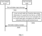
- FIG. 3 is a schematic diagram of signaling interaction in Embodiment 1 of a method for managing an IMSI status of a terminal device according to the present invention.
- This embodiment of the present invention provides a method for managing an IMSI status of a terminal device, where a core network node may be, for example, an MME or an SGSN. As shown in FIG. 3 , the method includes the following steps.
- a first terminal device sends a first activation request message to a core network node.
- the first activation request message carries an IMSI of a second terminal device and an IMSI status indication of the second terminal device.
- the first activation request message is used to request the core network node to set the IMSI of the second terminal device to an activated state or a deactivated state.
- the IMSI status indication is used to indicate that an IMSI status is the activated state or the deactivated state.
- the core network node receives the first activation request message.
- the first activation request message may be implemented by extending an existing attachment/tracking area update (tracking area update, TAU for short) request message, for example, adding a new message field to the attachment/TAU request message to carry information used for IMSI management; or may be implemented by using a newly defined message that is specially used for activation management. This is not limited in this embodiment of the present invention.
- TAU tracking area update
- a communications link is established between the second terminal device and the first terminal device, and IMSI activation or deactivation setting of the second terminal device is implemented by using the first terminal device.
- the smartwatch implements IMSI activation or deactivation setting of the smartwatch by using the smartphone connected to the smartwatch.
- a communications link is established between the smartphone and the smartwatch, and the smartphone and the smartwatch may perform communication by using a technology such as device-to-device (device-to-device, D2D for short)/Bluetooth/Wireless Fidelity (wireless fidelity, Wi-Fi for short).
- the first terminal device and the second terminal device share one user identifier, where the user identifier may be an MSISDN or a public user identity (public user ID, PUI).
- the user identifier may be an MSISDN or a public user identity (public user ID, PUI).
- PUI public user ID
- the MSISDN is a number that a calling user needs to dial to call a mobile subscriber.
- a function of the MSISDN is the same as that of a PSTN number on a rigid network.
- the MSISDN is a number that can uniquely identify a mobile subscriber in a public telephone network switching network numbering plan.
- CC is a country code (country code).
- the country code of China is 86.
- NDC is a national destination code (national destination code), and may also be referred to as a network access number.
- network access numbers of China Mobile are 134 to 139, 150 to 152, or 188
- network access numbers of China Unicom are 130 to 132 or 185 and 186
- network access numbers of China Telecom are 133, 153, 180, or 189.
- SN is a subscriber number (subscriber number).
- a remaining part is a national identity number of a mobile station, that is, a daily used "mobile number”.
- the public user identity is an identification that a user makes public, and is used to communicate with another user. Different public user identities are corresponding to different services of the user.
- the public user identity may be a uniform resource identifier (uniform resource identifier, URI for short).
- the URI is defined by the Request For Comments (Request For Comments, RFC for short) 2396, identifies an abstract resource or a physical resource by using some concise strings, and is used to uniquely identify a specific category of uniform resources.
- a telephone (telephone, TEL for short)-URI and a SIP-URI are two common URIs, and identify a user or a network resource by using a TEL number and a SIP number respectively.
- the TEL-URI identifies a user in a manner of "TEL: user number".
- the user number is defined by using an international public telephone numbering plan: the E.164 format defined by the International Telecommunication Union, namely, a common format of a telephone number or a mobile number.
- E.164 format defined by the International Telecommunication Union, namely, a common format of a telephone number or a mobile number.
- 867711234567 and 8613912345678 are common TEL-URI formats.
- the SIP-URI identifies a user in a manner of "SIP: username@domain name".
- the username may be an all-digit user number, or may be a username starting with a letter.
- sip:7711234567@gx.cn and gx1234567@china.com are common SIP-URI formats.
- the core network node sets, based on subscription information of the second terminal device, the IMSI of the second terminal device to the activated state or the deactivated state, and updates the IMSI status indication of the second terminal device.
- the core network node obtains subscription information of the first terminal device and the subscription information of the second terminal device from an HSS, and stores the subscription information. Therefore, the core network node may locally obtain the subscription information of the second terminal device, or the core network node may obtain the subscription information of the second terminal device from the HSS.
- the core network node after receiving the first activation request message sent by the first terminal device, obtains the subscription information of the second terminal device, where the subscription information includes the IMSI status indication of the second terminal device.
- the IMSI status indication of the second terminal device indicates the activated state or the deactivated state.
- the subscription information may further include a mapping relationship between an IMSI and a user identifier, and herein include an IMSI of the first terminal device and the IMSI of the second terminal device that are mapped to a same user identifier.
- the core network node sets, based on the subscription information of the second terminal device, the IMSI of the second terminal device to the activated state or the deactivated state, and updates the IMSI status indication of the second terminal device.
- the core network node after performing S302, the core network node generates an activation response message.
- the activation response message carries the IMSI of the second terminal device and an updated IMSI status indication of the second terminal device.
- the core network node sends an activation response message to the first terminal device.
- the first terminal device receives the activation response message sent by the core network node.
- the activation response message may be implemented by extending an existing attachment/TAU request message, for example, adding a new message field to the attachment/TAU request message to carry information used for IMSI management; or may be implemented by using a newly defined message that is specially used for activation management. This is not limited in this embodiment of the present invention.
- the core network node receives the first activation request message sent by the first terminal device, where the first activation request message carries the IMSI of the second terminal device and the IMSI status indication of the second terminal device, the first activation request message is used to request the core network node to set the IMSI of the second terminal device to the activated state or the deactivated state, and the IMSI status indication is used to indicate that an IMSI status is the activated state or the deactivated state; sets, based on the subscription information of the second terminal device, the IMSI of the second terminal device to the activated state or the deactivated state, and updates the IMSI status indication of the second terminal device; and finally, sends, to the first terminal device, the activation response message that carries the IMSI of the second terminal device and the updated IMSI status indication of the second terminal device.
- the IMSI of the second terminal device is activated or deactivated through interaction between the first terminal device and the core network node, so that the second terminal device does not participate in activating or deactivating the IMSI of the second terminal device. Therefore, power consumption of the second terminal device can be reduced, and a requirement of an Internet of Things application scenario can be met.
- the wearable device such as a smartwatch
- the mobile phone may replace the smartwatch to implement an IMSI activation process. This can reduce energy consumption of the smartwatch and reduce costs.
- the IMSI of the second terminal device may be activated through interaction between the first terminal device and the core network node. In other words, the IMSI of the first terminal device and the IMSI of the second terminal device may be in the activated state at the same time. In this way, the user requirement of simultaneously using the mobile phone and the smartwatch can be met.
- the setting, by the core network node based on subscription information of the second terminal device, the IMSI of the second terminal device to the activated state or the deactivated state may be specifically: determining, by the core network node, that the IMSI of the second terminal device and an IMSI/IMSIs of one or more terminal devices other than the second terminal device are mapped to a same user identifier, where the user identifier may be an MSISDN or a SIP identifier; obtaining, by the core network node, an IMSI status indication/IMSI status indications of the one or more terminal devices that are mapped to the same user identifier to which the IMSI of the second terminal device is mapped; and determining, by the core network node, to set the IMSI of the second terminal device to the activated state or the deactivated state based on the subscription information of the second terminal device and the IMSI status indication of the terminal device mapped to the same user identifier to which
- the core network node determines an IMSI of another terminal device that shares the same user identifier with the IMSI of the second terminal device, and obtains an IMSI status indication of the another terminal device. For example, the IMSI of the another terminal device is in the activated state and/or the deactivated state, where an IMSI status indication of one terminal device indicates one of the activated state and the deactivated state. Then, the core network node determines to set the IMSI of the second terminal device to the activated state or the deactivated state based on the subscription information of the second terminal device and the IMSI status indication of the another terminal device.
- the first activation request message may further include a service type corresponding to the IMSI of the second terminal device.
- the service type may include at least one of a short message service, voice, data, and the like.
- the core network node can configure, for the second terminal device, the service type corresponding to the IMSI of the second terminal device.
- the first activation request message may further include priority information corresponding to an IMSI of the first terminal device and/or priority information corresponding to the IMSI of the second terminal device.
- the first activation request message may include the priority information corresponding to the IMSI of the first terminal device; or the first activation request message may include the priority information corresponding to the IMSI of the second terminal device; or the first activation request message may include the priority information corresponding to the IMSI of the first terminal device and the priority information corresponding to the IMSI of the second terminal device.
- the priority information corresponding to the IMSI is used to indicate a priority for activating the IMSI.
- an IMSI activation priority of a terminal device is set, so as to implement flexible management on an IMSI of the terminal device.
- the activation response message may also include an updated service type corresponding to the IMSI of the second terminal device and/or updated priority information corresponding to the IMSI of the second terminal device.
- the activation response message may include the updated service type corresponding to the IMSI of the second terminal device; or the activation response message may include the updated priority information corresponding to the IMSI of the second terminal device; or the activation response message may include the updated service type corresponding to the IMSI of the second terminal device and the updated priority information corresponding to the IMSI of the second terminal device.
- the activation response message may further include the IMSI of the first terminal device and an updated IMSI status indication of the first terminal device, and/or an updated service type corresponding to the IMSI of the first terminal device, and/or updated priority information corresponding to the IMSI of the first terminal device.
- the "and/or" means including any one of the foregoing or any combination thereof.
- the activation response message further includes the IMSI of the first terminal device and the updated IMSI status indication of the first terminal device; or the activation response message further includes the updated service type corresponding to the IMSI of the first terminal device; or the activation response message further includes the IMSI of the first terminal device, the updated IMSI status indication of the first terminal device, and the updated priority information corresponding to the IMSI of the first terminal device.
- Other examples are not described herein one by one.
- the first activation request message may further include the IMSI of the first terminal device and an IMSI status indication of the first terminal device.
- the first terminal device can not only activate and deactivate an IMSI of another terminal device (such as the second terminal device), but also activate and deactivate the IMSI of the first terminal device.
- the technical solution can be used to simultaneously activate IMSIs of a plurality of terminal devices (the first terminal device and the second terminal device in this embodiment), where the IMSIs may be corresponding to different service types, so as to meet diversified service requirements.
- the method may further include: determining, by the core network node, that the IMSI of the first terminal device and an IMSI/IMSIs of one or more terminal devices are mapped to a same user identifier, where the user identifier is an MSISDN or a SIP identifier; and when the core network node determines that IMSI statuses of the terminal devices mapped to the user identifier are all set to the deactivated state, determining, based on the subscription information of the second terminal device, to set the IMSI of the second terminal device to the activated state; or when the core network node determines that IMSI statuses of the terminal devices mapped to the user identifier are all set to the deactivated state, determining, based on subscription information of the one or more terminal devices, to set an IMSI
- the method may further include: determining, by the core network node, the IMSI of the first terminal device and/or the IMSI of the second terminal device and an IMSI/IMSIs of one or more terminal devices are mapped to a same user identifier, where the user identifier is an MSISDN or a SIP identifier; and when the core network node determines that IMSI statuses of the terminal devices mapped to the user identifier are all set to the deactivated state, determining, based on subscription information of the first terminal device and the subscription information of the second terminal device, to set the IMSI of the first terminal device to the activated state or to set the IMSI of the second terminal device to the activated state; or when the core network no
- the first activation response message may further include the IMSI of the terminal device that is set to the activated state and that is of the one or more terminal devices and an IMSI status indication of the terminal device that is set to the activated state and that is of the one or more terminal devices.
- the method may further include: sending, by the core network node, a second activation request message to the terminal device that is set to the activated state, where the second activation request message carries the IMSI of the terminal device that is set to the activated state, the IMSI status indication of the terminal device that is set to the activated state, and an updated service type corresponding to the IMSI of the terminal device that is set to the activated state.
- the terminal device receives the second activation request message sent by the core network node, where the second activation request message carries the IMSI of the terminal device and the IMSI status indication of the terminal device, the second activation request message is used to request the terminal device to set the IMSI of the terminal device to the activated state or the deactivated state, and the IMSI status indication is used to indicate that an IMSI status is the activated state or the deactivated state; and sets, based on the second activation request message, the IMSI of the terminal device to the activated state or the deactivated state.
- the second activation request message carries the IMSI of the terminal device and the IMSI status indication of the terminal device
- the second activation request message is used to request the terminal device to set the IMSI of the terminal device to the activated state or the deactivated state
- the IMSI status indication is used to indicate that an IMSI status is the activated state or the deactivated state
- the core network node proactively initiates an IMSI activation or deactivation process, and the terminal device activates or deactivates the IMSI of the terminal device, thereby increasing diversity of IMSI status management of the terminal device.
- the second activation request message may further include a service type corresponding to the IMSI of the terminal device.
- the service type may include at least one of a short message service, voice, data, and the like.
- IMSIs of different terminal devices may be corresponding to different service types, so that diverse service requirements of a user are met.
- a specific process in which the core network node sets, based on the subscription information of the second terminal device, the IMSI of the second terminal device to the activated state or the deactivated state is as follows.
- the core network node determines, based on the subscription information of the second terminal device, whether the IMSI of the second terminal device is allowed to be connected to a network. Only an IMSI of a terminal device that is allowed to be connected to the network can be set to be activated. In addition, if the first activation request message further carries information such as a service or a priority corresponding to the IMSI of the second terminal device, the core network node further needs to determine whether the information is consistent with the subscription information of the second terminal device. If the information is inconsistent with the subscription information of the second terminal device, the first activation request message is rejected, or the information is set based on the subscription information of the second terminal device.
- the core network node further needs to set the IMSI of the second terminal device to the activated state or the deactivated state based on IMSI status indication information of another terminal device that shares a same user identifier with the second terminal device.
- IMSI status indications of the third terminal device may include the following.
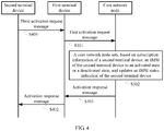
- FIG. 4 is a schematic diagram of signaling interaction in Embodiment 2 of a method for managing an IMSI status of a terminal device according to the present invention. As shown in FIG. 4 , based on the embodiment shown in FIG. 3 , the method may further include the following steps.
- a first terminal device receives a third activation request message sent by a second terminal device.
- the third activation request message carries an IMSI of the second terminal device and an IMSI status indication of the second terminal device.
- the step is performed before S301.
- the first terminal device sends an activation response message to the second terminal device.
- the step is performed after S303.
- the first terminal device may manage IMSIs of all other terminal devices including the second terminal device, and the first terminal device initiates an IMSI activation or deactivation process for the second terminal device, where in the process, the second terminal device does not participate in activating or deactivating the IMSI of the second terminal device; referring to FIG. 4 , the first terminal device may alternatively initiate, upon triggering by the second terminal device, an IMSI activation or deactivation process for the second terminal device.
- the third activation request message in the embodiment shown in FIG. 4 may further include a service type corresponding to the IMSI of the second terminal device.
- the service type includes at least one of a short message service, voice, and data.
- the first activation request message is generated based on the third activation request message.
- the first activation request message and the third activation request message may be the same or may be different, and this is described below.
- the first activation request message may further include an IMSI of the first terminal device and an IMSI status indication of the first terminal device.
- Information carried in the third activation request message all relates to the second terminal device, and the first activation request message further carries information related to the first terminal device. Therefore, the first activation request message and the third activation request message are different in this case.
- the activation response message may further include the IMSI of the first terminal device and an updated IMSI status indication of the first terminal device.
- the method may further include: establishing, by the first terminal device, a communications link with the second terminal device.
- the second terminal device is connected to a network by using the first terminal device.
- a smartwatch is connected to the network by using a mobile phone.
- that the first terminal device sends the first activation request message to the core network node may be triggered by the following conditions.
- Condition 1 Triggered by a user: The first terminal device receives an operation instruction that is entered by the user and that is used to instruct to send the first activation request message. For example, the user may trigger, based on a status change of the user by using an application program, the first terminal device to initiate an IMSI activation/deactivation process.
- the first terminal device Triggered by the first terminal device: The first terminal device generates the first activation request message based on status change information of the first terminal device.
- the status change information may include a battery level change and/or a radio link change, and the like. For example, when detecting that a battery level is low, the smartphone deactivates an IMSI of the smartphone, or changes a service type corresponding to the IMSI of the smartphone from the SMS and voice to the SMS. Other examples are not described herein one by one.
- the first activation request message carries the IMSI status indication of the first terminal device and the IMSI status indication of the second terminal device, description is provided by using the following two cases.
- the method may further include: determining, by the first terminal device, to deactivate the IMSI of the first terminal device; and selecting, by the first terminal device, the second terminal device as a to-be-activated terminal device based on a pre-stored IMSI status indication of a terminal device that is mapped to a same user identifier to which the IMSI of the first terminal device is mapped.
- the IMSI status indication of the second terminal device in the first activation request message indicates the deactivated state
- the IMSI status indication of the first terminal device in the first activation request message indicates the activated state
- the first terminal device is a to-be-activated terminal device that is selected by the second terminal device, after determining to deactivate the IMSI of the second terminal device, based on a pre-stored IMSI status indication of a terminal device that is mapped to a same user identifier to which the IMSI of the second terminal device is mapped.
- execution bodies that select the to-be-activated terminal device are different.
- the first terminal device determines to deactivate the IMSI of the first terminal device, and then selects the second terminal device as the to-be-activated terminal device; and in the second case, the second terminal device determines to deactivate the IMSI of the second terminal device, and then selects the first terminal device as the to-be-activated terminal device.
- the first terminal device can activate/deactivate an IMSI of another terminal device, for example, the IMSI of the second terminal device, is described.
- the following describes a case in which the first terminal device may alternatively activate/deactivate only the IMSI of the first terminal device.
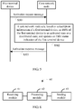
- FIG. 5 is a schematic diagram of signaling interaction in Embodiment 3 of a method for managing an IMSI status of a terminal device according to the present invention. As shown in FIG. 5 , the method includes the following steps.
- a first terminal device sends an activation request message to a core network node.
- the activation request message carries an IMSI of the first terminal device, an IMSI status indication of the first terminal device, and a service type corresponding to the IMSI of the first terminal device.
- the activation request message is used to request the core network node to set the IMSI of the first terminal device to an activated state or a deactivated state.
- the IMSI status indication is used to indicate that an IMSI status is the activated state or the deactivated state, and the service type includes at least one of a short message service, voice, and data.
- the core network node receives the activation request message.
- the core network node sets, based on subscription information of the first terminal device, the IMSI of the first terminal device to the activated state or the deactivated state, and updates the IMSI status indication of the first terminal device.
- the core network node sends an activation response message to the first terminal device.
- the first terminal device receives the activation response message sent by the core network node.
- the activation response message carries the IMSI of the first terminal device, an updated IMSI status indication of the first terminal device, and an updated service type corresponding to the IMSI of the first terminal device. It should be further noted that, the activation response message in the embodiment shown in FIG. 5 is different from the activation response messages in the foregoing embodiments.
- the activation request message carries the service type corresponding to the IMSI of the first terminal device.
- the IMSIs of the all terminal devices may be corresponding to different service types, so that diverse service requirements of a user are met.
- the activation request message may further include priority information corresponding to the IMSI of the first terminal device, so that respective priorities are considered during activation/deactivation of IMSIs of a plurality of terminal devices, and an IMSI of a terminal device with a high priority is preferentially activated. This implements flexible management of IMSI activation/deactivation of the terminal device.
- the method may further include: receiving, by the first terminal device, an operation instruction that is entered by a user and that is used to instruct to send the activation request message; or generating, by the first terminal device, the activation request message based on status change information of the terminal device, where the status change information may include a battery level change and/or a radio link change, and the like.
- the activation response message in the embodiment shown in FIG. 5 may further include an IMSI of a second terminal device and an IMSI status indication of the second terminal device.
- the IMSI status indication of the second terminal device indicates the activated state.
- the second terminal device is a to-be-activated terminal device that is selected by the core network node based on a pre-stored IMSI status indication of a terminal device that is mapped to a same user identifier to which the IMSI of the first terminal device is mapped.
- the core network node selects the second terminal device as the to-be-activated terminal device.
- the program may be stored in a computer-readable storage medium. During execution of the program, steps in the foregoing method embodiments are performed.
- the storage medium includes various media that can store program code, such as a read-only memory (read-only memory, ROM for short), a random access memory (random access memory, RAM for short), a magnetic disk, or an optical disc.
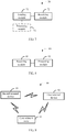
- FIG. 6 is a schematic structural diagram in Embodiment 1 of an apparatus for managing an IMSI status of a terminal device according to the present invention.
- This embodiment of the present invention provides an apparatus for managing an IMSI status of a terminal device, and the apparatus may be integrated into a core network node.
- the core network node may be, for example, an MME or an SGSN.
- the apparatus 60 for managing an IMSI status of a terminal device includes a receiving module 61, a processing module 62, and a sending module 63.
- the receiving module 61 is configured to receive a first activation request message sent by a first terminal device, where the first activation request message carries an IMSI of a second terminal device and an IMSI status indication of the second terminal device, the first activation request message is used to request the core network node to set the IMSI of the second terminal device to an activated state or a deactivated state, and the IMSI status indication is used to indicate that an IMSI status is the activated state or the deactivated state.
- the processing module 62 is configured to: set, based on subscription information of the second terminal device, the IMSI of the second terminal device received by the receiving module 61 to the activated state or the deactivated state, and update the IMSI status indication of the second terminal device.
- the sending module 63 is configured to send an activation response message to the first terminal device, where the activation response message carries the IMSI of the second terminal device and an updated IMSI status indication of the second terminal device obtained by the processing module 62.
- the apparatus in this embodiment may be configured to execute the technical solution executed by the core network node in the foregoing method embodiment, an implementation principle and a technical effect of the apparatus are similar to those of the method embodiment, and details are not described herein again.
- the processing module 62 may be specifically configured to: determine that the IMSI of the second terminal device and an IMSI/IMSIs of one or more terminal devices other than the second terminal device are mapped to a same user identifier, where the user identifier is an MSISDN or a SIP identifier; obtain an IMSI status indication/IMSI status indications of the one or more terminal devices that are mapped to the same user identifier to which the IMSI of the second terminal device is mapped; and set the IMSI of the second terminal device to the activated state or the deactivated state based on the subscription information of the second terminal device and the IMSI status indication of the terminal device mapped to the same user identifier to which the IMSI of the second terminal device is mapped.
- the first activation request message received by the receiving module 61 may further include a service type corresponding to the IMSI of the second terminal device, and the service type may include at least one of a short message service, voice, and data.
- the first activation request message received by the receiving module 61 may further include priority information corresponding to an IMSI of the first terminal device and/or priority information corresponding to the IMSI of the second terminal device.
- the activation response message sent by the sending module 63 may further include an updated service type corresponding to the IMSI of the second terminal device and/or updated priority information corresponding to the IMSI of the second terminal device. Further, the activation response message sent by the sending module 63 may further include the IMSI of the first terminal device and an updated IMSI status indication of the first terminal device, and/or an updated service type corresponding to the IMSI of the first terminal device, and/or updated priority information corresponding to the IMSI of the first terminal device.
- the first activation request message received by the receiving module 61 may further include the IMSI of the first terminal device and an IMSI status indication of the first terminal device.
- the processing module 62 may be further configured to: if the IMSI status indication of the second terminal device in the first activation request message received by the receiving module 61 indicates the deactivated state, determine that the IMSI of the second terminal device and an IMSI/IMSIs of one or more terminal devices are mapped to a same user identifier, where the user identifier is an MSISDN or a SIP identifier; and when it is determined that IMSI statuses of the terminal devices mapped to the user identifier are all set to the deactivated state, determine, based on the subscription information of the second terminal device, to set the IMSI of the second terminal device to the activated state; or if the IMSI status indication of the second terminal device in the first activation request message received by the receiving module 61 indicates the deactivated state, determine that the IMSI of the second terminal device and an IMSI/IMSIs of one or more terminal devices are mapped to a same user identifier, where the user identifier is an M
- the processing module 62 may be further configured to: if the IMSI status indication of the first terminal device and/or the IMSI status indication of the second terminal device in the first activation request message received by the receiving module 61 indicate/indicates the deactivated state, determine that the IMSI of the first terminal device and/or the IMSI of the second terminal device and an IMSI/IMSIs of one or more terminal devices are mapped to a same user identifier, where the user identifier is an MSISDN or a SIP identifier; and when it is determined that IMSI statuses of the terminal devices mapped to the user identifier are all set to the deactivated state, determine, based on subscription information of the first terminal device and the subscription information of the second terminal device, to set the IMSI of the first terminal device to the activated state or to set the IMSI of the second terminal device to the activated state; or if the IMSI status indication of the first terminal device and/or the IMSI status indication of the second terminal device
- the first activation response message received by the receiving module 61 may further include the IMSI of the terminal device that is set to the activated state and that is of the one or more terminal devices and an IMSI status indication of the terminal device that is set to the activated state and that is of the one or more terminal devices.
- the sending module 63 may be further configured to send a second activation request message to the terminal device that is set to the activated state, where the second activation request message carries the IMSI of the terminal device that is set to the activated state, the IMSI status indication of the terminal device that is set to the activated state, and an updated service type corresponding to the IMSI of the terminal device that is set to the activated state.
- FIG. 7 is a schematic structural diagram in Embodiment 2 of an apparatus for managing an IMSI status of a terminal device according to the present invention.
- This embodiment of the present invention provides an apparatus for managing an IMSI status of a terminal device, and the apparatus may be integrated into a first terminal device.
- the apparatus 70 for managing an IMSI status of a terminal device includes a sending module 71 and a receiving module 72.
- the sending module 71 is configured to send a first activation request message to a core network node, where the first activation request message carries an IMSI of a second terminal device and an IMSI status indication of the second terminal device, the first activation request message is used to request the core network node to set the IMSI of the second terminal device to an activated state or a deactivated state, and the IMSI status indication is used to indicate that an IMSI status is the activated state or the deactivated state.
- the receiving module 72 is configured to receive an activation response message sent by the core network node, where the activation response message carries the IMSI of the second terminal device and an updated IMSI status indication of the second terminal device, and the updated IMSI status indication of the second terminal device is an IMSI status indication of the second terminal device that is updated after the core network node sets, based on subscription information of the second terminal device, the IMSI of the second terminal device to the activated state or the deactivated state.
- the apparatus in this embodiment may be configured to execute the technical solution executed by the first terminal device in the foregoing method embodiment, an implementation principle and a technical effect of the apparatus are similar to those of the method embodiment, and details are not described herein again.
- the receiving module 72 may be further configured to: before the sending module 71 sends the first activation request message to the core network node, receive a third activation request message sent by the second terminal device, where the third activation request message carries the IMSI of the second terminal device and the IMSI status indication of the second terminal device.
- the sending module 71 may be further configured to: after the receiving module 72 receives the activation response message sent by the core network node, send the activation response message to the second terminal device.
- the third activation request message received by the receiving module 72 may further include a service type corresponding to the IMSI of the second terminal device, and the service type includes at least one of a short message service, voice, and data.
- the first activation request message sent by the sending module 71 is generated based on the third activation request message received by the receiving module 72.
- the first activation request message sent by the sending module 71 may further include an IMSI of the first terminal device and an IMSI status indication of the first terminal device.
- the activation response message received by the receiving module 72 may further include the IMSI of the first terminal device and the IMSI status indication of the first terminal device.
- the first activation request message sent by the sending module 71 may further include a service type corresponding to the IMSI of the first terminal device, and the service type includes at least one of a short message service, voice, and data.
- the first activation request message sent by the sending module 71 may further include priority information corresponding to the IMSI of the first terminal device and/or priority information corresponding to the IMSI of the second terminal device.
- the activation response message received by the receiving module 72 may further include at least one of an updated service type corresponding to the IMSI of the second terminal device, updated priority information corresponding to the IMSI of the second terminal device, an updated service type corresponding to the IMSI of the first terminal device, and updated priority information corresponding to the IMSI of the first terminal device.
- the apparatus 70 for managing an IMSI status of a terminal device may further include a processing module 73.
- the processing module 73 is configured to: before the sending module 71 sends the first activation request message to the core network node, establish a communications link with the second terminal device, so that the second terminal device is connected to a network by using the first terminal device.
- the processing module 73 may be further configured to generate the first activation request message based on status change information of the first terminal device, where the status change information may include a battery level change and/or a radio link change, and the like.
- the receiving module 72 may be further configured to: before the sending module 71 sends the first activation request message to the core network node, receive an operation instruction that is entered by a user and that is used to instruct to send the first activation request message.
- the processing module 73 may be further configured to: when the IMSI status indication of the first terminal device in the first activation request message sent by the sending module 71 indicates the deactivated state, and the IMSI status indication of the second terminal device in the first activation request message sent by the sending module 71 indicates the activated state, before the sending module 71 sends the first activation request message to the core network node, determine to deactivate the IMSI of the first terminal device; and select the second terminal device as a to-be-activated terminal device based on a pre-stored IMSI status indication of a terminal device that is mapped to a same user identifier to which the IMSI of the first terminal device is mapped, where the user identifier is an MSISDN or a SIP identifier.
- the first terminal device is a to-be-activated terminal device that is selected by the second terminal device, after determining to deactivate the IMSI of the second terminal device, based on a pre-stored IMSI status indication of a terminal device that is mapped to a same user identifier to which the IMSI of the second terminal device is mapped, where the user identifier is an MSISDN or a SIP identifier.
- Embodiment 8 is a schematic structural diagram in Embodiment 3 of an apparatus for managing an IMSI status of a terminal device according to the present invention.
- This embodiment of the present invention provides an apparatus for managing an IMSI status of a terminal device, and the apparatus may be integrated into the terminal device.
- the apparatus 80 for managing an IMSI status of a terminal device includes a receiving module 81 and a processing module 82.
- the receiving module 81 is configured to receive a second activation request message sent by a core network node, where the second activation request message carries an IMSI of the terminal device and an IMSI status indication of the terminal device, the second activation request message is used to request the terminal device to set the IMSI of the terminal device to an activated state or a deactivated state, the terminal device is a terminal device that is set to the activated state and that is determined by the core network node based on an IMSI status indication carried in a first activation request message sent by a first terminal device, and the IMSI status indication is used to indicate that an IMSI status is the activated state or the deactivated state.
- the processing module 82 is configured to set the IMSI of the terminal device to the activated state or the deactivated state based on the IMSI status indication of the terminal device in the second activation request message received by the receiving module 81.
- the apparatus in this embodiment may be configured to execute the technical solution executed by the terminal device that is set to the activated state in the foregoing method embodiment, an implementation principle and a technical effect of the apparatus are similar to those of the method embodiment, and details are not described herein again.
- the second activation request message received by the receiving module 81 may further include a service type corresponding to the IMSI of the terminal device, and the service type includes at least one of a short message service, voice, and data.
- functions of the processing module may be specifically implemented by a processor in a corresponding terminal device or core network node
- functions of the sending module may be specifically implemented by a transmitter in a corresponding terminal device or core network node
- functions of the receiving module may be specifically implemented by a receiver in a corresponding terminal device or core network node.
- the transmitter and the receiver may be separately and independently disposed, or may be integrated into a transceiver. This is not limited in this embodiment of the present invention.
- FIG. 9 is a schematic structural diagram in Embodiment 1 of a system for managing an IMSI status of a terminal device according to the present invention.
- the system 90 for managing an IMSI status of a terminal device includes a core network node 91, a first terminal device 92, and a second terminal device 93.
- the core network node 91 includes the apparatus shown in FIG. 6
- the first terminal device includes the apparatus shown in FIG. 7
- both the first terminal device 92 and the second terminal device 93 include the apparatus shown in FIG. 8 .
- the disclosed apparatus and method may be implemented in other manners.
- the described apparatus embodiment is merely an example.
- the unit division is merely logical function division and may be other division in actual implementation.
- a plurality of units or components may be combined or may be integrated into another system, or some features may be ignored or not performed.
- the displayed or discussed mutual couplings or direct couplings or communication connections may be implemented by using some interfaces.
- the indirect couplings or communication connections between the apparatuses or units may be implemented in electrical, mechanical, or other forms.
- the units described as separate parts may or may not be physically separate, and parts displayed as units may or may not be physical units, may be located in one position, or may be distributed on a plurality of network units. Some or all of the units may be selected depending on an actual requirement, to achieve the objectives of the solutions of the embodiments.
- functional units in the embodiments of the present invention may be integrated into one processing unit, or each of the units may exist alone physically, or two or more units may be integrated into one unit.
- the integrated unit may be implemented in a form of hardware, or may be implemented in a form of hardware in addition to a software function unit.
- the integrated unit may be stored in a computer-readable storage medium.
- the software function unit is stored in a storage medium and includes several instructions for instructing a computer device (which may be a personal computer, a server, a network device, or the like) or a processor (processor) to perform some of the steps of the methods described in the embodiments of the present invention.
- the foregoing storage medium includes various media that can store program code, such as a USB flash drive, a removable hard disk, a ROM, a RAM, a magnetic disk, or an optical disc.
Landscapes
- Engineering & Computer Science (AREA)
- Computer Networks & Wireless Communication (AREA)
- Signal Processing (AREA)
- Databases & Information Systems (AREA)
- Mobile Radio Communication Systems (AREA)
- Telephone Function (AREA)
Claims (11)
- Verfahren zum Verwalten eines Status der "International Mobile Subscriber Identity" IMSI einer Endgerätevorrichtung, umfassend:Empfangen (S301) einer durch eine erste Endgerätevorrichtung gesendeten ersten Aktivierungsanforderungsnachricht durch einen Kernnetzknoten, wobei die erste Aktivierungsanforderungsnachricht eine IMSI einer zweiten Endgerätevorrichtung und eine IMSI-Statusangabe der zweiten Endgerätevorrichtung führt, die erste Aktivierungsanforderungsnachricht verwendet wird, um von dem Kernnetzknoten anzufordern, die IMSI der zweiten Endgerätevorrichtung auf einen Deaktiviert-Zustand zu setzen, und die IMSI-Statusangabe verwendet wird, um anzugeben, dass ein IMSI-Status der Deaktiviert-Zustand ist;Setzen (S302) der IMSI der zweiten Endgerätevorrichtung auf dem Deaktiviert-Zustand durch den Kernnetzknoten auf der Basis von Subskriptionsinformationen der zweiten Endgerätevorrichtung und Aktualisieren der IMSI-Statusangabe der zweiten Endgerätevorrichtung; undSenden (S303) einer Aktivierungsantwortnachricht zu der ersten Endgerätevorrichtung durch den Kernnetzknoten, wobei die Aktivierungsantwortnachricht die IMSI der zweiten Endgerätevorrichtung und eine aktualisierte IMSI-Statusangabe der zweiten Endgerätevorrichtung führt.
- Verfahren nach Anspruch 1, wobei das Setzen (S302) der IMSI der zweiten Endgerätevorrichtung auf den Deaktiviert-Zustand durch den Kernnetzknoten auf der Basis von Subskriptionsinformationen der zweiten Endgerätevorrichtung Folgendes umfasst:Bestimmen durch den Kernnetzknoten, dass die IMSI der zweiten Endgerätevorrichtung und eine IMSI/IMSIs einer oder mehrerer Endgerätevorrichtungen außer der zweiten Endgerätevorrichtung auf eine selbe Benutzerkennung abgebildet werden, wobei die Benutzerkennung eine "Mobile Subscriber International ISDN/PSTN"-Nummer MSISDN oder eine Kennung des "Session Initiation Protocol" SIP ist;Erhalten einer IMSI-Statusangabe/von IMSI-Statusangaben der einen oder mehreren Endgerätevorrichtungen, die auf dieselbe Benutzerkennung abgebildet werden, auf die die IMSI der zweiten Endgerätevorrichtung abgebildet wird, durch den Kernnetzknoten; undSetzen der IMSI der zweiten Endgerätevorrichtung auf den Deaktiviert-Zustand durch den Kernnetzknoten auf der Basis der Subskriptionsinformationen der zweiten Endgerätevorrichtung und der IMSI-Statusangabe der Endgerätevorrichtung, die auf dieselbe Benutzerkennung abgebildet wird, auf die die IMSI der zweiten Endgerätevorrichtung abgebildet wird.
- Verfahren nach Anspruch 1 oder 2, wobei die erste Aktivierungsanforderungsnachricht ferner einen der IMSI der zweiten Endgerätevorrichtung entsprechenden Diensttyp umfasst und der Diensttyp mindestens einen von "Short Message Service", Sprache und Daten umfasst.
- Vorrichtung (60) zum Verwalten eines Status der "International Mobile Subscriber Identity" IMSI einer Endgerätevorrichtung, wobei die Vorrichtung (60) in einem Kernnetzknoten integriert ist und die Vorrichtung (60) Folgendes umfasst:ein Empfangsmodul (61), ausgelegt zum Empfangen einer durch eine erste Endgerätevorrichtung gesendeten ersten Aktivierungsanforderungsnachricht, wobei die erste Aktivierungsanforderungsnachricht eine IMSI einer zweiten Endgerätevorrichtung und einer IMSI-Statusangabe der zweiten Endgerätevorrichtung führt, die erste Aktivierungsanforderungsnachricht verwendet wird, um von dem Kernnetzknoten anzufordern, die IMSI der zweiten Endgerätevorrichtung auf einen Deaktiviert-Zustand zu setzen, und die IMSI-Statusangabe verwendet wird, um anzugeben, dass ein IMSI-Status der Deaktiviert-Zustand ist;ein Verarbeitungsmodul (62) ausgelegt zum Setzen der IMSI der durch das Empfangsmodul empfangenen zweiten Endgerätevorrichtung auf den Deaktiviert-Zustand auf der Basis von Subskriptionsinformationen der zweiten Endgerätevorrichtung und Aktualisieren der IMSI-Statusangabe der zweiten Endgerätevorrichtung; undein Sendemodul (63), ausgelegt zum Senden einer Aktivierungsantwortnachricht zu der ersten Endgerätevorrichtung, wobei die Aktivierungsantwortnachricht die IMSI der zweiten Endgerätevorrichtung und eine aktualisierte IMSI-Statusangabe der zweiten Endgerätevorrichtung, die durch das Verarbeitungsmodul erhalten wird, führt.
- Vorrichtung (60) nach Anspruch 4, wobei das Verarbeitungsmodul (62) speziell ausgelegt ist zum
Bestimmen dass die IMSI der zweiten Endgerätevorrichtung und eine IMSI/IMSIs einer oder mehrerer Endgerätevorrichtungen außer der zweiten Endgerätevorrichtung auf eine selbe Benutzerkennung abgebildet werden, wobei die Benutzerkennung eine "Mobile Subscriber International ISDN/PSTN"-Nummer MSISDN oder eine Kennung des "Session Initiation Protocol" SIP ist;
Erhalten einer IMSI-Statusangabe/von IMSI-Statusangaben der einen oder mehreren Endgerätevorrichtungen, die auf dieselbe Benutzerkennung abgebildet werden, auf die die IMSI der zweiten Endgerätevorrichtung abgebildet wird; und
Setzen der IMSI der zweiten Endgerätevorrichtung auf den Deaktiviert-Zustand auf der Basis der Subskriptionsinformationen der zweiten Endgerätevorrichtung und der IMSI-Statusangabe der Endgerätevorrichtung, die auf dieselbe Benutzerkennung abgebildet wird, auf die die IMSI der zweiten Endgerätevorrichtung abgebildet wird. - Vorrichtung (60) nach Anspruch 4 oder 5, wobei die durch das Empfangsmodul (61) empfangene erste Aktivierungsanforderungsnachricht ferner einen der IMSI der zweiten Endgerätevorrichtung entsprechenden Diensttyp umfasst und der Diensttyp mindestens einen von "Short Message Service", Sprache und Daten umfasst.
- Vorrichtung (70) zum Verwalten eines Status der "International Mobile Subscriber Identity" IMSI einer Endgerätevorrichtung, wobei die Vorrichtung (70) in eine erste Endgerätevorrichtung integriert ist und die Vorrichtung (70) Folgendes umfasst:ein Sendemodul (71), ausgelegt zum Senden einer ersten Aktivierungsanforderungsnachricht zu einem Kernnetzknoten, wobei die erste Aktivierungsanforderungsnachricht eine IMSI einer zweiten Endgerätevorrichtung und eine IMSI-Statusangabe der zweiten Endgerätevorrichtung führt, die erste Aktivierungsanforderungsnachricht verwendet wird, um von dem Kernnetzknoten anzufordern, die IMSI der zweiten Endgerätevorrichtung auf einen Deaktiviert-Zustand zu setzen, und die IMSI-Statusangabe verwendet wird, um anzugeben, dass ein IMSI-Status der Deaktiviert-Zustand ist;ein Empfangsmodul (72), ausgelegt zum Empfangen einer durch den Kernnetzknoten gesendeten Aktivierungsantwortnachricht, wobei die Aktivierungsantwortnachricht die IMSI der zweiten Endgerätevorrichtung und eine aktualisierte IMSI-Statusangabe der zweiten Endgerätevorrichtung führt und die aktualisierte IMSI-Statusangabe der zweiten Endgerätevorrichtung eine IMSI-Statusangabe der zweiten Endgerätevorrichtung ist, die aktualisiert wird, nachdem der Kernnetzknoten auf der Basis von Subskriptionsinformationen der zweiten Endgerätevorrichtung die IMSI der zweiten Endgerätevorrichtung auf den Deaktiviert-Zustand setzt.
- Vorrichtung (70) nach Anspruch 7, wobei das Empfangsmodul (72) ferner ausgelegt ist zum
Empfangen einer durch die zweite Endgerätevorrichtung gesendeten dritten Aktivierungsanforderungsnachricht, bevor das Sendemodul (71) die erste Aktivierungsanforderungsnachricht zu dem Kernnetzknoten sendet, wobei die dritte Aktivierungsanforderungsnachricht die IMSI der zweiten Endgerätevorrichtung und die IMSI-Statusangabe der zweiten Endgerätevorrichtung führt; und
das Sendemodul (71) entsprechend ferner ausgelegt ist zum Senden der Aktivierungsantwortnachricht zu der zweiten Endgerätevorrichtung, nachdem das Empfangsmodul die durch den Kernnetzknoten gesendete Aktivierungsantwortnachricht empfängt. - Vorrichtung (70) nach Anspruch 8, wobei die durch das Empfangsmodul (72) empfangene dritte Aktivierungsanforderungsnachricht ferner einen der IMSI der zweiten Endgerätevorrichtung entsprechenden Diensttyp umfasst und der Diensttyp mindestens einen von "Short Message Service", Sprache und Daten umfasst.
- Vorrichtung (70) nach Anspruch 8 oder 9, wobei die durch das Sendemodul (71) gesendete erste Aktivierungsanforderungsnachricht auf der Basis der durch das Empfangsmodul (72) empfangenen dritten Aktivierungsanforderungsnachricht erzeugt wird.
- Vorrichtung (70) nach einem der Ansprüche 7 bis 10, wobei die durch das Sendemodul (71) gesendete erste Aktivierungsanforderungsnachricht ferner eine IMSI der ersten Endgerätevorrichtung und eine IMSI-Statusangabe der ersten Endgerätevorrichtung umfasst; und
die durch das Empfangsmodul (72) empfangene Aktivierungsantwortnachricht entsprechend ferner die IMSI der ersten Endgerätevorrichtung und die IMSI-Statusangabe der ersten Endgerätevorrichtung umfasst.
Applications Claiming Priority (1)
| Application Number | Priority Date | Filing Date | Title |
|---|---|---|---|
| PCT/CN2016/088296 WO2018006215A1 (zh) | 2016-07-04 | 2016-07-04 | 管理终端设备的imsi状态的方法、装置及系统 |
Publications (3)
| Publication Number | Publication Date |
|---|---|
| EP3468239A4 EP3468239A4 (de) | 2019-04-10 |
| EP3468239A1 EP3468239A1 (de) | 2019-04-10 |
| EP3468239B1 true EP3468239B1 (de) | 2020-02-05 |
Family
ID=60901253
Family Applications (1)
| Application Number | Title | Priority Date | Filing Date |
|---|---|---|---|
| EP16907724.5A Active EP3468239B1 (de) | 2016-07-04 | 2016-07-04 | Verfahren und vorrichtung zur verwaltung des imsi-zustands einer endgerätevorrichtung |
Country Status (4)
| Country | Link |
|---|---|
| US (1) | US10623945B2 (de) |
| EP (1) | EP3468239B1 (de) |
| CN (1) | CN109314857B (de) |
| WO (1) | WO2018006215A1 (de) |
Families Citing this family (12)
| Publication number | Priority date | Publication date | Assignee | Title |
|---|---|---|---|---|
| US9247399B2 (en) | 2013-03-14 | 2016-01-26 | Google Technology Holdings LLC | Alert peripheral for notification of events occuring on a programmable user equipment with communication capabilities |
| EP3468239B1 (de) * | 2016-07-04 | 2020-02-05 | Huawei Technologies Co., Ltd. | Verfahren und vorrichtung zur verwaltung des imsi-zustands einer endgerätevorrichtung |
| KR102484367B1 (ko) * | 2016-09-09 | 2023-01-04 | 삼성전자주식회사 | UICC와 eUICC의 제어 방법 및 시스템 |
| US11516649B2 (en) * | 2018-10-29 | 2022-11-29 | Apple Inc. | Mechanism to activate and manage a standalone device for cellular service |
| US10764732B1 (en) | 2019-09-30 | 2020-09-01 | At&T Intellectual Property I, L.P. | Methods, systems, and devices for providing subscription services for a communication device using an operational profile |
| US10856121B1 (en) * | 2019-10-22 | 2020-12-01 | At&T Intellectual Property I, L.P. | Methods, systems, and devices for providing subscription services to a communication device that shares an operational profile with another communication device |
| US10834574B1 (en) | 2019-11-04 | 2020-11-10 | At&T Intellectual Property I, L.P. | Methods, systems, and devices for obtaining a profile enabling establishment of an active subscription for services of a mobile network |
| US11159927B2 (en) | 2019-11-04 | 2021-10-26 | At&T Intellectual Property I, L.P. | Methods, systems, and devices for establishing an active subscription for services of a mobile network |
| US11381658B2 (en) | 2019-11-08 | 2022-07-05 | At&T Intellectual Property I, L.P. | Managing devices through use of blocks of operational profiles |
| US11979924B2 (en) | 2021-02-25 | 2024-05-07 | Charter Communications Operating, Llc | Device address bundling for IoT communication |
| CN114374967B (zh) * | 2021-12-30 | 2023-12-12 | 天翼物联科技有限公司 | 一号多终端配置方法、系统及装置 |
| CN121399986A (zh) * | 2023-06-29 | 2026-01-23 | 瑞典爱立信有限公司 | 用于向应用功能的用户设备域信息开放的方法和装置 |
Family Cites Families (37)
| Publication number | Priority date | Publication date | Assignee | Title |
|---|---|---|---|---|
| US5887253A (en) * | 1996-03-22 | 1999-03-23 | Bellsouth Corporation | Method for activating and servicing a cellular telephone |
| FI104139B1 (fi) | 1996-11-27 | 1999-11-15 | Nokia Telecommunications Oy | Kahden SIM-kortin käyttäminen samalla MSISDN-numerolla |
| US9307397B2 (en) * | 2005-04-29 | 2016-04-05 | Jasper Technologies, Inc. | Method for enabling a wireless device with customer-specific services |
| CN100388685C (zh) * | 2005-08-30 | 2008-05-14 | 华为技术有限公司 | Ip多媒体子系统中ims注册触发实现方法 |
| CN101325592B (zh) * | 2007-06-14 | 2011-04-20 | 华为技术有限公司 | 一种建立承载连接的方法、装置及系统 |
| CN101123748B (zh) * | 2007-06-25 | 2011-02-02 | 华为技术有限公司 | 一种提示用户进行激活操作的方法及系统、装置 |
| CN101355792B (zh) * | 2007-07-25 | 2011-11-23 | 华为技术有限公司 | 承载删除控制方法及归属用户服务器以及相关设备 |
| CN101378591B (zh) * | 2007-08-31 | 2010-10-27 | 华为技术有限公司 | 终端移动时安全能力协商的方法、系统及装置 |
| CN101399767B (zh) * | 2007-09-29 | 2011-04-20 | 华为技术有限公司 | 终端移动时安全能力协商的方法、系统及装置 |
| EP2196048B1 (de) * | 2007-10-05 | 2014-11-19 | Telefonaktiebolaget LM Ericsson (publ) | Endgeräte-trace-aktivierung in einem drahtlosen kommunikationsnetz |
| DE102008024798A1 (de) * | 2008-05-23 | 2009-12-17 | T-Mobile International Ag | Verfahren zur Over-The-Air Personalisierung von Chipkarten in der Telekommunikation |
| CN102711276B (zh) * | 2008-06-13 | 2015-12-02 | 上海华为技术有限公司 | 一种数据通讯方法及通讯系统以及相关装置 |
| CN101400186B (zh) * | 2008-11-05 | 2010-06-09 | 中国移动通信集团江苏有限公司 | 一种在移动通信系统中实现一号双卡的方法 |
| US9955332B2 (en) * | 2009-01-28 | 2018-04-24 | Headwater Research Llc | Method for child wireless device activation to subscriber account of a master wireless device |
| US9557889B2 (en) * | 2009-01-28 | 2017-01-31 | Headwater Partners I Llc | Service plan design, user interfaces, application programming interfaces, and device management |
| CN101998331B (zh) * | 2009-08-21 | 2013-08-07 | 电信科学技术研究院 | 用户设备注册状态的识别方法和设备 |
| CN102076124B (zh) * | 2009-11-19 | 2014-04-09 | 中兴通讯股份有限公司 | 一种变更签约数据的系统、方法及设备 |
| CN101771692B (zh) * | 2009-12-30 | 2013-01-30 | 华为终端有限公司 | 一种用户终端设备区域管理的方法、装置及系统 |
| US8417221B2 (en) * | 2010-06-08 | 2013-04-09 | At&T Intellectual Property I, L.P. | Interactive personalized e-experience system and method for visual voice mail |
| CN102143447B (zh) * | 2010-12-31 | 2014-04-16 | 华为技术有限公司 | 一卡多号业务处理方法和系统及一卡多号平台 |
| CN103037347A (zh) * | 2011-09-29 | 2013-04-10 | 中兴通讯股份有限公司 | 机器类型通信终端的激活方法、装置及系统 |
| WO2014198056A1 (zh) * | 2013-06-14 | 2014-12-18 | 华为技术有限公司 | 小区发现方法及装置 |
| CN104704867B (zh) * | 2013-08-15 | 2018-10-30 | 华为技术有限公司 | 数据路由的方法和设备 |
| CN103619053B (zh) * | 2013-11-08 | 2018-03-30 | 苏州安可信通信技术有限公司 | 一种用户识别卡的使用方法和通信系统 |
| WO2015168945A1 (zh) * | 2014-05-09 | 2015-11-12 | 华为技术有限公司 | D2d发现信息的接收方法和装置 |
| US9686668B2 (en) * | 2014-05-30 | 2017-06-20 | Vonage America Inc. | Method and apparatus for intra-network roaming for IP telephony network |
| CN105393576B (zh) * | 2014-06-20 | 2020-05-15 | 上海朋邦实业有限公司 | 一种数据传输方法及设备 |
| FR3018985A1 (fr) * | 2014-06-20 | 2015-09-25 | Orange | Procede d'activation d'une carte d'abonne de type carte sim |
| GB2530268A (en) * | 2014-09-16 | 2016-03-23 | Eseye Ltd | Sim card activation |
| US9848284B2 (en) * | 2014-09-24 | 2017-12-19 | Stmicroelectronics, Inc. | Portable mobile subscription |
| CN105530632A (zh) * | 2014-09-29 | 2016-04-27 | 中兴通讯股份有限公司 | 一号多卡实现方法、装置、归属位置寄存器及通信系统 |
| KR101952227B1 (ko) * | 2015-02-17 | 2019-05-20 | 후아웨이 테크놀러지 컴퍼니 리미티드 | 백홀 링크 구축 방법, 기지국 및 장치 |
| US9571664B2 (en) * | 2015-05-22 | 2017-02-14 | Verizon Patent And Licensing Inc. | Reliable activation of mobile devices |
| CN105050071B (zh) * | 2015-07-10 | 2019-09-24 | 惠州Tcl移动通信有限公司 | 一种基于eUICC的多设备管理方法及系统 |
| US10425884B2 (en) * | 2015-09-14 | 2019-09-24 | Lg Electronics Inc. | Method for setting up bearer in wireless communication system and apparatus supporting same |
| EP3468239B1 (de) * | 2016-07-04 | 2020-02-05 | Huawei Technologies Co., Ltd. | Verfahren und vorrichtung zur verwaltung des imsi-zustands einer endgerätevorrichtung |
| US10200852B1 (en) * | 2017-08-24 | 2019-02-05 | Syniverse Technologies, Llc | Method and system of enabling roaming services in a data-only network to a user equipment requiring a dual attachment to packet and circuit switched networks |
-
2016
- 2016-07-04 EP EP16907724.5A patent/EP3468239B1/de active Active
- 2016-07-04 WO PCT/CN2016/088296 patent/WO2018006215A1/zh not_active Ceased
- 2016-07-04 CN CN201680086842.0A patent/CN109314857B/zh active Active
-
2019
- 2019-01-03 US US16/239,426 patent/US10623945B2/en active Active
Non-Patent Citations (1)
| Title |
|---|
| None * |
Also Published As
| Publication number | Publication date |
|---|---|
| US20190141518A1 (en) | 2019-05-09 |
| EP3468239A4 (de) | 2019-04-10 |
| EP3468239A1 (de) | 2019-04-10 |
| WO2018006215A1 (zh) | 2018-01-11 |
| CN109314857A (zh) | 2019-02-05 |
| US10623945B2 (en) | 2020-04-14 |
| CN109314857B (zh) | 2020-09-29 |
Similar Documents
| Publication | Publication Date | Title |
|---|---|---|
| EP3468239B1 (de) | Verfahren und vorrichtung zur verwaltung des imsi-zustands einer endgerätevorrichtung | |
| US12302189B2 (en) | Registration management method for terminal accessing 5G network on non-3GPP access | |
| CN115039425B (zh) | 通过使用情况监控事件扩展Npcf_EventExposure | |
| US11134103B2 (en) | Method of enabling slice security separation | |
| CN112637947B (zh) | 基站、接入和移动性管理功能实体及其方法 | |
| JP6260540B2 (ja) | 無線通信システム、無線アクセスネットワークノード、及び通信デバイス | |
| RU2743579C2 (ru) | Способ подключения носимых устройств | |
| KR20200110792A (ko) | Pdu 세션 업데이트 방법 및 네트워크측 기기 | |
| CN105684511A (zh) | 从移动无线电通信设备的数据传输 | |
| JP7175745B2 (ja) | 複数のsimを搭載した端末と通信設備装置とを有するシステム | |
| JP5961713B1 (ja) | 通信システム | |
| JP2017038323A (ja) | 基地局、管理装置及び接続方法 | |
| CN116264721B (zh) | 小区切换方法及设备 | |
| JP6498168B2 (ja) | 通信端末装置 | |
| JP6387268B2 (ja) | 通信制御装置、通信制御システム、及び通信制御方法 | |
| JP2015501105A (ja) | 無線通信システムでショートメッセージサービスを効率的に伝達する方法及びシステム | |
| JP2015115767A (ja) | 移動通信システム、移動局、ネットワーク装置及び移動通信方法 | |
| WO2014161104A1 (en) | Method and apparatus for charging device to device traffic | |
| JP2018056671A (ja) | 通信端末装置 | |
| JP2018133606A (ja) | 通信システム、通信端末、制御装置、通信制御方法および通信プログラム |
Legal Events
| Date | Code | Title | Description |
|---|---|---|---|
| STAA | Information on the status of an ep patent application or granted ep patent |
Free format text: STATUS: THE INTERNATIONAL PUBLICATION HAS BEEN MADE |
|
| PUAI | Public reference made under article 153(3) epc to a published international application that has entered the european phase |
Free format text: ORIGINAL CODE: 0009012 |
|
| STAA | Information on the status of an ep patent application or granted ep patent |
Free format text: STATUS: REQUEST FOR EXAMINATION WAS MADE |
|
| 17P | Request for examination filed |
Effective date: 20190107 |
|
| A4 | Supplementary search report drawn up and despatched |
Effective date: 20190308 |
|
| AK | Designated contracting states |
Kind code of ref document: A1 Designated state(s): AL AT BE BG CH CY CZ DE DK EE ES FI FR GB GR HR HU IE IS IT LI LT LU LV MC MK MT NL NO PL PT RO RS SE SI SK SM TR |
|
| AX | Request for extension of the european patent |
Extension state: BA ME |
|
| GRAP | Despatch of communication of intention to grant a patent |
Free format text: ORIGINAL CODE: EPIDOSNIGR1 |
|
| STAA | Information on the status of an ep patent application or granted ep patent |
Free format text: STATUS: GRANT OF PATENT IS INTENDED |
|
| RIC1 | Information provided on ipc code assigned before grant |
Ipc: H04W 8/24 20090101AFI20190828BHEP Ipc: H04W 52/02 20090101ALN20190828BHEP |
|
| DAV | Request for validation of the european patent (deleted) | ||
| DAX | Request for extension of the european patent (deleted) | ||
| RIC1 | Information provided on ipc code assigned before grant |
Ipc: H04W 52/02 20090101ALN20190830BHEP Ipc: H04W 8/24 20090101AFI20190830BHEP |
|
| INTG | Intention to grant announced |
Effective date: 20190920 |
|
| RIC1 | Information provided on ipc code assigned before grant |
Ipc: H04W 52/02 20090101ALN20190910BHEP Ipc: H04W 8/24 20090101AFI20190910BHEP |
|
| GRAS | Grant fee paid |
Free format text: ORIGINAL CODE: EPIDOSNIGR3 |
|
| GRAA | (expected) grant |
Free format text: ORIGINAL CODE: 0009210 |
|
| STAA | Information on the status of an ep patent application or granted ep patent |
Free format text: STATUS: THE PATENT HAS BEEN GRANTED |
|
| AK | Designated contracting states |
Kind code of ref document: B1 Designated state(s): AL AT BE BG CH CY CZ DE DK EE ES FI FR GB GR HR HU IE IS IT LI LT LU LV MC MK MT NL NO PL PT RO RS SE SI SK SM TR |
|
| REG | Reference to a national code |
Ref country code: GB Ref legal event code: FG4D |
|
| REG | Reference to a national code |
Ref country code: AT Ref legal event code: REF Ref document number: 1230779 Country of ref document: AT Kind code of ref document: T Effective date: 20200215 |
|
| REG | Reference to a national code |
Ref country code: DE Ref legal event code: R096 Ref document number: 602016029332 Country of ref document: DE |
|
| REG | Reference to a national code |
Ref country code: IE Ref legal event code: FG4D |
|
| REG | Reference to a national code |
Ref country code: CH Ref legal event code: EP |
|
| REG | Reference to a national code |
Ref country code: NL Ref legal event code: FP |
|
| PG25 | Lapsed in a contracting state [announced via postgrant information from national office to epo] |
Ref country code: NO Free format text: LAPSE BECAUSE OF FAILURE TO SUBMIT A TRANSLATION OF THE DESCRIPTION OR TO PAY THE FEE WITHIN THE PRESCRIBED TIME-LIMIT Effective date: 20200505 Ref country code: FI Free format text: LAPSE BECAUSE OF FAILURE TO SUBMIT A TRANSLATION OF THE DESCRIPTION OR TO PAY THE FEE WITHIN THE PRESCRIBED TIME-LIMIT Effective date: 20200205 Ref country code: PT Free format text: LAPSE BECAUSE OF FAILURE TO SUBMIT A TRANSLATION OF THE DESCRIPTION OR TO PAY THE FEE WITHIN THE PRESCRIBED TIME-LIMIT Effective date: 20200628 Ref country code: RS Free format text: LAPSE BECAUSE OF FAILURE TO SUBMIT A TRANSLATION OF THE DESCRIPTION OR TO PAY THE FEE WITHIN THE PRESCRIBED TIME-LIMIT Effective date: 20200205 |
|
| REG | Reference to a national code |
Ref country code: LT Ref legal event code: MG4D |
|
| PG25 | Lapsed in a contracting state [announced via postgrant information from national office to epo] |
Ref country code: BG Free format text: LAPSE BECAUSE OF FAILURE TO SUBMIT A TRANSLATION OF THE DESCRIPTION OR TO PAY THE FEE WITHIN THE PRESCRIBED TIME-LIMIT Effective date: 20200505 Ref country code: SE Free format text: LAPSE BECAUSE OF FAILURE TO SUBMIT A TRANSLATION OF THE DESCRIPTION OR TO PAY THE FEE WITHIN THE PRESCRIBED TIME-LIMIT Effective date: 20200205 Ref country code: IS Free format text: LAPSE BECAUSE OF FAILURE TO SUBMIT A TRANSLATION OF THE DESCRIPTION OR TO PAY THE FEE WITHIN THE PRESCRIBED TIME-LIMIT Effective date: 20200605 Ref country code: LV Free format text: LAPSE BECAUSE OF FAILURE TO SUBMIT A TRANSLATION OF THE DESCRIPTION OR TO PAY THE FEE WITHIN THE PRESCRIBED TIME-LIMIT Effective date: 20200205 Ref country code: HR Free format text: LAPSE BECAUSE OF FAILURE TO SUBMIT A TRANSLATION OF THE DESCRIPTION OR TO PAY THE FEE WITHIN THE PRESCRIBED TIME-LIMIT Effective date: 20200205 Ref country code: GR Free format text: LAPSE BECAUSE OF FAILURE TO SUBMIT A TRANSLATION OF THE DESCRIPTION OR TO PAY THE FEE WITHIN THE PRESCRIBED TIME-LIMIT Effective date: 20200506 |
|
| PG25 | Lapsed in a contracting state [announced via postgrant information from national office to epo] |
Ref country code: RO Free format text: LAPSE BECAUSE OF FAILURE TO SUBMIT A TRANSLATION OF THE DESCRIPTION OR TO PAY THE FEE WITHIN THE PRESCRIBED TIME-LIMIT Effective date: 20200205 Ref country code: CZ Free format text: LAPSE BECAUSE OF FAILURE TO SUBMIT A TRANSLATION OF THE DESCRIPTION OR TO PAY THE FEE WITHIN THE PRESCRIBED TIME-LIMIT Effective date: 20200205 Ref country code: ES Free format text: LAPSE BECAUSE OF FAILURE TO SUBMIT A TRANSLATION OF THE DESCRIPTION OR TO PAY THE FEE WITHIN THE PRESCRIBED TIME-LIMIT Effective date: 20200205 Ref country code: LT Free format text: LAPSE BECAUSE OF FAILURE TO SUBMIT A TRANSLATION OF THE DESCRIPTION OR TO PAY THE FEE WITHIN THE PRESCRIBED TIME-LIMIT Effective date: 20200205 Ref country code: SM Free format text: LAPSE BECAUSE OF FAILURE TO SUBMIT A TRANSLATION OF THE DESCRIPTION OR TO PAY THE FEE WITHIN THE PRESCRIBED TIME-LIMIT Effective date: 20200205 Ref country code: EE Free format text: LAPSE BECAUSE OF FAILURE TO SUBMIT A TRANSLATION OF THE DESCRIPTION OR TO PAY THE FEE WITHIN THE PRESCRIBED TIME-LIMIT Effective date: 20200205 Ref country code: DK Free format text: LAPSE BECAUSE OF FAILURE TO SUBMIT A TRANSLATION OF THE DESCRIPTION OR TO PAY THE FEE WITHIN THE PRESCRIBED TIME-LIMIT Effective date: 20200205 Ref country code: SK Free format text: LAPSE BECAUSE OF FAILURE TO SUBMIT A TRANSLATION OF THE DESCRIPTION OR TO PAY THE FEE WITHIN THE PRESCRIBED TIME-LIMIT Effective date: 20200205 |
|
| REG | Reference to a national code |
Ref country code: DE Ref legal event code: R097 Ref document number: 602016029332 Country of ref document: DE |
|
| REG | Reference to a national code |
Ref country code: AT Ref legal event code: MK05 Ref document number: 1230779 Country of ref document: AT Kind code of ref document: T Effective date: 20200205 |
|
| PLBE | No opposition filed within time limit |
Free format text: ORIGINAL CODE: 0009261 |
|
| STAA | Information on the status of an ep patent application or granted ep patent |
Free format text: STATUS: NO OPPOSITION FILED WITHIN TIME LIMIT |
|
| 26N | No opposition filed |
Effective date: 20201106 |
|
| PG25 | Lapsed in a contracting state [announced via postgrant information from national office to epo] |
Ref country code: AT Free format text: LAPSE BECAUSE OF FAILURE TO SUBMIT A TRANSLATION OF THE DESCRIPTION OR TO PAY THE FEE WITHIN THE PRESCRIBED TIME-LIMIT Effective date: 20200205 |
|
| PG25 | Lapsed in a contracting state [announced via postgrant information from national office to epo] |
Ref country code: PL Free format text: LAPSE BECAUSE OF FAILURE TO SUBMIT A TRANSLATION OF THE DESCRIPTION OR TO PAY THE FEE WITHIN THE PRESCRIBED TIME-LIMIT Effective date: 20200205 Ref country code: SI Free format text: LAPSE BECAUSE OF FAILURE TO SUBMIT A TRANSLATION OF THE DESCRIPTION OR TO PAY THE FEE WITHIN THE PRESCRIBED TIME-LIMIT Effective date: 20200205 Ref country code: MC Free format text: LAPSE BECAUSE OF FAILURE TO SUBMIT A TRANSLATION OF THE DESCRIPTION OR TO PAY THE FEE WITHIN THE PRESCRIBED TIME-LIMIT Effective date: 20200205 |
|
| REG | Reference to a national code |
Ref country code: CH Ref legal event code: PL |
|
| GBPC | Gb: european patent ceased through non-payment of renewal fee |
Effective date: 20200704 |
|
| REG | Reference to a national code |
Ref country code: BE Ref legal event code: MM Effective date: 20200731 |
|
| PG25 | Lapsed in a contracting state [announced via postgrant information from national office to epo] |
Ref country code: CH Free format text: LAPSE BECAUSE OF NON-PAYMENT OF DUE FEES Effective date: 20200731 Ref country code: LU Free format text: LAPSE BECAUSE OF NON-PAYMENT OF DUE FEES Effective date: 20200704 Ref country code: LI Free format text: LAPSE BECAUSE OF NON-PAYMENT OF DUE FEES Effective date: 20200731 Ref country code: FR Free format text: LAPSE BECAUSE OF NON-PAYMENT OF DUE FEES Effective date: 20200731 Ref country code: GB Free format text: LAPSE BECAUSE OF NON-PAYMENT OF DUE FEES Effective date: 20200704 Ref country code: IE Free format text: LAPSE BECAUSE OF NON-PAYMENT OF DUE FEES Effective date: 20200704 |
|
| PG25 | Lapsed in a contracting state [announced via postgrant information from national office to epo] |
Ref country code: BE Free format text: LAPSE BECAUSE OF NON-PAYMENT OF DUE FEES Effective date: 20200731 |
|
| PG25 | Lapsed in a contracting state [announced via postgrant information from national office to epo] |
Ref country code: TR Free format text: LAPSE BECAUSE OF FAILURE TO SUBMIT A TRANSLATION OF THE DESCRIPTION OR TO PAY THE FEE WITHIN THE PRESCRIBED TIME-LIMIT Effective date: 20200205 Ref country code: MT Free format text: LAPSE BECAUSE OF FAILURE TO SUBMIT A TRANSLATION OF THE DESCRIPTION OR TO PAY THE FEE WITHIN THE PRESCRIBED TIME-LIMIT Effective date: 20200205 Ref country code: CY Free format text: LAPSE BECAUSE OF FAILURE TO SUBMIT A TRANSLATION OF THE DESCRIPTION OR TO PAY THE FEE WITHIN THE PRESCRIBED TIME-LIMIT Effective date: 20200205 |
|
| PG25 | Lapsed in a contracting state [announced via postgrant information from national office to epo] |
Ref country code: MK Free format text: LAPSE BECAUSE OF FAILURE TO SUBMIT A TRANSLATION OF THE DESCRIPTION OR TO PAY THE FEE WITHIN THE PRESCRIBED TIME-LIMIT Effective date: 20200205 Ref country code: AL Free format text: LAPSE BECAUSE OF FAILURE TO SUBMIT A TRANSLATION OF THE DESCRIPTION OR TO PAY THE FEE WITHIN THE PRESCRIBED TIME-LIMIT Effective date: 20200205 |
|
| PGFP | Annual fee paid to national office [announced via postgrant information from national office to epo] |
Ref country code: NL Payment date: 20250613 Year of fee payment: 10 |
|
| PGFP | Annual fee paid to national office [announced via postgrant information from national office to epo] |
Ref country code: DE Payment date: 20250604 Year of fee payment: 10 |
|
| PGFP | Annual fee paid to national office [announced via postgrant information from national office to epo] |
Ref country code: IT Payment date: 20250623 Year of fee payment: 10 |