EP3467606A1 - Autonomous work vehicle - Google Patents
Autonomous work vehicle Download PDFInfo
- Publication number
- EP3467606A1 EP3467606A1 EP16903934.4A EP16903934A EP3467606A1 EP 3467606 A1 EP3467606 A1 EP 3467606A1 EP 16903934 A EP16903934 A EP 16903934A EP 3467606 A1 EP3467606 A1 EP 3467606A1
- Authority
- EP
- European Patent Office
- Prior art keywords
- steering
- target
- value
- deviation
- traveling
- Prior art date
- Legal status (The legal status is an assumption and is not a legal conclusion. Google has not performed a legal analysis and makes no representation as to the accuracy of the status listed.)
- Granted
Links
Images


Classifications
-
- A—HUMAN NECESSITIES
- A01—AGRICULTURE; FORESTRY; ANIMAL HUSBANDRY; HUNTING; TRAPPING; FISHING
- A01B—SOIL WORKING IN AGRICULTURE OR FORESTRY; PARTS, DETAILS, OR ACCESSORIES OF AGRICULTURAL MACHINES OR IMPLEMENTS, IN GENERAL
- A01B69/00—Steering of agricultural machines or implements; Guiding agricultural machines or implements on a desired track
- A01B69/007—Steering or guiding of agricultural vehicles, e.g. steering of the tractor to keep the plough in the furrow
- A01B69/008—Steering or guiding of agricultural vehicles, e.g. steering of the tractor to keep the plough in the furrow automatic
-
- B—PERFORMING OPERATIONS; TRANSPORTING
- B60—VEHICLES IN GENERAL
- B60W—CONJOINT CONTROL OF VEHICLE SUB-UNITS OF DIFFERENT TYPE OR DIFFERENT FUNCTION; CONTROL SYSTEMS SPECIALLY ADAPTED FOR HYBRID VEHICLES; ROAD VEHICLE DRIVE CONTROL SYSTEMS FOR PURPOSES NOT RELATED TO THE CONTROL OF A PARTICULAR SUB-UNIT
- B60W10/00—Conjoint control of vehicle sub-units of different type or different function
- B60W10/20—Conjoint control of vehicle sub-units of different type or different function including control of steering systems
-
- B—PERFORMING OPERATIONS; TRANSPORTING
- B62—LAND VEHICLES FOR TRAVELLING OTHERWISE THAN ON RAILS
- B62D—MOTOR VEHICLES; TRAILERS
- B62D6/00—Arrangements for automatically controlling steering depending on driving conditions sensed and responded to, e.g. control circuits
- B62D6/002—Arrangements for automatically controlling steering depending on driving conditions sensed and responded to, e.g. control circuits computing target steering angles for front or rear wheels
-
- B—PERFORMING OPERATIONS; TRANSPORTING
- B62—LAND VEHICLES FOR TRAVELLING OTHERWISE THAN ON RAILS
- B62D—MOTOR VEHICLES; TRAILERS
- B62D6/00—Arrangements for automatically controlling steering depending on driving conditions sensed and responded to, e.g. control circuits
- B62D6/02—Arrangements for automatically controlling steering depending on driving conditions sensed and responded to, e.g. control circuits responsive only to vehicle speed
-
- G—PHYSICS
- G05—CONTROLLING; REGULATING
- G05D—SYSTEMS FOR CONTROLLING OR REGULATING NON-ELECTRIC VARIABLES
- G05D1/00—Control of position, course, altitude or attitude of land, water, air or space vehicles, e.g. using automatic pilots
- G05D1/02—Control of position or course in two dimensions
- G05D1/021—Control of position or course in two dimensions specially adapted to land vehicles
- G05D1/0212—Control of position or course in two dimensions specially adapted to land vehicles with means for defining a desired trajectory
-
- A—HUMAN NECESSITIES
- A01—AGRICULTURE; FORESTRY; ANIMAL HUSBANDRY; HUNTING; TRAPPING; FISHING
- A01D—HARVESTING; MOWING
- A01D41/00—Combines, i.e. harvesters or mowers combined with threshing devices
- A01D41/12—Details of combines
- A01D41/127—Control or measuring arrangements specially adapted for combines
- A01D41/1278—Control or measuring arrangements specially adapted for combines for automatic steering
-
- B—PERFORMING OPERATIONS; TRANSPORTING
- B60—VEHICLES IN GENERAL
- B60W—CONJOINT CONTROL OF VEHICLE SUB-UNITS OF DIFFERENT TYPE OR DIFFERENT FUNCTION; CONTROL SYSTEMS SPECIALLY ADAPTED FOR HYBRID VEHICLES; ROAD VEHICLE DRIVE CONTROL SYSTEMS FOR PURPOSES NOT RELATED TO THE CONTROL OF A PARTICULAR SUB-UNIT
- B60W2520/00—Input parameters relating to overall vehicle dynamics
- B60W2520/10—Longitudinal speed
-
- B—PERFORMING OPERATIONS; TRANSPORTING
- B60—VEHICLES IN GENERAL
- B60W—CONJOINT CONTROL OF VEHICLE SUB-UNITS OF DIFFERENT TYPE OR DIFFERENT FUNCTION; CONTROL SYSTEMS SPECIALLY ADAPTED FOR HYBRID VEHICLES; ROAD VEHICLE DRIVE CONTROL SYSTEMS FOR PURPOSES NOT RELATED TO THE CONTROL OF A PARTICULAR SUB-UNIT
- B60W2710/00—Output or target parameters relating to a particular sub-units
- B60W2710/20—Steering systems
- B60W2710/207—Steering angle of wheels
Definitions
- the present invention relates to an auto traveling work vehicle configured to effect autosteered traveling along a set target traveling path.
- Patent Literature 1 discloses a rice planter configured to produce a target path parallel with a teaching path produced by a teaching path producing means based on position information determined by a GPS (Global Positioning System) unit and to be caused to travel autonomously on the target path.
- GPS Global Positioning System
- an actual traveling path in the course of an auto traveling is determined by the GPS unit and a deviation amount between the target path and the actual traveling target path is computed for comparison with a preset threshold value.
- a deviation amount between the target path and the actual traveling target path is computed for comparison with a preset threshold value.
- an angle formed between the target path direction and the advancing direction is used as such deviation amount.
- this deviation amount exceeds the threshold value, then, the direction of this deviation relative to a reference line is determined. If the deviation direction is deviation to the left side, a steering device will be corrected to the right direction in correspondence with the amount of this deviation. If the deviation direction is deviation to the right side, the steering device will be corrected to the left direction in correspondence with the amount of this deviation.
- a traveling control technique for a vehicle system including a variety of curvatures in a mixed state, a lateral deviation amount from a target traveling path, a deviation amount of direction therefrom and a curvature of the target traveling path are determined and a steering angle corresponding to the two deviation amounts and the curvature will be calculated and outputted.
- a reference point is provided such that a vehicle position may be located in a normal line direction of the target traveling path.
- the coordinate system is converted from an absolute coordinate system of the vehicle position into a relative coordinate system relative to the reference point.
- deviation amounts of the relative lateral displacement and the direction angle from the target traveling path are calculated; and a steering angle is obtained under the proportional control technique, based on a feedback-like operational amount corresponding to the deviation amounts and a feedforward-like operational amount corresponding to the curvature of the target lane and the lateral displacement amount.
- this traveling control technique may be effective for e.g. an automobile which travels on a paved road, in the case of an agricultural work machine such as a rice planter, a tractor, a combine or a lawn mower, etc. or a civil engineering work machine such as a dozer, since the traveling speed of such machine or vehicle is low, for a same steering angle, it takes a long time for traveling deviation to be resolved as compared with a vehicle which travels at a high speed. Moreover, a momentary positional displacement from a target position may occur due to slippage or riding on an earth lump. Therefore, the traveling control technique disclosed in Patent Literature 2 cannot be applied as it is to an autosteered traveling of a work vehicle.
- an object of the present invention is to provide an auto traveling work vehicle which may effect the autosteered traveling along a set target traveling path with a high accuracy even during work traveling.
- An auto traveling work vehicle configured to effect autosteered traveling along a set target traveling path, comprising:
- a target steering value for traveling along the target traveling path is outputted from a positional deviation relative to the target traveling path and a direction deviation relative to the target traveling path.
- the arrangement does not simply obtain the first steering angle computed for deviation resolution from the positional deviation relative to the target traveling path and the second steering value computed for deviation resolution from the directional deviation relative to the target traveling path, but takes the positional deviation relative to the target traveling path additionally into consideration in the computation of the second steering value.
- the arrangement introduces a weighting function for deriving a weight coefficient using the positional deviation as a variable, and configures this weighting function such that the weight coefficient tends to decrease progressively with increase in the positional deviation.
- the second steering value for deviation resolution will be outputted based on the positional deviation and the directional deviation, under the condition that if the positional deviation is large, the weight for this positional deviation will be decreased. Then, based on the first steering value and the second steering value obtained as above, a final target steering value for traveling along the target traveling path will be outputted.
- the target steering value which places priority on resolution of this positional deviation will be outputted, with disregarding (or “ignoring") the directional deviation to a certain extent. Therefore, If a large positional deviation (positional displacement) occurs due to slippage or riding over an earth lump, etc., this positional deviation can be resolved in a speedy manner. This is advantageous for a work vehicle such as a rice planter, a combine, a tractor, a lawn mower, etc. which needs to avoid significant deviation from a linear traveling path as much as possible, even at the cost of giving up traveling simply straight.
- a positional deviation is defined as a length of a perpendicular line drawn from a vehicle body to the target traveling path; and a directional deviation is defined as a value which can be represented by an angle formed between a traveling directional line of the vehicle body and the target traveling path.
- the auto traveling work vehicle further comprises a vehicle speed calculation section for calculating a vehicle speed; wherein, when the target steering computation section outputs the target steering value based on the first steering value and the second steering value, the target steering computation section is configured to decrease the target steering value if the vehicle speed is high, with using an adjustment coefficient providing a progressively decreasing tendency with increase in the vehicle speed.
- the above arrangement introduces an adjustment function for deriving an adjustment coefficient (e.g. a numeric value greater than 0 and equal to or smaller than 1) using the vehicle speed as a variable; and configures this adjustment function such that the adjustment coefficient tends to decrease progressively with increase in the vehicle speed.
- the adjustment coefficient: k is obtained as: K(k).
- the function: K is a function which exhibits monotonous or stepwise decrease.
- Such adjustment coefficient: k is used in a multiplication.
- the target steering computation section has an upper limiter function for the target steering value, with an upper limit value being set according to the vehicle speed.
- the upper limit value is variable according to a type of work.
- a target steering value in case positional deviation is large, a target steering value will be outputted with placing priority on resolution of the positional deviation, and with disregarding directional deviation to a certain extent.
- degree of disregarding positional deviation is changed according to a situation of the soil on which work traveling is effected or a type of utility work, this will provide higher possibility of obtaining autosteered traveling more suited to the work.
- degree of weight decrease by the second control computation section using the weight coefficient for the directional deviation dependent on the amount of the positional deviation, is variable.
- the target steering computation section is configured to output the target steering value by adding up the first steering value and the second steering value.
- a basic principle of autosteered traveling control according to the present invention will be described with reference to Fig. 1 .
- an agricultural work machine or vehicle such as a rice planter, a tractor, a combine, etc. which effects straight work traveling in a field by performing U-turns in repetition.
- the work vehicle is configured to effect autosteered traveling along a preset target traveling path.
- a current position of the work vehicle to be referred to as “self vehicle position” hereinafter
- a current traveling direction thereof to be referred to as "self vehicle direction” hereinafter).
- this work vehicle is equipped with a satellite navigation device using a satellite called GPS (Global Positioning System) or GNSS (Global Navigation Satellite System), and an inertial navigation device using an accelerometer or a gyro.
- GPS Global Positioning System
- GNSS Global Navigation Satellite System
- an inertial navigation device using an accelerometer or a gyro As shown in Fig. 1 , here, the self vehicle position is represented by measurement values (latitude, longitude) about the work vehicle, and the self vehicle direction is represented by a traveling direction which is calculated from a change in position of the self vehicle occurring per unit time period.
- a distance: d is treated as a "positional deviation" which is defined between a straight line drawn from a work vehicle center in parallel with a straight target traveling path (directional line) and the target traveling path.
- an angle: ⁇ is treated as a "directional deviation” which is formed between a vehicle body front/rear direction line extending through the vehicle body center (traveling direction) and the target traveling path.
- the self vehicle position used as a target in the autosteering travel control is a point located on the target traveling path, and the self vehicle direction used as the target is the direction of the target traveling path. Therefore, the positional deviation of the self position relative to the target traveling path will be “d", and the directional deviation of the traveling direction relative to the directional line of the target traveling path will be " ⁇ ".
- a first steering value for resolving deviation is computed.
- PID Proportional-Integral-Differential
- a second steering value for resolving deviation is computed.
- the positional deviation will also be taken into consideration. If the positional deviation is large, the weight of the directional deviation for the second steering value will be decreased. For instance, there is produced a function: W(d) for deriving a weight coefficient: w (0 ⁇ w ⁇ 1) which provides a progressively decreasing value in response to increase in the position deviation for a value obtained by a function: F( ⁇ ) for deriving the second steering value.
- the second steering value is obtained by: W(d) x F( ⁇ ). Namely, in the case of large positional deviation, with decrease of the weight of the directional deviation, the second steering value for deviation resolution will be outputted based on the positional deviation and the directional deviation. Incidentally, it is preferred that the PID control computation be employed also in deriving the second steering value based on the directional deviation.
- a target steering value for the work vehicle to travel along the target traveling path is obtained and outputted.
- target steering value can be obtained by an arithmetic addition operation taking signs of the first steering value and the second steering value into consideration.
- a steering control system configured to input this target steering value and then to output a steering driving signal to a steering driving section for driving a steering angle of a steerable wheel (including a crawler also) of the work vehicle.
- Such steering driving section can be constituted of an electric motor and/or a hydraulic device.
- the steering control system is constituted of a PI (Proportional-Integral) feedback control technique, but can employ any other control technique as well.
- a steering speed and a steering angle are employed.
- a traveling speed of the work vehicle namely, a vehicle speed
- a traveling speed of the work vehicle namely, a vehicle speed
- the higher the vehicle speed the larger the posture change amount of the vehicle body occurring per unit time period. If this posture change amount per unit time period is too large, this will cause inconvenience of "roughing up" the field.
- the target steering value, obtained from the first steering value and the second steering value should be preferably decreased progressively with increase in the vehicle speed. For instance, at time of low speed traveling, the computed target steering value can be used as it is; whereas, at time of high speed traveling higher than a set speed, the target steering value can be decreased by a predetermined decrease ratio.
- the work vehicle is configured as a tractor mounting a utility implement for carrying out an agricultural work such as a cultivating work on a field delimited by a ridge.
- a maneuvering section 30 is formed at the center portion of a vehicle body 3 supported by front wheels 2a and rear wheels 2b.
- a ground work implement 5 is mounted via a hydraulic lift mechanism 4.
- the front wheels 2a function as "steerable wheels”.
- the steering mechanism 6 includes a steering driving section 60 for autosteering (to be described later, see Fig. 3 ).
- Controlling of an electric motor constituting the steering driving section 60 is effected via a steering driving signal from an electronic control unit 7 (to be described later, see Fig. 3 and Fig. 4 ).
- the steering angle of the front wheels 2a can be changed also by an operation on a steering wheel as done conventionally.
- This steering wheel is disposed at the maneuvering section 30 of the tractor together with various control levers and a seat at which a driver is to be seated.
- a positioning unit 8 for determining a self vehicle positon which is required at time of autosteering.
- This positioning unit 8 includes a satellite navigation module constituted as a GNSS module, as well as an inertial navigation module configured as a gyro module incorporating a gyro acceleration sensor or a compass sensor.
- the satellite navigation module includes a satellite antenna for receiving a GPS signal or a GNSS signal. But, illustration thereof is omitted in Fig. 2 .
- Fig. 3 shows a control system mounted on this work vehicle. This control system employs the basic principle of autosteering control described above with reference to Fig. 1 .
- the control system shown in Fig. 3 includes the electronic control unit 7, the positioning unit 8, a switch/sensor group 9, and the steering driving section 60.
- the positioning unit 8 includes the satellite navigation module 81 for detecting compass directions such as latitude and longitude with using the GNSS, and its configuration is similar to that of a positioning unit for use in a car navigation system.
- the positioning unit 8 further includes the inertial navigation module 82 including e.g. a gyro acceleration sensor, for detecting an instantaneous movement of the work vehicle (directional vector or the like) and its direction, in supplementation to the satellite navigation module 81.
- the steering driving section 60 adjusts the steering angle of the front wheels 2a acting as steerable wheels, based on a steering driving signal outputted from the electronic control unit 7.
- the switch/sensor group 9 comprises a generic reference to sensors and/or switches for detecting a traveling state and setting situation of the work vehicle.
- the switch/sensor group 9 includes also a sensor for outputting a detection signal for calculation of a vehicle speed, and a sensor for outputting a detection signal for calculation of a driving state of the steering driving section 60 (e.g. an operational speed and a steering angle).
- the electronic control unit 7 includes, as functional sections relating especially to the present invention, a reference path acquisition section 71, a reference path setting section 72, a self vehicle position calculation section 731, a self vehicle direction calculation section 732, a positional deviation computation section 741, a directional deviation computation section 742, a first control computation section 751, a second control computation section 752, a target steering computation section 76, a vehicle speed calculation section 78 and a steering driving control section 79.
- the reference path acquisition section 71 acquires the target traveling path for autosteered work traveling, based on field information such as a map position of the field as the subject of work, position data of the ridge delimiting the borderline of this field, and work information relating to the work to be carried out in the field, such as device setting data (e.g. a working width).
- field information such as a map position of the field as the subject of work, position data of the ridge delimiting the borderline of this field, and work information relating to the work to be carried out in the field, such as device setting data (e.g. a working width).
- the target traveling path may be obtained by a computation on each occasion, with using an algorithm for target traveling path calculation. Further alternatively, the target traveling path may be calculated via teaching traveling also.
- the reference path setting section 72 Upon decision of the target traveling path, the reference path setting section 72 will incorporate this target traveling path into its map for work traveling and execute processing thereof so that the target traveling path may be utilized as a control target for autosteering traveling.
- the self vehicle position calculation section 731 calculates a self vehicle position in the work traveling map based on positioning data transmitted from the positioning unit 8.
- the self vehicle direction calculation section 732 calculates a traveling direction of the self vehicle in the work traveling map based on the positioning data transmitted from the positioning unit 8.
- the positional deviation computation section 741 computes a positional deviation (denoted by a sign: d in Fig. 1 ) between the target traveling path and the self vehicle position.
- the directional deviation computation section 742 computes a directional deviation (denoted by a sign: ⁇ in Fig. 1 ) between a directional line of the target traveling path and the traveling direction.
- the first control computation section 751 outputs a first steering value computed for deviation resolution based on the positional deviation.
- the second control computation section 752 outputs a second steering value computed for deviation resolution based on the positional deviation and the directional deviation, with decrease of the weight of the directional deviation using the above-described weight coefficient in case the positional deviation is large.
- the second control computation section 752 may be configured to output a temporary second steering value for deviation resolution based on the directional deviation and to decrease this temporary second steering value progressively with increase in the positional deviation, and then to output the result as the final second steering value.
- the degree of decrease of the directional deviation depending on the magnitude of the positional deviation is adjustable or variable via an input device.
- the target steering computation section 76 outputs a target steering value for the work vehicle to travel along the target traveling path, based on the first steering value and the second steering value. In a simplest configuration, a result of an arithmetic addition computation of the first steering value and the second steering value becomes the target steering value.
- the target steering value outputted from the target steering computation section 76 will be used as an input parameter for control computation for outputting the steering driving signal for driving the steering driving section 60.
- the target steering computation section 76 when the target steering value is computed, the target steering computation section 76 functions to take into consideration the vehicle speed of the work vehicle obtained from the vehicle speed calculation section 78, such that when the vehicle speed is high, the target steering computation section 76 will decrease the target steering value which is outputted based on the first steering value and the second steering value. More particularly, when the target steering value is to be outputted based on the first steering value and the second steering value, the target steering computation section 76 will decrease the target steering value in the case of high vehicle speed, with using an adjustment coefficient: k which provides a progressively decreasing tendency with increase in the vehicle speed.
- the target steering computation section 76 incorporates a steering upper limit setting section 760.
- This steering upper limit setting section 760 has a function of "clamping" an upper limit for a target steering value obtained with using the first steering value and the second steering value and also the vehicle speed when appropriate, namely, an upper limiter function.
- this upper limit value too should be made variable according to the vehicle speed. Namely, a maximum target steering value may be progressively decreased in correspondence with increase in the vehicle speed, and then the steering stability will be improved at time of high speed traveling.
- the first control computation section 751 computes and outputs the first steering value for reducing the positional deviation: d, with using a target positional deviation: ⁇ d and the positional deviation: d as input parameters.
- the PID control may be employed instead of the PI control.
- the second control computation section 752 computes and outputs, by using the PI control, the second steering value for reducing the directional deviation: ⁇ with using a target directional deviation: ⁇ and the directional deviation: ⁇ as input parameters.
- the PID control may be employed instead of the PI control.
- the second control computation section 752 may decrease a temporary second steering value obtained based on the directional deviation, linearly or non-linearly according to the positional deviation amount, and then output the result thereof.
- the target steering computation section 76 controls and outputs, as a target steering value, an addition value of the first steering value outputted from the first control computation section 751 and the second steering value outputted from the second control computation section 752.
- the steering driving control section 79 is configured as a feedback type steering control module.
- a steering angle commanding value: S ⁇ * obtained by comparison computation between the inputted target steering value and an actual steering angle: S ⁇
- a front stage output value will be obtained with using the PI control.
- This front stage output value will be subjected to comparison computation with an actual steering speed: S ⁇ outputted from a speed computing unit: du/dt using differentiation.
- a steering driving signal will be outputted.
- the steering driving signal will drive, via a driver, the motor in the steering driving section 60, to thereby steer the front wheels 2a.
- the PI control used in the steering driving control section 79 may be replaced by the PID control.
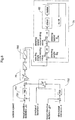
- Fig. 5 shows a variation of the control diagram of the electronic control unit 7 shown in Fig. 4 .
- the control diagram shown in Fig. 5 differs from Fig. 4 in that the target steering computation section 76 is added with a function of reducing the finally outputted target steering value according to the vehicle speed.
- Fig. 6 shows a variation of the control diagram of the electronic control unit 7 shown in Fig. 5 .
- the control diagram shown in Fig. 6 differs from Fig. 5 in that the target steering computation section 76 incorporates the steering upper limit setting section 760 and there is added a function of clamping the upper limit of the finally outputted target steering value.
- a maximum target steering value to be outputted is suppressed by a threshold value which varies according to the vehicle speed, such that the higher the vehicle speed, the smaller the maximum target steering value outputted.
Landscapes
- Engineering & Computer Science (AREA)
- Mechanical Engineering (AREA)
- Life Sciences & Earth Sciences (AREA)
- Chemical & Material Sciences (AREA)
- Combustion & Propulsion (AREA)
- Transportation (AREA)
- Physics & Mathematics (AREA)
- Soil Sciences (AREA)
- Environmental Sciences (AREA)
- Mathematical Physics (AREA)
- Aviation & Aerospace Engineering (AREA)
- Radar, Positioning & Navigation (AREA)
- Remote Sensing (AREA)
- General Physics & Mathematics (AREA)
- Automation & Control Theory (AREA)
- Guiding Agricultural Machines (AREA)
- Steering Control In Accordance With Driving Conditions (AREA)
- Control Of Position, Course, Altitude, Or Attitude Of Moving Bodies (AREA)
Abstract
Description
- The present invention relates to an auto traveling work vehicle configured to effect autosteered traveling along a set target traveling path.
- As an example of a work vehicle having an autosteering function to be autosteered along a set target traveling path,
Patent Literature 1 discloses a rice planter configured to produce a target path parallel with a teaching path produced by a teaching path producing means based on position information determined by a GPS (Global Positioning System) unit and to be caused to travel autonomously on the target path. - With this rice planter, an actual traveling path in the course of an auto traveling is determined by the GPS unit and a deviation amount between the target path and the actual traveling target path is computed for comparison with a preset threshold value. In this, an angle formed between the target path direction and the advancing direction is used as such deviation amount. And, if this deviation amount exceeds the threshold value, then, the direction of this deviation relative to a reference line is determined. If the deviation direction is deviation to the left side, a steering device will be corrected to the right direction in correspondence with the amount of this deviation. If the deviation direction is deviation to the right side, the steering device will be corrected to the left direction in correspondence with the amount of this deviation.
- However, with a work vehicle implementing such principle of auto traveling function, only an angle formed between the target path direction and the advancing direction is used as traveling deviation for steering control, appropriate traveling becomes difficult in case only the amount of deviation is large, although the target path; and in case the vehicle body are located in vicinity or the amount of deviation is small, although the target path and the vehicle body are located far apart from each other.
- According to a traveling control technique for a vehicle system disclosed in Patent Literature 2, for a target traveling path (a target track) including a variety of curvatures in a mixed state, a lateral deviation amount from a target traveling path, a deviation amount of direction therefrom and a curvature of the target traveling path are determined and a steering angle corresponding to the two deviation amounts and the curvature will be calculated and outputted.
- Specifically, a reference point is provided such that a vehicle position may be located in a normal line direction of the target traveling path. For this coordinate system, the coordinate system is converted from an absolute coordinate system of the vehicle position into a relative coordinate system relative to the reference point. Also, deviation amounts of the relative lateral displacement and the direction angle from the target traveling path are calculated; and a steering angle is obtained under the proportional control technique, based on a feedback-like operational amount corresponding to the deviation amounts and a feedforward-like operational amount corresponding to the curvature of the target lane and the lateral displacement amount.
- However, although this traveling control technique may be effective for e.g. an automobile which travels on a paved road, in the case of an agricultural work machine such as a rice planter, a tractor, a combine or a lawn mower, etc. or a civil engineering work machine such as a dozer, since the traveling speed of such machine or vehicle is low, for a same steering angle, it takes a long time for traveling deviation to be resolved as compared with a vehicle which travels at a high speed. Moreover, a momentary positional displacement from a target position may occur due to slippage or riding on an earth lump. Therefore, the traveling control technique disclosed in Patent Literature 2 cannot be applied as it is to an autosteered traveling of a work vehicle.
-
- Patent Literature 1: Japanese Unexamined Patent Application Publication No.
2008-131880 JP 2008-131880 A - Patent Literature 2: Japanese Unexamined Patent Application Publication No.
2002-215239 JP 2002-215239 A - In view of the above-described state of the art, an object of the present invention is to provide an auto traveling work vehicle which may effect the autosteered traveling along a set target traveling path with a high accuracy even during work traveling.
- An auto traveling work vehicle configured to effect autosteered traveling along a set target traveling path, comprising:
- a self vehicle position calculation section for calculating a self vehicle position;
- a self vehicle direction calculation section for calculating a traveling direction of the self vehicle;
- a positional deviation computation section for computing a positional deviation of the self vehicle position relative to the target traveling path;
- a directional deviation computation section for computing a directional deviation between a directional line of the target traveling path and the traveling direction;
- a first control computation section for outputting a first steering value computed for deviation resolution based on the positional deviation;
- a second control computation section for outputting a second steering value computed for the deviation resolution, based on the positional deviation and the directional deviation which is adjusted with using a weight coefficient which provides a progressively decreasing tendency with increase in the positional deviation;
- a target steering computation section for outputting a target steering value for traveling along the target traveling path based on the first steering value and the second steering value;
- a steering driving control section configured to input the target steering value and to output a steering driving signal; and
- a steering driving section for effecting steering of a steerable wheel based on the steering driving signal.
- With the above-described arrangement, a target steering value for traveling along the target traveling path is outputted from a positional deviation relative to the target traveling path and a direction deviation relative to the target traveling path. However, the arrangement does not simply obtain the first steering angle computed for deviation resolution from the positional deviation relative to the target traveling path and the second steering value computed for deviation resolution from the directional deviation relative to the target traveling path, but takes the positional deviation relative to the target traveling path additionally into consideration in the computation of the second steering value. More particularly, the arrangement introduces a weighting function for deriving a weight coefficient using the positional deviation as a variable, and configures this weighting function such that the weight coefficient tends to decrease progressively with increase in the positional deviation. Namely, suppose the positional deviation is represented by "d" and the weighting function is represented by "G", then the weight coefficient: w is obtained as: G (d). And, the function: G is a function which exhibits monotonous or stepwise decrease. Normally, w becomes a numerical value which is greater than 0 and equal to or less than 1. Such weight coefficient: w is used in a multiplication.
- With this, the second steering value for deviation resolution will be outputted based on the positional deviation and the directional deviation, under the condition that if the positional deviation is large, the weight for this positional deviation will be decreased. Then, based on the first steering value and the second steering value obtained as above, a final target steering value for traveling along the target traveling path will be outputted. With the above arrangement, in case the positional deviation is large, the target steering value which places priority on resolution of this positional deviation will be outputted, with disregarding (or "ignoring") the directional deviation to a certain extent. Therefore, If a large positional deviation (positional displacement) occurs due to slippage or riding over an earth lump, etc., this positional deviation can be resolved in a speedy manner. This is advantageous for a work vehicle such as a rice planter, a combine, a tractor, a lawn mower, etc. which needs to avoid significant deviation from a linear traveling path as much as possible, even at the cost of giving up traveling simply straight.
- Incidentally, in this disclosure, with assumption of a target traveling path being linear, a positional deviation is defined as a length of a perpendicular line drawn from a vehicle body to the target traveling path; and a directional deviation is defined as a value which can be represented by an angle formed between a traveling directional line of the vehicle body and the target traveling path.
- In the case of a control system configured to output a target steering value for appropriate deviation resolution in a low-speed or middle-speed traveling, if the steering angle remains the same, the higher the vehicle speed, the greater the positional or direction change of the vehicle body occurring in a fixed time period. As a result, there occurs a problem of the vehicle body tending to meander during high-speed traveling. For solving this problem, according to one preferred embodiment of the present invention: the auto traveling work vehicle further comprises a vehicle speed calculation section for calculating a vehicle speed; wherein, when the target steering computation section outputs the target steering value based on the first steering value and the second steering value, the target steering computation section is configured to decrease the target steering value if the vehicle speed is high, with using an adjustment coefficient providing a progressively decreasing tendency with increase in the vehicle speed. Specifically, the above arrangement introduces an adjustment function for deriving an adjustment coefficient (e.g. a numeric value greater than 0 and equal to or smaller than 1) using the vehicle speed as a variable; and configures this adjustment function such that the adjustment coefficient tends to decrease progressively with increase in the vehicle speed. Namely, suppose the vehicle speed is represented by "s" and the adjustment function is represented by "K", then, the adjustment coefficient: k is obtained as: K(k). And, the function: K is a function which exhibits monotonous or stepwise decrease. Such adjustment coefficient: k is used in a multiplication. With the above arrangement, the target steering value will be decreased if the vehicle speed becomes high. Whereby, appropriate deviation resolution from low speed traveling to high speed traveling will be realized, so that the autosteered traveling will become stable.
- As another measure to cope with the problem that the higher the vehicle speed, the greater the influence the steering angle for deviation resolution to the vehicle body, according to one preferred embodiment of the present invention: the target steering computation section has an upper limiter function for the target steering value, with an upper limit value being set according to the vehicle speed. Preferably, the upper limit value is variable according to a type of work. With this, appropriate deviation resolution from low speed traveling to high speed traveling will be realized, so that the autosteered traveling will become stable.
- As described above, according to one aspect of the present invention, in case positional deviation is large, a target steering value will be outputted with placing priority on resolution of the positional deviation, and with disregarding directional deviation to a certain extent. In this, if the degree of disregarding positional deviation is changed according to a situation of the soil on which work traveling is effected or a type of utility work, this will provide higher possibility of obtaining autosteered traveling more suited to the work. For this reason, according to one preferred embodiment of the present invention: degree of weight decrease by the second control computation section, using the weight coefficient for the directional deviation dependent on the amount of the positional deviation, is variable.
- For the sake of simplification of the target steering computation section for outputting a target steering value for traveling along the target traveling path based on the first steering value and the second steering value, according to one preferred embodiment of the present invention: the target steering computation section is configured to output the target steering value by adding up the first steering value and the second steering value. With this, by executing control for causing the vehicle body to progressively approach the target traveling path while executing control for causing a traveling direction of the vehicle body to be aligned with a line parallel with the target traveling path, it is possible to carry out a work traveling along a linear target traveling path which is required especially for a field work or the like.
-
- Fig. 1
- is a schematic for describing a basic principle of autosteered traveling control according to the present invention,
- Fig. 2
- is a side view showing a tractor as one embodiment of an auto traveling work vehicle relating to the present invention,
- Fig. 3
- is a functional block diagram showing a control system mounted in the tractor,
- Fig. 4
- is a control system diagram showing an autosteering control system,
- Fig. 5
- is a control system diagram showing a further autosteering control system, and
- Fig. 6
- is a control system diagram showing a still further autosteering control system.
- Before describing a specific embodiment of an auto traveling work vehicle relating to the present invention, a basic principle of autosteered traveling control according to the present invention will be described with reference to
Fig. 1 . Here, as such auto travelling work vehicle, there is assumed an agricultural work machine or vehicle such as a rice planter, a tractor, a combine, etc. which effects straight work traveling in a field by performing U-turns in repetition. The work vehicle is configured to effect autosteered traveling along a preset target traveling path. For effecting such autosteering, it is necessary to know a current position of the work vehicle (to be referred to as "self vehicle position" hereinafter) and a current traveling direction thereof (to be referred to as "self vehicle direction" hereinafter). To this end, this work vehicle is equipped with a satellite navigation device using a satellite called GPS (Global Positioning System) or GNSS (Global Navigation Satellite System), and an inertial navigation device using an accelerometer or a gyro. As shown inFig. 1 , here, the self vehicle position is represented by measurement values (latitude, longitude) about the work vehicle, and the self vehicle direction is represented by a traveling direction which is calculated from a change in position of the self vehicle occurring per unit time period. - As shown in
Fig. 1 , a distance: d is treated as a "positional deviation" which is defined between a straight line drawn from a work vehicle center in parallel with a straight target traveling path (directional line) and the target traveling path. And, an angle: θ is treated as a "directional deviation" which is formed between a vehicle body front/rear direction line extending through the vehicle body center (traveling direction) and the target traveling path. The self vehicle position used as a target in the autosteering travel control is a point located on the target traveling path, and the self vehicle direction used as the target is the direction of the target traveling path. Therefore, the positional deviation of the self position relative to the target traveling path will be "d", and the directional deviation of the traveling direction relative to the directional line of the target traveling path will be "θ". - Based on the positional deviation, a first steering value for resolving deviation is computed. For this computation, PID (Proportional-Integral-Differential) control computation can be advantageously employed. Based on the directional deviation, a second steering value for resolving deviation is computed. In this computation, the positional deviation will also be taken into consideration. If the positional deviation is large, the weight of the directional deviation for the second steering value will be decreased. For instance, there is produced a function: W(d) for deriving a weight coefficient: w (0<w<1) which provides a progressively decreasing value in response to increase in the position deviation for a value obtained by a function: F(θ) for deriving the second steering value. And, the second steering value is obtained by: W(d) x F(θ). Namely, in the case of large positional deviation, with decrease of the weight of the directional deviation, the second steering value for deviation resolution will be outputted based on the positional deviation and the directional deviation. Incidentally, it is preferred that the PID control computation be employed also in deriving the second steering value based on the directional deviation.
- Then, by using the first steering value and the second steering value thus obtained as inputs, a target steering value for the work vehicle to travel along the target traveling path is obtained and outputted. Most simply, such target steering value can be obtained by an arithmetic addition operation taking signs of the first steering value and the second steering value into consideration. Further, there is provided a steering control system configured to input this target steering value and then to output a steering driving signal to a steering driving section for driving a steering angle of a steerable wheel (including a crawler also) of the work vehicle. Such steering driving section can be constituted of an electric motor and/or a hydraulic device. Preferably, the steering control system is constituted of a PI (Proportional-Integral) feedback control technique, but can employ any other control technique as well. Here, as feedbacks, a steering speed and a steering angle are employed.
- Incidentally, as shown by a dotted line in
Fig. 1 , when the target steering value is to be obtained from the first steering value and the second steering value, a traveling speed of the work vehicle, namely, a vehicle speed, may be preferably taken into consideration as well. Namely, for a same steering angle, the higher the vehicle speed, the larger the posture change amount of the vehicle body occurring per unit time period. If this posture change amount per unit time period is too large, this will cause inconvenience of "roughing up" the field. For this reason, the target steering value, obtained from the first steering value and the second steering value, should be preferably decreased progressively with increase in the vehicle speed. For instance, at time of low speed traveling, the computed target steering value can be used as it is; whereas, at time of high speed traveling higher than a set speed, the target steering value can be decreased by a predetermined decrease ratio. - Next, one specific embodiment of the auto traveling work vehicle relating to the present invention will be described.
- As shown in
Fig. 2 , in the instant embodiment, the work vehicle is configured as a tractor mounting a utility implement for carrying out an agricultural work such as a cultivating work on a field delimited by a ridge. In this tractor, amaneuvering section 30 is formed at the center portion of avehicle body 3 supported byfront wheels 2a andrear wheels 2b. At a rear portion of thevehicle body 3, a ground work implement 5 is mounted via ahydraulic lift mechanism 4. Thefront wheels 2a function as "steerable wheels". By changing a steering angle thereof, a traveling direction of the tractor is changed. The steering angle of thefront wheels 2a is changed by an action of asteering mechanism 6. Thesteering mechanism 6 includes asteering driving section 60 for autosteering (to be described later, seeFig. 3 ). Controlling of an electric motor constituting thesteering driving section 60 is effected via a steering driving signal from an electronic control unit 7 (to be described later, seeFig. 3 andFig. 4 ). Incidentally, the steering angle of thefront wheels 2a can be changed also by an operation on a steering wheel as done conventionally. This steering wheel is disposed at themaneuvering section 30 of the tractor together with various control levers and a seat at which a driver is to be seated. At themaneuvering section 30, there is also disposed apositioning unit 8 for determining a self vehicle positon which is required at time of autosteering. Thispositioning unit 8 includes a satellite navigation module constituted as a GNSS module, as well as an inertial navigation module configured as a gyro module incorporating a gyro acceleration sensor or a compass sensor. The satellite navigation module includes a satellite antenna for receiving a GPS signal or a GNSS signal. But, illustration thereof is omitted inFig. 2 . -
Fig. 3 shows a control system mounted on this work vehicle. This control system employs the basic principle of autosteering control described above with reference toFig. 1 . The control system shown inFig. 3 includes theelectronic control unit 7, thepositioning unit 8, a switch/sensor group 9, and thesteering driving section 60. - The
positioning unit 8 includes thesatellite navigation module 81 for detecting compass directions such as latitude and longitude with using the GNSS, and its configuration is similar to that of a positioning unit for use in a car navigation system. Thepositioning unit 8 further includes theinertial navigation module 82 including e.g. a gyro acceleration sensor, for detecting an instantaneous movement of the work vehicle (directional vector or the like) and its direction, in supplementation to thesatellite navigation module 81. Thesteering driving section 60 adjusts the steering angle of thefront wheels 2a acting as steerable wheels, based on a steering driving signal outputted from theelectronic control unit 7. The switch/sensor group 9 comprises a generic reference to sensors and/or switches for detecting a traveling state and setting situation of the work vehicle. Detection signals therefrom will be inputted to theelectronic control unit 7 to be used as input parameters for various kinds of control. The switch/sensor group 9 includes also a sensor for outputting a detection signal for calculation of a vehicle speed, and a sensor for outputting a detection signal for calculation of a driving state of the steering driving section 60 (e.g. an operational speed and a steering angle). - The
electronic control unit 7 includes, as functional sections relating especially to the present invention, a referencepath acquisition section 71, a referencepath setting section 72, a self vehicleposition calculation section 731, a self vehicledirection calculation section 732, a positionaldeviation computation section 741, a directionaldeviation computation section 742, a firstcontrol computation section 751, a secondcontrol computation section 752, a targetsteering computation section 76, a vehiclespeed calculation section 78 and a steering drivingcontrol section 79. - The reference
path acquisition section 71 acquires the target traveling path for autosteered work traveling, based on field information such as a map position of the field as the subject of work, position data of the ridge delimiting the borderline of this field, and work information relating to the work to be carried out in the field, such as device setting data (e.g. a working width). For acquisition of the target traveling path, it is possible to employ downloading from a management server installed at a remote site, reading from target traveling paths stored in the work vehicle per se according to fields and types of work, etc. Alternatively, the target traveling path may be obtained by a computation on each occasion, with using an algorithm for target traveling path calculation. Further alternatively, the target traveling path may be calculated via teaching traveling also. - Upon decision of the target traveling path, the reference
path setting section 72 will incorporate this target traveling path into its map for work traveling and execute processing thereof so that the target traveling path may be utilized as a control target for autosteering traveling. - The self vehicle
position calculation section 731 calculates a self vehicle position in the work traveling map based on positioning data transmitted from thepositioning unit 8. The self vehicledirection calculation section 732 calculates a traveling direction of the self vehicle in the work traveling map based on the positioning data transmitted from thepositioning unit 8. The positionaldeviation computation section 741 computes a positional deviation (denoted by a sign: d inFig. 1 ) between the target traveling path and the self vehicle position. The directionaldeviation computation section 742 computes a directional deviation (denoted by a sign: θ inFig. 1 ) between a directional line of the target traveling path and the traveling direction. - The first
control computation section 751 outputs a first steering value computed for deviation resolution based on the positional deviation. The secondcontrol computation section 752 outputs a second steering value computed for deviation resolution based on the positional deviation and the directional deviation, with decrease of the weight of the directional deviation using the above-described weight coefficient in case the positional deviation is large. Alternatively, the secondcontrol computation section 752 may be configured to output a temporary second steering value for deviation resolution based on the directional deviation and to decrease this temporary second steering value progressively with increase in the positional deviation, and then to output the result as the final second steering value. Incidentally, the degree of decrease of the directional deviation depending on the magnitude of the positional deviation is adjustable or variable via an input device. - The target
steering computation section 76 outputs a target steering value for the work vehicle to travel along the target traveling path, based on the first steering value and the second steering value. In a simplest configuration, a result of an arithmetic addition computation of the first steering value and the second steering value becomes the target steering value. At the steering drivingcontrol section 79, the target steering value outputted from the targetsteering computation section 76 will be used as an input parameter for control computation for outputting the steering driving signal for driving thesteering driving section 60. - In the instant embodiment, when the target steering value is computed, the target
steering computation section 76 functions to take into consideration the vehicle speed of the work vehicle obtained from the vehiclespeed calculation section 78, such that when the vehicle speed is high, the targetsteering computation section 76 will decrease the target steering value which is outputted based on the first steering value and the second steering value. More particularly, when the target steering value is to be outputted based on the first steering value and the second steering value, the targetsteering computation section 76 will decrease the target steering value in the case of high vehicle speed, with using an adjustment coefficient: k which provides a progressively decreasing tendency with increase in the vehicle speed. - Moreover, the target
steering computation section 76 incorporates a steering upperlimit setting section 760. This steering upperlimit setting section 760 has a function of "clamping" an upper limit for a target steering value obtained with using the first steering value and the second steering value and also the vehicle speed when appropriate, namely, an upper limiter function. Preferably, this upper limit value too should be made variable according to the vehicle speed. Namely, a maximum target steering value may be progressively decreased in correspondence with increase in the vehicle speed, and then the steering stability will be improved at time of high speed traveling. - With reference to a control diagram shown in
Fig. 4 next, the specific controlling configuration of theelectronic control unit 7 constructed as above will be described. Under the PI control, the firstcontrol computation section 751 computes and outputs the first steering value for reducing the positional deviation: d, with using a target positional deviation: Δd and the positional deviation: d as input parameters. In this, the PID control may be employed instead of the PI control. The secondcontrol computation section 752 computes and outputs, by using the PI control, the second steering value for reducing the directional deviation: θ with using a target directional deviation: Δθ and the directional deviation: θ as input parameters. In this, the PID control may be employed instead of the PI control. If the positional deviation is large, however, the secondcontrol computation section 752 may decrease a temporary second steering value obtained based on the directional deviation, linearly or non-linearly according to the positional deviation amount, and then output the result thereof. The targetsteering computation section 76 controls and outputs, as a target steering value, an addition value of the first steering value outputted from the firstcontrol computation section 751 and the second steering value outputted from the secondcontrol computation section 752. - The steering driving
control section 79 is configured as a feedback type steering control module. In this, by inputting a steering angle commanding value: Sθ* obtained by comparison computation between the inputted target steering value and an actual steering angle: Sθ, a front stage output value will be obtained with using the PI control. This front stage output value will be subjected to comparison computation with an actual steering speed: Sω outputted from a speed computing unit: du/dt using differentiation. Then, under the PI control with using the result of the computation (steering speed commanding value: Sω*) as an input, a steering driving signal will be outputted. The steering driving signal will drive, via a driver, the motor in thesteering driving section 60, to thereby steer thefront wheels 2a. - Incidentally, the PI control used in the steering driving
control section 79 may be replaced by the PID control. -
Fig. 5 shows a variation of the control diagram of theelectronic control unit 7 shown inFig. 4 . The control diagram shown inFig. 5 differs fromFig. 4 in that the targetsteering computation section 76 is added with a function of reducing the finally outputted target steering value according to the vehicle speed. - Namely, in this variation, there is added a computation function of progressively reducing the addition value of the first steering value outputted from the first
control computation section 751 and the second steering value outputted from the secondcontrol computation section 752, with increase in the vehicle speed. -
Fig. 6 shows a variation of the control diagram of theelectronic control unit 7 shown inFig. 5 . The control diagram shown inFig. 6 differs fromFig. 5 in that the targetsteering computation section 76 incorporates the steering upperlimit setting section 760 and there is added a function of clamping the upper limit of the finally outputted target steering value. - Namely, in this variation, prior to outputting of an obtained target steering value, a maximum target steering value to be outputted is suppressed by a threshold value which varies according to the vehicle speed, such that the higher the vehicle speed, the smaller the maximum target steering value outputted.
-
- (1) In the foregoing embodiment, the steering driving
control section 79 was configured as a steering control module using an actual steering angle and steering speed as feedback amounts. However, in the present invention, the controlling configuration of the steering drivingcontrol section 79 is not particularly limited, but any other known controlling configuration may be employed also. - (2) In the foregoing embodiment, the target traveling path was assumed to be a linear or straight path. However, the present invention is applicable also to an arrangement of the target traveling path being a curved path.
- (3) In the foregoing embodiment, the
positioning unit 8 was constituted of thesatellite navigation module 81 and theinertial navigation module 82. Instead, theunit 8 may include thesatellite navigation module 81 alone. - (4) In the foregoing embodiment, a tractor was disclosed as an example of the auto traveling work vehicle. However, the work vehicle is not limited thereto. The auto traveling work vehicle may be any other agricultural work vehicle, such as a rice planter, a combine, etc. that mounts various implements and that is capable of autosteered traveling. Further, the present invention is applicable not only to agricultural work vehicles, but to other work vehicles.
-
- 60
- steering driving section
- 76
- target steering computation section
- 78
- vehicle speed calculation section
- 79
- steering driving control section
- 731
- self vehicle position calculation section
- 732
- self vehicle direction calculation section
- 741
- positional deviation computation section
- 742
- directional deviation computation section
- 751
- first control computation section
- 752
- second control computation section
Claims (5)
- An auto traveling work vehicle configured to effect autosteered traveling along a set target traveling path, comprising:- a self vehicle position calculation section for calculating a self vehicle position;- a self vehicle direction calculation section for calculating a traveling direction of the self vehicle;- a positional deviation computation section for computing a positional deviation of the self vehicle position relative to the target traveling path;- a directional deviation computation section for computing a directional deviation between a directional line of the target traveling path and the traveling direction;- a first control computation section for outputting a first steering value computed for deviation resolution based on the positional deviation;- a second control computation section for outputting a second steering value computed for the deviation resolution, based on the positional deviation and the directional deviation which is adjusted with using a weight coefficient which provides a progressively decreasing tendency with increase in the positional deviation;- a target steering computation section for outputting a target steering value for traveling along the target traveling path based on the first steering value and the second steering value;- a steering driving control section configured to input the target steering value and to output a steering driving signal; and- a steering driving section for effecting steering of a steerable wheel based on the steering driving signal.
- The auto traveling work vehicle of claim 1, further comprising:- a vehicle speed calculation section for calculating a vehicle speed;wherein, when the target steering computation section outputs the target steering value based on the first steering value and the second steering value, the target steering computation section is configured to decrease the target steering value if the vehicle speed is high, with using an adjustment coefficient providing a progressively decreasing tendency with increase in the vehicle speed.
- The auto traveling work vehicle of claim 1 or 2, further comprising:- a vehicle speed calculation section for calculating a vehicle speed;wherein the target steering computation section has an upper limiter function for the target steering value, with an upper limit value being set according to the vehicle speed.
- The auto traveling work vehicle of any one of claims 1-3, wherein degree of weight decrease by the second control computation section, using the weight coefficient for the directional deviation dependent on the amount of the positional deviation, is variable.
- The auto traveling work vehicle of any one of claims 1-4, wherein the target steering computation section is configured to output the target steering value by adding up the first steering value and the second steering value.
Applications Claiming Priority (1)
| Application Number | Priority Date | Filing Date | Title |
|---|---|---|---|
| PCT/JP2016/065918 WO2017208306A1 (en) | 2016-05-30 | 2016-05-30 | Autonomous work vehicle |
Publications (3)
| Publication Number | Publication Date |
|---|---|
| EP3467606A1 true EP3467606A1 (en) | 2019-04-10 |
| EP3467606A4 EP3467606A4 (en) | 2020-01-29 |
| EP3467606B1 EP3467606B1 (en) | 2022-07-20 |
Family
ID=60478207
Family Applications (1)
| Application Number | Title | Priority Date | Filing Date |
|---|---|---|---|
| EP16903934.4A Active EP3467606B1 (en) | 2016-05-30 | 2016-05-30 | Autonomous work vehicle |
Country Status (4)
| Country | Link |
|---|---|
| US (1) | US10602654B2 (en) |
| EP (1) | EP3467606B1 (en) |
| CN (1) | CN109154817B (en) |
| WO (1) | WO2017208306A1 (en) |
Families Citing this family (22)
| Publication number | Priority date | Publication date | Assignee | Title |
|---|---|---|---|---|
| CN111372440B (en) | 2017-12-18 | 2022-10-04 | 株式会社久保田 | Automatic steering system and automatic steering method |
| KR102745013B1 (en) * | 2017-12-18 | 2024-12-20 | 가부시끼 가이샤 구보다 | Work vehicles and tractors |
| CN111447826B (en) * | 2018-01-23 | 2023-01-31 | 株式会社久保田 | Working vehicle |
| US11154008B2 (en) * | 2018-08-20 | 2021-10-26 | Cnh Industrial America Llc | System and method for steering an agricultural harvester |
| US10696324B2 (en) * | 2018-10-15 | 2020-06-30 | Caterpillar Paving Products Inc. | Controlling machine operation including machine turning radius |
| JP7269255B2 (en) * | 2018-10-30 | 2023-05-08 | 東京計器株式会社 | Error correction device |
| CN109900273B (en) * | 2019-02-28 | 2021-02-09 | 北京航天自动控制研究所 | Guide method and guide system for outdoor mobile robot |
| JP7346980B2 (en) * | 2019-07-30 | 2023-09-20 | マツダ株式会社 | vehicle control system |
| CN112384872B (en) * | 2019-08-30 | 2024-02-27 | 深圳市大疆创新科技有限公司 | Movable platform and driving control method and system and control equipment thereof |
| JP7342541B2 (en) * | 2019-09-06 | 2023-09-12 | オムロン株式会社 | House management system, house management device, house management method and program |
| CN112650206A (en) * | 2019-10-10 | 2021-04-13 | 苏州宝时得电动工具有限公司 | Intelligent mower walking control method and intelligent mower |
| US10935986B1 (en) * | 2019-11-28 | 2021-03-02 | Institute Of Automation, Chinese Academy Of Sciences | Gliding depth control method, system and device for biomimetic gliding robotic dolphin |
| JP7497669B2 (en) * | 2020-10-28 | 2024-06-11 | 井関農機株式会社 | Automatic Control Combine Harvester |
| JP7648650B2 (en) | 2020-11-18 | 2025-03-18 | 株式会社クボタ | MOBILE BODY, CONTROL UNIT, AND METHOD FOR CONTROLLING OPERATION OF MOBILE BODY |
| EP4250046A4 (en) | 2020-11-18 | 2024-07-24 | Kubota Corporation | MOVING BODY, CONTROL UNIT, DATA GENERATION UNIT, METHOD FOR CONTROLLING MOVING BODY MOVEMENT, AND DATA GENERATION METHOD |
| JP7684327B2 (en) | 2020-11-18 | 2025-05-27 | 株式会社クボタ | MOBILE BODY, DATA GENERATION UNIT, AND METHOD FOR GENERATING DATA - Patent application |
| CN112533143A (en) * | 2020-12-02 | 2021-03-19 | 董树波 | Carpet direction positioning method and system based on smart phone connection |
| JP7502174B2 (en) | 2020-12-22 | 2024-06-18 | 株式会社クボタ | Agricultural machinery and system and method for controlling an agricultural machinery |
| US12108696B2 (en) | 2021-12-23 | 2024-10-08 | Cnh Industrial America Llc | Agricultural system and method for determining an as-driven path of an agricultural work vehicle |
| DE102022105922A1 (en) * | 2022-03-14 | 2023-09-14 | Krone Agriculture Se | METHOD FOR ROUTE OPTIMIZATION |
| CN116022235B (en) * | 2023-03-29 | 2023-06-16 | 北京理工大学深圳汽车研究院(电动车辆国家工程实验室深圳研究院) | Vehicle steering control method and device and vehicle |
| CN121180302B (en) * | 2025-11-24 | 2026-02-03 | 厦门金龙联合汽车工业有限公司 | A Distributed Cooperative Control Method for Hydraulic Braking and Steering of Heavy-Duty IGVs in Ports |
Family Cites Families (30)
| Publication number | Priority date | Publication date | Assignee | Title |
|---|---|---|---|---|
| JPS63153605A (en) | 1986-12-17 | 1988-06-27 | Kubota Ltd | Steering controller for automatic traveling working vehicle |
| JP3286334B2 (en) | 1992-01-17 | 2002-05-27 | 本田技研工業株式会社 | Mobile unit control device |
| JPH07223600A (en) * | 1994-02-14 | 1995-08-22 | Mitsubishi Heavy Ind Ltd | Attitude control device for space shuttle |
| JP3281188B2 (en) | 1994-08-09 | 2002-05-13 | ヤマハ発動機株式会社 | Unmanned car |
| DE59805985D1 (en) * | 1997-06-28 | 2002-11-21 | Kostal Leopold Gmbh & Co Kg | METHOD FOR DETERMINING THE ABSOLUTE ANGLE POSITION OF THE STEERING WHEEL OF A MOTOR VEHICLE AND OPTOELECTRONIC STEERING ANGLE SENSOR |
| JP2001350521A (en) * | 2000-06-07 | 2001-12-21 | Nissan Motor Co Ltd | Automatic vehicle steering system |
| JP3483855B2 (en) | 2001-01-16 | 2004-01-06 | 川崎重工業株式会社 | Vehicle-based traveling control method and apparatus |
| JP2002333922A (en) * | 2001-05-10 | 2002-11-22 | Isuzu Motors Ltd | Automatic steering device |
| KR100580628B1 (en) * | 2003-11-08 | 2006-05-16 | 삼성전자주식회사 | Method and system for estimating moving direction of moving object |
| JP2006268499A (en) * | 2005-03-24 | 2006-10-05 | Funai Electric Co Ltd | Traveling machines and self-propelled vacuum cleaners. |
| JP4195897B2 (en) * | 2006-05-26 | 2008-12-17 | オリエンタルモーター株式会社 | Stepping motor control device |
| JP2008131880A (en) | 2006-11-28 | 2008-06-12 | Yanmar Co Ltd | Agricultural working vehicle |
| JP4920393B2 (en) | 2006-12-08 | 2012-04-18 | 本田技研工業株式会社 | Vehicle steering control device |
| JP5045108B2 (en) | 2007-01-11 | 2012-10-10 | トヨタ自動車株式会社 | Driving support device |
| CN101118421A (en) * | 2007-09-13 | 2008-02-06 | 北京航空航天大学 | Parameter Tuning Method of Nonlinear PID Control Based on Adaptive Ant Colony Intelligence |
| JP5389360B2 (en) | 2008-01-09 | 2014-01-15 | 富士重工業株式会社 | Lane tracking control device and lane tracking control method |
| CN101221447A (en) * | 2008-01-18 | 2008-07-16 | 中国农业大学 | A kind of mechanical automatic steering control method |
| JP5359085B2 (en) | 2008-03-04 | 2013-12-04 | 日産自動車株式会社 | Lane maintenance support device and lane maintenance support method |
| JP2010238217A (en) * | 2009-03-09 | 2010-10-21 | Yaskawa Electric Corp | Mobile robot self-position identification method and mobile robot |
| WO2010143291A1 (en) * | 2009-06-11 | 2010-12-16 | トヨタ自動車株式会社 | Method for judging vehicle traveling position and vehicle traveling position judgment device |
| JP2010152923A (en) * | 2010-03-04 | 2010-07-08 | ▲吉▼川 英之 | Remote control device |
| CN102147262A (en) * | 2011-01-11 | 2011-08-10 | 北京理工大学 | Method for correcting navigation deviation and navigation display adopting same |
| US9020757B2 (en) * | 2012-05-11 | 2015-04-28 | Trimble Navigation Limited | Path planning autopilot |
| JP5977203B2 (en) * | 2012-12-21 | 2016-08-24 | 株式会社日本自動車部品総合研究所 | Vehicle control device |
| WO2015033968A1 (en) * | 2013-09-04 | 2015-03-12 | 株式会社クボタ | Agricultural assistance system |
| JP5939238B2 (en) * | 2013-11-29 | 2016-06-22 | トヨタ自動車株式会社 | Vehicle steering control device |
| CN103744428B (en) * | 2014-01-17 | 2016-03-09 | 哈尔滨工程大学 | A kind of unmanned surface vehicle paths planning method based on neighborhood intelligent water drop algorithm |
| CN104536453B (en) * | 2014-11-28 | 2017-08-04 | 深圳一电航空技术有限公司 | The control method and device of aircraft |
| CN104881025B (en) * | 2015-04-10 | 2018-11-27 | 北京科技大学 | A kind of reactive navigation control method of underground mine vehicle |
| CN105007012B (en) * | 2015-07-16 | 2017-12-15 | 湖北三江航天万峰科技发展有限公司 | A kind of vehicle-mounted rotating table control system and method |
-
2016
- 2016-05-30 WO PCT/JP2016/065918 patent/WO2017208306A1/en not_active Ceased
- 2016-05-30 US US16/099,892 patent/US10602654B2/en active Active
- 2016-05-30 EP EP16903934.4A patent/EP3467606B1/en active Active
- 2016-05-30 CN CN201680085801.XA patent/CN109154817B/en active Active
Also Published As
| Publication number | Publication date |
|---|---|
| WO2017208306A1 (en) | 2017-12-07 |
| EP3467606A4 (en) | 2020-01-29 |
| US10602654B2 (en) | 2020-03-31 |
| EP3467606B1 (en) | 2022-07-20 |
| CN109154817A (en) | 2019-01-04 |
| CN109154817B (en) | 2021-09-24 |
| US20190133023A1 (en) | 2019-05-09 |
Similar Documents
| Publication | Publication Date | Title |
|---|---|---|
| US10602654B2 (en) | Auto traveling work vehicle | |
| JP6420173B2 (en) | Automated traveling field work vehicle | |
| CN106476883B (en) | The travel controlling system of vehicle | |
| JP6528786B2 (en) | Driving support device for vehicle | |
| Daily et al. | The use of GPS for vehicle stability control systems | |
| US11937526B2 (en) | Control device for work vehicle configured to travel autonomously | |
| US6768283B2 (en) | Electric power steering control device | |
| JP6860387B2 (en) | Work platform | |
| JP6087969B2 (en) | Vehicle travel control device | |
| US20090292412A1 (en) | Vehicular Guidance System Having Compensation for Variations in Ground Elevation | |
| WO2014155893A1 (en) | Work vehicle automatic steering system | |
| WO2019054057A1 (en) | Autonomous travel system for work vehicle | |
| JP6850759B2 (en) | Autonomous steering device | |
| CN107943060A (en) | A kind of automatic pilot, method and computer-readable medium along tracking straight line guiding vehicle | |
| JP2019038535A (en) | Automated traveling field work vehicle | |
| JP2017030396A (en) | Vehicle travel control device | |
| Bian et al. | Kinematics and path following control of an articulated drum roller | |
| JP2020164160A (en) | Self-driving field work vehicle | |
| JP6811655B2 (en) | Work platform | |
| KR20190009018A (en) | Velocity Control Apparatus and the Mehod for Working Safety of Automatic Driving Agricultural Machine | |
| JP2003276628A (en) | Automatic steering device | |
| JP6871831B2 (en) | Autonomous driving system for work vehicles | |
| JP6976782B2 (en) | Autonomous driving system for work vehicles | |
| JP2005250696A (en) | Vehicle autonomous driving control system and method | |
| JP7012001B2 (en) | Vehicle posture estimation device |
Legal Events
| Date | Code | Title | Description |
|---|---|---|---|
| STAA | Information on the status of an ep patent application or granted ep patent |
Free format text: STATUS: THE INTERNATIONAL PUBLICATION HAS BEEN MADE |
|
| PUAI | Public reference made under article 153(3) epc to a published international application that has entered the european phase |
Free format text: ORIGINAL CODE: 0009012 |
|
| STAA | Information on the status of an ep patent application or granted ep patent |
Free format text: STATUS: REQUEST FOR EXAMINATION WAS MADE |
|
| 17P | Request for examination filed |
Effective date: 20181107 |
|
| AK | Designated contracting states |
Kind code of ref document: A1 Designated state(s): AL AT BE BG CH CY CZ DE DK EE ES FI FR GB GR HR HU IE IS IT LI LT LU LV MC MK MT NL NO PL PT RO RS SE SI SK SM TR |
|
| AX | Request for extension of the european patent |
Extension state: BA ME |
|
| DAV | Request for validation of the european patent (deleted) | ||
| DAX | Request for extension of the european patent (deleted) | ||
| A4 | Supplementary search report drawn up and despatched |
Effective date: 20200108 |
|
| RIC1 | Information provided on ipc code assigned before grant |
Ipc: B62D 1/28 20060101ALI20191220BHEP Ipc: E02F 9/20 20060101ALN20191220BHEP Ipc: G05D 1/02 20060101AFI20191220BHEP Ipc: A01D 41/127 20060101ALN20191220BHEP |
|
| GRAP | Despatch of communication of intention to grant a patent |
Free format text: ORIGINAL CODE: EPIDOSNIGR1 |
|
| STAA | Information on the status of an ep patent application or granted ep patent |
Free format text: STATUS: GRANT OF PATENT IS INTENDED |
|
| INTG | Intention to grant announced |
Effective date: 20220311 |
|
| GRAS | Grant fee paid |
Free format text: ORIGINAL CODE: EPIDOSNIGR3 |
|
| GRAA | (expected) grant |
Free format text: ORIGINAL CODE: 0009210 |
|
| STAA | Information on the status of an ep patent application or granted ep patent |
Free format text: STATUS: THE PATENT HAS BEEN GRANTED |
|
| AK | Designated contracting states |
Kind code of ref document: B1 Designated state(s): AL AT BE BG CH CY CZ DE DK EE ES FI FR GB GR HR HU IE IS IT LI LT LU LV MC MK MT NL NO PL PT RO RS SE SI SK SM TR |
|
| REG | Reference to a national code |
Ref country code: CH Ref legal event code: EP |
|
| REG | Reference to a national code |
Ref country code: DE Ref legal event code: R096 Ref document number: 602016073709 Country of ref document: DE |
|
| REG | Reference to a national code |
Ref country code: AT Ref legal event code: REF Ref document number: 1505932 Country of ref document: AT Kind code of ref document: T Effective date: 20220815 |
|
| REG | Reference to a national code |
Ref country code: IE Ref legal event code: FG4D |
|
| REG | Reference to a national code |
Ref country code: LT Ref legal event code: MG9D |
|
| REG | Reference to a national code |
Ref country code: NL Ref legal event code: MP Effective date: 20220720 |
|
| PG25 | Lapsed in a contracting state [announced via postgrant information from national office to epo] |
Ref country code: SE Free format text: LAPSE BECAUSE OF FAILURE TO SUBMIT A TRANSLATION OF THE DESCRIPTION OR TO PAY THE FEE WITHIN THE PRESCRIBED TIME-LIMIT Effective date: 20220720 Ref country code: RS Free format text: LAPSE BECAUSE OF FAILURE TO SUBMIT A TRANSLATION OF THE DESCRIPTION OR TO PAY THE FEE WITHIN THE PRESCRIBED TIME-LIMIT Effective date: 20220720 Ref country code: PT Free format text: LAPSE BECAUSE OF FAILURE TO SUBMIT A TRANSLATION OF THE DESCRIPTION OR TO PAY THE FEE WITHIN THE PRESCRIBED TIME-LIMIT Effective date: 20221121 Ref country code: NO Free format text: LAPSE BECAUSE OF FAILURE TO SUBMIT A TRANSLATION OF THE DESCRIPTION OR TO PAY THE FEE WITHIN THE PRESCRIBED TIME-LIMIT Effective date: 20221020 Ref country code: NL Free format text: LAPSE BECAUSE OF FAILURE TO SUBMIT A TRANSLATION OF THE DESCRIPTION OR TO PAY THE FEE WITHIN THE PRESCRIBED TIME-LIMIT Effective date: 20220720 Ref country code: LV Free format text: LAPSE BECAUSE OF FAILURE TO SUBMIT A TRANSLATION OF THE DESCRIPTION OR TO PAY THE FEE WITHIN THE PRESCRIBED TIME-LIMIT Effective date: 20220720 Ref country code: LT Free format text: LAPSE BECAUSE OF FAILURE TO SUBMIT A TRANSLATION OF THE DESCRIPTION OR TO PAY THE FEE WITHIN THE PRESCRIBED TIME-LIMIT Effective date: 20220720 Ref country code: FI Free format text: LAPSE BECAUSE OF FAILURE TO SUBMIT A TRANSLATION OF THE DESCRIPTION OR TO PAY THE FEE WITHIN THE PRESCRIBED TIME-LIMIT Effective date: 20220720 Ref country code: ES Free format text: LAPSE BECAUSE OF FAILURE TO SUBMIT A TRANSLATION OF THE DESCRIPTION OR TO PAY THE FEE WITHIN THE PRESCRIBED TIME-LIMIT Effective date: 20220720 |
|
| REG | Reference to a national code |
Ref country code: AT Ref legal event code: MK05 Ref document number: 1505932 Country of ref document: AT Kind code of ref document: T Effective date: 20220720 |
|
| PG25 | Lapsed in a contracting state [announced via postgrant information from national office to epo] |
Ref country code: PL Free format text: LAPSE BECAUSE OF FAILURE TO SUBMIT A TRANSLATION OF THE DESCRIPTION OR TO PAY THE FEE WITHIN THE PRESCRIBED TIME-LIMIT Effective date: 20220720 Ref country code: IS Free format text: LAPSE BECAUSE OF FAILURE TO SUBMIT A TRANSLATION OF THE DESCRIPTION OR TO PAY THE FEE WITHIN THE PRESCRIBED TIME-LIMIT Effective date: 20221120 Ref country code: HR Free format text: LAPSE BECAUSE OF FAILURE TO SUBMIT A TRANSLATION OF THE DESCRIPTION OR TO PAY THE FEE WITHIN THE PRESCRIBED TIME-LIMIT Effective date: 20220720 Ref country code: GR Free format text: LAPSE BECAUSE OF FAILURE TO SUBMIT A TRANSLATION OF THE DESCRIPTION OR TO PAY THE FEE WITHIN THE PRESCRIBED TIME-LIMIT Effective date: 20221021 |
|
| REG | Reference to a national code |
Ref country code: DE Ref legal event code: R097 Ref document number: 602016073709 Country of ref document: DE |
|
| PG25 | Lapsed in a contracting state [announced via postgrant information from national office to epo] |
Ref country code: SM Free format text: LAPSE BECAUSE OF FAILURE TO SUBMIT A TRANSLATION OF THE DESCRIPTION OR TO PAY THE FEE WITHIN THE PRESCRIBED TIME-LIMIT Effective date: 20220720 Ref country code: RO Free format text: LAPSE BECAUSE OF FAILURE TO SUBMIT A TRANSLATION OF THE DESCRIPTION OR TO PAY THE FEE WITHIN THE PRESCRIBED TIME-LIMIT Effective date: 20220720 Ref country code: DK Free format text: LAPSE BECAUSE OF FAILURE TO SUBMIT A TRANSLATION OF THE DESCRIPTION OR TO PAY THE FEE WITHIN THE PRESCRIBED TIME-LIMIT Effective date: 20220720 Ref country code: CZ Free format text: LAPSE BECAUSE OF FAILURE TO SUBMIT A TRANSLATION OF THE DESCRIPTION OR TO PAY THE FEE WITHIN THE PRESCRIBED TIME-LIMIT Effective date: 20220720 Ref country code: AT Free format text: LAPSE BECAUSE OF FAILURE TO SUBMIT A TRANSLATION OF THE DESCRIPTION OR TO PAY THE FEE WITHIN THE PRESCRIBED TIME-LIMIT Effective date: 20220720 |
|
| PLBE | No opposition filed within time limit |
Free format text: ORIGINAL CODE: 0009261 |
|
| STAA | Information on the status of an ep patent application or granted ep patent |
Free format text: STATUS: NO OPPOSITION FILED WITHIN TIME LIMIT |
|
| PG25 | Lapsed in a contracting state [announced via postgrant information from national office to epo] |
Ref country code: SK Free format text: LAPSE BECAUSE OF FAILURE TO SUBMIT A TRANSLATION OF THE DESCRIPTION OR TO PAY THE FEE WITHIN THE PRESCRIBED TIME-LIMIT Effective date: 20220720 Ref country code: EE Free format text: LAPSE BECAUSE OF FAILURE TO SUBMIT A TRANSLATION OF THE DESCRIPTION OR TO PAY THE FEE WITHIN THE PRESCRIBED TIME-LIMIT Effective date: 20220720 |
|
| 26N | No opposition filed |
Effective date: 20230421 |
|
| PG25 | Lapsed in a contracting state [announced via postgrant information from national office to epo] |
Ref country code: AL Free format text: LAPSE BECAUSE OF FAILURE TO SUBMIT A TRANSLATION OF THE DESCRIPTION OR TO PAY THE FEE WITHIN THE PRESCRIBED TIME-LIMIT Effective date: 20220720 |
|
| PG25 | Lapsed in a contracting state [announced via postgrant information from national office to epo] |
Ref country code: SI Free format text: LAPSE BECAUSE OF FAILURE TO SUBMIT A TRANSLATION OF THE DESCRIPTION OR TO PAY THE FEE WITHIN THE PRESCRIBED TIME-LIMIT Effective date: 20220720 |
|
| REG | Reference to a national code |
Ref country code: DE Ref legal event code: R079 Ref document number: 602016073709 Country of ref document: DE Free format text: PREVIOUS MAIN CLASS: G05D0001020000 Ipc: G05D0001430000 |
|
| REG | Reference to a national code |
Ref country code: CH Ref legal event code: PL |
|
| PG25 | Lapsed in a contracting state [announced via postgrant information from national office to epo] |
Ref country code: MC Free format text: LAPSE BECAUSE OF FAILURE TO SUBMIT A TRANSLATION OF THE DESCRIPTION OR TO PAY THE FEE WITHIN THE PRESCRIBED TIME-LIMIT Effective date: 20220720 |
|
| GBPC | Gb: european patent ceased through non-payment of renewal fee |
Effective date: 20230530 |
|
| REG | Reference to a national code |
Ref country code: BE Ref legal event code: MM Effective date: 20230531 |
|
| PG25 | Lapsed in a contracting state [announced via postgrant information from national office to epo] |
Ref country code: MC Free format text: LAPSE BECAUSE OF FAILURE TO SUBMIT A TRANSLATION OF THE DESCRIPTION OR TO PAY THE FEE WITHIN THE PRESCRIBED TIME-LIMIT Effective date: 20220720 Ref country code: LU Free format text: LAPSE BECAUSE OF NON-PAYMENT OF DUE FEES Effective date: 20230530 Ref country code: LI Free format text: LAPSE BECAUSE OF NON-PAYMENT OF DUE FEES Effective date: 20230531 Ref country code: CH Free format text: LAPSE BECAUSE OF NON-PAYMENT OF DUE FEES Effective date: 20230531 |
|
| REG | Reference to a national code |
Ref country code: IE Ref legal event code: MM4A |
|
| PG25 | Lapsed in a contracting state [announced via postgrant information from national office to epo] |
Ref country code: IE Free format text: LAPSE BECAUSE OF NON-PAYMENT OF DUE FEES Effective date: 20230530 |
|
| PG25 | Lapsed in a contracting state [announced via postgrant information from national office to epo] |
Ref country code: IE Free format text: LAPSE BECAUSE OF NON-PAYMENT OF DUE FEES Effective date: 20230530 Ref country code: GB Free format text: LAPSE BECAUSE OF NON-PAYMENT OF DUE FEES Effective date: 20230530 |
|
| PG25 | Lapsed in a contracting state [announced via postgrant information from national office to epo] |
Ref country code: IT Free format text: LAPSE BECAUSE OF FAILURE TO SUBMIT A TRANSLATION OF THE DESCRIPTION OR TO PAY THE FEE WITHIN THE PRESCRIBED TIME-LIMIT Effective date: 20220720 Ref country code: BE Free format text: LAPSE BECAUSE OF NON-PAYMENT OF DUE FEES Effective date: 20230531 |
|
| PG25 | Lapsed in a contracting state [announced via postgrant information from national office to epo] |
Ref country code: BG Free format text: LAPSE BECAUSE OF FAILURE TO SUBMIT A TRANSLATION OF THE DESCRIPTION OR TO PAY THE FEE WITHIN THE PRESCRIBED TIME-LIMIT Effective date: 20220720 |
|
| PG25 | Lapsed in a contracting state [announced via postgrant information from national office to epo] |
Ref country code: BG Free format text: LAPSE BECAUSE OF FAILURE TO SUBMIT A TRANSLATION OF THE DESCRIPTION OR TO PAY THE FEE WITHIN THE PRESCRIBED TIME-LIMIT Effective date: 20220720 |
|
| PGFP | Annual fee paid to national office [announced via postgrant information from national office to epo] |
Ref country code: DE Payment date: 20250402 Year of fee payment: 10 |
|
| PGFP | Annual fee paid to national office [announced via postgrant information from national office to epo] |
Ref country code: FR Payment date: 20250401 Year of fee payment: 10 |
|
| PG25 | Lapsed in a contracting state [announced via postgrant information from national office to epo] |
Ref country code: CY Free format text: LAPSE BECAUSE OF FAILURE TO SUBMIT A TRANSLATION OF THE DESCRIPTION OR TO PAY THE FEE WITHIN THE PRESCRIBED TIME-LIMIT; INVALID AB INITIO Effective date: 20160530 |
|
| PG25 | Lapsed in a contracting state [announced via postgrant information from national office to epo] |
Ref country code: HU Free format text: LAPSE BECAUSE OF FAILURE TO SUBMIT A TRANSLATION OF THE DESCRIPTION OR TO PAY THE FEE WITHIN THE PRESCRIBED TIME-LIMIT; INVALID AB INITIO Effective date: 20160530 |
|
| PG25 | Lapsed in a contracting state [announced via postgrant information from national office to epo] |
Ref country code: TR Free format text: LAPSE BECAUSE OF FAILURE TO SUBMIT A TRANSLATION OF THE DESCRIPTION OR TO PAY THE FEE WITHIN THE PRESCRIBED TIME-LIMIT Effective date: 20220720 |