EP3467469B1 - Dispositif automatisé pour préparer des échantillons biologiques à examiner - Google Patents
Dispositif automatisé pour préparer des échantillons biologiques à examiner Download PDFInfo
- Publication number
- EP3467469B1 EP3467469B1 EP18192361.6A EP18192361A EP3467469B1 EP 3467469 B1 EP3467469 B1 EP 3467469B1 EP 18192361 A EP18192361 A EP 18192361A EP 3467469 B1 EP3467469 B1 EP 3467469B1
- Authority
- EP
- European Patent Office
- Prior art keywords
- substrate
- specimen
- stain
- solution
- platform
- Prior art date
- Legal status (The legal status is an assumption and is not a legal conclusion. Google has not performed a legal analysis and makes no representation as to the accuracy of the status listed.)
- Active
Links
- 239000000758 substrate Substances 0.000 claims description 456
- 238000013019 agitation Methods 0.000 claims description 109
- 238000000926 separation method Methods 0.000 claims description 107
- 239000000834 fixative Substances 0.000 claims description 76
- 238000000034 method Methods 0.000 claims description 68
- 239000012472 biological sample Substances 0.000 claims description 5
- 230000003247 decreasing effect Effects 0.000 claims description 3
- 125000004122 cyclic group Chemical group 0.000 claims 1
- 238000007599 discharging Methods 0.000 claims 1
- 239000012530 fluid Substances 0.000 description 144
- 238000012545 processing Methods 0.000 description 133
- 206010001497 Agitation Diseases 0.000 description 115
- 239000000243 solution Substances 0.000 description 62
- 239000002699 waste material Substances 0.000 description 60
- 238000010186 staining Methods 0.000 description 52
- OKKJLVBELUTLKV-UHFFFAOYSA-N Methanol Chemical compound OC OKKJLVBELUTLKV-UHFFFAOYSA-N 0.000 description 39
- 239000000306 component Substances 0.000 description 26
- 239000000975 dye Substances 0.000 description 26
- 230000033001 locomotion Effects 0.000 description 25
- 210000004027 cell Anatomy 0.000 description 24
- 230000007246 mechanism Effects 0.000 description 24
- 239000000523 sample Substances 0.000 description 20
- 239000003570 air Substances 0.000 description 19
- 238000002360 preparation method Methods 0.000 description 17
- 239000003153 chemical reaction reagent Substances 0.000 description 14
- AGIJRRREJXSQJR-UHFFFAOYSA-N 2h-thiazine Chemical compound N1SC=CC=C1 AGIJRRREJXSQJR-UHFFFAOYSA-N 0.000 description 13
- 238000001035 drying Methods 0.000 description 13
- 239000000463 material Substances 0.000 description 13
- GNBHRKFJIUUOQI-UHFFFAOYSA-N fluorescein Chemical compound O1C(=O)C2=CC=CC=C2C21C1=CC=C(O)C=C1OC1=CC(O)=CC=C21 GNBHRKFJIUUOQI-UHFFFAOYSA-N 0.000 description 12
- 230000008569 process Effects 0.000 description 11
- 210000004369 blood Anatomy 0.000 description 8
- 239000008280 blood Substances 0.000 description 8
- XLYOFNOQVPJJNP-UHFFFAOYSA-N water Chemical compound O XLYOFNOQVPJJNP-UHFFFAOYSA-N 0.000 description 8
- 239000012153 distilled water Substances 0.000 description 6
- 238000003384 imaging method Methods 0.000 description 6
- 230000037361 pathway Effects 0.000 description 6
- 238000000819 phase cycle Methods 0.000 description 6
- LFQSCWFLJHTTHZ-UHFFFAOYSA-N Ethanol Chemical compound CCO LFQSCWFLJHTTHZ-UHFFFAOYSA-N 0.000 description 5
- 238000004458 analytical method Methods 0.000 description 5
- 238000010586 diagram Methods 0.000 description 5
- 210000003743 erythrocyte Anatomy 0.000 description 5
- 229910052751 metal Inorganic materials 0.000 description 5
- 239000002184 metal Substances 0.000 description 5
- 239000000203 mixture Substances 0.000 description 5
- 239000000126 substance Substances 0.000 description 5
- 210000001772 blood platelet Anatomy 0.000 description 4
- 238000006243 chemical reaction Methods 0.000 description 4
- 238000009472 formulation Methods 0.000 description 4
- 230000006870 function Effects 0.000 description 4
- 230000000977 initiatory effect Effects 0.000 description 4
- 210000000265 leukocyte Anatomy 0.000 description 4
- 238000003672 processing method Methods 0.000 description 4
- CSCPPACGZOOCGX-UHFFFAOYSA-N Acetone Chemical compound CC(C)=O CSCPPACGZOOCGX-UHFFFAOYSA-N 0.000 description 3
- WSFSSNUMVMOOMR-UHFFFAOYSA-N Formaldehyde Chemical compound O=C WSFSSNUMVMOOMR-UHFFFAOYSA-N 0.000 description 3
- 102000001554 Hemoglobins Human genes 0.000 description 3
- 108010054147 Hemoglobins Proteins 0.000 description 3
- 239000012080 ambient air Substances 0.000 description 3
- 230000008901 benefit Effects 0.000 description 3
- SEACYXSIPDVVMV-UHFFFAOYSA-L eosin Y Chemical compound [Na+].[Na+].[O-]C(=O)C1=CC=CC=C1C1=C2C=C(Br)C(=O)C(Br)=C2OC2=C(Br)C([O-])=C(Br)C=C21 SEACYXSIPDVVMV-UHFFFAOYSA-L 0.000 description 3
- 238000011156 evaluation Methods 0.000 description 3
- 238000004519 manufacturing process Methods 0.000 description 3
- 150000002739 metals Chemical class 0.000 description 3
- 230000003287 optical effect Effects 0.000 description 3
- 229920001343 polytetrafluoroethylene Polymers 0.000 description 3
- 239000004810 polytetrafluoroethylene Substances 0.000 description 3
- 229940058401 polytetrafluoroethylene Drugs 0.000 description 3
- 210000001519 tissue Anatomy 0.000 description 3
- 239000012780 transparent material Substances 0.000 description 3
- 229920004943 Delrin® Polymers 0.000 description 2
- WZUVPPKBWHMQCE-UHFFFAOYSA-N Haematoxylin Chemical compound C12=CC(O)=C(O)C=C2CC2(O)C1C1=CC=C(O)C(O)=C1OC2 WZUVPPKBWHMQCE-UHFFFAOYSA-N 0.000 description 2
- KFZMGEQAYNKOFK-UHFFFAOYSA-N Isopropanol Chemical compound CC(C)O KFZMGEQAYNKOFK-UHFFFAOYSA-N 0.000 description 2
- 229910000831 Steel Inorganic materials 0.000 description 2
- 239000004809 Teflon Substances 0.000 description 2
- 229920006362 Teflon® Polymers 0.000 description 2
- RTAQQCXQSZGOHL-UHFFFAOYSA-N Titanium Chemical compound [Ti] RTAQQCXQSZGOHL-UHFFFAOYSA-N 0.000 description 2
- 238000010817 Wright-Giemsa staining Methods 0.000 description 2
- 229910052782 aluminium Inorganic materials 0.000 description 2
- XAGFODPZIPBFFR-UHFFFAOYSA-N aluminium Chemical compound [Al] XAGFODPZIPBFFR-UHFFFAOYSA-N 0.000 description 2
- KFZNPGQYVZZSNV-UHFFFAOYSA-M azure B Chemical compound [Cl-].C1=CC(N(C)C)=CC2=[S+]C3=CC(NC)=CC=C3N=C21 KFZNPGQYVZZSNV-UHFFFAOYSA-M 0.000 description 2
- 210000000601 blood cell Anatomy 0.000 description 2
- 238000004820 blood count Methods 0.000 description 2
- 210000001124 body fluid Anatomy 0.000 description 2
- 239000010839 body fluid Substances 0.000 description 2
- 230000001413 cellular effect Effects 0.000 description 2
- 210000003850 cellular structure Anatomy 0.000 description 2
- 238000001514 detection method Methods 0.000 description 2
- 235000019441 ethanol Nutrition 0.000 description 2
- 239000011521 glass Substances 0.000 description 2
- 239000007788 liquid Substances 0.000 description 2
- 238000005259 measurement Methods 0.000 description 2
- CXKWCBBOMKCUKX-UHFFFAOYSA-M methylene blue Chemical compound [Cl-].C1=CC(N(C)C)=CC2=[S+]C3=CC(N(C)C)=CC=C3N=C21 CXKWCBBOMKCUKX-UHFFFAOYSA-M 0.000 description 2
- 229960000907 methylthioninium chloride Drugs 0.000 description 2
- 239000003960 organic solvent Substances 0.000 description 2
- -1 polyoxymethylene Polymers 0.000 description 2
- 150000003839 salts Chemical class 0.000 description 2
- 239000010959 steel Substances 0.000 description 2
- 239000010936 titanium Substances 0.000 description 2
- 229910052719 titanium Inorganic materials 0.000 description 2
- 230000032258 transport Effects 0.000 description 2
- 230000000007 visual effect Effects 0.000 description 2
- KCXVZYZYPLLWCC-UHFFFAOYSA-N EDTA Chemical compound OC(=O)CN(CC(O)=O)CCN(CC(O)=O)CC(O)=O KCXVZYZYPLLWCC-UHFFFAOYSA-N 0.000 description 1
- SXRSQZLOMIGNAQ-UHFFFAOYSA-N Glutaraldehyde Chemical compound O=CCCCC=O SXRSQZLOMIGNAQ-UHFFFAOYSA-N 0.000 description 1
- 206010028980 Neoplasm Diseases 0.000 description 1
- 108020004711 Nucleic Acid Probes Proteins 0.000 description 1
- 229930040373 Paraformaldehyde Natural products 0.000 description 1
- XSQUKJJJFZCRTK-UHFFFAOYSA-N Urea Chemical compound NC(N)=O XSQUKJJJFZCRTK-UHFFFAOYSA-N 0.000 description 1
- 230000005856 abnormality Effects 0.000 description 1
- 230000009471 action Effects 0.000 description 1
- 239000007864 aqueous solution Substances 0.000 description 1
- 239000003125 aqueous solvent Substances 0.000 description 1
- 239000012298 atmosphere Substances 0.000 description 1
- 238000011511 automated evaluation Methods 0.000 description 1
- 210000003651 basophil Anatomy 0.000 description 1
- 239000011324 bead Substances 0.000 description 1
- 238000005842 biochemical reaction Methods 0.000 description 1
- 230000005540 biological transmission Effects 0.000 description 1
- 238000001574 biopsy Methods 0.000 description 1
- 230000015572 biosynthetic process Effects 0.000 description 1
- 239000012503 blood component Substances 0.000 description 1
- 210000001185 bone marrow Anatomy 0.000 description 1
- 230000003139 buffering effect Effects 0.000 description 1
- 239000004202 carbamide Substances 0.000 description 1
- 239000000919 ceramic Substances 0.000 description 1
- 230000008859 change Effects 0.000 description 1
- 239000003795 chemical substances by application Substances 0.000 description 1
- 239000003086 colorant Substances 0.000 description 1
- 238000004891 communication Methods 0.000 description 1
- 239000003085 diluting agent Substances 0.000 description 1
- 238000010790 dilution Methods 0.000 description 1
- 239000012895 dilution Substances 0.000 description 1
- 238000009826 distribution Methods 0.000 description 1
- 230000009977 dual effect Effects 0.000 description 1
- 230000008030 elimination Effects 0.000 description 1
- 238000003379 elimination reaction Methods 0.000 description 1
- 238000005516 engineering process Methods 0.000 description 1
- 229920003247 engineering thermoplastic Polymers 0.000 description 1
- YQGOJNYOYNNSMM-UHFFFAOYSA-N eosin Chemical compound [Na+].OC(=O)C1=CC=CC=C1C1=C2C=C(Br)C(=O)C(Br)=C2OC2=C(Br)C(O)=C(Br)C=C21 YQGOJNYOYNNSMM-UHFFFAOYSA-N 0.000 description 1
- 210000003979 eosinophil Anatomy 0.000 description 1
- 210000000981 epithelium Anatomy 0.000 description 1
- 230000005484 gravity Effects 0.000 description 1
- 230000001744 histochemical effect Effects 0.000 description 1
- 238000005286 illumination Methods 0.000 description 1
- 150000002500 ions Chemical class 0.000 description 1
- 230000003137 locomotive effect Effects 0.000 description 1
- 210000004698 lymphocyte Anatomy 0.000 description 1
- 230000005389 magnetism Effects 0.000 description 1
- 229910021645 metal ion Inorganic materials 0.000 description 1
- WSFSSNUMVMOOMR-NJFSPNSNSA-N methanone Chemical compound O=[14CH2] WSFSSNUMVMOOMR-NJFSPNSNSA-N 0.000 description 1
- 210000001616 monocyte Anatomy 0.000 description 1
- 230000000877 morphologic effect Effects 0.000 description 1
- 230000007935 neutral effect Effects 0.000 description 1
- 210000000440 neutrophil Anatomy 0.000 description 1
- 239000002853 nucleic acid probe Substances 0.000 description 1
- 239000013618 particulate matter Substances 0.000 description 1
- 239000004033 plastic Substances 0.000 description 1
- 229920003023 plastic Polymers 0.000 description 1
- 229920006324 polyoxymethylene Polymers 0.000 description 1
- 125000002924 primary amino group Chemical group [H]N([H])* 0.000 description 1
- 238000005086 pumping Methods 0.000 description 1
- 230000008439 repair process Effects 0.000 description 1
- 230000004044 response Effects 0.000 description 1
- 238000012552 review Methods 0.000 description 1
- 210000003296 saliva Anatomy 0.000 description 1
- 210000000582 semen Anatomy 0.000 description 1
- 239000012192 staining solution Substances 0.000 description 1
- 238000003860 storage Methods 0.000 description 1
- 239000004094 surface-active agent Substances 0.000 description 1
- 238000012360 testing method Methods 0.000 description 1
- 238000013519 translation Methods 0.000 description 1
- 210000002700 urine Anatomy 0.000 description 1
- 238000009736 wetting Methods 0.000 description 1
Images


Classifications
-
- G—PHYSICS
- G01—MEASURING; TESTING
- G01N—INVESTIGATING OR ANALYSING MATERIALS BY DETERMINING THEIR CHEMICAL OR PHYSICAL PROPERTIES
- G01N1/00—Sampling; Preparing specimens for investigation
- G01N1/28—Preparing specimens for investigation including physical details of (bio-)chemical methods covered elsewhere, e.g. G01N33/50, C12Q
- G01N1/30—Staining; Impregnating ; Fixation; Dehydration; Multistep processes for preparing samples of tissue, cell or nucleic acid material and the like for analysis
- G01N1/31—Apparatus therefor
- G01N1/312—Apparatus therefor for samples mounted on planar substrates
-
- G—PHYSICS
- G01—MEASURING; TESTING
- G01N—INVESTIGATING OR ANALYSING MATERIALS BY DETERMINING THEIR CHEMICAL OR PHYSICAL PROPERTIES
- G01N1/00—Sampling; Preparing specimens for investigation
- G01N1/28—Preparing specimens for investigation including physical details of (bio-)chemical methods covered elsewhere, e.g. G01N33/50, C12Q
- G01N1/30—Staining; Impregnating ; Fixation; Dehydration; Multistep processes for preparing samples of tissue, cell or nucleic acid material and the like for analysis
-
- G—PHYSICS
- G01—MEASURING; TESTING
- G01N—INVESTIGATING OR ANALYSING MATERIALS BY DETERMINING THEIR CHEMICAL OR PHYSICAL PROPERTIES
- G01N35/00—Automatic analysis not limited to methods or materials provided for in any single one of groups G01N1/00 - G01N33/00; Handling materials therefor
- G01N35/00029—Automatic analysis not limited to methods or materials provided for in any single one of groups G01N1/00 - G01N33/00; Handling materials therefor provided with flat sample substrates, e.g. slides
-
- G—PHYSICS
- G01—MEASURING; TESTING
- G01N—INVESTIGATING OR ANALYSING MATERIALS BY DETERMINING THEIR CHEMICAL OR PHYSICAL PROPERTIES
- G01N35/00—Automatic analysis not limited to methods or materials provided for in any single one of groups G01N1/00 - G01N33/00; Handling materials therefor
- G01N35/0099—Automatic analysis not limited to methods or materials provided for in any single one of groups G01N1/00 - G01N33/00; Handling materials therefor comprising robots or similar manipulators
-
- G—PHYSICS
- G01—MEASURING; TESTING
- G01N—INVESTIGATING OR ANALYSING MATERIALS BY DETERMINING THEIR CHEMICAL OR PHYSICAL PROPERTIES
- G01N35/00—Automatic analysis not limited to methods or materials provided for in any single one of groups G01N1/00 - G01N33/00; Handling materials therefor
- G01N35/00029—Automatic analysis not limited to methods or materials provided for in any single one of groups G01N1/00 - G01N33/00; Handling materials therefor provided with flat sample substrates, e.g. slides
- G01N2035/00079—Evaporation covers for slides
-
- G—PHYSICS
- G01—MEASURING; TESTING
- G01N—INVESTIGATING OR ANALYSING MATERIALS BY DETERMINING THEIR CHEMICAL OR PHYSICAL PROPERTIES
- G01N35/00—Automatic analysis not limited to methods or materials provided for in any single one of groups G01N1/00 - G01N33/00; Handling materials therefor
- G01N35/00029—Automatic analysis not limited to methods or materials provided for in any single one of groups G01N1/00 - G01N33/00; Handling materials therefor provided with flat sample substrates, e.g. slides
- G01N2035/00099—Characterised by type of test elements
- G01N2035/00138—Slides
-
- G—PHYSICS
- G01—MEASURING; TESTING
- G01N—INVESTIGATING OR ANALYSING MATERIALS BY DETERMINING THEIR CHEMICAL OR PHYSICAL PROPERTIES
- G01N35/00—Automatic analysis not limited to methods or materials provided for in any single one of groups G01N1/00 - G01N33/00; Handling materials therefor
- G01N2035/00465—Separating and mixing arrangements
- G01N2035/00524—Mixing by agitating sample carrier
-
- G—PHYSICS
- G01—MEASURING; TESTING
- G01N—INVESTIGATING OR ANALYSING MATERIALS BY DETERMINING THEIR CHEMICAL OR PHYSICAL PROPERTIES
- G01N35/00—Automatic analysis not limited to methods or materials provided for in any single one of groups G01N1/00 - G01N33/00; Handling materials therefor
- G01N35/10—Devices for transferring samples or any liquids to, in, or from, the analysis apparatus, e.g. suction devices, injection devices
- G01N2035/1027—General features of the devices
- G01N2035/1034—Transferring microquantities of liquid
- G01N2035/1037—Using surface tension, e.g. pins or wires
Definitions
- US 2009/117611 A1 relates to a device and a method for wetting objects with a liquid by means of a system for carrying a specimen slide that is disposed at a distance from a platform. To reduce the liquid consumption, the specimen slide is raised or lowered relative to the platform by means of a system.
- US 2009/0004691 A1 discloses a sample processing system configured to achieve rapid sample processing such as rapid histochemical processing involving a wave element that uses angular microscopic slide movements to cause repeated elimination an reapplication of a fluidic substance through the action of capillary motion in order to refresh a microenvironment adjacent to a sample such as a biopsy or other such sample.
- EP 1 691 185 A1 relates to a tissue sample processing system and, in particular, to a sample retaining tray used in such a system.
- the sample retaining tray comprises a reagent holding portion that defines a reagent retaining recess, a sample holding portion that defines a platen that includes a reagent surface, and a fluid flow portion that is configured to place the reagent recess in fluid communication with the reagent surface.
- WO 03/106033 A1 discloses a reaction chamber assembly comprising a microscope slide or any other slide or carrier system and an assembly cover, wherein the assembly cover comprises at least one port and at least one channel having a first end at the port and a second end at a reaction compartment and wherein the reaction compartment together with the microscope slide forms a reaction chamber with a predetermined volume.
- EP 2 499 500 A1 discloses an apparatus to apply and remove fluid substances for processing biological samples, wherein the fluid substances can be delivered between a first substrate and a second substrate.
- the present disclosure relates to automated systems and methods for preparing biological specimens for examination.
- the specimens can include, for example, a blood sample containing red blood cells, white blood cells, and platelets, applied to a substrate, e.g., a microscope slide or a cover slip.
- a substrate e.g., a microscope slide or a cover slip.
- Different embodiments can be used to prepare other biological specimens from biological samples including bone marrow, urine, vaginal tissue, epithelial tissue, tumors, semen, saliva, and other body fluids.
- Additional aspects of the disclosure include systems and methods for fixing, staining, rinsing, and agitating the specimens.
- the systems and methods disclosed herein provide for rapid, efficient, and highly uniform specimen processing using minimal fluid quantities.
- the methods include one or more fixing, staining, and rinsing phases, including one or multiple agitation phases during or after one or more of the fixing, staining, and rinsing phases.
- the systems can be implemented as a standalone device or as a component in a larger system for preparing and examining biological specimens.
- the disclosure features an apparatus for preparing a biological specimen on a substrate for examination, the apparatus including: (a) a substrate arm including a substrate gripper; (b) a first actuator connected to the substrate arm and configured to move the substrate arm between an open position and a specimen processing position; (c) a second actuator arranged and configured to agitate a substrate gripped by the substrate gripper on the substrate arm; (d) a platform having a top surface located opposite the substrate when the substrate arm is in the specimen processing position; and (e) two or more offsets arranged on the top surface of the platform such that when the substrate contacts all of the offsets in the substrate processing position, the substrate and top surface of the platform are substantially parallel and form a separation of at least about 50 microns.
- Embodiments of the apparatus can include any one or more of the following features individually or in combination.
- the first and second actuator can be the same actuator configured to both move the substrate arm and to agitate a substrate gripped by the substrate gripper on the substrate arm.
- a total surface area of the top surface of the platform can be smaller than a total surface area of the substrate.
- a suction port can be located on the substrate gripper; the suction port can be connected to a suction source for providing suction to the suction port through a suction tube, to thereby hold the substrate to the substrate gripper.
- the apparatus can include a first stain port located on the top surface of the platform, a first stain reservoir, and a first stain conduit connected to the first stain port for providing a fluid pathway for stain to be pumped from the first stain reservoir to the first stain port and into the separation.
- the apparatus can include a second stain port located on the top surface of the platform at a location different from the first stain port location, a second stain reservoir, and a second stain conduit, where both the first and second stain ports are arranged on the top surface at a spacing from a specimen area on the substrate when the substrate is in the specimen processing position, and where the second stain conduit is connected to the second stain port to provide a fluid pathway for stain to be pumped from the second stain reservoir to the second stain port and into the separation.
- the apparatus can include a first fixative port located on the top surface of the platform, a fixative reservoir, and a fixative conduit connected to the first fixative port for providing a fluid pathway for fixative to be pumped from the fixative reservoir to the first fixative port and into the separation.
- the apparatus can include a first rinse port located on the top surface of the platform, a rinse solution reservoir, and a rinse tube connected to the first rinse port for providing a fluid pathway for rinse fluid to be pumped from the rinse solution reservoir to the first rinse port and into the separation.
- the apparatus can include a first vacuum port located on the top surface of the platform, a first waste container, and a first waste conduit connected to the first vacuum port for providing a pathway of negative pressure to evacuate fluid from the separation or substrate and deposit the fluid into the first waste container.
- the apparatus can include a second vacuum port located on the top surface of the platform and a second waste conduit connected to the second vacuum port for providing a pathway of negative pressure to evacuate fluid from the separation or substrate and deposit the fluid into the first waste container.
- the first and second vacuum ports can be located on opposite ends of the top surface of the platform.
- the platform can include: a fixative port; a first stain port; a second stain port; a rinse port; a first vacuum port; and a second vacuum port.
- the apparatus can include a block arranged to support the platform, where the block includes: a fixative port; a first stain port; a second stain port; a rinse port; a first vacuum port; and a second vacuum port, where each port on the block is in a location corresponding to a port located in the platform.
- the apparatus can include: a first stain reservoir; a second stain reservoir; a fixative reservoir; a rinse solution reservoir; a waste container; a pump; a plurality of fluid conduits connected to the pump and to the reservoirs and arranged for dispensing fluid from any one or more of the reservoirs; and a vacuum source for evacuating fluid from the substrate into the waste container.
- the apparatus can include a dryer positioned to direct a flow of air across the specimen when the substrate is located in the open position.
- Embodiments of the apparatus can also include any of the other features, and any combinations of features, disclosed herein, as appropriate.
- the disclosure features methods of preparing a biological specimen on a substrate for examination that include: (a) positioning the substrate with respect to a surface so that the biological specimen faces the surface, and so that the substrate and the surface are substantially parallel and form a separation of at least about 100 microns; (b) sequentially dispensing (i) a first fixative solution, (ii) a first stain solution, (iii) a second stain solution, and (iv) a first rinse solution into the separation between the substrate and the surface in an amount sufficient to contact the specimen and the surface; and (c) after dispensing each one of solutions (i), (ii), (iii), and (iv) in step (b), and before dispensing the next one of solutions (i), (ii), (iii), and (iv) in step (b), performing at least a first agitation cycle, where the first agitation cycle includes changing the distance between the substrate and surface while the dispensed solution contacts the specimen for the duration of the first agit
- Embodiments of the methods can include any one or more of the following features.
- Each sequential dispensing step can include dispensing one of the solutions in step (b) at a flow rate of at least 70 microliters per second for no more than three seconds.
- the first agitation cycle can include increasing the distance between the substrate and the surface by at least ten microns, and decreasing the distance between the substrate and the surface by at least five microns.
- Removing the dispensed solution can include applying a pressure of at least one pound per square inch less than an atmospheric pressure to the separation for at least two seconds.
- Embodiments of the methods can also include any of the other features disclosed herein, and any combination of features, as appropriate.
- the disclosure features methods of preparing a biological specimen on a substrate for examination, where the methods include: (a) positioning the substrate with respect to a surface so that the biological specimen faces the surface, and so that the substrate and the surface are substantially parallel and form a separation of at least about 50 microns; (b) dispensing a first stain into the separation between the substrate and the surface in an amount sufficient to contact the specimen and the surface; (c) performing at least a first agitation phase, wherein the first agitation phase includes changing the distance between the substrate and surface while the first stain is contacting the specimen for the duration of the first agitation phase; and (d) removing the first stain from the separation and the specimen.
- Embodiments of the methods can include any one or more of the following features.
- the dispensing step can include dispensing the stain at a flow rate of at least 70 microliters per second for no more than three seconds.
- the agitation phase can include increasing the distance between the substrate and the surface by at least ten microns, and decreasing the distance between the substrate and the surface by at least five microns.
- Removing the stain can include applying a vacuum force of at least one pound per square inch to the first stain in the separation for at least two seconds.
- the methods can include: dispensing a second stain into the separation between the substrate and the surface in an amount sufficient to contact the specimen and the surface; performing a second agitation phase, where the second agitation phase includes changing the distance between the substrate and surface while the second stain is contacting the specimen for the duration of the second agitation phase; and removing the second stain from the separation and the specimen.
- Embodiments of the methods can also include any of the other features and/or steps disclosed herein, and any combinations thereof, as appropriate.
- the disclosure features methods of preparing a biological specimen on a substrate for examination, where the methods include: (a) positioning the substrate with respect to a surface so that the specimen faces the surface, and so that the substrate is positioned to form a separation between the surface and at least a portion of the substrate of at least about 50 to 250 microns, e.g., 50, 60, 65, 70, 75, 80, 85, 90, 95, 100, 125, 150, 175, 200, 225, or 250 microns; (b) performing a fixing phase that includes (i) dispensing a fixative into the separation between the substrate and the surface in an amount sufficient to contact the specimen and the surface, (ii) performing at least a first agitation phase, where the first agitation phase includes changing the distance between the substrate and surface while the fixative is contacting the specimen for the duration of the first agitation phase, and (iii) removing the fixative from the separation and the specimen; (c) performing a first staining phase that includes (i)
- Embodiments of the methods can include any one or more of the following features.
- the methods can include performing a second rinse phase, where the second rinse phase includes: (i) dispensing a second rinse into the separation between the substrate and the surface in an amount sufficient to contact the specimen and the surface; (ii) performing at least a fifth agitation phase, where the fifth agitation phase includes changing the distance between the substrate and surface while the second rinse is contacting the specimen for the duration of the fifth agitation phase; and (iii) removing the second rinse from the separation and the specimen.
- the methods can further include performing a drying cycle by directing a flow of air across the specimen.
- the combined method steps can be performed, for example, in less than 70 seconds (e.g., in less than 60 seconds).
- the methods can consume less than 650 microliters of fixative, first stain, second stain, and first rinse fluids. In certain embodiments, the methods can consume less than 850 microliters of fixative, first stain, second stain, first rinse, and second rinse fluids.
- Embodiments of the method can also include any of the other features and/or steps, and any combinations thereof, disclosed herein, as appropriate.
- the disclosure features automated specimen examination systems that include: an applicator station that applies a sample specimen to a substrate; any one of the biological specimen preparation apparatus disclosed herein; and an imaging station that images the biological specimen after preparation by the specimen preparation apparatus.
- Embodiments of the automated specimen examination system can include any one or more of the features disclosed herein, as appropriate, including any one or more of the features of the biological specimen preparation apparatus' disclosed herein.
- the automated specimen processing methods and systems described herein provide advantages over manual and other automated processing methods, including enhanced processing speed while using minimal reagent volumes and concurrently producing a highly uniform sample preparation that significantly reduces the variability associated with the application of stains, fixatives, and other reagents as compared to specimens processed by hand or by other systems.
- FIG. 1 illustrates an embodiment of an apparatus or machine 1 for preparing a biological specimen for examination or imaging on a substrate 2 such as a microscope slide, cover slip, or other transparent surface.
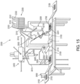
- Machine 1 can be incorporated into an overall system for preparing and analyzing specimens comprising body fluids or other biological samples containing cells, such as system 2000 shown in FIG. 15 and described below.
- Machine 1 can generally include, or form a portion of, a system that features a first station that obtains a specimen, a second station that applies the specimen to a substrate, third and fourth stations for fixing and staining the specimen, respectively, a fifth station that dries the specimen, a sixth station that images the specimen, and a seventh station for analyzing the images and data obtained from the specimen. Certain embodiments of machine 1 are compatible with system 2000; some embodiments of machine 1 can be used in other specimen preparation systems, and/or as stand-alone devices.
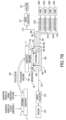
- Machine 1 can include or connect to a control system 5 as shown in FIG. 4 , which provides another perspective view of machine 1.
- Control system 5 can include one or more computers each containing a central processing unit capable of executing software instructions stored on computer readable media such as a hard drive, optical drive, or memory. Additionally, control system 5 can include electrical circuitry for executing the software instructions.
- Control system 5 can include a user interface for receiving user commands to control the operation of machine 1.
- Software stored on or provided to the computer can include programs that control the operation of components of machine 1 during specimen processing, such as fluid pumps and vacuums. For example, the software can include instructions for directing the machine 1 to apply various fixatives, stains, and rinses to the specimen, and to perform several agitation steps during specimen processing.
- control system 5 can also communicate via a network protocol (such as Appletalk ® , IPX, or TCP/IP).
- a network protocol such as Appletalk ® , IPX, or TCP/IP
- the network protocol may use cables (such as twisted pair cables) and/or a wireless connection such as WiFi.
- the control system may be connected to a laboratory information system using the network protocol.
- the laboratory information system can contain a server and/or database for storing information relating to specimens processed on machine 1.
- the database may contain a table that provides information about the person or source of the specimen (e.g., name, date of birth (DOB), address, time specimen was taken, gender, etc.), information relating to processing of specimen (processed on date ##/##/####, specimen number #, etc.), a copy of any images acquired of the specimen, and copies of any results obtained by analyzing the images.
- information about the person or source of the specimen e.g., name, date of birth (DOB), address, time specimen was taken, gender, etc.
- information relating to processing of specimen processed on date ##/##/####, specimen number #, etc.
- a copy of any images acquired of the specimen e.g., a copy of any images acquired of the specimen, and copies of any results obtained by analyzing the images.
- machine 1 can include supports 110A and 110B to secure the device to a location within a system or a laboratory workstation.
- Machine 1 also includes one or more substrate arms 10A and 10B, each connected at their base to an actuator 30A and 30B.
- the opposite ends of the substrate arms 10A and 10B include substrate grippers 20A and 20B for receiving and holding substrates during specimen processing.
- Each substrate gripper 20A and 20B receives and holds a substrate 2 while machine 1 completes all specimen processing steps (described below).
- the substrate may be or include a microscope slide, a cover slip, or other transparent material suitable for holding a specimen during specimen processing and microscopic examination after specimen processing.
- the embodiment of FIG. 1 depicts a glass microscope slide, substrate 2, which includes a biological specimen 3.
- substrate grippers 20A, 20B can hold the substrate 2 to substrate arms 10A, 10B during specimen processing.
- a suction tube 23 provides suction to the substrate grippers 20A and 20B through suction ports 21A and 21B, and 22A and 22B (note that ports 21A and 22A are positioned behind the slide 2 in FIG. 1 , and are shown in dashed lines).
- the machine 1 embodiment shown in FIGS. 1-3 is a dual substrate machine, capable of holding and processing a substrate on each of substrate arms 10A and 10B.
- Other embodiments provide for processing a single substrate or three or more substrates, sequentially or simultaneously.
- the embodiments depicted in FIGS. 1-6 use suction to attach the substrates 2 to the substrate arms 10A and 10B, alternative embodiments can use various types of clamps, fingers, or magnets (if the substrate is magnetized) to attach a substrate 2 to a substrate arm 10A during specimen processing.
- machine 1 receives a substrate 2 carrying a specimen 3 from an automated substrate mover 120 or manually from an individual.
- the substrate mover 120 can be a device that transports a substrate between stations (e.g., station 121 to station 122 to station 123, to station 124, and to station 125).
- FIG. 5 shows a system having a first label reader station 121, an applicator station 122, a staining station 123 that includes machine 1, a camera or imaging station 124, and a second label reader station 125.
- the first label reader station 121 is configured to read information from substrate 2 such as a bar code and/or "fingerprint" information that is used to identify the particular substrate 2 and specimen 3 thereon.
- the second label reader station 125 functions in the same manner, and the information it reads is used to verify that the specimen 3 that is imaged at station 124 is the same as the substrate that was processed.
- Substrate mover 120 can include a gripper 127 for holding the substrate 2, and registration circuitry or software to enable the mover 120 to determine whether the substrate 2 is mounted in the mover 120.
- substrate mover 120 can include a hydraulic cylinder for moving substrate 2 from a first station 121 to a second station 122. After specimen processing, the substrate mover 120 may remove the processed substrate from staining station 123 and transport the substrate 2 to another station for substrate examination, such as a microscope or station 124. Alternatively, an individual may manually remove a substrate from machine 1 after specimen processing.
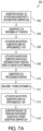
- FIG. 7A shows a flow chart 500 that includes a series of steps for moving substrate arms from an open position to a processing position.
- Flow chart 500 is further described below with reference to FIG. 7B , which shows a schematic diagram of machine 1.
- machine 1 in FIG. 1 is configured to accept and examine two substrates.
- reference may be made to only one set of components in machine 1 e.g., substrate gripper 20A, actuator 30A, substrate arm 10A, etc.
- the same steps, features, and attributes that are disclosed in connection with one set of components can also apply to the other set of components in machine 1 (e.g., substrate gripper 20B, actuator 30B, substrate arm 10B, etc.).
- machines for specimen examination such as machine 1 can include two or more than two sets of components, each set having some or all of the features discussed herein.
- step 502 of flow chart 500 substrate mover 120 places a substrate 2 in contact with a substrate gripper 20A.
- substrate 2 is positioned on the substrate gripper in a "specimen up” or “open” position.
- actuator 30A rotates substrate arm 10A by approximately 180° (see FIG. 7B ) to position substrate 2 in a "specimen down” or “specimen processing” or “closed” position (step 508), directly above platform 60A, so that substrate 2 is in a processing position in step 510.
- step 512 machine 1 stains specimen 3 positioned on substrate 2 by directing suitable fluids including stains, wash fluids, and fixatives to be pumped from reservoirs 210A, 211A, 212A, and 213A into contact with specimen 3 through ports 42A, 43A, 44A, and 45A. Excess fluids are removed from specimen 3 by vacuum pumping through ports 40A and 41A, and are collected in waste collectors 230 and 231.
- step 514 following staining of specimen 3, actuator 30A rotates substrate arm 10 by approximately 180° (reversing the rotation of step 506) to return the substrate to the "specimen up” position.
- substrate mover 120 removes the processed substrate from substrate gripper 20A.
- Other open or “specimen up” positions can also be used, provided that an operator or automated substrate mover can load and unload substrates from machine 1.
- the specimen up position can be rotated 100° or more (e.g., 120° or more, 130° or more, 140° or more) from the specimen processing position. In some embodiments, the specimen up position can be rotated less than 100° (e.g., less than 90°, less than 80°, less than 70°) from the specimen processing position, provided that an operator or substrate mover can load and unload substrates from machine 1.
- Actuators 30A and/or 30B may include an electric motor, pneumatics, magnetic systems, or other hardware (e.g., a worm gear) to move arm 10A and/or 10B.
- grippers 20A and 20B can each receive a substrate 2.
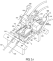
- actuators 30A and/or 30B then rotate arms 10A and/or 10B, and thus substrate 2, from the open ("specimen up") position to a processing position ("specimen down," as shown for arm 10B in FIG. 3A ) for application of fixative, stain, and rinse solutions, including agitation steps, and back to an open position for unloading after processing.
- FIG. 3A shows that actuator 30B has rotated substrate arm 10B from the open position depicted in FIG. 1 to a "closed" or processing position.
- FIG. 3A shows that the substrate 2 on substrate arm 10B has been flipped over and rotated approximately 180° from its loading position shown in FIG. 1 to a downward-facing position where specimen 3 on substrate 2 is substantially parallel to the surface of platform 60B.
- machine 1 applies various fixatives, stains, and rinses to specimen 3 on substrate 2 through several processing phases, which will be described in greater detail below.
- actuator 30B rotates substrate arm 10B back to the open position shown in FIG. 1 (both arms) and FIG. 3A (where only arm 10A is in the open position).
- control system 5 can detect the position of the arms utilizing one or more sensors 105A and 105B to detect indicator arms 101A and 101B (as shown in FIGS. 1 and 3 ).
- Sensors 105A and 105B can be proximity sensors, e.g., photoelectric sensors, utilizing, e.g., infrared light or various other technologies (lasers, motion detectors, etc.) to detect the presence or absence of the arms.
- proximity sensors 105A or 105B can have a detection field, and the sensors can determine whether or not a substrate arm (e.g., arm 10A and/or 10B) or a substrate gripper (e.g., gripper 20A and/or 20B) is within the detection field.
- a substrate arm e.g., arm 10A and/or 10B
- a substrate gripper e.g., gripper 20A and/or 20B
- Control system 5 can receive information from the sensors to determine the positions of substrate arms 10. For example, when substrate arm 10B (not shown in FIG. 3A ) is rotated to a processing position, proximity sensor 105B on the proximal end of indicator arm 101B senses target substrate gripper 20B, and notifies control system 5 that substrate arm 10B is rotated to a specimen processing position. In this position, proximity sensor 105B on the distal end of indicator arm 101B will not send a signal to control system 5, because the sensor does not detect any target (e.g., a substrate arm or substrate gripper).
- target substrate gripper 20B e.g., a substrate arm or substrate gripper
- proximity sensor 105B on the distal end of indicator arm 101B senses target substrate gripper 20B, and notifies control system 5 that substrate arm 10B is rotated to an open position. Stated differently, when substrate arm 10B has rotated away from the sensor 105B, the sensors send a "not present” signal to the control system 5. When arm 10B is rotated into the open position, arm 10B is closer to the sensor 105B, and the sensor can send a "present” signal to the control system 5. In alternate configurations, the sensor can be mounted on substrate 10B and can detect the presence of the indicator arm 101B.
- control system 5 can be used to calibrate the position of actuators 30A and 30B to known open and specimen processing positions, and/or to actively monitor the movement and position of substrate arms 10A and 10B based on control signals and/or feedback received from actuators 30A and 30B.
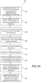
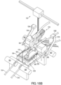
- FIG. 8A shows a flow chart 600 that includes an alternate series of steps for moving substrate arms from an open position to a processing position.
- Flow chart 600 is further described below with reference to FIG. 8B , which shows a schematic diagram of machine 1.
- step 602 of flow chart 600 substrate mover 120 places substrate 2 on substrate gripper 20A in a "specimen up” orientation. Then, in step 604, a first actuator 30A rotates substrate 2 by approximately 180° in a plane perpendicular to the plane of FIG. 8B , so that substrate 2 remains oriented in a "specimen up” position above platform 60A. In step 606, a second actuator 35A receives substrate 2 oriented in the "specimen up” position. Then, in step 608, second actuator 35A (e.g., positioned between substrate arm 10A and substrate gripper 20A) rotates the substrate 2 into a "specimen down” orientation. Second actuator 35A can also move substrate 2 downward toward platform 60A so that substrate 2 contacts offsets 70A and 70B.
- a first actuator 30A rotates substrate 2 by approximately 180° in a plane perpendicular to the plane of FIG. 8B , so that substrate 2 remains oriented in a "specimen up” position above platform 60A.
- step 610 machine 1 stains specimen 3 on substrate 2 by applying stains, fixatives, and wash solutions as discussed above in connection with step 512 of flow chart 500.
- second actuator 35 A rotates substrate 2 from a "specimen down" orientation to a "specimen up” orientation (step 614), and then first actuator 30A rotates substrate 2 by approximately 180° (e.g., in a plane perpendicular to the plane of FIG. 8B , reversing the rotation applied in step 606) so that the substrate remains oriented in a "specimen up” position.
- substrate mover 120 removes the processed substrate from substrate gripper 20A.
- machine 1 may include one or more (e.g., two, three, four, five, or more than five) platforms 60A and 60B as shown in FIGS. 1-3 for specimen processing.
- platform 60A can include lateral sides for supporting a top side of the platform.
- a shield 100 shown in FIGS. 1 and 3 , can be positioned between the platforms 60A and 60B to prevent fluids from splattering between the platforms 60.
- shield 100 can be formed from a transparent material that blocks fluids from one of platforms 60A and 60B from contaminating the other platform.
- shield 100 can be formed from a material that is translucent or opaque.
- shield 100 is depicted as being formed from a transparent material to allow other components positioned behind shield 100 to be shown in the same figure.
- Shield 100 could also have been shown as being formed from an opaque material, in which case portions of some components such as platform 60A and block 80A would have been obscured.
- FIG. 3B shows an indexing mechanism 50A that can be used to translate the machine 1 to provide substrates 2 from each of the substrate grippers 20A, 20B to a position for specimen processing.
- the indexing mechanism 50A can be in many forms, such as electromechanical devices (e.g., a rack and pinion gear set powered by an electric motor), linear actuators (e.g., pneumatic actuators, hydraulic actuators, or electromagnetic actuators).
- electromechanical devices e.g., a rack and pinion gear set powered by an electric motor
- linear actuators e.g., pneumatic actuators, hydraulic actuators, or electromagnetic actuators
- the indexing mechanism 50A translates the machine 1 linearly between two positions, other translation paths are possible based on the number of platforms included on the machine 1, and their configuration and layout, such as circular or semi-circular (e.g., an indexing table that can move in an arcuate path).
- the indexing mechanism 50A can include a gear rack 50B attached to a base 50C of the machine 1 and a pinion gear 50D attached to an electric motor 50E that is fixed to the base 50C.
- the machine 1 can be attached to the base 50C using one or more sliding devices 50F so that the machine 1 can move smoothly when translated by the indexing mechanism 50A.
- the indexing mechanism 50A can move the machine 1 so that the multiple substrate grippers 20A and/or 20B of the machine 1 to receive a substrate 2 from a substrate mover 120 (shown in FIG. 5 ) so that a sample disposed on the substrate 2 can be prepared by the machine 1, and also so that, once prepared, the substrate gripper 20A and/or 20B can provide the substrate 2 having a prepared sample can be provided to the substrate mover 120 for sample processing.
- substrates 2 are typically provided to, and from, the substrate mover 120 in an alternating manner.
- a first substrate 2 is provided from the substrate mover 120 to a first substrate gripper 20A, to be processed at a first platform 60A, while the machine 1 is in a first position.
- the indexing mechanism 50A can translate the machine 1 to a second position so that a second substrate gripper 20B can receive a second substrate, to be processed at the second platform 60B, from the substrate mover 120.
- the indexing mechanism 50A can translate the machine 1 back to the first position so that the substrate mover 120 can remove the first substrate 2 from the first substrate gripper 20A. Once the substrate 2 is removed from the first gripping platform 20A, a next substrate can be provided to the first gripping platform 20A.
- This method for providing substrates to alternating gripping platforms can be implemented for more than two (e.g., three, four, five, or more than five) platforms thereby increasing throughput of specimens prepared for further evaluation.
- Platforms 60A and 60B are typically formed from one or more materials that are relatively chemically inert with respect to the fluids used during specimen processing and provide a suitable surface tension.
- Exemplary materials that can be used to form platforms 60A and 60B include engineering thermoplastics, such as polyoxymethylene (e.g., Delrin ® manufactured by DuPont), high molecular weight fluorocarbons, such as polytetrafluoro ethylene (PTFE) (e.g., Teflon ® manufactured by DuPont), and metals such as aluminum, steel, and titanium, provided they are manufactured and/or treated to provide a suitable surface tension that acts to assist in evenly distributing and confining the processing fluids to the space between substrate 2 and the platforms, and allowing suitable evacuation of the processing fluids as well.
- the platforms can also advantageously reduce or minimize the formation of bubbles or spaces within the fluids as they are distributed, and at the same time maintain a sufficient surface tension such that fluid leakage out of the separation between the platforms and substrate 2 is reduced or
- the surface area of platforms 60A and 60B can be selected as desired for purposes of substrate handling and fluid delivery. Factors such as the surface area of platforms 60A and 60B can also influence the selected surface area of substrate 2.
- the surface area of platform 60A e.g., the area of the surface of platform 60A that faces substrate 2
- the surface area of platform 60A is slightly smaller than the area of the surface of substrate 2 that faces platform 60A.
- the area of the surface of substrate 60A that faces substrate 2 is smaller than the area of the surface of substrate 2 by 2% or more (e.g., 3% or more, 5% or more, 7% or more, 10% or more, 15% or more, 20%> or more, 25% or more, 30% or more).
- Platforms 60A and 60B can be attached to blocks 80A and 80B, respectively.
- Block 80A includes lateral sides 81A-84A supporting a top side 85A as shown in FIG. 2 .
- Blocks 80A and 80B can be made of the same or similar materials to those used for the platforms, including metals, ceramics, and/or plastics.
- materials such as Delrin ® can be used to form blocks 80A and 80B, particularly in embodiments that implement Romanowsky staining of specimens.
- Other materials that can be used in embodiments include metals, and Teflon ® brand polytetrafluoroethylene-coated aluminum, steel, or titanium.
- platforms 60A and/or 60B can be raised as shown in FIGS. 1-3 .
- platforms 60A and/or 60B can be flush with the upper surface of blocks 80A and 80B, respectively.
- certain features of machine 1 as well as surface tension of fluids and surface energy of the platform or block prevent excess fluids from flowing past the edges of platforms 60A/60B and/or blocks 80A/80B.
- platform 60A can include offsets 70A-70D to provide a separation between the surface of platform 60A and substrate 2, and prevent substrate 2 from contacting platform 60A.
- Platform 60B can include a corresponding set of offsets 71A-71D. Offsets can include standoffs, pins, pegs, rods, beads, walls, or other structures that provide separation between the surface of platform 60A and/or 60B and substrate 2. Offsets 70A-70D and 71A-71D ensure that the surfaces of platforms 60A and 60B and substrate 2 remain substantially parallel when substrate 2 contacts the offsets. The benefit of maintaining these two surfaces in parallel is that the volume enclosed between these two surfaces is thus defined and can be precisely controlled. If the two surfaces are not substantially parallel, and the angle between them changes, then the volume between them also changes and is not fixed and precisely controlled. In addition, the fluids may not apply uniformly to the specimen if such two surfaces are not substantially parallel.
- the phrase "substantially parallel” means that two surfaces are exactly parallel or nearly parallel, so that imperfections in the surface flatness of substrate 2 are reduced or eliminated when substrate 2 contacts the offsets. For example, although great care is taken in the production of substrates, certain substrates may have imperfections such as twist and/or non-coplanar corners. In the systems and methods disclosed herein, the use of offsets assists in correcting these imperfections by improving the surface flatness of substrate 2 where needed, orienting substrate 2 in a substantially parallel relationship to platforms 60A and 60B in the process.
- the phrase "substantially parallel” covers situations in which the two surfaces are not perfectly flat, but the offsets are all the same size or height, so that at least the contact points of a surface of the substrate with the offsets are in the same plane.
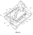
- FIG. 6A shows substrate 2 with specimen 3 (specimen not shown), substrate gripper 20B, blocks 80A, 80B, platforms 60A, 60B, offsets 70A-70D and 71A-71D, and separation 92 between substrate 2 and platform 60B.
- Separation 92 allows fluids to travel between the surface of platform 60B containing ports 40B-45B and substrate 2 containing specimen 3.
- the separation distance required for optimal specimen fixing, staining, and rinsing will vary depending on the flow rate of fluids dispensed from ports 40B-45B (and/or ports 40A-45A), port diameter, the viscosity of the fluids applied during processing, and the amount of suction available for removing fluids from the substrate, separation, and platform.
- offsets providing a separation 92 of about 100-200 microns between the surface of platform 60B and substrate 2 enable fixing, staining, and rinsing for specimens comprising blood cells in embodiments capable of dispensing fluids at flow rates ranging from 70 to 140 microliters per second (e.g., 90, 115, or 125 microliters per second) from ports 40B-45B having a diameter ranging from 500 to 1,500 microns.
- the size or height of separation 92 can vary from about 50 microns to 1,000 microns for certain embodiments (e.g., from about 50 to 500 microns, from about 75 to 250 microns, from about 100 to 200 microns), provided such embodiments are capable of overcoming surface tension from fluids in the separation while dispensing and removing fluid during specimen processing.
- the diameters of ports located on platform 60A and/or 60B can vary from about 125 microns to 5,000 microns.
- FIGS. 6B and 6C show a ball joint mechanism 25 that can be used to align a substrate gripper 20A to be parallel with a platform 60A.
- the ball joint mechanism 25 can include a ball member 25A that is rigidly fixed to the substrate gripper 20A, a deflection element 25B (e.g., a spring), a lower socket 25C that is rigidly connected to the substrate arm 10A, an upper socket 25D, a cap 25E that is fixed to the lower socket 25C (e.g., using fasteners), and a set screw 25F.
- the ball joint mechanism 25 can be adjusted to compensate for any misalignment that may be present due to tolerance stack-up or fabrication problems.
- the set screw 25F is loosened and the substrate arm 10A is moved to the closed position. Since the set screw 25F is loosened, the substrate gripper 20A, while gripping a substrate 2, is able to lay substantially parallel to the platform 60A while the substrate 2 positioned along the contact offsets 70.
- the number of offsets on platform 60 can be reduced or eliminated completely; a shim with a thickness corresponding to the desired separation distance can be used temporarily during set up or calibration of machine 1 in conjunction with ball joint mechanism 25 to set separation 92 at a desired distance for specimen processing.
- the ball joint mechanism 25 is loosened, the deflection element 25B applies a force to keep the substrate gripper 20A semi-fixed to the substrate arm 10A so that it is able to move independently, but it is not so loose and not free to move so much as to interfere with, or cause damage to, other components of the machine 1.
- the set screw 25F can be tightened to secure the ball joint mechanism 25. As shown, when tightened, the set screw 25F applies a downward force on the upper socket 25D and thus applies a frictional force to the top of the ball member 25A via the upper socket 25D. Since the lower socket 25C is fixed to the cap 25E, the force created by the set screw 25F also lifts the lower socket 25C such that the lower socket 25C applies a frictional force to the bottom side of the ball member 25A to constrain the ball member 25A within the upper and lower sockets 25C, 25D. Once constrained to the ball member 25A, the substrate gripper 20A becomes fixed to the substrate arm 10A.
- the ball joint mechanism 25 need not be adjusted again during normal use. However, if the substrate gripper 20A becomes misaligned and therefore the ball joint mechanism 25 requires adjustment (e.g., due to damage, machine repair, poor performance, or other reasons), the set screw 25F can be loosened, the substrate gripper 20A can be moved to a closed position to position so that a substrate gripped by the substrate gripper 20A is substantially parallel to the platform 60A, and then set screw 25F can be tightened to secure the ball joint mechanism 25.
- actuators 30A and/or 30B can be configured to adjust the position of substrate arms 10A and/or 10B to vary the extent of separation between the surface of platforms 60A and/or 60B and substrate 2. Varying this separation provides greater flexibility in embodiments that allow for adjusting the fluids assigned to each port, flow rates, fluid viscosities, and evacuation forces from platforms 60A and/or 60B.
- a 100 micron separation 92 can provide sufficient specimen fixing, staining, and rinsing when fluids applied from platform 60A are dispensed at a flow rate of 70 microliters per second from ports 40A-45 A having port diameters ranging from 500 microns to 1,500 microns.
- a higher flow rate for fluids dispensed from ports 40A-45A such as 115-140 microliters per second, can be used for specimen processing.
- machine 1 may contain a series of ports and tubes for dispersing and removing fluids applied during specimen processing.
- the following discussion describes various ports, tubes, and other components associated with platform 60A, but similar considerations apply to platform 60B and its associated components.
- FIG. 2 shows a close up view of the apparatus shown in FIG. 1 , and shows in detail ports 40A-45A on platform 60A and tubes 50A-55A connected to block 80A.
- Tubes 52A-55A distribute certain fluids including one or more fixatives, stains, and rinse solutions across the platform, into the separation, and onto the substrate.
- the top side of platform 60A includes six ports 40A-45A that are connected to tubes 50A-55A. Fluids are driven by one or more pumps through the tubes and ports onto substrate 2.
- One or more fluid reservoirs 210A-213A (such as a first stain reservoir 211A, a second stain reservoir 212 A, a fixative reservoir 210A, and a rinse solution reservoir 213A), e.g., as shown in FIG. 4 , can direct fluid onto platform 60A and substrate 2.
- the diameters of ports 40A-45A shown in FIGS. 1-3 range from approximately 500 microns to 1,500 microns, although the diameters can also be smaller or larger in certain embodiments. In some embodiments, the diameters of the vacuum ports 40A and 41 A are more than twice the diameters of fluid ports 42A-45 A.
- Each of ports 40A-45A is typically dedicated to a particular fluid or vacuum source. Alternatively, more than one port may be used for each fluid or vacuum source, or multiple tubes from various fluid and vacuum sources may connect to a single port located on platform 60A. For example, in some embodiments, only one port on platform 60A may be used for waste removal, but when using more viscous fluids, the single port may not provide sufficient suction to evacuate residual fluid from the platform. Thus, it may be desirable in certain embodiments to provide two suction ports at different positions on the platform (e.g., one suction port at each end of the platform) for removing excess stain, fixative, and rinse fluids as shown with ports 40A and 41A in FIG. 2 .
- a single port on platform 60A may be dedicated for a particular stain, while in other embodiments multiple ports are used for applying stains during specimen processing. Indeed, various combinations relating to the number of ports, port locations, and fluids assigned to each port and fluid tube may be used in different embodiments of the invention.
- Ports 40A-45 A can generally be positioned as desired on platform 60A to provide for fluid delivery to, and fluid removal from, substrate 2.
- each of the fluid ports is positioned on platform 60A such that the port's aperture is not positioned directly adjacent or beneath specimen 3 on substrate 2 when the specimen is undergoing processing.
- a larger quantity of stain may be applied to cells in that portion (in the vicinity of the port) than to cells in other portions of the specimen.
- fluid ports that deliver stain to specimen 3 can be spaced a certain distance from the specimen-containing area of a slide to improve staining results.
- pairs of ports e.g., multiple pairs of ports, located opposite each other, can also improve staining uniformity.
- two ports are used to deliver stain to specimen 3.
- the two ports can be located on platform 60A at positions spaced a certain distance (e.g., are offset) from the edges of specimen 3, and located opposite each other in a direction parallel to the short edges of platform 60A.
- stain is dispensed from the two spaced ports, a relatively uniform quantity of stain is deposited on the cells in different regions of specimen 3, and improved staining homogeneity is observed in specimen images.
- ports 40A-45A can generally be positioned as desired to remove excess fluids from the surface of substrate 2 using one or more vacuum sources
- ports that are used for fluid removal are spaced at a distance from positions on platform 60A that are directly beneath cells within specimen 3 on substrate 2. Positioning waste removal ports in this manner (i.e., not directly opposing a portion of specimen 3) reduces the chances that when such ports are actuated to evacuate fluids from substrate 2, cells from specimen 3 are inadvertently damaged or drawn into the fluid removal ports.
- the waste removal ports are spaced apart from the edge of the specimen area and arranged opposite each other along a direction parallel to the long edges of platform 60A.
- Fluid tubes 52A-55A and 52B-55B can be positioned to deliver fixative to platforms 60A and 60B, separation 92, substrate 2, and specimen 3 during specimen processing.
- Fixatives that can be used include chemicals used for protecting biological samples from decay, and such fixatives can impede biochemical reactions occurring in the specimen and increase the mechanical strength and stability of the specimen.
- Various fixatives can be used including, but not limited to, methanol, ethanol, isopropanol, acetone, formaldehyde, glutaraldehyde, EDTA, surfactants, metal salts, metal ions, urea, and amino compounds.
- one or more fluid tubes 52-55A can be connected to a port inside platform 60A and a respective fixative reservoir 210A.
- the fluid tubes may also include a connection to a pump 200A and/or a valve capable of directing fixatives from the reservoir through the tube and a port located on the platform, and onto a substrate and specimen.
- pump 200A can direct fixative from reservoir 210A through tube 54A, through block 80A, out from port 44A, onto platform 60A, into the separation 92 between the platform 60A and substrate 2, and onto substrate 2 containing specimen 3.
- a vacuum or other suction source 220A and/or 221A can evacuate residual fixative from platform 60A, the separation 92, and substrate 2 into waste container 230A and/or 231A via one or more of ports 40A and/or 41A through waste tubes 50A and 51A.
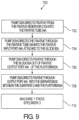
- FIG. 9 shows a flow chart 700 that includes a series of steps for applying fixative to a specimen.
- a pump e.g., pump 200A
- fixative e.g., methanol
- a reservoir e.g., reservoir 210A
- a fixative tube e.g., tube 54A
- the fixative is directed into port 44A attached to block 80A.
- the fixative is directed out of port 44A in platform 60A.
- the fixative is directed out through port 44A and into separation 92 between substrate 2 and platform 60A.
- step 710 specimen 3 on substrate 2 is fixed by the fixative solution.
- pump 200A directs methanol through tube 54A and port 44A, onto platform 60A and into the separation 92 at a flow rate of 70 microliters per second for a period of four seconds.
- a vacuum or other suction source 220A and/or 221 A then removes residual methanol present in separation 92 and/or on the platform 60A and substrate 2 using ports 40A and/or 41 A and waste tubes 50A and/or 51A (further described below).
- the pump 200A can again direct methanol through tube 54A and port 44A, and onto platform 60A at a flow rate of 70 microliters per second for a period of four seconds, followed by a second fluid evacuation process.
- machine 1 is capable of varying the frequency and flow rates for each fixing phase. Other flow rates sufficient to overcome any surface tension in the fluid located in separation 92 and fix specimen 3 for further processing and evaluation can also be used.
- machine 1 can achieve optimal fixation for various specimens using several different fixatives.
- Machine instructions for different types of specimens can be hardwired or preprogrammed in control unit 5 and selected by a system operator as needed.
- fixatives can be applied to specimens during fixative phases. For example, 85% methanol can be used as the fixative. For some stains, an ethyl alcohol or formaldehyde based fixative can be used. Additional fixative formulations that can be used to prepare the specimen are disclosed, for example, in U.S. Provisional Patent Application No. 61/505,011 .
- Machine 1 also includes tubes and ports configured to apply one or more dyes or stains to a specimen fixed to a substrate in one or more staining phases. Staining a specimen increases the contrast of the specimen when it is viewed or imaged under a microscope or other imaging device.
- Romanowsky stains and/or other dyes or stains can be used, including hematoxylin and eosin, fluorescein, thiazin stains using antibodies, nucleic acid probes, and/or metal salts and ions. Additional stain formulations that can be used to prepare the specimen are disclosed, for example, in U.S. Provisional Patent Application No. 61/505,011 .
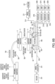
- FIG. 10 is a flow chart 800 that includes a series of steps for applying stain to a specimen.
- a pump e.g., pump 201A
- a stain tube e.g., tube 52A
- the stain is directed into a port (e.g., port 42A) attached to block 80A.
- the stain flows out of port 42A in platform 60A.
- the stain flows into separation 92 between substrate 2 and platform 60A and thereafter, in step 810, stains specimen 3 on substrate 2.
- multiple tubes and ports can be used to apply stain to specimen 3.
- a second pump e.g., pump 202A
- stain e.g., the same stain or a different stain from that dispensed from reservoir 211A
- two or more fluid tubes may connect to a shared stain reservoir or pump and/or valve used to direct stain through the ports and onto the platform.
- tube 52A may deliver red stain, such as a fluorescein dye, to the platform, substrate 3, and specimen 2.
- Tube 53A may deliver blue stain, such as a thiazin dye.
- the numbers, locations, and sizes of the ports on platform 60A are selected to optimize the application of stain to a specimen fixed to the substrate. If other stains are selected, a different number, locations, and sizes of ports may be preferable depending on the viscosity of the stain.
- Each of ports 40A-45A can include both an input channel for receiving fluid and an output channel for outputting fluid.
- the output channels of the rinse 45A, fixative 44A, and staining ports 42A-43A are on the upper surface of platform 60A, and the input channels of vacuum ports 40A and 41A may be on opposite ends of the upper surface of platform 60A.
- the input channels of the rinse 45A, fixative 44A, and staining ports 42A-43A may be situated on the same lateral side of block 80A, and the output channels of the vacuum ports 40A and 41A can be positioned on opposite lateral sides of block 80A.
- control system 5 instructs a pump (e.g., pump 201A) in step 802 to direct a stain (e.g., a stain comprising fluorescein dye) from a stain reservoir into fluid tube 52A.
- a stain e.g., a stain comprising fluorescein dye
- the stain enters port 42A from the fluid tube.
- the stain leaves port 42A at a flow rate of 140 microliters per second, for a five second period, and in step 808, the stain is deposited into separation 92 between platform 60A and substrate 2 containing specimen 3.
- step 810 specimen 3 on substrate 2 is stained.
- a vacuum or other suction source may then evacuate residual stain present in separation 92, on platform 60A, and on substrate 3 using ports 40A-41A and waste tubes 50A-51A.
- Machine 1 can be programmed to repeat these staining and evacuation phases after a delay (e.g., a delay of between 3 seconds and 10 seconds, such as a five second delay), following the first staining phase.
- a second pump 202A can be instructed by control system 5 to direct thiazin dye from a stain reservoir through fluid tube 53A, out port 43A at a flow rate of 140 microliters per second, and onto platform 60A for a period of time, e.g., three seconds.
- a vacuum or other suction source e.g., pump 220A and/or 221) may then evacuate residual thiazin dye present in separation 92 and/or on platform 60A and/or on substrate 2 using ports 40A-41A and waste tubes 50A-51A.
- machine 1 is capable of varying the frequency, delay times, and flow rates for each staining phase.
- the flow rate may range, e.g., from 70 to 140 microliters per second, or may be smaller or greater than the outer limits of this range (e.g., 10 to 500 microliters per second) provided the flow rate is sufficient to overcome any surface tension present in the fluid located in separation 92 and desirably stain the specimen for the intended evaluation.
- Exemplary stains that can be applied to specimens include, but are not limited to: Wright-Giemsa stain, Giemsa stains, and Romanowsky stains.
- Other agents such immunocytochemical reagents or other markers of specific cell components can also be applied to specimens.
- a vacuum or other suction source 220 and/or 221 can evacuate residual fluid from substrate 2, separation 92, and platform 60A during or between fixing and staining phases.
- one or more waste tubes can be connected to sides 82A and 84A of block 80A.
- Waste or vacuum tubes 50A and 51 A are used to withdraw fluid and small particulate matter from platform 60A, separation 92, and substrate 2 into a waste container or other location separate from machine 1.
- waste tubes 51A and 51B may be connected to separate vacuum sources 220 and 221, and waste containers 230 and 231, at the distal ends of the waste tubes.
- two or more waste tubes can be connected to a single vacuum source, and the same waste container, as shown in FIG. 4 .
- Waste tubes 50A and 50B may extend through pinch valves 90A and 90B, respectively.
- a vacuum or other source for applying suction may be connected to one or more of waste tubes 50A, 50B, 51A, and 51B to draw fluid from the platforms 60A and/or 60B, separation 92, and substrate 2 into waste containers 230 and 231.
- the vacuum force applied within the waste tubes may be equivalent to negative one to negative ten pounds per square inch ("psi") to provide sufficient suction for removing fluids when the separation between the substrate 2 and the platform is between 100 to 200 microns.
- psi pounds per square inch
- negative pressure refers to a pressure less than the ambient pressure within machine 1 or the environment surrounding machine 1.
- the environment surrounding machine 1 has an ambient air pressure of approximately one atmosphere.
- Negative pressures refer to pressures that are less than this ambient air pressure (e.g., a pressure of negative one psi applied to a fluid is a pressure of one psi less than the ambient air pressure exerted on the fluid).
- Other vacuums ranging from negative 0.1 psi to negative 14 psi (e.g., negative six psi), or greater, can be used provided such vacuums are sufficient to overcome any surface tension in the fluid present in the separation and remove all residual fluid in the separation and on the substrate and specimen.
- actuator 30A can raise the proximate edge of substrate 2 a distance of 15-35 microns from the specimen processing position. This increased separation between substrate 2 and platform 60 can improve evacuation of any residual fluids in separation 92 during a vacuum phase.
- control system 5 is configured to vary the frequency and vacuum applied for fluid removal during specimen processing.
- FIG. 11A includes a flow chart 900 that features a series of steps for removing excess fluid from a substrate. Following a fixing phase, for example, control system 5 can open pinch valves 90A and/or 90C in step 902 and apply a vacuum of negative 5 psi in the waste tubes (e.g., waste tubes 50A and 51A) for a five second period. During this period, fixative is removed (step 904) the separation, substrate, and platform through ports 40A and 41A. The fluid travels through the waste tubes in step 906, and is deposited in into one or more waste containers (e.g., containers 230 and/or 231) in step 908.
- waste containers e.g., containers 230 and/or 231
- control system 5 can instruct one or more of the pinch valves 90A, 90C to close off the waste tubes 50A and/or 51A in step 910, thereby preventing further evacuation by the vacuum 220-221.
- Control system 5 may direct machine 1 to repeat this fluid removal step after each fixing phase.
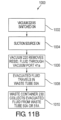
- FIG. 11B includes a flow chart 1000 that features an alternate series of steps for removing excess fluid from a substrate.
- the method in flow chart 1000 does not use pinch valves to seal waste tubes. Instead, after a fluid application phase, suction source 220 and/or 221 are initialized in step 1002 and enter an active state in step 1004.
- the suction source applies a vacuum of negative 3 psi in waste tubes 50A and/or 51A for a four second period to remove fluid from separation 92, substrate 2, and platform 60A through ports 40A and 41A in step 1006.
- the evacuated fluid travels through waste tubes 50A and/or 51A in step 1008, and is deposited in one or more waste containers 230, 231 in step 1010.
- Machine 1 may repeat this fluid removal step after each fluid application phase. By varying the frequency and pressure applied during fluid removal steps, machine 1 may achieve optimal fixing, staining, and rinsing of biological specimens.
- Pinch values 90A, 90B, 90C, and 90D close off waste tubes 50A, 50B, 51A, and 51B, as shown in FIG. 1 .
- the pinch valves 90A-90D may be mechanically, electrically, hydraulically, or pneumatically actuated through actuators contained within or external to the valves. Pinch valves 90A-90D operate to prohibit fluid flow through waste tubes 50A, 50B, 51A, and 51B. For example, when changing or emptying a full waste container 230 from machine 1, it may be desirable to close the pinch valves (90A-90D) to prevent leakage of residual fluids present in the waste tubes. Different valve types or other mechanisms such as clamps or stoppers may be used with embodiments of machine 1 to close the waste tubes 50A, 50B, 51A, and 51B.
- Rinse solutions can be applied during specimen processing with machine 1 in one or more rinse phases. For example, it may be desirable to remove residual and/or excess fluids from specimen 3 on substrate 2, separation 92, and platforms 60A and/or 60B between fixing phases, between staining phases, and/or between fixing and staining phases.
- Rinse solutions compatible with the present systems and methods include distilled water; buffered, aqueous solutions; organic solvents; and mixtures of aqueous and organic solvents, with or without buffering. Additional formulations for rinse solutions that can be used to prepare the specimen are disclosed, for example, in U.S. Provisional Patent Application No. 61/505,011 .
- FIG. 12 includes a flow chart 1100 featuring a series of steps for rinsing a specimen.
- a pump e.g., pump 203A
- rinse solution e.g., comprising distilled water
- a rinse tube e.g., rinse tube 55A
- the rinse solution enters port 45A connected to block 80A.
- the rinse solution flows onto platform 60A through the output channel of port 45A, and in step 1108, the rinse solution enters separation 92 between substrate 2 and platform 60A.
- a vacuum source 220, 221 applies suction to one or more of waste tubes 50A and 51A to remove rinse solution from separation 92 and substrate 2; the rinse solution is transported to waste container 230 and/or 231.
- control system 5 may direct pump 203A to apply the rinse solution at a flow rate of, e.g., 70 microliters per second for a period of, e.g., five seconds.
- control system 5 may vary the duration and flow rate of each rinse phase and the number of rinse phases.
- control system 5 may adjust the placement of one or more rinse phases during specimen processing. Control system 5 may, for example, direct that a rinse phase occur once, after completion of all fixing phases, and that a second rinse phase occur once, after completion of all staining phases.
- rinse phases may be interspersed between two or more fixing phases or between two or more staining phases.
- Specimen processing in certain embodiments may include one or more agitation phases to disperse fixative, stain, and/or rinse fluids throughout separation 92, substrate 2 containing specimen 3, and platforms 60A and/or 60B during the fixing, staining, and/or rinsing phases.
- FIG. 13 includes flow chart 1200 that features a series of steps for agitating a specimen. Actuator 30A and/or 30B, shown in FIG. 3A , can provide fine movement adjustment for changing the position of substrate 2 relative to platform 60A and/or 60B.
- Control system 5 can include software and/or hardware for instructing the actuator 30A and/or 30B to initiate an agitation phase.
- Actuator 30A and/or 30B can be configured to move substrate arm 20A and/or 20B up and down upon an agitation initiation command from the control system.
- the agitation phase may repeat for a predetermined number of agitation cycles.
- the term "agitation cycle,” as used herein, refers to motion from a starting position in an upward direction, followed by movement in a downward direction opposite to the upward direction.
- one or more agitation cycles return substrate 2 to the starting position at the conclusion of each cycle, or at least at the conclusion of some cycles.
- substrate 2 does not return to the starting position at the conclusion of some or all of the agitation cycles, but each cycle still includes an upward motion followed by a downward motion.
- Actuator 30A and/or 30B typically continues moving substrate 2 in one or more agitation cycles until a stop command is sent to the actuator from the control system 5.
- An agitation phase may temporarily increase the separation size (separation distance) between substrate 2 and the surface of platform 60A and/or 60B, and then return the substrate to the specimen processing position.
- an agitation phase may include a series of movements that shift substrate 2 between an angular position relative to the surface of platform 60A and/or 60B and the specimen processing position. Surface tension in the fluids dispensed into the separation between the platform and substrate 2 causes a redistribution of fluid molecules on the substrate when the substrate moves from the specimen processing position during the agitation phase and can advantageously improve fluid distribution across the specimen.
- the positions of one or more of offsets 70A-D and/or 71A-D can be rapidly adjusted to agitate specimen 3.
- the positions of platforms 60A and/or 60B can be adjusted to cause agitation of specimen 3.
- platforms 60A and/or 60B can be moved alternately up and down (e.g., corresponding to the direction of movement of substrate 2 described above) to cause agitation of specimen 3.
- agitation of specimen 3 can be effected by varying the extent to which actuator 30A and/or 30B drives substrate 2 towards offsets 70A-D and/or 71A-D when the substrate arms are made of a material that flexes, as discussed below.
- Strain gauges can be used to measure and adjust the frequency of the agitation applied to substrate 2 by detecting the variation in strain in the substrate arms as a function of time.
- an agitation phase is initiated.
- control system 5 instructs actuator 30A to begin an agitation cycle.
- actuator 30A rotates substrate 2 upward in step 1206, increasing the distance between substrate 2 and platform 60A.
- step 1208 actuator 30A rotates substrate 2 downward toward platform 60A, reducing the distance between the substrate and platform 60A.
- decision step 1210 if the agitation phase is to continue, control returns to step 1204 and the rotation of substrate 2 by actuator 30A occurs again in another agitation cycle. If the agitation phase is to terminate, then control passes from step 1210 to step 1212, where substrate 2 is returned to its initial position with agitation complete.
- the agitation phase can include one or more agitation cycles applied through actuator 30A and/or 30B. Further, agitation phases can occur once or multiple times during each of the fixative, stain, and/or rinse phases and in varying frequencies between each of the fixing, staining, and/or rinsing phases. For example, and referring to FIG. 3A , actuator 30A and/or 30B may raise the proximate edge of substrate 2 vertically a distance of 35 microns from the specimen processing position and subsequently return substrate 2 to the specimen processing position three times, once after each fixing, staining, and rinse phase.
- Actuator 30A and/or 30B may complete each agitation cycle in two seconds (e.g., one second to raise the proximate edge of substrate 2 vertically a distance of 35 microns from the specimen processing position and one second to return the substrate to the specimen processing position).
- Machine 1 is capable of carrying out instructions to vary the agitation frequency and distance for each agitation cycle and/or phase.
- an agitation phase may include actuator 30A and/or 30B raising the proximate edge of substrate 2 vertically a distance of 5 microns from the specimen processing position and then returning the substrate to the specimen processing position, 10 to 20 times per second.
- the agitation distance is 5 microns or more (e.g., 15 microns or more, 25 microns or more, 50 microns or more, 100 microns or more, 150 microns or more, 200 microns or more, 250 microns or more, 300 microns or more, 500 microns or more, 700 microns or more, 1 mm or more.
- the agitation distance is between 35 microns and 350 microns.
- the agitation cycle frequency is one cycle per second or more (e.g., two cycles per second or more, three cycles per second or more, four cycles per second or more, five cycles per second or more, seven cycles per second or more, ten cycles per second or more).
- substrate gripper 20A and/or 20B may include an actuator that rotates the substrate about an axis perpendicular to the rotational axis of actuator 30A and/or 30B depicted in FIGS 1 and 3 .
- platform 60A and/or 60B may be equipped with an offset adjuster for raising or lowering the one or more offsets 70A-D and/or 71A-D during fixing, staining, and rinsing phases.
- platform 60A and/or 60B can include offsets that are attached to an internal plate in the platform. The height of the plate may be varied using an internal actuator, thus varying the height of the offsets.
- the position of the offsets 70A-D and 71A-D relative to substrate 2 can be changed by instructing the actuator to move platform 60A and/or 60B, or block 80A and/or 80B, thereby changing the separation distance during the agitation phase.
- Control system 5 can adjust the frequency of fluid cycles, flow rate, offset height, separation distance, and agitation parameters and frequency to process specimens more efficiently, using significantly less fluid volumes during the specimen preparation process as compared to conventional staining and preparing techniques.
- substrate arms may be made of a material that flexes such that if a substrate in the specimen processing position rests against only two offsets extending from the platform, an actuator or other motive force element may rotate the slide further towards the platform surface until the slide rests against all four offsets. Varying the position of the substrate between these two positions may accomplish sufficient agitation during specimen processing.
- Substrate arms may include strain gauges to monitor the strain in the substrate arm, and may be used to inform control system 5 of the position of the substrate relative to the platform offsets.
- the control system may include information corresponding to the thickness imperfections of the substrate, which the control systems may account for when placing the substrate in the specimen processing position or during agitation phases.
- the control system 5 can dry the specimen using a dryer 4 attached to machine 1.
- FIG. 14 includes a flow chart 1300 that features a series of steps for drying a specimen. Following the initial step 1302 in which the completion of the staining and other phases (e.g., one or more rinsing phases) is verified, in step 1304 the dryer 4 directs a flow of air across the specimen. The drying process continues in step 1306, until a signal is received from the control unit to stop the drying. When the signal is received, the dryer stops the flow of air across the specimen and the drying phase terminates at step 1308.
- machine 1 can be controlled to vary the temperature of the air, the flow rate, the duration of the applied air flow, and the phase(s) during specimen processing for drying the specimen 3.
- dryer 4 can direct a flow of air at approximately 120° F at a rate of 10 liters per minute for a period of 7 seconds across the specimen.
- Other air temperatures e.g., ambient temperature up to 300° F
- air flow rates e.g., one liter per minute to 100 liters per minute
- air flow periods e.g., from a few seconds to several minutes
- FIG. 15 shows a schematic diagram that illustrates one possible embodiment of a specimen examination system 2000.
- System 2000 includes a platform 2100, a light receiving device 2200, a computer 2300, an applicator 2400, a gas circulation device 2500, a light source 2600, a dispenser 2800, a discharge device 2900, a slide labeler 3000, and slide label reader 3100.
- An advancer 2110 may be configured to receive one or more slides or other substrates 2700.
- the advancer 2110 may be attached to a surface, such as the top surface 2101, of the platform.
- the advancer 2110 may take the form of a belt, and the system may use a mechanical arm, gravity, magnetism, hydraulics, gears, or other locomotion techniques to move substrate-mounted specimens along the surface 2101 of the platform.
- the platform 2100 may also include a feeder 2102 and a collector 2106 for respectively feeding and collecting substrates 2700 (e.g., slides) from or to a stack or rack.
- Feeder 2102 may be equipped with a feeder propulsion mechanism 2103 (such as rubberized wheels) for pushing the specimens onto advancer 2110.
- a mechanical arm could be used to grab substrates 2700 and place the substrates on the advancer directly.
- Alternate mechanisms to propel the substrates out of feeder 2102 may be used such as magnets or hydraulics.
- the feeder may include a sensor for determining how many slides are present. The sensor could measure the weight of substrates 2700 for example to determine how many substrates are present.
- Collector 2106 can also include a sensor for determining how many substrates are present.
- the sensor can be configured to inform the computer 2300 when a preset number of specimens have been analyzed, and/or can inform the computer of the receipt of a specimen mounted on a substrate on an ongoing basis.
- Light receiving device 2200 can be a microscope (such as brightfield microscope), a video camera, a still camera, or other optical device that receives light.
- Embodiments that include a standard brightfield microscope can also include an automated stage (e.g., a substrate mover 2201) and an automated focus.
- a microscope can be attached to a motorized stage and a focus motor attachment.
- the microscope can have a motorized nosepiece for allowing different magnification lenses to be selected under the control of computer 2300.
- a filter wheel can be used to enable the computer 2300 to automatically select narrow band color filters in the light path.
- LED illumination can be substituted for the filters, and the use of LEDs can reduce the image acquisition time as compared to the time required for filter wheel rotation.
- a 1600 ⁇ 1200 pixel FireWire ® IEEE1394 High Performance Serial Bus
- light receiving device 2200 receives light reflected from substrate 2700 and stores one or more images formed by the reflected light.
- fluorescent emission from the specimen on the substrate can be detected by light receiving device 2200.
- light receiving device 2200 is configured to obtain transmission images of specimens on substrates.
- light emission source 2600 can be positioned below the platform and may direct light so that it passes through platform 2100 and substrate 2700 into light receiving device 2200.
- Light receiving device 2200 and any of the other components shown in FIG. 15 can be interfaced with the computer 2300 through links (2011-2014), which can provide energy to the component, provide instructions from computer 2300 to the component, and/or allow the component to send information to computer 2300.
- Links 2011-2014 can be wired links or wireless links.
- Light receiving device 2200 may be capable of X, Y, and Z axial movement (in other embodiments, a motorized stage or substrate mover 2201 may provide X, Y, and Z movement).
- Light receiving device 2200 can include pan, tilt, and/or locomotive actuators to enable computer 2300 to position light receiving device 2200 in an appropriate position.
- Light receiving device 2200 can include a lens 2210 that focuses incoming light.
- Light receiving device 2200 can be selected to capture black and white and/or color images.
- two or more light receiving devices can be used to divide the processing time associated with capturing the images.
- a low magnification imaging station can be followed by a high magnification imaging station.
- system 2000, platform 2100, computer 2300, and/or light receiving device 2200 can direct substrate mover 2201 to move substrate 2700 to ensure the capture and storage of one or more images of all, or most, of the cells on the substrate or on a specific portion of the substrate.
- Computer 2300 can be a laptop, a server, a workstation, or any other type of computing device.
- the computer can include a processor, a display 2320, an interface 2310, and internal memory and/or a disk drive.
- Computer 2300 can also include software stored in the memory or on computer readable, tangible media such as an optical drive.
- the software may include instructions for causing the computer to operate light receiving device 2200, applicator 2400, gas circulation device 2500, platform 2100, advancer 2110, light source 2600, dispensers 2450 and/or 2800, specimen preparation machine 1, or any component within or connected to one of these components.
- the computer is arranged to receive information from any of these components.
- the software may control the rate of dispersal of substrates from the feeder 2102, and feeder 2102 may inform the computer about the number of substrates present.
- computer 2300 can also be responsible for performing the analysis of the images captured by light receiving device 2200. Through the analysis process, the computer can be arranged and controlled to calculate the number of a specific type of cell in a particular volume of blood, for example for blood, red cell, white cell, and platelet counts and other measured and derived components of the complete blood count such as: hemoglobin content, red blood cell morphology, or white blood cell count differential could be calculated.
- the image analysis software can analyze each individual field and sum the total red and white cell counts.
- the number counted on the slide can be multiplied by the dilution ratio and volume of the sub-sample. Results of the counts, morphologic measurements, and images of red blood cells and white blood cells from the slide may be shown on the display 2320.
- computer 2300 is configured to display numerical data, cell population histograms, scatter plots, and direct assessments of cellular morphology using images of blood cells displayed on the monitor.
- the ability to display cellular morphology provides users of system 2000 the ability to quickly establish the presence or absence of abnormalities in cell morphology that may warrant preparing an additional slide for manual review by an experienced technician or other professional.
- the software can also provide the computer with instructions to display images 2331 received from the light receiving device or may cause display 2330 to show the results 2332 (in perhaps a chart or graph, for example) of an analysis of the images.
- computer 2300 can be controlled to enumerate the number of cells of a specific type in a particular blood volume or enumerate the number of damaged cells, cancerous cells, or lysed cells in a particular volume of blood.
- the software enables the computer to perform the analysis process.
- the computer can use one or more magnifications during the analysis.
- computer 2300 can include multiple computers; a first computer can be used for controlling the components of system 2000, and a second computer can be used for processing the images from light receiving device 2200.
- the various computers can be linked together to allow the computers to share information.
- Computer 2300 can also be connected to a network or laboratory information system to allow the computer to send and receive information to other computers.
- applicator 2400 can include a syringe, a manual or motor driven pipettor, or a motor-controlled pump attached through a tube to a pipette tip.
- Applicator 2400 applies a specimen to substrate 2700 in controlled fashion. Exemplary features, attributes, and methods of using applicator 2400 are disclosed, for example, in U.S. Patent Application Publication No. US 2009/0269799 .
- the specimen can include one or more blood components, cells, tissue, or other biological components.
- Machine 1 functions as described herein to apply one or more stains, fixatives, and/or other solutions to the specimen on the substrate.
- system 2000 can be configured to achieve minimal overlapping between cells deposited on substrate 2700 by laying down non-touching rows of cells from the tip of applicator 2400. Increasing viscosity of the diluted fluid or the type or amount of diluent may affect the width of the final settlement positions of specimen flows from the applicator. By selecting a distance between rows to allow for the typical variation in blood samples, all cells can be counted in all samples.
- Gas movement device 2500 which can be a separate device as shown in FIG. 15 , or can be incorporated into machine 1 as discussed previously, can include a fan and/or may include other gas movement devices such as a compressor or a bellows for example. Gas movement device 2500 may be connected directly to the computer 2300 or may be connected through another component such as platform 2100 or applicator 2400. The gas movement device pushes gas (in some cases atmospheric air) across the substrate to control the rate at which substances on the substrate dry.
- Computer 2300 can select and control the amount of air that moves across the substrate in a period of time (i.e., the cubic feet or cubic centimeters of air per second) based upon the distance the gas movement device is from the substrate, the type of fluid being analyzed, the width of the flows, the temperature of the gas (e.g., air), and the average thickness of the flows.
- Gas movement device 2500 can be positioned so that the device directs gas so that the gas strikes the substrate at an angle of 30°-60° (e.g., 45°) for a period of about 15 to 20 seconds.
- computer 2300 can control humidity and temperature settings in the vicinity of the system to allow the drying process to occur without the use of a gas movement device 2500.
- Light emission device 2600 and the various components thereof, are described by way of example in U.S. Patent Application Publication No. US 2009/0269799 .
- Various wavelengths of light can be generated by light emission device 2600 and detected by light receiving device 2200.
- wavelengths such as 415 nm are useful for obtaining a hemoglobin-only image for assessing RBC morphology and hemoglobin content.
- Light emitted at 600 nm may be useful to provide high contrast images for platelets and nuclei.
- Other wavelengths may be chosen in order to best discriminate the colors of basophils, monocytes, lymphocytes (all shades of blue), eosinophils (red), and neutrophils (neutral color).
- FIG. 16 is a flow chart 1400 showing a series of exemplary steps for processing a specimen mounted on a substrate.
- the steps in flow chart 1400 can be used to prepare a biological specimen for examination.
- machine 1 is connected to a control system 5 for commanding the operation of various machine components during the processing steps.
- a biological specimen 3 that includes red blood cells, white blood cells, and platelets from an aliquot of blood is applied to a substrate 2 consisting of a glass microscope slide.
- a positioning step 1402 substrate 2 containing specimen 3 is loaded onto substrate gripper 20A of substrate arm 10A as shown in FIG. 1 .
- Control system 5 instructs suction source 222 (step 1404) to evacuate air from the substrate gripper 20A.
- Suction applied through suction ports 21 and 22 (step 1406) adheres the substrate 2 to the substrate gripper 20A during specimen processing.
- Control system 5 instructs (step 1408) the actuator 30A to rotate the substrate 3 from an open position shown in FIG. 1 to a specimen processing position shown in FIG. 3A .
- specimen 3 faces the surface of platform 60A while substrate 2 rests against offsets 70A-D shown in FIG. 2 .
- the offsets prevent the substrate 2 from making contact with the surface of platform 60A.
- the separation 92 between the specimen-containing surface of substrate 2 and the surface of platform 60A is approximately 100 microns.
- a pump applies fixative to the specimen 3 in step 1414.
- Pump 200A connected to fluid tube 54A shown in FIG. 2 propels fixative comprising methanol from a fixative reservoir 210 through tube 54A, out port 44A, onto platform 60A, onto substrate 2 containing specimen 3, and into the separation 92 between platform 60A and substrate 2.
- Pump 200A propels methanol from port 44A at a flow rate of 70 microliters per second for a two second period T1, thereby directing a total of 140 microliters of methanol, V1, onto substrate 2 containing specimen 3.
- control system 5 agitates the substrate by directing actuator 30A (step 1418) to raise the proximate edge of substrate 2 vertically a distance of 35 microns from the specimen processing position and returning the substrate to its specimen processing position.
- Machine 1 repeats this agitation step four more times.
- the machine 1 completes the five agitation movements in approximately ten seconds, T2, as shown in FIG. 17 .
- the control system initiates a vacuum or evacuation step 1420.
- a vacuum force of negative five psi is applied for one and a half seconds, T3, evacuating any residual methanol (step 1422) present in the separation, on the platform, or on the substrate via ports 40A and 41A, and waste tubes 50A and 51A.
- the evacuated methanol is collected in a waste container 230 and/or 231.
- control system 5 initiates (step 1424) a first staining phase. In doing so, control system 5 directs the machine 1 to stain the specimen (step 1426).
- pump 201 connected to fluid tube 52A propels fluorescein dye from a stain reservoir 211A out port 42A, onto platform 60A, onto substrate 2 containing specimen 3, and into the separation 92 between the platform 60A and substrate 2.
- Pump 201 dispenses fluorescein dye through port 42A at a flow rate of 70 microliters per second for a two second period, T4, thereby directing 140 microliters of dye, V2, onto the substrate.
- machine 1 After applying fluorescein dye to specimen 3, machine 1 performs a second agitation step 1428 by directing actuator 30A to raise, in step 1430, the proximate edge of substrate 2 vertically a distance of 35 microns from the specimen processing position and then return the substrate to its specimen processing position.
- Control system 5 causes the machine 1 to repeat this agitation step two more times and complete the three agitations over a period of approximately six seconds, T5, as shown in FIG. 17 .
- step 1432 a second vacuum or evacuation phase is initiated in step 1432.
- the evacuated fluorescein dye is collected in a waste container 230A and/or 231A.
- machine 1 After staining the specimen with fluorescein dye, machine 1 initiates a second staining phase in step 1436 using thiazin dye.
- Pump 202 connected to fluid tube 53A propels thiazin dye from a stain reservoir through port 43A, onto platform 60A, onto substrate 2, and into the separation 92 between platform 60A and substrate 2 (step 1438).
- Machine 1 dispenses thiazin dye through port 43A at a flow rate of 70 microliters per second for a two second period, T7, thereby directing a total of 140 microliters of thiazin dye, V3, onto the substrate.
- machine 1 After applying stain to specimen 3, machine 1 initiates a third agitation phase in step 1440 by directing actuator 30A to raise the proximate edge of substrate 2 (step 1442) a distance of 35 microns from the specimen processing position and then return the substrate containing specimen 3 to its specimen processing position. Machine 1 repeats this agitation step three more times. The machine completes the four agitation movements over a period of approximately eight seconds, T8.
- a third vacuum or evacuation step 1444 is then initiated.
- a vacuum of negative five psi is applied for two seconds, T9, to evacuate residual thiazin dye in step 1446 present in the separation or on the platform 60A and substrate 2 via ports 40A and/or 41A, and waste tubes 50A and/or 51A, after agitation.
- the evacuated thiazin dye is collected in a waste container 230A and/or 231A.
- Machine 1 then performs two rinse-agitation- vacuum phase sequences.
- the first sequence of phases is initiated at step 1448 when control system 5 instructs machine 1 to initiate a first rinse phase.
- a reservoir 213A containing rinse solution of distilled water is connected to a pump 203 and fluid tube 55A.
- Pump 203 directs distilled water through wash tube 55A that feeds into port 45A, into the separation 92, and onto platform 60A and substrate 2 to rinse specimen 3 in step 1450.
- wash fluid is directed through two or more of fluid ports 42A to 45A.
- Pump 203 directs distilled water out of ports 45A at a flow rate of 70 microliters per second for two seconds, T10, thereby directing a total of 140 microliters, V4, of water onto the substrate containing the specimen.
- control system 5 initiates a fourth agitation phase in step 1452, directing actuator 30A (step 1454) to raise the proximate edge of substrate 2 vertically a distance of 35 microns from the specimen processing position and returning the substrate to its specimen processing position.
- Control system 5 may direct the machine 1 to repeat this agitation phase, and complete the two agitations in approximately four seconds, T11.
- step 1456 a vacuum or evacuation phase is initiated in step 1456.
- control system 5 directs machine 1 to begin the second rinse-agitation- vacuum phase sequence by initiating a second rinse phase.
- a second rinse phase (steps 1460, 1462), a fifth agitation phase (steps 1464, 1466), and a fifth vacuum phase (steps 1468, 1470) are performed in the same manner as disclosed above for the first rinse-agitation-vacuum phase.
- the amount of wash fluid, V5, and the processing times T13, T14, and T15 are generally the same as in the first rinse-agitation- vacuum phase sequence.
- machine 1 After the specimen has been fixed, stained with fluorescein and thiazin stains, and rinsed, machine 1 initiates a drying phase in step 1472. Dryer 4 directs an air flow of approximately 120° at a 10 liter-per-minute flow rate (step 1474) for an eight second period, T16, across the specimen.
- substrate 2 is returned to its original position in step 1476.
- actuator 30A rotates substrate 2 from the specimen processing position to the open position as depicted in FIG. 1 .
- Substrate 2 may then be removed by a substrate mover, and a new substrate may be loaded for processing a new specimen.
- Example 1 The processing steps described above for Example 1 may be adjusted in other embodiments of the invention as follows.
- fixative, stains, and rinse solution formulations disclosed in U.S. Provisional Patent Application No. 61/505,011 can be used in the following example processing steps.
- a pump applies a fixative solution to the specimen 3 in step 1414.
- Pump 200A connected to fluid tube 54A shown in FIG. 2 propels a fixative solution comprising methanol from a fixative reservoir 210 through tube 54A, out port 44A, onto platform 60A, onto substrate 2, and into the separation 92 between platform 60A and substrate 2.
- Pump 200A propels the fixative solution from port 44A at a flow rate of 115 microliters per second for a two second period T1, thereby directing a total of 230 microliters of the fixative solution, V1, onto substrate 2.
- control system 5 agitates the substrate by directing actuator 30A (step 1418) to raise the proximate edge of substrate 2 vertically a distance of 35 microns from the specimen processing position and returning the specimen to its specimen processing position.
- Machine 1 repeats this agitation step five more times.
- the machine 1 completes the six agitation movements in approximately 12 seconds.
- the control system initiates a vacuum step 1420.
- a vacuum force of negative six psi is applied for one and a half seconds, T3, evacuating any residual fixative solution (step 1422) present in the separation, on the platform, or on the substrate via ports 40A and 41 A, and waste tubes 50A and 51A.
- the evacuated fixative solution is collected in a waste container 230 and/or 231.
- control system 5 initiates (step 1424) a first staining phase. In doing so, control system 5 directs the machine 1 to stain the specimen (step 1426).
- pump 201 connected to fluid tube 52A propels a first stain solution comprising eosin Y from a stain reservoir 211A out port 42A, onto platform 60A, onto substrate 2 including specimen 3, and into the separation 92 between the platform 60 A and substrate 2.
- Pump 201 dispenses the first stain solution through port 42A at a flow rate of 115 microliters per second for a two second period, T4, thereby directing 230 microliters of the first stain solution, V2, onto the substrate.
- machine 1 After applying a first stain solution to specimen 3, machine 1 performs a second agitation step 1428 by directing actuator 30A to raise, in step 1430, the proximate edge of substrate 2 vertically a distance of 35 microns from the specimen processing position and then return the specimen to its specimen processing position.
- Control system 5 causes the machine 1 to repeat this agitation step two more times and complete the three agitations over a period of approximately six seconds, T5, as shown in FIG. 17 .
- step 1432 a second vacuum phase is initiated in step 1432.
- the evacuated first stain solution is collected in a waste container 230A and/or 231A.
- machine 1 After staining the specimen with the first stain solution including eosin Y, machine 1 initiates a second staining phase in step 1436 using a second stain solution including azure B and methylene blue.
- Pump 202 connected to fluid tube 53A propels the second stain solution from a stain reservoir through port 43A, onto platform 60A, onto substrate 2, and into the separation 92 between platform 60A and substrate 2 (step 1438).
- Machine 1 dispenses the second stain solution through port 43A at a flow rate of 115 microliters per second for a two second period, T7, thereby directing a total of 230 microliters of the second stain solution, V3, onto the substrate.
- machine 1 After applying stain to specimen 3, machine 1 initiates a third agitation phase in step 1440 by directing actuator 30A to raise the proximate edge of substrate 2 (step 1442) a distance of 35 microns from the specimen processing position and then return the specimen 3 to its specimen processing position. Machine 1 repeats this agitation step two more times. The machine completes the three agitation movements over a period of approximately six seconds, T8.
- a third vacuum step 1444 is then initiated.
- a vacuum of negative six psi is applied for two seconds, T9, to evacuate residual second stain solution in step 1446 present in the separation or on the platform 60A and substrate 2 via ports 40A and/or 41A, and waste tubes 50A and/or 51A, after agitation.
- the evacuated second stain solution is collected in a waste container 230A and/or 231A.
- Machine 1 then performs two rinse-agitation- vacuum phase sequences.
- the first sequence of phases is initiated at step 1448 when control system 5 instructs machine 1 to initiate a first rinse phase.
- a reservoir 213A containing a rinse solution is connected to a pump 203 and fluid tube 55A.
- Pump 203 directs the rinse solution through wash tube 55A that feeds into port 45A, into the separation 92, and onto platform 60A and substrate 2 to rinse specimen 3 in step 1450.
- rinse solution is directed through two or more of fluid ports 42A to 45A.
- Pump 203 directs the rinse solution out of ports 45A at a flow rate of 115 microliters per second for two seconds, T10, thereby directing a total of230 microliters, V4, of water onto the substrate.
- control system 5 initiates a fourth agitation phase in step 1452, directing actuator 30A (step 1454) to raise the proximate edge of substrate 2 vertically a distance of 35 microns from the specimen processing position and returning the specimen to its specimen processing position. Control system 5 then directs the machine 1 to repeat this agitation phase three more times, and complete the four agitations in approximately eight seconds, T11.
- step 1456 a vacuum phase is initiated in step 1456.
- control system 5 directs machine 1 to begin the second rinse-agitation- vacuum phase sequence by initiating a second rinse phase.
- a second rinse phase (steps 1460, 1462), a fifth agitation phase comprising six agitations completed in approximately 12 seconds, and a fifth vacuum phase (steps 1468, 1470) are performed in the same manner as disclosed above for the first rinse-agitation-vacuum phase.
- the amount of rinse solution, V5, and the processing times T13, T14, and T15 are generally the same as in the first rinse-agitation- vacuum phase sequence.
- actuator 30A raises the proximate edge of substrate 2 a distance of 15-35 microns from the specimen processing position. This increased separation between substrate 2 and platform 60 improves evacuation of any residual fluids in separation 92 during the final vacuum phase.
- machine 1 After the specimen has been fixed, stained with a first stain solution containing eosin Y and a second staining solution containing azure B and methylene blue, and rinsed, machine 1 initiates a drying phase in step 1472.
- Dryer 4 directs an air flow of approximately 120° at a 10 liter-per-minute flow rate (step 1474) for an eight second period, T16, across the specimen.
- substrate 2 is returned to its original position in step 1476.
- actuator 30A rotates substrate 2 from the specimen processing position to the open position as depicted in FIG. 7 .
- Substrate 2 may then be removed by a substrate mover, and a new substrate may be loaded for processing a new specimen.
- the systems and methods disclosed herein provide for more efficient specimen processing by consuming fewer reagents as compared to conventional specimen processing methods including automated and manual specimen preparation techniques.
- more or less than 1380 microliters of fluids can be used during specimen processing.
- the amount of fluid used in processing a specimen can be approximately 1150 microliters (e.g., by eliminating one of the rinse phases) or less than 1,000 microliters (e.g., by further eliminating one of the fixative phases).
- more or less than 700 microliters of fluids can be used during specimen processing.
- the amount of fluid used in processing a specimen can be approximately 560 microliters (e.g., by eliminating one of the rinse phases).
- the total volume of fluids consumed can be 500 microliters or more (e.g., 520 microliters or more, 540 microliters or more, 560 microliters or more, 580 microliters or more, 600 microliters or more, 650 microliters or more, 700 microliters or more, 750 microliters or more) and/or 2 mL or less (e.g., 1.5 mL or less, 1.4 mL or less, 1.3 mL or less, 1.2 mL or less, 1.1 mL or less, 1.0 mL or less, 900 microliters or less).
- 500 microliters or more e.g., 520 microliters or more, 540 microliters or more, 560 microliters or more, 580 microliters or more, 600 microliters or more, 650 microliters or more, 700 microliters or more, 750 microliters or more
- 2 mL or less e.g., 1.5 mL or less, 1.4 mL
- specimen preparation can be completed in more, as in Example 2, or less than 67.5 seconds.
- specimen processing can be completed in 180 seconds or less (e.g., 150 seconds or less, 120 seconds or less, 90 seconds or less, 80 seconds or less, 70 seconds or less, 60 seconds or less, 50 seconds or less, or 40 seconds or less).
- systems and methods for processing multiple substrates are capable of processing more than 100 specimens per hour (e.g., between 60 specimens and 120 specimens per hour).
- Use of the systems and methods disclosed herein in laboratory settings can result in faster throughput on a per specimen basis, while consumption of fluids (e.g., fixative, stain, and rinse fluids) is reduced compared to conventional automated systems and manual specimen preparation techniques.
Claims (12)
- Procédé de préparation d'un échantillon biologique (3) sur un substrat (2) à examiner, le procédé comprenant :(a) le positionnement du substrat (2) par rapport à une surface (60A) de manière à ce que l'échantillon biologique soit orienté vers la surface et que le substrat et la surface soient sensiblement parallèles et forment une séparation (92) ;(b) la distribution séquentielle (i) d'une première solution de fixation, (ii) d'une première solution de coloration, (iii) d'une deuxième solution de coloration, et (iv) d'une première solution de rinçage dans la séparation entre le substrat et la surface en quantité suffisante pour entrer en contact avec l'échantillon et la surface ; et(c) après avoir distribué chacune des solutions (i), (ii), (iii) et (iv) de l'étape (b), et avant de distribuer la solution suivante (i), (ii), (iii) et (iv) de l'étape (b) :la réalisation d'au moins un premier cycle d'agitation, le premier cycle d'agitation comprenant la modification de la distance entre le substrat et la surface tandis que la solution distribuée entre en contact avec l'échantillon pendant la durée du premier cycle d'agitation ; etl'élimination de la solution distribuée de la séparation (92) et de tout contact avec l'échantillon.
- Procédé selon la revendication 1, chaque étape de distribution séquentielle comprenant la distribution de l'une des solutions à l'étape (b) à un débit d'au moins 70 microlitres par seconde pendant au plus trois secondes.
- Procédé selon la revendication 1, le premier cycle d'agitation comprenant : l'augmentation de la distance entre le substrat (2) et la surface (60A) d'au moins dix microns ; et la diminution de la distance entre le substrat et la surface d'au moins cinq microns.
- Procédé selon la revendication 1, l'élimination de la solution distribuée comprenant l'application d'une pression d'au moins 6894,76 Pa inférieure à la pression atmosphérique à la séparation (92) pendant au moins deux secondes.
- Procédé selon l'une des revendications précédentes, la séparation (92) étant comprise entre 50 microns et 1000 microns.
- Procédé selon l'une des revendications 1 à 3, la séparation (92) étant d'au moins 100 microns.
- Procédé selon la revendication 1, la première solution de coloration comprenant une première coloration biologique et la deuxième solution de coloration comprenant une deuxième coloration biologique différente de la première coloration biologique.
- Procédé selon la revendication 1, comprenant en outre le maintien du substrat (2) et de la surface (60A) de la plate-forme dans une orientation relative sensiblement parallèle.
- Procédé selon la revendication 1, une ou plusieurs solutions parmi la première solution de fixation, la première solution de coloration, la deuxième solution de coloration, et/ou la première solution de rinçage étant transportées en agitant la solution par ajustement cyclique de la séparation (92) entre le substrat (2) et la plate-forme.
- Procédé selon la revendication 1, la distribution d'une ou de plusieurs des solutions parmi la première solution de fixation, la première solution de coloration, la deuxième solution de coloration et/ou la première solution de rinçage dans la séparation (92) comprenant le déchargement de la solution respective à partir de plusieurs orifices, chacun étant situé à proximité d'un premier bord de la surface du substrat (60A), dans la séparation.
- Procédé selon la revendication 1, le positionnement du substrat par rapport à la surface (60A) de la plate-forme comprenant le maintien de l'échantillon biologique dans une orientation inversée par rapport à la surface de la plate-forme de sorte que pendant le transport de la ou des solutions parmi la première solution de fixation, la première solution de coloration, la deuxième solution de coloration et/ou la première solution de rinçage, les solutions respectives sont soutenues par la surface de la plate-forme.
- Procédé selon la revendication 1, comprenant en outre la distribution d'une ou plusieurs solutions parmi la première solution de fixation, la première solution de coloration, la deuxième solution de coloration, et/ou la première solution de rinçage dans la séparation à un débit compris entre 70 µL/s et 140 µL/s pour transporter la solution respective à l'intérieur de la séparation (92).
Applications Claiming Priority (4)
| Application Number | Priority Date | Filing Date | Title |
|---|---|---|---|
| US46077510P | 2010-11-10 | 2010-11-10 | |
| US201161510180P | 2011-07-21 | 2011-07-21 | |
| EP11785554.4A EP2638381B1 (fr) | 2010-11-10 | 2011-11-09 | Dispositif automatisé pour préparer des échantillons biologiques à examiner |
| PCT/US2011/060028 WO2012064873A1 (fr) | 2010-11-10 | 2011-11-09 | Systèmes et procédés automatisés pour préparer des échantillons biologiques à examiner |
Related Parent Applications (1)
| Application Number | Title | Priority Date | Filing Date |
|---|---|---|---|
| EP11785554.4A Division EP2638381B1 (fr) | 2010-11-10 | 2011-11-09 | Dispositif automatisé pour préparer des échantillons biologiques à examiner |
Publications (2)
| Publication Number | Publication Date |
|---|---|
| EP3467469A1 EP3467469A1 (fr) | 2019-04-10 |
| EP3467469B1 true EP3467469B1 (fr) | 2023-08-16 |
Family
ID=45002154
Family Applications (2)
| Application Number | Title | Priority Date | Filing Date |
|---|---|---|---|
| EP11785554.4A Active EP2638381B1 (fr) | 2010-11-10 | 2011-11-09 | Dispositif automatisé pour préparer des échantillons biologiques à examiner |
| EP18192361.6A Active EP3467469B1 (fr) | 2010-11-10 | 2011-11-09 | Dispositif automatisé pour préparer des échantillons biologiques à examiner |
Family Applications Before (1)
| Application Number | Title | Priority Date | Filing Date |
|---|---|---|---|
| EP11785554.4A Active EP2638381B1 (fr) | 2010-11-10 | 2011-11-09 | Dispositif automatisé pour préparer des échantillons biologiques à examiner |
Country Status (9)
| Country | Link |
|---|---|
| US (4) | US8454908B2 (fr) |
| EP (2) | EP2638381B1 (fr) |
| JP (3) | JP5801410B2 (fr) |
| CN (2) | CN103299173B (fr) |
| AU (2) | AU2011326511B2 (fr) |
| CA (1) | CA2817303C (fr) |
| ES (2) | ES2959284T3 (fr) |
| HK (1) | HK1244878A1 (fr) |
| WO (1) | WO2012064873A1 (fr) |
Families Citing this family (39)
| Publication number | Priority date | Publication date | Assignee | Title |
|---|---|---|---|---|
| US11249095B2 (en) * | 2002-04-15 | 2022-02-15 | Ventana Medical Systems, Inc. | Automated high volume slide processing system |
| US7468161B2 (en) | 2002-04-15 | 2008-12-23 | Ventana Medical Systems, Inc. | Automated high volume slide processing system |
| US10746752B2 (en) | 2009-11-13 | 2020-08-18 | Ventana Medical Systems, Inc. | Opposables and automated specimen processing systems with opposables |
| EP2734825B1 (fr) | 2011-07-22 | 2020-01-01 | Roche Diagnostics Hematology, Inc. | Détection et positionnement d'applicateur d'échantillons |
| EP2734823B1 (fr) | 2011-07-22 | 2023-03-15 | Roche Diagnostics Hematology, Inc. | Systèmes et procédés de transport d'échantillon |
| US9057672B2 (en) | 2011-07-22 | 2015-06-16 | Roche Diagnostics Hematology, Inc. | Fluid sample preparation systems and methods |
| JP5953141B2 (ja) * | 2012-06-27 | 2016-07-20 | 株式会社日立ハイテクノロジーズ | 発光計測装置 |
| US9164015B2 (en) * | 2012-06-29 | 2015-10-20 | General Electric Company | Systems and methods for processing and imaging of biological samples |
| US9817221B2 (en) | 2012-06-29 | 2017-11-14 | General Electric Company | Systems and methods for processing and imaging of biological samples |
| CN107687970A (zh) | 2012-07-13 | 2018-02-13 | 罗氏血液诊断股份有限公司 | 基片上的样品受控分配 |
| CN104884930B (zh) * | 2012-11-01 | 2017-11-14 | 莱卡生物系统墨尔本私人有限公司 | 载玻片输送系统 |
| CN104884931B (zh) | 2012-11-01 | 2017-12-12 | 莱卡生物系统墨尔本私人有限公司 | 载玻片染色组件以及盖体部件 |
| BR112015015413A2 (pt) * | 2012-12-26 | 2017-07-11 | Ventana Med Syst Inc | aparelho de aquecimento de lâmina, método para aquecer um espécime biológico conduzido em uma lâmina e sistema para aquecer uma lâmina portadora de espécime |
| CN105143847B (zh) * | 2013-02-05 | 2019-05-28 | 三路影像公司 | 细胞染色组合物及其用途 |
| US10502666B2 (en) | 2013-02-06 | 2019-12-10 | Alentic Microscience Inc. | Sample processing improvements for quantitative microscopy |
| CN105102958A (zh) * | 2013-04-05 | 2015-11-25 | 罗氏血液诊断股份有限公司 | 制备用于检查的生物样本的自动化系统及方法 |
| CN105765440B (zh) | 2013-06-26 | 2020-08-18 | 阿兰蒂克微科学股份有限公司 | 用于显微的样品处理改进装置及方法 |
| DE102014001481A1 (de) * | 2013-10-28 | 2015-04-30 | Euroimmun Medizinische Labordiagnostika Ag | Verbesserte Vorrichtung und Verfahren für Reaktionen zwischen einer festen und einer flüssigen Phase |
| ES2890489T3 (es) | 2013-12-13 | 2022-01-20 | Ventana Med Syst Inc | Gestión térmica en el contexto de procesamiento histológico automatizado de muestras biológicas y tecnología asociada |
| WO2015086484A1 (fr) | 2013-12-13 | 2015-06-18 | Ventana Medical Systems, Inc. | Traitement histologique automatisé d'échantillons biologiques et technologies associées |
| JP6232138B2 (ja) | 2013-12-13 | 2017-11-15 | ベンタナ メディカル システムズ, インコーポレイテッド | 生物学的試料の組織学的処理のための染色試薬および他の液体ならびに関連技術 |
| CA2928922C (fr) | 2013-12-13 | 2019-03-12 | Ventana Medical Systems, Inc. | Systemes de traitement automatise et procedes pour traiter thermiquement des platines porte-objets de microscope |
| GB2524227B (en) * | 2014-01-17 | 2017-07-26 | Ffe Ltd | Method of forming an imaging reference device |
| CN104849121A (zh) * | 2015-02-06 | 2015-08-19 | 上海乐辰生物科技有限公司 | 生物样品处理仪器 |
| EP3449234B1 (fr) | 2016-04-27 | 2020-09-02 | Ventana Medical Systems, Inc. | Système et procédé pour commande de volume en direct sur des lames de microscope |
| WO2017191118A1 (fr) | 2016-05-03 | 2017-11-09 | Ventana Medical Systems, Inc. | Système et procédé de surveillance de concentrations de réactif |
| CN106092892A (zh) * | 2016-08-12 | 2016-11-09 | 关慧娟 | 粉碎式自动玻片观察装置 |
| CN110573256B (zh) * | 2016-12-30 | 2022-09-02 | 罗氏血液诊断股份有限公司 | 样品处理系统及方法 |
| US10704993B2 (en) | 2017-06-06 | 2020-07-07 | United States Of America As Represented By The Secretary Of The Department Of The Interior | Subsurface environment sampler with actuator movable collection chamber |
| WO2019033172A1 (fr) * | 2017-08-17 | 2019-02-21 | Leica Biosystems Melbourne Pty Ltd | Ensemble de traitement d'échantillon |
| FR3072171B1 (fr) * | 2017-10-06 | 2021-02-19 | Diagdev | Dispositif et procede de coloration d'un element organique sur une lame |
| CN108896363A (zh) * | 2018-05-28 | 2018-11-27 | 杭州智微信息科技有限公司 | 一种骨髓涂片数字化的流程方法 |
| CN109142008A (zh) * | 2018-08-31 | 2019-01-04 | 江苏世泰实验器材有限公司 | 一种使病理组织标本着色的固定液 |
| WO2020104538A1 (fr) | 2018-11-20 | 2020-05-28 | Ventana Medical Systems, Inc. | Procédés et systèmes de préparation et d'analyse d'échantillons cellulaires pour des caractéristiques morphologiques et l'expression de biomarqueurs |
| CN112771380A (zh) * | 2018-12-20 | 2021-05-07 | 莱卡生物系统墨尔本私人有限公司 | 载玻片托盘组件 |
| WO2020257939A1 (fr) * | 2019-06-26 | 2020-12-30 | Pathcore Inc. | Dispositifs d'inspection d'une exposition adéquate d'un échantillon de tissu à un milieu de traitement et procédés et utilisations de ceux-ci |
| EP4107506A4 (fr) | 2020-02-22 | 2024-02-28 | Clarapath Inc | Contrôle de coupe et de qualité en microtomie |
| AU2021364382A1 (en) | 2020-10-23 | 2023-06-01 | Clarapath, Inc. | Preliminary diagnoses of cut tissue sections |
| US20220404241A1 (en) * | 2021-06-21 | 2022-12-22 | Clarapath, Inc. | Integrated System for Preparation of Pathology Samples |
Family Cites Families (47)
| Publication number | Priority date | Publication date | Assignee | Title |
|---|---|---|---|---|
| DE2515869C3 (de) * | 1975-04-11 | 1979-11-08 | Boehringer Mannheim Gmbh, 6800 Mannheim | Verfahren und Vorrichtung zur Herstellung von vorbeschichteten Objektträgern |
| JPS5872049A (ja) * | 1981-10-27 | 1983-04-28 | Matsushita Electric Ind Co Ltd | 電気泳動パタ−ン選択染色装置 |
| JPH0320760Y2 (fr) * | 1984-12-18 | 1991-05-07 | ||
| JPH0545549U (ja) * | 1991-03-22 | 1993-06-18 | 澄晴 野地 | 生物組織の処理装置 |
| US5419279A (en) | 1992-09-29 | 1995-05-30 | Hoffmann-La Roche Inc. | Apparatus for depositing and staining cytological material on a microscope slide |
| US5458749A (en) * | 1994-05-02 | 1995-10-17 | Univeristy Of Iowa Research Foundation | Device and process for staining electrophoretic gels |
| US5948360A (en) | 1994-07-11 | 1999-09-07 | Tekmar Company | Autosampler with robot arm |
| GB9506312D0 (en) * | 1995-03-28 | 1995-05-17 | Medical Res Council | Improvements in or relating to sample processing |
| JP2883294B2 (ja) * | 1995-07-07 | 1999-04-19 | アロカ株式会社 | 生物組織処理装置及び試薬処理ユニット |
| JP2909412B2 (ja) * | 1995-07-31 | 1999-06-23 | アロカ株式会社 | 生物組織の処理装置 |
| AUPN762196A0 (en) * | 1996-01-17 | 1996-02-08 | Australian Biomedical Corporation Limited | Specimen preparation apparatus |
| AUPN923596A0 (en) * | 1996-04-12 | 1996-05-09 | Australian Biomedical Corporation Limited | Method and apparatus for treatment of human or animal cell samples |
| JP3245813B2 (ja) * | 1996-11-27 | 2002-01-15 | 東京エレクトロン株式会社 | 塗布膜形成装置 |
| JPH11202215A (ja) * | 1998-01-09 | 1999-07-30 | Chiyoda Mfg Co Ltd | 顕微鏡標本のカバーガラス貼着方法と装置 |
| US6096271A (en) | 1998-02-27 | 2000-08-01 | Cytologix Corporation | Random access slide stainer with liquid waste segregation |
| AU4540299A (en) | 1998-05-15 | 1999-12-20 | Cellavision Ab | A method and a device for preparing a biological specimen |
| JPH11337460A (ja) * | 1998-05-22 | 1999-12-10 | Sony Corp | 分析試料調製方法 |
| US6673620B1 (en) | 1999-04-20 | 2004-01-06 | Cytologix Corporation | Fluid exchange in a chamber on a microscope slide |
| ATE416369T1 (de) * | 1999-04-20 | 2008-12-15 | Cytologix Corp | Flüssigkeitswechsel in einer kammer auf einem mikroskopobjektträger |
| CA2379410C (fr) | 1999-07-08 | 2015-12-08 | Lee Angros | Dispositif et procede de demasquage et/ou de coloration d'antigenes |
| JP3620013B2 (ja) | 1999-07-09 | 2005-02-16 | 日本光電工業株式会社 | 血液塗抹標本の染色方法および染色装置 |
| DE10002920A1 (de) * | 2000-01-19 | 2001-07-26 | Epigenomics Ag | Kontaktierungsvorrichtung |
| US20020114742A1 (en) | 2001-02-20 | 2002-08-22 | Hitachi, Ltd. | Test chamber |
| JP2002323416A (ja) | 2001-02-20 | 2002-11-08 | Hitachi Ltd | 検査容器 |
| US7247338B2 (en) * | 2001-05-16 | 2007-07-24 | Regents Of The University Of Minnesota | Coating medical devices |
| DE10218988C1 (de) * | 2002-04-24 | 2003-11-20 | Horst Dieter Becker | Vorrichtung und Verfahren zum Benetzen von Objekten |
| CA2492491A1 (fr) | 2002-06-13 | 2003-12-24 | Millenium Biologix Ag | Chambre de reaction |
| US8038337B2 (en) | 2003-02-27 | 2011-10-18 | Beckman Coulter, Inc. | Method and device for blending small quantities of liquid in microcavities |
| US20070264161A1 (en) | 2003-02-27 | 2007-11-15 | Advalytix Ag | Method and Device for Generating Movement in a Thin Liquid Film |
| US7186522B2 (en) | 2003-03-31 | 2007-03-06 | Cytyc Corporation | Papanicolau staining process |
| US20060073074A1 (en) * | 2004-10-06 | 2006-04-06 | Lars Winther | Enhanced sample processing system and methods of biological slide processing |
| US7744817B2 (en) | 2003-08-11 | 2010-06-29 | Sakura Finetek U.S.A., Inc. | Manifold assembly |
| US7767152B2 (en) * | 2003-08-11 | 2010-08-03 | Sakura Finetek U.S.A., Inc. | Reagent container and slide reaction retaining tray, and method of operation |
| US9518899B2 (en) | 2003-08-11 | 2016-12-13 | Sakura Finetek U.S.A., Inc. | Automated reagent dispensing system and method of operation |
| US7501283B2 (en) | 2003-08-11 | 2009-03-10 | Sakura Finetek U.S.A., Inc. | Fluid dispensing apparatus |
| US7615371B2 (en) | 2003-12-23 | 2009-11-10 | Ventana Medical Systems, Inc. | Method and apparatus for treating a biological sample with a liquid reagent |
| DK1771730T3 (da) * | 2004-07-23 | 2014-09-08 | Ventana Med Syst Inc | Fremgangsmåde og apparat til påføring af væsker til en biologisk prøve |
| US7217006B2 (en) * | 2004-11-20 | 2007-05-15 | Automatic Power, Inc. | Variation of power levels within an LED array |
| JP2008537150A (ja) * | 2005-04-21 | 2008-09-11 | セレラス ダイアグノスティクス, インコーポレイテッド | 自動高速免疫組織化学のための方法および装置 |
| US8263414B2 (en) * | 2005-05-23 | 2012-09-11 | Siemens Healthcare Diagnostics Inc. | Dispensing of a diagnostic liquid onto a diagnostic reagent |
| AU2007313756B2 (en) | 2006-10-30 | 2012-08-16 | Ventana Medical Systems, Inc. | Thin film apparatus and method |
| JP4548742B2 (ja) | 2007-06-01 | 2010-09-22 | 隆治 円城寺 | 誘電体微粒子濃縮装置 |
| DE102008018982A1 (de) * | 2008-04-14 | 2009-11-05 | Merz, Hartmut, Prof. Dr. med. | Automatische Vorrichtung zur Durchführung von Nachweisreaktionen und Verfahren zur Dosierung von Reagenzien auf Objektträgern |
| JP2012515931A (ja) | 2008-04-25 | 2012-07-12 | ウィンケルマン、ジェイムズ | 全血球数及び白血球百分率を決定するシステム及び方法 |
| WO2010074915A2 (fr) * | 2008-12-23 | 2010-07-01 | Ventana Medical Systems, Inc. | Réduction de l'évaporation pour appareil de coloration de lame |
| JP4985667B2 (ja) * | 2009-01-30 | 2012-07-25 | パナソニック株式会社 | 基板保持装置 |
| IN2012DN03245A (fr) * | 2009-11-13 | 2015-10-23 | Ventana Med Syst Inc |
-
2011
- 2011-11-09 US US13/293,050 patent/US8454908B2/en active Active
- 2011-11-09 WO PCT/US2011/060028 patent/WO2012064873A1/fr active Application Filing
- 2011-11-09 EP EP11785554.4A patent/EP2638381B1/fr active Active
- 2011-11-09 ES ES18192361T patent/ES2959284T3/es active Active
- 2011-11-09 ES ES11785554T patent/ES2700297T3/es active Active
- 2011-11-09 EP EP18192361.6A patent/EP3467469B1/fr active Active
- 2011-11-09 CN CN201180064629.7A patent/CN103299173B/zh active Active
- 2011-11-09 AU AU2011326511A patent/AU2011326511B2/en active Active
- 2011-11-09 CA CA2817303A patent/CA2817303C/fr active Active
- 2011-11-09 JP JP2013538860A patent/JP5801410B2/ja active Active
- 2011-11-09 CN CN201710218307.2A patent/CN107478484B/zh active Active
-
2013
- 2013-04-08 US US13/858,531 patent/US9116087B2/en active Active
-
2014
- 2014-03-10 HK HK18104175.9A patent/HK1244878A1/zh unknown
-
2015
- 2015-07-27 AU AU2015207813A patent/AU2015207813B2/en active Active
- 2015-08-24 US US14/833,800 patent/US10175153B2/en active Active
- 2015-08-26 JP JP2015166725A patent/JP6268444B2/ja active Active
-
2017
- 2017-12-11 JP JP2017236872A patent/JP6751382B2/ja active Active
-
2018
- 2018-12-21 US US16/230,261 patent/US10775282B2/en active Active
Also Published As
| Publication number | Publication date |
|---|---|
| US10175153B2 (en) | 2019-01-08 |
| CN103299173A (zh) | 2013-09-11 |
| AU2011326511B2 (en) | 2015-04-30 |
| AU2015207813A1 (en) | 2015-08-20 |
| EP2638381B1 (fr) | 2018-09-05 |
| JP2016020918A (ja) | 2016-02-04 |
| JP2013545981A (ja) | 2013-12-26 |
| ES2700297T3 (es) | 2019-02-14 |
| CN103299173B (zh) | 2017-05-03 |
| EP2638381A1 (fr) | 2013-09-18 |
| US10775282B2 (en) | 2020-09-15 |
| AU2015207813B2 (en) | 2017-04-27 |
| US8454908B2 (en) | 2013-06-04 |
| JP6268444B2 (ja) | 2018-01-31 |
| CN107478484A (zh) | 2017-12-15 |
| JP6751382B2 (ja) | 2020-09-02 |
| JP2018059946A (ja) | 2018-04-12 |
| US20140004561A1 (en) | 2014-01-02 |
| CN107478484B (zh) | 2021-03-30 |
| AU2011326511A1 (en) | 2013-05-09 |
| EP3467469A1 (fr) | 2019-04-10 |
| HK1244878A1 (zh) | 2018-08-17 |
| US20160209302A1 (en) | 2016-07-21 |
| US9116087B2 (en) | 2015-08-25 |
| US20190120736A1 (en) | 2019-04-25 |
| CA2817303C (fr) | 2019-05-14 |
| US20120149050A1 (en) | 2012-06-14 |
| ES2959284T3 (es) | 2024-02-22 |
| CA2817303A1 (fr) | 2012-05-18 |
| JP5801410B2 (ja) | 2015-10-28 |
| WO2012064873A1 (fr) | 2012-05-18 |
Similar Documents
| Publication | Publication Date | Title |
|---|---|---|
| US10775282B2 (en) | Automated systems and methods for preparing biological specimens for examination | |
| EP3693722B1 (fr) | Systèmes et procédés automatisés de préparation d'échantillons biologiques à examiner | |
| AU2012271330B2 (en) | Solutions for histoprocessing of biological samples |
Legal Events
| Date | Code | Title | Description |
|---|---|---|---|
| PUAI | Public reference made under article 153(3) epc to a published international application that has entered the european phase |
Free format text: ORIGINAL CODE: 0009012 |
|
| STAA | Information on the status of an ep patent application or granted ep patent |
Free format text: STATUS: REQUEST FOR EXAMINATION WAS MADE |
|
| 17P | Request for examination filed |
Effective date: 20180904 |
|
| AC | Divisional application: reference to earlier application |
Ref document number: 2638381 Country of ref document: EP Kind code of ref document: P |
|
| AK | Designated contracting states |
Kind code of ref document: A1 Designated state(s): AL AT BE BG CH CY CZ DE DK EE ES FI FR GB GR HR HU IE IS IT LI LT LU LV MC MK MT NL NO PL PT RO RS SE SI SK SM TR |
|
| STAA | Information on the status of an ep patent application or granted ep patent |
Free format text: STATUS: EXAMINATION IS IN PROGRESS |
|
| 17Q | First examination report despatched |
Effective date: 20200826 |
|
| STAA | Information on the status of an ep patent application or granted ep patent |
Free format text: STATUS: EXAMINATION IS IN PROGRESS |
|
| STAA | Information on the status of an ep patent application or granted ep patent |
Free format text: STATUS: EXAMINATION IS IN PROGRESS |
|
| GRAP | Despatch of communication of intention to grant a patent |
Free format text: ORIGINAL CODE: EPIDOSNIGR1 |
|
| STAA | Information on the status of an ep patent application or granted ep patent |
Free format text: STATUS: GRANT OF PATENT IS INTENDED |
|
| INTG | Intention to grant announced |
Effective date: 20230327 |
|
| GRAS | Grant fee paid |
Free format text: ORIGINAL CODE: EPIDOSNIGR3 |
|
| P01 | Opt-out of the competence of the unified patent court (upc) registered |
Effective date: 20230530 |
|
| GRAA | (expected) grant |
Free format text: ORIGINAL CODE: 0009210 |
|
| STAA | Information on the status of an ep patent application or granted ep patent |
Free format text: STATUS: THE PATENT HAS BEEN GRANTED |
|
| AC | Divisional application: reference to earlier application |
Ref document number: 2638381 Country of ref document: EP Kind code of ref document: P |
|
| AK | Designated contracting states |
Kind code of ref document: B1 Designated state(s): AL AT BE BG CH CY CZ DE DK EE ES FI FR GB GR HR HU IE IS IT LI LT LU LV MC MK MT NL NO PL PT RO RS SE SI SK SM TR |
|
| RAP3 | Party data changed (applicant data changed or rights of an application transferred) |
Owner name: ROCHE DIAGNOSTICS HEMATOLOGY, INC. |
|
| REG | Reference to a national code |
Ref country code: CH Ref legal event code: EP |
|
| REG | Reference to a national code |
Ref country code: DE Ref legal event code: R096 Ref document number: 602011074170 Country of ref document: DE |
|
| REG | Reference to a national code |
Ref country code: IE Ref legal event code: FG4D |
|
| REG | Reference to a national code |
Ref country code: LT Ref legal event code: MG9D |
|
| REG | Reference to a national code |
Ref country code: NL Ref legal event code: MP Effective date: 20230816 |
|
| REG | Reference to a national code |
Ref country code: DE Ref legal event code: R082 Ref document number: 602011074170 Country of ref document: DE Representative=s name: KRAUS & LEDERER PARTGMBB, DE |
|
| REG | Reference to a national code |
Ref country code: AT Ref legal event code: MK05 Ref document number: 1600496 Country of ref document: AT Kind code of ref document: T Effective date: 20230816 |
|
| PG25 | Lapsed in a contracting state [announced via postgrant information from national office to epo] |
Ref country code: GR Free format text: LAPSE BECAUSE OF FAILURE TO SUBMIT A TRANSLATION OF THE DESCRIPTION OR TO PAY THE FEE WITHIN THE PRESCRIBED TIME-LIMIT Effective date: 20231117 |
|
| PGFP | Annual fee paid to national office [announced via postgrant information from national office to epo] |
Ref country code: GB Payment date: 20231019 Year of fee payment: 13 |
|
| PGFP | Annual fee paid to national office [announced via postgrant information from national office to epo] |
Ref country code: ES Payment date: 20231201 Year of fee payment: 13 |
|
| PG25 | Lapsed in a contracting state [announced via postgrant information from national office to epo] |
Ref country code: IS Free format text: LAPSE BECAUSE OF FAILURE TO SUBMIT A TRANSLATION OF THE DESCRIPTION OR TO PAY THE FEE WITHIN THE PRESCRIBED TIME-LIMIT Effective date: 20231216 |
|
| PG25 | Lapsed in a contracting state [announced via postgrant information from national office to epo] |
Ref country code: SE Free format text: LAPSE BECAUSE OF FAILURE TO SUBMIT A TRANSLATION OF THE DESCRIPTION OR TO PAY THE FEE WITHIN THE PRESCRIBED TIME-LIMIT Effective date: 20230816 Ref country code: RS Free format text: LAPSE BECAUSE OF FAILURE TO SUBMIT A TRANSLATION OF THE DESCRIPTION OR TO PAY THE FEE WITHIN THE PRESCRIBED TIME-LIMIT Effective date: 20230816 Ref country code: PT Free format text: LAPSE BECAUSE OF FAILURE TO SUBMIT A TRANSLATION OF THE DESCRIPTION OR TO PAY THE FEE WITHIN THE PRESCRIBED TIME-LIMIT Effective date: 20231218 Ref country code: NO Free format text: LAPSE BECAUSE OF FAILURE TO SUBMIT A TRANSLATION OF THE DESCRIPTION OR TO PAY THE FEE WITHIN THE PRESCRIBED TIME-LIMIT Effective date: 20231116 Ref country code: NL Free format text: LAPSE BECAUSE OF FAILURE TO SUBMIT A TRANSLATION OF THE DESCRIPTION OR TO PAY THE FEE WITHIN THE PRESCRIBED TIME-LIMIT Effective date: 20230816 Ref country code: LV Free format text: LAPSE BECAUSE OF FAILURE TO SUBMIT A TRANSLATION OF THE DESCRIPTION OR TO PAY THE FEE WITHIN THE PRESCRIBED TIME-LIMIT Effective date: 20230816 Ref country code: LT Free format text: LAPSE BECAUSE OF FAILURE TO SUBMIT A TRANSLATION OF THE DESCRIPTION OR TO PAY THE FEE WITHIN THE PRESCRIBED TIME-LIMIT Effective date: 20230816 Ref country code: IS Free format text: LAPSE BECAUSE OF FAILURE TO SUBMIT A TRANSLATION OF THE DESCRIPTION OR TO PAY THE FEE WITHIN THE PRESCRIBED TIME-LIMIT Effective date: 20231216 Ref country code: HR Free format text: LAPSE BECAUSE OF FAILURE TO SUBMIT A TRANSLATION OF THE DESCRIPTION OR TO PAY THE FEE WITHIN THE PRESCRIBED TIME-LIMIT Effective date: 20230816 Ref country code: GR Free format text: LAPSE BECAUSE OF FAILURE TO SUBMIT A TRANSLATION OF THE DESCRIPTION OR TO PAY THE FEE WITHIN THE PRESCRIBED TIME-LIMIT Effective date: 20231117 Ref country code: FI Free format text: LAPSE BECAUSE OF FAILURE TO SUBMIT A TRANSLATION OF THE DESCRIPTION OR TO PAY THE FEE WITHIN THE PRESCRIBED TIME-LIMIT Effective date: 20230816 Ref country code: AT Free format text: LAPSE BECAUSE OF FAILURE TO SUBMIT A TRANSLATION OF THE DESCRIPTION OR TO PAY THE FEE WITHIN THE PRESCRIBED TIME-LIMIT Effective date: 20230816 |
|
| PGFP | Annual fee paid to national office [announced via postgrant information from national office to epo] |
Ref country code: FR Payment date: 20231020 Year of fee payment: 13 Ref country code: DE Payment date: 20231019 Year of fee payment: 13 Ref country code: CH Payment date: 20231201 Year of fee payment: 13 |
|
| REG | Reference to a national code |
Ref country code: ES Ref legal event code: FG2A Ref document number: 2959284 Country of ref document: ES Kind code of ref document: T3 Effective date: 20240222 |
|
| PG25 | Lapsed in a contracting state [announced via postgrant information from national office to epo] |
Ref country code: PL Free format text: LAPSE BECAUSE OF FAILURE TO SUBMIT A TRANSLATION OF THE DESCRIPTION OR TO PAY THE FEE WITHIN THE PRESCRIBED TIME-LIMIT Effective date: 20230816 |