EP3467414B1 - Door for a household refrigeration device with identical mounting device in lateral ducts of opposite lateral sides, and household refrigeration device and method for producing a door - Google Patents
Door for a household refrigeration device with identical mounting device in lateral ducts of opposite lateral sides, and household refrigeration device and method for producing a door Download PDFInfo
- Publication number
- EP3467414B1 EP3467414B1 EP18189571.5A EP18189571A EP3467414B1 EP 3467414 B1 EP3467414 B1 EP 3467414B1 EP 18189571 A EP18189571 A EP 18189571A EP 3467414 B1 EP3467414 B1 EP 3467414B1
- Authority
- EP
- European Patent Office
- Prior art keywords
- door
- installation region
- groove recess
- embodied
- assembly area
- Prior art date
- Legal status (The legal status is an assumption and is not a legal conclusion. Google has not performed a legal analysis and makes no representation as to the accuracy of the status listed.)
- Active
Links
- 238000005057 refrigeration Methods 0.000 title claims description 10
- 238000004519 manufacturing process Methods 0.000 title claims description 6
- 238000009434 installation Methods 0.000 claims description 44
- 230000001066 destructive effect Effects 0.000 claims description 3
- 238000006243 chemical reaction Methods 0.000 description 2
- 241000606643 Anaplasma centrale Species 0.000 description 1
- 230000004308 accommodation Effects 0.000 description 1
- 238000001816 cooling Methods 0.000 description 1
- 230000001419 dependent effect Effects 0.000 description 1
- 238000002955 isolation Methods 0.000 description 1
Images

Classifications
-
- F—MECHANICAL ENGINEERING; LIGHTING; HEATING; WEAPONS; BLASTING
- F25—REFRIGERATION OR COOLING; COMBINED HEATING AND REFRIGERATION SYSTEMS; HEAT PUMP SYSTEMS; MANUFACTURE OR STORAGE OF ICE; LIQUEFACTION SOLIDIFICATION OF GASES
- F25D—REFRIGERATORS; COLD ROOMS; ICE-BOXES; COOLING OR FREEZING APPARATUS NOT OTHERWISE PROVIDED FOR
- F25D23/00—General constructional features
- F25D23/02—Doors; Covers
- F25D23/028—Details
-
- E—FIXED CONSTRUCTIONS
- E05—LOCKS; KEYS; WINDOW OR DOOR FITTINGS; SAFES
- E05D—HINGES OR SUSPENSION DEVICES FOR DOORS, WINDOWS OR WINGS
- E05D11/00—Additional features or accessories of hinges
- E05D11/0081—Additional features or accessories of hinges for transmitting energy, e.g. electrical cable routing
-
- E—FIXED CONSTRUCTIONS
- E05—LOCKS; KEYS; WINDOW OR DOOR FITTINGS; SAFES
- E05D—HINGES OR SUSPENSION DEVICES FOR DOORS, WINDOWS OR WINGS
- E05D3/00—Hinges with pins
- E05D3/02—Hinges with pins with one pin
-
- E—FIXED CONSTRUCTIONS
- E05—LOCKS; KEYS; WINDOW OR DOOR FITTINGS; SAFES
- E05D—HINGES OR SUSPENSION DEVICES FOR DOORS, WINDOWS OR WINGS
- E05D7/00—Hinges or pivots of special construction
- E05D7/02—Hinges or pivots of special construction for use on the right-hand as well as the left-hand side; Convertible right-hand or left-hand hinges
-
- E—FIXED CONSTRUCTIONS
- E05—LOCKS; KEYS; WINDOW OR DOOR FITTINGS; SAFES
- E05D—HINGES OR SUSPENSION DEVICES FOR DOORS, WINDOWS OR WINGS
- E05D7/00—Hinges or pivots of special construction
- E05D7/08—Hinges or pivots of special construction for use in suspensions comprising two spigots placed at opposite edges of the wing, especially at the top and the bottom, e.g. trunnions
- E05D7/081—Hinges or pivots of special construction for use in suspensions comprising two spigots placed at opposite edges of the wing, especially at the top and the bottom, e.g. trunnions the pivot axis of the wing being situated near one edge of the wing, especially at the top and bottom, e.g. trunnions
-
- E—FIXED CONSTRUCTIONS
- E05—LOCKS; KEYS; WINDOW OR DOOR FITTINGS; SAFES
- E05Y—INDEXING SCHEME RELATING TO HINGES OR OTHER SUSPENSION DEVICES FOR DOORS, WINDOWS OR WINGS AND DEVICES FOR MOVING WINGS INTO OPEN OR CLOSED POSITION, CHECKS FOR WINGS AND WING FITTINGS NOT OTHERWISE PROVIDED FOR, CONCERNED WITH THE FUNCTIONING OF THE WING
- E05Y2900/00—Application of doors, windows, wings or fittings thereof
- E05Y2900/30—Application of doors, windows, wings or fittings thereof for domestic appliances
-
- F—MECHANICAL ENGINEERING; LIGHTING; HEATING; WEAPONS; BLASTING
- F25—REFRIGERATION OR COOLING; COMBINED HEATING AND REFRIGERATION SYSTEMS; HEAT PUMP SYSTEMS; MANUFACTURE OR STORAGE OF ICE; LIQUEFACTION SOLIDIFICATION OF GASES
- F25D—REFRIGERATORS; COLD ROOMS; ICE-BOXES; COOLING OR FREEZING APPARATUS NOT OTHERWISE PROVIDED FOR
- F25D2323/00—General constructional features not provided for in other groups of this subclass
- F25D2323/02—Details of doors or covers not otherwise covered
- F25D2323/022—Doors that can be pivoted either left-handed or right-handed
-
- F—MECHANICAL ENGINEERING; LIGHTING; HEATING; WEAPONS; BLASTING
- F25—REFRIGERATION OR COOLING; COMBINED HEATING AND REFRIGERATION SYSTEMS; HEAT PUMP SYSTEMS; MANUFACTURE OR STORAGE OF ICE; LIQUEFACTION SOLIDIFICATION OF GASES
- F25D—REFRIGERATORS; COLD ROOMS; ICE-BOXES; COOLING OR FREEZING APPARATUS NOT OTHERWISE PROVIDED FOR
- F25D2323/00—General constructional features not provided for in other groups of this subclass
- F25D2323/02—Details of doors or covers not otherwise covered
- F25D2323/024—Door hinges
-
- F—MECHANICAL ENGINEERING; LIGHTING; HEATING; WEAPONS; BLASTING
- F25—REFRIGERATION OR COOLING; COMBINED HEATING AND REFRIGERATION SYSTEMS; HEAT PUMP SYSTEMS; MANUFACTURE OR STORAGE OF ICE; LIQUEFACTION SOLIDIFICATION OF GASES
- F25D—REFRIGERATORS; COLD ROOMS; ICE-BOXES; COOLING OR FREEZING APPARATUS NOT OTHERWISE PROVIDED FOR
- F25D2400/00—General features of, or devices for refrigerators, cold rooms, ice-boxes, or for cooling or freezing apparatus not covered by any other subclass
- F25D2400/36—Visual displays
Definitions
- the invention according to independent claim 1 relates to a door for a household refrigerator with a door leaf which has a first channel trough open laterally in the width direction of the door leaf on a first vertical longitudinal side and a second vertical longitudinal side which is laterally open in the width direction of the door leaf on a second vertical longitudinal side opposite the first vertical longitudinal side has second gutter trough. Furthermore, the invention also relates to a domestic refrigeration appliance with a door of this type, as well as a method for producing a door according to independent claim 15.
- a household refrigerator is known with a door which has recessed grips on opposite longitudinal sides.
- the door can also be hinged on opposite sides and thus opened on the left or right.
- the door has a door leaf which, on a first vertical longitudinal side, is one in the width direction of the
- the door leaf has the door leaf laterally open first channel trough.
- the door leaf On a second vertical longitudinal side opposite the first vertical longitudinal side, the door leaf has a second channel trough open laterally in the width direction of the door leaf.
- the door leaf is a plate-like component of the door and thus represents the body or the basic body of the door.
- the first channel trough has a first assembly area on which a bearing part for a door hinge or a functional part different therefrom can optionally be mounted.
- the second trough has a second assembly area, on which a bearing part for a door hinge or a different functional part can optionally be mounted, a bearing part for a door hinge being mounted in the first assembly area and a functional part different from the bearing part being mounted in the second assembly area wherein the functional part is a component of an electronic display unit.
- the assembly areas are designed in such a way that they make it possible to optionally assemble both a bearing part for a door hinge and a different functional part according to claims 1 and 15 without conversion. It is therefore not necessary to remodel the assembly area if a functional part according to claims 1 and 15 is to be assembled instead of the bearing part or the bearing part is to be assembled instead of such a functional part.
- Such a configuration not only increases the use of identical components on the door leaf itself, but also minimizes the respective assembly effort for the additional components that can be individually attached to the door leaf, in particular in an assembly area.
- An assembly area is therefore also characterized in that it has means which enable a bearing part or a functional component to be assembled according to claims 1 and 15. These can be screw holes, plug-in openings, hooks, brackets, etc., for example. Even other means can be provided.
- the door can also be used with regard to its shoring as a door hinged on one long side or also on the other opposite longitudinal side. It can thus be installed on individual sides of a housing of a household refrigerator, so that a door hinged on the left or right-hand side can be realized here.
- the assembly areas are formed in the channel troughs at the same height as viewed in the height direction of the door. This also enables the simple and quick installation of the above-mentioned additional parts, namely a bearing part for a door hinge or a different functional part according to claims 1 and 15, and in both variants the respective parts can then be installed at the same height.
- the assembly area can only extend partially over the entire height of the door or also over the entire height of the door.
- the assembly areas are designed mirror-symmetrically to a center axis of the door leaf, which is weighted in the height direction of the door.
- Such individual equality of the assembly areas enables these additional parts to be installed quickly and easily in a particularly advantageous manner.
- the respective individual orientation of the additional parts arranged thereon on the opposite long sides is then automatically set correctly.
- This mirror-symmetrical design of the assembly areas is particularly advantageous in that the additional parts are positioned identically both in the depth direction of the door and in the height direction, so that, for example, when assembling a bearing part, both the left-hinged door and the right-hinged door correct location the door is reached in the depth direction and in the height direction of the household refrigerator to the housing of the household refrigerator.
- the functional component is a component of an electronic display unit. It is preferably provided that the functional part is an electronic display unit. As a result, a corresponding positioning can take place in this channel trough itself, so that it is on the one hand protected and arranged in a space-saving manner, but on the other hand can still be seen sufficiently through the laterally open design of the channel trough.
- the functional part in the assembled state is arranged completely within a channel trough.
- the functional component can also be made for the functional component to extend in regions out of the channel trough in the assembled state. For example, this can be the case with an additional attached handle.
- the bearing part in the assembled state is arranged completely within a channel trough. This also enables a protected and space-saving installation.
- the assembly areas are designed in such a way that one and the same functional component is in the first assembly area or the second
- Mounting area is mountable. With this configuration, the number of identical components for creating variants of the door is increased again. The provision of different variants of components of the door is thereby significantly reduced. This reduces both the development effort and the storage capacity for these components.
- the assembly areas are designed such that one and the same bearing part can be mounted in the first assembly area or the second assembly area.
- the first channel trough preferably has a third assembly area on which a bearing part for a door hinge or a different functional part can optionally be mounted, and the second channel trough has a fourth assembly area on which a bearing part for a door hinge or a different functional part can optionally be mounted is.
- the first assembly area in the first channel trough is designed like the fourth assembly area in the second channel trough, and one and the same bearing part can be optionally mounted in the first assembly area or the fourth assembly area.
- the second assembly area in the second channel trough is formed like the third assembly area in the first channel trough, and one and the same bearing part can optionally be mounted in the second assembly area or the third assembly area.
- the first assembly area in the first channel trough is formed like the fourth assembly area in the second channel trough, and one and the same Functional component can optionally be mounted in the first assembly area or the fourth assembly area.
- the second assembly area in the second channel trough is designed like the third assembly area in the first channel trough, and one and the same functional component can optionally be installed in the second assembly area or the third assembly area.
- the first assembly area viewed in the vertical direction of the door, are preferably at at least one upper end of the first channel trough, the second assembly area at least at an upper end of the second channel trough, the third assembly area at least at a lower end of the first channel trough and the fourth assembly area at least a lower end of the second channel trough formed.
- a mounting area is formed on each of the four corner areas of the door, of which mounting areas are formed at least in pairs and / or at specific positions.
- a bearing part or a functional component can preferably be mounted in a non-destructive detachable manner on an assembly area. As a result, these components can easily be exchanged reversibly and installed elsewhere in a different assembly area.
- the functional component is preferably designed in the form of a strip. As a result, it can also be installed in a narrow channel trough and provide a relatively large front surface, so that information can be displayed in a correspondingly extensive manner.
- at least one channel recess can be designed as a grip recess, at least in some areas.
- the channel trough is designed to be multifunctional and yet compact and can be installed on a narrow side or an edge side of the door.
- the functional component extends over at least 50%, in particular at least 60%, in particular at least 70%, in particular at least 80%, in particular at least 90%, in particular at least completely over the vertical length of a channel trough.
- Another aspect of the invention relates to a method for producing a door for a household refrigerator, with a door leaf on which a first channel trough open laterally in the width direction of the door leaf is formed on a first vertical longitudinal side, and on a second vertical longitudinal side opposite the first vertical longitudinal side a second gutter trough is formed laterally in the width direction of the door leaf, the first gutter trough being formed with a first assembly area on which either a bearing part for a door hinge or a different functional part is mounted, and the second gutter trough is formed with a second assembly area, on which either a bearing part for a door hinge or a different functional part is mounted, the functional part that can be mounted on the first assembly area or the second assembly area being a component of an electronic display unit.
- bearing part is mounted on the first assembly area or the second assembly area.
- the bearing part as an identical component can thus be mounted in two assembly areas that are designed to be compatible with the installation of the bearing part. This makes it easy to convert the door and thus create a variant. Both the equipping of the door with specific components and the installation location of these specific components are therefore flexible. This enables a door that can be hinged on a first side on a stop side of a housing of the domestic refrigerator or can be installed hinged on a second stop side of the housing.
- the first channel trough is preferably designed with a third assembly area on which either a bearing part for a door hinge or a different functional part is mounted, and the second channel trough is preferably designed with a fourth assembly area on which a bearing part for a door hinge or a different functional part is mounted. This enables the door to be easily converted.
- the first assembly area in the first channel trough can be formed like the fourth assembly area in the second channel trough, and one and the same bearing part is then optionally installed in the first assembly area or the fourth assembly area. It can also be provided that the second assembly area in the second channel trough is formed like the third assembly area in the first channel trough, and one and the same bearing part is optionally installed in the second assembly area or the third assembly area. In this way, the door can also be easily modified in order to attach it to a housing with different hinges.
- the first assembly area in the first channel trough is preferably formed like the fourth assembly area in the second channel trough, and one and the same functional component according to claims 1 and 15 is optionally installed in the first assembly area or the fourth assembly area.
- the second assembly area in the second channel trough is formed like the third assembly area in the first channel trough, and one and the same functional component according to claims 1 and 15 is optionally installed in the second assembly area or the third assembly area . This also makes it possible to create variants of the door quickly and easily. In particular, there are also different options for equipping the door with a maximum number of identical components.
- the first assembly area is preferably at an upper end of the first channel trough, the second assembly area at an upper end of the second channel trough, the third assembly area at a lower end of the first channel trough and the fourth assembly area at a lower end of the second channel trough formed.
- Another aspect of the invention relates to a household refrigerator with a door according to the above aspect or an advantageous embodiment thereof.
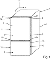
- a household refrigerator 1 in a schematic representation, which is designed for storing and preserving food.
- the household refrigerator 1 has a housing 2 in which at least one receiving space for food, for example a refrigerator compartment or a freezer compartment, is formed.
- a first receiving space is formed in the housing 2, which can be a cooling compartment and which can be closed at the front by a first door 3.
- the first door 3 is arranged pivotably on the housing 2.
- a second receiving space that is separate from the first receiving space and is a freezer compartment can be closed by a second door 4 that is separate from the first door 3.
- the second door 4 is also pivotably arranged on the housing 2.
- the two doors 3 and 4 are designed on the front and represent in particular front parts or also visible parts of the household refrigerator 1. They are in particular in the closed state, as shown in FIG Fig. 1 is shown, arranged in a vertical plane to one another.
- the first door 3 has a door leaf 5, which is a plate-like part and represents a base part or a base body of the door 3.
- the door leaf 5 has a first longitudinal side 6, which is a vertical longitudinal side, and has an opposite, second longitudinal side 7.
- a first channel trough 8 is formed on the first longitudinal side 6 and, in particular, a second channel trough 9 is formed on the second longitudinal side 7.
- the second door 4 is preferably designed accordingly and has a channel trough 11 on a first longitudinal side 10 and a channel trough 13 on an opposite, second longitudinal side 12.
- the channel troughs 11 and 13 are designed to be open laterally (in the width direction (x direction)).
- the channel troughs 8 and 9 can extend in the height direction (y-direction) of the door 3 and also of the household refrigerator 1 over the entire height of the door 3. The same can also be provided for the door 4.
- a partial area of the household refrigerator 1 is shown in a perspective view.
- the door 3 with the door leaf 5 is shown here.
- a first assembly area 14 is formed in the first channel trough 8.
- the first assembly area 14 is designed in such a way that it is designed to assemble a bearing part 15, which represents a separate component, or a separate functional part 16 different therefrom, according to claims 1 and 15, without re-assembly.
- the bearing part 15 is for receiving a door hinge 17, which in Fig. 2 is also drawn, formed. In the assembled state, the door hinge 17 engages with a bearing pin 18 in a receptacle 19 of the bearing part 15.
- the L-shaped door hinge 17 is fastened to the housing 2 with a mounting plate 20, in particular screwed on.
- the functional part 16 is, for example, a cover for an electronic module of a display unit and, according to the present invention, is part of an electronic display unit.
- the functional component is designed in particular as an elongated strip or as a bar.
- the door leaf 5 also has a second assembly area 21 on the opposite longitudinal side 7 in the second channel trough 9 there.
- the second assembly area 21 is also designed for optional assembly, without the assembly area 21 having to be rebuilt, of the bearing part or, optionally, of a different functional part according to claims 1 and 15.
- the bearing part 15 or, optionally, the functional part 16 according to claims 1 and 15 can also be installed here in the second assembly area 21.
- the articulated arm or the door hinge 17 can also be mounted on the right-hand side, as is indicated by the corresponding exemplary screw holes 22.
- the first assembly area 14 and the second assembly area 21 are designed mirror-symmetrically to a central axis A in an advantageous embodiment.
- the center axis A is directed in the height direction (y direction) of the door 5.
- the two assembly areas 14 and 21 are formed completely within the channel troughs 8 and 9, which are open laterally in the width direction (x-direction), and are thus sunk and designed to lie completely therein.
- the assembly areas 14 and 21 are formed in the upper area of the channel troughs 8 and 9, viewed in the vertical direction.
- the channel troughs 8 and 9 are, as shown in Fig. 2 to can be seen, in the vertical direction upwards and thus preferably open towards the upper edge of the door leaf 5.
- the assembly areas 14 and 21 are designed such that the bearing part 15 in the assembled state, viewed in the width direction of the door leaf 5, is arranged completely within a channel trough 8 or 9. The same is provided if a functional part 16 according to claims 1 and 15 is installed in an assembly area 14, 21.
- the bearing part 15 is installed in the channel trough 8 on the left.
- the functional part 16 according to claims 1 and 15 is installed on the opposite longitudinal side 9 in the second channel trough 9 there in the second assembly area 21.
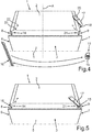
- Fig. 4 is in a corresponding perspective illustration as in Fig. 2 a variant of the door 3 and thus also a variant of the household refrigerator 1 is shown.
- the door 3 when viewed from the front of the household refrigerator 1, is a door hinged on the right.
- the bearing part 15 used as an identical component is provided here in the second assembly area 21 for installation.
- Fig. 4 the exploded view of the respective separate components is shown in this regard.
- Fig. 5 the assembled state of these components is shown.
- the bearing part 15 is for the FIGS. 2 to 5 explained variants provided as an identical component.
- the functional part 16 according to claims 1 and 15 for the to FIGS. 2 to 5 explained variants provided as an identical component. The same can be provided for the component 17.
- FIG. 1 In a further preferred embodiment, further assembly areas 23 and 24 are formed. These further assembly areas 23 and 24 are also designed for each optional attachment of a bearing part 15 or a functional part 16.
- the here third assembly area 23 is formed here in the first channel trough 8.
- the first assembly area 14 is formed in an upper end of the first channel trough 8.
- the third assembly area 23 is formed in a lower end of the first channel trough 8.
- the fourth assembly area 24 is here preferably formed in a lower end of the second channel trough 9.
- the second assembly area 21 is formed here in an upper end of the second channel trough 9.
- a bearing part 15 can be installed, for example, in the first assembly area 14 in a non-destructive detachable manner.
- the same bearing part 15 can, however, also be installed on the fourth assembly area 24 in order to enable an installation variant of the door 3.
- This enables the door 3 to be installed on the housing 2 as a door 3 hinged on the left or as a door 3 hinged on the right.
- a bearing part 15 can be installed as an identical component both in the second assembly area 21 and in the third assembly area 23.
- the assembly areas 14, 21, 23, 24 formed here in particular in the area of the corners of the square door 3, viewed at least crosswise, are designed for compatible accommodation of a common component in the form of a bearing part 15 or a functional part 16 according to claims 1 and 15 .
- channel troughs 8 and 9 are here preferably formed continuously from the upper end to the lower end, an assembly area 14, 21, 23, 24 can also extend over this entire height.
- a functional part 16 according to claims 1 and 15 can also extend over the entire height of a channel trough 8, 9, for example.
- a channel trough 8, 9 can also be designed, at least in some areas, as a gripping trough for engaging with fingers.
Description
Die Erfindung gemäß dem unabhängigen Anspruch 1 betrifft eine Tür für ein Haushaltskältegerät mit einem Türblatt, das an einer ersten vertikalen Längsseite eine in Breitenrichtung des Türblatts seitlich offene erste Rinnenmulde und an einer der ersten vertikalen Längsseite gegenüberliegenden zweiten vertikalen Längsseite eine in Breitenrichtung des Türblatts seitlich offene zweite Rinnenmulde aufweist. Des Weiteren betrifft die Erfindung auch ein Haushaltskältegerät mit einer derartigen Tür, sowie ein Verfahren zum Herstellen einer Tür gemäß dem unabhängigen Anspruch 15.The invention according to
Aus der
Zur Erhöhung der Variabilität von Haushaltsgerätetypen sind gegenwärtig vielfältigste unterschiedliche Bauteile erforderlich. Die Anzahl von Gleichbauteilen, die bei derartigen Gerätevarianten genutzt werden können, ist beschränkt. Derartiges ist auch bei der aus dem Stand der Technik bekannten Tür der Fall.A wide variety of different components are currently required to increase the variability of household appliance types. The number of identical components that can be used with such device variants is limited. This is also the case with the door known from the prior art.
Aus der
Darüber hinaus ist aus der
Es ist Aufgabe der vorliegenden Erfindung, eine Tür für ein Haushaltskältegerät zu schaffen, welche im Hinblick auf die variablere Verwendung für unterschiedliche Haushaltskältegerätevarianten verbessert ist. Entsprechend ist es auch Aufgabe, ein Haushaltskältegerät mit einer derartigen Tür, als auch ein Verfahren zum Herstellen einer Tür zu schaffen.It is the object of the present invention to create a door for a household refrigeration appliance which is improved with regard to the more variable use for different household refrigeration appliance variants. Accordingly, it is also an object to create a domestic refrigeration appliance with a door of this type, as well as a method for producing a door.
Die vorliegende Erfindung ist in den unabhängigen Ansprüchen 1 und 15 offenbart. Weitere Ausführungsbeispiele sind in den abhängigen Ansprüchen offenbart.The present invention is disclosed in
Ein Aspekt der Erfindung betrifft eine Tür für ein Haushaltskältegerät. Die Tür weist ein Türblatt auf, das an einer ersten vertikalen Längsseite eine in Breitenrichtung desOne aspect of the invention relates to a door for a household refrigerator. The door has a door leaf which, on a first vertical longitudinal side, is one in the width direction of the
Türblatts seitlich offene erste Rinnenmulde aufweist. An einer der ersten vertikalen Längsseite gegenüberliegenden zweiten vertikalen Längsseite weist das Türblatt eine in Breitenrichtung des Türblatts seitlich offene zweite Rinnenmulde auf. Das Türblatt ist ein plattenartiges Bauteil der Tür und stellt somit quasi den Korpus beziehungsweise den Grundkörper der Tür dar.Has the door leaf laterally open first channel trough. On a second vertical longitudinal side opposite the first vertical longitudinal side, the door leaf has a second channel trough open laterally in the width direction of the door leaf. The door leaf is a plate-like component of the door and thus represents the body or the basic body of the door.
Die erste Rinnenmulde weist einen ersten Montagebereich auf, an dem wahlweise ein Lagerteil für ein Türgelenk oder ein dazu unterschiedliches Funktionsteil montierbar ist. Die zweite Rinnenmulde weist einen zweiten Montagebereich auf, an dem wahlweise ein Lagerteil für ein Türgelenk oder ein dazu unterschiedliches Funktionsteil montierbar ist, wobei in dem ersten Montagebereich ein Lagerteil für ein Türgelenk montiert ist und in dem zweiten Montagebereich ein zu dem Lagerteil unterschiedliches Funktionsteil montiert ist, wobei dass das Funktionsteil ein Bauteil einer elektronischen Anzeigeeinheit ist.The first channel trough has a first assembly area on which a bearing part for a door hinge or a functional part different therefrom can optionally be mounted. The second trough has a second assembly area, on which a bearing part for a door hinge or a different functional part can optionally be mounted, a bearing part for a door hinge being mounted in the first assembly area and a functional part different from the bearing part being mounted in the second assembly area wherein the functional part is a component of an electronic display unit.
Die Montagebereiche sind in dem Zusammenhang derart ausgebildet, dass sie ohne Umbau es ermöglichen, sowohl ein Lagerteil für ein Türgelenk als auch ein dazu unterschiedliches Funktionsteil gemäß den Ansprüchen 1 und 15 wahlweise montieren zu können. Es ist daher kein Umbau des Montagebereichs erforderlich, wenn anstatt des Lagerteils ein Funktionsteil gemäß den Ansprüchen 1 und 15 montiert werden soll oder anstelle eines solchen Funktionsteils das Lagerteil montiert werden soll. Durch eine derartige Ausgestaltung ist nicht nur die Verwendung von Gleichbauteilen am Türblatt selbst erhöht, sondern auch dann der jeweilige Montageaufwand für die individuell an dem Türblatt, insbesondere in einem Montagebereich, anbringbare Zusatzkomponente minimiert.In this context, the assembly areas are designed in such a way that they make it possible to optionally assemble both a bearing part for a door hinge and a different functional part according to
Ein Montagebereich ist daher auch dadurch charakterisiert, dass er Mittel aufweist, die eine Montage eines Lagerteils oder eines Funktionsbauteils gemäß den Ansprüchen 1 und 15 ermöglicht. Das können beispielsweise Schraublöcher, Stecköffnungen, Haken, Bügel, etc. sein. Auch andere Mittel können vorgesehen sein.An assembly area is therefore also characterized in that it has means which enable a bearing part or a functional component to be assembled according to
Indem örtlich gerade auch an gegenüberliegenden Längsseiten des Türblatts redundant entsprechende Montagebereiche ausgebildet sind, kann die Tür auch im Hinblick auf ihren Verbau als an der einen Längsseite angeschlagene Tür oder auch an der anderen gegenüberliegenden Längsseite angeschlagene Tür genutzt werden. Sie kann somit an individuellen Seiten eines Gehäuses eines Haushaltskältegeräts verbaut werden, sodass hier dann eine linksseitig angeschlagene oder eine rechtsseitig angeschlagene Tür realisiert werden kann.Since corresponding assembly areas are locally redundantly formed on opposite longitudinal sides of the door leaf, the door can also be used with regard to its shoring as a door hinged on one long side or also on the other opposite longitudinal side. It can thus be installed on individual sides of a housing of a household refrigerator, so that a door hinged on the left or right-hand side can be realized here.
Vorzugsweise ist vorgesehen, dass die Montagebereiche auf gleicher Höhenlage in Höhenrichtung der Tür betrachtet in den Rinnenmulden ausgebildet sind. Auch dadurch kann der einfache und schnelle Verbau von den oben genannten Zusatzteilen, nämlich eines Lagerteils für ein Türgelenk oder eines dazu unterschiedlichen Funktionsteils gemäß den Ansprüchen 1 und 15 erfolgen und bei beiden Varianten können die jeweiligen Teile dann an gleichen Höhenlagen verbaut sein.It is preferably provided that the assembly areas are formed in the channel troughs at the same height as viewed in the height direction of the door. This also enables the simple and quick installation of the above-mentioned additional parts, namely a bearing part for a door hinge or a different functional part according to
Der Montagebereich kann sich nur bereichsweise über die gesamte Höhe der Tür erstrecken oder aber auch über die gesamte Höhe der Tür erstrecken.The assembly area can only extend partially over the entire height of the door or also over the entire height of the door.
In besonders vorteilhafter Weise ist vorgesehen, dass die Montagebereiche spiegelsymmetrisch zu einer Mittenachse, die in Höhenrichtung der Tür gewichtet ist, des Türblatts ausgebildet sind. Durch eine derartige individuelle Gleichheit der Montagebereiche kann der schnelle und einfache Verbau von diesen Zusatzteilen besonders vorteilhaft erfolgen. Die jeweilige an den gegenüberliegenden Längsseiten dann individuelle Orientierung der daran angeordneten Zusatzteile ist dann automatisch bereits richtig eingestellt. Besonders vorteilhaft ist diese spiegelsymmetrische Ausgestaltung der Montagebereiche dahingehend, dass die Zusatzteile sowohl in Tiefenrichtung der Tür als auch in Höhenrichtung jeweils gleich positioniert sind, sodass beispielsweise bei der Montage eines Lagerteils dann sowohl bei der links angeschlagenen Tür als auch bei der rechts angeschlagenen Tür die jeweils richtige Lage der Tür in Tiefenrichtung und in Höhenrichtung des Haushaltskältegeräts betrachtet zum Gehäuse des Haushaltskältegeräts erreicht ist. Daraus resultiert dann folglich auch die jeweilig gleiche Bewegungsart als auch die gleiche Bewegungslänge, beispielsweise beim Öffnen der Tür. Zuletzt ist durch diese Ausgestaltung dann auch ein Funktionsbauteil gemäß den Ansprüchen 1 und 15, welches für sich betrachtet ebenfalls ein Gleichbauteil sein kann, sowohl im ersten als auch im zweiten Montagebereich praktisch an gleicher Position, sodass auch hier sowohl beim linksseitigen als auch beim rechtsseitigen Verbau ein praktisch identisches und intuitives Konzept für einen Nutzer realisiert ist. Er findet somit quasi das Funktionsteil in Höhenrichtung und in Tiefenrichtung an der gleichen Position in den jeweiligen Montagebereichen, sodass beispielsweise ein Einsehen und/oder Bedienen eines derartigen Funktionsteils durch die praktisch gleichen Handlungsweisen und Bewegungsabläufe eines Nutzers erfolgen kann. Der diesbezüglich einzige Unterschied ist dann dahingehend, dass an unterschiedlichen Längsseiten dieses Funktionsteil vorhanden ist.In a particularly advantageous manner, it is provided that the assembly areas are designed mirror-symmetrically to a center axis of the door leaf, which is weighted in the height direction of the door. Such individual equality of the assembly areas enables these additional parts to be installed quickly and easily in a particularly advantageous manner. The respective individual orientation of the additional parts arranged thereon on the opposite long sides is then automatically set correctly. This mirror-symmetrical design of the assembly areas is particularly advantageous in that the additional parts are positioned identically both in the depth direction of the door and in the height direction, so that, for example, when assembling a bearing part, both the left-hinged door and the right-hinged door correct location the door is reached in the depth direction and in the height direction of the household refrigerator to the housing of the household refrigerator. This then results in the same type of movement and the same length of movement, for example when opening the door. Finally, through this configuration, a functional component according to
Es ist vorgesehen, dass das Funktionsbauteil ein Bauteil einer elektronischen Anzeigeeinheit ist. Vorzugsweise ist vorgesehen, dass das Funktionsteil eine elektronische Anzeigeeinheit ist. Dadurch kann in dieser Rinnenmulde selbst eine entsprechende Positionierung erfolgen, sodass diese einerseits geschützt und platzsparend angeordnet ist, andererseits jedoch dennoch durch die seitlich offene Ausgestaltung der Rinnenmulde ausreichend eingesehen werden kann.It is provided that the functional component is a component of an electronic display unit. It is preferably provided that the functional part is an electronic display unit. As a result, a corresponding positioning can take place in this channel trough itself, so that it is on the one hand protected and arranged in a space-saving manner, but on the other hand can still be seen sufficiently through the laterally open design of the channel trough.
In einer vorteilhaften Ausführung ist vorgesehen, dass das Funktionsteil im montierten Zustand vollständig innerhalb einer Rinnenmulde angeordnet ist. Dadurch sind die oben genannten Vorteile im besonderen Maße erreicht.In an advantageous embodiment it is provided that the functional part in the assembled state is arranged completely within a channel trough. As a result, the advantages mentioned above are achieved to a particular extent.
Es kann jedoch auch vorgesehen sein, dass sich das Funktionsbauteil im monierten Zustand bereichsweise aus der Rinnenmulde heraus erstreckt. Beispielsweise kann dies bei einem zusätzlichen aufgesetzten Griff der Fall sein.However, provision can also be made for the functional component to extend in regions out of the channel trough in the assembled state. For example, this can be the case with an additional attached handle.
Vorzugsweise ist vorgesehen, dass das Lagerteil im montierten Zustand vollständig innerhalb einer Rinnenmulde angeordnet ist. Auch dadurch ist ein geschützter und platzsparender Verbau ermöglicht.It is preferably provided that the bearing part in the assembled state is arranged completely within a channel trough. This also enables a protected and space-saving installation.
Vorzugsweise ist vorgesehen, dass die Montagebereiche so ausgebildet sind, dass ein und dasselbe Funktionsbauteil in dem ersten Montagebereich oder dem zweitenIt is preferably provided that the assembly areas are designed in such a way that one and the same functional component is in the first assembly area or the second
Montagebereich montierbar ist. Durch diese Ausgestaltung wird die Anzahl der Gleichbauteile zur Variantenbildung der Tür nochmals erhöht. Die Bereitstellung von unterschiedlichen Varianten von Komponenten der Tür ist dadurch deutlich reduziert. Dadurch ist sowohl Entwicklungsaufwand als auch die Lagerkapazität für diese Komponenten reduziert.Mounting area is mountable. With this configuration, the number of identical components for creating variants of the door is increased again. The provision of different variants of components of the door is thereby significantly reduced. This reduces both the development effort and the storage capacity for these components.
Vorzugsweise ist vorgesehen, dass die Montagebereiche so ausgebildet sind, dass ein und dasselbe Lagerteil in dem ersten Montagebereich oder dem zweiten Montagebereich montierbar ist. Auch diesbezüglich gelten die oben für das Funktionsbauteil genannten Vorteile.It is preferably provided that the assembly areas are designed such that one and the same bearing part can be mounted in the first assembly area or the second assembly area. The advantages mentioned above for the functional component also apply in this regard.
Vorzugsweise weist die erste Rinnenmulde einen dritten Montagebereich auf, an dem wahlweise ein Lagerteil für ein Türgelenk oder ein dazu unterschiedliches Funktionsteil montierbar ist, und die zweite Rinnenmulde weist einen vierten Montagebereich auf, an dem wahlweise ein Lagerteil für ein Türgelenk oder ein dazu unterschiedliches Funktionsteil montierbar ist. Dadurch ist die Möglichkeit der Variantenbildung einer Tür als auch deren Verbaupositionen an einem Gehäuse eines Haushaltskältegeräts erhöht. Insbesondere ist dadurch die Möglichkeit eines Anschlagwechsel der Tür einfach gegeben, und es kann die Anzahl der Gleichbauteile, nämlich ein Lagerteil oder ein Funktionsbauteil, die in den verschiedenen Montagebereichen verbaut werden können, erhöht werden.The first channel trough preferably has a third assembly area on which a bearing part for a door hinge or a different functional part can optionally be mounted, and the second channel trough has a fourth assembly area on which a bearing part for a door hinge or a different functional part can optionally be mounted is. This increases the possibility of creating variants of a door and also of its installation positions on a housing of a household refrigerator. In particular, this makes it easy to change the door stop, and the number of identical components, namely a bearing part or a functional component, which can be installed in the various assembly areas, can be increased.
Vorzugsweise ist der erste Montagbereich in der ersten Rinnenmulde gleich dem vierten Montagebereich in der zweiten Rinnenmulde ausgebildet, und ein und dasselbe Lagerteil ist wahlweise in dem ersten Montagebereich oder dem vierten Montagebereich montierbar ist. Zusätzlich oder anstatt dazu ist der zweite Montagbereich in der zweiten Rinnenmulde gleich dem dritten Montagebereich in der ersten Rinnenmulde ausgebildet, und ein und dasselbe Lagerteil ist wahlweise in dem zweiten Montagebereich oder dem dritten Montagebereich montierbar. Dadurch kann ein bezüglich der Positionen des Lagerteils an der Tür kreuzweiser Verbau vorgesehen werden, wodurch ein Anschlagwechsel der Tür besonders einfach ermöglicht ist.Preferably, the first assembly area in the first channel trough is designed like the fourth assembly area in the second channel trough, and one and the same bearing part can be optionally mounted in the first assembly area or the fourth assembly area. In addition to or instead of this, the second assembly area in the second channel trough is formed like the third assembly area in the first channel trough, and one and the same bearing part can optionally be mounted in the second assembly area or the third assembly area. As a result, a crosswise shoring with respect to the positions of the bearing part on the door can be provided, which enables the door to be changed in a particularly simple manner.
Insbesondere ist der erste Montagbereich in der ersten Rinnenmulde gleich dem vierten Montagebereich in der zweiten Rinnenmulde ausgebildet, und ein und dasselbe Funktionsbauteil ist wahlweise in dem ersten Montagebereich oder dem vierten Montagebereich montierbar. Zusätzlich oder anstatt dazu ist der zweite Montagbereich in der zweiten Rinnenmulde gleich dem dritten Montagebereich in der ersten Rinnenmulde ausgebildet, und ein und dasselbe Funktionsbauteil ist wahlweise in dem zweiten Montagebereich oder dem dritten Montagebereich montierbar. Dadurch kann ein bezüglich der Positionen des Lagerteils an der Tür kreuzweiser Verbau vorgesehen werden, wodurch ein Anschlagwechsel der Tür besonders einfach ermöglicht ist.In particular, the first assembly area in the first channel trough is formed like the fourth assembly area in the second channel trough, and one and the same Functional component can optionally be mounted in the first assembly area or the fourth assembly area. In addition to or instead of this, the second assembly area in the second channel trough is designed like the third assembly area in the first channel trough, and one and the same functional component can optionally be installed in the second assembly area or the third assembly area. As a result, a crosswise shoring with respect to the positions of the bearing part on the door can be provided, which enables the door to be changed in a particularly simple manner.
Vorzugsweise sind der erste Montagebereich, in Höhenrichtung der Tür betrachtet, an zumindest einem oberen Ende der ersten Rinnenmulde, der zweite Montagebereich zumindest an einem oberen Ende der zweiten Rinnenmulde, der dritte Montagebereich zumindest an einem unteren Ende der ersten Rinnenmulde und der vierte Montagebereich zumindest an einem unteren Ende der zweiten Rinnenmulde ausgebildet. Bei einer frontseitigen Betrachtung der Tür ergibt sich somit eine bevorzugte Ausführung, bei der an den vier Eckbereichen der Tür jeweils ein Montagebereich ausgebildet ist, von denen zumindest paarweise und/oder an spezifischen Positionen gleiche Montagebereiche gebildet sind. Dadurch ergeben sich vielfältige Bestückungsmöglichkeiten mit Lagerteilen und/oder Funktionsbauteilen, die dann auch als Gleichbauteile einfach, insbesondere abhängig von der zu erzeugenden Variante der Tür.The first assembly area, viewed in the vertical direction of the door, are preferably at at least one upper end of the first channel trough, the second assembly area at least at an upper end of the second channel trough, the third assembly area at least at a lower end of the first channel trough and the fourth assembly area at least a lower end of the second channel trough formed. When the door is viewed from the front, a preferred embodiment is thus obtained in which a mounting area is formed on each of the four corner areas of the door, of which mounting areas are formed at least in pairs and / or at specific positions. This results in a wide range of options for equipping with bearing parts and / or functional components, which are then also simple as identical components, in particular depending on the variant of the door to be produced.
Vorzugsweise ist ein Lagerteil oder ein Funktionsbauteil zerstörungsfrei lösbar an einem Montagebereich montierbar. Dadurch ist der reversible Austausch und der anderweitige Verbau dieser Komponenten an einem anderen Montagebereich einfach möglich.A bearing part or a functional component can preferably be mounted in a non-destructive detachable manner on an assembly area. As a result, these components can easily be exchanged reversibly and installed elsewhere in a different assembly area.
Vorzugsweise ist das Funktionsbauteil leistenförmig ausgebildet ist. Dadurch kann es auch in eine schmale Rinnenmulde eingebaut werden und eine relativ große Frontfläche bereitstellen, so dass entsprechend umfänglich Informationen darstellbar sind. Zusätzlich oder anstatt dazu kann zumindest eine Rinnenmulde zumindest bereichsweise als Griffmulde ausgebildet sein. Dadurch ist die Rinnenmulde multifunktionell ausgebildet und dennoch kompakt aufgebaut und an einer Schmalseite bzw. einer Randseite der Tür verbaubar.The functional component is preferably designed in the form of a strip. As a result, it can also be installed in a narrow channel trough and provide a relatively large front surface, so that information can be displayed in a correspondingly extensive manner. In addition to or instead of this, at least one channel recess can be designed as a grip recess, at least in some areas. As a result, the channel trough is designed to be multifunctional and yet compact and can be installed on a narrow side or an edge side of the door.
Es kann bei einer Ausführung auch vorgesehen sein, dass sich das Funktionsbauteil über zumindest 50%, insbesondere zumindest 60%, insbesondere zumindest 70%, insbesondere zumindest 80%, insbesondere zumindest 90%, insbesondere zumindest vollständig über die vertikale Länge einer Rinnenmulde erstreckt.In one embodiment, it can also be provided that the functional component extends over at least 50%, in particular at least 60%, in particular at least 70%, in particular at least 80%, in particular at least 90%, in particular at least completely over the vertical length of a channel trough.
Ein weiterer Aspekt der Erfindung betrifft ein Verfahren zum Herstellen einer Tür für ein Haushaltskältegerät, mit einem Türblatt, an dem an einer ersten vertikalen Längsseite eine in Breitenrichtung des Türblatts seitlich offene erste Rinnenmulde ausgebildet wird, und an einer der ersten vertikalen Längsseite gegenüberliegenden zweiten vertikalen Längsseite eine in Breitenrichtung des Türblatts seitlich offene zweite Rinnenmulde ausgebildet wird, wobei die erste Rinnenmulde mit einen ersten Montagebereich ausgebildet wird, an dem wahlweise ein Lagerteil für ein Türgelenk oder ein dazu unterschiedliches Funktionsteil montiert wird, und die zweite Rinnenmulde mit einem zweiten Montagebereich ausgebildet wird, an dem wahlweise ein Lagerteil für ein Türgelenk oder ein dazu unterschiedliches Funktionsteil montiert wird, wobei das Funktionsteil, das an dem ersten Montagebereich oder an dem zweiten Montagebereich montierbar ist, ein Bauteil einer elektronischen Anzeigeeinheit ist.Another aspect of the invention relates to a method for producing a door for a household refrigerator, with a door leaf on which a first channel trough open laterally in the width direction of the door leaf is formed on a first vertical longitudinal side, and on a second vertical longitudinal side opposite the first vertical longitudinal side a second gutter trough is formed laterally in the width direction of the door leaf, the first gutter trough being formed with a first assembly area on which either a bearing part for a door hinge or a different functional part is mounted, and the second gutter trough is formed with a second assembly area, on which either a bearing part for a door hinge or a different functional part is mounted, the functional part that can be mounted on the first assembly area or the second assembly area being a component of an electronic display unit.
Es kann vorzugsweise vorgesehen sein, dass ein und dasselbe Lagerteil an dem ersten Montagebereich oder dem zweiten Montagebereich montiert wird. Das Lagerteil als Gleichbauteil kann somit an zwei, zum Verbau des Lagerteils kompatibel ausgebildeten Montagebereichen montiert werden. Ein Umbau der Tür und somit eine Variantenbildung ist dadurch einfach möglich. Sowohl die Bestückung der Tür mit spezifischen Komponenten, als auch der Verbauort dieser spezifischen Komponenten ist dadurch flexibel möglich. Dadurch wird eine Tür ermöglicht, die an einer ersten Seite an einer Anschlagseite eines Gehäuses des Haushaltskältegeräts angeschlagen werden kann oder an einer zweiten Anschlagseite des Gehäuses angeschlagen verbaut werden kann.It can preferably be provided that one and the same bearing part is mounted on the first assembly area or the second assembly area. The bearing part as an identical component can thus be mounted in two assembly areas that are designed to be compatible with the installation of the bearing part. This makes it easy to convert the door and thus create a variant. Both the equipping of the door with specific components and the installation location of these specific components are therefore flexible. This enables a door that can be hinged on a first side on a stop side of a housing of the domestic refrigerator or can be installed hinged on a second stop side of the housing.
Es wird die erste Rinnenmulde vorzugsweise mit einem dritten Montagebereich ausgebildet, an dem wahlweise ein Lagerteil für ein Türgelenk oder ein dazu unterschiedliches Funktionsteil montiert wird, und es wird die zweite Rinnenmulde vorzugsweise mit einem vierten Montagebereich ausgebildet, an dem wahlweise ein Lagerteil für ein Türgelenk oder ein dazu unterschiedliches Funktionsteil montiert wird. Somit kann der einfache Umbau der Tür ermöglicht werden.The first channel trough is preferably designed with a third assembly area on which either a bearing part for a door hinge or a different functional part is mounted, and the second channel trough is preferably designed with a fourth assembly area on which a bearing part for a door hinge or a different functional part is mounted. This enables the door to be easily converted.
Es kann in einem Ausführungsbeispiel der erste Montagbereich in der ersten Rinnenmulde gleich dem vierten Montagebereich in der zweiten Rinnenmulde ausgebildet werden, und ein und dasselbe Lagerteil wird dann wahlweise in dem ersten Montagebereich oder dem vierten Montagebereich montiert. Es kann auch vorgesehen werden, dass der zweite Montagbereich in der zweiten Rinnenmulde gleich dem dritten Montagebereich in der ersten Rinnenmulde ausgebildet wird, und ein und dasselbe Lagerteil wird wahlweise in dem zweiten Montagebereich oder dem dritten Montagebereich montiert. Es können dadurch auch einfach Umbauten der Tür erzeugt werden, um diese unterschiedlich angeschlagen an einem Gehäuse anzubringen.In one embodiment, the first assembly area in the first channel trough can be formed like the fourth assembly area in the second channel trough, and one and the same bearing part is then optionally installed in the first assembly area or the fourth assembly area. It can also be provided that the second assembly area in the second channel trough is formed like the third assembly area in the first channel trough, and one and the same bearing part is optionally installed in the second assembly area or the third assembly area. In this way, the door can also be easily modified in order to attach it to a housing with different hinges.
Vorzugsweise wird der erste Montagbereich in der ersten Rinnenmulde gleich dem vierten Montagebereich in der zweiten Rinnenmulde ausgebildet, und ein und dasselbe Funktionsbauteil gemäß den Ansprüchen 1 und 15 wird wahlweise in dem ersten Montagebereich oder dem vierten Montagebereich montiert. Es ist zusätzlich oder anstatt dazu auch möglich, dass der zweite Montagbereich in der zweiten Rinnenmulde gleich dem dritten Montagebereich in der ersten Rinnenmulde ausgebildet wird, und ein und dasselbe Funktionsbauteil gemäß den Ansprüchen 1 und 15 wird wahlweise in dem zweiten Montagebereich oder dem dritten Montagebereich montiert. Auch dadurch ist die Möglichkeit der Variantenbildung der Tür einfach und schnell möglich. Insbesondere ergeben sich auch unterschiedliche Bestückungsmöglichkeiten der Tür mit einer maximalen Anzahl an Gleichbauteilen.The first assembly area in the first channel trough is preferably formed like the fourth assembly area in the second channel trough, and one and the same functional component according to
Vorzugsweise wird der erste Montagebereich, in Höhenrichtung der Tür betrachtet, an einem oberen Ende der ersten Rinnenmulde, der zweite Montagebereich an einem oberen Ende der zweiten Rinnenmulde, der dritte Montagebereich an einem unteren Ende der ersten Rinnenmulde und der vierte Montagebereich an einem unteren Ende der zweiten Rinnenmulde ausgebildet. Diese ganz spezifische Ausgestaltung der Tür ermöglicht im besonderen Maße einen einfachen und schnellen Umbau bzw. eine einfache Variantenherstellung der Tür für unterschiedliche Anschläge bzw. dem Anschlagen an unterschiedlichen Vertikalseiten an dem Gehäuse.The first assembly area, viewed in the vertical direction of the door, is preferably at an upper end of the first channel trough, the second assembly area at an upper end of the second channel trough, the third assembly area at a lower end of the first channel trough and the fourth assembly area at a lower end of the second channel trough formed. This very specific design of the door enables, to a particular degree, a simple and quick conversion or a simple production of variants of the door for different stops or for stopping on different vertical sides of the housing.
Ein weiterer Aspekt der Erfindung betrifft ein Haushaltskältegerät mit einer Tür gemäß dem oben genannten Aspekt oder einer vorteilhaften Ausgestaltung davon.Another aspect of the invention relates to a household refrigerator with a door according to the above aspect or an advantageous embodiment thereof.
Mit Angaben "oben", "unten", "vorne", "hinten, "horizontal", "vertikal", "Tiefenrichtung", "Breitenrichtung", "Höhenrichtung" etc. sind die bei einem bestimmungsgemäßen Gebrauch und bestimmungsgemäßem Anordnen der Tür bzw. des Geräts gegebenen Positionen und Orientierungen angegeben.With information "above", "below", "front", "rear", "horizontal", "vertical", "depth direction", "width direction", "height direction" etc. are the with a proper use and proper arrangement of the door or . positions and orientations given for the device.
Weitere Merkmale der Erfindung ergeben sich aus den Ansprüchen, den Figuren und der Figurenbeschreibung.Further features of the invention emerge from the claims, the figures and the description of the figures.
Ausführungsbeispiele der Erfindung werden nachfolgend anhand schematischer Zeichnungen näher erläutert. Es zeigen:
- Fig. 1
- eine perspektivische Darstellung eines Ausführungsbeispiels eines erfindungsgemäßen Haushaltskältegeräts;
- Fig. 2
- eine perspektivische Darstellung eines Teilbereichs des Haushaltskältegeräts gemäß
Fig. 1 ; - Fig. 3
- eine Darstellung der Ausgestaltung gemäß
Fig. 2 mit den zusammengebauten Komponenten; - Fig. 4
- eine perspektivische Teildarstellung des Haushaltskältegeräts gemäß
Fig. 1 in einer Variante zuFig. 2 und Fig. 3 mit den diesbezüglich verwendeten Komponenten in einer Explosionsdarstellung; und - Fig. 5
- die Darstellung gemäß
Fig. 4 im zusammengebauten Zustand der Komponenten.
- Fig. 1
- a perspective view of an embodiment of a household refrigerator according to the invention;
- Fig. 2
- a perspective view of a portion of the household refrigerator according to
Fig. 1 ; - Fig. 3
- a representation of the design according to
Fig. 2 with the assembled components; - Fig. 4
- a perspective partial representation of the household refrigerator according to
Fig. 1 in a variant tooFIGS. 2 and 3 with the related components used in an exploded view; and - Fig. 5
- the representation according to
Fig. 4 in the assembled state of the components.
In den Figuren werden gleiche oder funktionsgleiche Elementen mit den gleichen Bezugszeichen versehen.Identical or functionally identical elements are provided with the same reference symbols in the figures.
In
Die erste Tür 3 weist ein Türblatt 5 auf, welches ein plattenartiges Teil ist und ein Basisteil beziehungsweise ein Grundkörper der Tür 3 darstellt. Das Türblatt 5 weist eine erste Längsseite 6, die eine vertikale Längsseite ist, und weist eine gegenüberliegende zweite Längsseite 7 auf. Wie zu erkennen ist, ist an der ersten Längsseite 6 eine erste Rinnenmulde 8 und an der zweiten Längsseite 7 insbesondere eine zweite Rinnenmulde 9 ausgebildet. Vorzugsweise ist die zweite Tür 4 entsprechend ausgebildet und weist an einer ersten Längsseite 10 eine Rinnenmulde 11 und an einer gegenüberliegenden zweiten Längsseite 12 eine Rinnenmulde 13 auf. Die Rinnenmulden 11 und 13 sind seitlich (in Breitenrichtung (x-Richtung)) offen ausgebildet.The
Die Rinnenmulden 8 und 9 können sich in Höhenrichtung (y-Richtung) der Tür 3 und auch des Haushaltskältegeräts 1 über die gesamte Höhe der Tür 3 erstrecken. Entsprechendes kann auch bei der Tür 4 vorgesehen sein.The
In
Im gezeigten Ausführungsbeispiel ist das Funktionsteil 16 beispielsweise eine Abdeckung für ein Elektronikmodul einer Anzeigeeinheit und ist gemäß der vorliegenden Erfindung Bestandteil einer elektronischen Anzeigeeinheit. Das Funktionsbauteil ist insbesondere als länglicher Streifen bzw. als Leiste ausgebildet. Wie darüber hinaus in
Der erste Montagebereich 14 und der zweite Montagebereich 21 sind in vorteilhafter Ausführung spiegelsymmetrisch zu einer Mittenachse A ausgebildet. Die Mittenachse A ist in Höhenrichtung (y-Richtung) der Tür 5 gerichtet. Die beiden Montagebereiche 14 und 21 sind vollständig innerhalb der in Breitenrichtung (x-Richtung) jeweils seitlich offenen Rinnenmulden 8 und 9 ausgebildet und somit versenkt und vollständig darin liegend gestaltet.The
Die Montagebereiche 14 und 21 sind in Höhenrichtung betrachtet im oberen Bereich der Rinnenmulden 8 und 9 ausgebildet. Die Rinnenmulden 8 und 9 sind, wie dies in
Bei der hier gezeigten Ausführung ist vorgesehen, dass bei frontseitiger Betrachtung des Haushaltskältegeräts 1 eine linksseitig angeschlagene Tür 3 ausgebildet ist. Bei dieser Variante der Tür 3 und somit auch bei dieser Variante des Haushaltskältegeräts 1 ist das Lagerteil 15 in der linksseitigen Rinnenmulde 8 verbaut. Bei der hier gezeigten Ausgestaltung ist an der gegenüberliegenden Längsseite 9 in der dortigen zweiten Rinnenmulde 9 in dem zweiten Montagebereich 21 das Funktionsteil 16 gemäß den Ansprüchen 1 und 15 verbaut.In the embodiment shown here, it is provided that when the
In
In
In
In einem bevorzugten Ausführungsbeispiel ist es vorgesehen, dass ein Lagerteil 15 beispielsweise in dem ersten Montagebereich 14 zerstörungsfrei lösbar verbaut werden kann. Das gleiche Lagerteil 15 kann aber auch, um eine Verbauvariante der Tür 3 zu ermöglichen, an dem vierten Montagebereich 24 verbaut werden. Dadurch ist es ermöglicht, dass die Tür 3 als linksseitig angeschlagene Tür 3 oder als rechtsseitig angeschlagene Tür 3 an dem Gehäuse 2 verbaut werden kann. Entsprechend kann ein Lagerteil 15 als Gleichbauteil sowohl in dem zweiten Montagebereich 21 als auch in dem dritten Montagebereich 23 verbaut werden. Somit sind bei dem genannten Beispiel die hier insbesondere im Bereich der Ecken der viereckigen Tür 3 ausgebildeten Montagebereichen 14, 21, 23, 24 zumindest kreuzweise betrachtet zur kompatiblen Aufnahme eines Gleichbauteils in Form eines Lagerteils 15 oder eines Funktionsteils 16 gemäß den Ansprüchen 1 und 15 ausgebildet.In a preferred exemplary embodiment, it is provided that a bearing
Da die Rinnenmulden 8 und 9 hier vorzugsweise vom oberen Ende bis zum unteren Ende durchgehend ausgebildet sind, kann sich ein Montagebereich 14, 21, 23, 24 auch über diese gesamte Höhe erstrecken. Insbesondere kann sich auch ein Funktionsteil 16 gemäß den Ansprüchen 1 und 15 über die beispielsweise die gesamte Höhe einer Rinnenmulde 8, 9 erstrecken.Since the
Bei allen Ausführungsbeispielen kann eine Rinnenmulde 8, 9 auch zumindest bereichsweise als Griffmulde zum Eingreifen mit Fingern ausgebildet sein.In all of the exemplary embodiments, a
- 11
- HaushaltskältegerätHousehold refrigerator
- 22
- Gehäusecasing
- 33
- Türdoor
- 44th
- Türdoor
- 55
- TürblattDoor leaf
- 66th
- LängsseiteLong side
- 77th
- LängsseiteLong side
- 88th
- RinnenmuldeGutter trough
- 99
- RinnenmuldeGutter trough
- 1010
- LängsseiteLong side
- 1111
- RinnenmuldeGutter trough
- 1212th
- LängsseiteLong side
- 1313th
- RinnenmuldeGutter trough
- 1414th
- MontagebereichAssembly area
- 1515th
- LagerteilBearing part
- 1616
- FunktionsteilFunctional part
- 1717th
- TürgelenkDoor hinge
- 1818th
- LagerzapfenJournal
- 1919th
- Aufnahmerecording
- 2020th
- MontageplatteMounting plate
- 2121
- MontagebereichAssembly area
- 2222nd
- SchraublochScrew hole
- 2323
- MontagebereichAssembly area
- 2424
- MontagebereichAssembly area
- AA.
- MittenachseCentral axis
Claims (15)
- Door (3, 4) for a household refrigeration appliance (1), with a door leaf (5), which has a first groove recess (8) that is open to the side in the width direction (x) of the door leaf (5) on a first vertical longitudinal side (6) and a second groove recess (9) that is open to the side in the width direction (x) of the door leaf (5) on a second vertical longitudinal side (7) opposite the first vertical longitudinal side (6), wherein the first groove recess (8) has a first installation region (14), on which a mounting part (15) for a door joint or a functional part (16) different therefrom optionally can be installed, and the second groove recess (9) has a second installation region (21), on which a mounting part (15) for a door joint or a functional part (16) different therefrom optionally can be installed, wherein a mounting part (15) for a door joint is installed in the first installation region (14) and a functional part (16) different from the mounting part (15) is installed in the second installation region (21), characterised in that the functional part (16) is a component part of an electronic display unit.
- Door (3, 4) according to claim 1, characterised in that the installation regions (14, 21) are embodied at the same height position in the groove recesses (8, 9).
- Door (3, 4) according to claim 1 or 2, characterised in that the installation regions (14, 21) are embodied with mirror symmetry in relation to a centre axis (A), directed in the height direction (y) of the door (3, 4), of the door leaf (5).
- Door (3, 4) according to one of the preceding claims, characterised in that the functional part (16), in the installed state, is arranged entirely within a groove recess (8, 9).
- Door (3, 4) according to one of the preceding claims, characterised in that the mounting part (15), in the installed state, is arranged entirely within a groove recess (8, 9).
- Door (3, 4) according to one of the preceding claims, characterised in that the installation regions (14, 21) are embodied such that one and the same functional part (16) can be installed in the first installation region (14) or the second installation region (21).
- Door (3, 4) according to one of the preceding claims, characterised in that the first groove recess (8) has a third installation region (23), on which a mounting part (15) for a door joint or a functional part (16) different therefrom optionally can be installed, and the second groove recess (9) has a fourth installation region (24), on which a mounting part (15) for a door joint or a functional part (16) different therefrom optionally can be installed.
- Door (3, 4) according to claim 7, characterised in that the first installation region (14) in the first groove recess (8) is embodied identically to the fourth installation region (24) in the second groove recess (9), and one and the same mounting part (15) optionally can be installed in the first installation region (14) or the fourth installation region (24), and/or the second installation region (21) in the second groove recess (9) is embodied identically to the third installation region (23) in the first groove recess (8), and one and the same mounting part (15) optionally can be installed in the second installation region (21) or the third installation region (23).
- Door (3, 4) according to claim 7 or 8, characterised in that the first installation region (14) in the first groove recess (8) is embodied identically to the fourth installation region (24) in the second groove recess (9), and one and the same functional component part (16) optionally can be installed in the first installation region (14) or the fourth installation region (24), and/or the second installation region (21) in the second groove recess (9) is embodied identically to the third installation region (23) in the first groove recess (8), and one and the same functional component part (16) optionally can be installed in the second installation region (21) or the third installation region (23).
- Door (3, 4) according to one of the preceding claims 7 to 9, characterised in that the first installation region (14), viewed in the height direction (y) of the door (3, 4), is embodied at an upper end of the first groove recess (8), the second installation region (21) at an upper end of the second groove recess (9), the third installation region (23) at a lower end of the first groove recess (8) and the fourth installation region (24) at a lower end of the second groove recess (9).
- Door (3, 4) according to one of the preceding claims, characterised in that the installation regions (14, 21) are embodied such that one and the same mounting part (15) can be installed in one of the installation regions (14, 21, 23, 24) or in another of the installation regions (14, 21, 23, 24).
- Door (3, 4) according to one of the preceding claims, characterised in that a mounting part (15) or a functional component part (16) can be installed on an installation region (14, 21, 23, 24) such that it can be detached in a non-destructive manner.
- Door (3, 4) according to one of the preceding claims, characterised in that the functional component part (16) is embodied in a bar-like manner and/or at least one groove recess (8, 9) is embodied as a handle recess, at least in regions.
- Household refrigeration appliance (1) with a door (3, 4) according to one of the preceding claims.
- Method for producing a door (3, 4) according to claim 1 for a household refrigeration appliance (1), with a door leaf (5), on which a first groove recess (8) that is open to the side in the width direction (x) of the door leaf (5) is embodied on a first vertical longitudinal side (6), and a second groove recess (9) that is open to the side in the width direction (x) of the door leaf (5) is embodied on a second vertical longitudinal side (7) opposite the first vertical longitudinal side (6), wherein the first groove recess (8) is embodied with a first installation region (14), on which a mounting part (15) for a door joint or a functional part (16) different therefrom, which is a component part of an electronic display unit, is optionally installed, and the second groove recess (9) is embodied with a second installation region (21), on which a mounting part (15) for a door joint or a functional part (16) different therefrom, which is a component part of an electronic display unit, is optionally installed.
Applications Claiming Priority (1)
| Application Number | Priority Date | Filing Date | Title |
|---|---|---|---|
| DE102017217632.6A DE102017217632A1 (en) | 2017-10-04 | 2017-10-04 | Door for a household refrigeration appliance with the same mounting device in side channels of opposite longitudinal sides, as well as household refrigeration appliance and method for producing a door |
Publications (2)
| Publication Number | Publication Date |
|---|---|
| EP3467414A1 EP3467414A1 (en) | 2019-04-10 |
| EP3467414B1 true EP3467414B1 (en) | 2021-08-04 |
Family
ID=63311830
Family Applications (2)
| Application Number | Title | Priority Date | Filing Date |
|---|---|---|---|
| EP18189571.5A Active EP3467414B1 (en) | 2017-10-04 | 2018-08-17 | Door for a household refrigeration device with identical mounting device in lateral ducts of opposite lateral sides, and household refrigeration device and method for producing a door |
| EP18194703.7A Withdrawn EP3467416A1 (en) | 2017-10-04 | 2018-09-17 | Domestic appliance |
Family Applications After (1)
| Application Number | Title | Priority Date | Filing Date |
|---|---|---|---|
| EP18194703.7A Withdrawn EP3467416A1 (en) | 2017-10-04 | 2018-09-17 | Domestic appliance |
Country Status (2)
| Country | Link |
|---|---|
| EP (2) | EP3467414B1 (en) |
| DE (1) | DE102017217632A1 (en) |
Families Citing this family (4)
| Publication number | Priority date | Publication date | Assignee | Title |
|---|---|---|---|---|
| DE102019113461A1 (en) * | 2019-04-18 | 2020-10-22 | Liebherr-Hausgeräte Ochsenhausen GmbH | Fridge and / or freezer |
| DE102020109618A1 (en) | 2020-02-14 | 2021-08-19 | Liebherr-Hausgeräte Ochsenhausen GmbH | Fridge and / or freezer with control electronics next to the door |
| DE102020208158A1 (en) | 2020-06-30 | 2021-12-30 | BSH Hausgeräte GmbH | Household appliance with a closure element and a specifically shaped recessed grip on a narrow side of the closure element |
| DE102021208921A1 (en) | 2021-08-13 | 2023-02-16 | BSH Hausgeräte GmbH | Door that can be hinged on both sides with a specific installation area and optical display of the handle side, as well as a household refrigeration appliance |
Family Cites Families (14)
| Publication number | Priority date | Publication date | Assignee | Title |
|---|---|---|---|---|
| FR2527848A2 (en) * | 1982-05-28 | 1983-12-02 | Thomson Brandt | Door hinges for refrigerator with regulatable butter compartment temp. - have concentric cylindrical contacts in hinge units and can be used interchangeably for door fittings on either side opening |
| JPH04136491U (en) * | 1991-06-07 | 1992-12-18 | 振興 甘 | two-way refrigerator door |
| IT233950Y1 (en) * | 1994-07-20 | 2000-02-16 | Whirlpool Italia | HINGE ORGAN IN PARTICULAR FOR HOUSEHOLD APPLIANCES, APPLICABLE BOTH ON DOORS WITH RIGHT OPENING AND ON DOORS WITH |
| TR200202566A2 (en) * | 2002-11-22 | 2004-06-21 | Vestel Beyaz E�Ya Sanay� Ve T�Caret A.�. | Electronically controlled cooler with door opening direction changeable. |
| US20070204648A1 (en) * | 2006-03-03 | 2007-09-06 | Smale Jeffrey J | Step-down top hinge for refrigerator door with external dispenser |
| JP4828346B2 (en) * | 2006-08-01 | 2011-11-30 | 株式会社ニシムラ | Left and right pivot hinge |
| WO2010023818A1 (en) * | 2008-08-26 | 2010-03-04 | パナソニック株式会社 | Refrigerator |
| DE102008044132A1 (en) * | 2008-11-27 | 2010-06-02 | BSH Bosch und Siemens Hausgeräte GmbH | Refrigerating appliance with double-sided door |
| EP3763869A3 (en) * | 2009-01-23 | 2021-03-24 | LG Electronics Inc. | Laundry treating machine |
| DE102012200810A1 (en) * | 2012-01-20 | 2013-07-25 | BSH Bosch und Siemens Hausgeräte GmbH | Refrigeration appliance with user interface arranged in the door |
| DE102012200813A1 (en) * | 2012-01-20 | 2013-07-25 | BSH Bosch und Siemens Hausgeräte GmbH | Heat-insulating door for a refrigeration device |
| DE102015209258A1 (en) | 2015-05-20 | 2016-11-24 | BSH Hausgeräte GmbH | Domestic refrigerator with a pivot axis having door-side bearing part and a arranged outside the side handle recess pivot axis |
| JP6265950B2 (en) * | 2015-07-31 | 2018-01-24 | 三菱電機エンジニアリング株式会社 | Storage |
| KR101954874B1 (en) * | 2016-01-05 | 2019-05-30 | 엘지전자 주식회사 | Refirgerator |
-
2017
- 2017-10-04 DE DE102017217632.6A patent/DE102017217632A1/en not_active Withdrawn
-
2018
- 2018-08-17 EP EP18189571.5A patent/EP3467414B1/en active Active
- 2018-09-17 EP EP18194703.7A patent/EP3467416A1/en not_active Withdrawn
Also Published As
| Publication number | Publication date |
|---|---|
| EP3467414A1 (en) | 2019-04-10 |
| EP3467416A1 (en) | 2019-04-10 |
| DE102017217632A1 (en) | 2019-04-04 |
Similar Documents
| Publication | Publication Date | Title |
|---|---|---|
| EP3467414B1 (en) | Door for a household refrigeration device with identical mounting device in lateral ducts of opposite lateral sides, and household refrigeration device and method for producing a door | |
| EP2531065B1 (en) | Drawer structure | |
| EP2059145B1 (en) | Drawer | |
| EP1881775B1 (en) | Arrangement of telescopic extensions | |
| EP3371531B1 (en) | Door comprising a door frame and a recessed handle element, and a domestic refrigeration appliance comprising such a door | |
| EP1926953B1 (en) | Door for a household device | |
| EP1926949B1 (en) | Housing for a domestic appliance | |
| WO2005113923A1 (en) | Recessed grip | |
| DE3405343C2 (en) | ||
| DE102006039025A1 (en) | Guidance fitting for sliding door fitting, has u-side pieces forming fixing side piece and guiding side piece, and fixing bolt fixedly connected with sliding leaves, with which glider can be fixed at leaves in hanging condition of door | |
| EP2901085A1 (en) | Door for a domestic appliance and domestic appliance for preparing foods having a door | |
| EP1926952B1 (en) | Door for a refrigerator | |
| EP3189749A1 (en) | Pull-out guide for a movable furniture part | |
| EP1454026B1 (en) | Mounting plate for adjustably retaining furniture hinges on the body of pieces of furniture | |
| EP2281159B1 (en) | Door for a household appliance | |
| DE102019208449A1 (en) | Food receptacle with a partition held at different heights in different spatial directions, as well as a method for assembling a partition | |
| DE202018107035U1 (en) | Drawer connecting device for connecting a drawer front to a drawer side part | |
| EP2758718B1 (en) | Cooking device with a door | |
| EP3556977B1 (en) | Frame member for a furniture frame and furniture | |
| DE102020213908A1 (en) | Household appliance with a symmetrical bearing angle of a hinge for a door, and method | |
| DE60207672T2 (en) | Device for releasing a swing gate panel | |
| DE102022203496A1 (en) | Door for a household appliance with a rotating handle that opens onto the side of a door leaf, and household appliance | |
| DE60207673T2 (en) | Device for releasing a swing gate panel | |
| DE202018105626U1 (en) | Lid fitting for pivotably attaching a lid to a furniture body and furniture with such a lid fitting | |
| DE202019106034U1 (en) | Housing for receiving a heat-emitting electrical component |
Legal Events
| Date | Code | Title | Description |
|---|---|---|---|
| PUAI | Public reference made under article 153(3) epc to a published international application that has entered the european phase |
Free format text: ORIGINAL CODE: 0009012 |
|
| STAA | Information on the status of an ep patent application or granted ep patent |
Free format text: STATUS: THE APPLICATION HAS BEEN PUBLISHED |
|
| AK | Designated contracting states |
Kind code of ref document: A1 Designated state(s): AL AT BE BG CH CY CZ DE DK EE ES FI FR GB GR HR HU IE IS IT LI LT LU LV MC MK MT NL NO PL PT RO RS SE SI SK SM TR |
|
| AX | Request for extension of the european patent |
Extension state: BA ME |
|
| STAA | Information on the status of an ep patent application or granted ep patent |
Free format text: STATUS: REQUEST FOR EXAMINATION WAS MADE |
|
| 17P | Request for examination filed |
Effective date: 20191010 |
|
| RBV | Designated contracting states (corrected) |
Designated state(s): AL AT BE BG CH CY CZ DE DK EE ES FI FR GB GR HR HU IE IS IT LI LT LU LV MC MK MT NL NO PL PT RO RS SE SI SK SM TR |
|
| GRAP | Despatch of communication of intention to grant a patent |
Free format text: ORIGINAL CODE: EPIDOSNIGR1 |
|
| STAA | Information on the status of an ep patent application or granted ep patent |
Free format text: STATUS: GRANT OF PATENT IS INTENDED |
|
| INTG | Intention to grant announced |
Effective date: 20210312 |
|
| GRAS | Grant fee paid |
Free format text: ORIGINAL CODE: EPIDOSNIGR3 |
|
| GRAA | (expected) grant |
Free format text: ORIGINAL CODE: 0009210 |
|
| STAA | Information on the status of an ep patent application or granted ep patent |
Free format text: STATUS: THE PATENT HAS BEEN GRANTED |
|
| AK | Designated contracting states |
Kind code of ref document: B1 Designated state(s): AL AT BE BG CH CY CZ DE DK EE ES FI FR GB GR HR HU IE IS IT LI LT LU LV MC MK MT NL NO PL PT RO RS SE SI SK SM TR |
|
| REG | Reference to a national code |
Ref country code: GB Ref legal event code: FG4D Free format text: NOT ENGLISH |
|
| REG | Reference to a national code |
Ref country code: AT Ref legal event code: REF Ref document number: 1417372 Country of ref document: AT Kind code of ref document: T Effective date: 20210815 |
|
| REG | Reference to a national code |
Ref country code: CH Ref legal event code: EP |
|
| REG | Reference to a national code |
Ref country code: DE Ref legal event code: R096 Ref document number: 502018006404 Country of ref document: DE |
|
| REG | Reference to a national code |
Ref country code: IE Ref legal event code: FG4D Free format text: LANGUAGE OF EP DOCUMENT: GERMAN |
|
| REG | Reference to a national code |
Ref country code: LT Ref legal event code: MG9D |
|
| REG | Reference to a national code |
Ref country code: NL Ref legal event code: MP Effective date: 20210804 |
|
| PG25 | Lapsed in a contracting state [announced via postgrant information from national office to epo] |
Ref country code: HR Free format text: LAPSE BECAUSE OF FAILURE TO SUBMIT A TRANSLATION OF THE DESCRIPTION OR TO PAY THE FEE WITHIN THE PRESCRIBED TIME-LIMIT Effective date: 20210804 Ref country code: FI Free format text: LAPSE BECAUSE OF FAILURE TO SUBMIT A TRANSLATION OF THE DESCRIPTION OR TO PAY THE FEE WITHIN THE PRESCRIBED TIME-LIMIT Effective date: 20210804 Ref country code: ES Free format text: LAPSE BECAUSE OF FAILURE TO SUBMIT A TRANSLATION OF THE DESCRIPTION OR TO PAY THE FEE WITHIN THE PRESCRIBED TIME-LIMIT Effective date: 20210804 Ref country code: SE Free format text: LAPSE BECAUSE OF FAILURE TO SUBMIT A TRANSLATION OF THE DESCRIPTION OR TO PAY THE FEE WITHIN THE PRESCRIBED TIME-LIMIT Effective date: 20210804 Ref country code: RS Free format text: LAPSE BECAUSE OF FAILURE TO SUBMIT A TRANSLATION OF THE DESCRIPTION OR TO PAY THE FEE WITHIN THE PRESCRIBED TIME-LIMIT Effective date: 20210804 Ref country code: LT Free format text: LAPSE BECAUSE OF FAILURE TO SUBMIT A TRANSLATION OF THE DESCRIPTION OR TO PAY THE FEE WITHIN THE PRESCRIBED TIME-LIMIT Effective date: 20210804 Ref country code: BG Free format text: LAPSE BECAUSE OF FAILURE TO SUBMIT A TRANSLATION OF THE DESCRIPTION OR TO PAY THE FEE WITHIN THE PRESCRIBED TIME-LIMIT Effective date: 20211104 Ref country code: NO Free format text: LAPSE BECAUSE OF FAILURE TO SUBMIT A TRANSLATION OF THE DESCRIPTION OR TO PAY THE FEE WITHIN THE PRESCRIBED TIME-LIMIT Effective date: 20211104 Ref country code: PT Free format text: LAPSE BECAUSE OF FAILURE TO SUBMIT A TRANSLATION OF THE DESCRIPTION OR TO PAY THE FEE WITHIN THE PRESCRIBED TIME-LIMIT Effective date: 20211206 |
|
| PG25 | Lapsed in a contracting state [announced via postgrant information from national office to epo] |
Ref country code: PL Free format text: LAPSE BECAUSE OF FAILURE TO SUBMIT A TRANSLATION OF THE DESCRIPTION OR TO PAY THE FEE WITHIN THE PRESCRIBED TIME-LIMIT Effective date: 20210804 Ref country code: LV Free format text: LAPSE BECAUSE OF FAILURE TO SUBMIT A TRANSLATION OF THE DESCRIPTION OR TO PAY THE FEE WITHIN THE PRESCRIBED TIME-LIMIT Effective date: 20210804 Ref country code: GR Free format text: LAPSE BECAUSE OF FAILURE TO SUBMIT A TRANSLATION OF THE DESCRIPTION OR TO PAY THE FEE WITHIN THE PRESCRIBED TIME-LIMIT Effective date: 20211105 |
|
| REG | Reference to a national code |
Ref country code: CH Ref legal event code: PL |
|
| PG25 | Lapsed in a contracting state [announced via postgrant information from national office to epo] |
Ref country code: NL Free format text: LAPSE BECAUSE OF FAILURE TO SUBMIT A TRANSLATION OF THE DESCRIPTION OR TO PAY THE FEE WITHIN THE PRESCRIBED TIME-LIMIT Effective date: 20210804 |
|
| REG | Reference to a national code |
Ref country code: BE Ref legal event code: MM Effective date: 20210831 |
|
| PG25 | Lapsed in a contracting state [announced via postgrant information from national office to epo] |
Ref country code: LI Free format text: LAPSE BECAUSE OF NON-PAYMENT OF DUE FEES Effective date: 20210831 Ref country code: DK Free format text: LAPSE BECAUSE OF FAILURE TO SUBMIT A TRANSLATION OF THE DESCRIPTION OR TO PAY THE FEE WITHIN THE PRESCRIBED TIME-LIMIT Effective date: 20210804 Ref country code: CH Free format text: LAPSE BECAUSE OF NON-PAYMENT OF DUE FEES Effective date: 20210831 |
|
| REG | Reference to a national code |
Ref country code: DE Ref legal event code: R097 Ref document number: 502018006404 Country of ref document: DE |
|
| PG25 | Lapsed in a contracting state [announced via postgrant information from national office to epo] |
Ref country code: SM Free format text: LAPSE BECAUSE OF FAILURE TO SUBMIT A TRANSLATION OF THE DESCRIPTION OR TO PAY THE FEE WITHIN THE PRESCRIBED TIME-LIMIT Effective date: 20210804 Ref country code: SK Free format text: LAPSE BECAUSE OF FAILURE TO SUBMIT A TRANSLATION OF THE DESCRIPTION OR TO PAY THE FEE WITHIN THE PRESCRIBED TIME-LIMIT Effective date: 20210804 Ref country code: RO Free format text: LAPSE BECAUSE OF FAILURE TO SUBMIT A TRANSLATION OF THE DESCRIPTION OR TO PAY THE FEE WITHIN THE PRESCRIBED TIME-LIMIT Effective date: 20210804 Ref country code: MC Free format text: LAPSE BECAUSE OF FAILURE TO SUBMIT A TRANSLATION OF THE DESCRIPTION OR TO PAY THE FEE WITHIN THE PRESCRIBED TIME-LIMIT Effective date: 20210804 Ref country code: LU Free format text: LAPSE BECAUSE OF NON-PAYMENT OF DUE FEES Effective date: 20210817 Ref country code: EE Free format text: LAPSE BECAUSE OF FAILURE TO SUBMIT A TRANSLATION OF THE DESCRIPTION OR TO PAY THE FEE WITHIN THE PRESCRIBED TIME-LIMIT Effective date: 20210804 Ref country code: CZ Free format text: LAPSE BECAUSE OF FAILURE TO SUBMIT A TRANSLATION OF THE DESCRIPTION OR TO PAY THE FEE WITHIN THE PRESCRIBED TIME-LIMIT Effective date: 20210804 Ref country code: AL Free format text: LAPSE BECAUSE OF FAILURE TO SUBMIT A TRANSLATION OF THE DESCRIPTION OR TO PAY THE FEE WITHIN THE PRESCRIBED TIME-LIMIT Effective date: 20210804 |
|
| PLBE | No opposition filed within time limit |
Free format text: ORIGINAL CODE: 0009261 |
|
| STAA | Information on the status of an ep patent application or granted ep patent |
Free format text: STATUS: NO OPPOSITION FILED WITHIN TIME LIMIT |
|
| 26N | No opposition filed |
Effective date: 20220506 |
|
| PG25 | Lapsed in a contracting state [announced via postgrant information from national office to epo] |
Ref country code: IT Free format text: LAPSE BECAUSE OF FAILURE TO SUBMIT A TRANSLATION OF THE DESCRIPTION OR TO PAY THE FEE WITHIN THE PRESCRIBED TIME-LIMIT Effective date: 20210804 Ref country code: IE Free format text: LAPSE BECAUSE OF NON-PAYMENT OF DUE FEES Effective date: 20210817 Ref country code: BE Free format text: LAPSE BECAUSE OF NON-PAYMENT OF DUE FEES Effective date: 20210831 |
|
| PG25 | Lapsed in a contracting state [announced via postgrant information from national office to epo] |
Ref country code: SI Free format text: LAPSE BECAUSE OF FAILURE TO SUBMIT A TRANSLATION OF THE DESCRIPTION OR TO PAY THE FEE WITHIN THE PRESCRIBED TIME-LIMIT Effective date: 20210804 |
|
| PG25 | Lapsed in a contracting state [announced via postgrant information from national office to epo] |
Ref country code: FR Free format text: LAPSE BECAUSE OF NON-PAYMENT OF DUE FEES Effective date: 20211004 |
|
| PGFP | Annual fee paid to national office [announced via postgrant information from national office to epo] |
Ref country code: DE Payment date: 20220831 Year of fee payment: 5 |
|
| GBPC | Gb: european patent ceased through non-payment of renewal fee |
Effective date: 20220817 |
|
| PG25 | Lapsed in a contracting state [announced via postgrant information from national office to epo] |
Ref country code: CY Free format text: LAPSE BECAUSE OF FAILURE TO SUBMIT A TRANSLATION OF THE DESCRIPTION OR TO PAY THE FEE WITHIN THE PRESCRIBED TIME-LIMIT Effective date: 20210804 |
|
| PG25 | Lapsed in a contracting state [announced via postgrant information from national office to epo] |
Ref country code: HU Free format text: LAPSE BECAUSE OF FAILURE TO SUBMIT A TRANSLATION OF THE DESCRIPTION OR TO PAY THE FEE WITHIN THE PRESCRIBED TIME-LIMIT; INVALID AB INITIO Effective date: 20180817 |
|
| PG25 | Lapsed in a contracting state [announced via postgrant information from national office to epo] |
Ref country code: GB Free format text: LAPSE BECAUSE OF NON-PAYMENT OF DUE FEES Effective date: 20220817 |
|
| REG | Reference to a national code |
Ref country code: DE Ref legal event code: R119 Ref document number: 502018006404 Country of ref document: DE |