EP3467237B1 - Türverriegelungsvorrichtung, tür und verfahren zur montage einer türverriegelungskonstruktion - Google Patents
Türverriegelungsvorrichtung, tür und verfahren zur montage einer türverriegelungskonstruktion Download PDFInfo
- Publication number
- EP3467237B1 EP3467237B1 EP18207622.4A EP18207622A EP3467237B1 EP 3467237 B1 EP3467237 B1 EP 3467237B1 EP 18207622 A EP18207622 A EP 18207622A EP 3467237 B1 EP3467237 B1 EP 3467237B1
- Authority
- EP
- European Patent Office
- Prior art keywords
- door
- lock
- hole
- plate
- lock cylinder
- Prior art date
- Legal status (The legal status is an assumption and is not a legal conclusion. Google has not performed a legal analysis and makes no representation as to the accuracy of the status listed.)
- Active
Links
Images



Classifications
-
- E—FIXED CONSTRUCTIONS
- E05—LOCKS; KEYS; WINDOW OR DOOR FITTINGS; SAFES
- E05B—LOCKS; ACCESSORIES THEREFOR; HANDCUFFS
- E05B15/00—Other details of locks; Parts for engagement by bolts of fastening devices
- E05B15/02—Striking-plates; Keepers; Bolt staples; Escutcheons
-
- E—FIXED CONSTRUCTIONS
- E05—LOCKS; KEYS; WINDOW OR DOOR FITTINGS; SAFES
- E05B—LOCKS; ACCESSORIES THEREFOR; HANDCUFFS
- E05B9/00—Lock casings or latch-mechanism casings ; Fastening locks or fasteners or parts thereof to the wing
- E05B9/08—Fastening locks or fasteners or parts thereof, e.g. the casings of latch-bolt locks or cylinder locks to the wing
- E05B9/084—Fastening of lock cylinders, plugs or cores
-
- E—FIXED CONSTRUCTIONS
- E05—LOCKS; KEYS; WINDOW OR DOOR FITTINGS; SAFES
- E05B—LOCKS; ACCESSORIES THEREFOR; HANDCUFFS
- E05B15/00—Other details of locks; Parts for engagement by bolts of fastening devices
- E05B15/16—Use of special materials for parts of locks
- E05B15/1614—Use of special materials for parts of locks of hard materials, to prevent drilling
-
- E—FIXED CONSTRUCTIONS
- E05—LOCKS; KEYS; WINDOW OR DOOR FITTINGS; SAFES
- E05B—LOCKS; ACCESSORIES THEREFOR; HANDCUFFS
- E05B17/00—Accessories in connection with locks
- E05B17/20—Means independent of the locking mechanism for preventing unauthorised opening, e.g. for securing the bolt in the fastening position
- E05B17/2084—Means to prevent forced opening by attack, tampering or jimmying
-
- E—FIXED CONSTRUCTIONS
- E05—LOCKS; KEYS; WINDOW OR DOOR FITTINGS; SAFES
- E05B—LOCKS; ACCESSORIES THEREFOR; HANDCUFFS
- E05B63/00—Locks or fastenings with special structural characteristics
- E05B63/0056—Locks with adjustable or exchangeable lock parts
- E05B63/006—Locks with adjustable or exchangeable lock parts for different door thicknesses
-
- E—FIXED CONSTRUCTIONS
- E05—LOCKS; KEYS; WINDOW OR DOOR FITTINGS; SAFES
- E05B—LOCKS; ACCESSORIES THEREFOR; HANDCUFFS
- E05B9/00—Lock casings or latch-mechanism casings ; Fastening locks or fasteners or parts thereof to the wing
- E05B9/08—Fastening locks or fasteners or parts thereof, e.g. the casings of latch-bolt locks or cylinder locks to the wing
Definitions
- the present invention concerns a door lock device configured for a door.
- the invention also concerns a door with a door lock device and a method of mounting a door lock construction at a door.
- the Norwegian design registration number 82202 shows for example a door lock device.
- door lock devices have a high security and that they are robust in order to resist burglary.
- An object of the present invention is to provide a door lock device with high security, which is also adapted to be very stable and relatively simple to mount at a door.
- cross-sectional dimension of a recess and lock cylinder is intended the dimension in a direction which in a mounted state is substantially parallel with the inside or the outside of the door.
- a lock cylinder is meant the part of the lock that interacts with a key and that has at least some movable part, for example a socalled cam, which can be moved with the help of a key and which directly or indirectly interacts with a latch bolt or similar device in the lock case for locking the door in a closed position.
- the concept "key” includes in this document a traditional mechanical key which is inserted into a keyhole in the lock cylinder, but also different forms of electronic keys which interact with the lock cylinder, either through direct contact with the lock cylinder or through a wireless connection with the lock cylinder.
- the lock can thus for example be electromechanical, wherein the cam or similar member can be moved with an "electronic" key.
- Such an electronic key can communicate with the lock cylinder through said first lock cylinder protection hole - either by direct contact through the first lock cylinder protection hole with a corresponding part of the lock cylinder or through wireless communication, via the first lock cylinder protection hole.
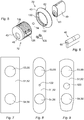
- the lock cylinder can have different designs, for example of the kind that is shown in Fig. 5 or of the kind that is shown in Fig. 6 .
- lock cylinders with a circular cross-section are known. Such lock cylinders often fill substantially the whole hole in the door. According to the present invention it is however that part of the first lock cylinder protection etc. which protrudes into the hole in the door which substantially fills the hole in the door.
- the lock cylinder is thus only configured to be positioned in the first recess.
- the cross-sectional area of the first recess is thus substantially smaller than the cross-sectional area of that part of the first lock cylinder protection which protrudes into the hole in the door. It is possible to configure the first recess according to the present invention for receiving a lock cylinder which has a substantially circular cross-section.
- the lock cylinder has however another cross-sectional shape, for example an oval cross-sectional shape, such as the lock cylinder which is shown in Fig. 5 , or the cross-sectional shape that the lock cylinder shown in Fig. 6 has.
- this or these elements thus extend, in a mounted state, all the way from the second side of the lock cylinder protection to the lock case.
- the same is the case preferably also for possible distance elements in connection with the second lock cylinder protection and the first and second stabilizing member, and possibly also for the holding member, which are mentioned below.
- the first plate may for example be at least 15 cm, preferably at least 20 cm, long (in the vertical direction of the door in a mounted state). It may for example be at least 4.0 cm, preferably at least 5.0 cm, wide, in a direction crosswise to the length. It can have a thickness of for example at least 1.0 mm, preferably at least 2.0 mm, or at least 3.00 mm.
- the plate is preferably made of metal, for example of a steel alloy, preferably a hard manganese steel alloy. The same preferred dimensions and materials are also the case for the second plate, which is mentioned below.
- the first plate hole is preferably circular.
- the hole may have an extension (diameter, if it is circular), of for example between 30 mm and 60 mm, preferably between 35 mm and 45 mm.
- the same preferred dimensions are the case for the second, third and fourth plate hole which are mentioned below.
- the first lock cylinder protection may for example have a length such that it in a mounted state protrudes in at least 1.0 cm, preferably at least 2.0 cm inside the outside of the first plate.
- the same preferred length is the case for the second lock cylinder protection and for the first and second stabilizing member, and may also be the case for the holding member, which are mentioned below.
- the second side of the lock cylinder protection which side in a mounted state abuts against the lock case or against a distance element, preferably has an area of at least 2.0 cm 2 , preferably at least 4.0 cm 2 , most preferred at least 5.0 cm 2 , since such an abutment surface makes the construction more stable.
- the corresponding preferred dimension is the case for possible distance elements and for the second side of the second lock cylinder protection, the first stabilizing member and the second stabilizing member which are mentioned below. The same dimension may also be case for the second side of the holding member which is mentioned below.
- the first surface of the first lock cylinder protection preferably has an area of at least 10 cm 2 , more preferred at least 15 cm 2 and most preferred at least 20 cm 2 in order to give a sufficient stability to the construction when this surface abuts against the first plate.
- Corresponding preferred dimensions are the case for the first surface of the second lock cylinder protection which is mentioned below.
- the corresponding first surface of the first stabilizing member preferably has an area of at least 8 cm 2 , more preferred at least 12 cm 2 and most preferred at least 16 cm 2 .
- the same preferred dimension is the case for the corresponding surface of the second stabilizing member and can also be the case for the corresponding surface of the holding member.
- the first lock cylinder protection is preferably configured such that the lock cylinder can be locked in position in the first recess with locking means which in a mounted state is not available to a user.
- An embodiment of the door lock device according to the invention is defined in claim 2.
- the first attachment means is implemented in a simple and secure manner. Since the screws do not reach to the outside of the door, the security of the device is increased.
- the first lock cylinder protection has only one hole on the first side, i.e. the first lock cylinder protection hole. This makes the device very safe against burglary.
- a further embodiment of the door lock device according to the invention is defined in claim 3. Through this embodiment, a high stability and security is achieved.
- a further embodiment of the door lock device according to the invention is defined in claim 4. Since the part with the first surface can be moved to different positions relative to the first recess, a flexibility is achieved with the lock protection in order to be able to adapt it to different construction cases. Since the adjustable part can also be locked in a selected position, the lock protection has a high security, since in a locked position, the lock cylinder protection functions as a fixed unit. A high security is achieved since said locking means is not available from the outside of the door (and neither from the inside of the door).
- a further embodiment of the door lock device according to the invention is defined in claim 5.
- a high stability and security is achieved through the design of the first stabilizing member and possible distance elements.
- the plate, the stabilizing member, possible distance elements and the lock case form in a mounted state a stable unit, which makes the whole door lock construction very stable and safe.
- the portion of the first stabilizing member which comprises said first surface can, according to an embodiment, constitute a part the position of which can be adjusted in a direction which is substantially perpendicular to the surface of the door, as seen in a mounted state, relative to that portion of the first stabilizing member which comprises said second side, wherein this adjustable part can be locked in a selected position with the help of a locking means which, in a mounted state, is not available from the outside of the door (and neither from the inside of the door).
- a high flexibility is achieved with the first stabilizing member. It is thereby possible to adjust how much the second side protrudes into the door in a mounted state. It is therefore for example possible to ensure that in a mounted state the second side reaches the lock case and that therefore no distance element is needed in order to reach the lock case.
- a further embodiment of the door lock device according to the invention is defined in claim 6.
- the second attachment means is realized in a simple manner.
- a further feature of the door lock device according to the invention is defined in claim 1. Through a second plate the stability and the security are further increased.
- the second plate may be constructed and dimensioned in the same manner as the first plate.
- a further feature of the door lock device according to the invention is defined in claim 1.
- a lock turning mechanism is thus used for the inside of the door instead of a lock cylinder.
- the holding member thus contributes to hold the lock turning mechanism in position in a secure manner.
- That portion of the holding member which comprises said first surface can, according to an embodiment, constitute a part the position of which can be adjusted in a direction which is substantially perpendicular to the surface of the door, as seen in a mounted state, relative to that portion of the holding member which comprises said second side, wherein this adjustable part can be locked in a selected position with the help of a locking means which, in a mounted state, is not available from the inside of the door (and neither from the outside of the door).
- a further feature of the door lock device according to the invention is defined in claim 1. Through this feature, the stability of the construction is increased also when using a lock turning mechanism on the inside of the door.
- a further embodiment of the door lock device according to the invention is defined in claim 7.
- a high stability and security are achieved through the design of the second stabilizing member and possible distance elements.
- the plate, the stabilizing member, possible distance elements and the lock case form, together with the corresponding parts at the outside of the lock case, in a mounted state a stable unit, which makes the whole door lock construction very stable and safe.
- That portion of the second stabilizing member which comprises said first surface can, according to an embodiment, constitute a part the position of which can be adjusted in a direction which is substantially perpendicular to the surface of the door, as seen in a mounted state, relative to that portion of the second stabilizing member which comprises said second side, wherein this adjustable part can be locked in a selected position with the help of a locking means which, in a mounted state, is not available from the inside of the door (and neither from the inside of the door).
- a further embodiment of the door lock device according to the invention is defined in claim 8.
- This embodiment has the advantage that no extra screws or screw holes are needed in the plates for safely arranging the plates at the door. This simplifies essentially the mounting of the door lock device at a door.
- a door according to the invention is defined in claim 9.
- This door has the advantage that it has a door lock device according to the invention, which makes the door/lock-construction very stable and secure against burglary.
- a method according to the invention is defined in claim 10. With this method a door according to the invention is realized, with the advantages that this door has, in a simple manner.
- FIG. 10 shows for the purpose of clarity an exploded view of a door 30 with a door lock device.
- the door 30 has a first door hole 21 which extends through the door from its outside 31 to its inside 32.
- the door also has a second door hole 22 which also extends from the outside 31 of the door to the inside 32 of the door.
- a lock case 23 is arranged in the door hole 21 .
- a lock cylinder 40 is arranged in the first door hole 21, (the lock cylinder is shown in one embodiment in Fig. 5 and in another in Fig. 6 ).
- the lock cylinder is arranged in a first lock cylinder protection 41.
- the lock cylinder 40 extends from the outside 31 of the door into the door hole 21 to the lock case 23 such that the lock cylinder 40 can interact with the lock case 23 in order to lock and unlock the lock.
- the door lock device also has a first plate 51 with a first plate hole 53 and a second plate hole 54.
- the plate 51 abuts, in a mounted state, against the outside 31 of the door such that the first plate hole 53 coincides with the first door hole 21 and the second plate hole 54 coincides with the second door hole 22.
- Different examples of the design of such a first plate is shown in Fig. 7-9 .
- the door lock device also comprises a second plate 52 with a third plate hole 55 and a fourth plate hole 56.
- the second plate 52 abuts in a mounted state against the inside 32 of the door.
- the third plate hole 55 coincides thereby with the first door hole 21 and the fourth plate hole 56 coincides with the second door hole 22.
- the second plate 52 can have the same appearance as the first plate 51.
- Fig. 7-9 thus also show examples of different embodiments of the second plate 52.
- the plates 51, 52 may also possibly have a further hole 122.
- This hole 122 is intended for a screw which goes into or through the lock case 23 which is mounted in the door.
- Fig. 9 shows another hole 120.
- the hole 120 is intended for a door handle, which is used in certain door constructions and which is connected to the lock case 23 which is arranged in the door.
- the first lock cylinder protection 41 is shown in more detail in Fig. 1 and 2 .
- This lock cylinder protection 41 has a first side 43 which in a mounted state lies outside the door surface and outside the first plate 51.
- the lock cylinder protection 41 has a second side 45 which in a mounted state lies in the door 30 in the door hole 21.
- the lock cylinder protection 41 has a first recess 47.
- This recess 47 has a cross-sectional dimension which is adapted for receiving the lock cylinder 40.
- the recess 47 extends from the second side 45 towards the first side 43 but not all the way to the first side 43.
- there is a first lock cylinder protection hole 49 which has a smaller cross-sectional dimension than the first recess 47 and than the lock cylinder 40 and which extends from the first recess 47 out through the first side 43.
- a key can thus be inserted in through the first lock cylinder protection hole 49 into a keyhole 60 in the lock cylinder 40 (see Fig. 5 and 6 ) in order to lock or unlock the lock.
- the lock cylinder 40 can be locked in position in the first recess 47 for example in that one or more lock screws 128 (see Fig. 5 ) are screwed into holes 126 and thereby lock the lock cylinder 40 fixed in the lock cylinder protection 41.
- the lock cylinder protection 41 has a first surface 62 which in a mounted state abuts against the surface of the first plate 51 around the first plate hole 53.
- Fig. 2 thus shows a sealing packing 124 arranged in a recess in the first surface 62.
- Fig. 2 shows also another sealing packing 124 which seals against the lock cylinder 40 when it is inserted in the recess 47.
- the first lock cylinder protection 41 is held in position at the door 30 with the help of a first attachment means 64 in the form of two screws (one such screw is shown in Fig. 10 ).
- the screws 64 extend from the inside 32 of the door and are connected to the first lock cylinder protection 41 by being screwed into screw holes 68 in the first lock cylinder protection 41. These screw holes 68 extend from the second side 45 but not through the whole first lock cylinder protection 41 to its first side 43.
- the first surface 62 thus exerts a pressure force against the first plate 51 in the direction towards the outside 31 of the door.
- the first plate 51 is thus held in position against the outside of the door.
- the first lock cylinder protection 41 can have such a length that it in a mounted state reaches the surface of the lock case 23 in such a manner that the second side 45 of the lock cylinder protection 41 abuts directly against the surface of the lock case when the lock cylinder protection 41 is held attached at the door with the help of the screws 64.
- the device can comprise one or more distance elements 66 (only shown in the lower part of Fig. 10 ) which are arranged between the second side 45 of the lock cylinder protection 41 and the lock case 23 in such a manner that in a mounted state that side of said distance element which is facing the lock case 23 reaches to the lock case 23 and abuts against the surface of the lock case when the lock cylinder protection 41 is held attached at the door with the help of the screws 64.
- Fig. 1 and 2 it is shown that the portion of the first lock cylinder protection 41 which comprises the first surface 62 constitutes one single solid part together with the portion of the lock cylinder protection 41 which comprises the recess 47.
- Fig. 5 an alternative embodiment is shown where the portion of the lock cylinder protection 41 which comprises the first surface 62 constitutes a separate part 70 the position of which can be adjusted relative to the portion 72 of the first lock cylinder protection 41 which comprises the first recess 47.
- the adjustment can be made possible in that the outer surface of the portion 72 is threaded and in that there is a corresponding internal thread in a hole in the part 70.
- the position of the part 70 can thus be selected in that this part is screwed onto the portion 72 until a selected position has been achieved.
- the part 70 can be locked in the selected position with the help of a locking means 74.
- the locking means 74 is according to this embodiment a ball. This ball 74 can be inserted from the recess 47 (which is hidden in Fig. 5 ) through a hole 132 through the wall of the portion 72 in order to protrude into a selected recess 130 at the part 70. The ball 74 thus locks the part 70 relative to the portion 72 in the selected position.
- Fig. 10 also shows a turning device 76 from a door handle 78.
- the turning device 76 extends from the door handle 78 on the outside 31 or the door into the second door hole 22 to the lock case 23.
- the turning device 76 interacts with the lock case 23 such that you can open and close the door 30 with the help of the door handle 78.
- a first stabilizing member 80 has a first side 82 which in a mounted state lies outside the door surface and outside the first plate 51.
- the stabilizing member 80 has a second side 84 which in a mounted state lies in the door 30 in the second door hole 22.
- the stabilizing member 80 has a first surface 86 which in a mounted state abuts, directly or indirectly, against the surface of the first plate 51 around the second plate hole 54.
- a door handle 78 on the inside 32 of the door 30 there is a door handle 78 on the inside 32 of the door 30.
- the door handle interacts with the turning device 76 which extends from the inside 32 of the door into the door hole 22 to the lock case 23. You can thus open and close the door with the help of the door handle 78 on the inside of the door 30, in that the turning device 76 interacts with the lock case 23.
- the turning device 76 can for example be a through shaft which extends through the whole second hole 22 and through the lock case 23.
- a second stabilizing member 110 is arranged in a corresponding manner as the first stabilizing member 80.
- the second stabilizing member 110 thus has a first side 82 which in a mounted state lies inside the door surface on the inside 32 of the door and inside the second plate 52.
- a second side 84 lies in a mounted state in the door in the second door hole 22.
- a first surface 86 of the second stabilizing member 110 abuts in a mounted state directly or indirectly against the second plate 52 around the fourth plate hole 56.
- a second attachment means 65 in the form of two screws holds the first stabilizing member 80 and the second stabilizing member 110 attached.
- the screws 65 extend through a flat member 111 at the door handle 78, through the second stabilizing member 110, through the distance element 66, through, or at the side of, the lock case 23, through further distance elements 66, through the first stabilizing member 80 and through a flat member 87 arranged at the door handle 78 on the outside of the door, such that the screws 65 are screwed into sex bolts 65b.
- the screws 65 can be screwed into threaded screw holes in the first stabilizing member 80, which screw holes extend from the second side 84 but which do not reach to the first side 86 (i.e. in a similar manner as the screws 64 are screwed into the screw holes 68 in the first lock cylinder protection 41).
- the screws 65 exert a force on the first stabilizing member 80 in the direction towards the door such that the first surface 86 of the first stabilizing member 80 exerts a pressure force against the first plate 51 in the direction towards the outside of the door such that the first plate 51 is held in position against the outside of the door.
- the screws 65 exert a force on the second stabilizing member 110 in the direction in towards the door 30 such that the first surface 86 of the second stabilizing member 110 exerts a pressure force against the second plate 52 in the direction towards the inside 32 of the door such that the second plate 52 is held in position against the inside 32 of the door.
- the first stabilizing member 80 can have such a length that it in a mounted state reaches a surface of the lock case 23 such that it abuts with its second side 84 against the surface of the lock case when the first stabilizing member 80 is held attached at the door with the help of the screws 65.
- the second stabilizing member 110 can have a length such that it reaches the lock case 23 and such that it abuts with its second side 84 against the lock case when the stabilizing member 110 is held attached with the help of the screws 65.
- one of more distance elements 66 can be arranged also between the second side 84 of the second stabilizing member and the lock case 23 such that that side of the distance elements which is facing the lock case 23 abuts against the lock case when the second stabilizing member 110 is held attached at the door with the help of the screws 65.
- a second lock cylinder protection 91 is arranged from the inside of the door. Such a second lock cylinder protection 91 is shown in Fig. 3 and 4 .
- the second lock cylinder protection 91 has a similar construction as the first lock cylinder protection 41.
- the second lock cylinder protection 91 thus has a second recess 93 which is adapted to receive a lock cylinder 40.
- the recess 93 extends from the second side 45 towards the first side 43 but not all the way to the first side.
- a second lock cylinder protection hole 95 which has a smaller cross-sectional dimension than the second recess 93 and than the lock cylinder 40 extends however from the second recess 93 out through the first side 43 in a corresponding manner as at the first lock cylinder protection 41.
- a key may thus interact with a lock cylinder 40 which is arranged in the recess 93 via the second lock cylinder protection hole 95.
- the second lock cylinder protection 91 differs however from the first lock cylinder protection 41 in that there are through screw holes 130, which extend from the first side 43 to the second side 45.
- screw holes 130 are intended for the first attachment means, that is the screws 64. Furthermore, there are two screw holes 132 which extend from the first side 43 into the recess 93. These screw holes 132 are intended for screws which are screwed through holes in a lock cylinder 40 which is arranged in the recess 93.
- the second lock cylinder protection 91 has a first surface 62 which in a mounted state, directly or indirectly, abuts against the surface of the second plate 52 around the third plate hole 55.
- the screws 64 hold the second lock cylinder protection 91 attached at the door.
- the screws thereby exert a force on the second lock cylinder protection 91 in the direction towards the door (in that they are screwed into the screw holes 68 in the first lock cylinder protection 41) such that the first surface 62 of the second lock cylinder protection 91 exerts a pressure force against the second plate 52 in the direction towards the inside 32 of the door. In such a manner, the second plate 52 is held in position against the inside 32 of the door.
- the second lock cylinder protection 91 can have such a length that it in a mounted state reaches the lock case 23 such that the second side 45 abuts against the lock case 23 when the second lock cylinder protection 91 is held attached at the door with the help of the screws 64.
- one or more distance elements 66 can be arranged between the second side 45 of the second lock cylinder protection 91 and the lock case 23 such that that side of the distance elements which is facing the lock case 23 reaches the lock case and abuts against the surface of the lock case when the second lock cylinder protection 91 is held attached at the door with the help of the screws 64.
- That portion of the second lock cylinder protection 91 which comprises said first surface 62 can, according to a not shown embodiment, constitute a part the position of which can be adjusted in a direction which is substantially perpendicular to the surface of the door, as seen in a mounted state, relative to that portion of the second lock cylinder protection 91 which comprises said second recess 93, wherein this adjustable part can be locked in a selected position with the help of a locking means which, in a mounted state, is not available from the inside of the door.
- Fig. 11 shows an embodiment according to the invention which differs from the example in Fig. 10 in that there is a lock turning mechanism 100 at the inside of the door at the first door hole 21 and in that there at the second door hole 22 are no door handles or no turning device similar to that which has been shown in connection with Fig. 10 .
- a holding member 101 which has a first side 43 which in a mounted state lies inside the door surface on the inside 32 of the door and inside the second plate 52.
- the holding member 101 has a second side 45 which in a mounted state lies in the door in the first door hole 21.
- a lock turning mechanism 100 extends through the holding member 101 to the lock case 23 such that the lock turning mechanism can interact with the lock case 23 in order to lock and unlock the lock.
- the holding member 101 has a first surface (corresponding to the surface 62 which has been described above) which in a mounted state abuts, directly or indirectly, against the second plate 52 around the third plate hole 55.
- Screws 64 hold the holding member 101 attached at the door such that the holding member 101 exerts a force in the direction towards the door such that the first surface of the holding member 101 exerts a pressure force against the second plate 52 in the direction towards the inside 32 of the door.
- the second plate 52 is thereby held in position against the inside of the door.
- the holding member 101 can possibly have such a length that it in a mounted state reaches the lock case 23, such that the second side 45 abuts against the surface of the lock case when the holding member 101 is held attached at the door with the help of the screws 64.
- one of more distance elements 66 can possibly be arranged between the second side 45 of the holding member 101 and the lock case 23 such that in a mounted state that side of the distance elements which is facing the lock case 23 reaches the lock case and abuts against the surface of the lock case when the holding member 101 is held attached at the door with the help of the screws 64.
- the first stabilizing member 80 and the second stabilizing member 110 do not, according to this embodiment, need to have any holes, except for holes for the screws 65. These holes for the screws are extending through the second stabilizing member 110 and can be extending through the first stabilizing member 80, and thereby be screwed into for example sex bolts 65b. According to a preferred embodiment, the first stabilizing member 80 does however have threaded screw holes which do not reach out through the first side 82, whereby no sex bolts 65b are needed.
- possible distance elements 66 according to the embodiment of Fig. 11 only need to have holes for the screws 65.
- that portion of the first stabilizing member 80 and/or the second stabilizing member 110 and/or the holding member 101 which comprises said first surface 86 can constitute a part the position of which can be adjusted in a direction which is substantially perpendicular to the surface of the door, as seen in a mounted state, relative to that portion of the first stabilizing member 80, the second stabilizing member 110 and the holding member 101, respectively, which comprises said second side 84, 45, wherein this adjustable part can be locked in a selected position with the help of a locking means which, in a mounted state, is not available from the outside or the inside of the door.
- the respective stabilizing member 80, 110 can, according to a not shown embodiment, be attached at the respective plate 51, 52 with the help of further screws.
- the first stabilizing member 80 can have two or more threaded screw holes in through the first surface 86, but which do not reach out through the first stabilizing member 80.
- the plate 51 can have corresponding non-threaded holes for screws. In such a manner, screws can be screwed (before mounting the plate at the door) from the inside of the plate 51 through the holes in the plate 51 into the screw holes in the surface 86 in order to further ensure that the first stabilizing member 80 is held attached at the plate 51.
- non-threaded screw holes can be arranged which extend in through the surface 86 out through the outside of the first stabilizing member 80. Screws can then for example be screwed in from the outside, through these non-threaded screw holes and into corresponding threaded screw holes in the plate 51 (or, alternatively, be screwed into nuts or sex bolts at the inside of the plate 51).
- the second stabilizing member 110 can be connected to the plate 52 via further threaded or non-threaded screw holes in through the surface 86 on the second stabilizing member 110.
- corresponding screw holes can also be arranged in the upper part in the first surface 62 of the first and/or second lock cylinder protection 41, 91 or of the holding member 101, with corresponding threaded or non-threaded holes at the respective plate 51, 52.
- a door 30 according to the invention comprises a door lock device according to the invention in a mounted state.
- Fig. 11 thus illustrate an embodiment of a door according to the invention.
- a method of mounting a door lock construction according to the invention can comprise the following steps.
- a lock case 23, at least one lock cylinder 40 and a door lock device according to the invention are provided.
- the lock case 23 is arranged in the door 30 at a position intended therefor in level with the first door hole 21 and the second door hole 22.
- the lock cylinder 40 is arranged in the recess 47 in the first lock cylinder protection 41.
- the door lock device is arranged as has been described above at the door with the help of the screws 64, 65.
Landscapes
- Engineering & Computer Science (AREA)
- Mechanical Engineering (AREA)
- Structural Engineering (AREA)
- Lock And Its Accessories (AREA)
Claims (10)
- Türverriegelungsvorrichtung, die für eine Tür (30) mit einem ersten Türloch (21) gestaltet ist, das sich von der Außenseite (31) der Tür zur Innenseite (32) der Tür erstreckt und in dem ein Schließzylinder (40) so angeordnet werden soll, dass er sich von der Außenseite (31) der Tür in das erste Türloch (21) in der Richtung zu einem Schlosskasten (23) hin erstreckt, der in der Tür (30) in einer solchen Weise angeordnet ist, dass der Schließzylinder (40) mit dem Schlosskasten (23) zusammenwirken kann, um das Schloss zu verriegeln und zu entriegeln, wobei die Türverriegelungsvorrichtung umfasst:eine erste Platte (51) mit einem ersten Plattenloch (53), wobei die Platte (51) dazu bestimmt ist, an der Außenseite (31) der Tür so anzuliegen, dass sich das erste Plattenloch (53) mit dem ersten Türloch (21) deckt,einen ersten Schließzylinderschutz (41) mit einer ersten Seite (43), die in einem montierten Zustand außerhalb der Türoberfläche und außerhalb der ersten Platte (51) liegt, einer zweiten Seite (45), die in einem montierten Zustand in der Tür (30) in dem ersten Türloch (21) liegt, wobei der erste Schließzylinderschutz (41) eine erste Aussparung (47) mit einer Querschnittsabmessung aufweist, die dafür angepasst ist, einen Schließzylinder (40) aufzunehmen, wobei sich die Aussparung von der zweiten Seite (45) zur ersten Seite (43), aber nicht den gesamten Weg zur ersten Seite erstreckt, wo sich jedoch ein erstes Schließzylinderschutzloch (49), das eine kleinere Querschnittsabmessung als die erste Aussparung (47) und als der Schließzylinder (40) aufweist, von der ersten Aussparung (47) durch die erste Seite (43) hinaus erstreckt, wobei das erste Schließzylinderschutzloch (49) so gestaltet ist, dass in einem montierten Zustand ein Schlüssel durch das erste Schließzylinderschutzloch (49) mit dem in der ersten Aussparung (47) positionierten Schließzylinder (40) zusammenwirken kann, indem entweder der Schlüssel in ein Schlüsselloch (60) in dem Schließzylinder (40) eingeführt wird oder der Schlüssel in einer anderen Weise mit dem Schließzylinder (40) kommuniziert, wobei der erste Schließzylinderschutz (41) eine erste Oberfläche (62) umfasst, die dafür gestaltet ist, in einem montierten Zustand direkt oder über ein oder mehrere weitere Elemente an der Oberfläche der ersten Platte (51) um das erste Plattenloch (53) und somit um das erste Türloch (21) herum anzuliegen,ein erstes Befestigungsmittel (64), das dazu bestimmt ist, den ersten Schließzylinderschutz (41) an der Tür befestigt zu halten, wobei das erste Befestigungsmittel (64) dazu bestimmt ist, sich von der Innenseite (32) der Tür zu erstrecken und mit dem ersten Schließzylinderschutz (41) verbunden zu werden, ohne sich durch die erste Seite (43) des ersten Schließzylinderschutzes (41) heraus zu erstrecken, wobei das erste Befestigungsmittel (64) dafür vorgesehen ist, auf den ersten Schließzylinderschutz (41) in der Richtung zur Tür hin eine Kraft auszuüben, so dass durch diese Kraft die erste Oberfläche (62) eine Druckkraft gegen die erste Platte (51) in der Richtung zur Außenseite (31) der Tür hin ausübt, so dass die erste Platte (51) gegen die Außenseite der Tür in Position gehalten wird,wobei entwedera) der erste Schließzylinderschutz (41) eine solche Länge aufweist, dass er in einem montierten Zustand eine Oberfläche des in der Tür montierten Schlosskastens (23) erreicht und mit seiner zweiten Seite (45) an der Oberfläche des Schlosskastens (23) anliegt, wenn der erste Schließzylinderschutz (41) mit Hilfe des ersten Befestigungsmittels (64) an der Tür befestigt gehalten wird,
oderb) die Türverriegelungsvorrichtung mindestens ein Abstandselement (66) umfasst, das dafür gestaltet ist, zwischen der zweiten Seite (45) des ersten Schließzylinderschutzes (41) und dem in der Tür montierten Schlosskasten (23) angeordnet zu werden, so dass in einem montierten Zustand jene Seite des Abstandselements (66), die dem Schlosskasten (23) in der Tür zugewandt ist, eine Oberfläche des Schlosskastens (23) erreicht und an dieser Oberfläche anliegt, wenn der erste Schließzylinderschutz (41) mit Hilfe des ersten Befestigungsmittels (64) an der Tür befestigt gehalten wird,wobei die Türverriegelungsvorrichtung umfasst:eine zweite Platte (52) mit einem dritten Plattenloch (55), wobei die Platte (52) dazu bestimmt ist, an der Innenseite (32) der Tür so anzuliegen, dass sich das dritte Plattenloch (55) mit dem ersten Türloch (21) deckt, undeinen Schlossdrehmechanismus (100), der dafür vorgesehen ist, das Schloss von der Innenseite der Tür her ohne Verwendung eines Schlüssels verriegeln und entriegeln zu können, wobei die Türverriegelungsvorrichtung ferner umfasst:ein Halteelement (101) mit einer ersten Seite (43), die in einem montierten Zustand innerhalb der Türoberfläche auf der Innenseite (32) der Tür und innerhalb der zweiten Platte (52) liegt, einer zweiten Seite (45), die in einem montierten Zustand in der Tür in dem ersten Türloch (21) liegt, wobei sich in einem montierten Zustand der Schlossdrehmechanismus (100) durch das Halteelement (101) hindurch zum Schlosskasten (23) erstreckt, so dass in einem montierten Zustand der Schlossdrehmechanismus (100) zum Verriegeln und Entriegeln des Schlosses mit dem Schlosskasten (23) zusammenwirken kann, wobei das Halteelement (101) eine erste Oberfläche umfasst, die dafür gestaltet ist, in einem montierten Zustand direkt oder über ein oder mehrere weitere Elemente an der Oberfläche der zweiten Platte (52) um das dritte Plattenloch (55) und somit um das erste Türloch (21) herum anzuliegen,wobei das erste Befestigungsmittel (64) auch dazu bestimmt ist, das Halteelement (101) an der Tür befestigt zu halten, wobei das erste Befestigungsmittel (64) dafür vorgesehen ist, auf das Halteelement (101) in der Richtung zur Tür hin eine Kraft auszuüben, so dass durch diese Kraft die erste Oberfläche des Halteelements (101) eine Druckkraft gegen die zweite Platte (52) in der Richtung zur Innenseite (32) der Tür hin ausübt, so dass die zweite Platte (52) gegen die Innenseite der Tür in Position gehalten wird,wobei entwedera) das Halteelement (101) eine solche Länge aufweist, dass es in einem montierten Zustand eine Oberfläche des in der Tür montierten Schlosskastens (23) erreicht und mit seiner zweiten Seite (45) an der Oberfläche des Schlosskastens (23) anliegt, wenn das Halteelement (101) mit Hilfe des ersten Befestigungsmittels (64) an der Tür befestigt gehalten wird,
oderb) die Türverriegelungsvorrichtung mindestens ein Abstandselement (66) umfasst, das dafür gestaltet ist, zwischen der zweiten Seite (45) des Halteelements (101) und dem in der Tür montierten Schlosskasten (23) angeordnet zu werden, so dass in einem montierten Zustand jene Seite des Abstandselements (66), die dem Schlosskasten (23) in der Tür zugewandt ist, eine Oberfläche des Schlosskastens erreicht und an dieser Oberfläche anliegt, wenn das Halteelement (101) mit Hilfe des ersten Befestigungsmittels (64) an der Tür befestigt gehalten wird. - Türverriegelungsvorrichtung nach Anspruch 1, wobei das erste Befestigungsmittel (64) mindestens zwei Schrauben umfasst, die in einem montierten Zustand mit dem ersten Schließzylinderschutz (41) verbunden sind, indem sie in Schraubgewindelöcher (68) im ersten Schließzylinderschutz (41) eingeschraubt sind, wobei sich die Schraubgewindelöcher (68) von der zweiten Seite (45) des ersten Schließzylinderschutzes (41), jedoch nicht durch den gesamten ersten Schließzylinderschutz (41) hindurch zu dessen erster Seite (43) erstrecken.
- Türverriegelungsvorrichtung nach einem der vorhergehenden Ansprüche, wobei jener Abschnitt des ersten Schließzylinderschutzes (41), der die erste Oberfläche (62) umfasst, zusammen mit jenem Abschnitt des ersten Schließzylinderschutzes (41), der die erste Aussparung (47) umfasst, ein einziges solides Teil bildet.
- Türverriegelungsvorrichtung einem der Ansprüche 1 bis 2, wobei jener Teil des ersten Schließzylinderschutzes (41), der die erste Oberfläche (62) umfasst, ein Teil (70) bildet, dessen Position in einer Richtung, die, bei Betrachtung in einem montierten Zustand, im Wesentlichen senkrecht zur Oberfläche der Tür ist, in Bezug auf jenen Abschnitt (72) des ersten Schließzylinderschutzes (41), der die erste Aussparung (47) umfasst, verstellbar ist, wobei dieses verstellbare Teil (70) mit Hilfe eines Verriegelungsmittels (74), das in einem montierten Zustand von der Außenseite der Tür her nicht zugänglich ist, in einer ausgewählten Position verriegelt werden kann.
- Türverriegelungsvorrichtung nach einem der vorhergehenden Ansprüche, die für eine Tür (30) gestaltet ist, die zusätzlich ein zweites Türloch (22) aufweist, das sich von der Außenseite (31) der Tür zur Innenseite (32) der Tür erstreckt und in dem zum Beispiel eine Drehvorrichtung (76) von einem Türgriff (78) so angeordnet werden soll, dass sie sich von der Außenseite (31) der Tür in das zweite Türloch in der Richtung zu einem Schlosskasten (23) hin erstreckt, der in der Tür in einer solchen Weise angeordnet ist, dass die Drehvorrichtung (76) mit dem Schlosskasten (23) zusammenwirken kann, um die Tür (30) zu öffnen und zu schließen,
wobei die erste Platte (51) ein zweites Plattenloch (54) umfasst, das so angeordnet ist, dass sich in einem montierten Zustand das zweite Plattenloch (54) mit dem zweiten Türloch (22) deckt, und wobei die Türverriegelungsvorrichtung umfasst:ein erstes Stabilisierungselement (80) mit einer ersten Seite (82), die in einem montierten Zustand außerhalb der Türoberfläche und außerhalb der ersten Platte (51) liegt, einer zweiten Seite (84), die in einem montierten Zustand in der Tür in dem zweiten Türloch (22) liegt, wobei das erste Stabilisierungselement eine erste Oberfläche (86) umfasst, die dafür gestaltet ist, in einem montierten Zustand direkt oder über ein oder mehrere weitere Elemente an der Oberfläche der ersten Platte (51) um das zweite Plattenloch (54) und somit um das zweite Türloch (22) herum anzuliegen,ein zweites Befestigungsmittel (65), das dazu bestimmt ist, das erste Stabilisierungselement (80) an der Tür befestigt zu halten, wobei das zweite Befestigungsmittel (65) dazu bestimmt ist, sich von der Innenseite (32) der Tür zu erstrecken und mit dem ersten Stabilisierungselement (80) oder mit einem äußerlich des ersten Stabilisierungselements (80) angeordneten Element (87) verbunden zu werden, wobei das zweite Befestigungsmittel (65) dafür vorgesehen ist, auf das erste Stabilisierungselement (80) in der Richtung zur Tür hin eine Kraft auszuüben, so dass durch diese Kraft die erste Oberfläche (86) des ersten Stabilisierungselements (80) eine Druckkraft gegen die erste Platte (51) in der Richtung zur Außenseite (31) der Tür hin ausübt, so dass die erste Platte (51) gegen die Außenseite der Tür in Position gehalten wird,wobei entwedera) das erste Stabilisierungselement (80) eine solche Länge aufweist, dass es in einem montierten Zustand eine Oberfläche des in der Tür montierten Schlosskastens (23) erreicht und mit seiner zweiten Seite (84) an der Oberfläche des Schlosskastens anliegt, wenn das erste Stabilisierungselement (80) mit Hilfe des zweiten Befestigungsmittels (65) an der Tür befestigt gehalten wird,
oderb) die Türverriegelungsvorrichtung mindestens ein Abstandselement (66) umfasst, das dafür gestaltet ist, zwischen der zweiten Seite (84) des ersten Stabilisierungselements (80) und dem in der Tür montierten Schlosskasten (23) angeordnet zu werden, so dass in einem montierten Zustand jene Seite des Abstandselements (66), die dem Schlosskasten (23) in der Tür zugewandt ist, eine Oberfläche des Schlosskastens erreicht und an dieser Oberfläche anliegt, wenn das erste Stabilisierungselement (80) mit Hilfe des zweiten Befestigungsmittels (65) an der Tür befestigt gehalten wird. - Türverriegelungsvorrichtung nach Anspruch 5, wobei das zweite Befestigungsmittel mindestens zwei Schrauben (65) umfasst.
- Türverriegelungsvorrichtung nach einem der vorhergehenden Ansprüche, die für eine Tür gestaltet ist, die zusätzlich ein zweites Türloch (22) aufweist, das sich von der Außenseite (31) der Tür zur Innenseite (32) der Tür erstreckt und in dem zum Beispiel eine Drehvorrichtung (76) von einem Türgriff (78) so angeordnet werden soll, dass sie sich von der Innenseite (32) der Tür in das zweite Türloch (22) in der Richtung zu einem Schlosskasten (23) hin erstreckt, der in der Tür in einer solchen Weise angeordnet ist, dass die Drehvorrichtung (76) mit dem Schlosskasten (23) zusammenwirken kann, um die Tür zu öffnen und zu schließen,
wobei die zweite Platte (52) ein viertes Plattenloch (56) umfasst, das so angeordnet ist, dass sich in einem montierten Zustand das vierte Plattenloch (56) mit dem zweiten Türloch (22) deckt, und wobei der Türverriegelungsschutz umfasst:ein zweites Stabilisierungselement (110) mit einer ersten Seite (82), die in einem montierten Zustand innerhalb der Türoberfläche auf der Innenseite (32) der Tür und innerhalb der zweiten Platte (52) liegt, einer zweiten Seite (84), die in einem montierten Zustand in der Tür in dem zweiten Türloch (22) liegt, wobei das zweite Stabilisierungselement (110) eine erste Oberfläche (86) umfasst, die dafür gestaltet ist, in einem montierten Zustand direkt oder über ein oder mehrere weitere Elemente an der Oberfläche der zweiten Platte (52) um das vierte Plattenloch (56) und somit um das zweite Türloch (22) herum anzuliegen,ein zweites Befestigungsmittel (65), das dazu bestimmt ist, das zweite Stabilisierungselement (110) an der Tür befestigt zu halten, wobei das zweite Befestigungsmittel (65) dazu bestimmt ist, sich von der Innenseite (32) der Tür zu erstrecken und mit dem zweiten Stabilisierungselement (110) oder mit einem innerhalb des zweiten Stabilisierungselements (110) angeordneten Element (111) verbunden zu werden, wobei das zweite Befestigungsmittel (65) dafür vorgesehen ist, auf das zweite Stabilisierungselement (110) in der Richtung zur Tür hin eine Kraft auszuüben, so dass durch diese Kraft die erste Oberfläche (86) des zweiten Stabilisierungselements (110) eine Druckkraft gegen die zweite Platte (52) in der Richtung zur Innenseite (32) der Tür hin ausübt, so dass die zweite Platte (52) gegen die Innenseite der Tür in Position gehalten wird,wobei entwedera) das zweite Stabilisierungselement (110) eine solche Länge aufweist, dass es in einem montierten Zustand eine Oberfläche des in der Tür montierten Schlosskastens (23) erreicht und mit seiner zweiten Seite (84) an der Oberfläche des Schlosskastens anliegt, wenn das zweite Stabilisierungselement (110) mit Hilfe des zweiten Befestigungsmittels (65) an der Tür befestigt gehalten wird,
oderb) die Türverriegelungsvorrichtung mindestens ein Abstandselement (66) umfasst, das dafür gestaltet ist, zwischen der zweiten Seite (84) des zweiten Stabilisierungselements und dem in der Tür montierten Schlosskasten (23) angeordnet zu werden, so dass in einem montierten Zustand jene Seite des Abstandselements, die dem Schlosskasten (23) in der Tür zugewandt ist, eine Oberfläche des Schlosskastens erreicht und an dieser Oberfläche anliegt, wenn das zweite Stabilisierungselement (110) mit Hilfe des zweiten Befestigungsmittels (65) an der Tür befestigt gehalten wird. - Türverriegelungsvorrichtung nach einem der vorhergehenden Ansprüche, wobei die erste Platte (51) und die zweite Platte (52) abgesehen von dem ersten (53), dem zweiten (54), dem dritten (55) und dem vierten (56) Plattenloch keinerlei Löcher aufweisen, die so positioniert sind, dass sie für Schrauben vorgesehen sind, welche die Platten (51, 52) an der Tür befestigt halten sollen, ohne sich zu dem oder durch den in der Tür angeordneten Schlosskasten (23) zu erstrecken.
- Tür (30), umfassend mindestes ein erstes Türloch (21), das sich von der Außenseite (31) der Tür zur Innenseite (32) der Tür erstreckt, einen Schlosskasten (23), der in der Tür in Höhe des ersten Türlochs (21) angeordnet ist, und einen Schließzylinder (40), der so angeordnet ist, dass er sich von der Außenseite (31) der Tür in das erste Türloch (21) in der Richtung zum Schlosskasten (23) hin erstreckt, der in der Tür in einer solchen Weise angeordnet ist, dass der Schließzylinder (40) mit dem Schlosskasten (23) zusammenwirken kann, um das Schloss zu verriegeln und zu entriegeln, wobei die Tür außerdem eine Türverriegelungsvorrichtung nach einem der vorhergehenden Ansprüche umfasst, wobei die Türverriegelungsvorrichtung bestimmungsgemäß an der an der Tür montiert ist.
- Verfahren zur Montage einer Türverriegelungskonstruktion an einer Tür (30), die mindestens ein erstes Türloch (21) aufweist, das sich von der Außenseite (31) der Tür zur Innenseite (32) der Tür erstreckt, wobei das Verfahren umfasst:Bereitstellen eines Schlosskastens (23), mindestens eines Schließzylinders (40) und einer Türverriegelungsvorrichtung nach einem der Ansprüche 1 bis 8,Anordnen des Schlosskastens (23) in der Tür in Höhe des ersten Türlochs (21),Anordnen des Schließzylinders (40) in der ersten Aussparung (47) im ersten Schließzylinderschutz (41),bestimmungsgemäßes Anordnen der Türverriegelungsvorrichtung an der Tür.
Applications Claiming Priority (2)
| Application Number | Priority Date | Filing Date | Title |
|---|---|---|---|
| SE1150681A SE1150681A1 (sv) | 2011-07-14 | 2011-07-14 | Dörrlåsanordning, dörr och förfarande för montering av en dörrlåskonstruktion |
| EP12172960.2A EP2546436B1 (de) | 2011-07-14 | 2012-06-21 | Türverriegelungsvorrichtung, tür und verfahren zur montage einer türverriegelungskonstruktion |
Related Parent Applications (2)
| Application Number | Title | Priority Date | Filing Date |
|---|---|---|---|
| EP12172960.2A Division EP2546436B1 (de) | 2011-07-14 | 2012-06-21 | Türverriegelungsvorrichtung, tür und verfahren zur montage einer türverriegelungskonstruktion |
| EP12172960.2A Division-Into EP2546436B1 (de) | 2011-07-14 | 2012-06-21 | Türverriegelungsvorrichtung, tür und verfahren zur montage einer türverriegelungskonstruktion |
Publications (2)
| Publication Number | Publication Date |
|---|---|
| EP3467237A1 EP3467237A1 (de) | 2019-04-10 |
| EP3467237B1 true EP3467237B1 (de) | 2021-05-12 |
Family
ID=46317255
Family Applications (2)
| Application Number | Title | Priority Date | Filing Date |
|---|---|---|---|
| EP18207622.4A Active EP3467237B1 (de) | 2011-07-14 | 2012-06-21 | Türverriegelungsvorrichtung, tür und verfahren zur montage einer türverriegelungskonstruktion |
| EP12172960.2A Active EP2546436B1 (de) | 2011-07-14 | 2012-06-21 | Türverriegelungsvorrichtung, tür und verfahren zur montage einer türverriegelungskonstruktion |
Family Applications After (1)
| Application Number | Title | Priority Date | Filing Date |
|---|---|---|---|
| EP12172960.2A Active EP2546436B1 (de) | 2011-07-14 | 2012-06-21 | Türverriegelungsvorrichtung, tür und verfahren zur montage einer türverriegelungskonstruktion |
Country Status (3)
| Country | Link |
|---|---|
| EP (2) | EP3467237B1 (de) |
| DK (2) | DK3467237T3 (de) |
| SE (1) | SE1150681A1 (de) |
Families Citing this family (4)
| Publication number | Priority date | Publication date | Assignee | Title |
|---|---|---|---|---|
| SE538657C2 (sv) * | 2013-03-14 | 2016-10-11 | Noway Security Ab | Förstärkningsdel för en dörr, och dörr innefattande en förstärkningsdel |
| JP6289189B2 (ja) * | 2014-02-28 | 2018-03-07 | 株式会社ゴール | 扉厚調整用のカラー |
| WO2021091441A1 (en) * | 2019-11-07 | 2021-05-14 | HESSELBÄCK, Johan | Lock protection and method for arranging of lock protection |
| ES2941182B2 (es) * | 2021-11-17 | 2023-09-18 | Ramos Javier Garcia | Protector para cilindros de cerraduras |
Family Cites Families (4)
| Publication number | Priority date | Publication date | Assignee | Title |
|---|---|---|---|---|
| US3715899A (en) * | 1971-08-09 | 1973-02-13 | Best Lock Corp | Rim cylinder lock mechanism |
| SE426722B (sv) * | 1980-11-14 | 1983-02-07 | Gkn Stenman Ab | Cylinderbehor |
| US4836001A (en) * | 1985-04-01 | 1989-06-06 | Best Lock Corporation | High security lock |
| CH672939A5 (de) * | 1987-03-06 | 1990-01-15 | Ernst Keller |
-
2011
- 2011-07-14 SE SE1150681A patent/SE1150681A1/sv unknown
-
2012
- 2012-06-21 EP EP18207622.4A patent/EP3467237B1/de active Active
- 2012-06-21 EP EP12172960.2A patent/EP2546436B1/de active Active
- 2012-06-21 DK DK18207622.4T patent/DK3467237T3/da active
- 2012-06-21 DK DK12172960.2T patent/DK2546436T3/en active
Also Published As
| Publication number | Publication date |
|---|---|
| DK3467237T3 (da) | 2021-07-26 |
| SE535635C2 (sv) | 2012-10-23 |
| EP2546436B1 (de) | 2019-01-09 |
| SE1150681A1 (sv) | 2012-10-23 |
| EP3467237A1 (de) | 2019-04-10 |
| DK2546436T3 (en) | 2019-04-23 |
| EP2546436A3 (de) | 2017-03-22 |
| EP2546436A2 (de) | 2013-01-16 |
Similar Documents
| Publication | Publication Date | Title |
|---|---|---|
| US4688409A (en) | Drop-bolt door lock assembly | |
| EP2546436B1 (de) | Türverriegelungsvorrichtung, tür und verfahren zur montage einer türverriegelungskonstruktion | |
| AU2008203120A1 (en) | Lock Assembly | |
| CN103649446A (zh) | 圆筒锁 | |
| TW200622074A (en) | Locking mechanism having dual unlocking modes | |
| RU2630655C2 (ru) | Цилиндрический замок с шунтирующим элементом, соединяющим части корпуса | |
| EP2580411A1 (de) | Griffe | |
| US20030041633A1 (en) | Reinforcing bracket for locks | |
| AU620776B2 (en) | Lock mounting pad | |
| EP2450507B1 (de) | Schlossschutz für ein Zylinderschloss | |
| EP2466038B1 (de) | Verbesserungen im Zusammenhang mit Sperranordnungen | |
| AU2019232902A1 (en) | Mogul cylinder lock assembly | |
| EP2778320B1 (de) | Verstärkung für Schloss | |
| CN213927879U (zh) | 安全防盗用燃气配套锁及表箱 | |
| EP1606481A1 (de) | Zylindergehäuse-anordnung | |
| GB2290579A (en) | A door lock escutcheon having load transmitting means | |
| CN103924840A (zh) | 一种锁芯防撬盖 | |
| US20050223760A1 (en) | Safety lock for glass doors | |
| EP1944437B1 (de) | Untrennbarer Schließzylinder | |
| WO2007020622A3 (en) | Mortise lock assembly | |
| JP2003343135A (ja) | ツインロック | |
| CA2555969A1 (en) | Combination deadbolt | |
| EP2418341B1 (de) | Verfahren zur Befestigung eines hinten montierten Schließzylinders an ein Schlossgehäuse | |
| JP2020516795A (ja) | 安全ロックシステム | |
| US20050223764A1 (en) | Retaining mechanism for mortise cylinders |
Legal Events
| Date | Code | Title | Description |
|---|---|---|---|
| PUAI | Public reference made under article 153(3) epc to a published international application that has entered the european phase |
Free format text: ORIGINAL CODE: 0009012 |
|
| STAA | Information on the status of an ep patent application or granted ep patent |
Free format text: STATUS: THE APPLICATION HAS BEEN PUBLISHED |
|
| AC | Divisional application: reference to earlier application |
Ref document number: 2546436 Country of ref document: EP Kind code of ref document: P |
|
| AK | Designated contracting states |
Kind code of ref document: A1 Designated state(s): AL AT BE BG CH CY CZ DE DK EE ES FI FR GB GR HR HU IE IS IT LI LT LU LV MC MK MT NL NO PL PT RO RS SE SI SK SM TR |
|
| STAA | Information on the status of an ep patent application or granted ep patent |
Free format text: STATUS: REQUEST FOR EXAMINATION WAS MADE |
|
| 17P | Request for examination filed |
Effective date: 20191008 |
|
| RBV | Designated contracting states (corrected) |
Designated state(s): AL AT BE BG CH CY CZ DE DK EE ES FI FR GB GR HR HU IE IS IT LI LT LU LV MC MK MT NL NO PL PT RO RS SE SI SK SM TR |
|
| RIC1 | Information provided on ipc code assigned before grant |
Ipc: E05B 15/16 20060101ALN20201208BHEP Ipc: E05B 63/00 20060101ALN20201208BHEP Ipc: E05B 17/20 20060101ALI20201208BHEP Ipc: E05B 9/08 20060101ALI20201208BHEP Ipc: E05B 15/02 20060101AFI20201208BHEP |
|
| GRAP | Despatch of communication of intention to grant a patent |
Free format text: ORIGINAL CODE: EPIDOSNIGR1 |
|
| STAA | Information on the status of an ep patent application or granted ep patent |
Free format text: STATUS: GRANT OF PATENT IS INTENDED |
|
| INTG | Intention to grant announced |
Effective date: 20210118 |
|
| GRAS | Grant fee paid |
Free format text: ORIGINAL CODE: EPIDOSNIGR3 |
|
| GRAA | (expected) grant |
Free format text: ORIGINAL CODE: 0009210 |
|
| STAA | Information on the status of an ep patent application or granted ep patent |
Free format text: STATUS: THE PATENT HAS BEEN GRANTED |
|
| AC | Divisional application: reference to earlier application |
Ref document number: 2546436 Country of ref document: EP Kind code of ref document: P |
|
| AK | Designated contracting states |
Kind code of ref document: B1 Designated state(s): AL AT BE BG CH CY CZ DE DK EE ES FI FR GB GR HR HU IE IS IT LI LT LU LV MC MK MT NL NO PL PT RO RS SE SI SK SM TR |
|
| REG | Reference to a national code |
Ref country code: GB Ref legal event code: FG4D |
|
| REG | Reference to a national code |
Ref country code: CH Ref legal event code: EP |
|
| REG | Reference to a national code |
Ref country code: FI Ref legal event code: FGE |
|
| REG | Reference to a national code |
Ref country code: DE Ref legal event code: R096 Ref document number: 602012075583 Country of ref document: DE |
|
| REG | Reference to a national code |
Ref country code: IE Ref legal event code: FG4D |
|
| REG | Reference to a national code |
Ref country code: AT Ref legal event code: REF Ref document number: 1392268 Country of ref document: AT Kind code of ref document: T Effective date: 20210615 |
|
| REG | Reference to a national code |
Ref country code: DK Ref legal event code: T3 Effective date: 20210719 |
|
| REG | Reference to a national code |
Ref country code: NO Ref legal event code: T2 Effective date: 20210512 |
|
| REG | Reference to a national code |
Ref country code: LT Ref legal event code: MG9D |
|
| REG | Reference to a national code |
Ref country code: AT Ref legal event code: MK05 Ref document number: 1392268 Country of ref document: AT Kind code of ref document: T Effective date: 20210512 |
|
| REG | Reference to a national code |
Ref country code: NL Ref legal event code: MP Effective date: 20210512 |
|
| PG25 | Lapsed in a contracting state [announced via postgrant information from national office to epo] |
Ref country code: AT Free format text: LAPSE BECAUSE OF FAILURE TO SUBMIT A TRANSLATION OF THE DESCRIPTION OR TO PAY THE FEE WITHIN THE PRESCRIBED TIME-LIMIT Effective date: 20210512 Ref country code: BG Free format text: LAPSE BECAUSE OF FAILURE TO SUBMIT A TRANSLATION OF THE DESCRIPTION OR TO PAY THE FEE WITHIN THE PRESCRIBED TIME-LIMIT Effective date: 20210812 Ref country code: LT Free format text: LAPSE BECAUSE OF FAILURE TO SUBMIT A TRANSLATION OF THE DESCRIPTION OR TO PAY THE FEE WITHIN THE PRESCRIBED TIME-LIMIT Effective date: 20210512 Ref country code: HR Free format text: LAPSE BECAUSE OF FAILURE TO SUBMIT A TRANSLATION OF THE DESCRIPTION OR TO PAY THE FEE WITHIN THE PRESCRIBED TIME-LIMIT Effective date: 20210512 |
|
| PG25 | Lapsed in a contracting state [announced via postgrant information from national office to epo] |
Ref country code: SE Free format text: LAPSE BECAUSE OF FAILURE TO SUBMIT A TRANSLATION OF THE DESCRIPTION OR TO PAY THE FEE WITHIN THE PRESCRIBED TIME-LIMIT Effective date: 20210512 Ref country code: RS Free format text: LAPSE BECAUSE OF FAILURE TO SUBMIT A TRANSLATION OF THE DESCRIPTION OR TO PAY THE FEE WITHIN THE PRESCRIBED TIME-LIMIT Effective date: 20210512 Ref country code: PT Free format text: LAPSE BECAUSE OF FAILURE TO SUBMIT A TRANSLATION OF THE DESCRIPTION OR TO PAY THE FEE WITHIN THE PRESCRIBED TIME-LIMIT Effective date: 20210913 Ref country code: LV Free format text: LAPSE BECAUSE OF FAILURE TO SUBMIT A TRANSLATION OF THE DESCRIPTION OR TO PAY THE FEE WITHIN THE PRESCRIBED TIME-LIMIT Effective date: 20210512 Ref country code: PL Free format text: LAPSE BECAUSE OF FAILURE TO SUBMIT A TRANSLATION OF THE DESCRIPTION OR TO PAY THE FEE WITHIN THE PRESCRIBED TIME-LIMIT Effective date: 20210512 Ref country code: GR Free format text: LAPSE BECAUSE OF FAILURE TO SUBMIT A TRANSLATION OF THE DESCRIPTION OR TO PAY THE FEE WITHIN THE PRESCRIBED TIME-LIMIT Effective date: 20210813 Ref country code: IS Free format text: LAPSE BECAUSE OF FAILURE TO SUBMIT A TRANSLATION OF THE DESCRIPTION OR TO PAY THE FEE WITHIN THE PRESCRIBED TIME-LIMIT Effective date: 20210912 |
|
| PG25 | Lapsed in a contracting state [announced via postgrant information from national office to epo] |
Ref country code: NL Free format text: LAPSE BECAUSE OF FAILURE TO SUBMIT A TRANSLATION OF THE DESCRIPTION OR TO PAY THE FEE WITHIN THE PRESCRIBED TIME-LIMIT Effective date: 20210512 |
|
| REG | Reference to a national code |
Ref country code: DE Ref legal event code: R119 Ref document number: 602012075583 Country of ref document: DE |
|
| PG25 | Lapsed in a contracting state [announced via postgrant information from national office to epo] |
Ref country code: EE Free format text: LAPSE BECAUSE OF FAILURE TO SUBMIT A TRANSLATION OF THE DESCRIPTION OR TO PAY THE FEE WITHIN THE PRESCRIBED TIME-LIMIT Effective date: 20210512 Ref country code: ES Free format text: LAPSE BECAUSE OF FAILURE TO SUBMIT A TRANSLATION OF THE DESCRIPTION OR TO PAY THE FEE WITHIN THE PRESCRIBED TIME-LIMIT Effective date: 20210512 Ref country code: SK Free format text: LAPSE BECAUSE OF FAILURE TO SUBMIT A TRANSLATION OF THE DESCRIPTION OR TO PAY THE FEE WITHIN THE PRESCRIBED TIME-LIMIT Effective date: 20210512 Ref country code: SM Free format text: LAPSE BECAUSE OF FAILURE TO SUBMIT A TRANSLATION OF THE DESCRIPTION OR TO PAY THE FEE WITHIN THE PRESCRIBED TIME-LIMIT Effective date: 20210512 Ref country code: CZ Free format text: LAPSE BECAUSE OF FAILURE TO SUBMIT A TRANSLATION OF THE DESCRIPTION OR TO PAY THE FEE WITHIN THE PRESCRIBED TIME-LIMIT Effective date: 20210512 Ref country code: RO Free format text: LAPSE BECAUSE OF FAILURE TO SUBMIT A TRANSLATION OF THE DESCRIPTION OR TO PAY THE FEE WITHIN THE PRESCRIBED TIME-LIMIT Effective date: 20210512 |
|
| REG | Reference to a national code |
Ref country code: CH Ref legal event code: PL |
|
| REG | Reference to a national code |
Ref country code: BE Ref legal event code: MM Effective date: 20210630 |
|
| PLBE | No opposition filed within time limit |
Free format text: ORIGINAL CODE: 0009261 |
|
| STAA | Information on the status of an ep patent application or granted ep patent |
Free format text: STATUS: NO OPPOSITION FILED WITHIN TIME LIMIT |
|
| PG25 | Lapsed in a contracting state [announced via postgrant information from national office to epo] |
Ref country code: MC Free format text: LAPSE BECAUSE OF FAILURE TO SUBMIT A TRANSLATION OF THE DESCRIPTION OR TO PAY THE FEE WITHIN THE PRESCRIBED TIME-LIMIT Effective date: 20210512 Ref country code: LU Free format text: LAPSE BECAUSE OF NON-PAYMENT OF DUE FEES Effective date: 20210621 |
|
| 26N | No opposition filed |
Effective date: 20220215 |
|
| GBPC | Gb: european patent ceased through non-payment of renewal fee |
Effective date: 20210812 |
|
| PG25 | Lapsed in a contracting state [announced via postgrant information from national office to epo] |
Ref country code: LI Free format text: LAPSE BECAUSE OF NON-PAYMENT OF DUE FEES Effective date: 20210630 Ref country code: IE Free format text: LAPSE BECAUSE OF NON-PAYMENT OF DUE FEES Effective date: 20210621 Ref country code: DE Free format text: LAPSE BECAUSE OF NON-PAYMENT OF DUE FEES Effective date: 20220101 Ref country code: CH Free format text: LAPSE BECAUSE OF NON-PAYMENT OF DUE FEES Effective date: 20210630 |
|
| PG25 | Lapsed in a contracting state [announced via postgrant information from national office to epo] |
Ref country code: IS Free format text: LAPSE BECAUSE OF FAILURE TO SUBMIT A TRANSLATION OF THE DESCRIPTION OR TO PAY THE FEE WITHIN THE PRESCRIBED TIME-LIMIT Effective date: 20210912 Ref country code: FR Free format text: LAPSE BECAUSE OF NON-PAYMENT OF DUE FEES Effective date: 20210712 Ref country code: AL Free format text: LAPSE BECAUSE OF FAILURE TO SUBMIT A TRANSLATION OF THE DESCRIPTION OR TO PAY THE FEE WITHIN THE PRESCRIBED TIME-LIMIT Effective date: 20210512 |
|
| PG25 | Lapsed in a contracting state [announced via postgrant information from national office to epo] |
Ref country code: IT Free format text: LAPSE BECAUSE OF FAILURE TO SUBMIT A TRANSLATION OF THE DESCRIPTION OR TO PAY THE FEE WITHIN THE PRESCRIBED TIME-LIMIT Effective date: 20210512 Ref country code: GB Free format text: LAPSE BECAUSE OF NON-PAYMENT OF DUE FEES Effective date: 20210812 Ref country code: BE Free format text: LAPSE BECAUSE OF NON-PAYMENT OF DUE FEES Effective date: 20210630 |
|
| PG25 | Lapsed in a contracting state [announced via postgrant information from national office to epo] |
Ref country code: CY Free format text: LAPSE BECAUSE OF FAILURE TO SUBMIT A TRANSLATION OF THE DESCRIPTION OR TO PAY THE FEE WITHIN THE PRESCRIBED TIME-LIMIT Effective date: 20210512 |
|
| PG25 | Lapsed in a contracting state [announced via postgrant information from national office to epo] |
Ref country code: HU Free format text: LAPSE BECAUSE OF FAILURE TO SUBMIT A TRANSLATION OF THE DESCRIPTION OR TO PAY THE FEE WITHIN THE PRESCRIBED TIME-LIMIT; INVALID AB INITIO Effective date: 20120621 |
|
| PG25 | Lapsed in a contracting state [announced via postgrant information from national office to epo] |
Ref country code: MK Free format text: LAPSE BECAUSE OF FAILURE TO SUBMIT A TRANSLATION OF THE DESCRIPTION OR TO PAY THE FEE WITHIN THE PRESCRIBED TIME-LIMIT Effective date: 20210512 |
|
| PG25 | Lapsed in a contracting state [announced via postgrant information from national office to epo] |
Ref country code: TR Free format text: LAPSE BECAUSE OF FAILURE TO SUBMIT A TRANSLATION OF THE DESCRIPTION OR TO PAY THE FEE WITHIN THE PRESCRIBED TIME-LIMIT Effective date: 20210512 |
|
| PG25 | Lapsed in a contracting state [announced via postgrant information from national office to epo] |
Ref country code: MT Free format text: LAPSE BECAUSE OF FAILURE TO SUBMIT A TRANSLATION OF THE DESCRIPTION OR TO PAY THE FEE WITHIN THE PRESCRIBED TIME-LIMIT Effective date: 20210512 |
|
| PGFP | Annual fee paid to national office [announced via postgrant information from national office to epo] |
Ref country code: FI Payment date: 20251230 Year of fee payment: 14 Ref country code: DK Payment date: 20251230 Year of fee payment: 14 |
|
| PGFP | Annual fee paid to national office [announced via postgrant information from national office to epo] |
Ref country code: NO Payment date: 20260102 Year of fee payment: 14 |