EP3467185A1 - Drying appliance that performs after-care cycle on a load of laundry after completion of a primary drying cycle and method for performing the after-care cycle - Google Patents
Drying appliance that performs after-care cycle on a load of laundry after completion of a primary drying cycle and method for performing the after-care cycle Download PDFInfo
- Publication number
- EP3467185A1 EP3467185A1 EP18198849.4A EP18198849A EP3467185A1 EP 3467185 A1 EP3467185 A1 EP 3467185A1 EP 18198849 A EP18198849 A EP 18198849A EP 3467185 A1 EP3467185 A1 EP 3467185A1
- Authority
- EP
- European Patent Office
- Prior art keywords
- drum
- cycle
- care
- laundry
- temperature range
- Prior art date
- Legal status (The legal status is an assumption and is not a legal conclusion. Google has not performed a legal analysis and makes no representation as to the accuracy of the status listed.)
- Granted
Links
- 238000000034 method Methods 0.000 title claims abstract description 92
- 238000001035 drying Methods 0.000 title claims abstract description 44
- 239000012530 fluid Substances 0.000 claims abstract description 27
- 238000001816 cooling Methods 0.000 claims description 9
- 239000000523 sample Substances 0.000 claims description 5
- 230000003213 activating effect Effects 0.000 claims 4
- 239000003570 air Substances 0.000 description 78
- 230000008569 process Effects 0.000 description 63
- 241000894006 Bacteria Species 0.000 description 15
- 230000004913 activation Effects 0.000 description 6
- 238000001994 activation Methods 0.000 description 6
- 238000010586 diagram Methods 0.000 description 6
- 230000009849 deactivation Effects 0.000 description 5
- 235000019645 odor Nutrition 0.000 description 5
- XLYOFNOQVPJJNP-UHFFFAOYSA-N water Chemical compound O XLYOFNOQVPJJNP-UHFFFAOYSA-N 0.000 description 3
- 239000012080 ambient air Substances 0.000 description 2
- 230000008859 change Effects 0.000 description 2
- 239000000356 contaminant Substances 0.000 description 2
- 230000003028 elevating effect Effects 0.000 description 2
- 239000004744 fabric Substances 0.000 description 2
- 229920000742 Cotton Polymers 0.000 description 1
- 230000001580 bacterial effect Effects 0.000 description 1
- 230000003247 decreasing effect Effects 0.000 description 1
- 238000007791 dehumidification Methods 0.000 description 1
- 230000003111 delayed effect Effects 0.000 description 1
- 230000003292 diminished effect Effects 0.000 description 1
- 238000001704 evaporation Methods 0.000 description 1
- 230000008020 evaporation Effects 0.000 description 1
- 230000000977 initiatory effect Effects 0.000 description 1
- 238000002156 mixing Methods 0.000 description 1
- 230000010355 oscillation Effects 0.000 description 1
- 239000002245 particle Substances 0.000 description 1
- 239000003507 refrigerant Substances 0.000 description 1
- 238000011144 upstream manufacturing Methods 0.000 description 1
- 238000005406 washing Methods 0.000 description 1
- 230000037303 wrinkles Effects 0.000 description 1
Images



Classifications
-
- D—TEXTILES; PAPER
- D06—TREATMENT OF TEXTILES OR THE LIKE; LAUNDERING; FLEXIBLE MATERIALS NOT OTHERWISE PROVIDED FOR
- D06F—LAUNDERING, DRYING, IRONING, PRESSING OR FOLDING TEXTILE ARTICLES
- D06F58/00—Domestic laundry dryers
- D06F58/20—General details of domestic laundry dryers
- D06F58/203—Laundry conditioning arrangements
-
- D—TEXTILES; PAPER
- D06—TREATMENT OF TEXTILES OR THE LIKE; LAUNDERING; FLEXIBLE MATERIALS NOT OTHERWISE PROVIDED FOR
- D06F—LAUNDERING, DRYING, IRONING, PRESSING OR FOLDING TEXTILE ARTICLES
- D06F2101/00—User input for the control of domestic laundry washing machines, washer-dryers or laundry dryers
-
- D—TEXTILES; PAPER
- D06—TREATMENT OF TEXTILES OR THE LIKE; LAUNDERING; FLEXIBLE MATERIALS NOT OTHERWISE PROVIDED FOR
- D06F—LAUNDERING, DRYING, IRONING, PRESSING OR FOLDING TEXTILE ARTICLES
- D06F2103/00—Parameters monitored or detected for the control of domestic laundry washing machines, washer-dryers or laundry dryers
- D06F2103/28—Air properties
- D06F2103/32—Temperature
-
- D—TEXTILES; PAPER
- D06—TREATMENT OF TEXTILES OR THE LIKE; LAUNDERING; FLEXIBLE MATERIALS NOT OTHERWISE PROVIDED FOR
- D06F—LAUNDERING, DRYING, IRONING, PRESSING OR FOLDING TEXTILE ARTICLES
- D06F2103/00—Parameters monitored or detected for the control of domestic laundry washing machines, washer-dryers or laundry dryers
- D06F2103/28—Air properties
- D06F2103/36—Flow or velocity
-
- D—TEXTILES; PAPER
- D06—TREATMENT OF TEXTILES OR THE LIKE; LAUNDERING; FLEXIBLE MATERIALS NOT OTHERWISE PROVIDED FOR
- D06F—LAUNDERING, DRYING, IRONING, PRESSING OR FOLDING TEXTILE ARTICLES
- D06F2105/00—Systems or parameters controlled or affected by the control systems of washing machines, washer-dryers or laundry dryers
- D06F2105/16—Air properties
- D06F2105/24—Flow or velocity
-
- D—TEXTILES; PAPER
- D06—TREATMENT OF TEXTILES OR THE LIKE; LAUNDERING; FLEXIBLE MATERIALS NOT OTHERWISE PROVIDED FOR
- D06F—LAUNDERING, DRYING, IRONING, PRESSING OR FOLDING TEXTILE ARTICLES
- D06F2105/00—Systems or parameters controlled or affected by the control systems of washing machines, washer-dryers or laundry dryers
- D06F2105/26—Heat pumps
-
- D—TEXTILES; PAPER
- D06—TREATMENT OF TEXTILES OR THE LIKE; LAUNDERING; FLEXIBLE MATERIALS NOT OTHERWISE PROVIDED FOR
- D06F—LAUNDERING, DRYING, IRONING, PRESSING OR FOLDING TEXTILE ARTICLES
- D06F2105/00—Systems or parameters controlled or affected by the control systems of washing machines, washer-dryers or laundry dryers
- D06F2105/28—Electric heating
-
- D—TEXTILES; PAPER
- D06—TREATMENT OF TEXTILES OR THE LIKE; LAUNDERING; FLEXIBLE MATERIALS NOT OTHERWISE PROVIDED FOR
- D06F—LAUNDERING, DRYING, IRONING, PRESSING OR FOLDING TEXTILE ARTICLES
- D06F2105/00—Systems or parameters controlled or affected by the control systems of washing machines, washer-dryers or laundry dryers
- D06F2105/30—Blowers
-
- D—TEXTILES; PAPER
- D06—TREATMENT OF TEXTILES OR THE LIKE; LAUNDERING; FLEXIBLE MATERIALS NOT OTHERWISE PROVIDED FOR
- D06F—LAUNDERING, DRYING, IRONING, PRESSING OR FOLDING TEXTILE ARTICLES
- D06F2105/00—Systems or parameters controlled or affected by the control systems of washing machines, washer-dryers or laundry dryers
- D06F2105/46—Drum speed; Actuation of motors, e.g. starting or interrupting
-
- D—TEXTILES; PAPER
- D06—TREATMENT OF TEXTILES OR THE LIKE; LAUNDERING; FLEXIBLE MATERIALS NOT OTHERWISE PROVIDED FOR
- D06F—LAUNDERING, DRYING, IRONING, PRESSING OR FOLDING TEXTILE ARTICLES
- D06F2105/00—Systems or parameters controlled or affected by the control systems of washing machines, washer-dryers or laundry dryers
- D06F2105/62—Stopping or disabling machine operation
-
- D—TEXTILES; PAPER
- D06—TREATMENT OF TEXTILES OR THE LIKE; LAUNDERING; FLEXIBLE MATERIALS NOT OTHERWISE PROVIDED FOR
- D06F—LAUNDERING, DRYING, IRONING, PRESSING OR FOLDING TEXTILE ARTICLES
- D06F58/00—Domestic laundry dryers
- D06F58/20—General details of domestic laundry dryers
- D06F58/206—Heat pump arrangements
-
- D—TEXTILES; PAPER
- D06—TREATMENT OF TEXTILES OR THE LIKE; LAUNDERING; FLEXIBLE MATERIALS NOT OTHERWISE PROVIDED FOR
- D06F—LAUNDERING, DRYING, IRONING, PRESSING OR FOLDING TEXTILE ARTICLES
- D06F58/00—Domestic laundry dryers
- D06F58/20—General details of domestic laundry dryers
- D06F58/24—Condensing arrangements
-
- D—TEXTILES; PAPER
- D06—TREATMENT OF TEXTILES OR THE LIKE; LAUNDERING; FLEXIBLE MATERIALS NOT OTHERWISE PROVIDED FOR
- D06F—LAUNDERING, DRYING, IRONING, PRESSING OR FOLDING TEXTILE ARTICLES
- D06F58/00—Domestic laundry dryers
- D06F58/32—Control of operations performed in domestic laundry dryers
- D06F58/34—Control of operations performed in domestic laundry dryers characterised by the purpose or target of the control
- D06F58/36—Control of operational steps, e.g. for optimisation or improvement of operational steps depending on the condition of the laundry
- D06F58/44—Control of operational steps, e.g. for optimisation or improvement of operational steps depending on the condition of the laundry of conditioning or finishing, e.g. for smoothing or removing creases
-
- Y—GENERAL TAGGING OF NEW TECHNOLOGICAL DEVELOPMENTS; GENERAL TAGGING OF CROSS-SECTIONAL TECHNOLOGIES SPANNING OVER SEVERAL SECTIONS OF THE IPC; TECHNICAL SUBJECTS COVERED BY FORMER USPC CROSS-REFERENCE ART COLLECTIONS [XRACs] AND DIGESTS
- Y02—TECHNOLOGIES OR APPLICATIONS FOR MITIGATION OR ADAPTATION AGAINST CLIMATE CHANGE
- Y02B—CLIMATE CHANGE MITIGATION TECHNOLOGIES RELATED TO BUILDINGS, e.g. HOUSING, HOUSE APPLIANCES OR RELATED END-USER APPLICATIONS
- Y02B30/00—Energy efficient heating, ventilation or air conditioning [HVAC]
- Y02B30/52—Heat recovery pumps, i.e. heat pump based systems or units able to transfer the thermal energy from one area of the premises or part of the facilities to a different one, improving the overall efficiency
Definitions
- the device is in the field of laundry appliances, and more specifically, a laundry appliance that performs an after-care cycle for maintaining freshness of a load of laundry after completion of a primary drying cycle.
- a method for processing laundry after completion of a drying cycle includes maintaining residual fluid within an airflow path of the appliance, wherein the residual fluid results from a primary drying cycle.
- a heat pump system is activated and a blower delivers the residual fluid to the drum.
- a drum temperature is maintained within the drum at a predetermined temperature range during performance of the after-care cycle.
- a method for processing laundry after completion of a drying cycle includes maintaining residual fluid at least within an airflow path that includes a drum for processing laundry.
- An after-care cycle is activated that is configured to operate for a predetermined after-care time period.
- a drum temperature is maintained within the drum at a predetermined temperature range during performance of the after-care cycle.
- a heat pump system is activated when the drum temperature reaches a lower limit of the predetermined temperature range, wherein the residual fluid is delivered to the drum.
- the heat pump system is deactivated when the drum temperature reaches an upper limit of the predetermined temperature range.
- the after-care cycle is deactivated at the earlier of a manual termination of the after-care cycle and an expiration of the predetermined after-care time period.
- a laundry appliance in at least another aspect, includes a heat pump system having a compressor and a heat exchanger.
- a drum is configured to process laundry.
- a blower delivers process air through an air flow path that includes the rotating drum and the heat exchanger.
- the compressor, the drum and the blower operate to perform a drying cycle and an after-care cycle that is activated after completion of the drying cycle.
- the after-care cycle defines an active state wherein the compressor and the drum operate until the process air leaving the drum has a drum temperature that is approximately equal to an upper temperature limit.
- the after-care cycle further defines an idle state wherein the compressor remains deactivated until the drum temperature of the process air leaving the drum is approximately equal to a lower temperature limit.
- the after-care cycle is configured to operate for an after-care time period.
- the terms "upper,” “lower,” “right,” “left,” “rear,” “front,” “vertical,” “horizontal,” and derivatives thereof shall relate to the device as oriented in FIG. 1 .
- the device may assume various alternative orientations and step sequences, except where expressly specified to the contrary.
- the specific devices and processes illustrated in the attached drawings, and described in the following specification are simply exemplary embodiments of the inventive concepts defined in the appended claims. Hence, specific dimensions and other physical characteristics relating to the embodiments disclosed herein are not to be considered as limiting, unless the claims expressly state otherwise.
- reference numeral 10 generally refers to a laundry appliance and typically a drying appliance that can perform various primary drying cycles 12 for processing laundry 14 within a drum 16 of the appliance 10.
- a heat pump system 18 is configured to condition process air 20 that is moved through an airflow path 22.
- the heat pump system 18 typically includes one or more heat exchangers 24 in the form of an evaporator 26 and a condenser 28.
- the evaporator 26 is configured to dehumidify process air 20 that is delivered from the drum 16.
- the process air 20 delivered from the drum 16 can include moisture 30 and lint particles that are carried away from the load of laundry 14 and are moved by the blower 32 through the airflow path 22 to the evaporator 26.
- the condenser 28 of the heat pump system 18 rejects heat 34 from a surface of the condenser 28 and delivers this heat 34 into the process air 20.
- the process air 20 is thereby heated and then delivered back to the drum 16 for continuing the processing of laundry 14.
- the heat pump system 18 includes a compressor 40 that compresses a thermal exchange media, typically a refrigerant.
- the heat pump system 18 delivers the thermal exchange media to the evaporator 26, through an expansion device 42, to the condenser 28, and then back to the compressor 40.
- the blower 32 of the appliance 10 delivers process air 20 through the airflow path 22 that includes the rotating drum 16 and the various heat exchangers 24 of the heat pump system 18.
- moisture 30 is removed from the load of laundry 14 and is moved to the heat exchangers 24 where the dehumidification performed by the evaporator 26 causes the moisture 30 to form condensate that is captured within a drain channel 50 of the appliance 10. Additionally, various other residual fluid 52, including moisture 30, water vapor and condensate in the drain channel 50, is captured or otherwise deposited within portions of the airflow path 22 and can remain within the airflow path 22 after completion of the drying cycle 12.
- a method 300 is disclosed for operating a primary drying cycle 12 and an after-care cycle 60.
- the primary drying cycle 12 is activated (step 302).
- the compressor 40, the drum 16 and the blower 32 are configured to operate to perform a primary drying cycle 12 (step 304).
- the after-care cycle is initiated (step 308).
- the after-care cycle 60 can be performed through operation of the compressor 40, the drum 16 and the blower 32. This after-care cycle 60 is activated after completion of the drying cycle 12.
- the after-care cycle 60 defines an active state 62 where the compressor 40 and the drum 16 operate until the process air 20 leaving the drum 16 has a drum temperature 64 that is approximately equal to a temperature upper limit 66. When the drum temperature 64 reaches this temperature upper limit 66, the compressor 40 is typically deactivated.
- the after-care cycle 60 also defines an idle state 68 where the compressor 40 remains deactivated until the drum temperature 64 of the process air 20 leaving the drum 16 is proximate to a temperature lower limit 70.
- the upper and lower limits 66, 70 of the drum temperature 64 correspond to a predetermined temperature range 72 for operating the after-care cycle 60.
- the idle state 68 and the active state 62 are alternated during performance of the after-care cycle 60 (step 310).
- This after-care cycle is typically operated until the end of a predetermined after-care time period 80 (step 312).
- the expiration of this predetermined after-care time period 80 will end the after-care cycle 60 (step 314).
- the after-care timer period can also be ended at an earlier time by a manual intervention by the user of the appliance 10. Additional details of the predetermined temperature range 72 will be described more fully below.
- the after-care cycle 60 is configured to be operated by the compressor 40, the drum 16 and the blower 32 for a length of time that corresponds to an after-care time period 80.
- this after-care time period 80 will shut off the appliance 10 and end the after-care cycle 60 after a predetermined period of time.
- the after-care time period 80 can also end at the earlier of a manual termination of the after-care cycle 60 and the expiration of this predetermined after-care time period 80.
- this after-care time period 80 can be anywhere from four hours to nine hours and can typically be approximately six hours. Other time frames for the after-care time period 80 can also be used depending upon the design of the device and the needs of the user.
- the drum 16 and the blower 32 can define a tumbling condition 90.
- the drum 16 and the blower 32 are intermittently activated and deactivated.
- These intermittent activations 92 and intermittent deactivations 94 of the drum 16 and blower 32 can serve to modify the positions of the various items of laundry 14 within the drum 16 so that during the active state 62, the process air 20 moved through the drum 16 can adequately move within and around the entire load of laundry 14 during performance of the after-care cycle 60.
- the after-care cycle 60 can include various conditions that can be used within separate appliances 10 or used cooperatively within a single appliance 10 depending upon the type of laundry 14 that is being processed within the drum 16.
- the after-care cycle 60 can be in the form of the tumbling condition 90 where the drum 16 and blower 32 operate cooperatively and intermittently to alternate periods of intermittent activation 92 for processing and periods of intermittent activation 92 for rest.
- the tumbling condition 90 can include a rest period of intermittent deactivation 94, followed by a tumbling operation of intermittent activation 92, where the drum 16 and blower 32 are each activated for a certain amount of time and where the drum 16 can rotate in a clockwise direction, counter-clockwise direction, or both. This tumbling operation can then followed by another period of rest.
- the drum 16 and the blower 32 can be activated again, where the drum 16 is rotated in the same direction or a different direction or different rotational pattern.
- These intermittent activations and deactivations 92, 94 of the drum 16 and blower 32 can be carried on for the duration of the after-care time period 80.
- the after-care cycle 60 can include a hybrid heater 100 that is typically in the form of a resistive heater that can be activated during the after-care cycle 60.
- the after-care cycle 60 can include a tumbling condition 90 that is followed by an operation of the hybrid heater 100, drum 16 and blower 32 in the active state 62 where each is activated for a particular period of time.
- this pattern can be a sequentially repeated operation 102 of the after-care cycle 60 and can be repeated for the duration of the after-care time period 80.
- An electrically resistive hybrid heater 100 can be used as a heat source for elevating the drum temperature 64 of the process air 20 to the upper limit 66 of the predetermined temperature range 72.
- no hybrid heater 100 is included and the primary heat source for modifying the temperature of the process air 20 is a condenser 28 for the heat pump system 18.
- the hybrid heater 100 may be deactivated during performance of the after-care cycle 60. In such an embodiment, it is primarily the condenser 28 of the heat pump system 18 that is used for an elevating temperature of the process air 20 to the upper limit 66 of the predetermined temperature range 72.
- the electrically resistive heater 100 can be used as part of a condenser system that utilizes an air-to-air heat exchanger 24.
- the air-to-air heat exchanger 24 includes the air flow path 22 that directs process air 20 through the heater 100. The heated process air 20 is then directed into the drum 16 to process the laundry 14.
- the air-to-air heat exchanger 24 also includes a separate cooling air flow path 22 therein. This cooling air path uses a cooling fan to move cooler ambient air through the air-to-air heat exchanger 24 to lower the temperature of the process air 20 within the air flow path 22 of the air-to-air heat exchanger 24. The cooler ambient air is used to condense moisture present within the process air 20.
- the air-to-air heat exchanger 24 can be used to operate the primary drying cycle 12 and also the after-care cycle 60. In this manner, the air-to-air heat exchanger and the heater 100 can be operated during the after-care cycle 60 to maintain the drum temperature 64 of the process air 20 within the predetermined temperature range 72.
- the after-care cycle 60 can include a tumbling condition 90 that is followed by an operation of the compressor 40 and drum 16 in the active state 62 where heat 34 is provided by the condenser 28 of the heat pump system 18 for increasing the drum temperature 64 of the process air 20.
- the drum 16 and blower 32 are cooperatively and intermittently activated and deactivated during the tumbling condition 90.
- This tumbling condition 90 is then followed by an active state 62 of the compressor 40 and drum 16 where the condenser 28 provides heat 34 to the process air 20.
- This heated process air 20 is then delivered to the drum 16 for processing the laundry 14 during the after-care cycle 60.
- This pattern may also be repeated as a sequentially repeated operation 102 of the after-care cycle 60.
- the pattern of idle state 68 and active state 62 can be the sequentially repeated operation 102 of the after-care cycle 60.
- various sub-routines can also be performed.
- Such sub-routines can include performance of the tumbling condition 90, patterns of drum rotation, or drum oscillation, varied operation of the blower 32 and/or the compressor 40 and other similar sub-routines of the after-care cycle 60.
- heat 34 from the hybrid heater 100 and/or the condenser 28 provides heat 34 to the process air 20 and at least partially evaporates a portion of the residual fluid 52 that is maintained within the airflow path 22 of the appliance 10.
- This moisture 30 added to the process air 20 forms moisture-laden process air 110 that enters the drum 16.
- the moisture-laden process air 110 can assist in removing wrinkles and freshening laundry 14 being processed within the drum 16 of the appliance 10.
- the heated process air 20 is more able to retain the heat 34 that is given off by the condenser 28 and/or the hybrid heater 100 of the appliance 10.
- the moisture-laden process air 110 is also efficient at releasing this heat 34 into the laundry 14, as will be described more fully below.
- the inclusion of heat 34 within the process air 20 and the laundry 14 is critical to the performance of the after-care cycle 60.
- certain amounts of moisture 30 typically remain within the load of laundry 14 contained within the drum 16.
- This moisture 30 in the laundry 14 may contain various bacteria, microbes and other contaminants that may generate odor in the form of mildew, and other foul-smelling contaminants.
- Performance testing of the after-care cycle 60 has shown that populations of bacteria and other microbes can be diminished or held in check through the application of a certain amount of heat 34 within the process air 20 as it moves through the drum 16.
- the heated process air 20 having a drum temperature 64 that is within the particular predetermined temperature range 72 has been shown to be effective at killing at least a portion of the bacteria population and other microbe populations within the laundry 14 contained within the drum 16.
- a lower limit 70 of this predetermined temperature range 72 has been found to approximately 35°C. At this temperature, the growth of bacteria within the laundry 14 can be mitigated and the amount of bacteria may be decreased when the process air 20 is heated to this lower limit 70 of the predetermined temperature range 72.
- the predetermined temperature range 72 for purposes of controlling bacteria population, may have no particular upper limit 66 as greater amounts of heat 34 will typically serve to kill more bacteria within the drum 16. However, where the process air 20 is heated to a temperature that is in excess of an upper limit 66 of the predetermined temperature range 72, the process air 20 heated to these excessive temperatures may cause damage to the clothing contained within a drum 16.
- an effective upper limit 66 of the predetermined temperature range 72 can be approximately 42°C. It should be understood that this upper limit 66 of the predetermined temperature range 72 can vary depending upon the type of laundry 14 being processed within the drum 16. Delicate fabrics may have a lower upper limit 66 in the form of a lower drum temperature 64 within this predetermined temperature range 72. Alternatively, more sturdy fabrics such as cotton may have a higher upper limit 66 in the form of a higher drum temperature 64 for this corresponding predetermined temperature range 72.
- the process air 20 can be maintained within the predetermined temperature range 72 for processing laundry 14 during the after-care cycle 60.
- the process air 20 having a drum temperature 64 within this predetermined temperature range 72 has been shown to be effective at killing bacteria or at least preventing the growth of bacteria populations that can generate odor within damp laundry 14. Accordingly, during the performance of the after-care cycle 60 for the after-care time period 80, the load of laundry 14 can remain fresh smelling as a result of the process air 20 having a drum temperature 64 within the predetermined temperature range 72 for killing sufficient amounts of bacteria and preventing the growth of bacteria within a load of laundry 14. By controlling bacteria populations and, in turn, odors, the use of additional fragrancing products can be reduced. Additionally, the length of the after-care cycle 60 can allow a user of the appliance 10 to leave a load of laundry 14 within the drum 16 for an extended period of time without causing unwanted odors within the laundry 14.
- the after-care cycle 60 will include the process air 20 being heated using the condenser 28 of the heat pump system 18. Additionally, by using the condenser 28, the amount of heat 34 delivered to the drum 16 via the process air 20 can be maintained within the predetermined temperature range 72 to effectively manage the population of bacteria within the laundry 14 and also to prevent substantial damage to the laundry 14 during operation of the after-care cycle 60.
- a method 400 for processing laundry 14 after completion of a primary drying cycle 12 using aspects of the after-care cycle 60.
- a drying cycle 12 is performed to process laundry 14 within the drum 16 of the appliance 10 (step 402).
- residual fluid 52 typically in the form of water, is disposed within the airflow path 22 of the appliance 10, as a result of the performance of the drying cycle 12 (step 404).
- This residual fluid 52 can be within the ductwork 120 of the airflow path 22, within the heat exchange cavity 122 that houses the condenser 28 and evaporator 26, within the drum itself, within the laundry 14 located within the drum 16, and also within a drain channel 50 that is typically positioned below the evaporator 26 of the heat pump system 18.
- the residual fluid 52 within these portions of the appliance 10 can be used to add moisture 30 and humidity to the process air 20 during the after-care cycle 60.
- the after-care cycle 60 can be initiated (step 406).
- the heat pump system 18 and the blower 32 are activated to deliver process air 20 and at least a portion of this residual fluid 52 to the drum 16.
- This residual fluid 52 is delivered as moisture 30 from the process air 20 that can allow greater amounts of heat 34 to be delivered to the drum 16.
- the drum temperature 64 of the process air 20 is maintained at the predetermined temperature range 72 during performance of the after-care cycle 60 (step 408).
- the motor 130 for the blower 32 can be the same motor 130 that operates the drum 16 by rotating the drum 16 about a rotational axis 132. Accordingly, when the blower 32 is activated, rotation of the drum 16 is also activated for processing the laundry 14 during the after-care cycle 60.
- the drum 16 and the blower 32 may also be operated using separate and dedicated motors 130. Separate motors 130 may be incorporated for the drum 16 and the blower 32 where the drum 16 is configured for bi-directional rotation in clockwise and counterclockwise directions.
- the drum temperature 64 of the air and laundry 14 within the drum 16 may be at a level within or above the predetermined temperature range 72.
- activation of the after-care cycle 60 may be delayed.
- the step 406 of initiating the after-care cycle 60 can include a condition where the heat pump system 18 is placed in the active state 62 when the drum temperature 64 reaches the lower limit 70 of the predetermined temperature range 72.
- the heat pump system 18, during the after-care cycle 60 can be deactivated, or placed in the idle state 68, when the drum temperature 64 of the process air 20 reaches the upper limit 66 of the predetermined temperature range 72.
- the drum temperature 64 can be measured by a temperature probe 140 that is disposed within the airflow path 22.
- the probe can be disposed within the airflow path 22 in a position downstream of the drum 16. It should be understood that the positioning of the temperature probe 140 can also be within the drum 16 or at a position upstream of the drum 16, depending upon the design of the appliance 10.
- operation of the drum 16 can be in either a clockwise or counterclockwise direction about the rotational axis 132 of the drum 16. Additionally, during the various tumbling conditions 90 of the after-care cycle 60, rotation of the drum 16 can be alternated or oscillated between a clockwise and counter-clockwise rotation. This two-way rotation of the drum 16 can achieve greater mixing and mingling of the items of laundry 14 within the drum 16. Accordingly, the process air 20 that has been heated to the predetermined temperature range 72 to be more effective at controlling the bacteria population within the drum 16 and the laundry 14 contained therein.
- the after-care cycle 60 can include an intermediate tumbling condition 90 that is performed after the drum temperature 64 reaches the upper limit 66 and before the drum temperature 64 reaches the lower limit 70 of the predetermined temperature range 72.
- this tumbling condition 90 serves to mingle and change positions of the various items of laundry 14 contained within the drum 16.
- the heated process air 20 may be spread more evenly throughout the entire load of laundry 14, over the performance of the after-care cycle 60.
- the method 500 is disclosed for processing a load of laundry 14 after completion of the primary drying cycle 12 using an after-care cycle 60.
- a drying cycle 12 is completed that processes laundry 14 within the rotating drum 16 (step 502). Performance of the drying cycle 12 results in residual fluid 52 being disposed within at least the airflow path 22 that includes the drum 16.
- the after-care cycle 60 is activated (step 504).
- the after-care cycle 60 is configured to operate for a predetermined after-care time period 80. As discussed previously, this after-care time period 80 can vary and is typically operated for an extended period of time, as discussed herein.
- the drum temperature 64 of the process air 20 within the drum 16 is maintained at a predetermined temperature range 72 during performance of the after-care cycle 60 (step 506).
- the heat pump system 18 is activated, or placed in the active state 62, when the drum temperature 64 of the process air 20 reaches the lower limit 70 of the predetermined temperature range 72 (step 508).
- the condenser 28 rejects heat 34 into the process air 20 and allows for evaporation of the residual fluid 52 within the process air 20 in the form of moisture 30 that is delivered to the drum 16.
- the heat pump system 18 can then be deactivated or placed in the idle state 68 when the drum temperature 64 of the process air 20 reaches the upper limit 66 of the predetermined temperature range 72 (step 510).
- the completion or deactivation 94 of the after-care cycle 60 can take place at the earlier of the manual termination by the user deactivating the appliance 10 (step 512).
- deactivation 94 of the after-care cycle 60 can take place at the expiration of the predetermined after-care time period 80 as discussed above.
- residual fluid 52 is used in various aspects of the after-care cycle 60
- certain configurations of the after-care cycle 60 may be performed without the use of residual fluid 52.
- a primary drying cycle 12 may result in little to no residual fluid 52 being deposited in the air flow path 22.
- Various aspects of the appliance 10 may remove substantially all of the residual fluid 52 from the air flow path 22 before the after-care cycle 60 is activated.
- heat 34 can used without the addition of the residual fluid 52 for operating the after-care cycle 60. Water can also be added to the air flow path 22 or to the drum 16 during performance of the after-care cycle 60. As discussed previously, the heat 34 is used to control the growth of bacterial populations within the laundry 14 being processed within the drum 16.
- the heat pump system 18 can include a compressor cooling fan 150 that blows cooling air 152 across the surface of the compressor 40.
- the compressor cooling fan 150 typically remains deactivated when the after-care cycle 60 is in the active state 62. Accordingly, during the active state 62 of the after-care cycle 60, the compressor 40 and the motor 130 for the blower 32 of the drum 16 are switched on. At this time, the compressor cooling fan 150 is switched off. As discussed above, the active state 62 in the after-care cycle 60 is maintained until the drum temperature 64 of the process air 20 reaches the upper limit 66 of the predetermined temperature range 72.
- the amount of time that the after-care cycle 60 is in the active state 62 can vary depending upon various conditions within and around the appliance 10. Accordingly, the type of laundry 14 being processed within the drum 16, the ambient temperature 160 of the air around the appliance 10, the moisture content of the articles of clothing within the load, and other factors can increase or decrease the amount of time it takes for the condenser 28 of the heat pump system 18 to heat the process air 20 from the lower limit 70 of the predetermined temperature range 72 to the upper limit 66 of the predetermined temperature range 72.
- the amount of time that the after-care cycle 60 defines the active and idle states 62, 68 can vary during the performance of differing drying cycles 12 in the particular appliance 10 and can also vary in a single performance of the after-care cycle 60.
- the factors that bear on the amount of time that it takes for the drum 16 temperature of the process air 20 to fluctuate between the upper and lower limits 66, 70 can also vary during performance of the after-care cycle 60.
- These appliances 10 can include, but are not limited to, drying appliances, combination washing/drying appliances, and other similar laundry-processing appliances.
Landscapes
- Engineering & Computer Science (AREA)
- Textile Engineering (AREA)
- Control Of Washing Machine And Dryer (AREA)
- Detail Structures Of Washing Machines And Dryers (AREA)
Abstract
Description
- The device is in the field of laundry appliances, and more specifically, a laundry appliance that performs an after-care cycle for maintaining freshness of a load of laundry after completion of a primary drying cycle.
- In at least one aspect, a method for processing laundry after completion of a drying cycle includes maintaining residual fluid within an airflow path of the appliance, wherein the residual fluid results from a primary drying cycle. A heat pump system is activated and a blower delivers the residual fluid to the drum. A drum temperature is maintained within the drum at a predetermined temperature range during performance of the after-care cycle.
- In at least another aspect, a method for processing laundry after completion of a drying cycle includes maintaining residual fluid at least within an airflow path that includes a drum for processing laundry. An after-care cycle is activated that is configured to operate for a predetermined after-care time period. A drum temperature is maintained within the drum at a predetermined temperature range during performance of the after-care cycle. A heat pump system is activated when the drum temperature reaches a lower limit of the predetermined temperature range, wherein the residual fluid is delivered to the drum. The heat pump system is deactivated when the drum temperature reaches an upper limit of the predetermined temperature range. The after-care cycle is deactivated at the earlier of a manual termination of the after-care cycle and an expiration of the predetermined after-care time period.
- In at least another aspect, a laundry appliance includes a heat pump system having a compressor and a heat exchanger. A drum is configured to process laundry. A blower delivers process air through an air flow path that includes the rotating drum and the heat exchanger. The compressor, the drum and the blower operate to perform a drying cycle and an after-care cycle that is activated after completion of the drying cycle. The after-care cycle defines an active state wherein the compressor and the drum operate until the process air leaving the drum has a drum temperature that is approximately equal to an upper temperature limit. The after-care cycle further defines an idle state wherein the compressor remains deactivated until the drum temperature of the process air leaving the drum is approximately equal to a lower temperature limit. The after-care cycle is configured to operate for an after-care time period.
- These and other features, advantages, and objects of the present device will be further understood and appreciated by those skilled in the art upon studying the following specification, claims, and appended drawings.
- In the drawings:
-
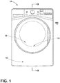
FIG. 1 is a front elevational view of a drying appliance that incorporates a system for performing an aspect of an after-care cycle on a load of laundry; -
FIG. 2 is a cross-sectional view of the appliance ofFIG. 1 ; -
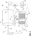
FIG. 3 is a schematic illustration of a heat pump drying appliance that can be used to perform various aspects of the after-care cycle; -
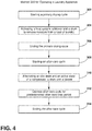
FIG. 4 is a schematic flow diagram illustrating a method for operating a drying appliance in performing a primary drying cycle and an after-care cycle; -
FIG. 5 is a schematic diagram illustrating operation of the various systems of the appliance over time during an after-care cycle; -
FIG. 6 is a schematic diagram illustrating operation of the various systems of the appliance over time during an after-care cycle; -
FIG. 7 is a schematic diagram illustrating operation of the various systems of the appliance over time during an after-care cycle; -
FIG. 8 is a schematic flow diagram illustrating a method for processing laundry after completion of a drying cycle using an after-care cycle; and -
FIG. 9 is a schematic flow diagram illustrating a method for processing laundry after completion of a drying cycle using an after-care cycle. - For purposes of description herein the terms "upper," "lower," "right," "left," "rear," "front," "vertical," "horizontal," and derivatives thereof shall relate to the device as oriented in
FIG. 1 . However, it is to be understood that the device may assume various alternative orientations and step sequences, except where expressly specified to the contrary. It is also to be understood that the specific devices and processes illustrated in the attached drawings, and described in the following specification are simply exemplary embodiments of the inventive concepts defined in the appended claims. Hence, specific dimensions and other physical characteristics relating to the embodiments disclosed herein are not to be considered as limiting, unless the claims expressly state otherwise. - As exemplified in
FIGS. 1-3 ,reference numeral 10 generally refers to a laundry appliance and typically a drying appliance that can perform variousprimary drying cycles 12 forprocessing laundry 14 within adrum 16 of theappliance 10. To assist in processing thelaundry 14 within thedrum 16, aheat pump system 18 is configured tocondition process air 20 that is moved through anairflow path 22. Theheat pump system 18 typically includes one ormore heat exchangers 24 in the form of anevaporator 26 and acondenser 28. Theevaporator 26 is configured to dehumidifyprocess air 20 that is delivered from thedrum 16. Theprocess air 20 delivered from thedrum 16 can includemoisture 30 and lint particles that are carried away from the load oflaundry 14 and are moved by theblower 32 through theairflow path 22 to theevaporator 26. Thecondenser 28 of theheat pump system 18 rejectsheat 34 from a surface of thecondenser 28 and delivers thisheat 34 into theprocess air 20. Theprocess air 20 is thereby heated and then delivered back to thedrum 16 for continuing the processing oflaundry 14. Theheat pump system 18 includes acompressor 40 that compresses a thermal exchange media, typically a refrigerant. Theheat pump system 18 delivers the thermal exchange media to theevaporator 26, through anexpansion device 42, to thecondenser 28, and then back to thecompressor 40. Theblower 32 of theappliance 10 deliversprocess air 20 through theairflow path 22 that includes the rotatingdrum 16 and thevarious heat exchangers 24 of theheat pump system 18. - During performance of a
particular drying cycle 12,moisture 30 is removed from the load oflaundry 14 and is moved to theheat exchangers 24 where the dehumidification performed by theevaporator 26 causes themoisture 30 to form condensate that is captured within adrain channel 50 of theappliance 10. Additionally, various otherresidual fluid 52, includingmoisture 30, water vapor and condensate in thedrain channel 50, is captured or otherwise deposited within portions of theairflow path 22 and can remain within theairflow path 22 after completion of thedrying cycle 12. - Referring now to
FIGS. 1-4 , amethod 300 is disclosed for operating aprimary drying cycle 12 and an after-care cycle 60. In operating theappliance 10, theprimary drying cycle 12 is activated (step 302). Thecompressor 40, thedrum 16 and theblower 32 are configured to operate to perform a primary drying cycle 12 (step 304). After thedrying cycle 12 is complete (step 306), the after-care cycle is initiated (step 308). The after-care cycle 60 can be performed through operation of thecompressor 40, thedrum 16 and theblower 32. This after-care cycle 60 is activated after completion of thedrying cycle 12. The after-care cycle 60 defines anactive state 62 where thecompressor 40 and thedrum 16 operate until theprocess air 20 leaving thedrum 16 has adrum temperature 64 that is approximately equal to a temperatureupper limit 66. When thedrum temperature 64 reaches this temperatureupper limit 66, thecompressor 40 is typically deactivated. The after-care cycle 60 also defines anidle state 68 where thecompressor 40 remains deactivated until thedrum temperature 64 of theprocess air 20 leaving thedrum 16 is proximate to a temperaturelower limit 70. The upper andlower limits drum temperature 64 correspond to a predeterminedtemperature range 72 for operating the after-care cycle 60. Theidle state 68 and theactive state 62 are alternated during performance of the after-care cycle 60 (step 310). This after-care cycle is typically operated until the end of a predetermined after-care time period 80 (step 312). The expiration of this predetermined after-care time period 80 will end the after-care cycle 60 (step 314). The after-care timer period can also be ended at an earlier time by a manual intervention by the user of theappliance 10. Additional details of the predeterminedtemperature range 72 will be described more fully below. - The after-
care cycle 60 is configured to be operated by thecompressor 40, thedrum 16 and theblower 32 for a length of time that corresponds to an after-care time period 80. Typically, the end of this after-care time period 80 will shut off theappliance 10 and end the after-care cycle 60 after a predetermined period of time. The after-care time period 80 can also end at the earlier of a manual termination of the after-care cycle 60 and the expiration of this predetermined after-care time period 80. According to various aspects of the device, this after-care time period 80 can be anywhere from four hours to nine hours and can typically be approximately six hours. Other time frames for the after-care time period 80 can also be used depending upon the design of the device and the needs of the user. - Referring now to
FIGS. 1-7 , during theidle state 68 of the after-care cycle 60, thedrum 16 and theblower 32 can define a tumblingcondition 90. During this tumblingcondition 90, thedrum 16 and theblower 32 are intermittently activated and deactivated. Theseintermittent activations 92 andintermittent deactivations 94 of thedrum 16 andblower 32 can serve to modify the positions of the various items oflaundry 14 within thedrum 16 so that during theactive state 62, theprocess air 20 moved through thedrum 16 can adequately move within and around the entire load oflaundry 14 during performance of the after-care cycle 60. In this manner, as illustrated inFIGS. 5-7 , the after-care cycle 60 can include various conditions that can be used withinseparate appliances 10 or used cooperatively within asingle appliance 10 depending upon the type oflaundry 14 that is being processed within thedrum 16. - As exemplified in
FIG. 5 , the after-care cycle 60 can be in the form of the tumblingcondition 90 where thedrum 16 andblower 32 operate cooperatively and intermittently to alternate periods ofintermittent activation 92 for processing and periods ofintermittent activation 92 for rest. By way of example, and not limitation, the tumblingcondition 90 can include a rest period ofintermittent deactivation 94, followed by a tumbling operation ofintermittent activation 92, where thedrum 16 andblower 32 are each activated for a certain amount of time and where thedrum 16 can rotate in a clockwise direction, counter-clockwise direction, or both. This tumbling operation can then followed by another period of rest. After the second period of rest, thedrum 16 and theblower 32 can be activated again, where thedrum 16 is rotated in the same direction or a different direction or different rotational pattern. These intermittent activations anddeactivations drum 16 andblower 32 can be carried on for the duration of the after-care time period 80. - As exemplified in
FIG. 6 , the after-care cycle 60 can include ahybrid heater 100 that is typically in the form of a resistive heater that can be activated during the after-care cycle 60. In this aspect of the device, the after-care cycle 60 can include a tumblingcondition 90 that is followed by an operation of thehybrid heater 100,drum 16 andblower 32 in theactive state 62 where each is activated for a particular period of time. Again, this pattern can be a sequentially repeatedoperation 102 of the after-care cycle 60 and can be repeated for the duration of the after-care time period 80. - An electrically resistive
hybrid heater 100 can be used as a heat source for elevating thedrum temperature 64 of theprocess air 20 to theupper limit 66 of thepredetermined temperature range 72. In various aspects of the device, nohybrid heater 100 is included and the primary heat source for modifying the temperature of theprocess air 20 is acondenser 28 for theheat pump system 18. Additionally, while anappliance 10 may include ahybrid heater 100, thehybrid heater 100 may be deactivated during performance of the after-care cycle 60. In such an embodiment, it is primarily thecondenser 28 of theheat pump system 18 that is used for an elevating temperature of theprocess air 20 to theupper limit 66 of thepredetermined temperature range 72. - In various aspects of the device, the electrically
resistive heater 100 can be used as part of a condenser system that utilizes an air-to-air heat exchanger 24. The air-to-air heat exchanger 24 includes theair flow path 22 that directsprocess air 20 through theheater 100. Theheated process air 20 is then directed into thedrum 16 to process thelaundry 14. The air-to-air heat exchanger 24 also includes a separate coolingair flow path 22 therein. This cooling air path uses a cooling fan to move cooler ambient air through the air-to-air heat exchanger 24 to lower the temperature of theprocess air 20 within theair flow path 22 of the air-to-air heat exchanger 24. The cooler ambient air is used to condense moisture present within theprocess air 20. The air-to-air heat exchanger 24 can be used to operate theprimary drying cycle 12 and also the after-care cycle 60. In this manner, the air-to-air heat exchanger and theheater 100 can be operated during the after-care cycle 60 to maintain thedrum temperature 64 of theprocess air 20 within thepredetermined temperature range 72. - As exemplified in
FIG. 7 , the after-care cycle 60 can include a tumblingcondition 90 that is followed by an operation of thecompressor 40 anddrum 16 in theactive state 62 whereheat 34 is provided by thecondenser 28 of theheat pump system 18 for increasing thedrum temperature 64 of theprocess air 20. In this aspect of the after-care cycle 60, thedrum 16 andblower 32 are cooperatively and intermittently activated and deactivated during the tumblingcondition 90. This tumblingcondition 90 is then followed by anactive state 62 of thecompressor 40 and drum 16 where thecondenser 28 providesheat 34 to theprocess air 20. Thisheated process air 20 is then delivered to thedrum 16 for processing thelaundry 14 during the after-care cycle 60. This pattern may also be repeated as a sequentially repeatedoperation 102 of the after-care cycle 60. - The pattern of
idle state 68 andactive state 62 can be the sequentially repeatedoperation 102 of the after-care cycle 60. Within this pattern of theidle state 68 andactive state 62, various sub-routines can also be performed. Such sub-routines can include performance of the tumblingcondition 90, patterns of drum rotation, or drum oscillation, varied operation of theblower 32 and/or thecompressor 40 and other similar sub-routines of the after-care cycle 60. - During the after-
care cycle 60,heat 34 from thehybrid heater 100 and/or thecondenser 28 providesheat 34 to theprocess air 20 and at least partially evaporates a portion of theresidual fluid 52 that is maintained within theairflow path 22 of theappliance 10. Thismoisture 30 added to theprocess air 20 forms moisture-laden process air 110 that enters thedrum 16. The moisture-laden process air 110 can assist in removing wrinkles and fresheninglaundry 14 being processed within thedrum 16 of theappliance 10. By addingmoisture 30 to theprocess air 20, theheated process air 20 is more able to retain theheat 34 that is given off by thecondenser 28 and/or thehybrid heater 100 of theappliance 10. The moisture-laden process air 110 is also efficient at releasing thisheat 34 into thelaundry 14, as will be described more fully below. - The inclusion of
heat 34 within theprocess air 20 and thelaundry 14 is critical to the performance of the after-care cycle 60. After the completion of theprimary drying cycle 12, certain amounts ofmoisture 30 typically remain within the load oflaundry 14 contained within thedrum 16. Thismoisture 30 in thelaundry 14 may contain various bacteria, microbes and other contaminants that may generate odor in the form of mildew, and other foul-smelling contaminants. Performance testing of the after-care cycle 60 has shown that populations of bacteria and other microbes can be diminished or held in check through the application of a certain amount ofheat 34 within theprocess air 20 as it moves through thedrum 16. Theheated process air 20 having adrum temperature 64 that is within the particularpredetermined temperature range 72 has been shown to be effective at killing at least a portion of the bacteria population and other microbe populations within thelaundry 14 contained within thedrum 16. - A
lower limit 70 of thispredetermined temperature range 72 has been found to approximately 35°C. At this temperature, the growth of bacteria within thelaundry 14 can be mitigated and the amount of bacteria may be decreased when theprocess air 20 is heated to thislower limit 70 of thepredetermined temperature range 72. Thepredetermined temperature range 72, for purposes of controlling bacteria population, may have no particularupper limit 66 as greater amounts ofheat 34 will typically serve to kill more bacteria within thedrum 16. However, where theprocess air 20 is heated to a temperature that is in excess of anupper limit 66 of thepredetermined temperature range 72, theprocess air 20 heated to these excessive temperatures may cause damage to the clothing contained within adrum 16. - Performance testing of various aspects of the after-
care cycle 60 have shown that an effectiveupper limit 66 of thepredetermined temperature range 72 can be approximately 42°C. It should be understood that thisupper limit 66 of thepredetermined temperature range 72 can vary depending upon the type oflaundry 14 being processed within thedrum 16. Delicate fabrics may have a lowerupper limit 66 in the form of alower drum temperature 64 within thispredetermined temperature range 72. Alternatively, more sturdy fabrics such as cotton may have a higherupper limit 66 in the form of ahigher drum temperature 64 for this correspondingpredetermined temperature range 72. - Using the after-
care cycle 60 described herein, theprocess air 20 can be maintained within thepredetermined temperature range 72 for processinglaundry 14 during the after-care cycle 60. Theprocess air 20 having adrum temperature 64 within thispredetermined temperature range 72 has been shown to be effective at killing bacteria or at least preventing the growth of bacteria populations that can generate odor withindamp laundry 14. Accordingly, during the performance of the after-care cycle 60 for the after-care time period 80, the load oflaundry 14 can remain fresh smelling as a result of theprocess air 20 having adrum temperature 64 within thepredetermined temperature range 72 for killing sufficient amounts of bacteria and preventing the growth of bacteria within a load oflaundry 14. By controlling bacteria populations and, in turn, odors, the use of additional fragrancing products can be reduced. Additionally, the length of the after-care cycle 60 can allow a user of theappliance 10 to leave a load oflaundry 14 within thedrum 16 for an extended period of time without causing unwanted odors within thelaundry 14. - Typically, the after-
care cycle 60 will include theprocess air 20 being heated using thecondenser 28 of theheat pump system 18. Additionally, by using thecondenser 28, the amount ofheat 34 delivered to thedrum 16 via theprocess air 20 can be maintained within thepredetermined temperature range 72 to effectively manage the population of bacteria within thelaundry 14 and also to prevent substantial damage to thelaundry 14 during operation of the after-care cycle 60. - Referring now to
FIGS. 1-8 , having discussed the various aspects of the after-care cycle 60 for thelaundry appliance 10, amethod 400 is disclosed for processinglaundry 14 after completion of aprimary drying cycle 12 using aspects of the after-care cycle 60. According to themethod 400, a dryingcycle 12 is performed to processlaundry 14 within thedrum 16 of the appliance 10 (step 402). After the dryingcycle 12 is completed,residual fluid 52, typically in the form of water, is disposed within theairflow path 22 of theappliance 10, as a result of the performance of the drying cycle 12 (step 404). This residual fluid 52 can be within theductwork 120 of theairflow path 22, within theheat exchange cavity 122 that houses thecondenser 28 andevaporator 26, within the drum itself, within thelaundry 14 located within thedrum 16, and also within adrain channel 50 that is typically positioned below theevaporator 26 of theheat pump system 18. Theresidual fluid 52 within these portions of theappliance 10 can be used to addmoisture 30 and humidity to theprocess air 20 during the after-care cycle 60. - According to the
method 400, after theprimary drying cycle 12 is complete, the after-care cycle 60 can be initiated (step 406). In this manner, theheat pump system 18 and theblower 32 are activated to deliverprocess air 20 and at least a portion of thisresidual fluid 52 to thedrum 16. Thisresidual fluid 52 is delivered asmoisture 30 from theprocess air 20 that can allow greater amounts ofheat 34 to be delivered to thedrum 16. During performance of the after-care cycle 60, thedrum temperature 64 of theprocess air 20 is maintained at thepredetermined temperature range 72 during performance of the after-care cycle 60 (step 408). - When the
blower 32 is activated, it is typical that themotor 130 for theblower 32 can be thesame motor 130 that operates thedrum 16 by rotating thedrum 16 about arotational axis 132. Accordingly, when theblower 32 is activated, rotation of thedrum 16 is also activated for processing thelaundry 14 during the after-care cycle 60. Thedrum 16 and theblower 32 may also be operated using separate anddedicated motors 130.Separate motors 130 may be incorporated for thedrum 16 and theblower 32 where thedrum 16 is configured for bi-directional rotation in clockwise and counterclockwise directions. - As exemplified in
FIGS. 1-8 , at the end of theprimary drying cycle 12, thedrum temperature 64 of the air andlaundry 14 within thedrum 16 may be at a level within or above thepredetermined temperature range 72. In such a condition, activation of the after-care cycle 60 may be delayed. Accordingly, thestep 406 of initiating the after-care cycle 60 can include a condition where theheat pump system 18 is placed in theactive state 62 when thedrum temperature 64 reaches thelower limit 70 of thepredetermined temperature range 72. Similarly, theheat pump system 18, during the after-care cycle 60, can be deactivated, or placed in theidle state 68, when thedrum temperature 64 of theprocess air 20 reaches theupper limit 66 of thepredetermined temperature range 72. By maintaining thedrum temperature 64 within thepredetermined temperature range 72, the population of bacteria within thelaundry 14 can be controlled to mitigate the presence of odor emanating from thelaundry 14 over the course of the after-care cycle 60 without substantially causing damage to thelaundry 14. - To assist in maintaining the
drum temperature 64 within thepredetermined temperature range 72, thedrum temperature 64 can be measured by atemperature probe 140 that is disposed within theairflow path 22. Typically, the probe can be disposed within theairflow path 22 in a position downstream of thedrum 16. It should be understood that the positioning of thetemperature probe 140 can also be within thedrum 16 or at a position upstream of thedrum 16, depending upon the design of theappliance 10. - Referring once again to
FIGS. 1-8 , when the after-care cycle 60 is activated, operation of thedrum 16 can be in either a clockwise or counterclockwise direction about therotational axis 132 of thedrum 16. Additionally, during the various tumblingconditions 90 of the after-care cycle 60, rotation of thedrum 16 can be alternated or oscillated between a clockwise and counter-clockwise rotation. This two-way rotation of thedrum 16 can achieve greater mixing and mingling of the items oflaundry 14 within thedrum 16. Accordingly, theprocess air 20 that has been heated to thepredetermined temperature range 72 to be more effective at controlling the bacteria population within thedrum 16 and thelaundry 14 contained therein. - During the
idle state 68 of the after-care cycle 60, when thecompressor 40 is typically deactivated, the after-care cycle 60 can include an intermediate tumblingcondition 90 that is performed after thedrum temperature 64 reaches theupper limit 66 and before thedrum temperature 64 reaches thelower limit 70 of thepredetermined temperature range 72. As discussed above, this tumblingcondition 90 serves to mingle and change positions of the various items oflaundry 14 contained within thedrum 16. By changing the position of thelaundry 14 within thedrum 16, theheated process air 20 may be spread more evenly throughout the entire load oflaundry 14, over the performance of the after-care cycle 60. - Referring now to
FIGS. 1-7 and9 , themethod 500 is disclosed for processing a load oflaundry 14 after completion of theprimary drying cycle 12 using an after-care cycle 60. According to themethod 500, a dryingcycle 12 is completed that processeslaundry 14 within the rotating drum 16 (step 502). Performance of the dryingcycle 12 results inresidual fluid 52 being disposed within at least theairflow path 22 that includes thedrum 16. After completion of the dryingcycle 12, the after-care cycle 60 is activated (step 504). The after-care cycle 60 is configured to operate for a predetermined after-care time period 80. As discussed previously, this after-care time period 80 can vary and is typically operated for an extended period of time, as discussed herein. - During performance of the after-
care cycle 60, thedrum temperature 64 of theprocess air 20 within thedrum 16 is maintained at apredetermined temperature range 72 during performance of the after-care cycle 60 (step 506). To assist in maintaining thedrum temperature 64 of theprocess air 20, theheat pump system 18 is activated, or placed in theactive state 62, when thedrum temperature 64 of theprocess air 20 reaches thelower limit 70 of the predetermined temperature range 72 (step 508). When theheat pump system 18 is activated, thecondenser 28 rejects heat 34 into theprocess air 20 and allows for evaporation of theresidual fluid 52 within theprocess air 20 in the form ofmoisture 30 that is delivered to thedrum 16. Theheat pump system 18 can then be deactivated or placed in theidle state 68 when thedrum temperature 64 of theprocess air 20 reaches theupper limit 66 of the predetermined temperature range 72 (step 510). The completion ordeactivation 94 of the after-care cycle 60 can take place at the earlier of the manual termination by the user deactivating the appliance 10 (step 512). Alternatively, deactivation 94 of the after-care cycle 60 can take place at the expiration of the predetermined after-care time period 80 as discussed above. - While
residual fluid 52 is used in various aspects of the after-care cycle 60, certain configurations of the after-care cycle 60 may be performed without the use ofresidual fluid 52. In certain instances, aprimary drying cycle 12 may result in little to noresidual fluid 52 being deposited in theair flow path 22. Various aspects of theappliance 10 may remove substantially all of theresidual fluid 52 from theair flow path 22 before the after-care cycle 60 is activated. Where little to noresidual fluid 52 is included in theair flow path 22 for use in the after-care cycle 60,heat 34 can used without the addition of theresidual fluid 52 for operating the after-care cycle 60. Water can also be added to theair flow path 22 or to thedrum 16 during performance of the after-care cycle 60. As discussed previously, theheat 34 is used to control the growth of bacterial populations within thelaundry 14 being processed within thedrum 16. - Referring again to
FIGS. 1-4 , theheat pump system 18 can include acompressor cooling fan 150 that blows coolingair 152 across the surface of thecompressor 40. According to various aspects of the device, thecompressor cooling fan 150 typically remains deactivated when the after-care cycle 60 is in theactive state 62. Accordingly, during theactive state 62 of the after-care cycle 60, thecompressor 40 and themotor 130 for theblower 32 of thedrum 16 are switched on. At this time, thecompressor cooling fan 150 is switched off. As discussed above, theactive state 62 in the after-care cycle 60 is maintained until thedrum temperature 64 of theprocess air 20 reaches theupper limit 66 of thepredetermined temperature range 72. - The amount of time that the after-
care cycle 60 is in theactive state 62 can vary depending upon various conditions within and around theappliance 10. Accordingly, the type oflaundry 14 being processed within thedrum 16, theambient temperature 160 of the air around theappliance 10, the moisture content of the articles of clothing within the load, and other factors can increase or decrease the amount of time it takes for thecondenser 28 of theheat pump system 18 to heat theprocess air 20 from thelower limit 70 of thepredetermined temperature range 72 to theupper limit 66 of thepredetermined temperature range 72. Similarly, these factors can bear on the amount of time it takes for the ambient conditions in and around theappliance 10 to allow thedrum temperature 64 of theprocess air 20 and the temperature of the air within thedrum 16 to decrease from theupper limit 66 from theupper temperature range 72 and back down to thelower limit 70 of thepredetermined temperature range 72. Accordingly, the amount of time that the after-care cycle 60 defines the active andidle states cycles 12 in theparticular appliance 10 and can also vary in a single performance of the after-care cycle 60. Because the conditions within and around theappliance 10 change over the course of the after-care cycle 60, the factors that bear on the amount of time that it takes for thedrum 16 temperature of theprocess air 20 to fluctuate between the upper andlower limits care cycle 60. - The various aspects of the device disclosed herein can be used within the
various appliances 10. Theseappliances 10 can include, but are not limited to, drying appliances, combination washing/drying appliances, and other similar laundry-processing appliances.
Claims (15)
- A method for processing laundry after completion of a drying cycle (12), the method comprising steps of:maintaining residual fluid (52) within an airflow path (22) of the appliance (10), wherein the residual fluid (52) results from a primary drying cycle (12);activating a heat pump system (18) and a blower (32) to deliver the residual fluid (52) to the drum (16); andmaintaining a drum temperature (64) within the drum (16) at a predetermined temperature range (72) during performance of the after-care cycle (60).
- The method of claim 1, wherein the step of activating the heat pump system (18) takes place at least when the drum temperature (64) reaches a lower limit of the predetermined temperature range (72).
- The method of claim 2, wherein after the heat pump system (18) is activated, the heat pump system (18) is deactivated when the drum temperature (64) reaches an upper limit of the predetermined temperature range (72).
- The method of claim 3, wherein the drum temperature (64) is measured by a temperature probe (140) disposed within the airflow path (22) and downstream of the drum (16).
- The method of claim 4, wherein the temperature probe (140) is disposed within the airflow path (22) and downstream of the drum (16).
- The method of any one or more of claims 1-5, wherein the step of activating the blower (32) includes activating a rotation of the drum (16) in at least one direction.
- The method of any one or more of claims 1-6, wherein the predetermined temperature range (72) is from approximately 35 degrees Celsius to approximately 42 degrees Celsius.
- The method of any one or more of claims 1-7, wherein the residual fluid (52) is at least partially contained within a drain channel (50) disposed beneath a heat exchanger (24) of the heat pump system (18).
- The method of any one or more of claims 1-8, wherein the heat pump system (18) includes a compressor cooling fan (150) and the compressor cooling fan (150) remains deactivated while the drum temperature (64) is within the predetermined temperature range (72).
- The method of any one or more of claims 1-9, wherein after completion of the primary drying cycle (12), the heat pump system (18) and the blower (32) are configured to be activated and deactivated in a repeating operation that continues for a predetermined after-care time period (80).
- The method of claim 10, wherein the repeating operation is configured to continue until the earlier of a manual termination of the sequentially repeated operation and an expiration of the predetermined after-care time period (80).
- The method of claim 11, wherein the predetermined after-care time period (80) is approximately 6 hours.
- The method of any one or more of claims 6-12, wherein the rotation of the drum (16) during the after-care cycle (60) is defined by a bi-directional rotation in clockwise and counterclockwise directions.
- The method of any one or more of claims 6-12, wherein a single motor (130) is configured to activate the blower (32) and activate the rotation of the drum (16).
- The method of any one or more of claims 1-14, wherein the predetermined temperature range (72) is configured to control microbe populations within the drum (16) during the after-care cycle (60).
Applications Claiming Priority (1)
| Application Number | Priority Date | Filing Date | Title |
|---|---|---|---|
| US15/726,965 US10480116B2 (en) | 2017-10-06 | 2017-10-06 | Drying appliance that performs after-care cycle on a load of laundry after completion of a primary drying cycle and method for performing the after-care cycle |
Publications (2)
| Publication Number | Publication Date |
|---|---|
| EP3467185A1 true EP3467185A1 (en) | 2019-04-10 |
| EP3467185B1 EP3467185B1 (en) | 2020-06-10 |
Family
ID=63787811
Family Applications (1)
| Application Number | Title | Priority Date | Filing Date |
|---|---|---|---|
| EP18198849.4A Active EP3467185B1 (en) | 2017-10-06 | 2018-10-05 | Drying appliance that performs after-care cycle on a load of laundry after completion of a primary drying cycle and method for performing the after-care cycle |
Country Status (2)
| Country | Link |
|---|---|
| US (1) | US10480116B2 (en) |
| EP (1) | EP3467185B1 (en) |
Families Citing this family (3)
| Publication number | Priority date | Publication date | Assignee | Title |
|---|---|---|---|---|
| DE102016000226A1 (en) * | 2016-01-14 | 2017-07-20 | Herbert Kannegiesser Gmbh | Device for mangling laundry |
| CN112080914B (en) * | 2020-08-18 | 2023-06-20 | 广州视源电子科技股份有限公司 | Laundry care machine control method, device, medium and laundry care machine |
| US20240125040A1 (en) * | 2022-10-13 | 2024-04-18 | Haier Us Appliance Solutions, Inc. | Method for scheduling and executing a warmup cycle in a dryer appliance |
Citations (3)
| Publication number | Priority date | Publication date | Assignee | Title |
|---|---|---|---|---|
| EP2466001A1 (en) * | 2010-12-20 | 2012-06-20 | Indesit Company S.p.A. | A machine for drying laundry for domestic use |
| EP2765235A1 (en) * | 2013-02-06 | 2014-08-13 | Panasonic Corporation | Laundry dryer |
| EP3173009A1 (en) * | 2015-11-24 | 2017-05-31 | BSH Hausgeräte GmbH | Household appliance with a heat pump and method for operating a household appliance |
Family Cites Families (20)
| Publication number | Priority date | Publication date | Assignee | Title |
|---|---|---|---|---|
| US4621438A (en) * | 1980-12-04 | 1986-11-11 | Donald M. Thompson | Energy efficient clothes dryer |
| DE4306217B4 (en) * | 1993-02-27 | 2004-04-22 | AEG Hausgeräte GmbH | Program-controlled tumble dryer with a heat pump circuit |
| US5369892A (en) * | 1993-06-04 | 1994-12-06 | Dhaemers; Gregory L. | Armoire |
| EP1564325B1 (en) | 2004-02-10 | 2018-04-11 | Electrolux Home Products Corporation N.V. | Improved clothes drying machine with clothes smoothing ability |
| KR101137335B1 (en) | 2005-08-25 | 2012-04-19 | 엘지전자 주식회사 | operating method for laundry machine |
| US9663894B2 (en) | 2005-11-10 | 2017-05-30 | Lg Electronics Inc. | Steam generator and laundry dryer having the same and controlling method thereof |
| EP1852539B1 (en) | 2006-05-02 | 2010-07-14 | Electrolux Home Products Corporation N.V. | Drying program with anti-crease phase and dryer |
| US8104191B2 (en) * | 2008-07-31 | 2012-01-31 | Electrolux Home Products, Inc. | Laundry dryer providing moisture application during tumbling and reduced airflow |
| EP2163682B1 (en) * | 2008-09-12 | 2013-01-09 | Electrolux Home Products Corporation N.V. | Home laundry drier |
| EP2390397A1 (en) * | 2010-05-25 | 2011-11-30 | Electrolux Home Products Corporation N.V. | A method for operating a washing cycle and a subsequent drying cycle in a laundry washer-dryer |
| EP2441880B1 (en) * | 2010-10-15 | 2013-08-21 | Whirlpool Corporation | Method for drying clothes in a drier and a moisture estimation control to obtain an automatic cycle termination |
| US9631315B2 (en) * | 2011-03-29 | 2017-04-25 | Lg Electronics Inc. | Controlling method for clothes dryer |
| US9834882B2 (en) * | 2011-07-07 | 2017-12-05 | Haier Us Appliance Solutions, Inc. | Device and method for heat pump based clothes dryer |
| EP2623662B1 (en) | 2012-02-06 | 2018-04-04 | LG Electronics Inc. | Laundry machine and control method thereof |
| EP2918722B1 (en) | 2014-03-14 | 2021-01-20 | Whirlpool Corporation | Method for treating clothes in a dryer |
| CN106480681B (en) * | 2015-08-31 | 2019-08-27 | 青岛海尔滚筒洗衣机有限公司 | A direct exhaust heat pump clothes dryer |
| PL3162952T3 (en) * | 2015-10-26 | 2019-09-30 | Electrolux Appliances Aktiebolag | Laundry drying appliance with capacitive laundry drying degree sensing function |
| US10662574B2 (en) * | 2017-02-27 | 2020-05-26 | Whirlpool Corporation | Self cleaning heater exchanger plate |
| US10480117B2 (en) * | 2017-02-27 | 2019-11-19 | Whirlpool Corporation | Self cleaning sump cover |
| US10704189B2 (en) * | 2017-08-25 | 2020-07-07 | Whirlpool Corporation | Laundry appliance having an ultrasonic drying mechanism |
-
2017
- 2017-10-06 US US15/726,965 patent/US10480116B2/en active Active
-
2018
- 2018-10-05 EP EP18198849.4A patent/EP3467185B1/en active Active
Patent Citations (3)
| Publication number | Priority date | Publication date | Assignee | Title |
|---|---|---|---|---|
| EP2466001A1 (en) * | 2010-12-20 | 2012-06-20 | Indesit Company S.p.A. | A machine for drying laundry for domestic use |
| EP2765235A1 (en) * | 2013-02-06 | 2014-08-13 | Panasonic Corporation | Laundry dryer |
| EP3173009A1 (en) * | 2015-11-24 | 2017-05-31 | BSH Hausgeräte GmbH | Household appliance with a heat pump and method for operating a household appliance |
Also Published As
| Publication number | Publication date |
|---|---|
| EP3467185B1 (en) | 2020-06-10 |
| US10480116B2 (en) | 2019-11-19 |
| US20190106831A1 (en) | 2019-04-11 |
Similar Documents
| Publication | Publication Date | Title |
|---|---|---|
| US12338571B2 (en) | Method of controlling laundry treating apparatus | |
| RU2413805C2 (en) | Drying machine and method to control this machine | |
| EP3467185B1 (en) | Drying appliance that performs after-care cycle on a load of laundry after completion of a primary drying cycle and method for performing the after-care cycle | |
| CN109208290B (en) | Method for operating a laundry dryer and laundry dryer | |
| KR20160111685A (en) | Fabric treating apparatus and Controlling method therefor | |
| KR20090105084A (en) | Control Method of Clothing Processing Equipment | |
| KR102483851B1 (en) | Apparatus for laundry treatment and method of controlling the same | |
| KR20090014054A (en) | Control Method of Clothing Processing Equipment | |
| CN113279226B (en) | Control method of clothes treatment device | |
| CN112064306B (en) | Clothes care method, clothes care machine and computer readable storage medium | |
| WO2010109794A1 (en) | Heater-dryer and control method for heater-dryer | |
| CN111139622A (en) | Control method for laundry treatment apparatus and laundry treatment apparatus | |
| US20230414062A1 (en) | Shoe care apparatus and control method therefor | |
| KR20040009401A (en) | Cloth managing device | |
| JP2013128541A (en) | Clothing drying machine | |
| KR102032910B1 (en) | Clothes dry device | |
| JP5433969B2 (en) | Deodorization device | |
| JP2013153934A (en) | Clothing dryer | |
| WO2015063016A1 (en) | A laundry dryer with increased ventilating effectiveness | |
| US20250019892A1 (en) | Method and apparatus for carrying out a cleaning process for a cleaning appliance, and cleaning appliance | |
| CN110926199B (en) | Control method of drying device, drying device and controller | |
| JP7821411B2 (en) | clothes dryer | |
| KR102634419B1 (en) | Clothes dryer with sliding-type pull-out structure | |
| WO2020057839A1 (en) | A laundry dryer | |
| JP4516704B2 (en) | Superheated steam drying method and apparatus |
Legal Events
| Date | Code | Title | Description |
|---|---|---|---|
| PUAI | Public reference made under article 153(3) epc to a published international application that has entered the european phase |
Free format text: ORIGINAL CODE: 0009012 |
|
| STAA | Information on the status of an ep patent application or granted ep patent |
Free format text: STATUS: THE APPLICATION HAS BEEN PUBLISHED |
|
| AK | Designated contracting states |
Kind code of ref document: A1 Designated state(s): AL AT BE BG CH CY CZ DE DK EE ES FI FR GB GR HR HU IE IS IT LI LT LU LV MC MK MT NL NO PL PT RO RS SE SI SK SM TR |
|
| AX | Request for extension of the european patent |
Extension state: BA ME |
|
| STAA | Information on the status of an ep patent application or granted ep patent |
Free format text: STATUS: REQUEST FOR EXAMINATION WAS MADE |
|
| 17P | Request for examination filed |
Effective date: 20191002 |
|
| RBV | Designated contracting states (corrected) |
Designated state(s): AL AT BE BG CH CY CZ DE DK EE ES FI FR GB GR HR HU IE IS IT LI LT LU LV MC MK MT NL NO PL PT RO RS SE SI SK SM TR |
|
| RIC1 | Information provided on ipc code assigned before grant |
Ipc: D06F 58/20 20060101AFI20200116BHEP |
|
| GRAP | Despatch of communication of intention to grant a patent |
Free format text: ORIGINAL CODE: EPIDOSNIGR1 |
|
| STAA | Information on the status of an ep patent application or granted ep patent |
Free format text: STATUS: GRANT OF PATENT IS INTENDED |
|
| INTG | Intention to grant announced |
Effective date: 20200306 |
|
| GRAS | Grant fee paid |
Free format text: ORIGINAL CODE: EPIDOSNIGR3 |
|
| GRAA | (expected) grant |
Free format text: ORIGINAL CODE: 0009210 |
|
| STAA | Information on the status of an ep patent application or granted ep patent |
Free format text: STATUS: THE PATENT HAS BEEN GRANTED |
|
| AK | Designated contracting states |
Kind code of ref document: B1 Designated state(s): AL AT BE BG CH CY CZ DE DK EE ES FI FR GB GR HR HU IE IS IT LI LT LU LV MC MK MT NL NO PL PT RO RS SE SI SK SM TR |
|
| REG | Reference to a national code |
Ref country code: GB Ref legal event code: FG4D |
|
| REG | Reference to a national code |
Ref country code: CH Ref legal event code: EP Ref country code: AT Ref legal event code: REF Ref document number: 1279280 Country of ref document: AT Kind code of ref document: T Effective date: 20200615 |
|
| REG | Reference to a national code |
Ref country code: DE Ref legal event code: R096 Ref document number: 602018005190 Country of ref document: DE |
|
| REG | Reference to a national code |
Ref country code: IE Ref legal event code: FG4D |
|
| REG | Reference to a national code |
Ref country code: LT Ref legal event code: MG4D |
|
| PG25 | Lapsed in a contracting state [announced via postgrant information from national office to epo] |
Ref country code: NO Free format text: LAPSE BECAUSE OF FAILURE TO SUBMIT A TRANSLATION OF THE DESCRIPTION OR TO PAY THE FEE WITHIN THE PRESCRIBED TIME-LIMIT Effective date: 20200910 Ref country code: GR Free format text: LAPSE BECAUSE OF FAILURE TO SUBMIT A TRANSLATION OF THE DESCRIPTION OR TO PAY THE FEE WITHIN THE PRESCRIBED TIME-LIMIT Effective date: 20200911 Ref country code: LT Free format text: LAPSE BECAUSE OF FAILURE TO SUBMIT A TRANSLATION OF THE DESCRIPTION OR TO PAY THE FEE WITHIN THE PRESCRIBED TIME-LIMIT Effective date: 20200610 Ref country code: FI Free format text: LAPSE BECAUSE OF FAILURE TO SUBMIT A TRANSLATION OF THE DESCRIPTION OR TO PAY THE FEE WITHIN THE PRESCRIBED TIME-LIMIT Effective date: 20200610 Ref country code: SE Free format text: LAPSE BECAUSE OF FAILURE TO SUBMIT A TRANSLATION OF THE DESCRIPTION OR TO PAY THE FEE WITHIN THE PRESCRIBED TIME-LIMIT Effective date: 20200610 |
|
| REG | Reference to a national code |
Ref country code: NL Ref legal event code: MP Effective date: 20200610 |
|
| PG25 | Lapsed in a contracting state [announced via postgrant information from national office to epo] |
Ref country code: RS Free format text: LAPSE BECAUSE OF FAILURE TO SUBMIT A TRANSLATION OF THE DESCRIPTION OR TO PAY THE FEE WITHIN THE PRESCRIBED TIME-LIMIT Effective date: 20200610 Ref country code: BG Free format text: LAPSE BECAUSE OF FAILURE TO SUBMIT A TRANSLATION OF THE DESCRIPTION OR TO PAY THE FEE WITHIN THE PRESCRIBED TIME-LIMIT Effective date: 20200910 Ref country code: LV Free format text: LAPSE BECAUSE OF FAILURE TO SUBMIT A TRANSLATION OF THE DESCRIPTION OR TO PAY THE FEE WITHIN THE PRESCRIBED TIME-LIMIT Effective date: 20200610 Ref country code: HR Free format text: LAPSE BECAUSE OF FAILURE TO SUBMIT A TRANSLATION OF THE DESCRIPTION OR TO PAY THE FEE WITHIN THE PRESCRIBED TIME-LIMIT Effective date: 20200610 |
|
| REG | Reference to a national code |
Ref country code: AT Ref legal event code: MK05 Ref document number: 1279280 Country of ref document: AT Kind code of ref document: T Effective date: 20200610 |
|
| PG25 | Lapsed in a contracting state [announced via postgrant information from national office to epo] |
Ref country code: AL Free format text: LAPSE BECAUSE OF FAILURE TO SUBMIT A TRANSLATION OF THE DESCRIPTION OR TO PAY THE FEE WITHIN THE PRESCRIBED TIME-LIMIT Effective date: 20200610 Ref country code: NL Free format text: LAPSE BECAUSE OF FAILURE TO SUBMIT A TRANSLATION OF THE DESCRIPTION OR TO PAY THE FEE WITHIN THE PRESCRIBED TIME-LIMIT Effective date: 20200610 |
|
| PG25 | Lapsed in a contracting state [announced via postgrant information from national office to epo] |
Ref country code: PT Free format text: LAPSE BECAUSE OF FAILURE TO SUBMIT A TRANSLATION OF THE DESCRIPTION OR TO PAY THE FEE WITHIN THE PRESCRIBED TIME-LIMIT Effective date: 20201012 Ref country code: ES Free format text: LAPSE BECAUSE OF FAILURE TO SUBMIT A TRANSLATION OF THE DESCRIPTION OR TO PAY THE FEE WITHIN THE PRESCRIBED TIME-LIMIT Effective date: 20200610 Ref country code: CZ Free format text: LAPSE BECAUSE OF FAILURE TO SUBMIT A TRANSLATION OF THE DESCRIPTION OR TO PAY THE FEE WITHIN THE PRESCRIBED TIME-LIMIT Effective date: 20200610 Ref country code: AT Free format text: LAPSE BECAUSE OF FAILURE TO SUBMIT A TRANSLATION OF THE DESCRIPTION OR TO PAY THE FEE WITHIN THE PRESCRIBED TIME-LIMIT Effective date: 20200610 Ref country code: RO Free format text: LAPSE BECAUSE OF FAILURE TO SUBMIT A TRANSLATION OF THE DESCRIPTION OR TO PAY THE FEE WITHIN THE PRESCRIBED TIME-LIMIT Effective date: 20200610 Ref country code: EE Free format text: LAPSE BECAUSE OF FAILURE TO SUBMIT A TRANSLATION OF THE DESCRIPTION OR TO PAY THE FEE WITHIN THE PRESCRIBED TIME-LIMIT Effective date: 20200610 Ref country code: SM Free format text: LAPSE BECAUSE OF FAILURE TO SUBMIT A TRANSLATION OF THE DESCRIPTION OR TO PAY THE FEE WITHIN THE PRESCRIBED TIME-LIMIT Effective date: 20200610 |
|
| PG25 | Lapsed in a contracting state [announced via postgrant information from national office to epo] |
Ref country code: SK Free format text: LAPSE BECAUSE OF FAILURE TO SUBMIT A TRANSLATION OF THE DESCRIPTION OR TO PAY THE FEE WITHIN THE PRESCRIBED TIME-LIMIT Effective date: 20200610 Ref country code: PL Free format text: LAPSE BECAUSE OF FAILURE TO SUBMIT A TRANSLATION OF THE DESCRIPTION OR TO PAY THE FEE WITHIN THE PRESCRIBED TIME-LIMIT Effective date: 20200610 Ref country code: IS Free format text: LAPSE BECAUSE OF FAILURE TO SUBMIT A TRANSLATION OF THE DESCRIPTION OR TO PAY THE FEE WITHIN THE PRESCRIBED TIME-LIMIT Effective date: 20201010 |
|
| REG | Reference to a national code |
Ref country code: DE Ref legal event code: R097 Ref document number: 602018005190 Country of ref document: DE |
|
| PLBE | No opposition filed within time limit |
Free format text: ORIGINAL CODE: 0009261 |
|
| STAA | Information on the status of an ep patent application or granted ep patent |
Free format text: STATUS: NO OPPOSITION FILED WITHIN TIME LIMIT |
|
| PG25 | Lapsed in a contracting state [announced via postgrant information from national office to epo] |
Ref country code: DK Free format text: LAPSE BECAUSE OF FAILURE TO SUBMIT A TRANSLATION OF THE DESCRIPTION OR TO PAY THE FEE WITHIN THE PRESCRIBED TIME-LIMIT Effective date: 20200610 |
|
| 26N | No opposition filed |
Effective date: 20210311 |
|
| PG25 | Lapsed in a contracting state [announced via postgrant information from national office to epo] |
Ref country code: SI Free format text: LAPSE BECAUSE OF FAILURE TO SUBMIT A TRANSLATION OF THE DESCRIPTION OR TO PAY THE FEE WITHIN THE PRESCRIBED TIME-LIMIT Effective date: 20200610 |
|
| PG25 | Lapsed in a contracting state [announced via postgrant information from national office to epo] |
Ref country code: LU Free format text: LAPSE BECAUSE OF NON-PAYMENT OF DUE FEES Effective date: 20201005 Ref country code: MC Free format text: LAPSE BECAUSE OF FAILURE TO SUBMIT A TRANSLATION OF THE DESCRIPTION OR TO PAY THE FEE WITHIN THE PRESCRIBED TIME-LIMIT Effective date: 20200610 |
|
| REG | Reference to a national code |
Ref country code: BE Ref legal event code: MM Effective date: 20201031 |
|
| PG25 | Lapsed in a contracting state [announced via postgrant information from national office to epo] |
Ref country code: BE Free format text: LAPSE BECAUSE OF NON-PAYMENT OF DUE FEES Effective date: 20201031 |
|
| PG25 | Lapsed in a contracting state [announced via postgrant information from national office to epo] |
Ref country code: IE Free format text: LAPSE BECAUSE OF NON-PAYMENT OF DUE FEES Effective date: 20201005 |
|
| REG | Reference to a national code |
Ref country code: CH Ref legal event code: PL |
|
| PG25 | Lapsed in a contracting state [announced via postgrant information from national office to epo] |
Ref country code: TR Free format text: LAPSE BECAUSE OF FAILURE TO SUBMIT A TRANSLATION OF THE DESCRIPTION OR TO PAY THE FEE WITHIN THE PRESCRIBED TIME-LIMIT Effective date: 20200610 Ref country code: MT Free format text: LAPSE BECAUSE OF FAILURE TO SUBMIT A TRANSLATION OF THE DESCRIPTION OR TO PAY THE FEE WITHIN THE PRESCRIBED TIME-LIMIT Effective date: 20200610 Ref country code: CY Free format text: LAPSE BECAUSE OF FAILURE TO SUBMIT A TRANSLATION OF THE DESCRIPTION OR TO PAY THE FEE WITHIN THE PRESCRIBED TIME-LIMIT Effective date: 20200610 |
|
| PG25 | Lapsed in a contracting state [announced via postgrant information from national office to epo] |
Ref country code: MK Free format text: LAPSE BECAUSE OF FAILURE TO SUBMIT A TRANSLATION OF THE DESCRIPTION OR TO PAY THE FEE WITHIN THE PRESCRIBED TIME-LIMIT Effective date: 20200610 |
|
| PG25 | Lapsed in a contracting state [announced via postgrant information from national office to epo] |
Ref country code: LI Free format text: LAPSE BECAUSE OF NON-PAYMENT OF DUE FEES Effective date: 20211031 Ref country code: CH Free format text: LAPSE BECAUSE OF NON-PAYMENT OF DUE FEES Effective date: 20211031 |
|
| P01 | Opt-out of the competence of the unified patent court (upc) registered |
Effective date: 20230522 |
|
| PGFP | Annual fee paid to national office [announced via postgrant information from national office to epo] |
Ref country code: DE Payment date: 20241031 Year of fee payment: 7 |
|
| PGFP | Annual fee paid to national office [announced via postgrant information from national office to epo] |
Ref country code: GB Payment date: 20241031 Year of fee payment: 7 |
|
| PGFP | Annual fee paid to national office [announced via postgrant information from national office to epo] |
Ref country code: FR Payment date: 20241031 Year of fee payment: 7 |
|
| PGFP | Annual fee paid to national office [announced via postgrant information from national office to epo] |
Ref country code: IT Payment date: 20241030 Year of fee payment: 7 |