EP3466699A1 - Printing device, printing method, and program - Google Patents
Printing device, printing method, and program Download PDFInfo
- Publication number
- EP3466699A1 EP3466699A1 EP18197262.1A EP18197262A EP3466699A1 EP 3466699 A1 EP3466699 A1 EP 3466699A1 EP 18197262 A EP18197262 A EP 18197262A EP 3466699 A1 EP3466699 A1 EP 3466699A1
- Authority
- EP
- European Patent Office
- Prior art keywords
- printing
- printing device
- speed
- control
- moving
- Prior art date
- Legal status (The legal status is an assumption and is not a legal conclusion. Google has not performed a legal analysis and makes no representation as to the accuracy of the status listed.)
- Granted
Links
- 238000000034 method Methods 0.000 title claims abstract description 105
- 238000005070 sampling Methods 0.000 claims abstract description 39
- 238000013459 approach Methods 0.000 claims description 67
- 230000006866 deterioration Effects 0.000 abstract description 18
- 230000008569 process Effects 0.000 description 76
- 238000001514 detection method Methods 0.000 description 48
- 230000007246 mechanism Effects 0.000 description 43
- 230000003287 optical effect Effects 0.000 description 17
- 238000004891 communication Methods 0.000 description 12
- 238000012545 processing Methods 0.000 description 10
- 230000004044 response Effects 0.000 description 9
- 230000006870 function Effects 0.000 description 8
- 230000007704 transition Effects 0.000 description 6
- 238000002474 experimental method Methods 0.000 description 5
- 230000010365 information processing Effects 0.000 description 3
- 230000008901 benefit Effects 0.000 description 2
- 238000012217 deletion Methods 0.000 description 2
- 230000037430 deletion Effects 0.000 description 2
- 238000010586 diagram Methods 0.000 description 2
- 239000004744 fabric Substances 0.000 description 2
- 239000000123 paper Substances 0.000 description 2
- 229920003002 synthetic resin Polymers 0.000 description 2
- 239000000057 synthetic resin Substances 0.000 description 2
- 230000005540 biological transmission Effects 0.000 description 1
- 230000000694 effects Effects 0.000 description 1
- 239000000463 material Substances 0.000 description 1
- 230000001629 suppression Effects 0.000 description 1
- 238000012546 transfer Methods 0.000 description 1
Images


Classifications
-
- B—PERFORMING OPERATIONS; TRANSPORTING
- B41—PRINTING; LINING MACHINES; TYPEWRITERS; STAMPS
- B41J—TYPEWRITERS; SELECTIVE PRINTING MECHANISMS, i.e. MECHANISMS PRINTING OTHERWISE THAN FROM A FORME; CORRECTION OF TYPOGRAPHICAL ERRORS
- B41J3/00—Typewriters or selective printing or marking mechanisms characterised by the purpose for which they are constructed
- B41J3/36—Typewriters or selective printing or marking mechanisms characterised by the purpose for which they are constructed for portability, i.e. hand-held printers or laptop printers
-
- B—PERFORMING OPERATIONS; TRANSPORTING
- B41—PRINTING; LINING MACHINES; TYPEWRITERS; STAMPS
- B41J—TYPEWRITERS; SELECTIVE PRINTING MECHANISMS, i.e. MECHANISMS PRINTING OTHERWISE THAN FROM A FORME; CORRECTION OF TYPOGRAPHICAL ERRORS
- B41J2/00—Typewriters or selective printing mechanisms characterised by the printing or marking process for which they are designed
- B41J2/005—Typewriters or selective printing mechanisms characterised by the printing or marking process for which they are designed characterised by bringing liquid or particles selectively into contact with a printing material
- B41J2/01—Ink jet
- B41J2/015—Ink jet characterised by the jet generation process
- B41J2/04—Ink jet characterised by the jet generation process generating single droplets or particles on demand
- B41J2/045—Ink jet characterised by the jet generation process generating single droplets or particles on demand by pressure, e.g. electromechanical transducers
- B41J2/04501—Control methods or devices therefor, e.g. driver circuits, control circuits
- B41J2/04505—Control methods or devices therefor, e.g. driver circuits, control circuits aiming at correcting alignment
-
- B—PERFORMING OPERATIONS; TRANSPORTING
- B41—PRINTING; LINING MACHINES; TYPEWRITERS; STAMPS
- B41J—TYPEWRITERS; SELECTIVE PRINTING MECHANISMS, i.e. MECHANISMS PRINTING OTHERWISE THAN FROM A FORME; CORRECTION OF TYPOGRAPHICAL ERRORS
- B41J2/00—Typewriters or selective printing mechanisms characterised by the printing or marking process for which they are designed
- B41J2/005—Typewriters or selective printing mechanisms characterised by the printing or marking process for which they are designed characterised by bringing liquid or particles selectively into contact with a printing material
- B41J2/01—Ink jet
- B41J2/015—Ink jet characterised by the jet generation process
- B41J2/04—Ink jet characterised by the jet generation process generating single droplets or particles on demand
- B41J2/045—Ink jet characterised by the jet generation process generating single droplets or particles on demand by pressure, e.g. electromechanical transducers
- B41J2/04501—Control methods or devices therefor, e.g. driver circuits, control circuits
- B41J2/04586—Control methods or devices therefor, e.g. driver circuits, control circuits controlling heads of a type not covered by groups B41J2/04575 - B41J2/04585, or of an undefined type
-
- B—PERFORMING OPERATIONS; TRANSPORTING
- B41—PRINTING; LINING MACHINES; TYPEWRITERS; STAMPS
- B41J—TYPEWRITERS; SELECTIVE PRINTING MECHANISMS, i.e. MECHANISMS PRINTING OTHERWISE THAN FROM A FORME; CORRECTION OF TYPOGRAPHICAL ERRORS
- B41J25/00—Actions or mechanisms not otherwise provided for
- B41J25/001—Mechanisms for bodily moving print heads or carriages parallel to the paper surface
-
- B—PERFORMING OPERATIONS; TRANSPORTING
- B41—PRINTING; LINING MACHINES; TYPEWRITERS; STAMPS
- B41J—TYPEWRITERS; SELECTIVE PRINTING MECHANISMS, i.e. MECHANISMS PRINTING OTHERWISE THAN FROM A FORME; CORRECTION OF TYPOGRAPHICAL ERRORS
- B41J29/00—Details of, or accessories for, typewriters or selective printing mechanisms not otherwise provided for
- B41J29/38—Drives, motors, controls or automatic cut-off devices for the entire printing mechanism
- B41J29/393—Devices for controlling or analysing the entire machine ; Controlling or analysing mechanical parameters involving printing of test patterns
-
- B—PERFORMING OPERATIONS; TRANSPORTING
- B41—PRINTING; LINING MACHINES; TYPEWRITERS; STAMPS
- B41J—TYPEWRITERS; SELECTIVE PRINTING MECHANISMS, i.e. MECHANISMS PRINTING OTHERWISE THAN FROM A FORME; CORRECTION OF TYPOGRAPHICAL ERRORS
- B41J3/00—Typewriters or selective printing or marking mechanisms characterised by the purpose for which they are constructed
- B41J3/44—Typewriters or selective printing mechanisms having dual functions or combined with, or coupled to, apparatus performing other functions
Landscapes
- Ink Jet (AREA)
- Printers Characterized By Their Purpose (AREA)
Abstract
Description
- The present invention relates to a printing device, a printing method, and a program.
- There is known a printing device that prints an image to be printed on a printing medium, in accordance with a movement of its own device on the printing medium.
- For example,
JP 2013-14114 A - In printing an image to be printed by using a handy printer described in
JP 2013-14114 A - The present invention has been made in view of the above-described circumstances, and has an advantage that it is possible to provide a printing device, a printing method, and a program for suppressing deterioration in print quality.
- In order to achieve the above advantage, a printing device according to the present invention includes:
- a printing head configured to print an image on a printing medium while moving relative to the printing medium;
- a detector configured to detect a relative moving amount of the printing head with respect to the printing medium for each sampling cycle; and
- a control circuit configured to perform a first control to cause the printing head to perform printing, when a moving speed of the printing head based on the moving amount detected by the detector and the sampling cycle is equal to or higher than a first moving speed at which the moving amount for each the sampling cycle becomes a reference distance corresponding to a print resolution of the printing head, the printing being performed at a timing that has been set in accordance with the moving speed.
- According to the present invention, a printing device, a printing method, and a program for suppressing deterioration in print quality can be provided.
-
-
Fig. 1 is a view showing an appearance of a printing device according to an embodiment of the present invention. -
Fig. 2 is a bottom view of a printing device according to an embodiment of the present invention. -
Fig. 3 is a first view for explaining setting of a print start position in printing using a printing device according to an embodiment of the present invention. -
Fig. 4 is a second view for explaining setting of a print start position in printing using a printing device according to an embodiment of the present invention. -
Fig. 5 is a third view for explaining setting of a print start position in printing using a printing device according to an embodiment of the present invention. -
Fig. 6 is a diagram showing an electrical configuration of a printing device according to an embodiment of the present invention. -
Fig. 7 is a diagram showing a functional configuration of a printing device according to an embodiment of the present invention. -
Fig. 8 is a view for explaining setting of a control mode by a printing device according to an embodiment of the present invention. -
Figs. 9A and 9B both are graphs for explaining printing by a printing device according to an embodiment of the present invention in a case where a control mode is set to a low-speed mode, whereinFig. 9A is a graph showing a transition of a moving amount of the printing device detected by a detector, andFig. 9B is a graph showing a transition of an accumulated value of the moving amount of the printing device. -
Figs. 10A and 10B both are graphs for explaining printing by a printing device according to an embodiment of the present invention in a case where a control mode is set to a high-speed mode, whereinFig. 10A is a graph showing a transition of a moving amount of the printing device detected by a detector, andFig. 10B is a graph showing a transition of a printing cycle. -
Figs. 11A and 11B both are graphs for explaining printing by a printing device according to an embodiment of the present invention in cases where a control mode is set to a low-speed mode and where the control mode is set to a high-speed mode, whereinFig. 11A is a graph showing a transition of a moving speed of the printing device, andFig. 11B is a graph showing a transition of a moving distance of the printing device. -
Fig. 12 is a flowchart for explaining a print process executed by a printing device according to an embodiment of the present invention. -
Fig. 13 is a flowchart for explaining a control process executed by a printing device according to an embodiment of the present invention. -
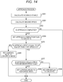
Fig. 14 is a flowchart for explaining an approach process executed by a printing device according to an embodiment of the present invention. -
Fig. 15 is a flowchart for explaining a normal process executed by a printing device according to an embodiment of the present invention. -
Fig. 16 is a flowchart for explaining a low-speed mode process executed by a printing device according to an embodiment of the present invention. -
Fig. 17 is a flowchart for explaining a high-speed mode process executed by a printing device according to an embodiment of the present invention. -
Fig. 18 is a flowchart for explaining an ejection process executed by a printing device according to an embodiment of the present invention. - Hereinafter, a printing device according to an embodiment of the present invention will be described with reference to the drawings. In the drawings, mutually same or equivalent configurations are denoted by mutually same reference numerals.
- A
printing device 1 shown inFig. 1 is a manual-scanning printing device that can be grasped by a user and moved on aprinting medium 2, and theprinting device 1 prints an image to be printed on theprinting medium 2 in accordance with the movement. A manual-scanning printing device is also called a handy printer, a handheld printer, or the like. It is to be noted that aprinting device 1 merely has to move relative to theprinting medium 2 during printing, and may be in a form such that, for example, theprinting device 1 is fixed while theprinting medium 2 is moved relative to theprinting device 1. - The image to be printed is an image that is to be printed on the
printing medium 2 by theprinting device 1. The image to be printed is also called a print image, a print pattern, or the like. Specific examples of images to be printed include letters, figures, symbols, patterns, pictures, combinations of these, and the like. - The
printing medium 2 is an object that is to be printed with an image to be printed during printing. Theprinting medium 2 is also called a printed medium, a recording medium, a print object, or the like. Specific examples of theprinting medium 2 include paper, cloth, a synthetic resin, a corrugated cardboard, a box, a bottle, and the like. Theprinting device 1, which is a manual-scanning printing device, can perform printing on a wider variety ofprinting medium 2 than a stationary printing device that performs printing while conveying theprinting medium 2. In other words, in addition to being able to perform printing on aprinting medium 2 such as paper that can be easily conveyed in a same manner as a stationary printing device, theprinting device 1 can also print on aprinting medium 2 such as cloth, a synthetic resin, a corrugated cardboard, a box, and a bottle that have a material and a shape difficult to convey, and are difficult to print with the stationary printing device. - A direction in which a user moves the
printing device 1 during printing is referred to as a moving direction. The moving direction is also referred to as a subscanning direction, a printing direction, or the like. To facilitate understanding, there are provided xyz coordinate axes shown inFig. 1 . Hereinafter, the x-axis positive direction is referred to as a right direction. Hereinafter, a case where a user moves theprinting device 1 in the right direction as the moving direction will be described as an example. - The
printing device 1 is provided with a low-speed mode and a high-speed mode as control modes. While details will be described later, theprinting device 1 sets the control mode of the own device to either the low-speed mode or the high-speed mode in accordance with a moving speed of the own device. Further, while details will be described later, theprinting device 1 performs printing with mutually different printing methods for cases where the control mode is set to the low-speed mode and where the control mode is set to the high-speed mode. - The
printing device 1 includes adevice body 100, astart button 101, adetector 102, and aprinting mechanism 103. Although thedetector 102 and theprinting mechanism 103 are incorporated in thedevice body 100 and actually not visually recognizable from outside, thedetector 102 and theprinting mechanism 103 are illustrated by broken lines to facilitate understanding inFig. 1 . - The
device body 100 is also called a housing or the like and is held by a user. Thedevice body 100 has anupper surface 100a and abottom surface 100b. Thebottom surface 100b is a surface facing theprinting medium 2 during printing. Theupper surface 100a is a surface opposite to thebottom surface 100b. - The
start button 101 accepts an instruction to start printing by the user. When thestart button 101 is pressed, a print start condition to be described later is satisfied. Thestart button 101 is disposed on theupper surface 100a of thedevice body 100, for example. - The
detector 102 detects a relative moving amount of theprinting device 1, with respect to theprinting medium 2. Thedetector 102 supplies the detected data representing the moving amount of theprinting device 1 to acontrol circuit 104 to be described later. Specifically, thedetector 102 includes an optical sensor (not shown), and outputs a detection signal to thecontrol circuit 104 for each preset sampling cycle. The detection signal includes a moving amount detection signal indicating a moving direction and a moving amount per sampling cycle of theprinting device 1 on theprinting medium 2. The sampling cycle is set in advance by any method such as experiment in accordance with a performance and the like of the optical sensor. The sampling cycle corresponds to Nts - (N - 1)ts (N is an integer of 1 or more) inFigs. 9A, 9B ,10A, and 10B , and is 500 µsec, for example. More specifically, thedetector 102 includes a laser optical sensor having an image sensor and a light source that irradiates a surface of theprinting medium 2 with a laser beam, and the image sensor captures the laser beam irradiated on the surface of theprinting medium 2 from the light source and reflected on the surface of theprinting medium 2. Thedetector 102 generates a detection signal including a moving amount detection signal by analyzing an interference fringe of the captured laser light, and outputs the generated detection signal to thecontrol circuit 104. - Based on the moving amount detection signal included in the detection signal output by the
detector 102, theprinting device 1 acquires a moving amount and a moving speed of theprinting device 1, which is the own device. Further, theprinting device 1 determines whether or not the own device has been lifted off, by determining whether or not the detection signal output by thedetector 102 satisfies a preset lift-off condition. Lift off means that theprinting device 1 is lifted up during printing and is separated from theprinting medium 2 by a preset lift-off distance or more. The lift-off condition and the lift-off distance are preset by any method such as experiment. Since it is not desirable that theprinting device 1 continues printing and continues to eject ink in the lift-off state, theprinting device 1 stops printing when lifted off as will be described later. - As shown in
Fig. 2 , thedetector 102 is provided to be exposed outside through an opening provided on thebottom surface 100b of thedevice body 100. - Returning to
Fig. 1 , theprinting mechanism 103 prints an image to be printed on theprinting medium 2 by an inkjet method of ejecting droplets of ink onto theprinting medium 2. - Specifically, as shown in
Fig. 2 , theprinting mechanism 103 includes anink jet head 103a. Theink jet head 103a is provided to be exposed outside through an opening provided on thebottom surface 100b of thedevice body 100. Theink jet head 103a is also called a printing head, a recording head, a print head, or the like. In accordance with control by an ink jethead control circuit 103b, which will be described later, theink jet head 103a performs printing by ejecting ink filled in an ink tank (not shown), onto theprinting medium 2. Theink jet head 103a and the above-described ink tank may be collectively referred to as an ink cartridge or the like. Theink jet head 103a functions as a printing head. Further, the above-describeddetector 102 detects a relative moving amount of theink jet head 103a with respect to theprinting medium 2 for each sampling cycle. - More specifically, the
ink jet head 103a has a nozzle row NL. The nozzle row NL is provided in parallel with the y-axis direction that is perpendicular to the x-axis and is parallel to a surface direction of theprinting medium 2. The nozzle row NL is arranged to be apart from a right end RE of thebottom surface 100b of thedevice body 100 by a distance DD to the left. As will be described later, when performing printing using theprinting device 1, the user moves theprinting device 1 while visually checking the right end RE of thebottom surface 100b, and sets a desired position as a printing start position. - The nozzle row NL each includes a plurality of ink nozzles (not shown). When ink inside the ink nozzle is heated by a heater, bubbles are generated, and a burst of this bubble causes the ink to be ejected from the ink nozzle to the
printing medium 2. - While details will be described later, when the control mode of the
printing device 1 is set to the low-speed mode, theprinting mechanism 103 prints an image to be printed by ejecting ink onto theprinting medium 2 each time thedetector 102 detects that theprinting device 1 has moved by a preset reference distance. The reference distance is set in advance by any method such as experiment in accordance with a printing resolution and the like of printing performed by theprinting device 1. Specifically, in the present embodiment, the reference distance is set to a dot pitch corresponding to a print resolution of printing performed by theink jet head 103a of theprinting device 1. For example, when the printing resolution is 600 dpi, the reference distance is set to 42.3 µm. While details will be described later, when the control mode of theprinting device 1 is set to the high-speed mode, theprinting mechanism 103 prints an image to be printed by ejecting ink onto theprinting medium 2 for each printing cycle corresponding to the moving speed of theprinting device 1. - The
printing mechanism 103 starts printing in response to the fact that theprinting device 1 has moved by a preset approach distance after a preset print start condition is satisfied. In the present embodiment, the print start condition is satisfied when thestart button 101 is pressed. Further, in the present embodiment, the distance DD between the right end RE of thebottom surface 100b of thedevice body 100 and the nozzle row NL is set as the approach distance. - The
printing mechanism 103 starts printing in response to the fact that theprinting device 1 has moved by the distance DD between the right end RE of thebottom surface 100b of thedevice body 100 and the nozzle row NL, which is the approach distance after thestart button 101 is pressed. Therefore when printing is performed using theprinting device 1, the user can move theprinting device 1 while visually checking the right end RE of thebottom surface 100b and set a desired position as a print start position. Hereinafter, a description is given to a function of the right end RE of thebottom surface 100b in setting a desired position as the printing start position in printing using theprinting device 1, with reference toFigs. 3 to 5 . Specifically, a case will be described where the user desires to set, as the printing start position, a position on theprinting medium 2 with the x coordinate of X1, as an example. - During printing, the user moves the
printing device 1 while visually checking the right end RE of thebottom surface 100b of thedevice body 100 in a state where theprinting device 1 is placed on theprinting medium 2, and places theprinting device 1 such that the x coordinate of the right end RE coincides with X1, as shown inFig. 3 . In this state, the nozzle row NL included in theink jet head 103a is disposed at a position with the x coordinate of X1-DD. In this state, printing is started when the user presses thestart button 101 to instruct a print start, and moves theprinting device 1 in the moving direction by the distance DD set as the approach distance between the right end RE and the nozzle row NL as shown inFig. 4 . At a time point when printing is started, the nozzle row NL to perform printing is disposed at a position with the x coordinate of X1. Thereafter, when the user continues to move theprinting device 1 in the moving direction, text "EFGHI" as an image to be printed is printed with the x coordinate of X1 as the printing start position, as shown inFig. 5 . - Hereinafter, an operation in which the
printing device 1 is moved by the approach distance after the print start condition is satisfied is referred to as approach. That is, theprinting device 1 starts printing in response to completion of approach. - In addition to each of the above-described configurations, the
printing device 1 includes, as shown inFig. 6 , thecontrol circuit 104, a read only memory (ROM) 105, a random access memory (RAM) 106, asensor control circuit 107, a powersupply control circuit 108, apower supply 109, the ink jethead control circuit 103b, awireless communication module 110, atimer circuit 111, an input/output control circuit 112, aninput unit 113, and anoutput unit 114. - The
control circuit 104 includes a central processing unit (CPU), and executes various processes including a print process to be described later, in accordance with a program and data stored in theROM 105. Thecontrol circuit 104 is connected to each part of theprinting device 1 via a system bus (not shown) that is a transmission path for command and data, and integrally controls theentire printing device 1. - The
ROM 105 stores a program and data to be used for executing various processes by thecontrol circuit 104. Specifically, theROM 105 stores acontrol program 105a to be executed by thecontrol circuit 104. Further, theROM 105 stores printdata 105b representing an image to be printed. Theprinting device 1 acquires theprint data 105b generated by an external device such as a personal computer (PC) or a smart phone, from the external device via thewireless communication module 110, and stores the data in theROM 105. - The
RAM 106 stores data generated or acquired by thecontrol circuit 104 executing various processes. Specifically, theRAM 106 stores movingamount data 106a representing a moving direction of theprinting device 1 and a moving amount per sampling cycle that are indicated by the moving amount detection signal output by thedetector 102. Further, theRAM 106 functions as a work area of thecontrol circuit 104. That is, thecontrol circuit 104 executes various processes by reading out the program and data stored in theROM 105 to theRAM 106, and appropriately referring to the read out program and data. - The
sensor control circuit 107 controls thedetector 102 in accordance with control by thecontrol circuit 104. The powersupply control circuit 108 controls thepower supply 109 in accordance with control by thecontrol circuit 104. Thepower supply 109 includes a battery and supplies power to each part of theprinting device 1 in accordance with control by the powersupply control circuit 108. - The ink jet
head control circuit 103b is provided in theprinting mechanism 103, and controls ejection of ink by theink jet head 103a in accordance with control by thecontrol circuit 104. Specifically, the ink jethead control circuit 103b sequentially transmits theprint data 105b to theink jet head 103a for each line in accordance with control by thecontrol circuit 104. Theprint data 105b for one line represents an image to be printed for one unit, which is an image of a portion that can be printed without movement of theprinting device 1, in the image to be printed. In accordance with control by thecontrol circuit 104, theprinting mechanism 103 sequentially prints the image to be printed for each unit. While details will be described later, when the control mode of theprinting device 1 is set to the low-speed mode, in accordance with control by thecontrol circuit 104, the ink jethead control circuit 103b sequentially transmits theprint data 105b for one line to theink jet head 103a each time thedetector 102 detects that theprinting device 1 has moved by the reference distance. Further, when the control mode of theprinting device 1 is set to the high-speed mode, in accordance with control by thecontrol circuit 104, the ink jethead control circuit 103b sequentially transmits theprint data 105b for one line to theink jet head 103a for each printing cycle corresponding to a moving speed of theprinting device 1. When the ink jethead control circuit 103b transmits theprint data 105b for one line to theink jet head 103a, the ink jethead control circuit 103b causes theink jet head 103a to eject ink from a specific ink nozzle specified by theprint data 105b among a plurality of ink nozzles included in the nozzle row NL, by transmitting an ejection command instructing ink ejection to theink jet head 103a, to perform printing. This causes printing of an image to be printed for one unit represented by theprint data 105b for one line. - The
wireless communication module 110 transmits and receives data with an external device such as a PC or a smart phone, by performing wireless communication via a communication network such as a wireless local area network (LAN). Specifically, theprinting device 1 acquires theprint data 105b generated by the external device, from the external device via thewireless communication module 110. Thetimer circuit 111 includes a real time clock (RTC) circuit that continues to generate a clock signal of a constant cycle even while power supply by thepower supply 109 is stopped, and always counts time based on the clock signal. Thetimer circuit 111 supplies data representing a time counting result to thecontrol circuit 104. The input/output control circuit 112 controls theinput unit 113 and theoutput unit 114 in accordance with control by thecontrol circuit 104. - The
input unit 113 includes an input device such as various operation buttons including thestart button 101, an input key, a switch, a touch pad, or a touch panel. Further, theinput unit 113 accepts various operation instructions input by the user, and supplies the accepted operation instruction to thecontrol circuit 104. Specifically, theinput unit 113 includes thestart button 101 and a sensor to detect depression of thestart button 101, and theinput unit 113 accepts an operation instruction to start printing in response to the depression of thestart button 101. Theoutput unit 114 includes an output device such as a speaker, a display, or a light emitting device, and outputs various information in a form recognizable by the user. - As a function of the
control circuit 104, theprinting device 1 having the above-described physical configuration includes a detectionsignal acquisition unit 10, a movingspeed calculation unit 11, a controlmode setting unit 12, and aprint control unit 13, as shown inFig. 7 . Thecontrol circuit 104 functions as each of these units by executing thecontrol program 105a to control theprinting device 1. The detectionsignal acquisition unit 10 acquires a detection signal including the above-described moving amount detection signal from thedetector 102 for each sampling cycle of the optical sensor provided to thedetector 102. The detectionsignal acquisition unit 10 supplies the acquired detection signal to the movingspeed calculation unit 11 and theprint control unit 13. - The moving
speed calculation unit 11 calculates a moving speed of theprinting device 1 in accordance with the moving amount detection signal included in the detection signal supplied from the detectionsignal acquisition unit 10. Specifically, the movingspeed calculation unit 11 calculates the moving speed of theprinting device 1 by dividing the moving amount, which is indicated by the moving amount detection signal, of theprinting device 1 per sampling cycle of the optical sensor provided to thedetector 102, by the sampling cycle. The movingspeed calculation unit 11 supplies data indicating the calculated moving speed, to the controlmode setting unit 12 and theprint control unit 13. - The control
mode setting unit 12 sets the control mode of theprinting device 1 to either the low-speed mode or the high-speed mode in accordance with the moving speed of theprinting device 1 calculated by the movingspeed calculation unit 11. The controlmode setting unit 12 supplies, to theprint control unit 13, data indicating whether the control mode of theprinting device 1 is set to the low-speed mode or to the high-speed mode. Specifically, while theprinting device 1 is performing printing, the controlmode setting unit 12 determines whether or not to switch the control mode of theprinting device 1 between the low-speed mode and the high-speed mode, in accordance with the moving speed of theprinting device 1 for each sampling cycle of the optical sensor provided to thedetector 102. - More specifically, as shown in
Fig. 8 , when it is determined that the moving speed of theprinting device 1 is lower than a first speed V1 set in advance in a state where the control mode of theprinting device 1 is set to the low-speed mode, the controlmode setting unit 12 maintains the control mode in the low-speed mode. Whereas, when it is determined that the moving speed of theprinting device 1 is lower than a maximum speed Vmax set in advance and is equal to or higher than the first speed V1 in a state where the control mode of theprinting device 1 is set to the low-speed mode, the controlmode setting unit 12 changes the control mode from the low-speed mode to the high-speed mode. - Further, when it is determined that the moving speed of the
printing device 1 is equal to or higher than the a second speed V2 set in advance and lower than the maximum speed Vmax in a state where the control mode of theprinting device 1 is set to the high-speed mode, the controlmode setting unit 12 maintains the control mode in the high-speed mode. Whereas, when it is determined that the moving speed of theprinting device 1 is lower than the second speed V2 in a state where the control mode of theprinting device 1 is set to the high-speed mode, the controlmode setting unit 12 changes the control mode from the high-speed mode to the low-speed mode. The second speed V2 is set to a speed lower than the first speed V1. That is, when the moving speed of theprinting device 1 is equal to or higher than the first speed V1 and is lower than the maximum speed Vmax, the controlmode setting unit 12 sets the control mode of theprinting device 1 to the high-speed mode, and when the moving speed of theprinting device 1 is lower than the second speed V2, the controlmode setting unit 12 sets the control mode of theprinting device 1 to the low-speed mode. - The maximum speed Vmax is set in advance by any method such as experiment, in accordance with a maximum value of a speed and the like at which the
printing mechanism 103 can perform printing without lowering print quality. In the present embodiment, the maximum speed Vmax is set to 200 mm/sec. If printing is performed when the moving speed of theprinting device 1 is equal to or higher than the maximum speed Vmax, an image to be printed may be stretched in the moving direction of theprinting device 1 to cause distorted print, lowering print quality. Therefore, as will be described later, in either case where the control mode of theprinting device 1 is set to the high-speed mode or the low-speed mode, when the moving speed of theprinting device 1 is equal to or higher than the maximum speed Vmax, theprint control unit 13 causes theprinting mechanism 103 to stop printing, thereby suppressing deterioration in print quality. - The first speed V1 and the second speed V2 are set in advance by any method such as experiment. In the present embodiment, the first speed V1 is set to 90 mm/sec and the second speed V2 is set to 45 mm/sec.
- In a case where the first speed V1, which is a threshold value at which the control mode of the
printing device 1 is switched from the low-speed mode to the high-speed mode, is an equal speed to the second speed V2, which is a threshold value at which the control mode of theprinting device 1 is switched from the high-speed mode to the low-speed mode, the control mode of theprinting device 1 is switched each time a magnitude relation between this same speed and the moving speed of theprinting device 1 changes. Whereas, in the present embodiment, the first speed V1 and the second speed V2 are mutually different. Therefore, in a state where the control mode of theprinting device 1 is set to the low-speed mode, even when the moving speed of theprinting device 1 falls below the first speed V1 after the control mode is changed from the low-speed mode to the high-speed mode based on the fact that the moving speed of theprinting device 1 is equal to or higher than the first speed V1, the control mode will not be changed from the high-speed mode to the low-speed mode unless the moving speed falls below the second speed V2. Further, in a state where the control mode of theprinting device 1 is set to the high-speed mode, even when the moving speed of theprinting device 1 becomes equal to or higher than the second speed V2 after the control mode is changed from the high-speed mode to the low-speed mode based on the fact that the moving speed of theprinting device 1 is lower than the second speed V2, the control mode will not be changed from the low-speed mode to the high-speed mode unless the moving speed becomes equal to or higher than the first speed V1. Therefore, in the present embodiment, a switching frequency of the control mode of theprinting device 1 is suppressed as compared with a case where the first speed V1 and the second speed V2 are the mutually same speed. - As the switching frequency of the control mode of the
printing device 1 increases, a processing load on theprinting device 1 increases. Further, since theprinting device 1 performs printing by a different printing method depending on the control mode, the printing method is switched very frequently when the switching frequency of the control mode becomes extremely large, which may cause deterioration in print quality. Therefore, by setting the first speed V1 and the second speed V2 to mutually different speeds, theprinting device 1 suppresses a switching frequency of the control mode, reduces a processing load, and reduces a possibility of deterioration in print quality. - As described above, while the
printing device 1 is performing printing, the controlmode setting unit 12 sets the control mode of theprinting device 1 in accordance with the moving speed of theprinting device 1. Further, the controlmode setting unit 12 sets the control mode of theprinting device 1 at a start of printing in accordance with the moving speed of theprinting device 1 during a period from after the above-described printing condition is satisfied until theprinting device 1 moves by the approach distance, that is, in accordance with the moving speed of theprinting device 1 during approach. In other words, the controlmode setting unit 12 sets the control mode of theprinting device 1 at a start of printing in accordance with the moving speed of theprinting device 1 in a state where the print start condition is satisfied but the printing is not yet started. - Specifically, when the moving speed of the
printing device 1 during the approach satisfies a first condition set in advance, the controlmode setting unit 12 sets the control mode of theprinting device 1 at a start of printing to the low-speed mode. In the present embodiment, the first condition is satisfied when an approach speed, which is an average value of the moving speed of theprinting device 1 during approach, is lower than the first speed V1. When the moving speed of theprinting device 1 during approach satisfies a second condition set in advance, the controlmode setting unit 12 sets the control mode of theprinting device 1 at a start of printing to the high-speed mode. In the present embodiment, the second condition is satisfied when the approach speed is equal to or higher than the first speed V1 and is lower than the maximum speed Vmax. - The
print control unit 13 controls theprinting mechanism 103 to print the image to be printed. Specifically, in response to the fact that theprinting device 1 has moved by the approach distance after the above-described print start condition is satisfied, that is, in response to completion of the approach, theprint control unit 13 causes theprinting mechanism 103 to start printing. In other words, in accordance with control by theprint control unit 13, theprinting mechanism 103 starts printing in response to completion of approach. - The
print control unit 13 causes theprinting mechanism 103 to perform printing using mutually different printing methods for cases where the control mode of theprinting device 1 is set to the low-speed mode and where the control mode of theprinting device 1 is set to the high-speed mode. Specifically, when the control mode of theprinting device 1 is set to the low-speed mode, theprint control unit 13 causes theprinting mechanism 103 to print an image to be printed by ejecting ink onto theprinting medium 2 each time thedetector 102 detects that theprinting device 1 has moved by the reference distance described above. Hereinafter, a description is given to printing by theprinting device 1 when the control mode of theprinting device 1 is set to the low-speed mode, with reference toFigs. 9A and 9B . - The
detector 102 outputs a moving amount detection signal indicating the moving amount of theprinting device 1 for each sampling cycle of the optical sensor provided to thedetector 102. Hereinafter, a description is given to a case where thedetector 102 outputs a moving amount detection signal at each timing of times ts to 9ts as an example, as shown inFig. 9A . Each time thedetector 102 outputs the moving amount detection signal, theprint control unit 13 acquires the output moving amount detection signal via the detectionsignal acquisition unit 10, and by successively adding the moving amount per sampling cycle of theprinting device 1 indicated by the acquired moving amount detection signal, theprint control unit 13 updates an accumulated value of the moving amount of theprinting device 1. Specifically, as shown inFig. 9B , theprint control unit 13 updates the accumulated value of the moving amount of theprinting device 1 at each timing of the times ts to 9ts, which is a timing at which the moving amount detection signal is output by thedetector 102. When the updated accumulated value of the moving amount of theprinting device 1 becomes equal to or larger than a reference distance L, theprint control unit 13 causes theprinting mechanism 103 to eject ink to perform printing. Specifically, as shown inFig. 9B , theprint control unit 13 calculates times T1 and T2 when the accumulated value of the moving amount of theprinting device 1 becomes the reference distance L, and causes theprinting mechanism 103 to eject ink at each timing of the times T1 and T2 to perform printing. When theprinting mechanism 103 ejects ink to perform printing, theprint control unit 13 subtracts the reference distance L from the accumulated value of the moving amount of theprinting device 1 as shown inFig. 9B . By repeatedly performing the above-described operation, theprinting device 1 causes theprinting mechanism 103 to eject ink to perform printing each time thedetector 102 detects that theprinting device 1 has moved by the reference distance L. - When the control mode of the
printing device 1 is set to the high-speed mode, theprint control unit 13 causes theprinting mechanism 103 to print an image to be printed by ejecting ink onto theprinting medium 2 for each printing cycle corresponding to the moving speed of theprinting device 1 calculated by the movingspeed calculation unit 11. Hereinafter, a description is given to printing by theprinting device 1 when the control mode of theprinting device 1 is set to the high-speed mode, with reference toFig. 10 . - The
detector 102 outputs a moving amount detection signal indicating the moving amount of theprinting device 1 for each sampling cycle of the optical sensor provided to thedetector 102. Hereinafter, a description is given to a case where thedetector 102 outputs a moving amount detection signal at each timing of the times ts to 9ts, as an example as shown inFig. 10A . Each time thedetector 102 outputs the moving amount detection signal, the movingspeed calculation unit 11 acquires the output moving amount detection signal via the detectionsignal acquisition unit 10, and calculates the moving speed of theprinting device 1 in accordance with the moving amount of theprinting device 1 indicated by the acquired moving amount detection signal. Here, as shown inFig. 10A , the moving distance at each timing is larger than the reference distance L. As shown inFig. 10B , at each timing of the times ts to 9ts, which is a timing at which the moving amount detection signal is output by thedetector 102, theprint control unit 13 sets the printing cycle corresponding to the moving speed of theprinting device 1 calculated by the movingspeed calculation unit 11. More specifically, theprint control unit 13 calculates the printing cycle corresponding to the moving speed by dividing the reference distance L by the moving speed of theprinting device 1. That is, the printing cycle corresponds to a time that theprinting device 1 moves by the reference distance L. At each time of detecting an elapse of the set printing cycle based on time counting by thetimer circuit 111, theprint control unit 13 causes theprinting mechanism 103 to eject ink to perform printing. Specifically, as shown inFig. 10B , theprint control unit 13 calculates times Ta to Tu at which the printing cycle has elapsed based on time counting by thetimer circuit 111, and causes theprinting mechanism 103 to eject ink at each timing of the times Ta to Tu to perform printing. For example, at each timing of the times Ta to Tc calculated that the printing cycle that is set at the timing of the time ts has elapsed based on time counting by thetimer circuit 111, theprint control unit 13 causes theprinting mechanism 103 to eject ink to perform printing. Further, at each timing of the times Td and Te calculated that the printing cycle that is set at the timing of time 2ts has elapsed based on time counting by thetimer circuit 111, theprint control unit 13 causes theprinting mechanism 103 to eject ink to perform printing. - As described above, when the moving speed of the
printing device 1 is lower than the second speed V2, the controlmode setting unit 12 sets the control mode of theprinting device 1 to the low-speed mode, and when the moving speed of theprinting device 1 is equal to or higher than the first speed V1 and is lower than the maximum speed Vmax, the controlmode setting unit 12 sets the control mode of theprinting device 1 to the high-speed mode. Therefore, in accordance with control by theprint control unit 13, when the moving speed of theprinting device 1 is lower than the second speed V2, theprinting mechanism 103 prints an image to be printed by ejecting ink onto theprinting medium 2 each time thedetector 102 detects that theprinting device 1 has moved by the reference distance L, and when the moving speed of theprinting device 1 is equal to or higher than the first speed V1 and is lower than the maximum speed Vmax, theprinting mechanism 103 prints an image to be printed by ejecting ink onto theprinting medium 2 for each printing cycle corresponding to the moving speed of theprinting device 1. Note that the speed lower than the second speed V2 is an example of a first moving speed according to the present invention, and the speed that is equal to or higher than the first speed V1 and is lower than the maximum speed Vmax is an example of a second moving speed according to the present invention. - Further, as described above, in a state where the control mode of the
printing device 1 is set to the low-speed mode, when the moving speed of theprinting device 1 is equal to or higher than the first speed V1 and is lower than the maximum speed Vmax, the controlmode setting unit 12 changes the control mode of theprinting device 1 from the low-speed mode to the high-speed mode. Therefore, in accordance with control by theprint control unit 13, in a state of printing an image to be printed by ejecting ink onto theprinting medium 2 each time thedetector 102 detects that theprinting device 1 has moved by the reference distance L, when the moving speed of theprinting device 1 is equal to or higher than the first speed V1 and is lower than the maximum speed Vmax, theprinting mechanism 103 stops operation of printing of an image to be printed by ejecting ink onto theprinting medium 2 each time thedetector 102 detects that theprinting device 1 has moved by the reference distance L, and theprinting mechanism 103 starts operation of printing of an image to be printed by ejecting ink onto theprinting medium 2 for each printing cycle corresponding to the moving speed of theprinting device 1. - Further, as described above, in a state where the control mode of the
printing device 1 is set to the high-speed mode, when the moving speed of theprinting device 1 is lower than the second speed V2, the controlmode setting unit 12 changes the control mode of theprinting device 1 from the high-speed mode to the low-speed mode. Therefore, in accordance with control by theprint control unit 13, in a state of printing an image to be printed by ejecting ink onto theprinting medium 2 for each printing cycle corresponding to the moving speed of theprinting device 1, when the moving speed of theprinting device 1 is lower than the second speed V2, theprinting mechanism 103 stops operation of printing of an image to be printed by ejecting ink onto theprinting medium 2 for each printing cycle corresponding to the moving speed of theprinting device 1, and theprinting mechanism 103 starts operation of printing of an image to be printed by ejecting ink onto theprinting medium 2 each time thedetector 102 detects that theprinting device 1 has moved by the reference distance L. - In a conventional printing device, in a state of printing an image to be printed by ejecting ink each time the detector detects that the own device has moved by the reference distance L, when the moving amount of the printing device per sampling cycle of the optical sensor provided to the detector exceeds a distance twice the reference distance L, it is not possible to eject twice or more of ink at each reference distance L although it is necessary to eject twice or more of ink at each reference distance L, which may deteriorate print quality. However, in a state where the control mode is set to the high-speed mode, the
printing device 1 according to the present embodiment prints an image to be printed by ejecting ink for each printing cycle shorter than the sampling cycle in accordance with the moving speed of theprinting device 1, thereby suppressing deterioration in print quality when the moving amount of theprinting device 1 per sampling cycle is larger than the reference distance L. - Further, in a conventional printing device, in a state of printing an image to be printed by ejecting ink for each printing cycle corresponding to the moving speed of the printing device, when the printing device stops moving or the moving amount of the printing device per sampling cycle falls below the reference distance L, ejection of ink for each reference distance may fail and print quality may be deteriorated. In the
printing device 1 of the present embodiment, in a state where the control mode is set to the low-speed mode, printing of an image to be printed is performed by ejecting ink each time thedetector 102 detects that theprinting device 1 has moved by the reference distance L, thereby suppressing deterioration in print quality when theprinting device 1 stops moving during printing or when a moving amount of theprinting device 1 per sampling cycle falls below the reference distance L. - Hereinafter, a description is given to printing by the
printing device 1 in cases where the control mode of theprinting device 1 is set to the low-speed mode and where the control mode is set to the high-speed mode, with reference toFigs. 11A and 11B . Specifically, hereinafter, as shown inFig. 11A , a case will be described, as an example, where theprinting device 1 moves at a speed lower than the second speed V2 from atime 0 to a time Tx, and moves at a speed that is higher than the first speed V1 and is lower than the maximum speed Vmax after the time Tx. As shown inFig. 11A , the control mode of theprinting device 1 is set to the low-speed mode from thetime 0 to the time Tx, and to the high-speed mode after the time Tx. - As shown in
Fig. 11B , in a time section from thetime 0 to the time Tx where the control mode is set to the low-speed mode, theprinting device 1 ejects ink at timings of times ta and tb, which are timings when thedetector 102 detects that theprinting device 1 has moved by the reference distance L, to perform printing. As shown inFig. 11B , the timing of the time ta is a timing at which the moving distance of theprinting device 1 reaches the reference distance L, and the timing of the time tb is a timing at which the moving distance of theprinting device 1 reaches 2L, which is a distance twice the reference distance L. - As shown in
Fig. 11B , in a time section after the time Tx where the control mode is set to the high-speed mode, theprinting device 1 ejects ink at timings of times tc to tg, which are timings of detecting an elapse of the printing cycle corresponding to the moving speed of theprinting device 1 based on time counting by thetimer circuit 111, to perform printing. As shown inFig. 11B , the times tc to tg are timings at which the moving distance of theprinting device 1 reaches 3L to 7L, which are distances 3 to 7 times the reference distance L, respectively. - As shown in
Fig. 11B , a time interval between the time ta and the time tb is different from each time interval between the times tc and tg. That is, a time interval of ink ejection in a case where the control mode of theprinting device 1 is set to the low-speed mode is set longer than a time interval of ink ejection in a case where the control mode of theprinting device 1 is set to the high-speed mode. Whereas, as shown inFig. 11B , through the cases where the control mode is set to the low-speed mode and where the control mode is set to the high-speed mode, theprinting device 1 ejects ink each time the moving distance of the own device increases by the reference distance L, to perform printing. That is, a distance interval of ink ejection in a case where the control mode of theprinting device 1 is set to the low-speed mode is equal to a distance interval of ink ejection in a case where the control mode of theprinting device 1 is set to the high-speed mode. - As described above, the
printing device 1 performs printing by mutually different printing methods for the cases where the control mode is set to the low-speed mode and where the control mode is set to the high-speed mode, and ejects ink at the same distance interval between the cases where the control mode is set to the low-speed mode and where the control mode is set to the high-speed mode, by ejecting ink at mutually different time intervals between the cases where the control mode is set to the low-speed mode and where the control mode is set to the high-speed mode. That is, theprinting device 1 performs printing with mutually different printing methods for cases where the control mode is set to the low-speed mode and where the control mode is set to the high-speed mode, thereby suppressing deterioration in print quality. - As described above, when the moving speed of the
printing device 1 during approach satisfies the first condition set in advance, the controlmode setting unit 12 sets the control mode of theprinting device 1 at a start of printing to the low-speed mode. Further, when the moving speed of theprinting device 1 during the approach satisfies the second condition set in advance, the controlmode setting unit 12 sets the control mode of theprinting device 1 at a start of printing to the high-speed mode. Therefore, in accordance with control by theprint control unit 13, in a case where the moving speed of theprinting device 1 during approach satisfies the first condition, theprinting mechanism 103 prints an image to be printed by ejecting ink onto theprinting medium 2 each time thedetector 102 detects that theprinting device 1 has moved by the reference distance L, when the printing is started. Further, in accordance with control by theprint control unit 13, in a case where the moving speed of theprinting device 1 during approach satisfies the second condition, theprinting mechanism 103 prints an image to be printed by ejecting ink onto theprinting medium 2 for each printing cycle that is set in accordance with the moving speed of theprinting device 1, when the printing is started. - As described above, the
printing device 1 sets the control mode of theprinting device 1 at a start of printing in accordance with the moving speed of theprinting device 1 during approach. Further, as described above, theprinting device 1 suppresses deterioration in print quality by performing printing by a printing method corresponding to the control mode. That is, theprinting device 1 suppresses the deterioration in print quality by setting the control mode of theprinting device 1 at a start of printing in accordance with the moving speed of theprinting device 1 during approach. - The
print control unit 13 determines whether or not theprinting device 1 has been lifted off, by determining whether or not a detection signal supplied from the detectionsignal acquisition unit 10 satisfies the lift-off condition described above. When determining that theprinting device 1 has been lifted off, theprint control unit 13 causes theprinting mechanism 103 to stop printing. That is, in accordance with control by theprint control unit 13, theprinting mechanism 103 stops printing in response to the lift off of theprinting device 1. - When the moving speed of the
printing device 1 calculated by the movingspeed calculation unit 11 is equal to or higher than the maximum speed Vmax, theprint control unit 13 causes theprinting mechanism 103 to stop printing. Further, when the above-described approach speed is equal to or higher than the maximum speed Vmax, theprint control unit 13 causes theprinting mechanism 103 to stop printing. That is, in accordance with control by theprint control unit 13, theprinting mechanism 103 stops printing when the moving speed of theprinting device 1 is equal to or higher than the maximum speed Vmax. Therefore, theprinting device 1 can suppress deterioration in print quality. - Hereinafter, a description is given to a print process executed by the
printing device 1 having the above-described physical/functional configuration, with reference to the flowcharts ofFigs. 12 to 18 . - The
printing device 1 acquires theprint data 105b generated by an external device such as a PC or a smart phone from the external device via thewireless communication module 110, and stores the data in theROM 105 in advance. When a user selects theprint data 105b by operating theinput unit 113, thecontrol circuit 104 reads out theprint data 105b to theRAM 106. In this state, when the user instructs a start of printing by pressing thestart button 101, thecontrol circuit 104 starts the print process shown in the flowchart ofFig. 12 . - When the print process is started, the
control circuit 104 firstly sets interruption of the control process to be described later and starts the control process (step S101). Thereafter, until the interruption of the control process is stopped in processing of step S105 to be described later, thecontrol circuit 104 causes a control process to interrupt at each time of detecting an elapse of the sampling cycle of the optical sensor provided to thedetector 102 based on time counting by thetimer circuit 111, and repeatedly executes the control process. Details of the control process will be described later with reference to the flowcharts ofFigs. 13 to 18 . - Next, the
print control unit 13 determines whether or not an error flag is set to an ON state (step S102). As will be described later, the error flag is set to the ON state (step S206, step S309, step S510, step S705) when it is determined that theprinting device 1 has been lifted off (step S202; Yes); when it is determined that an approach speed, which is an average value of the moving speed of theprinting device 1 during approach, is equal to or higher than the maximum speed Vmax (step S307; No); and when it is determined that the moving speed of theprinting device 1 is equal to or higher than the maximum speed Vmax (step S509; No, step S704; No). - When it is determined that the error flag is set to the ON state (step S102; Yes), the
print control unit 13 clears the error flag and an approach completion flag to be described later (step S104), stops the interruption of the control process (step S105), and ends the print process. Clearing the error flag and the approach completion flag indicates setting these flags to an OFF state, which is an initial state. Clearing these flags at the end of the print process allows execution of the next print process. - Whereas, when it is determined that the error flag is not set to the ON state (step S102; No), the
print control unit 13 determines whether or not printing has been completed, by determining whether or not theprint data 105b is stored in the RAM 106 (step S103). As will be described later, theprint control unit 13 transmits theprint data 105b to theink jet head 103a for each line to print an image to be printed for each unit (steps S503 and S504, steps S601 and S602), and deletes the transmittedprint data 105b from theRAM 106 for each line (step S505, step S603). Therefore, by determining whether or not theprint data 105b is stored in theRAM 106, theprint control unit 13 can determine whether or not the printing of the image to be printed represented by theprint data 105b has been completed. - When the
print control unit 13 determines that printing has not been completed (step S103; No), the process returns to step S102. Whereas, when it is determined that the printing is completed (step S103; Yes), theprint control unit 13 clears the error flag and the approach completion flag to be described later (step S104), stops the interruption of the control process (step S105), and ends the print process. - Next, details of the control process will be described with reference to the flowcharts of
Figs. 13 to 18 . - When the control process shown in the flowchart of
Fig. 13 is started, first, the detectionsignal acquisition unit 10 acquires a detection signal from the detector 102 (step S201). - The
print control unit 13 determines whether or not theprinting device 1 has been lifted off, by determining whether or not the detection signal acquired in step S201 satisfies the lift-off condition (step S202). When it is determined that theprinting device 1 has been lifted off (step S202; Yes), theprint control unit 13 sets the error flag to the ON state (step S206), and ends the control process. - Whereas, when the
print control unit 13 determines that theprinting device 1 has not been lifted off (step S202; No), thecontrol circuit 104 determines whether or not the approach completion flag is set to ON (step S203). As will be described later, the approach completion flag is set to the ON state (step S304) in response to the determination that the approach has been completed (step S303: Yes). - When it is determined that the approach completion flag is set to the ON state (step S203; Yes), the
control circuit 104 executes a normal process to be described later (step S204) and ends the control process. Whereas, when it is determined that the approach completion flag is not set to the ON state (step S203; No), thecontrol circuit 104 executes an approach process to be described later (step S205) and ends the control process. - Hereinafter, details of the approach process will be described with reference to the flowchart of
Fig. 14 . - When the approach process shown in the flowchart of
Fig. 14 is started, first, in accordance with the moving amount of theprinting device 1 indicated by the moving amount detection signal included in the detection signal acquired in step S201 of the flowchart ofFig. 13 , thecontrol circuit 104 calculates the moving distance of theprinting device 1 from a time point when thestart button 101 is pressed (step S301). - Next, the moving
speed calculation unit 11 calculates the moving speed of theprinting device 1 in accordance with the moving amount of theprinting device 1 indicated by the moving amount detection signal included in the detection signal acquired in step S201 (step S302). - The
control circuit 104 determines whether or not the approach has been completed, by determining whether or not the moving distance calculated in step S301 is equal to or larger than the approach distance (step S303). When it is determined that the approach has not been completed (step S303; No), thecontrol circuit 104 ends the approach process. Whereas, when it is determined that the approach has been completed (step S303; Yes), thecontrol circuit 104 sets the approach completion flag to the ON state (step S304). - During a period from after the
start button 101 is pressed before it is determined that the approach has been completed in step S303 (step S303: Yes), the controlmode setting unit 12 determines whether or not the approach speed, which is an average value of the moving speed of theprinting device 1 calculated in step S302, is equal to or higher than the first speed V1 (step S305). When it is determined that the approach speed is lower than the first speed V1 (step S305; No), the controlmode setting unit 12 sets the control mode of theprinting device 1 at a start of printing to the low-speed mode (step S306), and ends the approach process. - Whereas, when it is determined that the approach speed is equal to or higher than the first speed V1 (step S305; Yes), the control
mode setting unit 12 determines whether or not the approach speed is lower than the maximum speed Vmax (step S307). When it is determined that the approach speed is lower than the maximum speed Vmax (step S307; Yes), the controlmode setting unit 12 sets the control mode of theprinting device 1 at a start of printing to the high-speed mode (step S308), and ends the approach process. Whereas, when it is determined that the approach speed is equal to or higher than the maximum speed Vmax (step S307; No), the controlmode setting unit 12 sets the error flag to the ON state (step S309), and ends the approach process. - Next, details of the normal process will be described with reference to the flowcharts of
Figs. 15 to 18 . - When the normal process shown in the flowchart of
Fig. 15 is started, first, in accordance with the moving amount of theprinting device 1 indicated by the moving amount detection signal included in the detection signal acquired in step S201 of the flowchart ofFig. 13 , the movingspeed calculation unit 11 calculates the moving speed of the printing device 1 (step S401). - Next, the
control circuit 104 determines whether or not the control mode of theprinting device 1 is set to the low-speed mode (step S402). When it is determined that the control mode is set to the low-speed mode (step S402; Yes), thecontrol circuit 104 executes a low-speed mode process to be described later (step S403) and ends the normal process. Whereas, when it is determined that the control mode is not set to the low-speed mode (step S402; No), thecontrol circuit 104 executes a high-speed mode process to be described later (step S404) and ends the normal process. - Hereinafter, details of the low-speed mode process will be described with reference to the flowchart of
Fig. 16 . - When the low-speed mode process shown in the flowchart of
Fig. 16 is started, first, theprint control unit 13 updates an accumulated value of the moving amount of the printing device 1 (step S501) by adding the moving amount per sampling cycle of theprinting device 1 indicated by the moving amount detection signal included in the detection signal acquired in step S201 of the flowchart ofFig. 13 . - The
print control unit 13 determines whether or not the accumulated value of the moving amount of theprinting device 1 updated in step S501 is equal to or larger than the reference distance L (step S502). When theprint control unit 13 determines that the accumulated value is smaller than the reference distance L (step S502; No), the process proceeds to step S508. - Whereas, when it is determined that the accumulated value of the moving amount of the
printing device 1 is equal to or larger than the reference distance L (step S502; Yes), theprint control unit 13 causes the ink jethead control circuit 103b to transmit, to theink jet head 103a, theprint data 105b for one line in theprint data 105b read out to the RAM 106 (step S503). By causing the ink jethead control circuit 103b to transmit an ejection command to theink jet head 103a (step S504), theprint control unit 13 causes theink jet head 103a to eject ink to perform printing. Theprint control unit 13 deletes theprint data 105b for one line (step S505) that has been transmitted in step S503, in theprint data 105b read out to theRAM 106. Next, when it is determined thatunprinted data 105b to be printed remains in theRAM 106 after deletion (step S506; Yes), theprint control unit 13 subtracts the reference distance L from the accumulated value of the moving amount of the printing device 1 (step S507), and the process proceeds to step S508. When it is determined thatunprinted data 105b to be printed does not remain in the RAM 106 (step S506; No), the low-speed processing mode is ended. - Next, the control
mode setting unit 12 determines whether or not the moving speed of theprinting device 1 calculated in step S401 of the flowchart ofFig. 15 is equal to or higher than the first speed V1 (step S508). When it is determined that the moving speed of theprinting device 1 is lower than the first speed V1 (step S508; No), the controlmode setting unit 12 continues to consider that it is the low-speed mode, and the process returns to step 501. - Whereas, when it is determined that the moving speed of the
printing device 1 is equal to or higher than the first speed V1 (step S508; Yes), the controlmode setting unit 12 determines whether or not the moving speed of theprinting device 1 calculated in step S401 is lower than the maximum speed Vmax (step S509). When it is determined that the moving speed of theprinting device 1 is equal to or higher than the maximum speed Vmax (step S509; No), the controlmode setting unit 12 sets the error flag to the ON state (step S510), and ends the low-speed mode process. - Whereas, when it is determined that the moving speed of the
printing device 1 is lower than the maximum speed Vmax (step S509; Yes), the controlmode setting unit 12 changes the control mode of theprinting device 1 from the low-speed mode to the high-speed mode (step S511). - The
print control unit 13 sets the printing cycle in accordance with the moving speed of theprinting device 1 calculated in step S401 (step S512). Theprint control unit 13 sets interruption of the ejection process to be described later and starts the ejection process (step S513), and the process proceeds to step S601. Thereafter, until the interruption of the control process is stopped in processing of step S105 of the flowchart ofFig. 12 , or the interruption of the ejection process is stopped in processing of step S703 to be described later, theprint control unit 13 causes the ejection process to interrupt at each time of detecting an elapse of the printing cycle set in step S512 based on time counting by thetimer circuit 111, and repeatedly executes the ejection process. - Next, details of the high-speed mode process will be described with reference to the flowchart of
Fig. 17 . - When the high-speed mode process shown in the flowchart of
Fig. 17 is started, the controlmode setting unit 12 determines whether or not the moving speed of theprinting device 1 calculated in step S401 of the flowchart ofFig. 15 is lower than the second speed V2 (step S701). When it is determined that the moving speed of theprinting device 1 is lower than the second speed V2 (step S701: Yes), the controlmode setting unit 12 changes the control mode of theprinting device 1 from the high-speed mode to the low-speed mode (step S702). Theprint control unit 13 stops interruption of the ejection process (step S703) and ends the high-speed mode process, and the process proceeds to a process step S501 of the low-speed mode. - Whereas, when it is determined that the moving speed of the
printing device 1 is equal to or higher than the second speed V2 (step S701; No), the controlmode setting unit 12 determines whether or not the moving speed of theprinting device 1 calculated in step S401 is lower than the maximum speed Vmax (step S704). When it is determined that the moving speed of theprinting device 1 is equal to or higher than the maximum speed Vmax (step S704; No), the controlmode setting unit 12 sets the error flag to the ON state (step S705) and ends the high-speed mode process. - Whereas, when the control
mode setting unit 12 determines that the moving speed of theprinting device 1 is lower than the maximum speed Vmax (step S704; Yes), theprint control unit 13 calculates the printing cycle corresponding to the moving speed of theprinting device 1 calculated in step S401 (step S706). Theprint control unit 13 updates the printing cycle for executing the interruption of the ejection process to the printing cycle calculated in step S706 (step S707), and the process proceeds to step S601 of the ejection process to be described later. That is, in a state where the control mode is set to the high-speed mode, theprinting device 1 updates the printing cycle for executing the interruption of the ejection process in accordance with the moving speed of the own device for each sampling cycle of the optical sensor provided to thedetector 102 by executing processing of step S707, and the process proceeds to step S601 of the ejection process to be described later. - When the ejection process shown in the flowchart of
Fig. 18 is started, theprint control unit 13 causes the ink jethead control circuit 103b to transmit, to theink jet head 103a, theprint data 105b for one line in theprint data 105b read out to the RAM 106 (step S601). By causing the ink jethead control circuit 103b to transmit an ejection command to theink jet head 103a (step S602), theprint control unit 13 causes theink jet head 103a to eject ink to perform printing. Theprint control unit 13 deletes theprint data 105b for one line (step S603) that has been transmitted in step S601, in theprint data 105b read out to theRAM 106. When it is determined thatunprinted data 105b to be printed remains in theRAM 106 after the deletion (step S604; Yes), the process proceeds to step S701 of the high-speed mode process, and when it is determined thatunprinted data 105b to be printed does not remain in the RAM 106 (step S604; No), the ejection process is ended. - As described above, the
printing device 1 sets the control mode to the low-speed mode when the moving speed of theprinting device 1 is lower than the second speed V2, and theprinting device 1 sets the control mode to the high-speed mode when the moving speed of theprinting device 1 is equal to or higher than the first speed V1 and is lower than the maximum speed Vmax. When the control mode is set to the low-speed mode, theprinting device 1 prints an image to be printed by ejecting ink each time thedetector 102 detects that theprinting device 1 has moved by the reference distance L. Therefore, theprinting device 1 can suppress deterioration in print quality when theprinting device 1 stops moving during printing, or when a moving amount of theprinting device 1 per sampling cycle of the optical sensor provided to thedetector 102 is smaller than the reference distance L. Further, when the control mode is set to the high-speed mode, theprinting device 1 prints an image to be printed by ejecting ink for each printing cycle corresponding to the moving speed of theprinting device 1. Therefore, theprinting device 1 can suppress the deterioration in print quality when the moving amount of theprinting device 1 per sampling cycle is larger than the reference distance L. That is, theprinting device 1 sets the control mode in accordance with the moving speed of theprinting device 1, and performs printing by the printing method according to the control mode, thereby enabling suppression of deterioration in print quality. - Further, the
printing device 1 sets the control mode of theprinting device 1 at a start of printing in accordance with the moving speed of theprinting device 1 during approach. Therefore, theprinting device 1 can suppress deterioration in print quality at the start of printing. - Further, when the control mode is set to the high-speed mode, the
printing device 1 determines whether or not to switch the control mode in accordance with the relationship between the second speed V2 and the moving speed of theprinting device 1. Whereas, when the control mode is set to the low-speed mode, theprinting device 1 determines whether or not to switch the control mode in accordance with the relationship between the first speed V1 higher than the second speed V2 and the moving speed of theprinting device 1. Therefore, theprinting device 1 can suppress a switching frequency of the control mode, reduce a processing load, and reduce a possibility of deterioration in print quality. - Although the embodiment of the present invention has been described above, the above-described embodiment is merely an example, and the application range of the present invention is not limited to this. That is, the embodiment of the present invention can be applied in various ways, and all embodiments fall within the scope of the present invention.
- For example, in the above-described embodiment, it is described that the first speed V1 is a speed higher than the second speed V2. However, this is merely an example, and the first speed V1 and the second speed V2 may be the same speed as each other.
- Further, in the above-described embodiment, it is described that the print start condition is satisfied when the
start button 101 is pressed. However, this is merely an example, and any conditions can be set as the print start condition. For example, the print start condition may be satisfied when theprinting device 1 starts moving. - In the above-described embodiment, it is described that the control mode of the
printing device 1 at a start of printing is set in accordance with the moving speed of theprinting device 1 during approach. However, this is merely an example, and the control mode of theprinting device 1 at a start of printing may be set in advance. For example, the low-speed mode may be set in advance as the control mode of theprinting device 1 at the start of printing. Alternatively, the high-speed mode may be set in advance as the control mode of theprinting device 1 at the start of printing. - In the above-described embodiment, it is described that the first condition is satisfied when the approach speed, which is an average value of the moving speed of the
printing device 1 during approach, is lower than the first speed V1, and the second condition is satisfied when the approach speed is equal to or higher than the first speed V1 and is lower than the maximum speed Vmax. However, this is merely an example, and any conditions can be set as the first condition and the second condition. For example, the first condition may be satisfied when the approach speed is lower than the second speed V2, and the second condition may be satisfied when the approach speed is equal to or higher than the second speed V2 and is lower than the maximum speed Vmax. Alternatively, the first condition may be satisfied when a terminal speed, which is a moving speed having the latest time calculated by the movingspeed calculation unit 11 among moving speeds of theprinting device 1 during approach, is lower than the first speed V1, and the second condition may be satisfied when the terminal speed is equal to or higher than the first speed V1 and is lower than the maximum speed Vmax. Alternatively, the first condition may be satisfied when the terminal speed is lower than the second speed V2, and the second condition may be satisfied when the terminal speed is equal to or higher than the second speed V2 and is lower than the maximum speed Vmax. - Further, in the above-described embodiment, it is described that the distance DD between the right end RE of the
bottom surface 100b of thedevice body 100 and the nozzle row NL is set as the approach distance. However, this is merely an example, and any distance can be set as the approach distance. For example, it is possible to guide a position of theink jet head 103a to a user, provide an auxiliary member to assist setting of the print start position by the user at the right end RE of thebottom surface 100b, and set the distance between the auxiliary member and the nozzle row NL as the approach distance. Further, in the above-described embodiment, it is described that theprinting mechanism 103 performs printing by the inkjet method. However, this is merely an example, and theprinting mechanism 103 may perform printing by any method. For example, theprinting mechanism 103 may perform printing by a thermal method or a thermal transfer method. - In the above-described embodiment, it is described that the
printing device 1 acquires theprint data 105b generated by an external device, from the external device via thewireless communication module 110. However, this is merely an example, and theprinting device 1 can acquire theprint data 105b by any method. For example, theprinting device 1 may include a wired communication interface such as a universal serial bus (USB) port, and may transmit and receive data with an external storage medium using the wired communication interface thereby to acquire theprint data 105b stored in the storage medium. Alternatively, theprinting device 1 may accept an input of print contents using theinput unit 113 by the user without externally receiving the print data, and may generate theprint data 105b in accordance with the input print contents. - Further, in the above-described embodiment, it is described that the
printing device 1 is a manual-scanning printing device. However, this is merely an example, and theprinting device 1 may be a self-propelled printing device having a moving unit configured to move the own device on theprinting medium 2 to perform printing in accordance with the movement. - Further, in the above-described embodiment, it is described that the
detector 102 includes the optical sensor, and the optical sensor detects the moving direction and the moving amount of theprinting device 1. However, this is merely an example, and thedetector 102 can detect the moving direction and the moving amount of theprinting device 1 by any method. For example, thedetector 102 may detect the moving direction and the moving amount of theprinting device 1 by a mechanical encoder. Specifically, the mechanical encoder includes a rotary member that comes into contact with theprinting medium 2 in a state where theprinting device 1 is placed on theprinting medium 2, and rotates in accordance with the movement of theprinting device 1 on theprinting medium 2, and the mechanical encoder may detect the moving direction and the moving amount of theprinting device 1 in accordance with the rotation of the rotating member. - Further, in the above-described embodiment, it is described that the
detector 102 has the laser optical sensor, but this is merely an example, and thedetector 102 may have any type of optical sensor. For example, thedetector 102 may include an LED optical sensor configured to irradiate light from an LED light source to a surface of theprinting medium 2, and output a moving amount detection signal indicating a moving direction and a moving amount of theprinting device 1 by capturing and analyzing a shadow caused by unevenness on the surface of theprinting medium 2. - It is to be noted that, in addition to providing as a printing device provided with the configuration for realizing the functions according to the present invention in advance, it is possible to cause an existing information processing apparatus or the like to function as a printing device according to the present invention, by applying a program. That is, by applying the program for implementing each functional configuration of the printing device according to the present invention so as to enable execution of the program by a CPU or the like configured to control an existing information processing apparatus or the like, the existing information processing apparatus or the like can function as the printing device according to the present invention.
- Meanwhile, such a program can be applied by any method. For example, the program can be applied by storing in a computer-readable storage medium such as a flexible disk, a compact disc (CD)-ROM, a digital versatile disc (DVD)-ROM, or a memory card. Furthermore, the program may be superimposed on a carrier wave and applied via a communication medium such as the Internet. For example, the program may be posted and distributed on a bulletin board system (BBS) on a communication network. Then, the above processing may be executed by starting and executing this program in the same manner as other application programs under control of an operating system (OS).
- Although the desirable embodiments of the present invention have been described above, the present invention is not limited to specific embodiments, and the invention described in the claims and its equivalent scope are included in the present invention.
Claims (9)
- A printing device (1) comprising:a printing head (103a) configured to print an image on a printing medium (2) while moving relative to the printing medium (2);a detector (102) configured to detect a moving amount of the printing head (103a) for each sampling cycle, the moving amount being relative to the printing medium (2); anda control circuit (104) configured to perform a first control to cause the printing head (103a) to perform printing when a moving speed of the printing head (103a) based on the moving amount detected by the detector (102) and the sampling cycle is equal to or higher than a first moving speed at which the moving amount for each the sampling cycle becomes a reference distance corresponding to a print resolution of the printing head (103a), the printing being performed at a timing that has been set in accordance with the moving speed.
- The printing device (1) according to claim 1, wherein the control circuit (104)
performs a second control to cause the printing head (103a) to perform printing at a timing based on an accumulated value of the moving amount for each the sampling cycle when the moving speed is lower than the first moving speed. - The printing device (1) according to claim 2, wherein the control circuit (104)
calculates, in the first control, a first timing each time the printing head (103a) moves the reference distance based on the moving speed, and causes the printing head (103a) to perform printing at each calculated first timing; and
calculates, in the second control, a second timing each time the printing head (103a) moves the reference distance based on an accumulated value of the moving amount, and causes the printing head (103a) to perform printing at each calculated second timing. - The printing device (1) according to claim 2 or 3, wherein the control circuit (104)
causes the printing head (103a) to start printing after an instruction to start printing by the printing head (103a) is issued and then the printing head (103a) has moved an approach distance; and
selects whether to perform the first control or the second control at a start of printing by the printing head (103a), in accordance with the moving speed of the printing head (103a)while the printing head (103a) moves the approach distance. - The printing device (1) according to claim 2 or 3, wherein the control circuit (104)
changes the first control to the second control when the moving speed becomes equal to or higher than a first speed during printing by the printing head (103a) with the first control; and
changes the second control to the first control when the moving speed becomes lower than a second speed during printing by the printing head (103a) with the second control. - The printing device (1) according to claim 5, wherein the first speed is higher than the second speed.
- The printing device (1) according to claim 1 or 2, wherein the printing head (103a) performs printing by ejecting ink by an inkjet method.
- A printing method executed by a printing device (1), wherein
when a moving speed of a printing head (103a) based on a relative moving amount of the printing head (103a) of the printing device (1) with respect to a printing medium (2) for each sampling cycle and the sampling cycle is equal to or higher than a first moving speed at which the relative moving amount for each the sampling cycle becomes a reference distance corresponding to a print resolution of the printing head (103a), printing is performed by the printing head (103a) at a timing that is set in accordance with the moving speed. - A program executed by a computer configured to control a printing device (1) characterized in that
by executing the program, the computer causes
the printing head (103a) to perform printing at a timing that is set in accordance with a moving speed
when the moving speed of a printing head (103a) based on a relative moving amount of the printing head (103a) of the printing device (1) with respect to a printing medium (2) for each sampling cycle and the sampling cycle is equal to or higher than a first moving speed at which the moving amount for each the sampling cycle becomes a reference distance corresponding to a print resolution of the printing head (103a).
Applications Claiming Priority (1)
| Application Number | Priority Date | Filing Date | Title |
|---|---|---|---|
| JP2017185753A JP7020025B2 (en) | 2017-09-27 | 2017-09-27 | Printing equipment, printing methods and programs |
Publications (2)
| Publication Number | Publication Date |
|---|---|
| EP3466699A1 true EP3466699A1 (en) | 2019-04-10 |
| EP3466699B1 EP3466699B1 (en) | 2021-06-16 |
Family
ID=63708119
Family Applications (1)
| Application Number | Title | Priority Date | Filing Date |
|---|---|---|---|
| EP18197262.1A Active EP3466699B1 (en) | 2017-09-27 | 2018-09-27 | Printing device, printing method, and program |
Country Status (4)
| Country | Link |
|---|---|
| US (1) | US10471709B2 (en) |
| EP (1) | EP3466699B1 (en) |
| JP (1) | JP7020025B2 (en) |
| CN (1) | CN109551892B (en) |
Families Citing this family (6)
| Publication number | Priority date | Publication date | Assignee | Title |
|---|---|---|---|---|
| WO2021051314A1 (en) * | 2019-09-18 | 2021-03-25 | 光芯半导体(深圳)有限公司 | Portable inkjet printer |
| JP7295788B2 (en) * | 2019-11-27 | 2023-06-21 | 京セラ株式会社 | Image forming method and printer |
| JP7435239B2 (en) | 2020-05-15 | 2024-02-21 | セイコーエプソン株式会社 | Printing device and method of controlling the printing device |
| JP7468146B2 (en) | 2020-05-27 | 2024-04-16 | セイコーエプソン株式会社 | Printing device and method for controlling printing device |
| CN111857608B (en) * | 2020-06-04 | 2024-01-26 | 百富计算机技术(深圳)有限公司 | Printing method, printing device, terminal equipment and storage medium |
| CN113442581B (en) * | 2021-06-30 | 2022-10-14 | 厦门汉印电子技术有限公司 | Printing method, device, equipment and storage medium |
Citations (4)
| Publication number | Priority date | Publication date | Assignee | Title |
|---|---|---|---|---|
| JPH09300726A (en) * | 1996-05-20 | 1997-11-25 | Brother Ind Ltd | Manual printer |
| US5953497A (en) * | 1996-04-23 | 1999-09-14 | Brother Kogyo Kabushiki Kaisha | Scanning type image forming device capable of printing images depending on scanning speed |
| US20080219737A1 (en) * | 2007-03-07 | 2008-09-11 | Michael David Stilz | Hand Held Printer Having A Doppler Position Sensor |
| JP2013014114A (en) | 2011-07-06 | 2013-01-24 | Sharp Corp | Handy printer |
Family Cites Families (11)
| Publication number | Priority date | Publication date | Assignee | Title |
|---|---|---|---|---|
| JPS62292066A (en) * | 1986-06-11 | 1987-12-18 | Fuji Xerox Co Ltd | Hand-drive copying device |
| WO1987007805A1 (en) * | 1986-06-12 | 1987-12-17 | Casio Computer, Co., Ltd. | Manually scanned image data processor |
| JPH0725103A (en) * | 1993-07-15 | 1995-01-27 | Canon Inc | Printer and printing method |
| JPH09254407A (en) * | 1996-03-22 | 1997-09-30 | Brother Ind Ltd | Manual printing apparatus |
| JP2001341358A (en) | 2000-03-27 | 2001-12-11 | Canon Inc | Recorder |
| EP1287992B1 (en) * | 2001-08-27 | 2009-01-07 | Canon Kabushiki Kaisha | Ink jet printing apparatus and method |
| AUPS048402A0 (en) * | 2002-02-13 | 2002-03-07 | Silverbrook Research Pty. Ltd. | Methods and systems (ap43) |
| JP2004034650A (en) * | 2002-07-08 | 2004-02-05 | Sharp Corp | Inkjet recorder |
| JP2004042506A (en) | 2002-07-12 | 2004-02-12 | Canon Inc | Inkjet recording method and its apparatus |
| US8314942B1 (en) * | 2009-02-27 | 2012-11-20 | Marvell International Ltd. | Positioning and printing of a handheld device |
| JP6672803B2 (en) * | 2016-01-08 | 2020-03-25 | 株式会社リコー | Liquid ejection device, liquid ejection method, and program |
-
2017
- 2017-09-27 JP JP2017185753A patent/JP7020025B2/en active Active
-
2018
- 2018-08-31 US US16/119,874 patent/US10471709B2/en active Active
- 2018-09-27 CN CN201811130447.5A patent/CN109551892B/en active Active
- 2018-09-27 EP EP18197262.1A patent/EP3466699B1/en active Active
Patent Citations (4)
| Publication number | Priority date | Publication date | Assignee | Title |
|---|---|---|---|---|
| US5953497A (en) * | 1996-04-23 | 1999-09-14 | Brother Kogyo Kabushiki Kaisha | Scanning type image forming device capable of printing images depending on scanning speed |
| JPH09300726A (en) * | 1996-05-20 | 1997-11-25 | Brother Ind Ltd | Manual printer |
| US20080219737A1 (en) * | 2007-03-07 | 2008-09-11 | Michael David Stilz | Hand Held Printer Having A Doppler Position Sensor |
| JP2013014114A (en) | 2011-07-06 | 2013-01-24 | Sharp Corp | Handy printer |
Also Published As
| Publication number | Publication date |
|---|---|
| EP3466699B1 (en) | 2021-06-16 |
| US10471709B2 (en) | 2019-11-12 |
| CN109551892A (en) | 2019-04-02 |
| JP7020025B2 (en) | 2022-02-16 |
| CN109551892B (en) | 2021-03-09 |
| US20190091996A1 (en) | 2019-03-28 |
| JP2019059123A (en) | 2019-04-18 |
Similar Documents
| Publication | Publication Date | Title |
|---|---|---|
| EP3466699B1 (en) | Printing device, printing method, and program | |
| JP2008229922A (en) | Image forming apparatus, method for detecting contamination of linear encoder, and method for forming image for linear encoder contamination detection | |
| JP6743424B2 (en) | Printing device, printing method, and program | |
| US10406804B2 (en) | Printing apparatus, printing method, and non-transitory computer-readable recording medium | |
| WO1997030851A1 (en) | Image forming device | |
| JP7040040B2 (en) | Printing equipment, printing support methods and programs | |
| JP2016000486A (en) | Handy mobile printer, control method of handy mobile printer, and program | |
| JP7107420B2 (en) | Printing device and printing unit | |
| JP6746987B2 (en) | Printing device, printing method, and program | |
| JP4036069B2 (en) | Printing device | |
| JP6885283B2 (en) | Printing equipment, printing methods and programs | |
| US10300717B2 (en) | Printing apparatus, printing method, and non-transitory computer-readable recording medium | |
| JP7006242B2 (en) | Printing equipment, printing methods and programs | |
| US11724518B2 (en) | Printer and control method for printer | |
| CN113733746B (en) | Printing apparatus and control method of printing apparatus | |
| JP2006102987A (en) | Printing system, printing data generation program and storage medium | |
| JP7243299B2 (en) | Printing system and method | |
| JP7147443B2 (en) | Coating device | |
| JP2022007004A (en) | Image formation device, image formation system and program | |
| JP2014108537A (en) | Image formation apparatus and image formation apparatus control method | |
| JP2016203558A (en) | Recording device and recording method | |
| JP2014100873A (en) | Image formation apparatus | |
| JP2014108619A (en) | Recording device and control method for cleaning operation of recording device |
Legal Events
| Date | Code | Title | Description |
|---|---|---|---|
| PUAI | Public reference made under article 153(3) epc to a published international application that has entered the european phase |
Free format text: ORIGINAL CODE: 0009012 |
|
| STAA | Information on the status of an ep patent application or granted ep patent |
Free format text: STATUS: REQUEST FOR EXAMINATION WAS MADE |
|
| 17P | Request for examination filed |
Effective date: 20180927 |
|
| AK | Designated contracting states |
Kind code of ref document: A1 Designated state(s): AL AT BE BG CH CY CZ DE DK EE ES FI FR GB GR HR HU IE IS IT LI LT LU LV MC MK MT NL NO PL PT RO RS SE SI SK SM TR |
|
| AX | Request for extension of the european patent |
Extension state: BA ME |
|
| STAA | Information on the status of an ep patent application or granted ep patent |
Free format text: STATUS: REQUEST FOR EXAMINATION WAS MADE |
|
| GRAP | Despatch of communication of intention to grant a patent |
Free format text: ORIGINAL CODE: EPIDOSNIGR1 |
|
| STAA | Information on the status of an ep patent application or granted ep patent |
Free format text: STATUS: GRANT OF PATENT IS INTENDED |
|
| INTG | Intention to grant announced |
Effective date: 20210204 |
|
| GRAS | Grant fee paid |
Free format text: ORIGINAL CODE: EPIDOSNIGR3 |
|
| GRAA | (expected) grant |
Free format text: ORIGINAL CODE: 0009210 |
|
| STAA | Information on the status of an ep patent application or granted ep patent |
Free format text: STATUS: THE PATENT HAS BEEN GRANTED |
|
| AK | Designated contracting states |
Kind code of ref document: B1 Designated state(s): AL AT BE BG CH CY CZ DE DK EE ES FI FR GB GR HR HU IE IS IT LI LT LU LV MC MK MT NL NO PL PT RO RS SE SI SK SM TR |
|
| REG | Reference to a national code |
Ref country code: GB Ref legal event code: FG4D |
|
| REG | Reference to a national code |
Ref country code: CH Ref legal event code: EP |
|
| REG | Reference to a national code |
Ref country code: DE Ref legal event code: R096 Ref document number: 602018018585 Country of ref document: DE |
|
| REG | Reference to a national code |
Ref country code: AT Ref legal event code: REF Ref document number: 1402005 Country of ref document: AT Kind code of ref document: T Effective date: 20210715 |
|
| REG | Reference to a national code |
Ref country code: IE Ref legal event code: FG4D |
|
| REG | Reference to a national code |
Ref country code: LT Ref legal event code: MG9D |
|
| PG25 | Lapsed in a contracting state [announced via postgrant information from national office to epo] |
Ref country code: FI Free format text: LAPSE BECAUSE OF FAILURE TO SUBMIT A TRANSLATION OF THE DESCRIPTION OR TO PAY THE FEE WITHIN THE PRESCRIBED TIME-LIMIT Effective date: 20210616 Ref country code: HR Free format text: LAPSE BECAUSE OF FAILURE TO SUBMIT A TRANSLATION OF THE DESCRIPTION OR TO PAY THE FEE WITHIN THE PRESCRIBED TIME-LIMIT Effective date: 20210616 Ref country code: LT Free format text: LAPSE BECAUSE OF FAILURE TO SUBMIT A TRANSLATION OF THE DESCRIPTION OR TO PAY THE FEE WITHIN THE PRESCRIBED TIME-LIMIT Effective date: 20210616 Ref country code: BG Free format text: LAPSE BECAUSE OF FAILURE TO SUBMIT A TRANSLATION OF THE DESCRIPTION OR TO PAY THE FEE WITHIN THE PRESCRIBED TIME-LIMIT Effective date: 20210916 |
|
| REG | Reference to a national code |
Ref country code: AT Ref legal event code: MK05 Ref document number: 1402005 Country of ref document: AT Kind code of ref document: T Effective date: 20210616 |
|
| REG | Reference to a national code |
Ref country code: NL Ref legal event code: MP Effective date: 20210616 |
|
| PG25 | Lapsed in a contracting state [announced via postgrant information from national office to epo] |
Ref country code: LV Free format text: LAPSE BECAUSE OF FAILURE TO SUBMIT A TRANSLATION OF THE DESCRIPTION OR TO PAY THE FEE WITHIN THE PRESCRIBED TIME-LIMIT Effective date: 20210616 Ref country code: NO Free format text: LAPSE BECAUSE OF FAILURE TO SUBMIT A TRANSLATION OF THE DESCRIPTION OR TO PAY THE FEE WITHIN THE PRESCRIBED TIME-LIMIT Effective date: 20210916 Ref country code: SE Free format text: LAPSE BECAUSE OF FAILURE TO SUBMIT A TRANSLATION OF THE DESCRIPTION OR TO PAY THE FEE WITHIN THE PRESCRIBED TIME-LIMIT Effective date: 20210616 Ref country code: RS Free format text: LAPSE BECAUSE OF FAILURE TO SUBMIT A TRANSLATION OF THE DESCRIPTION OR TO PAY THE FEE WITHIN THE PRESCRIBED TIME-LIMIT Effective date: 20210616 Ref country code: GR Free format text: LAPSE BECAUSE OF FAILURE TO SUBMIT A TRANSLATION OF THE DESCRIPTION OR TO PAY THE FEE WITHIN THE PRESCRIBED TIME-LIMIT Effective date: 20210917 |
|
| PG25 | Lapsed in a contracting state [announced via postgrant information from national office to epo] |
Ref country code: SK Free format text: LAPSE BECAUSE OF FAILURE TO SUBMIT A TRANSLATION OF THE DESCRIPTION OR TO PAY THE FEE WITHIN THE PRESCRIBED TIME-LIMIT Effective date: 20210616 Ref country code: SM Free format text: LAPSE BECAUSE OF FAILURE TO SUBMIT A TRANSLATION OF THE DESCRIPTION OR TO PAY THE FEE WITHIN THE PRESCRIBED TIME-LIMIT Effective date: 20210616 Ref country code: EE Free format text: LAPSE BECAUSE OF FAILURE TO SUBMIT A TRANSLATION OF THE DESCRIPTION OR TO PAY THE FEE WITHIN THE PRESCRIBED TIME-LIMIT Effective date: 20210616 Ref country code: ES Free format text: LAPSE BECAUSE OF FAILURE TO SUBMIT A TRANSLATION OF THE DESCRIPTION OR TO PAY THE FEE WITHIN THE PRESCRIBED TIME-LIMIT Effective date: 20210616 Ref country code: CZ Free format text: LAPSE BECAUSE OF FAILURE TO SUBMIT A TRANSLATION OF THE DESCRIPTION OR TO PAY THE FEE WITHIN THE PRESCRIBED TIME-LIMIT Effective date: 20210616 Ref country code: AT Free format text: LAPSE BECAUSE OF FAILURE TO SUBMIT A TRANSLATION OF THE DESCRIPTION OR TO PAY THE FEE WITHIN THE PRESCRIBED TIME-LIMIT Effective date: 20210616 Ref country code: PT Free format text: LAPSE BECAUSE OF FAILURE TO SUBMIT A TRANSLATION OF THE DESCRIPTION OR TO PAY THE FEE WITHIN THE PRESCRIBED TIME-LIMIT Effective date: 20211018 Ref country code: RO Free format text: LAPSE BECAUSE OF FAILURE TO SUBMIT A TRANSLATION OF THE DESCRIPTION OR TO PAY THE FEE WITHIN THE PRESCRIBED TIME-LIMIT Effective date: 20210616 Ref country code: NL Free format text: LAPSE BECAUSE OF FAILURE TO SUBMIT A TRANSLATION OF THE DESCRIPTION OR TO PAY THE FEE WITHIN THE PRESCRIBED TIME-LIMIT Effective date: 20210616 |
|
| PG25 | Lapsed in a contracting state [announced via postgrant information from national office to epo] |
Ref country code: PL Free format text: LAPSE BECAUSE OF FAILURE TO SUBMIT A TRANSLATION OF THE DESCRIPTION OR TO PAY THE FEE WITHIN THE PRESCRIBED TIME-LIMIT Effective date: 20210616 |
|
| REG | Reference to a national code |
Ref country code: DE Ref legal event code: R097 Ref document number: 602018018585 Country of ref document: DE |
|
| PLBE | No opposition filed within time limit |
Free format text: ORIGINAL CODE: 0009261 |
|
| STAA | Information on the status of an ep patent application or granted ep patent |
Free format text: STATUS: NO OPPOSITION FILED WITHIN TIME LIMIT |
|
| PG25 | Lapsed in a contracting state [announced via postgrant information from national office to epo] |
Ref country code: DK Free format text: LAPSE BECAUSE OF FAILURE TO SUBMIT A TRANSLATION OF THE DESCRIPTION OR TO PAY THE FEE WITHIN THE PRESCRIBED TIME-LIMIT Effective date: 20210616 |
|
| REG | Reference to a national code |
Ref country code: CH Ref legal event code: PL |
|
| REG | Reference to a national code |
Ref country code: BE Ref legal event code: MM Effective date: 20210930 |
|
| 26N | No opposition filed |
Effective date: 20220317 |
|
| PG25 | Lapsed in a contracting state [announced via postgrant information from national office to epo] |
Ref country code: MC Free format text: LAPSE BECAUSE OF FAILURE TO SUBMIT A TRANSLATION OF THE DESCRIPTION OR TO PAY THE FEE WITHIN THE PRESCRIBED TIME-LIMIT Effective date: 20210616 Ref country code: AL Free format text: LAPSE BECAUSE OF FAILURE TO SUBMIT A TRANSLATION OF THE DESCRIPTION OR TO PAY THE FEE WITHIN THE PRESCRIBED TIME-LIMIT Effective date: 20210616 |
|
| PG25 | Lapsed in a contracting state [announced via postgrant information from national office to epo] |
Ref country code: LU Free format text: LAPSE BECAUSE OF NON-PAYMENT OF DUE FEES Effective date: 20210927 Ref country code: IT Free format text: LAPSE BECAUSE OF FAILURE TO SUBMIT A TRANSLATION OF THE DESCRIPTION OR TO PAY THE FEE WITHIN THE PRESCRIBED TIME-LIMIT Effective date: 20210616 Ref country code: IE Free format text: LAPSE BECAUSE OF NON-PAYMENT OF DUE FEES Effective date: 20210927 Ref country code: BE Free format text: LAPSE BECAUSE OF NON-PAYMENT OF DUE FEES Effective date: 20210930 |
|
| PG25 | Lapsed in a contracting state [announced via postgrant information from national office to epo] |
Ref country code: LI Free format text: LAPSE BECAUSE OF NON-PAYMENT OF DUE FEES Effective date: 20210930 Ref country code: CH Free format text: LAPSE BECAUSE OF NON-PAYMENT OF DUE FEES Effective date: 20210930 |
|
| PG25 | Lapsed in a contracting state [announced via postgrant information from national office to epo] |
Ref country code: CY Free format text: LAPSE BECAUSE OF FAILURE TO SUBMIT A TRANSLATION OF THE DESCRIPTION OR TO PAY THE FEE WITHIN THE PRESCRIBED TIME-LIMIT Effective date: 20210616 |
|
| PG25 | Lapsed in a contracting state [announced via postgrant information from national office to epo] |
Ref country code: HU Free format text: LAPSE BECAUSE OF FAILURE TO SUBMIT A TRANSLATION OF THE DESCRIPTION OR TO PAY THE FEE WITHIN THE PRESCRIBED TIME-LIMIT; INVALID AB INITIO Effective date: 20180927 |
|
| PGFP | Annual fee paid to national office [announced via postgrant information from national office to epo] |
Ref country code: GB Payment date: 20230803 Year of fee payment: 6 |
|
| PGFP | Annual fee paid to national office [announced via postgrant information from national office to epo] |
Ref country code: FR Payment date: 20230808 Year of fee payment: 6 Ref country code: DE Payment date: 20230802 Year of fee payment: 6 |