JP7435239B2 - Printing device and method of controlling the printing device - Google Patents

Printing device and method of controlling the printing device Download PDF

Info

Publication number
JP7435239B2
JP7435239B2 JP2020085773A JP2020085773A JP7435239B2 JP 7435239 B2 JP7435239 B2 JP 7435239B2 JP 2020085773 A JP2020085773 A JP 2020085773A JP 2020085773 A JP2020085773 A JP 2020085773A JP 7435239 B2 JP7435239 B2 JP 7435239B2
Authority
JP
Japan
Prior art keywords
printing
unit
printing device
ejection
print
Prior art date
Legal status (The legal status is an assumption and is not a legal conclusion. Google has not performed a legal analysis and makes no representation as to the accuracy of the status listed.)
Active
Application number
JP2020085773A
Other languages
Japanese (ja)
Other versions
JP2021178483A (en
Inventor
博幸 倉本
Current Assignee (The listed assignees may be inaccurate. Google has not performed a legal analysis and makes no representation or warranty as to the accuracy of the list.)
Seiko Epson Corp
Original Assignee
Seiko Epson Corp
Priority date (The priority date is an assumption and is not a legal conclusion. Google has not performed a legal analysis and makes no representation as to the accuracy of the date listed.)
Filing date
Publication date
Application filed by Seiko Epson Corp filed Critical Seiko Epson Corp
Priority to JP2020085773A priority Critical patent/JP7435239B2/en
Priority to CN202110517263.XA priority patent/CN113665243B/en
Priority to US17/318,261 priority patent/US11531856B2/en
Publication of JP2021178483A publication Critical patent/JP2021178483A/en
Application granted granted Critical
Publication of JP7435239B2 publication Critical patent/JP7435239B2/en
Active legal-status Critical Current
Anticipated expiration legal-status Critical

Links

Images

Classifications

    • GPHYSICS
    • G06COMPUTING OR CALCULATING; COUNTING
    • G06KGRAPHICAL DATA READING; PRESENTATION OF DATA; RECORD CARRIERS; HANDLING RECORD CARRIERS
    • G06K15/00Arrangements for producing a permanent visual presentation of the output data, e.g. computer output printers
    • G06K15/40Details not directly involved in printing, e.g. machine management, management of the arrangement as a whole or of its constitutive parts
    • G06K15/408Handling exceptions, e.g. faults
    • BPERFORMING OPERATIONS; TRANSPORTING
    • B41PRINTING; LINING MACHINES; TYPEWRITERS; STAMPS
    • B41JTYPEWRITERS; SELECTIVE PRINTING MECHANISMS, i.e. MECHANISMS PRINTING OTHERWISE THAN FROM A FORME; CORRECTION OF TYPOGRAPHICAL ERRORS
    • B41J3/00Typewriters or selective printing or marking mechanisms characterised by the purpose for which they are constructed
    • B41J3/36Typewriters or selective printing or marking mechanisms characterised by the purpose for which they are constructed for portability, i.e. hand-held printers or laptop printers
    • BPERFORMING OPERATIONS; TRANSPORTING
    • B41PRINTING; LINING MACHINES; TYPEWRITERS; STAMPS
    • B41JTYPEWRITERS; SELECTIVE PRINTING MECHANISMS, i.e. MECHANISMS PRINTING OTHERWISE THAN FROM A FORME; CORRECTION OF TYPOGRAPHICAL ERRORS
    • B41J2/00Typewriters or selective printing mechanisms characterised by the printing or marking process for which they are designed
    • B41J2/005Typewriters or selective printing mechanisms characterised by the printing or marking process for which they are designed characterised by bringing liquid or particles selectively into contact with a printing material
    • B41J2/01Ink jet
    • BPERFORMING OPERATIONS; TRANSPORTING
    • B41PRINTING; LINING MACHINES; TYPEWRITERS; STAMPS
    • B41JTYPEWRITERS; SELECTIVE PRINTING MECHANISMS, i.e. MECHANISMS PRINTING OTHERWISE THAN FROM A FORME; CORRECTION OF TYPOGRAPHICAL ERRORS
    • B41J11/00Devices or arrangements  of selective printing mechanisms, e.g. ink-jet printers or thermal printers, for supporting or handling copy material in sheet or web form
    • B41J11/0095Detecting means for copy material, e.g. for detecting or sensing presence of copy material or its leading or trailing end
    • BPERFORMING OPERATIONS; TRANSPORTING
    • B41PRINTING; LINING MACHINES; TYPEWRITERS; STAMPS
    • B41JTYPEWRITERS; SELECTIVE PRINTING MECHANISMS, i.e. MECHANISMS PRINTING OTHERWISE THAN FROM A FORME; CORRECTION OF TYPOGRAPHICAL ERRORS
    • B41J2/00Typewriters or selective printing mechanisms characterised by the printing or marking process for which they are designed
    • B41J2/005Typewriters or selective printing mechanisms characterised by the printing or marking process for which they are designed characterised by bringing liquid or particles selectively into contact with a printing material
    • B41J2/01Ink jet
    • B41J2/135Nozzles
    • B41J2/145Arrangement thereof
    • B41J2/155Arrangement thereof for line printing
    • BPERFORMING OPERATIONS; TRANSPORTING
    • B41PRINTING; LINING MACHINES; TYPEWRITERS; STAMPS
    • B41JTYPEWRITERS; SELECTIVE PRINTING MECHANISMS, i.e. MECHANISMS PRINTING OTHERWISE THAN FROM A FORME; CORRECTION OF TYPOGRAPHICAL ERRORS
    • B41J2/00Typewriters or selective printing mechanisms characterised by the printing or marking process for which they are designed
    • B41J2/005Typewriters or selective printing mechanisms characterised by the printing or marking process for which they are designed characterised by bringing liquid or particles selectively into contact with a printing material
    • B41J2/01Ink jet
    • B41J2/17Ink jet characterised by ink handling
    • B41J2/175Ink supply systems ; Circuit parts therefor
    • B41J2/17503Ink cartridges
    • B41J2/17553Outer structure
    • BPERFORMING OPERATIONS; TRANSPORTING
    • B41PRINTING; LINING MACHINES; TYPEWRITERS; STAMPS
    • B41JTYPEWRITERS; SELECTIVE PRINTING MECHANISMS, i.e. MECHANISMS PRINTING OTHERWISE THAN FROM A FORME; CORRECTION OF TYPOGRAPHICAL ERRORS
    • B41J29/00Details of, or accessories for, typewriters or selective printing mechanisms not otherwise provided for
    • B41J29/38Drives, motors, controls or automatic cut-off devices for the entire printing mechanism
    • B41J29/387Automatic cut-off devices
    • BPERFORMING OPERATIONS; TRANSPORTING
    • B41PRINTING; LINING MACHINES; TYPEWRITERS; STAMPS
    • B41JTYPEWRITERS; SELECTIVE PRINTING MECHANISMS, i.e. MECHANISMS PRINTING OTHERWISE THAN FROM A FORME; CORRECTION OF TYPOGRAPHICAL ERRORS
    • B41J29/00Details of, or accessories for, typewriters or selective printing mechanisms not otherwise provided for
    • B41J29/38Drives, motors, controls or automatic cut-off devices for the entire printing mechanism
    • B41J29/393Devices for controlling or analysing the entire machine ; Controlling or analysing mechanical parameters involving printing of test patterns
    • GPHYSICS
    • G06COMPUTING OR CALCULATING; COUNTING
    • G06KGRAPHICAL DATA READING; PRESENTATION OF DATA; RECORD CARRIERS; HANDLING RECORD CARRIERS
    • G06K15/00Arrangements for producing a permanent visual presentation of the output data, e.g. computer output printers
    • G06K15/002Interacting with the operator
    • G06K15/005Interacting with the operator only locally
    • GPHYSICS
    • G06COMPUTING OR CALCULATING; COUNTING
    • G06KGRAPHICAL DATA READING; PRESENTATION OF DATA; RECORD CARRIERS; HANDLING RECORD CARRIERS
    • G06K15/00Arrangements for producing a permanent visual presentation of the output data, e.g. computer output printers
    • G06K15/02Arrangements for producing a permanent visual presentation of the output data, e.g. computer output printers using printers
    • G06K15/10Arrangements for producing a permanent visual presentation of the output data, e.g. computer output printers using printers by matrix printers
    • G06K15/102Arrangements for producing a permanent visual presentation of the output data, e.g. computer output printers using printers by matrix printers using ink jet print heads
    • GPHYSICS
    • G06COMPUTING OR CALCULATING; COUNTING
    • G06KGRAPHICAL DATA READING; PRESENTATION OF DATA; RECORD CARRIERS; HANDLING RECORD CARRIERS
    • G06K15/00Arrangements for producing a permanent visual presentation of the output data, e.g. computer output printers
    • G06K15/02Arrangements for producing a permanent visual presentation of the output data, e.g. computer output printers using printers
    • G06K15/18Conditioning data for presenting it to the physical printing elements
    • G06K15/1801Input data handling means
    • G06K15/1803Receiving particular commands
    • G06K15/1806Receiving job control commands
    • G06K15/1809Receiving job control commands relating to the printing process

Landscapes

  • Engineering & Computer Science (AREA)
  • General Engineering & Computer Science (AREA)
  • Physics & Mathematics (AREA)
  • General Physics & Mathematics (AREA)
  • Theoretical Computer Science (AREA)
  • Mathematical Physics (AREA)
  • Printers Characterized By Their Purpose (AREA)
  • Accessory Devices And Overall Control Thereof (AREA)
  • Ink Jet (AREA)
  • Particle Formation And Scattering Control In Inkjet Printers (AREA)

Description

本発明は、印刷装置、および印刷装置の制御方法に関するものである。 The present invention relates to a printing device and a method of controlling the printing device.

従来、特許文献1が開示するように、媒体に対して手動で移動させられる間に媒体に液体を吐出することで印刷を行う印刷装置が知られている。 BACKGROUND ART Conventionally, as disclosed in Patent Document 1, there has been known a printing device that performs printing by ejecting liquid onto a medium while being manually moved relative to the medium.

特開2019-155890号公報Japanese Patent Application Publication No. 2019-155890

特許文献1の印刷装置において、液体を吐出する複数のノズル列が、ノズル列に直交する第1方向において相互に離れて設けられると、以下の課題がある。例えば、印刷装置が複数のノズル列を用いて印刷を行う場合、第1方向に対して斜めの方向に印刷装置が移動させられると、媒体上において、各ノズル列のノズルから吐出された液体の着弾位置がノズル列の方向にずれてしまう。 In the printing apparatus of Patent Document 1, when a plurality of nozzle rows that eject liquid are provided apart from each other in a first direction perpendicular to the nozzle rows, the following problem occurs. For example, when a printing device performs printing using multiple nozzle rows, if the printing device is moved in a direction diagonal to the first direction, the liquid ejected from the nozzles of each nozzle row will drop onto the medium. The landing position shifts in the direction of the nozzle row.

本発明の印刷装置は、媒体に対して手動で移動させられる間に媒体に印刷を行う印刷装置であって、第1液体を吐出する第1ノズル列を有する第1吐出部と、第2液体を吐出し、第1ノズル列と直交する第1方向において第1ノズル列と離れて設けられた第2ノズル列を有する第2吐出部と、印刷装置が移動させられる間に、印刷装置から見た印刷装置の移動方向を検出する移動検出部と、第1吐出部および第2吐出部の両方を用いた印刷を行う場合、移動検出部により検出された移動方向が、第1方向からずれたときにエラー処理を行うエラー処理部と、を備える。 The printing device of the present invention is a printing device that prints on a medium while being manually moved with respect to the medium, and the printing device includes a first ejection unit having a first nozzle array that ejects a first liquid, and a second liquid a second ejection unit having a second nozzle row disposed away from the first nozzle row in a first direction perpendicular to the first nozzle row; When printing is performed using both the first ejection section and the second ejection section and a movement detection section that detects the movement direction of the printing device, the movement direction detected by the movement detection section may deviate from the first direction. and an error processing unit that sometimes performs error processing.

本発明の印刷装置の制御方法は、第1液体を吐出する第1ノズル列を有する第1吐出部と、第2液体を吐出し、第1ノズル列と直交する第1方向において第1ノズル列と離れて設けられた第2ノズル列を有する第2吐出部と、印刷装置が移動させられる間に、印刷装置から見た印刷装置の移動方向を検出する移動検出部と、を備え、媒体に対して手動で移動させられる間に、第1吐出部および第2吐出部の少なくとも一方を用いて媒体に印刷を行う印刷装置の制御方法であって、第1吐出部および第2吐出部の両方を用いた印刷を行う場合、移動検出部により検出された移動方向が、第1方向からずれたときにエラー処理を行うステップ、を実行する。 A method for controlling a printing apparatus according to the present invention includes: a first ejection unit having a first nozzle row that ejects a first liquid; and a first nozzle row that ejects a second liquid and that has a first nozzle row that a second ejection section having a second nozzle row provided apart from the second nozzle row; and a movement detection section that detects the moving direction of the printing device as seen from the printing device while the printing device is moved. A method for controlling a printing apparatus that prints on a medium using at least one of a first ejection section and a second ejection section while being manually moved relative to a medium, the method comprising: printing on a medium using at least one of a first ejection section and a second ejection section; When printing using the first direction, a step of performing error processing when the movement direction detected by the movement detection section deviates from the first direction is executed.

印刷システムのシステム構成図である。FIG. 1 is a system configuration diagram of a printing system. 印刷装置の外観斜視図である。FIG. 2 is an external perspective view of the printing device. 印刷装置およびスペーサー部材の外観斜視図である。FIG. 2 is an external perspective view of a printing device and a spacer member. 第1モードの説明図である。FIG. 3 is an explanatory diagram of a first mode. 第2モードの説明図である。FIG. 3 is an explanatory diagram of a second mode. 印刷装置を+Z方向から見た図である。FIG. 3 is a diagram of the printing device viewed from the +Z direction. 印刷装置を+Y方向から見た図である。FIG. 3 is a diagram of the printing device viewed from the +Y direction. 印刷装置が+X方向に移動させられた状態を示す図である。FIG. 3 is a diagram showing a state in which the printing device is moved in the +X direction. 印刷システムの制御ブロック図である。FIG. 2 is a control block diagram of the printing system. 印刷指示画面を示す図である。FIG. 3 is a diagram showing a print instruction screen. 印刷設定画面を示す図である。FIG. 3 is a diagram showing a print setting screen. 印刷装置がX方向に移動させられながら多色印刷を行う場合と、X方向に対し斜めの方向に移動させられながら多色印刷を行う場合とを比較する図である。FIG. 3 is a diagram comparing a case in which multicolor printing is performed while the printing device is moved in the X direction, and a case in which multicolor printing is performed while the printing device is moved in a direction diagonal to the X direction. 印刷装置の機能ブロック図である。FIG. 2 is a functional block diagram of a printing device. 情報処理装置が実行する印刷制御処理および印刷装置が実行する印刷処理を示すフローチャートである。2 is a flowchart showing print control processing executed by the information processing device and print processing executed by the printing device. 図14に続くフローチャートである。15 is a flowchart following FIG. 14. ローラーユニットを着脱可能な印刷装置の外観斜視図である。FIG. 2 is an external perspective view of a printing device in which a roller unit can be attached and detached. 変形例のプリントボタンを備えた印刷装置を+Z方向から見た図である。FIG. 7 is a diagram of a printing device equipped with a print button according to a modified example, viewed from the +Z direction. 図17とは異なる変形例のプリントボタンを備えた印刷装置を+Z方向から見た図である。FIG. 18 is a diagram of a printing device equipped with a print button according to a modification example different from that shown in FIG. 17 as viewed from the +Z direction. エラー画面を示す図である。FIG. 3 is a diagram showing an error screen. ディスプレーを備えた印刷装置を+Z方向から見た図である。FIG. 2 is a diagram of a printing device equipped with a display viewed from the +Z direction.

以下、添付の図面を参照しつつ、印刷装置、および印刷装置の制御方法の一実施形態について説明する。 Hereinafter, one embodiment of a printing device and a method of controlling the printing device will be described with reference to the accompanying drawings.

図1は、印刷システムSYのシステム構成図である。印刷システムSYは、情報処理装置1と、印刷装置101とを備えている。情報処理装置1と印刷装置101とは、有線或いは無線で、通信可能に接続されている。 FIG. 1 is a system configuration diagram of the printing system SY. The printing system SY includes an information processing device 1 and a printing device 101. The information processing device 1 and the printing device 101 are communicably connected by wire or wirelessly.

情報処理装置1は、印刷ジョブを印刷装置101に送信する。情報処理装置1としては、例えば、スマートフォン、タブレット端末、パソコンなどを用いることができる。 The information processing apparatus 1 transmits a print job to the printing apparatus 101. As the information processing device 1, for example, a smartphone, a tablet terminal, a personal computer, etc. can be used.

印刷装置101は、情報処理装置1から受信した印刷ジョブに基づいて、媒体201(図4参照)に対して印刷を行う。印刷装置101は、いわゆるハンディープリンターであり、媒体201に対して手動で移動させられる間に印刷を行う。なお、媒体201としては、印刷用紙に限定されず、例えば、封筒、葉書、名刺、段ボール、ノート、CD(Compact Disc)などを用いることができる。 The printing device 101 performs printing on the medium 201 (see FIG. 4) based on the print job received from the information processing device 1. The printing device 101 is a so-called handy printer, and prints while being manually moved relative to the medium 201 . Note that the medium 201 is not limited to printing paper, and may be, for example, an envelope, postcard, business card, cardboard, notebook, CD (Compact Disc), or the like.

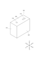
図2および図3に基づいて、印刷装置101の外観構成について説明する。なお、以下では、印刷装置101から見た方向を、各図に示したXYZ直交座標系による方向を用いて説明するが、これらの方向は説明の便宜上のものにすぎず、以下の実施形態を何ら限定するものではない。 The external configuration of the printing apparatus 101 will be described based on FIGS. 2 and 3. Note that the directions seen from the printing apparatus 101 will be explained below using the directions according to the XYZ orthogonal coordinate system shown in each figure, but these directions are only for convenience of explanation, and the following embodiments It is not limited in any way.

印刷装置101は、略直方体状に形成されている。印刷装置101の6つの外面のうち、後述するプリントボタン115が設けられた外面を第1外面103といい、第1外面103とは反対側の外面を第2外面105という。また、第1外面103或いは第2外面105を底面としたときに側面に相当する4つの外面のうち、面積の大きい2つの外面の一方を第3外面107といい、他方を第4外面109という。さらに、側面に相当する4つの外面のうち、面積の小さい2つの外面の一方を第5外面111といい、他方を第6外面113という。すなわち、第1外面103、第2外面105、第3外面107、第4外面109、第5外面111および第6外面113は、それぞれ、印刷装置101から見て、+Z方向、-Z方向、+X方向、-X方向、+Y方向および-Y方向に設けられている。 The printing device 101 is formed into a substantially rectangular parallelepiped shape. Among the six outer surfaces of the printing device 101, the outer surface on which a print button 115 (described later) is provided is referred to as a first outer surface 103, and the outer surface opposite to the first outer surface 103 is referred to as a second outer surface 105. Furthermore, among the four outer surfaces corresponding to side surfaces when the first outer surface 103 or the second outer surface 105 is the bottom surface, one of the two outer surfaces with a larger area is referred to as a third outer surface 107, and the other is referred to as a fourth outer surface 109. . Further, among the four outer surfaces corresponding to the side surfaces, one of the two smaller outer surfaces is referred to as a fifth outer surface 111 and the other is referred to as a sixth outer surface 113. That is, the first outer surface 103, the second outer surface 105, the third outer surface 107, the fourth outer surface 109, the fifth outer surface 111, and the sixth outer surface 113 are arranged in the +Z direction, the −Z direction, and the +X direction, respectively, when viewed from the printing device 101. direction, -X direction, +Y direction, and -Y direction.

印刷装置101の第1外面103には、プリントボタン115と、電源ボタン116とが設けられている。プリントボタン115は、「案内部」の一例である。 A print button 115 and a power button 116 are provided on the first outer surface 103 of the printing device 101 . The print button 115 is an example of a "guidance section."

プリントボタン115は、ユーザー301(図8参照)からの印刷開始指示を受け付ける。ユーザー301からの印刷開始指示は、例えばプリントボタン115が短押しされることにより行われる。プリントボタン115は、第1外面103の中央部に対して、+Y方向且つ+X方向寄りに設けられている。ユーザー301は、印刷装置101を媒体201上に置いた後、プリントボタン115を短押しし、把持した印刷装置101を媒体201の表面に沿ってフリーハンドで移動させることで、印刷装置101に印刷画像203(図8参照)を印刷させることができる。 The print button 115 accepts a print start instruction from the user 301 (see FIG. 8). The print start instruction from the user 301 is issued, for example, by briefly pressing the print button 115. The print button 115 is provided toward the center of the first outer surface 103 in the +Y direction and the +X direction. After placing the printing device 101 on the medium 201, the user 301 briefly presses the print button 115 and moves the gripped printing device 101 freehand along the surface of the medium 201 to print on the printing device 101. An image 203 (see FIG. 8) can be printed.

プリントボタン115は、LED(Light Emitting Diode)が組み込まれている。プリントボタン115は、LEDを点滅させることにより、後述するエラー通知を行う。また、プリントボタン115は、ユーザー301からの印刷中止指示を受け付ける。ユーザー301からの印刷中止指示は、例えばプリントボタン115が長押しされることにより行われる。 The print button 115 has a built-in LED (Light Emitting Diode). The print button 115 sends an error notification, which will be described later, by blinking the LED. Further, the print button 115 accepts a print cancellation instruction from the user 301. The user 301 instructs to cancel printing by, for example, pressing and holding the print button 115.

電源ボタン116は、ユーザー301からの電源のON/OFFの切替え指示を受け付ける。電源ボタン116は、第1外面103の中央部に対して、-Y方向寄りに設けられている。 The power button 116 receives an instruction from the user 301 to turn the power ON/OFF. The power button 116 is provided toward the center of the first outer surface 103 in the −Y direction.

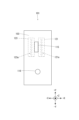
図3に示すように、印刷装置101の第2外面105には、第1ローラーユニット117と、第2ローラーユニット119と、第1印刷ヘッド121と、第2印刷ヘッド123と、移動検出センサー125と、スペーサー部材検出部163とが設けられている。第1ローラーユニット117および第2ローラーユニット119は、「規制部材」の一例である。また、第1印刷ヘッド121は、「第1吐出部」の一例であり、第2印刷ヘッド123は、「第2吐出部」の一例である。また、移動検出センサー125は、「移動検出部」の一例である。 As shown in FIG. 3, the second outer surface 105 of the printing device 101 includes a first roller unit 117, a second roller unit 119, a first print head 121, a second print head 123, and a movement detection sensor 125. and a spacer member detection section 163 are provided. The first roller unit 117 and the second roller unit 119 are an example of a "regulating member." Further, the first print head 121 is an example of a "first ejection section", and the second print head 123 is an example of a "second ejection section". Furthermore, the movement detection sensor 125 is an example of a "movement detection section."

第1ローラーユニット117は、第2外面105の+X方向の端部に取り付けられる。第1ローラーユニット117は、第1軸部材117aと、第1軸部材117aの+Y方向端部に固定された第1前側ローラー117bと、第1軸部材117aの-Y方向端部に固定された第1後側ローラー117cとを有する。第1ローラーユニット117は、第1軸部材117aが不図示の滑り軸受けに係合することで、滑り軸受けに回転可能に保持される。 The first roller unit 117 is attached to the end of the second outer surface 105 in the +X direction. The first roller unit 117 includes a first shaft member 117a, a first front roller 117b fixed to the +Y direction end of the first shaft member 117a, and a first front roller 117b fixed to the −Y direction end of the first shaft member 117a. It has a first rear roller 117c. The first roller unit 117 is rotatably held by the sliding bearing (not shown) by the first shaft member 117a engaging with the sliding bearing.

また、第2ローラーユニット119は、第2外面105の-X方向の端部に取り付けられる。第2ローラーユニット119は、第2軸部材119aと、第2軸部材119aの+Y方向端部に固定された第2前側ローラー119bと、第2軸部材119aの-Y方向端部に固定された第2後側ローラー119cとを有する。第2ローラーユニット119は、第2軸部材119aが不図示の滑り軸受けに係合することで、滑り軸受けに回転可能に保持される。 Further, the second roller unit 119 is attached to the end of the second outer surface 105 in the -X direction. The second roller unit 119 includes a second shaft member 119a, a second front roller 119b fixed to the +Y direction end of the second shaft member 119a, and a second front roller 119b fixed to the −Y direction end of the second shaft member 119a. It has a second rear roller 119c. The second roller unit 119 is rotatably held by the sliding bearing (not shown) by the second shaft member 119a engaging with the sliding bearing.

印刷装置101の第2外面105は、スペーサー部材151が着脱可能に構成されている。スペーサー部材151は、「解除部材」の一例である。スペーサー部材151は、略矩形の板状に構成された部材であり、第2外面105に対し、着脱可能に構成される。また、スペーサー部材151は、スペーサー部材四つのローラー切り欠き部153と、ヘッド切り欠き部155と、センサー切り欠き部157と、四つの第1突起159とを有する。 The second outer surface 105 of the printing device 101 is configured such that a spacer member 151 is removably attached thereto. The spacer member 151 is an example of a "release member". The spacer member 151 is a substantially rectangular plate-shaped member, and is configured to be attachable to and detachable from the second outer surface 105. Further, the spacer member 151 has four roller notches 153, a head notch 155, a sensor notch 157, and four first protrusions 159.

四つのローラー切り欠き部153は、スペーサー部材151が印刷装置101の第2外面105に装着されたとき、第1前側ローラー117b、第1後側ローラー117c、第2前側ローラー119bおよび第2後側ローラー119cに対応する位置に設けられている。また、ヘッド切り欠き部155は、スペーサー部材151が印刷装置101の第2外面105に装着されたとき、第1印刷ヘッド121および第2印刷ヘッド123に対応する位置に設けられている。また、センサー切り欠き部157は、スペーサー部材151が印刷装置101の第2外面105に装着されたとき、移動検出センサー125に対応する位置に設けられている。 When the spacer member 151 is attached to the second outer surface 105 of the printing device 101, the four roller notches 153 are arranged so that when the spacer member 151 is attached to the second outer surface 105 of the printing device 101, the first front roller 117b, first rear roller 117c, second front roller 119b, and second rear roller It is provided at a position corresponding to the roller 119c. Further, the head cutout portion 155 is provided at a position corresponding to the first print head 121 and the second print head 123 when the spacer member 151 is attached to the second outer surface 105 of the printing device 101. Further, the sensor cutout portion 157 is provided at a position corresponding to the movement detection sensor 125 when the spacer member 151 is attached to the second outer surface 105 of the printing device 101.

四つの第1突起159のうち二つの突起は、ヘッド切り欠き部155の-Y方向寄りの位置に、X方向に相互に離れて設けられている。また、四つの第1突起159のうち残りの二つの突起は、四つのローラー切り欠き部153のうち、第1後側ローラー117cおよび第2後側ローラー119cに対応する二つのローラー切り欠き部153の+Y方向寄りの位置に、X方向に相互に離れて設けられている。 Two of the four first protrusions 159 are provided at positions closer to the −Y direction of the head notch 155 and spaced apart from each other in the X direction. In addition, the remaining two protrusions among the four first protrusions 159 are connected to the two roller notches 153 corresponding to the first rear roller 117c and the second rear roller 119c among the four roller notches 153. They are provided at positions closer to the +Y direction and spaced apart from each other in the X direction.

スペーサー部材151が印刷装置101に装着されたとき、四つの第1突起159の表面は、第1ローラーユニット117および第2ローラーユニット119の各ローラーの表面よりも第2外面105に対して遠い位置にある。このため、スペーサー部材151が装着された印刷装置101が媒体201の上に置かれると、四つの第1突起159が媒体201に接することにより、各ローラーが媒体201の表面から浮いた状態となる。これにより、スペーサー部材151が装着された印刷装置101は、媒体201上を滑るように移動させることができる。 When the spacer member 151 is attached to the printing device 101, the surfaces of the four first protrusions 159 are located further away from the second outer surface 105 than the surfaces of the respective rollers of the first roller unit 117 and the second roller unit 119. It is in. Therefore, when the printing device 101 with the spacer member 151 attached is placed on the medium 201, the four first protrusions 159 come into contact with the medium 201, so that each roller is suspended from the surface of the medium 201. . Thereby, the printing apparatus 101 equipped with the spacer member 151 can be slidably moved on the medium 201.

第1ローラーユニット117および第2ローラーユニット119は、印刷装置101のX方向への直進走行性を高めるためのものである。X方向は、「第1方向」の一例である。例えば、第1ローラーユニット117は、第1軸部材117aに固定された第1前側ローラー117bと第1後側ローラー117cとが一体的に回転する。これにより、各ローラーが同じ方向且つ同じ線速で回転するため、媒体201に対する印刷装置101のX方向への移動をガイドすることができる。第2ローラーユニット119についても同様である。 The first roller unit 117 and the second roller unit 119 are for improving the straight running performance of the printing apparatus 101 in the X direction. The X direction is an example of a "first direction." For example, in the first roller unit 117, a first front roller 117b and a first rear roller 117c, which are fixed to a first shaft member 117a, rotate integrally. As a result, each roller rotates in the same direction and at the same linear speed, so that it is possible to guide the movement of the printing apparatus 101 in the X direction relative to the medium 201. The same applies to the second roller unit 119.

一方、スペーサー部材151は、印刷装置101の湾曲走行性を実現するためのものである。上述したように、印刷装置101の第2外面105にスペーサー部材151が装着されると、第1ローラーユニット117および第2ローラーユニット119の各ローラーが媒体201に対して非接触状態となり、直進走行性を実現できない状態となる。このように、第1ローラーユニット117および第2ローラーユニット119が、印刷装置101がX方向以外に移動されないように規制する規制部材として機能するのに対し、スペーサー部材151は、規制部材による規制を解除するための解除部材として機能する。 On the other hand, the spacer member 151 is for realizing curved running performance of the printing apparatus 101. As described above, when the spacer member 151 is attached to the second outer surface 105 of the printing device 101, each roller of the first roller unit 117 and the second roller unit 119 is in a non-contact state with respect to the medium 201, and the medium 201 is not moved straight. It becomes a state where one cannot realize one's sexuality. In this way, the first roller unit 117 and the second roller unit 119 function as regulating members that prevent the printing device 101 from moving in directions other than the Functions as a release member for release.

以下、印刷装置101にスペーサー部材151が装着されている状態で印刷装置101が動作するモードを、「第1モード」という。図4に示すように、印刷装置101は、第1モードで動作する場合、X方向のみならず、X方向に対して斜めの方向やX方向に対して直交する方向への移動も可能である。 Hereinafter, the mode in which the printing apparatus 101 operates with the spacer member 151 attached to the printing apparatus 101 will be referred to as a "first mode." As shown in FIG. 4, when operating in the first mode, the printing apparatus 101 can move not only in the X direction but also in directions diagonal to the X direction and directions perpendicular to the X direction. .

また、印刷装置101にスペーサー部材151が装着されていない状態で印刷装置101が動作するモードを、「第2モード」という。図5に示すように、印刷装置101は、第2モードで動作する場合、X方向の移動が可能であり、X方向に対して斜めの方向やX方向に対して直交する方向への移動が規制される。 Furthermore, a mode in which the printing apparatus 101 operates without the spacer member 151 attached to the printing apparatus 101 is referred to as a "second mode." As shown in FIG. 5, when operating in the second mode, the printing apparatus 101 can move in the X direction, and can also move in a direction diagonal to the X direction or in a direction perpendicular to the X direction. Regulated.

図3の説明に戻る。第1印刷ヘッド121および第2印刷ヘッド123は、各ノズルからインクを吐出することで、媒体201に印刷画像203を印刷する。第1印刷ヘッド121および第2印刷ヘッド123は、第2外面105の中央部に対して、+Y方向寄りに設けられている。また、第1印刷ヘッド121は、第2印刷ヘッド123の+X方向に設けられている。 Returning to the explanation of FIG. 3. The first print head 121 and the second print head 123 print the print image 203 on the medium 201 by ejecting ink from each nozzle. The first print head 121 and the second print head 123 are provided toward the center of the second outer surface 105 in the +Y direction. Further, the first print head 121 is provided in the +X direction of the second print head 123.

移動検出センサー125は、印刷装置101が媒体201に対して移動させられる間に、印刷装置101のX方向およびY方向における移動量を検出する。移動検出センサー125は、第1印刷ヘッド121および第2印刷ヘッド123に対して、-Y方向に設けられている。 The movement detection sensor 125 detects the amount of movement of the printing device 101 in the X direction and the Y direction while the printing device 101 is moved relative to the medium 201. The movement detection sensor 125 is provided in the −Y direction with respect to the first print head 121 and the second print head 123.

スペーサー部材検出部163は、スペーサー部材151の装着の有無を検出する。スペーサー部材検出部163は、移動検出センサー125に対して、-Y方向に設けられている。 The spacer member detection unit 163 detects whether or not the spacer member 151 is attached. The spacer member detection unit 163 is provided in the -Y direction with respect to the movement detection sensor 125.

第1印刷ヘッド121は、第1ノズル列121aを備えたインクジェットヘッドである。また、第2印刷ヘッド123は、第2ノズル列123aを備えたインクジェットヘッドである。第1ノズル列121aおよび第2ノズル列123aは、Y方向に沿って複数のノズルが平行に配列されており、X方向において相互に離れて設けられている。また、第1ノズル列121aおよび第2ノズル列123aは、ノズル数およびノズル間隔が同じであり、第2外面105のY方向において同じ位置に配置されている。 The first print head 121 is an inkjet head including a first nozzle row 121a. Further, the second print head 123 is an inkjet head including a second nozzle row 123a. In the first nozzle row 121a and the second nozzle row 123a, a plurality of nozzles are arranged in parallel along the Y direction, and are provided apart from each other in the X direction. Further, the first nozzle row 121a and the second nozzle row 123a have the same number of nozzles and the same nozzle interval, and are arranged at the same position on the second outer surface 105 in the Y direction.

なお、第1ノズル列121aおよび第2ノズル列123aは、Y方向に平行に設けられているとしたが、「平行」とは、厳密な意味の平行のみを意味するものではなく、本実施形態が属する技術分野において許容される誤差の範囲を含むものである。また、第1ノズル列121aおよび第2ノズル列123aは、Y方向と直交するX方向において相互に離れて設けられているとしたが、「直交」とは、厳密な意味の直交のみを意味するものではなく、本実施形態が属する技術分野において許容される誤差の範囲を含むものである。 Although the first nozzle row 121a and the second nozzle row 123a are provided parallel to the Y direction, "parallel" does not mean only parallel in a strict sense; It includes the range of error allowed in the technical field to which it belongs. Furthermore, although the first nozzle row 121a and the second nozzle row 123a are provided apart from each other in the X direction orthogonal to the Y direction, "orthogonal" only means orthogonal in the strict sense. Rather, it includes the range of error allowed in the technical field to which this embodiment belongs.

なお、第1ノズル列121aのノズルから吐出されるインクと、第2ノズル列123aのノズルから吐出されるインクは同じインクでもよいし、異なるインクでもよいが、以下の説明では、第1ノズル列121aのノズルから黒色インクを吐出し、第2ノズル列123aのノズルから赤色インクを吐出するものとする。つまり、本実施形態の印刷装置101は、第1印刷ヘッド121および第2印刷ヘッド123を用いて印刷を行うことで多色印刷を実現し、第1印刷ヘッド121のみを用いて印刷を行うことで黒色の単色印刷を実現する。なお、黒色インクは、「第1液体」の一例であり、赤色インクは、「第2液体」の一例である。 Note that the ink ejected from the nozzles of the first nozzle row 121a and the ink ejected from the nozzles of the second nozzle row 123a may be the same ink or different inks, but in the following description, the ink ejected from the nozzles of the first nozzle row It is assumed that black ink is ejected from the nozzles 121a and red ink is ejected from the nozzles of the second nozzle row 123a. That is, the printing apparatus 101 of this embodiment realizes multicolor printing by printing using the first print head 121 and the second print head 123, and prints using only the first print head 121. Achieves monochromatic black printing. Note that black ink is an example of a "first liquid" and red ink is an example of a "second liquid."

図6および図7に示すように、第1印刷ヘッド121は、X方向において第2印刷ヘッド123より印刷装置101の中央寄りに設けられている。つまり、第2外面105のX方向における中央位置C1と第1印刷ヘッド121の第1ノズル列121aとの間の距離である第1距離L1は、中央位置C1と第2印刷ヘッド123の第2ノズル列123aとの間の距離である第2距離L2より短い。 As shown in FIGS. 6 and 7, the first print head 121 is provided closer to the center of the printing apparatus 101 than the second print head 123 in the X direction. In other words, the first distance L1, which is the distance between the center position C1 of the second outer surface 105 in the X direction and the first nozzle row 121a of the first print head 121, is the distance between the center position C1 and the second This is shorter than the second distance L2, which is the distance from the nozzle row 123a.

また、第1印刷ヘッド121の+Z方向には、プリントボタン115が設けられている。すなわち、プリントボタン115は、第1外面103において第1印刷ヘッド121に対応する位置に設けられている。ここで、プリントボタン115が、第1印刷ヘッド121に対応する位置に設けられているとは、プリントボタン115が、X方向およびY方向において第1印刷ヘッド121の範囲内にあることを意味する。これにより、第1印刷ヘッド121が設けられている位置、すなわち第1印刷ヘッド121による印刷位置を、プリントボタン115によりユーザー301に示すことができる。また、印刷装置101は、黒色インクのみを使用した単色印刷と、黒色インクおよび赤色インクを使用した多色印刷とを行い得るものであるが、赤色インクより黒色インクの使用量が多くなると考えられるため、第2印刷ヘッド123ではなく第1印刷ヘッド121による印刷位置をユーザー301に示すことで、使い勝手を向上できる。 Further, a print button 115 is provided in the +Z direction of the first print head 121. That is, the print button 115 is provided at a position corresponding to the first print head 121 on the first outer surface 103. Here, the print button 115 being provided at a position corresponding to the first print head 121 means that the print button 115 is within the range of the first print head 121 in the X direction and the Y direction. . Thereby, the position where the first print head 121 is provided, that is, the printing position by the first print head 121 can be shown to the user 301 using the print button 115. Further, the printing device 101 can perform monochrome printing using only black ink and multicolor printing using black ink and red ink, but it is thought that the amount of black ink used will be greater than the amount of red ink. Therefore, by showing the user 301 the printing position by the first print head 121 instead of the second print head 123, usability can be improved.

また、図7に示すように、印刷装置101の内部には、黒インクカートリッジ131と、赤インクカートリッジ133とが装着される。黒インクカートリッジ131は、黒インクタンク127と、第1印刷ヘッド121とを備えている。第1印刷ヘッド121は、黒インクタンク127の-Z方向に設けられている。黒インクタンク127には、黒色インクが収容され、第1印刷ヘッド121に黒色インクを供給する。 Further, as shown in FIG. 7, a black ink cartridge 131 and a red ink cartridge 133 are installed inside the printing apparatus 101. The black ink cartridge 131 includes a black ink tank 127 and a first print head 121. The first print head 121 is provided in the -Z direction of the black ink tank 127. The black ink tank 127 stores black ink and supplies the black ink to the first print head 121 .

赤インクカートリッジ133は、赤インクタンク129と、第2印刷ヘッド123とを備えている。第2印刷ヘッド123は、赤インクタンク129の-Z方向に設けられている。赤インクタンク129には、赤色インクが収容され、第2印刷ヘッド123に赤色インクを供給する。 The red ink cartridge 133 includes a red ink tank 129 and a second print head 123. The second print head 123 is provided in the -Z direction of the red ink tank 129. The red ink tank 129 stores red ink and supplies the red ink to the second print head 123 .

黒インクカートリッジ131は、赤インクカートリッジ133の+X方向に設けられ、黒インクカートリッジ131のインク収容量は、赤インクカートリッジ133のインク収容量よりも多い。 The black ink cartridge 131 is provided in the +X direction of the red ink cartridge 133, and the ink capacity of the black ink cartridge 131 is larger than the ink capacity of the red ink cartridge 133.

上述したように、印刷装置101は、黒色インクが赤色インクに対して多く消費されると考えられるため、黒インクタンク127のインク貯留量は、赤インクタンク129のインク貯留量よりも多く設計されている。また、これに伴い、第2印刷ヘッド123を、第1印刷ヘッド121に比べて、第2外面105のX方向における中央位置C1から離れた位置に設けることで、赤インクタンク129の直下、すなわち赤インクタンク129の-Z方向に第2印刷ヘッド123を配置できる。これにより、赤インクタンク129から第2印刷ヘッド123への赤色インクの供給経路を短くすることができる。また、X方向において、第1印刷ヘッド121を、第2印刷ヘッド123と極力近くなるように配置しても、黒インクタンク127の直下に第1印刷ヘッド121を配置できるため、黒インクタンク127から第1印刷ヘッド121への黒色インクの供給経路も短くすることができる。 As described above, in the printing apparatus 101, the amount of ink stored in the black ink tank 127 is designed to be larger than the amount of ink stored in the red ink tank 129, since black ink is considered to be consumed more than red ink. ing. Further, in accordance with this, by providing the second print head 123 at a position farther from the center position C1 of the second outer surface 105 in the The second print head 123 can be arranged in the -Z direction of the red ink tank 129. This allows the red ink supply path from the red ink tank 129 to the second print head 123 to be shortened. Further, even if the first print head 121 is arranged as close as possible to the second print head 123 in the X direction, the first print head 121 can be arranged directly below the black ink tank 127. The supply path of the black ink from the to the first print head 121 can also be shortened.

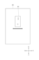
図8に示すように、印刷装置101は、印刷装置101が印刷装置101から見て+X方向に移動させられる間に、媒体201に印刷画像203を印刷可能である。また、印刷装置101は、印刷装置101が印刷装置101から見て-X方向に移動させられる間に、媒体201に印刷画像203を印刷することも可能である。ここで、印刷装置101が印刷装置101から見て+X方向に移動させられるとは、第3外面107が先方となるように印刷装置101が移動させられることを意味する。また、印刷装置101が印刷装置101から見て-X方向に移動させられるとは、第4外面109が先方となるように印刷装置101が移動させられることを意味する。 As shown in FIG. 8, the printing device 101 can print the print image 203 on the medium 201 while the printing device 101 is moved in the +X direction as viewed from the printing device 101. The printing device 101 can also print the print image 203 on the medium 201 while the printing device 101 is moved in the -X direction as seen from the printing device 101. Here, when the printing device 101 is moved in the +X direction as viewed from the printing device 101, it means that the printing device 101 is moved so that the third outer surface 107 faces forward. Further, when the printing device 101 is moved in the -X direction as viewed from the printing device 101, it means that the printing device 101 is moved so that the fourth outer surface 109 is facing forward.

また、印刷装置101は、1つの印刷ジョブを1回のパスで実行できない場合、複数回のパスに分けて実行することができる。ここで、パスとは、+X方向或いは-X方向の一方向に印刷装置101が移動させられる間に行われる印刷動作を指す。 Furthermore, if the printing apparatus 101 cannot execute one print job in one pass, it can divide it into multiple passes and execute it. Here, a pass refers to a printing operation performed while the printing apparatus 101 is moved in one direction, the +X direction or the -X direction.

このように、1つの印刷ジョブを複数回のパスに分けて実行する場合、ユーザー301は、情報処理装置1において、移動方向として、一方向印刷および二方向印刷のいずれかを選択できる。例えば、一方向印刷が選択された場合、印刷装置101は、+X方向に移動しながら1パス分の印刷を行った後、-X方向且つ-Y方向への改行を行う、といった動作を繰り返す。一方、二方向印刷が選択された場合、印刷装置101は、+X方向に移動しながら1パス分の印刷を行った後、-Y方向への改行を行い、-X方向に移動しながら次のパスの印刷を行った後、-Y方向への改行を行う、といった動作を繰り返す。 In this way, when executing one print job in multiple passes, the user 301 can select either unidirectional printing or bidirectional printing as the direction of movement in the information processing apparatus 1. For example, when unidirectional printing is selected, the printing apparatus 101 repeats operations such as printing one pass while moving in the +X direction, and then performing a line feed in the -X and -Y directions. On the other hand, when bidirectional printing is selected, the printing device 101 prints one pass while moving in the +X direction, then prints a line in the -Y direction, and prints the next pass while moving in the -X direction. After printing the path, repeat the operation of starting a line in the -Y direction.

また、印刷ジョブは、パスごとに印刷装置101の移動方向を指定している。以下、印刷ジョブをパス単位に分割したものを「パス単位ジョブ」という。例えば、一方向印刷では、全てのパス単位ジョブについて、指定方向が+X方向に指定されている。また、二方向印刷では、奇数番目のパス単位ジョブについて、指定方向が+X方向に指定され、偶数番目のパス単位ジョブについて、指定方向が-X方向に指定されている。 Furthermore, the print job specifies the moving direction of the printing apparatus 101 for each pass. Hereinafter, a print job divided into passes will be referred to as a "pass unit job." For example, in unidirectional printing, the designated direction is the +X direction for all pass unit jobs. Furthermore, in bidirectional printing, the designated direction is designated as +X direction for odd-numbered pass unit jobs, and the designated direction is designated as -X direction for even-numbered pass unit jobs.

また、パス単位ジョブに含まれる印刷データは、指定された印刷装置101の移動方向に対応している。例えば、指定方向が+X方向に指定されているパス単位ジョブは、印刷装置101が+X方向に移動されたときに適切な印刷画像203が印刷される印刷データを含む。また、指定方向が-X方向に指定されているパス単位ジョブは、印刷装置101が-X方向に移動されたときに適切な印刷画像203が印刷される印刷データを含む。 Further, the print data included in the pass unit job corresponds to the specified movement direction of the printing apparatus 101. For example, a pass unit job whose designated direction is +X direction includes print data in which an appropriate print image 203 is printed when the printing apparatus 101 is moved in the +X direction. Further, a pass unit job whose designated direction is the -X direction includes print data in which an appropriate print image 203 is printed when the printing apparatus 101 is moved in the -X direction.

図9を参照し、印刷システムSYのハードウェア構成について説明する。印刷システムSYは、情報処理装置1と、印刷装置101とを備えている。情報処理装置1は、操作・表示部11と、処理装置側通信部13と、処理装置側制御部15とを備えている。 Referring to FIG. 9, the hardware configuration of the printing system SY will be described. The printing system SY includes an information processing device 1 and a printing device 101. The information processing device 1 includes an operation/display section 11, a processing device side communication section 13, and a processing device side control section 15.

操作・表示部11は、例えばタッチパネルであり、ユーザー301による各種操作および各種情報の表示に用いられる。操作・表示部11は、例えば、印刷指示画面21(図10参照)や印刷設定画面31(図11参照)を表示する。 The operation/display unit 11 is, for example, a touch panel, and is used for various operations by the user 301 and for displaying various information. The operation/display unit 11 displays, for example, a print instruction screen 21 (see FIG. 10) and a print setting screen 31 (see FIG. 11).

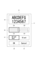
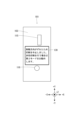
ここで、印刷指示画面21および印刷設定画面31について説明する。図10に示すように、印刷指示画面21には、印刷種別選択欄23と、情報入力欄25と、第1OKボタン27と、第1キャンセルボタン29とが設けられる。 Here, the print instruction screen 21 and print setting screen 31 will be explained. As shown in FIG. 10, the print instruction screen 21 is provided with a print type selection field 23, an information input field 25, a first OK button 27, and a first cancel button 29.

印刷種別選択欄23には、テキスト選択肢23aと、イメージ選択肢23bとが選択可能に表示される。印刷種別選択欄23においてテキスト選択肢23aが選択された場合、情報入力欄25には、テキストが入力される。なお、テキストとは、不図示のソフトウェアキーボードから入力された文字、数字、記号および絵文字等であり、テキストコードが付与された情報を指す。また、印刷種別選択欄23においてイメージ選択肢23bが選択された場合、情報入力欄25には、イメージが描画または挿入される。なお、イメージとは、テキストコードが付与されていない情報を指す。 In the print type selection field 23, a text option 23a and an image option 23b are selectably displayed. When the text option 23a is selected in the print type selection field 23, text is input into the information input field 25. Note that the text refers to characters, numbers, symbols, pictographs, etc. input from a software keyboard (not shown), and refers to information to which a text code is attached. Further, when the image option 23b is selected in the print type selection field 23, an image is drawn or inserted in the information input field 25. Note that an image refers to information to which no text code is attached.

情報入力欄25には、印刷種別選択欄23においてテキスト選択肢23aが選択された場合に入力されたテキストが表示される。また、情報入力欄25には、印刷種別選択欄23においてイメージ選択肢23bが選択された場合に描画または挿入されたイメージが表示される。 The information input field 25 displays the text that is input when the text option 23a is selected in the print type selection field 23. Further, the information input field 25 displays an image drawn or inserted when the image option 23b is selected in the print type selection field 23.

第1OKボタン27は、印刷指示画面21における情報入力を確定するための操作を受け付ける。情報処理装置1は、第1OKボタン27の操作を受け付けると、情報入力を確定し、印刷設定画面31を表示する。第1キャンセルボタン29は、印刷指示画面21における情報入力をキャンセルする操作を受け付ける。情報処理装置1は、第1キャンセルボタン29の操作を受け付けると、印刷指示画面21に入力された情報をリセットし、不図示の初期画面を表示させる。 The first OK button 27 accepts an operation for confirming information input on the print instruction screen 21. When the information processing device 1 receives the operation of the first OK button 27, the information processing device 1 confirms the information input and displays the print setting screen 31. The first cancel button 29 accepts an operation to cancel information input on the print instruction screen 21. When the information processing device 1 receives the operation of the first cancel button 29, it resets the information input to the print instruction screen 21 and displays an initial screen (not shown).

図11に示すように、印刷設定画面31には、印刷プレビュー33と、移動方向選択欄35と、印刷色選択欄37と、第2OKボタン39と、第2キャンセルボタン41とが設けられる。 As shown in FIG. 11, the print setting screen 31 is provided with a print preview 33, a movement direction selection field 35, a print color selection field 37, a second OK button 39, and a second cancel button 41.

印刷プレビュー33には、印刷指示画面21の情報入力欄25に入力された情報に基づいて、印刷画像203のプレビューが表示される。 The print preview 33 displays a preview of the print image 203 based on the information input in the information input field 25 of the print instruction screen 21.

移動方向選択欄35には、一方向印刷選択肢35aと、二方向印刷選択肢35bとが選択可能に表示される。なお、印刷画像203が1回のパスで実行できる場合には、一方向印刷選択肢35aのみを選択可能とし、二方向印刷選択肢35bを選択不能としてもよい。 In the movement direction selection field 35, a one-way printing option 35a and a two-way printing option 35b are selectably displayed. Note that if the print image 203 can be executed in one pass, only the one-way printing option 35a may be selectable, and the two-way printing option 35b may not be selectable.

印刷色選択欄37には、多色印刷選択肢37aと、単色印刷選択肢37bとが選択可能に表示される。情報処理装置1は、多色印刷選択肢37aが選択された場合、黒色および赤色で印刷画像203を印刷させる印刷データを生成する。また、情報処理装置1は、単色印刷選択肢37bが選択された場合、黒色のみで印刷画像203を印刷させる印刷データを生成する。以下、黒色および赤色で印刷画像203を印刷させる印刷データを、「多色印刷用印刷データ」という。また、黒色のみで印刷画像203を印刷させる印刷データを「単色印刷用印刷データ」という。 In the print color selection column 37, a multicolor print option 37a and a single color print option 37b are selectably displayed. When the multicolor printing option 37a is selected, the information processing device 1 generates print data for printing the print image 203 in black and red. Furthermore, when the monochrome printing option 37b is selected, the information processing device 1 generates print data that causes the print image 203 to be printed only in black. Hereinafter, print data for printing the print image 203 in black and red will be referred to as "print data for multicolor printing." Furthermore, print data for printing the print image 203 only in black is referred to as "print data for monochrome printing."

なお、情報処理装置1は、印刷指示画面21の情報入力欄25に入力された情報に基づいて印刷データを生成するが、入力された情報がカラーのテキストまたはイメージを示す情報である場合、所定の色変換処理を行うことにより、黒色と赤色の二色の印刷データ、或いは黒色一色の印刷データを生成する。 Note that the information processing device 1 generates print data based on the information input in the information input field 25 of the print instruction screen 21, but if the input information is information indicating color text or an image, a predetermined By performing the color conversion process, two-color print data of black and red, or one-color black print data is generated.

第2OKボタン39は、印刷設定画面31における選択を確定するための操作を受け付ける。情報処理装置1は、第2OKボタン39の操作を受け付けると、印刷データを生成し、生成した印刷データと、印刷種別を示す情報と、指定方向を示す情報とを含む印刷ジョブを印刷装置101に送信する。第2キャンセルボタン41は、印刷設定画面31における選択をキャンセルする操作を受け付ける。情報処理装置1は、第2キャンセルボタン41の操作を受け付けると、印刷設定画面31の設定をリセットし、印刷指示画面21を表示させる。 The second OK button 39 accepts an operation for confirming a selection on the print setting screen 31. Upon receiving the operation of the second OK button 39, the information processing device 1 generates print data, and sends a print job including the generated print data, information indicating the print type, and information indicating the specified direction to the printing device 101. Send. The second cancel button 41 accepts an operation to cancel the selection on the print setting screen 31. When the information processing device 1 receives the operation of the second cancel button 41, it resets the settings on the print setting screen 31 and displays the print instruction screen 21.

図9の説明に戻る。処理装置側通信部13は、無線等を介して、印刷装置101と通信する。例えば、処理装置側通信部13は、印刷装置101に印刷ジョブを送信する。 Returning to the explanation of FIG. 9. The processing device side communication unit 13 communicates with the printing device 101 via wireless or the like. For example, the processing device side communication unit 13 transmits a print job to the printing device 101.

処理装置側制御部15は、処理装置側CPU(Central Processing Unit)16と、処理装置側ROM(Read Only Memory)17と、処理装置側RAM(Random Access Memory)18とを含む。 The processing device side control unit 15 includes a processing device side CPU (Central Processing Unit) 16, a processing device side ROM (Read Only Memory) 17, and a processing device side RAM (Random Access Memory) 18.

処理装置側CPU16は、処理装置側ROM17に記憶された各種制御プログラムを処理装置側RAM18に展開して実行することにより、各種制御を行う。なお、処理装置側制御部15は、処理装置側CPU16に代え、ASIC(Application Specific Integrated Circuit)等のハードウェア回路をプロセッサーとして用いてもよい。また、プロセッサーは、1以上のCPUとASIC等のハードウェア回路が協働して動作する構成でもよい。 The processing device side CPU 16 performs various controls by loading various control programs stored in the processing device side ROM 17 into the processing device side RAM 18 and executing them. Note that the processing device side control unit 15 may use a hardware circuit such as an ASIC (Application Specific Integrated Circuit) as a processor instead of the processing device side CPU 16. Further, the processor may have a configuration in which one or more CPUs and a hardware circuit such as an ASIC work together.

処理装置側ROM17は、フラッシュメモリーなどの書き換え可能なROMであり、各種制御プログラムおよび各種制御データを記憶する。処理装置側RAM18は、処理装置側CPU16が各種制御を行うためのワークエリアとして用いられる。 The processing device side ROM 17 is a rewritable ROM such as a flash memory, and stores various control programs and various control data. The processing device side RAM 18 is used as a work area for the processing device side CPU 16 to perform various controls.

処理装置側ROM17は、印刷装置101を制御するための専用アプリケーション17aを記憶する。処理装置側CPU16は、専用アプリケーション17aを用いて、上記の印刷指示画面21および印刷設定画面31を表示する。 The processing device side ROM 17 stores a dedicated application 17a for controlling the printing device 101. The processing device side CPU 16 displays the above print instruction screen 21 and print setting screen 31 using the dedicated application 17a.

また、処理装置側CPU16は、専用アプリケーション17aを用いて、印刷ジョブを生成する。より具体的には、処理装置側CPU16は、印刷指示画面21において入力された情報と、印刷設定画面31の設定とに基づいて、印刷ジョブを生成する。 Further, the processing device side CPU 16 generates a print job using the dedicated application 17a. More specifically, the processing device side CPU 16 generates a print job based on the information input on the print instruction screen 21 and the settings on the print setting screen 31.

印刷装置101は、印刷装置側通信部161と、移動検出センサー125と、第1印刷ヘッド121と、第2印刷ヘッド123と、スペーサー部材検出部163と、印刷装置側制御部165とを備えている。スペーサー部材検出部163は、「第1装着検出部」の一例である。 The printing device 101 includes a printing device side communication section 161, a movement detection sensor 125, a first print head 121, a second print head 123, a spacer member detection section 163, and a printing device side control section 165. There is. The spacer member detection unit 163 is an example of a “first attachment detection unit”.

印刷装置側通信部161は、無線等を介して、情報処理装置1と通信する。 The printing device side communication unit 161 communicates with the information processing device 1 via wireless or the like.

移動検出センサー125は、印刷装置101が媒体201に対して移動させられる間に、媒体201の微小な凹凸を光学的に読み取り、移動検出信号を出力する。 The movement detection sensor 125 optically reads minute irregularities on the medium 201 while the printing apparatus 101 is moved relative to the medium 201, and outputs a movement detection signal.

第1印刷ヘッド121は、複数のノズルが配列された第1ノズル列121aを有する。第1印刷ヘッド121は、複数のノズルから黒色インクを吐出することにより媒体201に印刷を行う。 The first print head 121 has a first nozzle row 121a in which a plurality of nozzles are arranged. The first print head 121 prints on the medium 201 by ejecting black ink from a plurality of nozzles.

第2印刷ヘッド123は、複数のノズルが配列された第2ノズル列123aを有する。第2印刷ヘッド123は、複数のノズルから赤色インクを吐出することにより媒体201に印刷を行う。 The second print head 123 has a second nozzle row 123a in which a plurality of nozzles are arranged. The second print head 123 prints on the medium 201 by ejecting red ink from a plurality of nozzles.

スペーサー部材検出部163は、印刷装置101の第2外面105にスペーサー部材151が装着されているか否かを検出する。スペーサー部材検出部163は、第2外面105から突出して設けられ、スペーサー部材151が装着されたときに第2外面105に没入する物理スイッチにより構成される。スペーサー部材検出部163は、スペーサー部材151の装着を検出した場合、スペーサー部材151の装着を示す所定の信号を出力する。 The spacer member detection unit 163 detects whether the spacer member 151 is attached to the second outer surface 105 of the printing device 101. The spacer member detection unit 163 is formed by a physical switch that is provided to protrude from the second outer surface 105 and is recessed into the second outer surface 105 when the spacer member 151 is attached. When the spacer member detection unit 163 detects that the spacer member 151 is attached, it outputs a predetermined signal indicating that the spacer member 151 is attached.

印刷装置側制御部165は、印刷装置側CPU166と、印刷装置側ROM167と、印刷装置側RAM168とを含む。 The printing device side control unit 165 includes a printing device side CPU 166, a printing device side ROM 167, and a printing device side RAM 168.

印刷装置側CPU166は、印刷装置側ROM167に記憶された各種制御プログラムを印刷装置側RAM168に展開して実行することにより、各種制御を行う。なお、印刷装置側制御部165は、印刷装置側CPU166に代え、ASIC(Application Specific Integrated Circuit)等のハードウェア回路をプロセッサーとして用いてもよい。また、プロセッサーは、1以上のCPUとASIC等のハードウェア回路が協働して動作する構成でもよい。 The printing device side CPU 166 performs various controls by loading various control programs stored in the printing device side ROM 167 into the printing device side RAM 168 and executing them. Note that the printing device side control unit 165 may use a hardware circuit such as an ASIC (Application Specific Integrated Circuit) as a processor instead of the printing device side CPU 166. Further, the processor may have a configuration in which one or more CPUs and a hardware circuit such as an ASIC work together.

印刷装置側ROM167は、各種制御プログラムおよび各種制御データを記憶する。印刷装置側RAM168は、印刷装置側CPU166が各種制御を行うためのワークエリアとして用いられる。 The printing device side ROM 167 stores various control programs and various control data. The printing device side RAM 168 is used as a work area for the printing device side CPU 166 to perform various controls.

印刷装置側CPU166は、移動検出センサー125から出力された移動検出信号に基づいて、印刷装置101のX方向およびY方向の移動距離を算出する。また、印刷装置側CPU166は、算出したX方向およびY方向における移動距離に基づいて、第1印刷ヘッド121および第2印刷ヘッド123を制御し、媒体201に印刷画像203を印刷させる。より具体的には、印刷装置側CPU166は、算出したX方向における移動距離に基づくタイミングで、第1印刷ヘッド121および第2印刷ヘッド123の各ノズルからインクを吐出する。これにより、印刷装置101は、ユーザー301が印刷装置101をX方向に移動させる速度によらず、媒体201に印刷画像203を適切に印刷することができる。 The printing device side CPU 166 calculates the moving distance of the printing device 101 in the X direction and the Y direction based on the movement detection signal output from the movement detection sensor 125. Further, the printing device side CPU 166 controls the first print head 121 and the second print head 123 based on the calculated movement distances in the X direction and the Y direction, and causes the print image 203 to be printed on the medium 201. More specifically, the printing apparatus side CPU 166 ejects ink from each nozzle of the first print head 121 and the second print head 123 at a timing based on the calculated movement distance in the X direction. Thereby, the printing apparatus 101 can appropriately print the print image 203 on the medium 201 regardless of the speed at which the user 301 moves the printing apparatus 101 in the X direction.

また、印刷装置側CPU166は、スペーサー部材検出部163から、スペーサー部材151の装着を示す所定の信号を取得した場合、印刷装置101が第1モードで動作すると判断し、所定の信号を取得しない場合、印刷装置101が第2モードで動作すると判断する。 Further, when the printing apparatus side CPU 166 acquires a predetermined signal indicating attachment of the spacer member 151 from the spacer member detection unit 163, the printing apparatus side CPU 166 determines that the printing apparatus 101 operates in the first mode, and when the predetermined signal is not acquired. , it is determined that the printing device 101 operates in the second mode.

ところで、上述したように第1モードでは、印刷装置101がX方向に対し斜めの方向に移動させられる可能性がある。図12は、印刷装置101がX方向に移動させられながら多色印刷を行う場合と、X方向に対し斜めの方向に移動させられながら多色印刷を行う場合とを比較する図である。上述したように、印刷装置101に設けられた2つのノズル列である第1ノズル列121aと第2ノズル列123aは、X方向に相互に離れて設けられている。 By the way, as described above, in the first mode, there is a possibility that the printing apparatus 101 is moved in a direction diagonal to the X direction. FIG. 12 is a diagram comparing the case where the printing apparatus 101 performs multicolor printing while being moved in the X direction, and the case where the printing apparatus 101 performs multicolor printing while being moved in a direction diagonal to the X direction. As described above, the two nozzle rows provided in the printing apparatus 101, the first nozzle row 121a and the second nozzle row 123a, are provided apart from each other in the X direction.

仮に、第1移動軌跡T1に示したように、印刷装置101がX方向に沿って移動させられた場合、第1ノズル列121aのノズルから吐出された黒色インクの着弾により描画される黒色印刷画像203Bと、第2ノズル列123aのノズルから吐出された赤色インクの着弾により描画される赤色印刷画像203RとにY方向の位置ずれは生じない。ここで、黒色印刷画像203Bおよび赤色印刷画像203Rは、X方向およびY方向において同位置に印刷される印刷画像203である。同図では、便宜上、黒色印刷画像203Bと赤色印刷画像203Rとを、X方向に位置ずれして示している。 If the printing device 101 is moved along the X direction as shown in the first movement trajectory T1, a black print image is drawn by landing of black ink ejected from the nozzles of the first nozzle row 121a. 203B and the red printed image 203R drawn by the landing of red ink ejected from the nozzles of the second nozzle row 123a, no positional shift occurs in the Y direction. Here, the black print image 203B and the red print image 203R are print images 203 printed at the same position in the X direction and the Y direction. In the figure, for convenience, the black print image 203B and the red print image 203R are shown shifted in the X direction.

一方、第2移動軌跡T2に示したように、印刷装置101がX方向に対して斜めの方向に移動させられた場合、黒色印刷画像203Bと、赤色印刷画像203RとがY方向に位置ずれしてしまう。これは、第1ノズル列121aと第2ノズル列123aが、X方向に相互に離れて設けられていることに起因するものである。 On the other hand, as shown in the second movement trajectory T2, when the printing device 101 is moved in a direction diagonal to the X direction, the black print image 203B and the red print image 203R are misaligned in the Y direction. It ends up. This is due to the fact that the first nozzle row 121a and the second nozzle row 123a are provided apart from each other in the X direction.

本実施形態の印刷装置101は、この問題を解決するため、第1モードで動作する場合、且つ、多色印刷を行う場合、印刷装置101の移動方向が、X方向から閾値以上の角度でずれたときにエラー処理を行う。つまり、印刷装置101は、印刷装置101が手動で移動させられた場合の印刷装置101のX方向に対する移動方向の角度θが閾値以上となったとき、エラー処理を行う。 In order to solve this problem, the printing apparatus 101 of the present embodiment has a configuration in which, when operating in the first mode and performing multicolor printing, the moving direction of the printing apparatus 101 deviates from the X direction by an angle equal to or more than a threshold value. Perform error handling when That is, the printing apparatus 101 performs error processing when the angle θ of the moving direction of the printing apparatus 101 with respect to the X direction when the printing apparatus 101 is manually moved becomes equal to or larger than the threshold value.

図13を参照し、印刷装置101の機能構成について説明する。印刷装置101は、ジョブ取得部181と、ジョブ判断部183と、閾値設定部185と、エラー処理部187とを備えている。これらの機能は、いずれも印刷装置側CPU166が、印刷装置側ROM167に記憶された制御プログラムを実行することにより実現されるものである。 The functional configuration of the printing apparatus 101 will be described with reference to FIG. 13. The printing apparatus 101 includes a job acquisition section 181 , a job determination section 183 , a threshold setting section 185 , and an error processing section 187 . These functions are all realized by the printing apparatus side CPU 166 executing a control program stored in the printing apparatus side ROM 167.

ジョブ取得部181は、情報処理装置1から、印刷装置側通信部161を介して印刷ジョブを取得する。 The job acquisition unit 181 acquires a print job from the information processing device 1 via the printing device side communication unit 161.

ジョブ判断部183は、ジョブ取得部181により取得された印刷ジョブに基づいて、第1印刷ヘッド121および第2印刷ヘッド123の両方を用いた印刷、すなわち多色印刷を行うか否かを判断する。ジョブ判断部183は、取得された印刷ジョブが多色印刷用印刷データを含む場合、多色印刷を行うと判断し、取得された印刷ジョブが単色印刷用印刷データのみを含む場合、すなわち多色印刷用印刷データを含まない場合、多色印刷を行わないと判断する。 The job determination unit 183 determines whether to perform printing using both the first print head 121 and the second print head 123, that is, multicolor printing, based on the print job acquired by the job acquisition unit 181. . The job determination unit 183 determines that multicolor printing is to be performed when the acquired print job includes print data for multicolor printing, and determines that multicolor printing is performed when the acquired print job includes only print data for monochrome printing, that is, multicolor printing. If the print data for printing is not included, it is determined that multicolor printing will not be performed.

閾値設定部185は、ジョブ取得部181によりイメージを印刷する印刷ジョブが取得された場合と、テキストを印刷する印刷ジョブが取得された場合とで、エラー処理を行う場合の判断基準となる閾値を異なる値に設定する。イメージを印刷する印刷ジョブとは、印刷指示画面21(図10参照)の印刷種別選択欄23において、イメージ選択肢23bが選択された場合に生成される印刷ジョブである。また、テキストを印刷する印刷ジョブとは、印刷指示画面21の印刷種別選択欄23において、テキスト選択肢23aが選択された場合に生成される印刷ジョブである。 The threshold value setting unit 185 sets a threshold value that is a criterion for performing error processing when the job acquisition unit 181 acquires a print job to print an image and when a print job to print text is acquired. Set to a different value. The print job for printing an image is a print job that is generated when the image option 23b is selected in the print type selection field 23 of the print instruction screen 21 (see FIG. 10). Further, a print job for printing text is a print job that is generated when the text option 23a is selected in the print type selection field 23 of the print instruction screen 21.

エラー処理部187は、スペーサー部材検出部163によりスペーサー部材151が検出された場合、すなわち印刷装置101が第1モードで動作する場合であって、多色印刷を行う場合、移動検出センサー125により検出された移動方向が、X方向から閾値以上の角度でずれたときにエラー処理を行う。言い換えれば、エラー処理部187は、単色印刷を行う場合、および、印刷装置101が第2モードで動作する場合は、移動検出センサー125により検出された移動方向が、X方向から閾値以上の角度でずれたときにエラー処理を行わない。また、本実施形態のエラー処理部187は、エラー処理として、エラー通知を行うと共に印刷を中止する。 When the spacer member 151 is detected by the spacer member detection unit 163, that is, when the printing apparatus 101 operates in the first mode and performs multicolor printing, the error processing unit 187 detects the spacer member 151 by the movement detection sensor 125. Error processing is performed when the direction of movement deviates from the X direction by an angle equal to or greater than a threshold value. In other words, when monochrome printing is performed and when the printing device 101 operates in the second mode, the error processing unit 187 detects that the movement direction detected by the movement detection sensor 125 is at an angle greater than or equal to the threshold value from the X direction. Do not perform error handling when misalignment occurs. Furthermore, as error processing, the error processing unit 187 of this embodiment notifies the user of the error and also cancels printing.

図14および図15を参照し、情報処理装置1が実行する印刷制御処理および印刷装置101が実行する印刷処理について説明する。情報処理装置1は、専用アプリケーション17aを起動し、操作・表示部11に印刷指示画面21を表示している状態であるものとする。 The print control process executed by the information processing apparatus 1 and the print process executed by the printing apparatus 101 will be described with reference to FIGS. 14 and 15. It is assumed that the information processing device 1 is in a state where the dedicated application 17a is activated and the print instruction screen 21 is displayed on the operation/display unit 11.

ステップS01において、情報処理装置1は、印刷指示画面21への入力を受け付ける。情報処理装置1は、印刷指示画面21において、印刷種別の選択と、選択された印刷種別に対応する情報の入力とを受け付ける。 In step S01, the information processing device 1 receives input to the print instruction screen 21. The information processing device 1 receives a selection of a print type and an input of information corresponding to the selected print type on the print instruction screen 21 .

ステップS02において、情報処理装置1は、印刷設定画面31を操作・表示部11に表示する。 In step S02, the information processing device 1 displays the print setting screen 31 on the operation/display unit 11.

ステップS03において、情報処理装置1は、印刷設定画面31の設定を受け付ける。情報処理装置1は、印刷設定画面31において、移動方向の選択と、印刷色の選択とを受け付ける。 In step S03, the information processing device 1 receives settings on the print setting screen 31. The information processing device 1 receives a selection of a moving direction and a selection of a print color on the print setting screen 31.

ステップS04において、情報処理装置1は、印刷指示画面21に入力された情報と、印刷設定画面31の設定とに基づいて、印刷ジョブを生成する。 In step S04, the information processing device 1 generates a print job based on the information input to the print instruction screen 21 and the settings on the print setting screen 31.

ステップS05において、情報処理装置1は、ステップS04にて生成した印刷ジョブを印刷装置101に送信する。 In step S05, the information processing apparatus 1 transmits the print job generated in step S04 to the printing apparatus 101.

ステップS06において、印刷装置101は、情報処理装置1から送信された印刷ジョブを受信する。 In step S06, the printing device 101 receives the print job sent from the information processing device 1.

ステップS07において、印刷装置101は、ステップS06で受信された印刷ジョブに基づき、多色印刷を行うか否かを判断する。印刷装置101は、ステップS06で多色印刷用印刷データを含む印刷ジョブを受信した場合、多色印刷を行うと判断し、ステップS06で多色印刷用印刷データを含まない印刷ジョブを受信した場合、多色印刷を行わないと判断する。印刷装置101は、多色印刷を行うと判断した場合、ステップS08に進む。また、印刷装置101は、多色印刷を行わないと判断した場合、図15のステップS31に進む。 In step S07, the printing apparatus 101 determines whether to perform multicolor printing based on the print job received in step S06. If the printing apparatus 101 receives a print job including print data for multicolor printing in step S06, it determines to perform multicolor printing, and if it receives a print job that does not include print data for multicolor printing in step S06. , it is determined that multicolor printing will not be performed. If the printing apparatus 101 determines to perform multicolor printing, the process proceeds to step S08. Further, if the printing apparatus 101 determines that multicolor printing is not to be performed, the process proceeds to step S31 in FIG. 15 .

ステップS08において、印刷装置101は、印刷装置101が第1モードで動作するか否か、すなわちスペーサー部材151が装着されているか否かを判断する。印刷装置101は、印刷装置101が第1モードで動作すると判断した場合、ステップS09に進む。また、印刷装置101は、第1モードで動作しないと判断した場合、図15のステップS31に進む。 In step S08, the printing apparatus 101 determines whether the printing apparatus 101 operates in the first mode, that is, whether the spacer member 151 is attached. If the printing apparatus 101 determines that the printing apparatus 101 operates in the first mode, the process proceeds to step S09. Further, if the printing apparatus 101 determines that it does not operate in the first mode, the process proceeds to step S31 in FIG. 15.

ステップS09において、印刷装置101は、印刷種別に応じて、エラー処理を行う場合の判断基準となる閾値を設定する。印刷装置101は、ステップS06において、イメージを印刷する印刷ジョブを取得した場合、すなわち印刷種別として「イメージ」を示す情報が付加された印刷ジョブを取得した場合、第1の閾値を設定する。また、印刷装置101は、ステップS06において、テキストを印刷する印刷ジョブを取得した場合、すなわち印刷種別として「テキスト」を示す情報が付加された印刷ジョブを取得した場合、第1の閾値よりも大きい第2の閾値を設定する。これにより、印刷装置101は、イメージを印刷する場合、テキストを印刷する場合よりも、移動方向が閾値以上の角度でずれたとの判定を厳しくすることができる。 In step S09, the printing apparatus 101 sets a threshold value, which is a criterion for performing error processing, according to the printing type. In step S06, the printing apparatus 101 sets a first threshold value when acquiring a print job for printing an image, that is, when acquiring a print job to which information indicating "image" is added as the print type. Further, in step S06, when the printing apparatus 101 acquires a print job for printing text, that is, when it acquires a print job to which information indicating "text" is added as the print type, the print job is larger than the first threshold value. Set a second threshold. As a result, when printing an image, the printing apparatus 101 can make a stricter determination that the movement direction has shifted by an angle equal to or greater than the threshold value than when printing text.

ステップS10において、印刷装置101は、印刷開始操作が行われたか否かを判断する。印刷装置101は、プリントボタン115が短押しされた場合、印刷開始操作が行われたと判断する。印刷装置101は、印刷開始操作が行われたと判断した場合、ステップS11に進む。また、印刷装置101は、印刷開始操作が行われていないと判断した場合、ステップS10を繰り返す。 In step S10, the printing apparatus 101 determines whether a print start operation has been performed. When the print button 115 is pressed briefly, the printing apparatus 101 determines that a print start operation has been performed. If the printing apparatus 101 determines that a print start operation has been performed, the process proceeds to step S11. Further, if the printing apparatus 101 determines that the print start operation has not been performed, the printing apparatus 101 repeats step S10.

ステップS11において、印刷装置101は、印刷装置101の移動方向の検出および印刷を開始する。印刷装置101は、移動検出センサー125を用いて、印刷装置101の移動方向を検出する。また、印刷装置101は、ここでは多色印刷を行うことになるため、第1印刷ヘッド121および第2印刷ヘッド123を制御して印刷を行う。 In step S11, the printing apparatus 101 detects the moving direction of the printing apparatus 101 and starts printing. The printing apparatus 101 uses the movement detection sensor 125 to detect the direction of movement of the printing apparatus 101 . Furthermore, since the printing apparatus 101 performs multicolor printing here, it controls the first print head 121 and the second print head 123 to perform printing.

ステップS12において、印刷装置101は、印刷装置101の移動方向が閾値以上の角度でX方向からずれたか否かを判断する。印刷装置101は、印刷装置101の移動方向が閾値以上の角度でX方向からずれたと判断した場合、ステップS13に進む。また、印刷装置101は、印刷装置101の移動方向が閾値以上の角度でX方向からずれていないと判断した場合、ステップS17に進む。 In step S12, the printing apparatus 101 determines whether the moving direction of the printing apparatus 101 has deviated from the X direction by an angle equal to or greater than a threshold value. If the printing apparatus 101 determines that the moving direction of the printing apparatus 101 has deviated from the X direction by an angle equal to or greater than the threshold value, the process proceeds to step S13. If the printing apparatus 101 determines that the moving direction of the printing apparatus 101 does not deviate from the X direction by an angle equal to or greater than the threshold value, the process proceeds to step S17.

ステップS13において、印刷装置101は、エラー通知を行う。印刷装置101は、プリントボタン115に組み込まれたLEDを点滅させることによりエラー通知を行う。 In step S13, the printing apparatus 101 issues an error notification. The printing apparatus 101 notifies the error by blinking the LED built into the print button 115.

ステップS14において、印刷装置101は、印刷を中止する。 In step S14, the printing apparatus 101 stops printing.

ステップS15において、印刷装置101は、印刷を中止した旨を示す印刷中止通知を情報処理装置1に送信する。 In step S15, the printing apparatus 101 transmits a print cancellation notification to the information processing apparatus 1 indicating that printing has been canceled.

ステップS16において、情報処理装置1は、印刷装置101から送信された印刷中止通知を受信する。 In step S16, the information processing apparatus 1 receives the print cancellation notification sent from the printing apparatus 101.

ステップS17において、印刷装置101は、1パス分の印刷が終了したか否かを判断する。印刷装置101は、1パス分の印刷が終了したと判断した場合、ステップS18に進む。また、印刷装置101は、1パス分の印刷が終了していないと判断した場合、ステップS12に戻る。 In step S17, the printing apparatus 101 determines whether printing for one pass has been completed. If the printing apparatus 101 determines that printing for one pass has been completed, the process advances to step S18. Further, if the printing apparatus 101 determines that printing for one pass has not been completed, the process returns to step S12.

ステップS18において、印刷装置101は、全パス分の印刷が終了したか否かを判断する。印刷装置101は、全パス分の印刷が終了したと判断した場合、ステップS19に進む。また、印刷装置101は、全パス分の印刷が終了していないと判断した場合、ステップS10に戻る。 In step S18, the printing apparatus 101 determines whether printing for all passes has been completed. If the printing apparatus 101 determines that printing for all passes has been completed, the process advances to step S19. Further, if the printing apparatus 101 determines that printing for all passes has not been completed, the process returns to step S10.

ステップS19において、印刷装置101は、印刷が完了した旨を示す印刷完了通知を情報処理装置1に送信する。 In step S19, the printing apparatus 101 transmits a print completion notification to the information processing apparatus 1 indicating that printing has been completed.

ステップS20において、情報処理装置1は、印刷装置101から送信された印刷完了通知を受信する。 In step S20, the information processing device 1 receives the print completion notification sent from the printing device 101.

図15のステップS31において、印刷装置101は、印刷開始操作が行われたか否かを判断する。印刷装置101は、プリントボタン115が短押しされた場合、印刷開始操作が行われたと判断する。印刷装置101は、印刷開始操作が行われたと判断した場合、ステップS32に進む。また、印刷装置101は、印刷開始操作が行われていないと判断した場合、ステップS31を繰り返す。 In step S31 of FIG. 15, the printing apparatus 101 determines whether a print start operation has been performed. When the print button 115 is pressed briefly, the printing apparatus 101 determines that a print start operation has been performed. If the printing apparatus 101 determines that a print start operation has been performed, the process proceeds to step S32. Further, if the printing apparatus 101 determines that the print start operation has not been performed, the printing apparatus 101 repeats step S31.

ステップS32において、印刷装置101は、印刷装置101の移動方向の検出および印刷を開始する。印刷装置101は、移動検出センサー125を用いて、印刷装置101の移動方向を検出する。また、印刷装置101は、単色印刷を行う場合、第1印刷ヘッド121を制御して印刷を行い、多色印刷を行う場合、第1印刷ヘッド121および第2印刷ヘッド123を制御して印刷を行う。 In step S32, the printing apparatus 101 detects the moving direction of the printing apparatus 101 and starts printing. The printing apparatus 101 uses the movement detection sensor 125 to detect the direction of movement of the printing apparatus 101 . Furthermore, when performing monochrome printing, the printing device 101 performs printing by controlling the first print head 121, and when performing multicolor printing, it controls the first print head 121 and the second print head 123 to perform printing. conduct.

ステップS33において、印刷装置101は、1パス分の印刷が終了したか否かを判断する。印刷装置101は、1パス分の印刷が終了したと判断した場合、ステップS34に進む。また、印刷装置101は、1パス分の印刷が終了していないと判断した場合、ステップS33を繰り返す。 In step S33, the printing apparatus 101 determines whether printing for one pass has been completed. If the printing apparatus 101 determines that printing for one pass has been completed, the process advances to step S34. Further, when the printing apparatus 101 determines that printing for one pass has not been completed, the printing apparatus 101 repeats step S33.

ステップS34において、印刷装置101は、全パス分の印刷が終了したか否かを判断する。印刷装置101は、全パス分の印刷が終了したと判断した場合、ステップS35に進む。また、印刷装置101は、全パス分の印刷が終了していないと判断した場合、ステップS31に戻る。 In step S34, the printing apparatus 101 determines whether printing for all passes has been completed. If the printing apparatus 101 determines that printing for all passes has been completed, the process advances to step S35. Further, if the printing apparatus 101 determines that printing for all passes has not been completed, the process returns to step S31.

ステップS35において、印刷装置101は、印刷が完了した旨を示す印刷完了通知を情報処理装置1に送信する。 In step S35, the printing apparatus 101 transmits a print completion notification to the information processing apparatus 1 indicating that printing has been completed.

ステップS36において、情報処理装置1は、印刷装置101から送信された印刷完了通知を受信する。 In step S36, the information processing device 1 receives the print completion notification sent from the printing device 101.

以上説明したとおり、本実施形態の印刷装置101は、多色印刷を行う場合、検出された移動方向がX方向から閾値以上の角度でずれたときにエラー処理を行う。このため、印刷装置101は、媒体201上において、黒色インクと赤色インクの着弾位置がY方向にずれてしまうことを抑制できる。 As described above, when performing multicolor printing, the printing apparatus 101 of this embodiment performs error processing when the detected movement direction deviates from the X direction by an angle equal to or greater than a threshold value. Therefore, the printing apparatus 101 can prevent the landing positions of the black ink and the red ink from shifting in the Y direction on the medium 201.

一方、印刷装置101は、単色印刷を行う場合、すなわち、黒色インクと赤色インクの着弾位置のずれが生じない場合は、検出された移動方向がX方向から閾値以上の角度でずれてもエラー処理を行わないため、無駄な処理をなくすことができる。また、印刷装置101は、スペーサー部材151が装着されていない場合、すなわち、印刷装置101の移動方向がX方向からずれる可能性が低い場合もエラー処理を行わないため、無駄な処理をなくすことができる。 On the other hand, when performing monochrome printing, that is, when there is no deviation in the landing positions of black ink and red ink, the printing apparatus 101 processes an error even if the detected movement direction deviates from the X direction by an angle equal to or more than a threshold value. This eliminates unnecessary processing. Furthermore, since the printing apparatus 101 does not perform error processing even when the spacer member 151 is not attached, that is, when there is a low possibility that the moving direction of the printing apparatus 101 will deviate from the X direction, it is possible to eliminate unnecessary processing. can.

また、印刷装置101は、イメージを印刷する印刷ジョブが取得された場合、テキストを印刷する印刷ジョブが取得された場合より小さい閾値を設定する。一般的に、テキストの一文字を黒色インクと赤色インクとを用いて印刷することはあまりないが、一つのイメージを黒色インクと赤色インクとを用いて印刷することはあり得る。そのため、イメージを印刷する印刷ジョブが取得された場合に、テキストを印刷する印刷ジョブが取得された場合より小さい閾値を設定することで、黒色インクと赤色インクの着弾位置のずれを効果的に抑制することができる。 Further, the printing apparatus 101 sets a smaller threshold when a print job to print an image is acquired than when a print job to print text is acquired. Generally, one character of text is rarely printed using black ink and red ink, but one image may be printed using black ink and red ink. Therefore, by setting a threshold that is smaller when a print job that prints an image is obtained than when a print job that prints text is obtained, the deviation in the landing positions of black ink and red ink is effectively suppressed. can do.

また、印刷装置101は、スペーサー部材151の装着の有無を検出するスペーサー部材検出部163を備えているため、印刷装置101が第1モードで動作するか第2モードで動作するかを正確に判断することができる。 Furthermore, since the printing apparatus 101 includes a spacer member detection unit 163 that detects whether or not the spacer member 151 is attached, it is possible to accurately determine whether the printing apparatus 101 operates in the first mode or the second mode. can do.

なお、上記の実施形態によらず、以下の変形例を採用可能である。
[変形例1]
上記の実施形態の印刷装置101は、スペーサー部材151の着脱により、第1モードと第2モードとを切り替えたが、第1ローラーユニット117および第2ローラーユニット119の着脱により、第1モードと第2モードとを切り替えてもよい。第1ローラーユニット117および第2ローラーユニット119は、「規制部材」の一例である。
Note that the following modifications can be adopted without relying on the above embodiment.
[Modification 1]
Although the printing apparatus 101 of the above embodiment switches between the first mode and the second mode by attaching and detaching the spacer member 151, the printing apparatus 101 switches between the first mode and the second mode by attaching and detaching the first roller unit 117 and the second roller unit 119. You may switch between the two modes. The first roller unit 117 and the second roller unit 119 are an example of a "regulating member."

図16は、変形例1の印刷装置101の外観斜視図である。本変形例の印刷装置101は、第2外面105の+X方向端部および-X方向端部に、それぞれ第1ローラーユニット117および第2ローラーユニット119がそれぞれ装着される第1装着部171および第2装着部173を備えている。また、本変形例の印刷装置101は、第2外面105に、四つの第2突起175が設けられている。 FIG. 16 is an external perspective view of a printing apparatus 101 according to modification 1. The printing device 101 of this modification includes a first mounting section 171 and a first mounting section 171 in which a first roller unit 117 and a second roller unit 119 are respectively mounted on the +X direction end and the -X direction end of the second outer surface 105, respectively. 2 mounting portions 173. Furthermore, in the printing device 101 of this modification, four second protrusions 175 are provided on the second outer surface 105.

第1ローラーユニット117は、第1軸部材117aのY方向における両端付近のそれぞれが、第1装着部171の第1滑り軸受け171aに係合することで回転可能に保持される。第1滑り軸受け171aは、周方向において切り欠き部を有しており、この切り欠き部を通じて第1軸部材117aが第1装着部171に装着される。 The first roller unit 117 is rotatably held by engaging the first slide bearing 171a of the first mounting portion 171 at both ends of the first shaft member 117a in the Y direction. The first sliding bearing 171a has a notch in the circumferential direction, and the first shaft member 117a is attached to the first mounting portion 171 through this notch.

同様に、第2ローラーユニット119は、第2軸部材119aのY方向における両端付近のそれぞれが、第2装着部173の第2滑り軸受け173aに係合することで回転可能に保持される。第2滑り軸受け173aは、周方向において切り欠き部を有しており、この切り欠き部を通じて第2軸部材119aが第2装着部173に装着される。 Similarly, the second roller unit 119 is rotatably held by engaging the second sliding bearing 173a of the second mounting portion 173 at each end of the second shaft member 119a in the Y direction. The second sliding bearing 173a has a notch in the circumferential direction, and the second shaft member 119a is attached to the second mounting portion 173 through this notch.

四つの第2突起175のうち二つの突起は、移動検出センサー125の+Y方向寄りの位置に、X方向に相互に離れて設けられている。また、四つの第2突起175のうち残りの二つの突起は、移動検出センサー125の-Y方向寄りの位置に、X方向に相互に離れて設けられている。第1ローラーユニット117および第2ローラーユニット119がそれぞれ第1装着部171および第2装着部173に装着されていない状態では、印刷装置101が媒体201の上に置かれたとき、四つの第2突起175が媒体201に接する状態となる。これにより、第1ローラーユニット117および第2ローラーユニット119が装着されていない印刷装置101は、媒体201上を滑るように移動できる。一方、第1ローラーユニット117および第2ローラーユニット119がそれぞれ第1装着部171および第2装着部173に装着されている状態では、印刷装置101が媒体201の上に置かれたとき、四つのローラーが媒体201に接する状態となる。 Two of the four second protrusions 175 are provided at positions closer to the +Y direction of the movement detection sensor 125 and spaced apart from each other in the X direction. Furthermore, the remaining two protrusions among the four second protrusions 175 are provided at positions closer to the -Y direction of the movement detection sensor 125 and spaced apart from each other in the X direction. When the first roller unit 117 and the second roller unit 119 are not attached to the first attachment section 171 and the second attachment section 173, respectively, when the printing apparatus 101 is placed on the medium 201, the four second roller units The protrusion 175 is in contact with the medium 201. Thereby, the printing apparatus 101 to which the first roller unit 117 and the second roller unit 119 are not attached can slide on the medium 201. On the other hand, when the first roller unit 117 and the second roller unit 119 are attached to the first attachment section 171 and the second attachment section 173, respectively, when the printing apparatus 101 is placed on the medium 201, the four The roller is in contact with the medium 201.

本変形例の印刷装置101は、第1ローラーユニット117が第1装着部171に装着されているか否かを、第1装着部171に設けられた第1ユニット検出部177により検出する。第1ユニット検出部177は、第1ローラーユニット117が第1装着部171に装着されたときに、第1後側ローラー117cが当接することにより第1装着部171に没入する物理スイッチにより構成される。また、印刷装置101は、第2ローラーユニット119が第2装着部173に装着されているか否かを、第2装着部173に設けられた第2ユニット検出部179により検出する。第2ユニット検出部179は、第2ローラーユニット119が第2装着部173に装着されたときに、第2後側ローラー119cが当接することにより第2装着部173に没入する物理スイッチにより構成される。第1ユニット検出部177および第2ユニット検出部179は、「第2装着検出部」の一例である。 In the printing apparatus 101 of this modification, a first unit detection section 177 provided in the first mounting section 171 detects whether the first roller unit 117 is mounted on the first mounting section 171. The first unit detection section 177 is constituted by a physical switch that is inserted into the first mounting section 171 when the first rear roller 117c comes into contact with the first roller unit 117 when the first roller unit 117 is mounted on the first mounting section 171. Ru. Further, the printing apparatus 101 detects whether or not the second roller unit 119 is attached to the second attachment section 173 using the second unit detection section 179 provided in the second attachment section 173 . The second unit detection section 179 is constituted by a physical switch that is inserted into the second mounting section 173 when the second rear roller 119c comes into contact with the second roller unit 119 when the second roller unit 119 is mounted on the second mounting section 173. Ru. The first unit detection section 177 and the second unit detection section 179 are an example of a "second attachment detection section".

印刷装置101は、第1ローラーユニット117および第2ローラーユニット119が装着されていることを検出した場合、印刷装置101が第2モードで動作すると判断し、第1ローラーユニット117および第2ローラーユニット119が装着されていないことを検出した場合、印刷装置101が第1モードで動作すると判断する。なお、印刷装置101は、第1ローラーユニット117および第2ローラーユニット119のいずれか一方のみが装着されていることを検出した場合、エラー通知を行う。 When the printing apparatus 101 detects that the first roller unit 117 and the second roller unit 119 are attached, the printing apparatus 101 determines that the printing apparatus 101 operates in the second mode, and the first roller unit 117 and the second roller unit 119 is not attached, it is determined that the printing apparatus 101 operates in the first mode. Note that when the printing apparatus 101 detects that only one of the first roller unit 117 and the second roller unit 119 is attached, it issues an error notification.

このように、本変形例の印刷装置101は、第1ローラーユニット117および第2ローラーユニット119の装着の有無を検出することにより、第1モードで動作するか第2モードで動作するかを判断することができる。 In this way, the printing apparatus 101 of this modification determines whether to operate in the first mode or the second mode by detecting whether the first roller unit 117 and the second roller unit 119 are installed. can do.

なお、さらなる変形例として、印刷装置101は、第2外面105に第1ローラーユニット117および第2ローラーユニット119を収容可能としてもよい。第1ローラーユニット117および第2ローラーユニット119が収容された状態では、印刷装置101が媒体201の上に置かれたとき、各ローラーの表面が媒体201に接しないようになっている。この場合、印刷装置101は、第1ローラーユニット117および第2ローラーユニット119の収容状態を、不図示の検出機構により検出する。印刷装置101は、第1ローラーユニット117および第2ローラーユニット119が収容されていることを検出した場合、第1モードで動作すると判断し、第1ローラーユニット117および第2ローラーユニット119が収容されていないことを検出した場合、第2モードで動作すると判断する。 Note that as a further modification, the printing device 101 may be configured to be able to accommodate the first roller unit 117 and the second roller unit 119 on the second outer surface 105. When the first roller unit 117 and the second roller unit 119 are housed, the surface of each roller does not come into contact with the medium 201 when the printing apparatus 101 is placed on the medium 201. In this case, the printing apparatus 101 detects the housing state of the first roller unit 117 and the second roller unit 119 using a detection mechanism (not shown). When the printing apparatus 101 detects that the first roller unit 117 and the second roller unit 119 are housed, it determines that the printing apparatus 101 operates in the first mode, and the printing apparatus 101 determines that the first roller unit 117 and the second roller unit 119 are housed. If it is detected that the mode is not set, it is determined to operate in the second mode.

[変形例2]
上記の実施形態の印刷装置101は、第1印刷ヘッド121の+Z方向にプリントボタン115が設けられているが、図17に示すように、第2印刷ヘッド123の+Z方向にプリントボタン115が設けられてもよい。すなわち、プリントボタン115を、第1外面103において、第2印刷ヘッド123に対応する位置に設けてもよい。ここで、プリントボタン115が、第2印刷ヘッド123に対応する位置に設けられているとは、プリントボタン115が、X方向およびY方向において第2印刷ヘッド123の範囲内にあることを意味する。
[Modification 2]
In the printing device 101 of the above embodiment, the print button 115 is provided in the +Z direction of the first print head 121, but as shown in FIG. 17, the print button 115 is provided in the +Z direction of the second print head 123. It's okay to be hit. That is, the print button 115 may be provided on the first outer surface 103 at a position corresponding to the second print head 123. Here, the print button 115 being provided at a position corresponding to the second print head 123 means that the print button 115 is within the range of the second print head 123 in the X direction and the Y direction. .

なお、さらなる変形例として、プリントボタン115が、X方向のみにおいて第2印刷ヘッド123の範囲内にある構成でもよい。また、上記の実施形態のさらなる変形例として、プリントボタン115が、X方向のみにおいて第1印刷ヘッド121の範囲内にある構成でもよい。 Note that as a further modification, the print button 115 may be configured to be within the range of the second print head 123 only in the X direction. Further, as a further variation of the above embodiment, the print button 115 may be configured to be within the range of the first print head 121 only in the X direction.

[変形例3]
また、図18に示すように、印刷装置101は、第1印刷ヘッド121と第2印刷ヘッド123との間の+Z方向にプリントボタン115が設けられてもよい。すなわち、プリントボタン115を、第1外面103において、第1印刷ヘッド121と第2印刷ヘッド123との間に対応する位置に設けてもよい。ここで、プリントボタン115が、第1印刷ヘッド121と第2印刷ヘッド123との間に対応する位置に設けられているとは、プリントボタン115が、X方向およびY方向において第1印刷ヘッド121の範囲と第2印刷ヘッド123の範囲との間にあることを意味する。
[Modification 3]
Further, as shown in FIG. 18, the printing apparatus 101 may be provided with a print button 115 in the +Z direction between the first print head 121 and the second print head 123. That is, the print button 115 may be provided on the first outer surface 103 at a corresponding position between the first print head 121 and the second print head 123. Here, the print button 115 is provided at a corresponding position between the first print head 121 and the second print head 123. and the range of the second print head 123.

これにより、第1印刷ヘッド121および第2印刷ヘッド123が設けられている位置、すなわち第1印刷ヘッド121および第2印刷ヘッド123による印刷位置を、プリントボタン115によりユーザー301に示すことができる。
なお、さらなる変形例として、プリントボタン115が、X方向のみにおいて第1印刷ヘッド121の範囲と第2印刷ヘッド123の範囲との間にある構成でもよい。
Thereby, the positions where the first print head 121 and the second print head 123 are provided, that is, the printing positions by the first print head 121 and the second print head 123 can be shown to the user 301 using the print button 115.
As a further modification, the print button 115 may be located between the range of the first print head 121 and the range of the second print head 123 only in the X direction.

[変形例4]
上記の実施形態では、印刷装置101がエラー通知を行ったが、情報処理装置1がエラー通知を行ってもよい。この場合、印刷装置101は、多色印刷を行い、且つ第1モードで動作する場合であって、検出された移動方向がX方向から閾値以上の角度でずれたと判断したとき、エラー情報を情報処理装置1に送信する。情報処理装置1は、印刷装置101から受信したエラー情報に基づいて、エラー画面51(図19参照)を表示する。
[Modification 4]
In the embodiment described above, the printing apparatus 101 issues the error notification, but the information processing apparatus 1 may also issue the error notification. In this case, when the printing apparatus 101 performs multicolor printing and operates in the first mode, and determines that the detected movement direction deviates from the X direction by an angle equal to or more than a threshold value, the printing apparatus 101 transmits error information It is transmitted to the processing device 1. The information processing device 1 displays an error screen 51 (see FIG. 19) based on the error information received from the printing device 101.

図19に示すように、エラー画面51には、エラーメッセージ53と、エラー選択欄55と、第3OKボタン57とが設けられる。 As shown in FIG. 19, the error screen 51 is provided with an error message 53, an error selection field 55, and a third OK button 57.

エラーメッセージ53は、移動方向がX方向からずれたため印刷を中止した旨、および多色印刷を行う場合は第2モードを推奨する旨のメッセージが表示される。エラー選択欄55には、単色変更選択肢55aと、印刷中止選択肢55bとが選択可能に表示される。第3OKボタン57は、エラー選択欄55の選択を確定するための操作を受け付ける。 The error message 53 is displayed to the effect that printing has been canceled because the moving direction has deviated from the X direction, and to the effect that the second mode is recommended when performing multicolor printing. In the error selection column 55, a single color change option 55a and a print cancellation option 55b are displayed for selection. The third OK button 57 accepts an operation for confirming the selection in the error selection field 55.

情報処理装置1は、単色変更選択肢55aが選択された状態で第3OKボタン57の操作を受け付けた場合、黒色のデータおよび赤色のデータを含む印刷データを、黒色のデータのみを含む単色の印刷データに変換し、変換後の印刷データを含む印刷ジョブを印刷装置101に送信する。また、情報処理装置1は、印刷中止選択肢55bが選択された状態で第3OKボタン57の操作を受け付けた場合、印刷中止情報を印刷装置101に送信する。 When the information processing device 1 receives the operation of the third OK button 57 with the single color change option 55a selected, the information processing device 1 changes the print data including black data and red data to the monochrome print data including only black data. and sends a print job including the converted print data to the printing apparatus 101. Further, when the information processing apparatus 1 receives an operation of the third OK button 57 with the print cancel option 55b selected, the information processing apparatus 1 transmits print cancel information to the printing apparatus 101.

印刷装置101は、情報処理装置1から単色の印刷データを含む印刷ジョブを受信すると、図14のステップS06以降の工程を実行する。また、印刷装置101は、情報処理装置1から印刷中止情報を受信すると、印刷を中止する。 When the printing apparatus 101 receives a print job including monochrome print data from the information processing apparatus 1, it executes the steps from step S06 onward in FIG. Furthermore, when the printing apparatus 101 receives print cancellation information from the information processing apparatus 1, it cancels printing.

[変形例5]
上記の実施形態の印刷装置101は、プリントボタン115に組み込まれたLEDを点滅することによりエラー通知を行ったが、プリントボタン115以外を用いてエラー通知を行ってもよい。例えば、図20に示すように、印刷装置101は、ディスプレー139を用いてエラー通知を行ってもよい。この場合、印刷装置101は、移動方向がX方向からずれたため印刷を中止した旨、および多色印刷を行う場合は第2モードを推奨する旨のメッセージを、ディスプレー139に表示させればよい。
[Modification 5]
Although the printing apparatus 101 of the above embodiment notifies the error by blinking the LED built into the print button 115, it is also possible to notify the error by using something other than the print button 115. For example, as shown in FIG. 20, the printing apparatus 101 may use the display 139 to notify the error. In this case, the printing apparatus 101 may display a message on the display 139 to the effect that printing has been canceled because the moving direction has deviated from the X direction, and to the effect that the second mode is recommended when performing multicolor printing.

また、さらなる変形例として、印刷装置101は、音声或いは振動によりエラー通知を行ってもよい。 Further, as a further modification, the printing apparatus 101 may notify the error by sound or vibration.

[変形例6]
上記の実施形態の印刷装置101は、情報処理装置1から印刷ジョブを取得したが、フラッシュメモリー等の外部記憶媒体から印刷ジョブを取得してもよい。
[Modification 6]
Although the printing apparatus 101 of the above embodiment acquires a print job from the information processing apparatus 1, it may also acquire a print job from an external storage medium such as a flash memory.

また、さらなる変形例として、印刷装置101は、自装置で印刷ジョブを生成してもよい。この場合、印刷装置101は、生成した印刷ジョブに基づいて、多色印刷を行うか否かを判断すればよい。 Furthermore, as a further modification, the printing apparatus 101 may generate a print job by itself. In this case, the printing apparatus 101 may determine whether to perform multicolor printing based on the generated print job.

[変形例7]
上記の実施形態の印刷装置101は、複数回のパスで印刷画像203を印刷する場合、複数のパス単位印刷ジョブを含む印刷ジョブを取得したが、パス単位ジョブごとに取得してもよい。この場合、印刷装置101は、印刷開始操作を受け付けたとき、または、パスの印刷を終了したときに、情報処理装置1に対し、次のパスのパス単位ジョブを要求すればよい。
[Modification 7]
When printing the print image 203 in multiple passes, the printing apparatus 101 of the above embodiment acquires a print job including a plurality of pass unit print jobs, but it may also acquire each pass unit job. In this case, the printing apparatus 101 may request the information processing apparatus 1 to perform a pass-by-pass job for the next pass when it receives a print start operation or when it finishes printing a pass.

[変形例8]
上記の実施形態の印刷装置101は、イメージを印刷する印刷ジョブが取得された場合と、テキストを印刷する印刷ジョブが取得された場合とで異なる閾値を設定したが、印刷データの印刷種別に応じて、さらに異なる閾値を設定してもよい。例えば、二次元コードやバーコードなどのコード画像を印刷する印刷ジョブが取得された場合、イメージを印刷する印刷ジョブが取得された場合より、さらに小さい閾値を設定してもよい。また、イメージを印刷する印刷ジョブが取得された場合に設定する第1の閾値を、テキストを印刷する印刷ジョブが取得された場合に設定する第2の閾値より大きくしてもよい。
[Modification 8]
The printing apparatus 101 of the above embodiment sets different threshold values depending on the print type of the print data, depending on the print type of the print data. Furthermore, a different threshold value may be set. For example, when a print job to print a code image such as a two-dimensional code or a barcode is acquired, a smaller threshold value may be set than when a print job to print an image is acquired. Further, the first threshold value that is set when a print job for printing an image is acquired may be larger than the second threshold value that is set when a print job for printing text is acquired.

また、さらなる変形例として、印刷装置101は、印刷データによって印刷される印刷画像203の大きさに応じて、異なる閾値を設定してもよい。例えば、第1サイズの印刷画像203を印刷する印刷データを含む印刷ジョブが取得された場合、第1サイズよりも大きい第2サイズの印刷画像203を印刷する印刷データを含む印刷ジョブが取得された場合より、小さい閾値を設定してもよい。 Further, as a further modification, the printing apparatus 101 may set different threshold values depending on the size of the print image 203 printed by the print data. For example, if a print job that includes print data for printing a print image 203 of a first size is acquired, a print job that includes print data for printing a print image 203 of a second size larger than the first size is acquired. If necessary, a smaller threshold value may be set.

[変形例9]
上記の実施形態の印刷装置101は、単色印刷を行う場合、検出された移動方向がX方向から閾値以上の角度でずれてもエラー処理を行わないものとしたが、第1印刷ヘッド121および第2印刷ヘッド123の両方が黒色インクを吐出する場合など、第1印刷ヘッド121および第2印刷ヘッド123を用いて印刷を行う場合は、単色印刷であってもエラー処理を行うことが好ましい。
[Modification 9]
The printing apparatus 101 of the above embodiment does not perform error processing even if the detected moving direction deviates from the X direction by an angle equal to or more than a threshold value when performing monochrome printing. When printing is performed using the first print head 121 and the second print head 123, such as when both of the two print heads 123 eject black ink, it is preferable to perform error processing even in monochrome printing.

[変形例10]
上記の実施形態の印刷装置101は、閾値を設定したが、閾値を設定しない構成としてもよい。例えば、印刷装置101の移動方向がX方向からずれたことを検出した場合に所定の信号を出力する検出器を印刷装置101に搭載した場合、印刷装置101は、検出器から所定の信号が出力された場合に、印刷装置101の移動方向がX方向からずれたと判断すればよく、この場合、閾値を設定する必要がない。
[Modification 10]
In the printing apparatus 101 of the above embodiment, a threshold value is set, but a configuration may be adopted in which a threshold value is not set. For example, if the printing apparatus 101 is equipped with a detector that outputs a predetermined signal when it detects that the moving direction of the printing apparatus 101 deviates from the X direction, the printing apparatus 101 outputs a predetermined signal from the detector. In this case, it may be determined that the moving direction of the printing apparatus 101 has deviated from the X direction, and in this case, there is no need to set a threshold value.

[変形例11]
上記の実施形態の印刷装置101は、エラー処理の一部として、印刷を中止したが、第1印刷ヘッド121および第2印刷ヘッド123のいずれか一方の駆動中止を行ってもよい。例えば、印刷装置101は、エラー処理の一部として、印刷ジョブに含まれる印刷データを単色に変更し、第1印刷ヘッド121のみを駆動して印刷を行ってもよい。この場合、印刷装置101は、黒色のデータおよび赤色のデータを含む印刷データのうち、赤色のデータを削除することにより、単色の印刷データを生成すればよい。或いは、印刷装置101は、黒色のデータと赤色のデータを合成して全て黒色のデータとすることにより、単色の印刷データを生成してもよい。
[Modification 11]
Although the printing apparatus 101 of the above embodiment stops printing as part of error processing, driving of either the first print head 121 or the second print head 123 may be stopped. For example, as part of error processing, the printing apparatus 101 may change the print data included in the print job to monochrome, and perform printing by driving only the first print head 121. In this case, the printing apparatus 101 may generate monochrome print data by deleting red data from print data including black data and red data. Alternatively, the printing apparatus 101 may generate monochrome print data by combining black data and red data to generate all black data.

[変形例12]
印刷装置101の移動方向は、移動検出センサー125の検出結果のみならず、印刷装置101の角速度を検出するジャイロセンサーの検出結果を用いて判断してもよい。
[Modification 12]
The moving direction of the printing apparatus 101 may be determined using not only the detection result of the movement detection sensor 125 but also the detection result of a gyro sensor that detects the angular velocity of the printing apparatus 101.

[変形例13]
第1ノズル列121aおよび第2ノズル列123aは、異なる印刷ヘッドに設けられるのではなく、共通する印刷ヘッドに設けられてもよい。
[Modification 13]
The first nozzle row 121a and the second nozzle row 123a may be provided in a common print head instead of being provided in different print heads.

また、黒インクカートリッジ131と、赤インクカートリッジ133は、個別に印刷装置101に装着されるのではなく、一体カートリッジとして印刷装置101に装着されてもよい。 Further, the black ink cartridge 131 and the red ink cartridge 133 may not be installed in the printing apparatus 101 individually, but may be installed in the printing apparatus 101 as an integrated cartridge.

また、印刷装置101に設けられるノズル列の数は、2つに限らず、3つ以上でもよい。この場合、印刷装置101は、シアン、マゼンタおよびイエローのインクを各ノズル列のノズルから吐出することにより、カラー印刷を可能としてもよい。 Further, the number of nozzle rows provided in the printing apparatus 101 is not limited to two, and may be three or more. In this case, the printing apparatus 101 may be able to perform color printing by ejecting cyan, magenta, and yellow inks from the nozzles of each nozzle row.

[変形例14]
第1ノズル列121aおよび第2ノズル列123aから吐出されるのは、インク以外の液体でもよい。例えば、第1ノズル列121aおよび第2ノズル列123aは、接着剤やコーティング剤などの液体を吐出してもよい。その他、発明の要旨を逸脱しない範囲で、適宜変更が可能である。
[Modification 14]
Liquids other than ink may be ejected from the first nozzle row 121a and the second nozzle row 123a. For example, the first nozzle row 121a and the second nozzle row 123a may discharge a liquid such as an adhesive or a coating agent. Other changes may be made as appropriate without departing from the gist of the invention.

[付記]
以下、印刷装置、および印刷装置の制御方法について付記する。
印刷装置101は、媒体に対して手動で移動させられる間に媒体に印刷を行う印刷装置101であって、第1液体を吐出する第1ノズル列を有する第1吐出部と、第2液体を吐出し、第1ノズル列と直交する第1方向において第1ノズル列と離れて設けられた第2ノズル列を有する第2吐出部と、印刷装置101が移動させられる間に、印刷装置101から見た印刷装置101の移動方向を検出する移動検出部と、第1吐出部および第2吐出部の両方を用いた印刷を行う場合、移動検出部により検出された移動方向が、第1方向からずれたときにエラー処理を行うエラー処理部187と、を備える。
[Additional notes]
The printing device and the method of controlling the printing device will be described below.
The printing device 101 is a printing device 101 that prints on a medium while being manually moved relative to the medium, and includes a first ejection unit having a first nozzle array that ejects a first liquid, and a first ejection unit that ejects a second liquid. A second ejection section having a second nozzle row provided apart from the first nozzle row in a first direction orthogonal to the first nozzle row; When printing is performed using both the first ejection section and the second ejection section and a movement detection section that detects the direction of movement of the printing apparatus 101 as seen, the movement direction detected by the movement detection section is different from the first direction. and an error processing unit 187 that performs error processing when the deviation occurs.

印刷装置101の制御方法は、第1液体を吐出する第1ノズル列を有する第1吐出部と、第2液体を吐出し、第1ノズル列と直交する第1方向において第1ノズル列と離れて設けられた第2ノズル列を有する第2吐出部と、印刷装置101が移動させられる間に、印刷装置101から見た印刷装置101の移動方向を検出する移動検出部と、を備え、媒体に対して手動で移動させられる間に、第1吐出部および第2吐出部の少なくとも一方を用いて媒体に印刷を行う印刷装置101の制御方法であって、第1吐出部および第2吐出部の両方を用いた印刷を行う場合、移動検出部により検出された移動方向が、第1方向からずれたときにエラー処理を行うステップ、を実行する。 A method for controlling the printing apparatus 101 includes a first ejection section having a first nozzle row that ejects a first liquid, a first ejection section that ejects a second liquid, and a first nozzle row that is separated from the first nozzle row in a first direction orthogonal to the first nozzle row. a second ejection unit having a second nozzle row provided at A method for controlling a printing apparatus 101 that prints on a medium using at least one of a first ejecting section and a second ejecting section while the printing apparatus 101 is manually moved relative to a medium. When performing printing using both of the above, a step of performing error processing when the movement direction detected by the movement detection section deviates from the first direction is executed.

この構成によれば、印刷装置101は、第1吐出部および第2吐出部の両方を用いた印刷を行う場合、検出された移動方向が第1方向からずれたときにエラー処理を行う。このため、印刷装置101は、媒体上において、第1液体と第2液体の着弾位置がノズル列の配列方向にずれてしまうことを抑制できる。 According to this configuration, when printing using both the first ejection section and the second ejection section, the printing apparatus 101 performs error processing when the detected moving direction deviates from the first direction. Therefore, the printing apparatus 101 can prevent the landing positions of the first liquid and the second liquid from shifting on the medium in the arrangement direction of the nozzle rows.

上記の印刷装置101において、エラー処理部187は、第1吐出部および第2吐出部のいずれか一方を用いた印刷を行う場合、移動検出部により検出された移動方向が第1方向からずれたときにエラー処理を行わないことが好ましい。 In the printing device 101 described above, the error processing unit 187 detects that when printing using either the first ejection unit or the second ejection unit, the movement direction detected by the movement detection unit deviates from the first direction. Sometimes it is preferable not to perform error handling.

この構成によれば、印刷装置101は、第1吐出部および第2吐出部のいずれか一方を用いた印刷を行う場合、すなわち、第1液体と第2液体の着弾位置のずれが生じない場合は、検出された移動方向が第1方向からずれてもエラー処理を行わないため、無駄な処理をなくすことができる。 According to this configuration, the printing apparatus 101 performs printing using either the first ejection section or the second ejection section, that is, when there is no deviation in the landing positions of the first liquid and the second liquid. Since error processing is not performed even if the detected moving direction deviates from the first direction, unnecessary processing can be eliminated.

上記の印刷装置101において、ジョブを取得するジョブ取得部181と、ジョブ取得部181により取得された印刷ジョブに基づいて、第1吐出部および第2吐出部の両方を用いた印刷を行うか、第1吐出部および第2吐出部のいずれか一方を用いた印刷を行うかを判断するジョブ判断部183と、をさらに備え、エラー処理部187は、ジョブ判断部183により第1吐出部および第2吐出部の両方を用いた印刷を行うと判断された場合、移動検出部により検出された移動方向が、第1方向からずれたときにエラー処理を行い、ジョブ判断部183により第1吐出部および第2吐出部のいずれか一方を用いた印刷を行うと判断された場合、移動検出部により検出された移動方向が、第1方向からずれたときにエラー処理を行わないことが好ましい。 In the printing apparatus 101 described above, based on the job acquisition section 181 that acquires a job and the print job acquired by the job acquisition section 181, printing is performed using both the first ejection section and the second ejection section; The error processing unit 187 further includes a job determination unit 183 that determines whether printing is to be performed using either the first discharge unit or the second discharge unit. When it is determined that printing is to be performed using both of the two ejection units, error processing is performed when the movement direction detected by the movement detection unit deviates from the first direction, and the job determination unit 183 determines that the first ejection unit If it is determined that printing is to be performed using either one of the first and second ejection units, it is preferable that error processing not be performed when the movement direction detected by the movement detection unit deviates from the first direction.

この構成によれば、印刷装置101は、取得した印刷ジョブに基づいて、第1吐出部および第2吐出部の両方を用いた印刷を行うか否かを判断することができる。 According to this configuration, the printing apparatus 101 can determine whether to perform printing using both the first ejection section and the second ejection section based on the acquired print job.

上記の印刷装置101において、エラー処理部187は、ジョブ判断部183により第1吐出部および第2吐出部の両方を用いた印刷を行うと判断された場合、移動検出部により検出された移動方向が、第1方向から閾値以上の角度でずれたときにエラー処理を行い、ジョブ取得部181によりイメージを印刷する印刷ジョブが取得された場合と、テキストを印刷する印刷ジョブが取得された場合とで異なる閾値を設定する閾値設定部185をさらに備えることが好ましい。 In the printing apparatus 101 described above, when the job determination unit 183 determines that printing is to be performed using both the first ejection unit and the second ejection unit, the error processing unit 187 detects the movement direction detected by the movement detection unit. error processing is performed when the angle deviates from the first direction by an angle equal to or greater than a threshold value, and the job acquisition unit 181 acquires a print job to print an image, and a case in which a print job to print text is acquired. It is preferable to further include a threshold value setting unit 185 that sets different threshold values.

この構成によれば、印刷装置101は、イメージを印刷する印刷ジョブが取得された場合と、テキストを印刷する印刷ジョブが取得された場合とで異なる閾値を設定することができる。 According to this configuration, the printing apparatus 101 can set different threshold values depending on whether a print job to print an image is acquired or a print job to print text is acquired.

上記の印刷装置101において、印刷装置101が第1方向以外に移動されないように規制する規制部材と、規制部材による規制を解除するための部材であり、印刷装置101に対して着脱可能な解除部材と、印刷装置101に対して解除部材が装着されているか否かを検出する第1装着検出部と、をさらに備え、エラー処理部187は、第1装着検出部により解除部材が装着されていることが検出され、且つ、第1吐出部および第2吐出部の両方を用いた印刷を行う場合、移動検出部により検出された移動方向が第1方向からずれたときにエラー処理を行うことが好ましい。 In the printing device 101 described above, there is a regulating member that regulates the printing device 101 from being moved in a direction other than the first direction, and a release member that is detachable from the printing device 101 and is a member that releases the regulation by the regulating member. and a first attachment detection unit that detects whether or not the release member is attached to the printing device 101, and the error processing unit 187 detects that the release member is attached by the first attachment detection unit. If this is detected and printing is performed using both the first ejection unit and the second ejection unit, error handling may be performed when the movement direction detected by the movement detection unit deviates from the first direction. preferable.

この構成によれば、印刷装置101は、解除部材が装着されていることが検出された場合、すなわち、印刷装置101の移動方向が第1方向からずれる可能性がある場合に、エラー処理を行うことができる。 According to this configuration, the printing apparatus 101 performs error processing when it is detected that the release member is attached, that is, when there is a possibility that the moving direction of the printing apparatus 101 deviates from the first direction. be able to.

上記の印刷装置101において、印刷装置101が第1方向以外に移動されないように規制するための部材であり、印刷装置101に対して着脱可能な規制部材と、印刷装置101に対して規制部材が装着されているか否かを検出する第2装着検出部と、をさらに備え、エラー処理部187は、第2装着検出部により規制部材が装着されていないことが検出され、且つ、第1吐出部および第2吐出部の両方を用いた印刷を行う場合、移動検出部により検出された移動方向が第1方向からずれたときにエラー処理を行うことが好ましい。 In the above-described printing device 101, a regulating member is a member for regulating the printing device 101 from being moved in a direction other than the first direction, and a regulating member is detachable from the printing device 101. The error processing unit 187 further includes a second attachment detection unit that detects whether or not the restriction member is attached, and the error processing unit 187 detects that the regulation member is not attached to the first discharge unit. When performing printing using both the first and second ejection sections, it is preferable to perform error processing when the movement direction detected by the movement detection section deviates from the first direction.

この構成によれば、印刷装置101は、規制部材が装着されていないことが検出された場合、すなわち、印刷装置101の移動方向が第1方向からずれる可能性がある場合に、エラー処理を行うことができる。 According to this configuration, the printing apparatus 101 performs error processing when it is detected that the regulating member is not attached, that is, when there is a possibility that the moving direction of the printing apparatus 101 deviates from the first direction. be able to.

上記の印刷装置101において、エラー処理部187は、エラー処理の少なくとも一部として、印刷中止、または、第1吐出部および第2吐出部のいずれか一方の駆動中止を行うことが好ましい。 In the printing apparatus 101 described above, it is preferable that the error processing unit 187 cancels printing or cancels driving of either the first ejection unit or the second ejection unit as at least part of error processing.

この構成によれば、印刷装置101は、エラー処理の少なくとも一部として、印刷中止、または、第1吐出部および第2吐出部のいずれか一方の駆動中止を行うことができる。 According to this configuration, the printing apparatus 101 can cancel printing or cancel driving of either the first ejection unit or the second ejection unit as at least part of error processing.

上記の印刷装置101において、ユーザーに対し、第1吐出部または第2吐出部の位置を案内する案内部をさらに備え、案内部は、印刷装置101の複数の外面のうち、第1吐出部および第2吐出部が設けられた外面とは反対側の外面である反対面に設けられ、第1方向において、第1吐出部または第2吐出部に対応する箇所に位置していることが好ましい。 The above-described printing device 101 further includes a guide portion that guides the user to the position of the first ejection portion or the second ejection portion, and the guide portion includes the first ejection portion and the second ejection portion among the plurality of outer surfaces of the printing device 101. Preferably, it is provided on an opposite surface that is an outer surface opposite to the outer surface on which the second ejection portion is provided, and is located at a location corresponding to the first ejection portion or the second ejection portion in the first direction.

この構成によれば、印刷装置101は、ユーザーに対し、第1方向において、第1吐出部または第2吐出部の位置を案内することができる。 According to this configuration, the printing apparatus 101 can guide the user to the position of the first ejection unit or the second ejection unit in the first direction.

上記の印刷装置101において、ユーザーに対し、第1吐出部および第2吐出部の位置を案内する案内部をさらに備え、案内部は、印刷装置101の複数の外面のうち、第1吐出部および第2吐出部が設けられた外面とは反対側の外面である反対面に設けられ、第1方向において、第1吐出部と第2吐出部との間に対応する箇所に位置していることが好ましい。 The printing device 101 described above further includes a guide section that guides the user to the positions of the first discharge section and the second discharge section. It is provided on an opposite surface that is an outer surface opposite to the outer surface on which the second discharge portion is provided, and is located at a location corresponding to between the first discharge portion and the second discharge portion in the first direction. is preferred.

この構成によれば、印刷装置101は、ユーザーに対し、第1方向において、第1吐出部および第2吐出部の位置を案内することができる。 According to this configuration, the printing apparatus 101 can guide the user about the positions of the first ejection section and the second ejection section in the first direction.

上記の印刷装置101において、印刷装置101の複数の外面のうち、第1吐出部および第2吐出部が設けられた外面の第1方向における中央位置と第1吐出部との間の距離は、中央位置と第2吐出部との間の距離より短いことが好ましい。 In the printing device 101 described above, the distance between the first ejection portion and the center position in the first direction of the outer surface on which the first ejection portion and the second ejection portion are provided among the plurality of outer surfaces of the printing device 101 is as follows: It is preferable that the distance is shorter than the distance between the central position and the second discharge part.

この構成によれば、印刷装置101は、第1方向において、第1吐出部が、第2吐出部より第1方向の中央寄りに設けられている。このため、ユーザーは、第2吐出部より第1吐出部の使用頻度が高い場合、第1吐出部の位置を、印刷位置として把握しやすくなるため使い勝手がよい。また、この場合、印刷装置101は、第2液体の貯留空間より、第1液体の貯留空間を広く確保する必要があるが、第2吐出部が、第1吐出部より中央から離れて設けられていることで、第2液体の貯留空間から第2吐出部への第2液体の供給経路を短くすることができる利点もある。 According to this configuration, in the printing device 101, the first ejection section is provided closer to the center in the first direction than the second ejection section. Therefore, when the first ejection section is used more frequently than the second ejection section, the user can easily grasp the position of the first ejection section as the printing position, which is convenient for use. Furthermore, in this case, the printing device 101 needs to secure a storage space for the first liquid wider than a storage space for the second liquid, but the second ejection section is provided farther from the center than the first ejection section. This also has the advantage that the supply path for the second liquid from the second liquid storage space to the second discharge portion can be shortened.

101…印刷装置、181…ジョブ取得部、183…ジョブ判断部、185…閾値設定部、187…エラー処理部。 101...Printing device, 181...Job acquisition section, 183...Job judgment section, 185...Threshold value setting section, 187...Error processing section.

Claims (10)

媒体に対して手動で移動させられる間に前記媒体に印刷を行う印刷装置であって、
第1液体を吐出する第1ノズル列を有する第1吐出部と、
第2液体を吐出し、前記第1ノズル列と直交する第1方向において前記第1ノズル列と離れて設けられた第2ノズル列を有する第2吐出部と、
前記印刷装置が移動させられる間に、前記印刷装置から見た前記印刷装置の移動方向を検出する移動検出部と、
前記第1吐出部および前記第2吐出部の両方を用いた印刷を行う場合、前記移動検出部により検出された前記移動方向が、前記第1方向からずれたときにエラー処理を行い、前記第1吐出部および前記第2吐出部のいずれか一方を用いた印刷を行う場合、前記移動検出部により検出された前記移動方向が前記第1方向からずれたときに前記エラー処理を行わないエラー処理部と、を備えることを特徴とする印刷装置。
A printing device that prints on a medium while being manually moved relative to the medium, the printing device comprising:
a first ejection section having a first nozzle row that ejects a first liquid;
a second ejection unit that ejects a second liquid and has a second nozzle row provided apart from the first nozzle row in a first direction perpendicular to the first nozzle row;
a movement detection unit that detects a moving direction of the printing device as seen from the printing device while the printing device is moved;
When performing printing using both the first ejection section and the second ejection section, error processing is performed when the movement direction detected by the movement detection section deviates from the first direction; When printing using either the first ejection unit or the second ejection unit, an error in which the error processing is not performed when the movement direction detected by the movement detection unit deviates from the first direction. A printing device comprising: a processing section;
印刷ジョブを取得するジョブ取得部と、
前記ジョブ取得部により取得された前記印刷ジョブに基づいて、前記第1吐出部および前記第2吐出部の両方を用いた印刷を行うか、前記第1吐出部および前記第2吐出部のいずれか一方を用いた印刷を行うかを判断するジョブ判断部と、をさらに備え、
前記エラー処理部は、前記ジョブ判断部により前記第1吐出部および前記第2吐出部の両方を用いた印刷を行うと判断された場合、前記移動検出部により検出された前記移動方向が、前記第1方向からずれたときに前記エラー処理を行い、前記ジョブ判断部により前記第1吐出部および前記第2吐出部のいずれか一方を用いた印刷を行うと判断された場合、前記移動検出部により検出された前記移動方向が、前記第1方向からずれたときに前記エラー処理を行わないことを特徴とする請求項に記載の印刷装置。
a job acquisition unit that acquires a print job;
Based on the print job acquired by the job acquisition unit, printing is performed using both the first discharge unit and the second discharge unit, or either the first discharge unit or the second discharge unit further comprising: a job determination unit that determines whether to perform printing using one of the two;
The error processing unit may be arranged such that when the job determination unit determines that printing is to be performed using both the first ejection unit and the second ejection unit, the movement direction detected by the movement detection unit is If the error processing is performed when the position deviates from the first direction, and the job determination unit determines that printing should be performed using either the first ejection unit or the second ejection unit, the movement detection unit 2. The printing apparatus according to claim 1 , wherein the error processing is not performed when the moving direction detected by deviates from the first direction.
前記エラー処理部は、前記ジョブ判断部により前記第1吐出部および前記第2吐出部の両方を用いた印刷を行うと判断された場合、前記移動検出部により検出された前記移動方向が、前記第1方向から閾値以上の角度でずれたときに前記エラー処理を行い、
前記ジョブ取得部によりイメージを印刷する前記印刷ジョブが取得された場合と、テキストを印刷する前記印刷ジョブが取得された場合とで異なる前記閾値を設定する閾値設定部をさらに備えることを特徴とする請求項に記載の印刷装置。
The error processing unit may be arranged such that when the job determination unit determines that printing is to be performed using both the first ejection unit and the second ejection unit, the movement direction detected by the movement detection unit is Performing the error processing when the angle deviates from the first direction by an angle equal to or more than a threshold value;
The method further includes a threshold value setting unit that sets the threshold value differently depending on whether the print job for printing an image is acquired by the job acquisition unit or when the print job for printing text is acquired by the job acquisition unit. The printing device according to claim 2 .
媒体に対して手動で移動させられる間に前記媒体に印刷を行う印刷装置であって、
第1液体を吐出する第1ノズル列を有する第1吐出部と、
第2液体を吐出し、前記第1ノズル列と直交する第1方向において前記第1ノズル列と離れて設けられた第2ノズル列を有する第2吐出部と、
前記印刷装置が移動させられる間に、前記印刷装置から見た前記印刷装置の移動方向を検出する移動検出部と、
前記印刷装置が前記第1方向以外に移動されないように規制する規制部材と、
前記規制部材による規制を解除するための部材であり、前記印刷装置に対して着脱可能な解除部材と、
前記印刷装置に対して前記解除部材が装着されているか否かを検出する第1装着検出部と、
前記第1装着検出部により前記解除部材が装着されていることが検出され、且つ、前記第1吐出部および前記第2吐出部の両方を用いた印刷を行う場合、前記移動検出部により検出された前記移動方向が前記第1方向からずれたときにエラー処理を行うエラー処理部と、を備えることを特徴とする印刷装置。
A printing device that prints on a medium while being manually moved relative to the medium, the printing device comprising:
a first ejection section having a first nozzle row that ejects a first liquid;
a second ejection unit that ejects a second liquid and has a second nozzle row provided apart from the first nozzle row in a first direction perpendicular to the first nozzle row;
a movement detection unit that detects a moving direction of the printing device as seen from the printing device while the printing device is moved;
a regulating member that regulates the printing device from being moved in a direction other than the first direction;
a release member that is a member for releasing the regulation by the regulation member and is removable from the printing device;
a first attachment detection unit that detects whether the release member is attached to the printing device;
When the first attachment detection section detects that the release member is attached, and when printing is performed using both the first ejection section and the second ejection section, the movement detection section detects that the release member is attached. and an error processing unit that performs error processing when the moving direction deviates from the first direction.
媒体に対して手動で移動させられる間に前記媒体に印刷を行う印刷装置であって、
第1液体を吐出する第1ノズル列を有する第1吐出部と、
第2液体を吐出し、前記第1ノズル列と直交する第1方向において前記第1ノズル列と離れて設けられた第2ノズル列を有する第2吐出部と、
前記印刷装置が移動させられる間に、前記印刷装置から見た前記印刷装置の移動方向を検出する移動検出部と、
前記印刷装置が前記第1方向以外に移動されないように規制するための部材であり、前記印刷装置に対して着脱可能な規制部材と、
前記印刷装置に対して前記規制部材が装着されているか否かを検出する第2装着検出部と、
前記第2装着検出部により前記規制部材が装着されていないことが検出され、且つ、前記第1吐出部および前記第2吐出部の両方を用いた印刷を行う場合、前記移動検出部により検出された前記移動方向が前記第1方向からずれたときにエラー処理を行うエラー処理部と、を備えることを特徴とする印刷装置。
A printing device that prints on a medium while being manually moved relative to the medium, the printing device comprising:
a first ejection section having a first nozzle row that ejects a first liquid;
a second ejection unit that ejects a second liquid and has a second nozzle row provided apart from the first nozzle row in a first direction perpendicular to the first nozzle row;
a movement detection unit that detects a moving direction of the printing device as seen from the printing device while the printing device is moved;
a member for regulating the printing device from being moved in a direction other than the first direction, and a regulating member that is detachable from the printing device;
a second attachment detection unit that detects whether or not the restriction member is attached to the printing device;
When the second attachment detection section detects that the regulating member is not attached, and when printing is performed using both the first ejection section and the second ejection section, the movement detection section detects that the restriction member is not attached. and an error processing unit that performs error processing when the moving direction deviates from the first direction.
前記エラー処理部は、前記エラー処理の少なくとも一部として、印刷中止、または、前記第1吐出部および前記第2吐出部のいずれか一方の駆動中止を行うことを特徴とする請求項1ないしのいずれか一項に記載の印刷装置。 5. The error processing section is characterized in that, as at least part of the error processing, printing is stopped or driving of either the first ejection section or the second ejection section is stopped. The printing device according to any one of the above. ユーザーに対し、前記第1吐出部または前記第2吐出部の位置を案内する案内部をさらに備え、
前記案内部は、前記印刷装置の複数の外面のうち、前記第1吐出部および前記第2吐出部が設けられた外面とは反対側の外面である反対面に設けられ、前記第1方向において、前記第1吐出部または前記第2吐出部に対応する箇所に位置していることを特徴とする請求項1ないしのいずれか一項に記載の印刷装置。
further comprising a guide part that guides the user to the position of the first discharge part or the second discharge part,
The guide portion is provided on an opposite surface of the plurality of outer surfaces of the printing device that is an outer surface opposite to an outer surface on which the first ejection portion and the second ejection portion are provided, and The printing apparatus according to any one of claims 1 to 6 , wherein the printing apparatus is located at a location corresponding to the first ejection section or the second ejection section.
ユーザーに対し、前記第1吐出部および前記第2吐出部の位置を案内する案内部をさらに備え、
前記案内部は、前記印刷装置の複数の外面のうち、前記第1吐出部および前記第2吐出部が設けられた外面とは反対側の外面である反対面に設けられ、前記第1方向において、前記第1吐出部と前記第2吐出部との間に対応する箇所に位置していることを特徴とする請求項1ないしのいずれか一項に記載の印刷装置。
further comprising a guide part that guides the user to the positions of the first discharge part and the second discharge part,
The guide portion is provided on an opposite surface of the plurality of outer surfaces of the printing device that is an outer surface opposite to an outer surface on which the first ejection portion and the second ejection portion are provided, and The printing apparatus according to any one of claims 1 to 6 , wherein the printing apparatus is located at a corresponding location between the first ejection section and the second ejection section.
前記印刷装置の複数の外面のうち、前記第1吐出部および前記第2吐出部が設けられた外面の前記第1方向における中央位置と前記第1吐出部との間の距離は、前記中央位置と前記第2吐出部との間の距離より短いことを特徴とする請求項1ないしのいずれか一項に記載の印刷装置。 Among the plurality of outer surfaces of the printing device, the distance between the center position in the first direction of the outer surface on which the first ejection section and the second ejection section are provided and the first ejection section is the center position. The printing apparatus according to any one of claims 1 to 8 , wherein the distance is shorter than the distance between the second ejection section and the second ejection section. 第1液体を吐出する第1ノズル列を有する第1吐出部と、
第2液体を吐出し、前記第1ノズル列と直交する第1方向において前記第1ノズル列と離れて設けられた第2ノズル列を有する第2吐出部と、
印刷装置が移動させられる間に、前記印刷装置から見た前記印刷装置の移動方向を検出する移動検出部と、を備え、
媒体に対して手動で移動させられる間に、前記第1吐出部および前記第2吐出部の少なくとも一方を用いて前記媒体に印刷を行う印刷装置の制御方法であって、
前記第1吐出部および前記第2吐出部の両方を用いた印刷を行う場合、前記移動検出部により検出された前記移動方向が、前記第1方向からずれたときにエラー処理を行い、前記第1吐出部および前記第2吐出部のいずれか一方を用いた印刷を行う場合、前記移動検出部により検出された前記移動方向が前記第1方向からずれたときに前記エラー処理を行わないステップ、を実行することを特徴とする印刷装置の制御方法。
a first ejection section having a first nozzle row that ejects a first liquid;
a second ejection unit that ejects a second liquid and has a second nozzle row provided apart from the first nozzle row in a first direction perpendicular to the first nozzle row;
a movement detection unit that detects a moving direction of the printing device as seen from the printing device while the printing device is moved;
A method for controlling a printing device that prints on a medium using at least one of the first ejection unit and the second ejection unit while being manually moved relative to the medium, the method comprising:
When performing printing using both the first ejection section and the second ejection section, error processing is performed when the movement direction detected by the movement detection section deviates from the first direction; When performing printing using either the first ejection unit or the second ejection unit, not performing the error processing when the movement direction detected by the movement detection unit deviates from the first direction. A method for controlling a printing device, the method comprising: performing the following steps.
JP2020085773A 2020-05-15 2020-05-15 Printing device and method of controlling the printing device Active JP7435239B2 (en)

Priority Applications (3)

Application Number Priority Date Filing Date Title
JP2020085773A JP7435239B2 (en) 2020-05-15 2020-05-15 Printing device and method of controlling the printing device
CN202110517263.XA CN113665243B (en) 2020-05-15 2021-05-12 Printing apparatus and control method of printing apparatus
US17/318,261 US11531856B2 (en) 2020-05-15 2021-05-12 Printing apparatus and method for controlling printing apparatus

Applications Claiming Priority (1)

Application Number Priority Date Filing Date Title
JP2020085773A JP7435239B2 (en) 2020-05-15 2020-05-15 Printing device and method of controlling the printing device

Publications (2)

Publication Number Publication Date
JP2021178483A JP2021178483A (en) 2021-11-18
JP7435239B2 true JP7435239B2 (en) 2024-02-21

Family

ID=78510754

Family Applications (1)

Application Number Title Priority Date Filing Date
JP2020085773A Active JP7435239B2 (en) 2020-05-15 2020-05-15 Printing device and method of controlling the printing device

Country Status (3)

Country Link
US (1) US11531856B2 (en)
JP (1) JP7435239B2 (en)
CN (1) CN113665243B (en)

Citations (9)

* Cited by examiner, † Cited by third party
Publication number Priority date Publication date Assignee Title
JP2003159817A (en) 2001-11-28 2003-06-03 Fuji Photo Film Co Ltd Scanning type printing apparatus and printing method thereby
US20080075512A1 (en) 2006-09-21 2008-03-27 Ryan Christopher Gates Guiding a Hand-operated Printer
JP2008080550A (en) 2006-09-26 2008-04-10 Brother Ind Ltd Manual printing device
JP2009248501A (en) 2008-04-09 2009-10-29 Canon Inc Ink jet recording device
JP2019055559A (en) 2017-09-22 2019-04-11 カシオ計算機株式会社 Printer
JP2019059123A (en) 2017-09-27 2019-04-18 カシオ計算機株式会社 Printing device, printing method and program
JP2019155891A (en) 2018-03-17 2019-09-19 株式会社リコー Portable image formation device and portable image formation device body
JP2019166661A (en) 2018-03-22 2019-10-03 カシオ計算機株式会社 Printer, printing system, printing method, and program
JP2020040382A (en) 2018-09-07 2020-03-19 株式会社リコー Image forming device, control method and control program

Family Cites Families (14)

* Cited by examiner, † Cited by third party
Publication number Priority date Publication date Assignee Title
JPH0995014A (en) * 1995-09-29 1997-04-08 Brother Ind Ltd Manual scanning printer
JP2001315385A (en) * 2000-05-09 2001-11-13 Sony Corp Manual scanning ink jet printer
AUPS048402A0 (en) * 2002-02-13 2002-03-07 Silverbrook Research Pty. Ltd. Methods and systems (ap43)
JP2009208291A (en) * 2008-03-03 2009-09-17 Sharp Corp Handy printer
JP6409435B2 (en) * 2014-09-18 2018-10-24 株式会社リコー Printing apparatus, printing system, and printing method
JP2017170720A (en) * 2016-03-23 2017-09-28 カシオ計算機株式会社 Printing apparatus, printing method, and program
JP2017170807A (en) * 2016-03-24 2017-09-28 カシオ計算機株式会社 Printing assistance equipment, printer, printing system, notification method and program
JP6841033B2 (en) * 2016-12-27 2021-03-10 カシオ計算機株式会社 Printing equipment
JP6897167B2 (en) * 2017-03-03 2021-06-30 株式会社リコー Droplet ejection device, droplet ejection method, program
JP7101340B2 (en) 2018-03-17 2022-07-15 株式会社リコー Image forming device
JP2020142464A (en) * 2019-03-07 2020-09-10 株式会社リコー Image forming device, image forming method and control program
WO2021021195A1 (en) * 2019-07-31 2021-02-04 Hewlett-Packard Development Company, L. P. Generate images to have intended justifications
JP7415598B2 (en) * 2020-01-29 2024-01-17 セイコーエプソン株式会社 Printing devices and methods of controlling them
JP7419988B2 (en) * 2020-06-25 2024-01-23 セイコーエプソン株式会社 Printing device, printing device control method, and program

Patent Citations (9)

* Cited by examiner, † Cited by third party
Publication number Priority date Publication date Assignee Title
JP2003159817A (en) 2001-11-28 2003-06-03 Fuji Photo Film Co Ltd Scanning type printing apparatus and printing method thereby
US20080075512A1 (en) 2006-09-21 2008-03-27 Ryan Christopher Gates Guiding a Hand-operated Printer
JP2008080550A (en) 2006-09-26 2008-04-10 Brother Ind Ltd Manual printing device
JP2009248501A (en) 2008-04-09 2009-10-29 Canon Inc Ink jet recording device
JP2019055559A (en) 2017-09-22 2019-04-11 カシオ計算機株式会社 Printer
JP2019059123A (en) 2017-09-27 2019-04-18 カシオ計算機株式会社 Printing device, printing method and program
JP2019155891A (en) 2018-03-17 2019-09-19 株式会社リコー Portable image formation device and portable image formation device body
JP2019166661A (en) 2018-03-22 2019-10-03 カシオ計算機株式会社 Printer, printing system, printing method, and program
JP2020040382A (en) 2018-09-07 2020-03-19 株式会社リコー Image forming device, control method and control program

Also Published As

Publication number Publication date
JP2021178483A (en) 2021-11-18
US11531856B2 (en) 2022-12-20
US20210357714A1 (en) 2021-11-18
CN113665243B (en) 2022-09-27
CN113665243A (en) 2021-11-19

Similar Documents

Publication Publication Date Title
US11745499B2 (en) Printer and printing method
JP2018047647A (en) Printing device
JP7435239B2 (en) Printing device and method of controlling the printing device
JP7419988B2 (en) Printing device, printing device control method, and program
JP7435238B2 (en) Printing device, information processing device, printing device control method, and program
US11724518B2 (en) Printer and control method for printer
EP3050710B1 (en) Printing apparatus
JP7468146B2 (en) Printing device and method for controlling printing device
JP2021115819A (en) Printing device and control method of printing device
JP7459667B2 (en) Printing device and method for producing printed matter
US20150042705A1 (en) Inkjet printer
JP7435295B2 (en) printing device
US20210362527A1 (en) Printing apparatus
JP2004209865A (en) Image forming apparatus, program, and recording medium
JP2005096368A (en) Printing apparatus, printing method, and printing program
JP4706788B2 (en) Printing apparatus and printing method
JP2022007004A (en) Image forming equipment, image forming system and program
JP2006001140A (en) Printing apparatus, printing method, and program
JPH08290621A (en) Image forming device
JP2006341401A (en) Image forming apparatus
JP2006044276A (en) Tilt detection method, printing method, program, and computer system
JPH04173342A (en) Ink jet printer
JP2011201096A (en) Image recording apparatus

Legal Events

Date Code Title Description
A621 Written request for application examination

Free format text: JAPANESE INTERMEDIATE CODE: A621

Effective date: 20230410

A977 Report on retrieval

Free format text: JAPANESE INTERMEDIATE CODE: A971007

Effective date: 20231116

A131 Notification of reasons for refusal

Free format text: JAPANESE INTERMEDIATE CODE: A131

Effective date: 20231128

A521 Request for written amendment filed

Free format text: JAPANESE INTERMEDIATE CODE: A523

Effective date: 20231222

TRDD Decision of grant or rejection written
A01 Written decision to grant a patent or to grant a registration (utility model)

Free format text: JAPANESE INTERMEDIATE CODE: A01

Effective date: 20240109

A61 First payment of annual fees (during grant procedure)

Free format text: JAPANESE INTERMEDIATE CODE: A61

Effective date: 20240122

R150 Certificate of patent or registration of utility model

Ref document number: 7435239

Country of ref document: JP

Free format text: JAPANESE INTERMEDIATE CODE: R150