EP3465828B1 - Spring terminal for a conductor - Google Patents
Spring terminal for a conductor Download PDFInfo
- Publication number
- EP3465828B1 EP3465828B1 EP17725955.3A EP17725955A EP3465828B1 EP 3465828 B1 EP3465828 B1 EP 3465828B1 EP 17725955 A EP17725955 A EP 17725955A EP 3465828 B1 EP3465828 B1 EP 3465828B1
- Authority
- EP
- European Patent Office
- Prior art keywords
- clamping
- conductor
- spring
- detent mode
- housing
- Prior art date
- Legal status (The legal status is an assumption and is not a legal conclusion. Google has not performed a legal analysis and makes no representation as to the accuracy of the status listed.)
- Active
Links
- 239000004020 conductor Substances 0.000 title claims description 105
- 238000003780 insertion Methods 0.000 claims description 61
- 230000037431 insertion Effects 0.000 claims description 61
- 238000003825 pressing Methods 0.000 description 10
- 238000007373 indentation Methods 0.000 description 7
- 239000002184 metal Substances 0.000 description 5
- 229910052751 metal Inorganic materials 0.000 description 5
- 230000000712 assembly Effects 0.000 description 3
- 238000000429 assembly Methods 0.000 description 3
- 230000000694 effects Effects 0.000 description 2
- 238000004519 manufacturing process Methods 0.000 description 2
- 239000000463 material Substances 0.000 description 2
- RYGMFSIKBFXOCR-UHFFFAOYSA-N Copper Chemical compound [Cu] RYGMFSIKBFXOCR-UHFFFAOYSA-N 0.000 description 1
- 229910000881 Cu alloy Inorganic materials 0.000 description 1
- 229910000639 Spring steel Inorganic materials 0.000 description 1
- 230000006835 compression Effects 0.000 description 1
- 238000007906 compression Methods 0.000 description 1
- 229910052802 copper Inorganic materials 0.000 description 1
- 239000010949 copper Substances 0.000 description 1
- 230000001419 dependent effect Effects 0.000 description 1
- 238000009434 installation Methods 0.000 description 1
- 230000003993 interaction Effects 0.000 description 1
- 239000000203 mixture Substances 0.000 description 1
- 230000000284 resting effect Effects 0.000 description 1
- 239000007787 solid Substances 0.000 description 1
- 125000006850 spacer group Chemical group 0.000 description 1
- 230000007704 transition Effects 0.000 description 1
- 230000001960 triggered effect Effects 0.000 description 1
Images


Classifications
-
- H—ELECTRICITY
- H01—ELECTRIC ELEMENTS
- H01R—ELECTRICALLY-CONDUCTIVE CONNECTIONS; STRUCTURAL ASSOCIATIONS OF A PLURALITY OF MUTUALLY-INSULATED ELECTRICAL CONNECTING ELEMENTS; COUPLING DEVICES; CURRENT COLLECTORS
- H01R4/00—Electrically-conductive connections between two or more conductive members in direct contact, i.e. touching one another; Means for effecting or maintaining such contact; Electrically-conductive connections having two or more spaced connecting locations for conductors and using contact members penetrating insulation
- H01R4/28—Clamped connections, spring connections
- H01R4/48—Clamped connections, spring connections utilising a spring, clip, or other resilient member
- H01R4/4809—Clamped connections, spring connections utilising a spring, clip, or other resilient member using a leaf spring to bias the conductor toward the busbar
- H01R4/4828—Spring-activating arrangements mounted on or integrally formed with the spring housing
- H01R4/48365—Spring-activating arrangements mounted on or integrally formed with the spring housing with integral release means
-
- H—ELECTRICITY
- H01—ELECTRIC ELEMENTS
- H01R—ELECTRICALLY-CONDUCTIVE CONNECTIONS; STRUCTURAL ASSOCIATIONS OF A PLURALITY OF MUTUALLY-INSULATED ELECTRICAL CONNECTING ELEMENTS; COUPLING DEVICES; CURRENT COLLECTORS
- H01R4/00—Electrically-conductive connections between two or more conductive members in direct contact, i.e. touching one another; Means for effecting or maintaining such contact; Electrically-conductive connections having two or more spaced connecting locations for conductors and using contact members penetrating insulation
- H01R4/28—Clamped connections, spring connections
- H01R4/48—Clamped connections, spring connections utilising a spring, clip, or other resilient member
- H01R4/4809—Clamped connections, spring connections utilising a spring, clip, or other resilient member using a leaf spring to bias the conductor toward the busbar
- H01R4/48185—Clamped connections, spring connections utilising a spring, clip, or other resilient member using a leaf spring to bias the conductor toward the busbar adapted for axial insertion of a wire end
- H01R4/48275—Clamped connections, spring connections utilising a spring, clip, or other resilient member using a leaf spring to bias the conductor toward the busbar adapted for axial insertion of a wire end with an opening in the housing for insertion of a release tool
Definitions
- the present invention relates to a spring clamp according to the preamble of claim 1.
- Such spring clamps are from DE 10 2004 001 202 A1 known.
- Spring-loaded terminals designed as direct plug-in terminals (push-in) with a clamping spring designed as a compression spring, which presses the conductor against the busbar are known in many different embodiments. They differ mainly due to their application, for example depending on the required current carrying capacity of the busbar, the spring force of the clamping spring and/or their installation conditions, in particular their size. In this case, simple assembly and cost-effective production are permanent requirements for such a clamp.
- the U.S. 7,997,915 B2 discloses a ferrule, at one end of which is arranged a direct plug-in terminal for non-detachable connection of an electrical conductor.
- the direct plug-in terminal includes a current-carrying terminal cage for electrically contacting the electrical conductor and a spring for fixing the electrical conductor.
- the spring has a pivotable clamping leg, which is positioned on a retaining edge when the electrical conductor is not inserted into the direct plug-in terminal, so that a free space is kept free for the electrical conductor and it can be inserted into the terminal cage.
- the holding means When inserted into the direct plug-in terminal, the holding means is displaced in such a way that the terminal leg is released and pivoted.
- the pivoted clamp leg presses the electrical conductor against the clamp cage.
- the object of the present invention is to create a spring-loaded terminal, in particular a stackable spring-loaded terminal, in particular for stranded conductors, which improves their functionality and can also be used in particular for stranded conductors with a small cross-section.
- the release of the open position or the locking position of the clamping leg is possible in two different ways. This is advantageous because if the actuation of one adjustment means does not result in the locking position of the clamping spring or the clamping leg being released in an individual case, the other adjustment means can still be used to release the clamping spring or its clamping leg from the locking position.
- the latched state is not created by latching an element on a free clamping edge of the clamping leg, and the latched state can be released by inserting the conductor into the housing in the conductor insertion direction.
- the latching state is not generated by latching an element on a free clamping edge of the clamping leg and that the latching state is nevertheless easily achieved by inserting the conductor is detachable in the direction of conductor insertion into the housing. This is because relatively high forces are or would be required at the clamping edge of the clamping leg to release the latched position. In addition, wear can occur on the clamping edge due to the latching. This problem is thus avoided. In addition, there are more defined friction conditions outside the clamping edge, in the case of latching by pressure on the clamping leg and latching of a pusher on the housing.
- the locking state is generated by pressure on the clamping leg in the direction of conductor insertion, for example with an actuating element acting on the clamping leg, in particular a pusher, which can be latched on the housing in a latched position in which it keeps the latter latched in the open position by pressure on the clamping leg in the conductor insertion direction.
- an actuating element acting on the clamping leg in particular a pusher, which can be latched on the housing in a latched position in which it keeps the latter latched in the open position by pressure on the clamping leg in the conductor insertion direction.
- the invention also makes use of this advantageous effect to release the latched position with the conductor itself, in that the pusher is coupled to a movable release element that interacts with the clamping leg and can be moved by pressure from the conductor in order to also release the pusher from its position to release the locking position.
- the first of the two adjusting means has a movable release element, which is acted upon by the end of the conductor to be contacted when the conductor is released and with which the clamping leg of the clamping spring can be released from the latched state directly or indirectly - in the latter case via at least one element connected in between.
- a movable release element which is acted upon by the end of the conductor to be contacted when the conductor is released and with which the clamping leg of the clamping spring can be released from the latched state directly or indirectly - in the latter case via at least one element connected in between.
- the triggering element In the first case—direct action—it is also conceivable, for example, for the triggering element to be designed in one piece with the pusher.
- the second of the two adjusting means includes an actuating element for moving the clamping leg. Then it is expedient that the actuating element itself can be latched together with the clamping leg of the clamping spring in the latched state and itself can be released directly from the latched state, whereby the clamping leg of the clamping spring can also be released from the latched state.
- the release of the open position or the locking position of the clamping leg is possible in two different ways. So the release of the locked position of the clamping leg can be done on the one hand with the help of the conductor and on the other hand with the help of the actuating element. This is advantageous because such even if the conductor is formed, for example, as a very thin multi-strand conductor, with only one very little force can be exerted on the trigger element, the pusher itself can be used directly to release the clamping spring or its clamping legs from the locked position.
- the actuating element is a pusher for moving the clamping leg, which is displaceable in an actuating channel of the housing in the direction of insertion and is movable to a limited extent perpendicular to the direction of insertion and which in the housing at a latching edge in the latched state can be locked.
- the push button having a lateral latching edge which can be latched into the latched state by moving perpendicularly to the insertion direction behind the latching edge of the housing and can be released from the latched state by moving in the opposite direction.
- the push-button is moved into the locking position by the spring force of the clamping spring during manual movement in the insertion direction after sliding past the locking edge, and that the push-button is moved by moving it with a manually operable operating tool such as a screwdriver can be released from the locked state in the opposite direction.
- the push button can be kept relatively short in the direction of insertion if the push button has a recess for attaching an operating tool, which is dimensioned such that the operating tool can be used to move the push button in the direction of insertion and also perpendicular to the direction of insertion .
- the triggering element is designed as a rocker arm that is pivotably mounted in the housing. It is expedient if the rocker arm has two lever arms, one of which is designed to be pivoted with the conductor and the other lever arm of which is designed to act on the pusher to release it from the locked state.
- the spring-cage terminal is not only suitable for solid conductors, but also particularly for stranded conductors. This is because the stranded conductor can be moved back and forth in the free space of the chamber in the housing without the strands fanning out in the latched state.
- a material can be selected for the conductor rail that has good electrical conductivity, for example copper or a copper alloy. Spring steel is advantageous as the manufacturing material for the clamping spring.
- Figures 1a and b such as Figure 2a , b show a first spring terminal 1.
- the Figure 4a to c show another spring-loaded terminal 1, the structure of which the spring-loaded terminal 1 of Fig.1a - c and Fig. 2a-b corresponds to a still to be explained support contour 9 of the housing 3 except for a slightly different geometry.
- the spring-loaded terminal 1 is shown in one embodiment as a stackable terminal.
- the spring-loaded terminal 1 has a housing 3 in which a direct plug-in connection 2 is formed.
- the housing 3 is preferably made of an insulating plastic.
- a chamber 4 open to at least one side is formed in the housing 3 .
- the chamber 4 has a rear wall here.
- the chamber 4 is also connected on the one hand by a conductor insertion channel 5 to one of the outer sides of the housing - called "insertion side", here the upper side - and on the other hand by an actuating channel 6.
- the actuating channel 6 runs essentially parallel to the conductor insertion channel 5.
- the actuating channel 6 is here graded in itself (see Figure 4a and c ).
- At least one clamping spring 7 and one busbar 8 are arranged in the chamber 4 to form the direct plug-in connection 2 .
- a metal clamping cage can be provided, which is used to support the clamping spring 7 and the busbar 8 .
- No clamping cage is provided here. The walls of the chamber 4 of the housing 3 assume this function here.
- the clamping spring 7 is U-shaped or V-shaped and has a support leg 7a and a clamping leg 7b.
- the support leg 7a is supported on an abutment. This abutment is formed by a projection 3b on a wall of the chamber 4 here.
- the clamping leg 7b is connected to the support leg 7a via an arcuate back 7c.
- the back 7c overlaps a support contour 9 of the housing 3, which protrudes into the chamber 4.
- This support contour 9 is cylindrical here, for example, and Figures 4a to 4c formed semi-cylindrical towards the back 7c.
- the support contour 9 also defines the pivot axis/axis of rotation lying in the central axis of the cylinder contour for a pivoting movement of the clamping leg 7b.
- the pivotable clamping leg 7b serves to act on a conductor 10 with spring force 10 in the area of a clamping point K and to press this conductor 10 against the busbar 8 . In this way, an electrically conductive contact is established between the inserted conductor 10 and the busbar 8 .
- This turns out well Figure 2b .
- the conductor 10 can be guided in a conductor insertion direction X through the conductor insertion channel 5 into the chamber 4 in the area of the clamping point K (see Fig Figure 2a , Figure 4a ).
- An actuating element is arranged in the actuating channel 6 .
- the actuating element is here in a preferred embodiment as a pressing element - called “push button 11" for short - formed, which is movably guided in the actuating channel 6 .
- a free end 11a of the pusher 11 projects outwards beyond the outside of the housing 3 so that it is easily accessible. This is advantageous but not mandatory.
- an actuating contour in particular a depression 11b—can advantageously be formed on this free end 11a for attaching a tool, in particular a screwdriver, to the pusher 11 .
- This depression 11b is preferably dimensioned in such a way that a screwdriver can be inserted relatively firmly and far into the depression 11b ( Figure 4a , Figure 4c ).
- the other end 11c of the pusher 11 protrudes into the chamber 4.
- the pusher 11 also has a pressing contour 11d—here between its two ends 11a and 11c. This pressure contour 11d serves to be able to exert a force on the clamping leg 7b in the insertion direction with the pusher 11 in order to open the clamping leg 7b.
- the presser 11 has a slot 11e in the manner of a through opening with lateral walls.
- the clamping leg 7b passes through this slot 11e.
- the clamping leg 7b can be pivoted to a limited extent in the slot 11e.
- the pusher 11 also has an actuating contour 11f.
- this actuating contour 11f is provided below the slot 11e at the end 11c.
- a movable release element 12 is arranged in the chamber 4 below the end 11c of the pusher 11--here below the actuating contour 11f.
- This release element 12 is here in an advantageous—but not mandatory—configuration designed as a rocker arm, which has two lever arms 12a, 12b rotatable about an axis of rotation.
- the pusher 11 also has at least one lateral depression 11g, on which a first undercut 11h (see also Figure 4b ) is trained.
- This undercut 11h is a locking edge that interacts with a corresponding locking edge 3a on/in the chamber 4 of the housing 3 .
- This undercut 11h is formed on the side of the pusher 11 facing away from the clamping leg 7b.
- this serves to open the terminal point K when the conductor is inserted, in order to be able to remove the conductor 10 .
- the function of the pusher 11 is initially different. As soon as the pusher 11 or its undercut 11h has been pressed so deeply that it passes the latching edge 3a here in the transition area from the actuating channel 6 to the chamber 4, the pusher 11 is slightly loosened - for example by the force of the clamping spring 7 or the clamping leg 7b pushed to the side perpendicular to the direction of insertion X for the conductor 10 .
- the undercut 11h latches behind the latching edge 3a.
- it is necessary for the pusher 11 to be somewhat displaceable and pivotable transversely to the direction of insertion in the housing 3 or in the actuating channel. This pivotability is preferably dimensioned at least in such a way that the undercut 11h can be pivoted into the above-described latching position (see in particular Figure 4a and c ).
- the clamping spring 7 or its clamping leg 7b can be latched or latched in an open position in the housing 3 (see Fig.1 b and 2a ).
- This locking takes place by pressure on the clamping leg in the direction of conductor insertion with the pusher 11, which is latched on the housing in a latched position from which it can be moved out.
- this principle is known, so from the DE 10 2008 039 232 A1 or the WO 2015180950 A1 .
- the conductor 10 can be pushed into the area of the clamping point K in a simple manner.
- the release of the open position or the locked position of the clamping leg 7b is possible in two different ways.
- the invention makes use of this in that it does not produce the latched position or the latched state at the clamping edge of the clamping leg, but by applying pressure to the clamping leg in the conductor insertion direction.
- the pusher 11 itself can be used directly to press the clamping spring 7 or to release their clamping legs 7b from the locked position.
- a force can be exerted on the triggering element 12 with the conductor end of the conductor 10 in the conductor insertion direction X, in order to move the latch 11 out of the open position and thus to be released from the locked position.
- the conductor 10 presses on one of the two lever arms, namely the lever arm 12a.
- the triggering element rotates about its axis of rotation 12c and the other lever arm 12b acts on the actuating contour 11f of the pusher 11 .
- This release of the locking position is the usual way to connect the spring-loaded terminal 1.
- the previously described movement of the push button 11 is an alternative solution if, for example, the conductor 10 is so flexible that it does not generate sufficient force to actuate the trigger element 12 in an individual case can.
- the recess 11b on the end 11a of the pusher 11 protruding from the housing 4 is dimensioned so deep that the inserted screwdriver or other tool can be used to exert a force on the pusher 11 in order to move it out of its locked position solve. This is evident from the interaction of the Figures 3a, 3b and 4a and 4c.
- the latch 11 also has a gradation 11i here, which corresponds to a gradation 6a of the actuation channel and implements an insertion limit for the latch 11 in the conductor insertion direction X ( Figure 4a ).
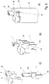
- Figure 6a and 5a, b show another spring terminal.
- This variant is shown in Figure 5a in an unconnected and in Figure 5b in a wired state with a conductor 10, wherein in Figures 5a and 5b part of the but in 6 shown housing 30 of the spring clamp has been hidden.
- This case 30 is somewhat different from the previous ones Figures 1 to 4 designed.
- the housing 3 is shown open on one side, so that the clamping spring 7 and other components can be mounted in the housing 3 from the open side.
- the clamping spring 7 is supported in plastic.
- a multi-part housing 30 is provided that has a lower housing part 31 and an upper housing part 32 that can be placed thereon.
- the lower housing part 31 is designed in the manner of a sleeve that is closed around the circumference here in cross-section and is rectangular here, which is open on one or two opposite end faces (up and down in the figures).
- a metallic assembly which has a (simple) clamping cage 13 (see in particular Figures 7a and c ), in which the clamping spring 7 can be inserted.
- the clamping cage 13 is at least U-shaped in a side view and has three legs 13a, 13b, 13c. It is open on the side, but this is not a problem since the lower housing part 31 centers the conductor 10 here.
- the clamping spring 7 is placed between these legs 13a, 13b, 13c. At least one of the legs 13a, b, c can be used to connect to an electrical assembly (not shown here), for example to connect to a plug (not shown here) or to a printed circuit board or the like. The same applies to the busbar 8 of FIG Figures 1 to 4 .
- the busbar 8 is in the Fig.1 in the side view, for example, L-shaped.
- This L is supplemented here by a further leg 13a, so that a support leg 13a is formed.
- the support leg 13a serves to support the (e.g. attached to it) support leg 7a of the clamping spring 7, the clamping leg 7b of which has a conductor 10 in the connected state Figure 5b for contacting presses against the leg 13c, which also has a current-conducting function or busbar function or takes over the function of the busbar.
- the clamping cage 13 with the clamping spring 7 can be inserted into the lower housing part 31 from an open side. In this way, these elements can be preassembled on one another so that they can be easily assembled further and are well protected in the lower housing part 31.
- the upper housing part 32 and the lower housing part 31 can be locked together at corresponding locking means 14 after the clamping cage 13 and the clamping spring 7 have been assembled together, as is the case Figure 7a shows well.
- the conductor insertion channel 5 and the actuation channel 6 for the handle 11 are formed in the housing upper part 32 . This in turn can be latched in the housing 30 such that an open position is formed in which the terminal point K is opened and a conductor 10 can be inserted into this terminal point K.
- the description of Figures 1 to 4 referred.
- a release element 12 is in turn provided on the one hand to release this locking position.
- this release element 12 is formed from a subassembly to the assembly of the elements 13 and 7.
- This sub-assembly can be made of all metal, all plastic, or a mixture of metal and plastic elements.
- This subassembly can also be preassembled on the clamping cage 13 and can be inserted into the housing 30 together with this and the conductor rail 7 .
- two short metallic legs 13d, 13e are bent upwards out of the leg 13b of the clamping cage against the conductor insertion direction x, which form the bearing block 15 for the triggering element 12 in the manner of a rocker, which can be made of plastic or metal and on the bearing block 15 corresponding shots is pivoted.
- the bearing block 15 can also be designed as an element made of metal or plastic that is separate from the clamping cage 13 and can be fastened to the clamping cage 13 ( Figures 7a-c ) and in turn has receptacles for the triggering element 12 . This is the difference 7 to the figure 5 and 6 .
- the release element 12 in turn has two lever arms 12a, 12b.
- a force can therefore be exerted on the triggering element 12 with the conductor end of the conductor 10 in the conductor insertion direction X in order to release the pusher 11 from the open position and thus from the latched position.
- the conductor 10 presses on one of the two Lever arms, namely the lever arm 12a.
- the triggering element 12 rotates about its axis of rotation 12c and the other lever arm 12b acts as a triggering contour on one or two corresponding actuating contour(s) 11f of the pusher 11 .
- These are designed here as arms that extend to the side of the clamping cage. In this way, reliable triggering on two arms of the handle 11 can be implemented.
- the clamping leg 7b then presses the conductor end of the conductor 10 against the leg 13a.
- the pusher 11 can be released directly from the locked position, as described above.
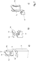
- this spring-loaded terminal also has a multi-part housing 40, with a lower housing part 41 and an upper housing part 32 that can be placed thereon.
- the upper housing part 32 corresponds to that based on FIG Figures 5a to 7c described housing upper part 32.
- the lower housing part 41 is longer than the lower housing part 31 described above and has at its lower end a receptacle 42 for receiving an electrical contact, for example a so-called blade contact, as is provided in particular on printed circuit boards.
- a terminal 16 is accommodated in the cavity of the extended housing base 41 .
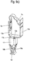
- Connection 16 is included, as in 9c shown, connected to the clamping cage 13 and thus serves, as described above, as a connection to an electrical assembly (not shown here).
- connection 16 has an intermediate piece 17 which is connected to the leg 13b of the clamping cage 13 via a leg 17a.
- two clamping legs 18a, 18b extend, which are bent away from the side edges of the intermediate piece 17 in an approximately V-shape running towards one another until they touch one another, the free ends forming a receptacle 19 from one another are bent running away, so that, for example, a knife contact can be inserted through the receptacle 42 of the lower housing part 41 and the receptacle 19 between the clamping legs 18a, 18b, and electrical contact is thus provided between the knife contact (not shown) and the clamping cage 13.
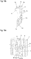
- the 10a to 13 show another possible—and advantageous—embodiment of a spring clamp designed according to the invention. They show another spring-loaded terminal 1, the structure and function of which the spring-loaded terminal 1 of Fig.1a - c and Fig. 2a-b and 3 largely corresponds. In this respect, the description of these figures also applies in full to these figures.
- the variant already mentioned above is realized in that the free end 11a of the pusher 11 does not protrude beyond the outside of the housing 3 to the outside. Rather, it lies within the actuating channel 6.
- At least one actuating contour in particular a recess 11b—can advantageously be formed on this free end 11a for attaching a tool, in particular a screwdriver, to the pusher 11 .
- This indentation 11b or one of the indentations is preferably in turn dimensioned in such a way that a screwdriver can be inserted into the indentation 11b ( Figure 4a , Figure 4c ).
- This recess 11b is formed here by a lateral projection on the pusher 11.
- the term indentation refers to the end 11a and a view of this end in the direction of insertion X.
- the latch 11 has a lateral latching edge 11h, which can be latched in the latching state R behind the latching edge 3a by moving perpendicularly to the insertion direction X and can be released from the latched state R by moving in the opposite direction transversely or perpendicularly to the insertion direction X.
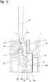
- the spring force of the clamping spring 7 moves the pusher 11 transversely to the direction of insertion into the latching position, and that the pusher 11 is moved in the opposite direction out of the Locking state R can be released (see Fig.13 ).
- the pusher 11 in turn has at least one depression 11b for attaching an actuating tool, which is dimensioned such that the actuating tool - here the screwdriver - can be used to move the pusher in the insertion direction X and also pivoting vertically to the insertion direction X can be realized.
- This depression 11b is here advantageously (but not necessarily) formed laterally on the pusher 11 at the end 11a.
- the end of the screwdriver S can then engage in this recess 11b and rest against an edge K at the end of the actuation opening 6 on the housing 3, so that defined pivoting is possible ( Fig.13 , there to the left so that the screwdriver turns around the edge K as the axis of rotation).
- the pusher 11 is thus released from the latch and the latched state is released overall, en 11 and 13 demonstrate.
- a further, preferably central depression 11b′ can be provided, which also enables the push-button 11 to be pressed parallel to or in the direction of insertion 11 . Then the pusher 11 can have two of the indentations 11b, 11b'. This is advantageous, structurally simple and facilitates handling. Otherwise, the function and handling of this embodiment correspond to that of Fig. 1a, b and 2a , b .
- the push button 11 thus has two indentations 11b, 11b' for attaching the actuating tool, which is/are dimensioned such that, overall, these two indentations 11b, 11b' can be used with the operating tool to move the push button in the insertion direction X and also perpendicular to the insertion direction X is realizable.
- one or here two stop means is/are provided on the rocker-like triggering element 12 .
- the rocker or the rocker arm is designed as the triggering element in such a way that one or both of its lever arms 12a, 12b can strike an abutment, e.g. a section of the conductor rail 8 or an edge of the housing or the like, when rotated.
- one or two geometric end stops 12d, 12e can easily be realized, which as the stop means or means realize one or both of the following functions: protection against excessive rotation of the triggering element 12 or here the rocker arm when tensioning or producing the locking state and against excessive twisting of the triggering element 12 when triggered by means of the conductor 10.
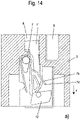
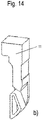
- the 14a ) and b) show another possible—and advantageous—embodiment of a spring-loaded terminal designed according to the invention. They show another spring-loaded terminal 1, the structure and function of which the spring-loaded terminal 1 of Fig.1a - c and Fig. 2a-b and 3 largely corresponds. In this respect, the description of these figures also applies in full to these figures.
- the pusher 11 can in turn be put into the latching state by pressing into the actuating channel 6, pressing on the clamping leg 7b in the direction of conductor insertion X and latching on the housing 3, in which the clamping leg is pivoted in such a way that a conductor can be inserted into the intended location.
- the pusher 11 is positioned in such a way that the locking state can be established with it, but cannot be released again by tilting it with a screwdriver.
- the pusher as an adjusting means is thus eliminated.
- the locking state is generated by pressure on the clamping leg 7b in the conductor insertion direction. Furthermore, the locking state R is not generated by locking an element on the free clamping edge 7d of the clamping leg and can be released by inserting the conductor into the housing 3 in the conductor insertion direction X.
Description
Die vorliegende Erfindung betrifft eine Federkraftklemme nach dem Oberbegriff des Anspruchs 1.The present invention relates to a spring clamp according to the preamble of
Derartige Federkraftklemmen sind aus der
Federkraftklemmen in einer Ausgestaltung als Direktsteckklemmen (Push-In) mit einer als Druckfeder ausgebildeten Klemmfeder, welche den Leiter gegen die Stromschiene presst, sind in vielfältigen Ausführungsformen bekannt. Sie unterscheiden sich vor allem aufgrund ihrer Anwendung beispielsweise in Abhängigkeit von der benötigten Stromtragfähigkeit der Stromschiene, der Federkraft der Klemmfeder und/oder ihren Einbauverhältnissen, insbesondere ihrer Baugröße. Dabei sind eine einfache Montage und eine kostengünstige Herstellung dauerhaft gestellte Anforderungen an eine solche Klemme.Spring-loaded terminals designed as direct plug-in terminals (push-in) with a clamping spring designed as a compression spring, which presses the conductor against the busbar, are known in many different embodiments. They differ mainly due to their application, for example depending on the required current carrying capacity of the busbar, the spring force of the clamping spring and/or their installation conditions, in particular their size. In this case, simple assembly and cost-effective production are permanent requirements for such a clamp.
Die
Aus der
Es ist ausgehend pn der
Die Aufgabe wird gelöst mit einer Federkraftklemme nach Anspruch 1. Vorteilhafte Ausführungsformen sind den Unteransprüchen zu entnehmen.The object is achieved with a spring-loaded terminal according to
Das Lösen der Geöffnetstellung bzw. der Verraststellung des Klemmschenkels ist derart auf zwei verschiedene Weisen möglich. Dies ist vorteilhaft, da dann, wenn das Betätigen des einen Verstellmittels im Einzelfall nicht zum Lösen der Raststellung der Klemmfeder bzw. des Klemmschenkels führt, hierzu noch das andere Verstellmittel genutzt werden kann, um die Klemmfeder bzw. deren Klemmschenkel aus der Raststellung zu lösen.The release of the open position or the locking position of the clamping leg is possible in two different ways. This is advantageous because if the actuation of one adjustment means does not result in the locking position of the clamping spring or the clamping leg being released in an individual case, the other adjustment means can still be used to release the clamping spring or its clamping leg from the locking position.
Aus der
Dabei ist der Rastzustand nicht durch Verrasten eines Elementes an einer freien Klemmkante des Klemmschenkels erzeugt und der Rastzustand ist durch Einbringen des Leiters in Leitereinführrichtung in das Gehäuse lösbar.The latched state is not created by latching an element on a free clamping edge of the clamping leg, and the latched state can be released by inserting the conductor into the housing in the conductor insertion direction.
Es ist nach dieser als eigene Erfindung zu betrachtenden Lösung sowie aber auch als Weiterbildung des Anspruchs 1 geeigneten Lösung vorteilhaft, dass der Rastzustand nicht durch Verrasten eines Elementes an einer freien Klemmkante des Klemmschenkels erzeugt ist und dass dennoch in einfacher Weise der Rastzustand durch Einbringen des Leiters in Leitereinführrichtung in das Gehäuse lösbar ist. Denn an der Klemmkante des Klemmschenkels sind bzw. wären relativ hohe Kräfte zum Lösen der Verraststellung erforderlich. Zudem kann an der Klemmkante durch das Verrasten Verschleiß auftreten. Dieses Problem wird derart vermieden. Es sind zudem außerhalb der Klemmkante, bei einem Verrasten durch Druck auf den Klemmschenkel und Verrasten eines Drückers am Gehäuse, definiertere Reibverhältnisse gegeben. Es ist entsprechend auch bevorzugt, dass der Rastzustand durch Druck auf den Klemmschenkel in Leitereinführrichtung erzeugt ist, beispielsweise mit Hilfe eines auf den Klemmschenkel wirkenden Betätigungselement, insbesondere Drückers, der am Gehäuse in einer Verraststellung verrastbar ist, in welcher er durch Druck auf den Klemmschenkel in Leitereinführrichtung diesen in den Offenstellung verrastet hält. Derart sind nur relativ geringe Kräfte und darüber hinaus relativ genau definierte Kräfte zum Lösen des Klemmschenkels mit dem Leiter aus der Verraststellung erforderlich. Diesen vorteilhaften Effekt macht sich die Erfindung auch zum Lösen der Verraststellung mit dem Leiter selbst zu Nutze, indem der Drücker mit einem beweglichen Auslöseelement gekoppelt ist, dass mit dem Klemmschenkel zusammenwirkt und das durch Druck des Leiters bewegbar ist, um derart auch den Drücker aus seiner Verraststellung zu lösen.According to this solution, which is to be regarded as a separate invention and also as a suitable development of
Das erste der beiden Verstellmittel aufweist ein bewegliches Auslöseelement, auf welches das Ende des zu kontaktierenden Leiters beim Lösen des Leiters einwirkt und mit dem der Klemmschenkel der Klemmfeder direkt oder indirekt - im letzteren Fall über wenigstens ein zwischengeschaltetes Element - aus dem Rastzustand lösbar ist. Im ersten Fall - direktes Einwirken - ist es beispielsweise auch denkbar, dass das Auslöseelement einstückig mit dem Drücker ausgebildet ist.The first of the two adjusting means has a movable release element, which is acted upon by the end of the conductor to be contacted when the conductor is released and with which the clamping leg of the clamping spring can be released from the latched state directly or indirectly - in the latter case via at least one element connected in between. In the first case—direct action—it is also conceivable, for example, for the triggering element to be designed in one piece with the pusher.
Das zweite der beiden Verstellmittel umfasst ein Betätigungselement zum Bewegen des Klemmschenkels. Dann ist es zweckmäßig, dass das Betätigungselement selbst gemeinsam mit dem Klemmschenkel der Klemmfeder in dem Rastzustand verrastbar ist und selbst direkt aus dem Rastzustand lösbar ist, wodurch auch der Klemmschenkel der Klemmfeder mit aus dem Rastzustand lösbar ist.The second of the two adjusting means includes an actuating element for moving the clamping leg. Then it is expedient that the actuating element itself can be latched together with the clamping leg of the clamping spring in the latched state and itself can be released directly from the latched state, whereby the clamping leg of the clamping spring can also be released from the latched state.
Das Lösen der Geöffnetstellung bzw. der Verraststellung des Klemmschenkels ist derart auf zwei verschiedene Weisen möglich. So kann das Lösen der Verraststellung des Klemmschenkels einerseits mit Hilfe des Leiters erfolgen und andererseits mit Hilfe des Betätigungselements. Dies ist vorteilhaft, da derart auch dann, wenn der Leiter beispielsweise als ein sehr dünner Mehrlitzenleiter ausgebildet ist, mit dem nur eine sehr geringe Kraft auf das Auslöseelement ausgeübt werden kann, der Drücker selbst direkt dazu benutzt werden kann, um die Klemmfeder bzw. deren Klemmschenkel aus der Raststellung zu lösen.The release of the open position or the locking position of the clamping leg is possible in two different ways. So the release of the locked position of the clamping leg can be done on the one hand with the help of the conductor and on the other hand with the help of the actuating element. This is advantageous because such even if the conductor is formed, for example, as a very thin multi-strand conductor, with only one very little force can be exerted on the trigger element, the pusher itself can be used directly to release the clamping spring or its clamping legs from the locked position.
Nach einer konstruktiv gut umsetzbaren und sicher arbeitenden Variante ist vorgesehen, dass das Betätigungselement ein Drücker zum Bewegen des Klemmschenkels ist, der in einem Betätigungskanal des Gehäuses in Einsteckrichtung verschieblich ist und begrenzt senkrecht zur Einsteckrichtung beweglich ist und der im Gehäuse an einer Rastkante in dem Rastzustand verrastbar ist.According to a variant that is easy to implement in terms of design and that works reliably, it is provided that the actuating element is a pusher for moving the clamping leg, which is displaceable in an actuating channel of the housing in the direction of insertion and is movable to a limited extent perpendicular to the direction of insertion and which in the housing at a latching edge in the latched state can be locked.
Gut realisierbar ist dies beispielweise dadurch, dass der Drücker eine seitliche Rastkante aufweist, die durch Bewegen senkrecht zur Einsteckrichtung hinter der Rastkante des Gehäuses in dem Rastzustand verrastbar und durch entgegengesetztes Bewegen aus dem Rastzustand lösbar ist.This can easily be achieved, for example, by the push button having a lateral latching edge which can be latched into the latched state by moving perpendicularly to the insertion direction behind the latching edge of the housing and can be released from the latched state by moving in the opposite direction.
Nach einer vorteilhaften und einfach handhabbaren Variante kann vorgesehen sein, dass der Drücker bei dem manuellen Bewegen in Einsteckrichtung nach dem Vorbeigleiten an der Rastkante durch die Federkraft der Klemmfeder in die Raststellung bewegt wird und dass der Drücker durch Bewegen mit einem manuell betätigbaren Betätigungswerkzeug wie einem Schraubendreher in entgegengesetzter Richtung aus dem Rastzustand lösbar ist.According to an advantageous and easy-to-handle variant, it can be provided that the push-button is moved into the locking position by the spring force of the clamping spring during manual movement in the insertion direction after sliding past the locking edge, and that the push-button is moved by moving it with a manually operable operating tool such as a screwdriver can be released from the locked state in the opposite direction.
Es ist weiter zweckmäßig, da derart der Drücker in Einsteckrichtung relativ kurz gehalten werden kann, wenn der Drücker eine Vertiefung zum Ansetzen eines Betätigungswerkzeuges aufweist, die so bemessen ist, dass mit dem Betätigungswerkzeug ein Bewegen des Drückers in Einsteckrichtung und auch senkrecht zur Einsteckrichtung realisierbar ist.It is also useful because the push button can be kept relatively short in the direction of insertion if the push button has a recess for attaching an operating tool, which is dimensioned such that the operating tool can be used to move the push button in the direction of insertion and also perpendicular to the direction of insertion .
Nach einer konstruktiv zudem kompakt und kostengünstig umsetzbaren Variante ist vorgesehen, dass das Auslöseelement als ein in dem Gehäuse schwenkbar gelagerter Kipphebel ausgebildet ist. Dabei ist zweckmäßig, wenn der Kipphebel zwei Hebelarme aufweist, von denen der eine Hebelarm dazu ausgelegt ist, mit dem Leiter verschwenkt zu werden und von denen der andere Hebelarm dazu ausgelegt ist, auf den Drücker einzuwirken, um diesen aus dem Rastzustand zu lösen.According to a variant that is also structurally compact and can be implemented cost-effectively, it is provided that the triggering element is designed as a rocker arm that is pivotably mounted in the housing. It is expedient if the rocker arm has two lever arms, one of which is designed to be pivoted with the conductor and the other lever arm of which is designed to act on the pusher to release it from the locked state.
Die Federkraftklemme eignet sich nicht nur für Vollleiter, sondern in besonderem Maße auch für Litzenleiter. Denn der Litzenleiter ist ohne ein Aufspleißen der Litzen im Rastzustand im Freiraum der Kammer im Gehäuse hin und her verschieblich. Es ist ein Material für die Stromschiene wählbar, das gute elektrische Leitfähigkeit aufweist, beispielsweise Kupfer oder eine Kupferlegierung. Für die Klemmfeder ist ein Federstahl als Herstellmaterial vorteilhaft.The spring-cage terminal is not only suitable for solid conductors, but also particularly for stranded conductors. This is because the stranded conductor can be moved back and forth in the free space of the chamber in the housing without the strands fanning out in the latched state. A material can be selected for the conductor rail that has good electrical conductivity, for example copper or a copper alloy. Spring steel is advantageous as the manufacturing material for the clamping spring.
Im Folgenden wird die Erfindung anhand eines Ausführungsbeispiels unter Bezug auf die Zeichnungen näher beschrieben. Es zeigen:
- Fig. 1a
- eine Seitenansicht auf eine Federkraftklemme mit einem Klemmschenkel, der zum Verklemmen eines in die Federkraftklemme einführbaren bzw. eingeführten elektrischen Leiters vorgesehen ist, in einem nicht verrasteten Zustand;
- Fig. 1b
- die Federkraftklemme aus
Fig. 1a ) mit dem Klemmschenkel in einem Rastzustand; - Fig. 2a
- eine Seitenansicht der Federkraftklemme aus
Fig. 1b ) mit einem Leiter während eines Einführens des Leiters in die Federkraftklemme, wobei sich der Klemmschenkel noch in dem Rastzustand befindet; - Fig. 2b
- die Federkraftklemme aus
Fig. 2a ) mit einem in die Federkraftklemme eingeführten elektrischen Leiter, wobei der Klemmschenkel aus dem Rastzustand entrastet ist; - Fig. 3a
- eine Seitenansicht eines Betätigungselementes der Federkraftklemme aus
Fig.1a undFig. 2a ); - Fig. 3b
- eine Draufsicht auf das Betätigungselement aus
Fig. 3a ; - Fig. 4a
- eine geschnittene Darstellung einer Federkraftklemme ähnlich zu
Fig. 1a und2a mit einem Leiter während eines Einführens des Leiters in die Federkraftklemme, wobei sich der Klemmschenkel noch in dem Rastzustand befindet; - Fig. 4b
- eine Ausschnittsvergrößerung aus
Fig. 4a ; - Fig. 4c
- die Federkraftklemme aus
Fig. 4a ) in perspektivischer und geschnittener Ansicht, hier mit einem in die Federkraftklemme eingeführten elektrischen Leiter mit dem Klemmschenkel in dem Rastzustand; - Fig. 5a, b
- eine weitere Federkraftklemme einmal in einem unbeschalteten und einmal in einem beschalteten Zustand, wobei ein Teil des Gehäuses der Federkraftklemme ausgeblendet worden ist;
- Fig. 6a
- eine perspektivische Ansicht der Federkraftklemme aus
Fig. 5 ; - Fig. 6b-c
- perspektivische Ansichten von Bauelementen und/oder Baugruppen der Federkraftklemme aus
Fig. 6a ; und - Fig. 7a-c
- perspektivische Ansichten von Varianten einzelner Bauelemente und/oder Baugruppen für die Federkraftklamme aus
Fig. 6a . - Fig. 8a, b
- eine weitere Federkraftklemme einmal in einem unbeschalteten und einmal in einem beschalteten Zustand, wobei ein Teil des Gehäuses der Federkraftklemme ausgeblendet worden ist;
- Fig. 8c
- eine perspektivische Ansicht der Federkraftklemme aus den
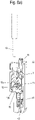
Fig. 8a ,b; - Fig. 9a-c
- perspektivische Ansichten von Bauelementen und/oder Baugruppen der Federkraftklemme aus
Fig. 8c ; - Fig. 10a
- eine perspektivische Schnittansicht einer weiteren Federkraftklemme mit einem Klemmschenkel, der zum Verklemmen eines in die Federkraftklemme einführbaren bzw. eingeführten elektrischen Leiters vorgesehen ist, in einem nicht verrasteten, nicht geöffneten Zustand einer Klemmfeder;
- Fig. 10b
- eine perspektivische Ansicht eines als Drücker ausgebildeten Betätigungselementes der Federkraftklemme aus
Fig. 10a ); - Fig. 11
- eine Seiten-Schnittansicht der Federkraftklemme aus
Fig. 10a ) mit einem daran angesetzten Betätigungswerkzeug in einem Zustand, in dem sich der Klemmschenkel einer Klemmfeder in einen verrasteten Zustand versetzt wird und in dem dann ein Leiter in eine Klemmstelle einführbar ist; - Fig. 12
- die Federkraftklemme aus
Fig. 10a ) im Rastzustand mit einem in die Klemmstelle eingeführten Leiter und mit einem Betätigungswerkzeug; - Fig. 13
- die Federkraftklemme aus
Fig. 10a ) im Rastzustand ausFig. 12 ) ohne einen in die Klemmstelle eingeführten Leiter und mit einem relativ zuFig. 11 an anderer Stelle des Drückers angesetzten Betätigungswerkzeug, mit dem der Rastzustand gelöst werden soll; und - Fig. 14
- eine Seiten-Schnittansicht einer weiteren Federkraftklemme in einem geöffneten Rastzustand und in b) als Drücker ausgebildeten Betätigungselementes der Federkraftklemme aus
Fig. 10a .
- Fig. 1a
- a side view of a spring-loaded terminal with a clamping leg, which is provided for clamping an insertable or inserted electrical conductor into the spring-loaded terminal, in a non-latched state;
- Fig. 1b
- the spring clamp
Fig. 1a ) with the clamping leg in a detent state; - Figure 2a
- a side view of the spring clamp
Fig. 1b ) with a conductor during insertion of the conductor into the spring clamp with the clamp leg still in the latched state; - Figure 2b
- the spring clamp
Figure 2a ) with an electrical conductor inserted into the spring-loaded terminal, the terminal leg being disengaged from the latched state; - Figure 3a
- a side view of an actuating element of the spring terminal
Fig.1a andFigure 2a ); - Figure 3b
- a top view of the actuating element
Figure 3a ; - Figure 4a
- a sectional view of a spring clamp similar to
Fig. 1a and2a with a conductor during insertion of the conductor into the spring force clamp, with the clamp leg still being in the latching state; - Figure 4b
- an enlargement of a section
Figure 4a ; - Figure 4c
- the spring clamp
Figure 4a ) in a perspective and sectional view, here with an electrical conductor inserted into the spring-loaded terminal with the terminal leg in the latched state; - Fig. 5a, b
- a further spring-loaded terminal once in an unconnected state and once in a connected state, part of the housing of the spring-loaded terminal having been hidden;
- Figure 6a
- a perspective view of the spring clamp
figure 5 ; - Fig. 6b-c
- perspective views of components and / or assemblies of the spring clamp
Figure 6a ; and - Fig. 7a-c
- perspective views of variants of individual components and / or assemblies for the spring clamp
Figure 6a . - 8a, b
- a further spring-loaded terminal once in an unconnected state and once in a connected state, part of the housing of the spring-loaded terminal having been hidden;
- Figure 8c
- a perspective view of the spring clamp from the
Figure 8a ,b; - Fig. 9a-c
- perspective views of components and / or assemblies of the spring clamp
Figure 8c ; - Figure 10a
- a perspective sectional view of a further spring-loaded terminal with a clamping leg, which is provided for clamping an insertable or inserted into the spring-loaded electrical conductor, in a non-latched, non-open state of a clamping spring;
- Figure 10b
- a perspective view of an actuating element designed as a pusher of the spring-loaded terminal
Figure 10a ); - 11
- Figure 12 shows a side sectional view of the spring clamp
Figure 10a ) with an actuating tool attached thereto in a state in which the clamping leg of a clamping spring is moved into a latched state and in which a conductor can then be inserted into a clamping point; - 12
- the spring clamp
Figure 10a ) in the locked state with a conductor inserted into the terminal point and with an actuating tool; - 13
- the spring clamp
Figure 10a ) in resting state12 ) without a conductor inserted into the terminal point and with a relative to11 operating tool set elsewhere on the pusher, with which the latched state is to be released; and - 14
- a side sectional view of a further spring-loaded terminal in an open locking state and in b) designed as a pusher actuating element of the spring-loaded terminal
Figure 10a .
Die
Die Federkraftklemme 1 weist ein Gehäuse 3 auf, in dem ein Direktsteckanschluss 2 ausgebildet ist. Das Gehäuse 3 besteht vorzugsweise aus einem isolierenden Kunststoff. In dem Gehäuse 3 ist eine zu wenigstens einer Seite hin offene Kammer 4 ausgebildet. Die Kammer 4 weist hier eine Rückwand auf. Die Kammer 4 ist zudem einerseits durch einen Leitereinsteckkanal 5 mit einer der Außenseiten des Gehäuses - "Einsteckseite" genannt, hier die Oberseite - verbunden und andererseits durch einen Betätigungskanal 6. Der Betätigungskanal 6 verläuft im Wesentlichen parallel zum Leitereinsteckkanal 5. Der Betätigungskanal 6 ist hier in sich gestuft ausgebildet (siehe
In der Kammer 4 sind zum Ausbilden des Direktsteckanschlusses 2 zumindest eine Klemmfeder 7 und eine Stromschiene 8 angeordnet. Optional kann ein Klemmkäfig aus Metall vorgesehen sein, der zum Abstützen der Klemmfeder 7 und der Stromschiene 8 dient. Hier ist kein Klemmkäfig vorgesehen. Diese Funktion übernehmen hier Wandungen der Kammer 4 des Gehäuses3.At least one
Die Klemmfeder 7 ist U-förmig oder V-förmig ausgebildet und weist einen Stützschenkel 7a und einen Klemmschenkel 7b auf. Der Stützschenkel 7a stützt sich an einem Widerlager ab. Dieses Widerlager wird hier von einem Vorsprung 3b an einer Wand der Kammer 4 gebildet. Der Klemmschenkel 7b ist über einen bogenförmigen Rücken 7c mit dem Stützschenkel 7a verbunden. Der Rücken 7c übergreift eine Stützkontur 9 des Gehäuses 3, die in die Kammer 4 vorsteht. Diese Stützkontur 9 ist hier beispielhaft zylindrisch und in
Der verschwenkbare Klemmschenkel 7b dient dazu, mit Federkraft 10 im Bereich einer Klemmstelle K auf einen Leiter 10 einzuwirken und diesen Leiter 10 gegen die Stromschiene 8 zu drücken. Derart wird ein elektrisch leitender Kontakt zwischen dem eingeführten Leiter 10 und der Stromschiene 8 hergestellt. Dies erschließt sich gut aus
Der Leiter 10 kann in einer Leitereinsteckrichtung X durch den Leitereinsteckkanal 5 in die Kammer 4 in den Bereich der Klemmstelle K geführt werden (siehe
In dem Betätigungskanal 6 ist ein Betätigungselement angeordnet. Das Betätigungselement ist hier in bevorzugter Ausgestaltung als ein Drückelement - kurz "Drücker 11" genannt, ausgebildet, der im Betätigungskanal 6 verschieblich geführt ist. Vorzugsweise steht ein freies Ende 11a des Drückers 11 über die Außenseite des Gehäuses 3 nach außen vor, damit es gut zugänglich ist. Dies ist vorteilhaft aber nicht zwingend. Weiter kann vorteilhaft an diesem freien Ende 11a eine Betätigungskontur - insbesondere eine Vertiefung 11b - zum Ansetzen eines Werkzeugs, insbesondere eines Schraubendrehers an dem Drücker 11 ausgebildet sein. Diese Vertiefung 11b ist vorzugsweise derart bemessen, dass ein Schraubendreher relativ fest und weit in die Vertiefung 11b einführbar ist (
Das andere Ende 11c des Drückers 11 ragt bis in die Kammer 4. Der Drücker 11 weist ferner eine Drückkontur 11d - hier zwischen seinen beiden Enden 11a und 11c - auf. Diese Drückkontur 11d dient dazu, auf den Klemmschenkel 7b in Einsteckrichtung mit dem Drücker 11 eine Kraft ausüben zu können, um den Klemmschenkel 7b zu öffnen.The
Unterhalb der ersten Drückkontur 11d weist der Drücker 11 einen Schlitz 11e nach Art einer Durchgangsöffnung mit seitlichen Wandungen auf. Der Klemmschenkel 7b durchsetzt diesen Schlitz 11e. Der Klemmschenkel 7b ist im Schlitz 11e begrenzt schwenkbar.Below the first
Der Drücker 11 weist ferner eine Betätigungskontur 11f auf. Hier ist diese Betätigungskontur 11f unterhalb des Schlitzes 11e am Ende 11c vorgesehen.The
Unterhalb des Endes 11c des Drückers 11 - hier unterhalb der Betätigungskontur 11f - ist ein bewegliches Auslöseelement 12 in der Kammer 4 angeordnet. Dieses Auslöseelement 12 ist hier in vorteilhafter - aber nicht zwingender - Ausgestaltung als ein Kipphebel ausgebildet, der zwei um eine Drehachse drehbare Hebelarme 12a, 12b aufweist.A
Der Drücker 11 weist ferner wenigstens eine seitliche Vertiefung 11g aus, an welcher eine erste Hinterschneidung 11h (siehe auch
Durch Eindrücken des Drückers 11 in der Betätigungsöffnung 6 in die Einsteckrichtung X kann Druck auf den Klemmschenkel 7b ausgeübt werden.By pressing the
Dies dient einerseits dazu, bei eingeführtem Leiter die Klemmstelle K zu öffnen, um den Leiter 10 entnehmen zu können.On the one hand, this serves to open the terminal point K when the conductor is inserted, in order to be able to remove the
Ausgehend von der Stellung der
Derart ist die Klemmfeder 7 bzw. deren Klemmschenkel 7b in einer Geöffnet-Stellung im Gehäuse 3 verrastbar bzw. verrastet (siehe
In dieser Stellung kann auf einfache Weise der Leiter 10 bis in den Bereich der Klemmstelle K geschoben werden.In this position, the
Das Lösen der Geöffnetstellung bzw. der Verraststellung des Klemmschenkels 7b ist auf zwei verschiedene Arten möglich.The release of the open position or the locked position of the clamping
Da der Rastzustand nicht durch Verrasten eines Elementes an der freien Klemmkante 7d, also den dem Ende des Rastschenkels 7b erfolgt, an dem der Leiter zu Klemmen ist, ist zum Lösen des Klemmschenkels aus der Verraststellung nur eine sehr geringe Kraft erforderlich. Dies macht sich die Erfindung zu Nutze, indem sie die Verraststellung bzw. den Rastzustand nicht an der Klemmkante des Klemmschenkels herstellt sondern durch Druck auf den Klemmschenkel in Leitereinführrichtung. Dabei bzw. derart kann auch dann, wenn der Leiter 10 beispielsweise als sehr dünner Mehrlitzenleiter ausgebildet ist, mit dem nur eine sehr geringe Kraft auf das Auslöseelement 12 ausgeübt werden kann, der Drücker 11 selbst direkt dazu benutzt werden, um die Klemmfeder 7 bzw. deren Klemmschenkel 7b aus der Raststellung zu lösen.Since the locking state is not achieved by locking an element on the
Konstruktiv ist dies auf verschiedene Weise umsetzbar, so zweckmäßigerweise auf die nachfolgend beschriebene Art. Danach wird der Drücker 11 zum Lösen der Verraststellung etwas im Gehäuse 3 so bewegt - hier seitlich senkrecht zur Einsteckrichtung X - verschoben oder verschwenkt, dass die Hinterschneidung 11h aus der Verraststellung an der Rastkante 3a herausbewegt wird und die Verrastung des Drückers 11 am Gehäuse 3 gelöst wird. Damit wird auch die Raststellung des Rastschenkels 7b gelöst. Derart kann sich der Klemmschenkel 7b der Klemmfeder 7 entspannen und den Leiter 10 in der Klemmstelle K gegen die Stromschiene 8 drücken. Dies ist hier manuell oder mit einem Werkzeug denkbar.Structurally, this can be implemented in various ways, expediently in the manner described below. Then, to release the latched position, the
Alternativ kann mit dem Leiterende des Leiters 10 in Leitereinführrichtung X eine Kraft auf das Auslöseelement 12 ausgeübt werden, um den Drücker 11 aus der Offenstellung und damit aus der Verraststellung zu lösen. Der Leiter 10 drückt dabei auf den einen der beiden Hebelarme, nämlich den Hebelarm 12a. Hierdurch dreht sich das Auslöseelement um seine Drehachse 12c und der andere Hebelarm 12b wirkt auf die Betätigungskontur 11f des Drückers 11 ein. Dieses Einwirken bewegt wiederum den Drücker 11, der am Gehäuse 3 abgestützt ist, so, dass er sich aus der Verrastung an der Rastkante 6a löst, wodurch der Drücker 11 freigegeben wird und im Betätigungskanal 6 wieder entgegen der Steckrichtung X durch die Kraft des freigegebenen Klemmschenkels 7b etwas nach oben gleitet.Alternatively, a force can be exerted on the triggering
Dieses Lösen der Verraststellung ist der übliche Weg zum Beschalten der Federkraftklemme 1. Das zuvor beschriebene Bewegen des Drückers 11 ist eine Alternativlösung, falls z.B. der Leiter 10 so flexibel ist, dass mit ihm in einem Einzelfall keine genügende Kraft zum Betätigen des Auslöseelementes 12 erzeugt werden kann.This release of the locking position is the usual way to connect the spring-loaded
Es ist vorteilhaft, wenn die Vertiefung 11b an dem aus dem Gehäuse 4 vorstehenden Ende 11a des Drückers 11 so tief bemessen ist, dass mit dem eingesteckten Schraubendreher oder einem sonstigen Werkzeug eine Kraft auf den Drücker 11 ausgeübt werden kann, um diesen aus seiner Verraststellung zu lösen. Dies erschließt sich gut aus dem Zusammenspiel der
Der Drücker 11 weist hier noch eine Stufung 11i auf, die mit einer Stufung 6a des Betätigungskanals korrespondiert und eine Einschubbegrenzung für den Drücker 11 in Leitereinsteckrichtung X realisiert (
Die
Dieses Gehäuse 30 ist etwas anders als in den vorhergehenden
Nach
Das Gehäuseunterteil 31 ist nach Art einer hier im Querschnitt umfangsgeschlossen sowie hier rechteckigen Hülse gestaltet, die an einer oder zwei gegenüberliegenden Stirnseiten (in den Fig. nach oben und unten) offen steht.The
Nach
Zwischen diese Schenkel 13a, 13b, 13c ist die Klemmfeder 7 gesetzt. Wenigstens einer der Schenkel 13a, b, c kann zum Anschluss an eine (hier nicht dargestellte) elektrische Baugruppe genutzt werden, beispielsweise zum Anschluss an einen hier nicht dargestellten Stecker oder an eine Leiterplatte oder dgl.. Analoges gilt für die Stromschiene 8 der
Dagegen ist die Stromschiene 8 in der
Der Klemmkäfig 13 ist mit der Klemmfeder 7 ist von einer offenen Seite her in das Gehäuseunterteil 31 einsetzbar. Derart sind diese Elemente aneinander vormontierbar, damit leicht weiter montierbar und liegen gut geschützt im Gehäuseunterteil 31.The clamping
Vorzugsweise sind das Gehäuseoberteil 32 und das Gehäuseunterteil 31 an korrespondierenden Rastmitteln 14 miteinander verrastbar, nachdem der Klemmkäfig 13 und die Klemmfeder 7 zusammen montiert worden sind, wie dies die
In dem Gehäuseoberteil 32 sind der Leitereinsteckkanal 5 und der Betätigungskanal 6 für den Drücker 11 ausgebildet. Dieser ist wiederum in Gehäuse 30 so verrastbar, dass eine Offenstellung gebildet wird, in welcher die Klemmstelle K geöffnet und ein Leiter 10 in diese Klemmstelle K einführbar ist. Insoweit wird auf die Beschreibung der
Zum Lösen dieser Raststellung ist wiederum einerseits ein Auslöseelement 12 vorgesehen. Nach
Nach
Der Lagerbock 15 kann auch als ein zum Klemmkäfig 13 separates Element aus Metall oder Kunststoff ausgebildet sein, dass an dem Klemmkäfig 13 befestigbar ist (
Das Auslöseelement 12 weist wiederum zwei Hebelarme 12a, 12b auf. Daher kann mit dem Leiterende des Leiters 10 in Leitereinführrichtung X eine Kraft auf das Auslöseelement 12 ausgeübt werden, um den Drücker 11 aus der Offenstellung und damit aus der Verraststellung zu lösen. Der Leiter 10 drückt dabei auf den einen der beiden Hebelarme, nämlich den Hebelarm 12a. Hierdurch dreht sich das Auslöseelement 12 um seine Drehachse 12c und der andere Hebelarm 12b wirkt als Auslösekontur auf eine oder zwei korrespondierende Betätigungskontur(en) 11f des Drückers 11 ein. Diese sind hier als Arme ausgestaltet, die sich seitlich des Klemmkäfigs erstrecken. Derart ist ein sicheres Auslösen an zwei Armen des Drückers 11 realisierbar. Dieses Einwirken bewegt wiederum den Drücker 11, der am Gehäuse 3 rastend abgestützt ist, so, dass er sich aus der Verrastung an der Rastkante 6a löst, wodurch der Drücker 11 freigegeben wird und im Betätigungskanal 6 wieder entgegen der Steckrichtung X durch die Kraft des freigegebenen Klemmschenkels 7b etwas nach oben gleitet.The
Der Klemmschenkel 7b drückt dann das Leiterende des Leiters 10 gegen den Schenkel 13a.The clamping
Alternativ kann der Drücker 11 direkt aus der Verraststellung gelöst werden, wie weiter oben beschrieben.Alternatively, the
In den
Wie in den
Das untere Gehäuseteil 41 ist gegenüber dem weiter oben beschriebenen Gehäuseunterteil 31 verlängert ausgebildet und weist an seinem unteren Ende eine Aufnahme 42 zur Aufnahme eines elektrischen Kontaktes, beispielsweise eines sogenannten Messerkontaktes auf, wie er insbesondere auf Platinen vorgesehen ist.The
In dem Hohlraum des verlängerten Gehäuseunterteils 41 ist ein Anschluss 16 aufgenommen.A terminal 16 is accommodated in the cavity of the extended
Der Anschluss 16 ist dabei, wie in
Der Anschluss 16 weist dabei ein Zwischenstück 17 auf, das über einen Schenkel 17a mit dem Schenkel 13b des Klemmkäfigs 13 verbunden ist.The
An einem dem Klemmkäfig 13 abgewandten Ende des Zwischenstücks 17 erstrecken sich zwei Klemmschenkel 18a, 18b, die von Seitenrändern des Zwischenstücks 17 weg etwa v-förmig aufeinander zu laufend gebogen sind, bis sie einander berühren, wobei die freien Enden zur Ausbildung einer Aufnahme 19 voneinander weg laufend gebogen sind, so dass beispielsweise ein Messerkontakt durch die Aufnahme 42 des Gehäuseunterteils 41 und die Aufnahme 19 zwischen die Klemmschenkel 18a, 18b einsteckbar ist und so ein elektrischer Kontakt zwischen dem (nicht dargestellten) Messerkontakt und dem Klemmkäfig 13 gegeben ist.At one end of the
Denkbar ist auch, die Aufnahme 42 des Gehäuseunterteils 41 und den Anschluss 16, der mit dem Klemmkäfig 13 elektrisch verbunden ist, an einen Drahtleiter oder eine andere Gestaltung eines Steckkontaktes geometrisch anzupassen.It is also conceivable to geometrically adapt the
Die
Nach
Weiter kann vorteilhaft an diesem freien Ende 11a wiederum wenigstens eine Betätigungskontur - insbesondere eine Vertiefung 11b - zum Ansetzen eines Werkzeugs, insbesondere eines Schraubendrehers an dem Drücker 11 ausgebildet sein. Diese Vertiefung 11b oder eine der Vertiefungen ist vorzugsweise wiederum derart bemessen, dass ein Schraubendreher in die Vertiefung 11b einführbar ist (
Auch hier weist der Drücker 11 eine seitliche Rastkante 11h auf, die durch Bewegen senkrecht zur Einsteckrichtung X hinter der Rastkante 3a in dem Rastzustand R verrastbar und durch entgegengesetztes Bewegen quer bzw. senkrecht zur Einsteckrichtung X aus dem Rastzustand R lösbar ist.Here, too, the
Es ist hier vorgesehen, dass der Drücker 11 bei dem Bewegen in Einsteckrichtung X durch die Federkraft der Klemmfeder 7 quer zur Einsteckrichtung in die Raststellung bewegt wird und dass der Drücker 11 durch Bewegen mit einem manuell betätigbaren Betätigungswerkzeug wie einem Schraubendreher S in entgegengesetzter Richtung aus dem Rastzustand R lösbar ist (siehe
Diese Vertiefung 11b ist hier vorteilhaft (aber nicht zwingend) seitlich an dem Drücker 11 an dem Ende 11a ausgebildet. Der Schraubendreher S kann dann mit seinem Ende in diese Vertiefung 11b eingreifen und an einer Kante K am Ende der Betätigungsöffnung 6 am Gehäuse 3 anliegen, so dass ein definierten Schwenken möglich ist (
Es kann eine weitere vorzugsweise mittige Vertiefung 11b' vorgesehen sein, die ein Drücken des Drückers 11 auch parallel zur bzw. in Einsteckrichtung 11 ermöglicht. Dann kann der Drücker 11 zwei der Vertiefungen 11b, 11b' aufweisen. Dies ist vorteilhaft, konstruktiv einfach und erleichtert die Handhabung. Ansonsten entsprechen Funktion und Handhabung dieses Ausführungsbeispiels dem der
Der Drücker 11 weist somit zwei Vertiefungen 11b, 11b' zum Ansetzen des Betätigungswerkzeuges auf, die so bemessen ist/sind, dass insgesamt mit diesen beiden Vertiefungen 11b, 11b' mit dem Betätigungswerkzeug ein Bewegen des Drückers in Einsteckrichtung X als auch senkrecht zur Einsteckrichtung X realisierbar ist.The
Zu erwähnen ist noch, dass an dem wippenartigen Auslöseelement 12 eines oder hier zwei Anschlagmittel vorgesehen ist/sind. Dazu ist die Wippe bzw. der Kipphebel als das Auslöseelement so ausgelegt, dass einer oder beide ihrer Hebelarme 12a, 12b jeweils bei einem Verdrehen an einem Widerlager, z.B. einem Abschnitt der Stromschiene 8 oder an einer Gehäusekante oder dgl. anschlagen können. Es können derart einfach einer oder zwei geometrische Endanschläge 12d, 12e realisiert werden, der oder die als das oder die Anschlagmittel eine oder beide folgender Funktionen realisieren: einen Schutz gegen zu weites Verdrehen des Auslöseelementes 12 bzw. hier des Kipphebels beim Spannen bzw. Herstellen des Rastzustandes und gegen zu weites Verdrehen des Auslöseelementes 12 beim Auslösen mittels des Leiters 10.It should also be mentioned that one or here two stop means is/are provided on the rocker-like triggering
Die
Auch nach
Der Drücker 11 kann wiederum durch Eindrücken in den Betätigungskanal 6, Druck auf den Klemmschenkel 7b in Leitereinführrichtung X sowie ein Verrasten an dem Gehäuse 3 in den Rastzustand versetzt werden, in dem der Klemmschenkel so geschwenkt ist, dass in die vorgesehene Stelle ein Leitereinführbar ist.The
Anders als nach
Der Rastzustand ist durch Druck auf den Klemmschenkel 7b in Leitereinführrichtung erzeugt. Der Rastzustand R ist ferner nicht durch Verrasten eines Elementes an der freien Klemmkante 7d des Klemmschenkels erzeugt und ist durch Einbringen des Leiters in Leitereinführrichtung X in das Gehäuse 3 lösbar.The locking state is generated by pressure on the clamping
Es ist daher nur ein Verstellmittel vorgesehen. Dieses ist das erste und hier dann auch das einzige Verstellmittel. Es weist wiederum ein bewegliches Auslöseelement 12 auf, auf welches das Ende des zu kontaktierenden Leiters 11 beim Lösen des Leiters 11 einwirkt und mit dem der Klemmschenkel 7b der Klemmfeder 7 direkt oder hier indirekt über Einwirken auf den Drücker 11 aus dem Rastzustand lösbar ist.
Claims (15)
- A spring terminal (1), in particular a direct clamp terminal, for connecting a conductor (10) which can be constructed as a flexible stranded conductor, which spring terminal (1) comprises at least the following features:a) a housing (3, 30, 40) having a chamber (4) and having an insertion conduit (5) for the conductor into the chamber (4),b) a bus bar (8) and/or a clamping cage (13),c) a clamping spring (7) arranged in the chamber (4) and acting as a pressure spring for fixing the electrical conductor (10) on the bus bar (8) and/or on the clamping cage (13) in the area of a clamping position (K),d) wherein the clamping spring (7) comprises a clamping limb (7b) which is pivotable about a pivot axis, which clamping limb (7b) can be moved from a detent mode (R) in which it is locked in a locked position into a clamping state (K) in which it is released from the detent mode and presses the electrical conductor (10) against the bus bar (8) or the clamping cage (13),e) wherein the clamping limb (7b) can be released from the detent mode (R) by two different adjusting means.f) wherein the first of the two adjusting means comprises a movable release element (12) on which the end of the conductor (11) to be contacted acts during the insertion of the conductor (11) and with which the clamping limb (7b) of the clamping spring (7) can be directly or indirectly released from the detent mode,g) wherein the second of the two adjusting means comprises an actuating element, wherein the detent mode (R) can be released by the introduction of the conductor in the conductor insertion direction into the housing, wherein the detent mode (R) is produced by pressure on the clamping limb (1, 1) in the conductor insertion direction,
characterized in thath) the detent mode (R) is not produced by locking an element on a free locking edge (7d) of the clamping limb (7b),i) wherein the second of the two adjusting means, the actuating means for moving the clamping limb (7b), can itself be locked jointly with the clamping limb (7b) of the clamping spring (7) in the detent mode (R) and can itself be released directly from the detent mode (R), as a result of which the clamping limb (7b) of the clamping spring (7) can also be released from the detent mode (R). - The spring terminal (1) according to Claim 1, characterized in that the actuating element is a latch (11) for moving the clamping limb (7b) which can be shifted in an actuating conduit (6) of the housing (3, 30, 40) in the direction of insertion (X) and can move in a limited fashion vertically to the direction of insertion and which can be locked in the housing (3, 30, 40) on a locking edge (3a) of the housing (3, 30, 40) in the detent mode (R).
- The spring terminal (1) according to Claim 2, characterized in that the latch (11) comprises a lateral locking edge (11h) which can be locked in the detent mode (R) by moving vertically to the insertion direction (X) behind the locking edge (3a) and can be released by an opposite movement out of the detent mode (R).
- The spring terminal (1) according to one of the previous claims, characterized in that the actuating conduit (6) for the latch (11) extends substantially parallel to the conductor insertion conduit (5).
- The spring terminal (1) according to one of the previous claims, characterized in that the latch (11) projects with a free end (11a) out of the actuating conduit (6) in any case in the detent mode (R).
- The spring terminal (1) according to one of the previous claims, characterized in that the latch (11) lies with a free end (11a) in any case in the detent mode (R) inside the housing (3).
- The spring terminal (1) according to one of the previous claims, characterized in that the latch (11) is moved into the locked position during the movement in the insertion direction (X) by the spring force of the clamping spring (7) transversely to the insertion direction (X).
- The spring terminal (1) according to Claim 7, characterized in that the latch (11) can be released out of the detent mode (R) by moving with a manually actuatable actuating tool such as a screwdriver (S), especially in the opposite direction transversely to the insertion direction.
- The spring terminal (1) according to one of the previous claims 4 to 7, characterized in that the latch (11) can be released from the detent mode (R) by pressure of the conductor on the release element (12) in the direction of the insertion of the conductor.
- The spring terminal (1) according to one of the previous claims, characterized in that the latch (11) comprises a recess (11b) or two recesses (11b, 11b') for placing the actuating tool which is/are dimensioned individually or together in such a manner that a movement of the latch (11) in the insertion direction (X) and also vertically to the insertion direction (X) can be realized with the actuating tool.
- The spring terminal (1) according to one of the previous claims, characterized in that the release element (12) is constructed as a tilting lever which is pivotably supported in the housing (3).
- The spring terminal (1) according to one of the previous claims, characterized in that the release element (12) is designed for releasing the latch (11) out of the locking position.
- The spring terminal (1) according to one of the previous claims, characterized in that the tilting lever comprises two lever arms (12a, 12b) of which the one is designed to be pivoted with the conductor (10) and of which the other one is designed to act on the latch (11) in order to release it from the detent mode (X).
- The spring terminal (1) according to one of the previous claims, characterized in that the housing (30, 40) comprises a bottom housing part (31, 41) and an upper housing part (32) which can be fastened to the latter, wherein preferably the bottom housing part (31, 41) is designed in the manner of a casing which is circumferentially closed and is open on one side or on two sides, and wherein preferably the conductor insertion conduit (5) and the actuating conduit (6) are constructed in the upper housing part (32).
- The spring terminal (1) according to one of the previous claims, characterized in thata. a clamping cage (13) is provided into which the clamping spring (7) can be inserted, and that this clamping cage (13) and the clamping spring (7) can be inserted from an open front side into the casing-like bottom housing part (31, 41),b. and wherein preferably a bearing block (15) is formed or arranged on the clamping cage (13) on which the release element (12) is pivotably supported,c. and wherein preferably the clamping cage (13), the clamping spring (7), the bearing block (15) and the release element (12) form a unit which can be preassembled and inserted as a whole into the bottom housing part (31, 41), and/ord. at least one or more stop means is/are provided on the release element (12) in order to realize a protection against too far a rotation during the tensioning or establishing of the detent mode and against too far a rotation during the release by the conductor (10).
Applications Claiming Priority (5)
| Application Number | Priority Date | Filing Date | Title |
|---|---|---|---|
| DE202016102850 | 2016-05-30 | ||
| DE202016105824 | 2016-10-18 | ||
| EP2016080558 | 2016-12-12 | ||
| DE202017101670 | 2017-03-22 | ||
| PCT/EP2017/062749 WO2017207429A2 (en) | 2016-05-30 | 2017-05-26 | Spring terminal for a conductor |
Publications (2)
| Publication Number | Publication Date |
|---|---|
| EP3465828A2 EP3465828A2 (en) | 2019-04-10 |
| EP3465828B1 true EP3465828B1 (en) | 2022-09-28 |
Family
ID=58772896
Family Applications (1)
| Application Number | Title | Priority Date | Filing Date |
|---|---|---|---|
| EP17725955.3A Active EP3465828B1 (en) | 2016-05-30 | 2017-05-26 | Spring terminal for a conductor |
Country Status (5)
| Country | Link |
|---|---|
| US (1) | US10658766B2 (en) |
| EP (1) | EP3465828B1 (en) |
| JP (1) | JP6864700B2 (en) |
| CN (1) | CN109314324B (en) |
| WO (1) | WO2017207429A2 (en) |
Families Citing this family (17)
| Publication number | Priority date | Publication date | Assignee | Title |
|---|---|---|---|---|
| CN110663139B (en) | 2017-05-29 | 2021-01-22 | Idec株式会社 | Connecting device |
| WO2019174982A1 (en) | 2018-03-13 | 2019-09-19 | Weidmüller Interface GmbH & Co. KG | Spring force terminal for conductors |
| CN110391508A (en) * | 2018-06-21 | 2019-10-29 | 中航光电科技股份有限公司 | Wiring connector is done at a kind of scene |
| CN109616782B (en) * | 2018-06-30 | 2020-09-18 | 中航光电科技股份有限公司 | On-site wire making connector |
| DE102019109974A1 (en) * | 2019-04-16 | 2020-10-22 | Phoenix Contact Gmbh & Co. Kg | Electrical connection terminal |
| JP7368100B2 (en) * | 2019-04-25 | 2023-10-24 | Idec株式会社 | Connected equipment |
| WO2020218057A1 (en) * | 2019-04-25 | 2020-10-29 | Idec株式会社 | Connection device |
| DE102019117698B4 (en) * | 2019-07-01 | 2022-12-29 | Phoenix Contact Gmbh & Co. Kg | Connection device for connecting an electrical cable |
| DE102019121581B4 (en) * | 2019-08-09 | 2023-05-04 | Phoenix Contact Gmbh & Co. Kg | Connection arrangement, connection terminal as well as electronic device |
| DE202019105075U1 (en) | 2019-09-13 | 2020-12-21 | Weidmüller Interface GmbH & Co. KG | Terminal for conductors |
| DE102019131145A1 (en) | 2019-11-19 | 2021-05-20 | Phoenix Contact Gmbh & Co. Kg | Terminal arrangement, connector terminal and electronic device |
| CN110994221B (en) * | 2019-11-25 | 2021-09-24 | 中航光电科技股份有限公司 | Electrical terminal |
| CN113036502A (en) * | 2019-12-24 | 2021-06-25 | 菲尼克斯亚太电气(南京)有限公司 | Industrial indicator lamp with direct-insertion type incoming line technology |
| DE102021101909A1 (en) * | 2020-01-31 | 2021-08-05 | Phoenix Contact Gmbh & Co. Kg | Connection arrangement, terminal block and electronic device |
| DE102020104140B4 (en) * | 2020-02-18 | 2021-09-23 | Phoenix Contact Gmbh & Co. Kg | Connection arrangement |
| DE102020123188A1 (en) * | 2020-09-04 | 2022-03-10 | Weidmüller Interface GmbH & Co. KG | Modular connector for contacting a mating connector, in particular a printed circuit board connector |
| DE102021101343A1 (en) * | 2021-01-22 | 2022-07-28 | Phoenix Contact Gmbh & Co. Kg | Connection arrangement, connection device and electronic device |
Citations (6)
| Publication number | Priority date | Publication date | Assignee | Title |
|---|---|---|---|---|
| DE1213024B (en) | 1961-09-08 | 1966-03-24 | Siemens Ag | Terminal for screwless conductor connection |
| EP0899818B1 (en) * | 1997-08-25 | 2002-11-27 | Phoenix Contact GmbH & Co. KG | Electric terminal, in particular for use with printed circuit boards |
| DE102004001202A1 (en) | 2003-01-08 | 2004-07-22 | Bals Elektrotechnik Gmbh & Co. Kg | Electrical cable terminal has spring clip that is released to press contact end securely against the cable wire |
| DE102007051697A1 (en) | 2007-10-26 | 2009-04-30 | Phoenix Contact Gmbh & Co. Kg | Terminal with opening device |
| DE102008039232A1 (en) | 2008-08-22 | 2010-02-25 | Phoenix Contact Gmbh & Co. Kg | Electrical connecting terminal for use as e.g. print terminal, for connection of flexible lead to printed circuit board, has projection and passage locked with one another in operating latch such that operating latch is held in position |
| EP2768079A1 (en) | 2013-02-19 | 2014-08-20 | Weidmüller Interface GmbH & Co. KG | Spring clamp for conductor |
Family Cites Families (20)
| Publication number | Priority date | Publication date | Assignee | Title |
|---|---|---|---|---|
| JPH05275123A (en) * | 1992-03-25 | 1993-10-22 | Matsushita Electric Works Ltd | Quick connection terminal |
| JP3235221B2 (en) * | 1992-05-18 | 2001-12-04 | 松下電工株式会社 | Terminal device |
| JP3046883B2 (en) * | 1992-08-24 | 2000-05-29 | 松下電工株式会社 | Quick connection terminal device |
| EP1253670B1 (en) * | 2001-04-23 | 2006-04-26 | Weidmüller Interface GmbH & Co. | Spring terminal and terminal block |
| JP3855833B2 (en) * | 2002-04-23 | 2006-12-13 | オムロン株式会社 | Wire connection connector |
| DE20308863U1 (en) * | 2003-06-06 | 2003-08-21 | Ria Btr Prod Gmbh | terminal |
| DE202004019109U1 (en) * | 2004-12-10 | 2006-04-13 | Weidmüller Interface GmbH & Co. KG | Connecting device for electrical conductors with actuator |
| US7115001B1 (en) * | 2005-09-30 | 2006-10-03 | Rockwell Automation Technologies, Inc. | Wire actuated terminal spring clamp assembly |
| DE202006009460U1 (en) * | 2005-10-29 | 2007-03-15 | Weidmüller Interface GmbH & Co. KG | Connection device for conductors |
| DE102006047254B3 (en) * | 2006-10-06 | 2008-05-21 | Abb Ag | Installation switching device e.g. line safety switch, has opening covered by covering part pivotably mounted on housing, where part has connecting area with number of connection openings that correspond to number of conductors |
| DE102008039868A1 (en) * | 2008-08-27 | 2010-03-04 | Phoenix Contact Gmbh & Co. Kg | Electrical connection terminal |
| DE202008014469U1 (en) * | 2008-10-31 | 2010-03-18 | Weidmüller Interface GmbH & Co. KG | Terminal for connecting conductor ends |
| DE202009005809U1 (en) * | 2009-04-18 | 2010-09-16 | Weidmüller Interface GmbH & Co. KG | Pin or socket contact with spring clamp |
| DE202010008028U1 (en) * | 2009-07-18 | 2010-12-30 | Weidmüller Interface GmbH & Co. KG | Connection device for conductors |
| US8113858B1 (en) * | 2011-08-20 | 2012-02-14 | Cheng Uei Precision Industry Co., Ltd. | Cable connector having switching function |
| DE102011056410B4 (en) * | 2011-12-14 | 2013-06-27 | Wago Verwaltungsgesellschaft Mbh | terminal |
| DE202014102521U1 (en) | 2014-05-28 | 2015-09-03 | Weidmüller Interface GmbH & Co. KG | Direct plug compression spring clamp with retaining spring |
| CN204348925U (en) * | 2014-08-08 | 2015-05-20 | 威德米勒界面有限公司及两合公司 | For the spring force clip of conductor |
| DE102014116237A1 (en) * | 2014-11-07 | 2016-05-12 | MCQ TECH GmbH | PCB terminal |
| CN204720579U (en) * | 2015-06-19 | 2015-10-21 | 上海莫仕连接器有限公司 | Wire pair board connector |
-
2017
- 2017-05-26 EP EP17725955.3A patent/EP3465828B1/en active Active
- 2017-05-26 JP JP2018562558A patent/JP6864700B2/en active Active
- 2017-05-26 CN CN201780032914.8A patent/CN109314324B/en active Active
- 2017-05-26 WO PCT/EP2017/062749 patent/WO2017207429A2/en unknown
- 2017-05-26 US US16/305,953 patent/US10658766B2/en active Active
Patent Citations (6)
| Publication number | Priority date | Publication date | Assignee | Title |
|---|---|---|---|---|
| DE1213024B (en) | 1961-09-08 | 1966-03-24 | Siemens Ag | Terminal for screwless conductor connection |
| EP0899818B1 (en) * | 1997-08-25 | 2002-11-27 | Phoenix Contact GmbH & Co. KG | Electric terminal, in particular for use with printed circuit boards |
| DE102004001202A1 (en) | 2003-01-08 | 2004-07-22 | Bals Elektrotechnik Gmbh & Co. Kg | Electrical cable terminal has spring clip that is released to press contact end securely against the cable wire |
| DE102007051697A1 (en) | 2007-10-26 | 2009-04-30 | Phoenix Contact Gmbh & Co. Kg | Terminal with opening device |
| DE102008039232A1 (en) | 2008-08-22 | 2010-02-25 | Phoenix Contact Gmbh & Co. Kg | Electrical connecting terminal for use as e.g. print terminal, for connection of flexible lead to printed circuit board, has projection and passage locked with one another in operating latch such that operating latch is held in position |
| EP2768079A1 (en) | 2013-02-19 | 2014-08-20 | Weidmüller Interface GmbH & Co. KG | Spring clamp for conductor |
Also Published As
| Publication number | Publication date |
|---|---|
| JP2019517716A (en) | 2019-06-24 |
| WO2017207429A3 (en) | 2018-01-25 |
| CN109314324B (en) | 2021-03-30 |
| CN109314324A (en) | 2019-02-05 |
| US20190319374A1 (en) | 2019-10-17 |
| US10658766B2 (en) | 2020-05-19 |
| EP3465828A2 (en) | 2019-04-10 |
| WO2017207429A2 (en) | 2017-12-07 |
| JP6864700B2 (en) | 2021-04-28 |
Similar Documents
| Publication | Publication Date | Title |
|---|---|---|
| EP3465828B1 (en) | Spring terminal for a conductor | |
| DE202017103185U1 (en) | Spring terminal for conductor | |
| DE202019101246U1 (en) | Spring terminal for conductor | |
| EP2324533B1 (en) | Electrical connection terminal | |
| EP2768079B1 (en) | Spring clamp for conductor | |
| EP1798819B1 (en) | Electrical terminal | |
| DE102014114026B4 (en) | Conductor terminal and method of assembly | |
| EP1391965B1 (en) | Spring clamp terminal for electrical conductor | |
| EP3477775B1 (en) | Conductor terminal and contact insert | |
| DE102012110895B4 (en) | terminal | |
| EP3235061B1 (en) | Electric connection terminal | |
| DE102015119247A1 (en) | connecting terminal | |
| EP2642599A1 (en) | Spring clamping point | |
| EP1111720A1 (en) | Screwless spring clamp | |
| DE102019111453A1 (en) | Spring clamp terminal for conductors | |
| EP3652808B1 (en) | Connection device for connection of an electrical line | |
| WO2017102829A1 (en) | Conductor connection terminal | |
| EP2625747B1 (en) | Additional attachment plug | |
| WO2021105280A1 (en) | Spring terminal for conductor | |
| DE202006020822U1 (en) | Spring terminal | |
| EP3583663B1 (en) | Connection device for a conductor end | |
| DE202011106033U1 (en) | wire connection | |
| DE102008033325A1 (en) | Electrical connecting terminal e.g. tension spring clamp, for connecting electrical cable, has housing provided with cable entry opening, and clamping spring swiveled from position to other position during shifting of actuating slide | |
| EP1008205A1 (en) | Terminal block for connecting insulated conductors without stripping | |
| DE10347668A1 (en) | Electrical terminal |
Legal Events
| Date | Code | Title | Description |
|---|---|---|---|
| STAA | Information on the status of an ep patent application or granted ep patent |
Free format text: STATUS: UNKNOWN |
|
| STAA | Information on the status of an ep patent application or granted ep patent |
Free format text: STATUS: THE INTERNATIONAL PUBLICATION HAS BEEN MADE |
|
| PUAI | Public reference made under article 153(3) epc to a published international application that has entered the european phase |
Free format text: ORIGINAL CODE: 0009012 |
|
| STAA | Information on the status of an ep patent application or granted ep patent |
Free format text: STATUS: REQUEST FOR EXAMINATION WAS MADE |
|
| 17P | Request for examination filed |
Effective date: 20181217 |
|
| AK | Designated contracting states |
Kind code of ref document: A2 Designated state(s): AL AT BE BG CH CY CZ DE DK EE ES FI FR GB GR HR HU IE IS IT LI LT LU LV MC MK MT NL NO PL PT RO RS SE SI SK SM TR |
|
| AX | Request for extension of the european patent |
Extension state: BA ME |
|
| DAV | Request for validation of the european patent (deleted) | ||
| DAX | Request for extension of the european patent (deleted) | ||
| RAP1 | Party data changed (applicant data changed or rights of an application transferred) |
Owner name: WEIDMUELLER INTERFACE GMBH & CO. KG |
|
| STAA | Information on the status of an ep patent application or granted ep patent |
Free format text: STATUS: EXAMINATION IS IN PROGRESS |
|
| STAA | Information on the status of an ep patent application or granted ep patent |
Free format text: STATUS: EXAMINATION IS IN PROGRESS |
|
| 17Q | First examination report despatched |
Effective date: 20201201 |
|
| STAA | Information on the status of an ep patent application or granted ep patent |
Free format text: STATUS: EXAMINATION IS IN PROGRESS |
|
| GRAP | Despatch of communication of intention to grant a patent |
Free format text: ORIGINAL CODE: EPIDOSNIGR1 |
|
| STAA | Information on the status of an ep patent application or granted ep patent |
Free format text: STATUS: GRANT OF PATENT IS INTENDED |
|
| RIC1 | Information provided on ipc code assigned before grant |
Ipc: H01R 4/48 20060101AFI20220527BHEP |
|
| INTG | Intention to grant announced |
Effective date: 20220614 |
|
| GRAS | Grant fee paid |
Free format text: ORIGINAL CODE: EPIDOSNIGR3 |
|
| GRAA | (expected) grant |
Free format text: ORIGINAL CODE: 0009210 |
|
| STAA | Information on the status of an ep patent application or granted ep patent |
Free format text: STATUS: THE PATENT HAS BEEN GRANTED |
|
| AK | Designated contracting states |
Kind code of ref document: B1 Designated state(s): AL AT BE BG CH CY CZ DE DK EE ES FI FR GB GR HR HU IE IS IT LI LT LU LV MC MK MT NL NO PL PT RO RS SE SI SK SM TR |
|
| REG | Reference to a national code |
Ref country code: GB Ref legal event code: FG4D Free format text: NOT ENGLISH |
|
| REG | Reference to a national code |
Ref country code: CH Ref legal event code: EP |
|
| REG | Reference to a national code |
Ref country code: DE Ref legal event code: R096 Ref document number: 502017013865 Country of ref document: DE |
|
| REG | Reference to a national code |
Ref country code: AT Ref legal event code: REF Ref document number: 1521866 Country of ref document: AT Kind code of ref document: T Effective date: 20221015 |
|
| REG | Reference to a national code |
Ref country code: IE Ref legal event code: FG4D Free format text: LANGUAGE OF EP DOCUMENT: GERMAN |
|
| REG | Reference to a national code |
Ref country code: LT Ref legal event code: MG9D |
|
| PG25 | Lapsed in a contracting state [announced via postgrant information from national office to epo] |
Ref country code: SE Free format text: LAPSE BECAUSE OF FAILURE TO SUBMIT A TRANSLATION OF THE DESCRIPTION OR TO PAY THE FEE WITHIN THE PRESCRIBED TIME-LIMIT Effective date: 20220928 Ref country code: RS Free format text: LAPSE BECAUSE OF FAILURE TO SUBMIT A TRANSLATION OF THE DESCRIPTION OR TO PAY THE FEE WITHIN THE PRESCRIBED TIME-LIMIT Effective date: 20220928 Ref country code: NO Free format text: LAPSE BECAUSE OF FAILURE TO SUBMIT A TRANSLATION OF THE DESCRIPTION OR TO PAY THE FEE WITHIN THE PRESCRIBED TIME-LIMIT Effective date: 20221228 Ref country code: LV Free format text: LAPSE BECAUSE OF FAILURE TO SUBMIT A TRANSLATION OF THE DESCRIPTION OR TO PAY THE FEE WITHIN THE PRESCRIBED TIME-LIMIT Effective date: 20220928 Ref country code: LT Free format text: LAPSE BECAUSE OF FAILURE TO SUBMIT A TRANSLATION OF THE DESCRIPTION OR TO PAY THE FEE WITHIN THE PRESCRIBED TIME-LIMIT Effective date: 20220928 Ref country code: FI Free format text: LAPSE BECAUSE OF FAILURE TO SUBMIT A TRANSLATION OF THE DESCRIPTION OR TO PAY THE FEE WITHIN THE PRESCRIBED TIME-LIMIT Effective date: 20220928 |
|
| REG | Reference to a national code |
Ref country code: NL Ref legal event code: MP Effective date: 20220928 |
|
| PG25 | Lapsed in a contracting state [announced via postgrant information from national office to epo] |
Ref country code: HR Free format text: LAPSE BECAUSE OF FAILURE TO SUBMIT A TRANSLATION OF THE DESCRIPTION OR TO PAY THE FEE WITHIN THE PRESCRIBED TIME-LIMIT Effective date: 20220928 Ref country code: GR Free format text: LAPSE BECAUSE OF FAILURE TO SUBMIT A TRANSLATION OF THE DESCRIPTION OR TO PAY THE FEE WITHIN THE PRESCRIBED TIME-LIMIT Effective date: 20221229 |
|
| PG25 | Lapsed in a contracting state [announced via postgrant information from national office to epo] |
Ref country code: SM Free format text: LAPSE BECAUSE OF FAILURE TO SUBMIT A TRANSLATION OF THE DESCRIPTION OR TO PAY THE FEE WITHIN THE PRESCRIBED TIME-LIMIT Effective date: 20220928 Ref country code: RO Free format text: LAPSE BECAUSE OF FAILURE TO SUBMIT A TRANSLATION OF THE DESCRIPTION OR TO PAY THE FEE WITHIN THE PRESCRIBED TIME-LIMIT Effective date: 20220928 Ref country code: PT Free format text: LAPSE BECAUSE OF FAILURE TO SUBMIT A TRANSLATION OF THE DESCRIPTION OR TO PAY THE FEE WITHIN THE PRESCRIBED TIME-LIMIT Effective date: 20230130 Ref country code: ES Free format text: LAPSE BECAUSE OF FAILURE TO SUBMIT A TRANSLATION OF THE DESCRIPTION OR TO PAY THE FEE WITHIN THE PRESCRIBED TIME-LIMIT Effective date: 20220928 Ref country code: CZ Free format text: LAPSE BECAUSE OF FAILURE TO SUBMIT A TRANSLATION OF THE DESCRIPTION OR TO PAY THE FEE WITHIN THE PRESCRIBED TIME-LIMIT Effective date: 20220928 |
|
| PG25 | Lapsed in a contracting state [announced via postgrant information from national office to epo] |
Ref country code: SK Free format text: LAPSE BECAUSE OF FAILURE TO SUBMIT A TRANSLATION OF THE DESCRIPTION OR TO PAY THE FEE WITHIN THE PRESCRIBED TIME-LIMIT Effective date: 20220928 Ref country code: PL Free format text: LAPSE BECAUSE OF FAILURE TO SUBMIT A TRANSLATION OF THE DESCRIPTION OR TO PAY THE FEE WITHIN THE PRESCRIBED TIME-LIMIT Effective date: 20220928 Ref country code: IS Free format text: LAPSE BECAUSE OF FAILURE TO SUBMIT A TRANSLATION OF THE DESCRIPTION OR TO PAY THE FEE WITHIN THE PRESCRIBED TIME-LIMIT Effective date: 20230128 Ref country code: EE Free format text: LAPSE BECAUSE OF FAILURE TO SUBMIT A TRANSLATION OF THE DESCRIPTION OR TO PAY THE FEE WITHIN THE PRESCRIBED TIME-LIMIT Effective date: 20220928 |
|
| P01 | Opt-out of the competence of the unified patent court (upc) registered |
Effective date: 20230518 |
|
| REG | Reference to a national code |
Ref country code: DE Ref legal event code: R026 Ref document number: 502017013865 Country of ref document: DE |
|
| PG25 | Lapsed in a contracting state [announced via postgrant information from national office to epo] |
Ref country code: NL Free format text: LAPSE BECAUSE OF FAILURE TO SUBMIT A TRANSLATION OF THE DESCRIPTION OR TO PAY THE FEE WITHIN THE PRESCRIBED TIME-LIMIT Effective date: 20220928 Ref country code: AL Free format text: LAPSE BECAUSE OF FAILURE TO SUBMIT A TRANSLATION OF THE DESCRIPTION OR TO PAY THE FEE WITHIN THE PRESCRIBED TIME-LIMIT Effective date: 20220928 |
|
| PLBI | Opposition filed |
Free format text: ORIGINAL CODE: 0009260 |
|
| PLAX | Notice of opposition and request to file observation + time limit sent |
Free format text: ORIGINAL CODE: EPIDOSNOBS2 |
|
| PG25 | Lapsed in a contracting state [announced via postgrant information from national office to epo] |
Ref country code: DK Free format text: LAPSE BECAUSE OF FAILURE TO SUBMIT A TRANSLATION OF THE DESCRIPTION OR TO PAY THE FEE WITHIN THE PRESCRIBED TIME-LIMIT Effective date: 20220928 |
|
| PGFP | Annual fee paid to national office [announced via postgrant information from national office to epo] |
Ref country code: DE Payment date: 20230519 Year of fee payment: 7 |
|
| 26 | Opposition filed |
Opponent name: PHOENIX CONTACT GMBH & CO. KG Effective date: 20230628 |
|
| PLBB | Reply of patent proprietor to notice(s) of opposition received |
Free format text: ORIGINAL CODE: EPIDOSNOBS3 |
|
| PG25 | Lapsed in a contracting state [announced via postgrant information from national office to epo] |
Ref country code: SI Free format text: LAPSE BECAUSE OF FAILURE TO SUBMIT A TRANSLATION OF THE DESCRIPTION OR TO PAY THE FEE WITHIN THE PRESCRIBED TIME-LIMIT Effective date: 20220928 |
|
| REG | Reference to a national code |
Ref country code: CH Ref legal event code: PL |
|
| PG25 | Lapsed in a contracting state [announced via postgrant information from national office to epo] |
Ref country code: MC Free format text: LAPSE BECAUSE OF FAILURE TO SUBMIT A TRANSLATION OF THE DESCRIPTION OR TO PAY THE FEE WITHIN THE PRESCRIBED TIME-LIMIT Effective date: 20220928 |
|
| GBPC | Gb: european patent ceased through non-payment of renewal fee |
Effective date: 20230526 |
|
| PLBP | Opposition withdrawn |
Free format text: ORIGINAL CODE: 0009264 |
|
| REG | Reference to a national code |
Ref country code: BE Ref legal event code: MM Effective date: 20230531 |
|
| PG25 | Lapsed in a contracting state [announced via postgrant information from national office to epo] |
Ref country code: MC Free format text: LAPSE BECAUSE OF FAILURE TO SUBMIT A TRANSLATION OF THE DESCRIPTION OR TO PAY THE FEE WITHIN THE PRESCRIBED TIME-LIMIT Effective date: 20220928 Ref country code: LU Free format text: LAPSE BECAUSE OF NON-PAYMENT OF DUE FEES Effective date: 20230526 Ref country code: LI Free format text: LAPSE BECAUSE OF NON-PAYMENT OF DUE FEES Effective date: 20230531 Ref country code: CH Free format text: LAPSE BECAUSE OF NON-PAYMENT OF DUE FEES Effective date: 20230531 |
|
| PLBD | Termination of opposition procedure: decision despatched |
Free format text: ORIGINAL CODE: EPIDOSNOPC1 |
|
| REG | Reference to a national code |
Ref country code: IE Ref legal event code: MM4A |