EP3465325B1 - Anzeigevorrichtung, fahrerassistenzsystem und verfahren für ein kraftfahrzeug, sowie kraftfahrzeug - Google Patents
Anzeigevorrichtung, fahrerassistenzsystem und verfahren für ein kraftfahrzeug, sowie kraftfahrzeug Download PDFInfo
- Publication number
- EP3465325B1 EP3465325B1 EP17724545.3A EP17724545A EP3465325B1 EP 3465325 B1 EP3465325 B1 EP 3465325B1 EP 17724545 A EP17724545 A EP 17724545A EP 3465325 B1 EP3465325 B1 EP 3465325B1
- Authority
- EP
- European Patent Office
- Prior art keywords
- mirror
- display device
- memory wire
- axis
- rotation
- Prior art date
- Legal status (The legal status is an assumption and is not a legal conclusion. Google has not performed a legal analysis and makes no representation as to the accuracy of the status listed.)
- Active
Links
Images


Classifications
-
- G—PHYSICS
- G02—OPTICS
- G02B—OPTICAL ELEMENTS, SYSTEMS OR APPARATUS
- G02B27/00—Optical systems or apparatus not provided for by any of the groups G02B1/00 - G02B26/00, G02B30/00
- G02B27/01—Head-up displays
- G02B27/0149—Head-up displays characterised by mechanical features
-
- B—PERFORMING OPERATIONS; TRANSPORTING
- B60—VEHICLES IN GENERAL
- B60K—ARRANGEMENT OR MOUNTING OF PROPULSION UNITS OR OF TRANSMISSIONS IN VEHICLES; ARRANGEMENT OR MOUNTING OF PLURAL DIVERSE PRIME-MOVERS IN VEHICLES; AUXILIARY DRIVES FOR VEHICLES; INSTRUMENTATION OR DASHBOARDS FOR VEHICLES; ARRANGEMENTS IN CONNECTION WITH COOLING, AIR INTAKE, GAS EXHAUST OR FUEL SUPPLY OF PROPULSION UNITS IN VEHICLES
- B60K35/00—Instruments specially adapted for vehicles; Arrangement of instruments in or on vehicles
- B60K35/20—Output arrangements, i.e. from vehicle to user, associated with vehicle functions or specially adapted therefor
- B60K35/21—Output arrangements, i.e. from vehicle to user, associated with vehicle functions or specially adapted therefor using visual output, e.g. blinking lights or matrix displays
- B60K35/23—Head-up displays [HUD]
-
- B—PERFORMING OPERATIONS; TRANSPORTING
- B60—VEHICLES IN GENERAL
- B60K—ARRANGEMENT OR MOUNTING OF PROPULSION UNITS OR OF TRANSMISSIONS IN VEHICLES; ARRANGEMENT OR MOUNTING OF PLURAL DIVERSE PRIME-MOVERS IN VEHICLES; AUXILIARY DRIVES FOR VEHICLES; INSTRUMENTATION OR DASHBOARDS FOR VEHICLES; ARRANGEMENTS IN CONNECTION WITH COOLING, AIR INTAKE, GAS EXHAUST OR FUEL SUPPLY OF PROPULSION UNITS IN VEHICLES
- B60K35/00—Instruments specially adapted for vehicles; Arrangement of instruments in or on vehicles
- B60K35/60—Instruments characterised by their location or relative disposition in or on vehicles
-
- G—PHYSICS
- G02—OPTICS
- G02B—OPTICAL ELEMENTS, SYSTEMS OR APPARATUS
- G02B27/00—Optical systems or apparatus not provided for by any of the groups G02B1/00 - G02B26/00, G02B30/00
- G02B27/01—Head-up displays
- G02B27/0101—Head-up displays characterised by optical features
-
- B—PERFORMING OPERATIONS; TRANSPORTING
- B60—VEHICLES IN GENERAL
- B60K—ARRANGEMENT OR MOUNTING OF PROPULSION UNITS OR OF TRANSMISSIONS IN VEHICLES; ARRANGEMENT OR MOUNTING OF PLURAL DIVERSE PRIME-MOVERS IN VEHICLES; AUXILIARY DRIVES FOR VEHICLES; INSTRUMENTATION OR DASHBOARDS FOR VEHICLES; ARRANGEMENTS IN CONNECTION WITH COOLING, AIR INTAKE, GAS EXHAUST OR FUEL SUPPLY OF PROPULSION UNITS IN VEHICLES
- B60K2360/00—Indexing scheme associated with groups B60K35/00 or B60K37/00 relating to details of instruments or dashboards
- B60K2360/20—Optical features of instruments
- B60K2360/23—Optical features of instruments using reflectors
-
- B—PERFORMING OPERATIONS; TRANSPORTING
- B60—VEHICLES IN GENERAL
- B60K—ARRANGEMENT OR MOUNTING OF PROPULSION UNITS OR OF TRANSMISSIONS IN VEHICLES; ARRANGEMENT OR MOUNTING OF PLURAL DIVERSE PRIME-MOVERS IN VEHICLES; AUXILIARY DRIVES FOR VEHICLES; INSTRUMENTATION OR DASHBOARDS FOR VEHICLES; ARRANGEMENTS IN CONNECTION WITH COOLING, AIR INTAKE, GAS EXHAUST OR FUEL SUPPLY OF PROPULSION UNITS IN VEHICLES
- B60K2360/00—Indexing scheme associated with groups B60K35/00 or B60K37/00 relating to details of instruments or dashboards
- B60K2360/20—Optical features of instruments
- B60K2360/29—Holographic features
-
- G—PHYSICS
- G02—OPTICS
- G02B—OPTICAL ELEMENTS, SYSTEMS OR APPARATUS
- G02B27/00—Optical systems or apparatus not provided for by any of the groups G02B1/00 - G02B26/00, G02B30/00
- G02B27/01—Head-up displays
- G02B27/0149—Head-up displays characterised by mechanical features
- G02B2027/0154—Head-up displays characterised by mechanical features with movable elements
-
- G—PHYSICS
- G02—OPTICS
- G02B—OPTICAL ELEMENTS, SYSTEMS OR APPARATUS
- G02B27/00—Optical systems or apparatus not provided for by any of the groups G02B1/00 - G02B26/00, G02B30/00
- G02B27/01—Head-up displays
- G02B27/0149—Head-up displays characterised by mechanical features
- G02B2027/0154—Head-up displays characterised by mechanical features with movable elements
- G02B2027/0159—Head-up displays characterised by mechanical features with movable elements with mechanical means other than scaning means for positioning the whole image
-
- G—PHYSICS
- G02—OPTICS
- G02B—OPTICAL ELEMENTS, SYSTEMS OR APPARATUS
- G02B27/00—Optical systems or apparatus not provided for by any of the groups G02B1/00 - G02B26/00, G02B30/00
- G02B27/01—Head-up displays
- G02B27/0179—Display position adjusting means not related to the information to be displayed
- G02B2027/0181—Adaptation to the pilot/driver
Definitions
- the present invention relates to a display device for a motor vehicle with a housing which has a projection device arranged in the housing for generating a virtual image on a projection surface located outside the housing and viewable by an observer, which has at least one mirror which is mounted so as to be pivotable about an axis of rotation and which is designed in a deflection position for deflecting a light emitted by a light source of the projection device, and with an adjusting device for adjusting the deflection position of the mirror by pivoting about the axis of rotation.
- the present invention relates to a driver assistance system with such a display device.
- the present invention relates to a motor vehicle with such a driver assistance system with such a display device.
- the following invention relates to a method for adjusting a mirror of a display device of a motor vehicle.
- Display devices for motor vehicles are already known from the prior art, with which a display can be provided to the driver or the occupants of the motor vehicle.
- the interest is directed in particular to head-up display devices, which are also referred to as head-up display devices or head-up displays (HUD).
- Such a display device usually comprises a housing in which a projection device is arranged.
- the display device also comprises an optical device, which can comprise one or more mirrors, for example.
- the optical device can project the light emitted by the projection device onto a projection surface.
- the projection surface is arranged in such a way that it can be viewed by an observer, in particular a driver of the motor vehicle.
- the projection surface can have a semi-transparent mirror surface.
- This semi-transparent playing surface can be provided, for example, by an area of the windshield of the motor vehicle.
- the optical device can have at least one mirror mounted so as to be pivotable about an axis of rotation.
- the rotatably mounted mirror serves in particular to deflect light emitted by the projection device.
- the information projected onto the display element, in particular the windshield, which is reflected by it, is superimposed with information shining through the display element from an environment located behind the display element, whereby a virtual image or a virtual display is provided.
- an eye box also called an "eyebox”
- an eye box can be tracked in the vehicle.
- the eyebox is the area or field of view in which the user's eye point is located, ie the area in which the user can see the displayed information.
- the deflection of the emitted light by the projection device serves to track the eyebox and is implemented by means of an adjustment device on the mirror.
- the state of the art is e.g. in WO 2015/180817 A1 to find.
- the position of the display device is usually arranged in front of the observer, in particular in front of the driver of the motor vehicle, in a passenger compartment of the motor vehicle.
- a space can be provided in the area of the dashboard, in particular in the area of a combination hood, in which the display device can be mounted and protected from dirt particles by means of a cover that is preferably transparent.
- the adjustment range of the eyebox is usually very small, since a large change in the downward viewing angle, also known as the "look-down angle", also results in a large shift in the virtual image.
- the look-down angle is the angle between the horizon and a marked image or the angle of the road surface that results from the position of the observer's eye.
- the look-down angle is changed, so that the information shown in the virtual display is changed, so that, for example, when a navigation arrow is shown, it no longer appears to be on the road from the observer's perspective.
- the virtual image must not extend too far into the driver's central field of vision, otherwise the virtual image could blur any obstacles in the area surrounding the vehicle.
- head-up display devices in which the virtual image is projected onto the inside of the windshield so that it can be viewed by the observer, in particular the driver, on the inside. Furthermore, different versions of head-up display devices are known in which the virtual image is not projected onto the windshield, but is projected towards the observer using an additional mirror, the above-mentioned combination mirror, the head-up display device and is thus projected onto the observer's face, particularly when the combination mirror is correctly adjusted.
- the adjustment device comprises at least a first shape memory wire which is coupled to the mirror, so that the mirror can be pivoted about the axis of rotation by changing the length of the shape memory wire.
- the shape memory wire can be made, for example, from a shape memory alloy, such as nickel-titanium, nickel-titanium-copper, copper-zinc or other shape memory alloys.
- the shape memory material preferably deforms depending on the Intrinsic temperature within a certain temperature interval, i.e. when the temperature changes below a certain lower temperature, no deformation due to a phase transition takes place, and from temperatures above a certain upper temperature, no more change in shape due to a phase transition takes place.
- Shape memory alloys are certain metals or metal alloys that can exist in two different crystal structures.
- shape memory alloys While most metals have the same crystal structure up to their melting point, shape memory alloys have two different structures (phases) depending on the temperature.
- the shape transformation or change in shape is therefore based on the phase transition, i.e. the temperature-dependent lattice transformation, to one of these two crystal structures.
- phase transition i.e. the temperature-dependent lattice transformation
- Such a change in shape due to a phase transition, such as expansion exceeds the conventional, non-phase transition-related thermal expansion of materials by orders of magnitude, i.e. by a factor of several orders of magnitude.
- Such a temperature change can be achieved in particular by energizing the shape memory wire.
- the electrical resistance of the wire transforms electrical energy into thermal energy, which in turn can result in the desired change in length.
- shape memory alloys in particular, which exhibit a change in length as a change in shape are arranged in the adjustment device.
- Such a shape memory wire can be provided in a simple manner and causes the mirror to pivot with minimal noise
- the display device enables an augmented reality with a constant height of the virtual image when adapting a field of view to user-specific needs. This improves the representation of the augmented reality, especially for very tall or very small users, for example.
- the display device can have a sensor device for detecting the eye position, as well as a control device that is set up to control the adjustment device, in particular the first shape memory wire, depending on a signal from the sensor device and thus to pivot the mirror.
- the control device can be set up to change a rotational position of the mirror depending on the signal from the sensor device.
- the sensor device can be a component or a device component of the display device, which can have a corresponding sensor. Such a sensor can be designed as a camera, for example.
- the adjusting device can have a separate coupling element which is coupled to the first shape memory wire and the mirror, so that a movement, in particular a linear movement, of the coupling element can be brought about by means of the change in length of the first shape memory wire and as a result the mirror can be pivoted about the axis of rotation to adjust the deflection position.
- the shape memory wire is not coupled directly to the mirror, and thus a simpler installation of the first shape memory wire can be realized.
- the component can be replaced individually, which leads to a reduction in costs and a saving in materials.
- the coupling element can be designed to be variable in length when viewed in the direction of its longitudinal axis. This arrangement makes it possible to dampen unwanted shaking movements that can be transmitted via the coupling element, so that the shaking movements can be transmitted to the mirror in a dampened manner. Furthermore, this allows even finer adjustment to be achieved, since two independent and variable-length components can be involved in the adjustment process.
- the coupling element is designed as a spring element.
- the spring element itself is variable in length. By using special materials and “wire thicknesses" of the spring itself, a very precise and precisely required spring force can be provided. This spring force can then be arranged on the coupling element in a dampening and holding manner.
- the spring element can be used to dampen the shaking movements and dampen the force transmission from the first shape memory wire to the mirror in a simple and inexpensive way. Furthermore, the spring element can cause a return force on the mirror so that it can be held in one position by means of the spring element.
- the coupling element is designed as a second shape memory wire.
- the second shape memory wire can be used to carry out an even more precise adjustment of the mirror, since the first shape memory wire and the second shape memory wire can be controlled differently, so that, for example, the advantages of different Shape memory alloys can be used in combination.
- the second shape memory wire can cause a return force on the mirror so that it can be held in a position by means of the second shape memory wire.
- the coupling element can be connected to the first shape memory wire by a separate connecting element.
- the connecting element can ensure, for example by having an elongated shape, in particular a cylindrical shape, that a connection can be made between the coupling element and the first shape memory wire. Furthermore, if replacement is necessary, for example due to wear of one of the components, this can be done very easily because the movable components, in particular the coupling element and the first shape memory wire, are decoupled from one another and are therefore easier to replace.
- the coupling element can be coupled to the mirror outside of a reflection surface of the mirror.
- the reflection surface of the mirror can thus be used in its entirety, whereby a more advantageous virtual image can be projected onto the windshield.
- the display device can also be produced more economically and with less use of materials, since the mirror in particular is complex to produce. The entire available mirror surface can therefore advantageously be used as a reflection surface.
- a coupling point between the coupling element and the mirror is not formed on the axis of rotation.
- the axis of rotation can be formed at a distance from a first edge and at a distance from a second opposite edge of the mirror.
- the axis of rotation can also extend between further edges connecting the two edges, wherein the coupling point between the mirror and the coupling element is arranged in a connecting line between the edges between the axis of rotation and an edge, in particular is formed on an edge.
- the adjusting device can have holding elements to which the shape memory wire is attached, wherein the holding elements are arranged on a circuit board.
- the holding elements can be electrical contacts are used to supply power to the first shape memory wire.
- required switching elements which can be used to control the adjustment device, can be arranged on the existing circuit board.
- the holding elements can hold the first shape memory wire in a mechanically pre-tensioned position, so that the position of the first shape memory wire is only minimally affected by gravity. This means that the control or the change in length of the first shape memory wire can be implemented directly in the desired direction, namely in the longitudinal direction of the coupling element. This allows pivoting about the axis of rotation, which can preferably run in a transverse direction of the vehicle in the case of a built-in display device.
- the holding elements can be designed as pins.
- the adjusting device can have a locking device with which the mirror can be locked in its adjusted deflection position.
- This arrangement allows the mirror to be locked in the deflection position after an adjustment and thus, after the adjustment, the first shape memory wire in particular can be returned to an original position that corresponds to a position that the first shape memory wire has when it is not energized, without the mirror changing its position. This can lead to both electrical energy being saved and wear on the first shape memory wire being reduced.
- the locking device comprises a coupling which engages the axis of rotation and by means of which the mirror can be locked in a set deflection position. This arrangement enables the mirror to be locked in a set deflection position in a space-saving and component-saving manner.
- the adjusting device is designed such that the mirror can be changed in its deflection position by less than +/-1.8° around a basic position. It has been shown to be particularly advantageous that the preferred adjustment range of an eyebox of +/-2° can be achieved by means of a deflection position of less than +/-1.8° around a basic position.
- a position of the virtual image is changed so that information displayed on a virtual display is changed so that For example, when displaying a navigation arrow, this no longer appears to be on the road from the observer's perspective.
- the virtual image must not extend too far into the driver's central field of vision, as otherwise the virtual image could obscure any obstacles in the vehicle's surroundings. An image that is too far down in the observer's field of vision could overlap with a reflection of a vehicle component, for example a reflection of the dashboard.
- a driver assistance system according to the invention for a motor vehicle comprises a display device according to the invention.
- a motor vehicle according to the invention comprises a driver assistance system according to the invention.
- the motor vehicle is designed in particular as a passenger car.
- a method according to the invention is used for adjusting a mirror of a display device of a motor vehicle.
- the display device has a housing which has a projection device arranged in the housing for generating a virtual image on a projection surface located outside the housing and viewable by an observer, and at least one mirror which is mounted so as to be pivotable about an axis of rotation, which is designed in a deflection position for deflecting light emitted by a light source of the projection device and is designed with an adjusting device for adjusting the deflection position of the mirror by pivoting about the axis of rotation.
- the mirror is coupled to a first shape memory wire of the adjusting device. By changing the length of the first shape memory wire, a deflection position of the mirror is set by pivoting the mirror about the axis of rotation.
- the control device can receive a corresponding control signal that describes a desired deflection and thus a desired height offset of a field of view around the eye position of the observer and, depending on the control signal, causes the mirror to pivot for adjustment around the axis of rotation.
- the control signal can be generated, for example, by an operating device of the motor vehicle or by the sensor device.
- the sensor device can be used to automatically adjust the eyebox.
- Fig.1 shows a partial representation of a motor vehicle 1 according to an embodiment of the present invention.
- the motor vehicle 1 is designed as a passenger car.
- the motor vehicle 1 generally comprises a display device 2 for projecting a virtual image 10 onto a projection surface external to the device.
- the display device 2 is designed as a head-up display device or head-up display.
- the display device 2 can be arranged in particular on a combination hood of the motor vehicle 1, which in turn can be arranged on a dashboard.
- the display device 2 comprises a projection device 3.
- light 4 can be emitted by means of the projection device 3.
- an image can be provided with the projection device 3.
- the projection device 3 can, for example, have a corresponding screen with which light 4 from initially a light source of the projection device 3 is processed to generate the virtual image 10 and then an image can be provided.
- the display device 2 comprises an optical device 5.
- the optical device 5 comprises a mirror 6.
- the light 4 emitted by the projection device 3 in the form of the virtual image 10 first strikes the mirror 6 and then a display element or a projection surface external to the device, which in particular represents a windshield 7 of the motor vehicle 1.
- the projection device 3 and the optical device 5 are arranged within a dashboard of the motor vehicle 1.
- the windshield 7 has a mirror surface and is semi-transparent.
- the light 4 emitted by the projection device 3 is projected onto the windshield 7 by means of the optical device 5. Furthermore, the light 4 projected onto the windshield 7 is reflected to the eyes 9 of an observer, in particular a driver 8 of the motor vehicle 1.
- This display thus overlaps the light that reaches the eyes 9 of the observer from an area surrounding the motor vehicle 1, with the light 4 that is projected onto the windshield 7. For the observer, who is in particular the driver 8 of the motor vehicle 1, this results in a virtual display or a virtual image 10.
- the virtual image 10 can in particular be projected onto the windshield 7 in such a way that it is displayed in a lower field of vision of the driver 8.
- the position is in a lower field of vision of the driver 8 where no reflection from other motor vehicle components, for example a reflection of the dashboard, occurs for the driver 8.
- the virtual image 10 is also in a field of vision so that all obstacles, in particular on a road, are still recognizable by the driver 8.
- Fig.2 shows a detail and a schematic view of the display device 2 in a perspective view.
- the mirror 6 of the projection device 3 is mounted in particular so as to be pivotable about an axis of rotation 11.
- the axis of rotation 11 of the mirror 6 runs at a distance from an upper edge 12 and a lower edge 13, in particular parallel to the upper edge 12 and/or the lower edge 13.
- a coupling point 14 is advantageously arranged on the lower edge 13, which is in particular formed outside a reflection surface 24 of the mirror 6.
- the mirror 6 is connected to a coupling element 15 via the coupling point 14.
- the coupling element 15 is designed, for example, as a spring element, which is thus variable in length in the direction of its longitudinal axis A.
- a further embodiment as a second shape memory wire is possible, which is also correspondingly variable in length.
- the coupling element 15, which is connected to the coupling point 14 at a first end, is connected to a connecting element 16 at a second point.
- the connecting element 16 can here be designed in particular to be cylindrical, whereby a larger connection surface can be realized, so that a first shape memory wire 17 can make contact with the connecting element 16, but this still has freedom of movement.
- the first shape memory wire 17 is positioned in the embodiment such that in a shortened position it runs at least largely parallel to the axis of rotation 11 of the mirror 6.
- the first shape memory wire 17 is arranged on two pin-like holding elements 18, which serve on the one hand to hold and pre-tension the first shape memory wire 17, but on the other hand are also connected to a circuit board 19 and are electrically conductive.
- Respective locking devices 20 are arranged on the other edges 23 of the mirror 6, which are designed to lock the mirror 6 in a deflection position.
- the mirror 6 itself is held by means of a holder 21 on a housing of the display device 2 (not shown in this figure).
- the holder 21 is arranged on the rotation axis 11 of the mirror 6.
- a control device 22 on the circuit board 19 is used to control, in particular to supply current to, the first shape memory wire 17.
- the holding elements 18 can be controlled electrically by the control device 22, whereby the first shape memory wire 17 can undergo a change in length. If, for example, the first shape memory wire 17 shortens from the position of the first shape memory wire 17 shown here, a force is transmitted to the connecting element 16, which in turn passes the force on to the coupling element 15.
- the coupling element 15 is designed as a spring element and can transmit the force in a dampening manner to the lower edge 13 of the mirror 6 by means of the coupling point 14.
- a lever arm created between the rotation axis 11 and the lower edge 13 leads from a linear force transmitted by the coupling element 15 to a rotational movement about the rotation axis 11 of the mirror 6.
- An optional sensor device in the motor vehicle 1 can, for example, determine an eye level or an eye point of an observer, in particular the driver 8.
- the sensor device can be designed as a camera that can be arranged on a roof liner or on an interior mirror arranged on the windshield 7 of the motor vehicle 1 and can be set up to detect a spatial position of an eye 9 of the driver 8.
- the sensor signal can be transmitted to the control device 22 via a wireless or wired data communication device.
- the control device 22 can then control the first shape memory wire 17 depending on the sensor signal, i.e. depending on the position of the eye 9, and thus pivot the mirror 6 into a preferred position.
- control device 22 can receive a control signal from an operating device that describes a desired height offset of the field of view around the eye position of the driver 8.
- the driver 8 can, for example, enter an adjustment of the field of vision using the operating device of an instrument cluster or an infotainment system.
- the mirror 6 can be pivoted around the axis of rotation 11, which can preferably run in a transverse direction of the motor vehicle when a display device 2 is installed.
- the axis of rotation 11 runs perpendicular to an image plane. Due to the pivotable mounting of the mirror 6 within the housing (not shown), a mirror plane for the virtual image 10 is created when the Mirror position is shifted linearly without the virtual image 10 changing significantly in its position on the projection surface, in particular the windshield 7.
- the eyebox can be shifted by linearly shifting the mirror plane. This allows the virtual image 10 to be kept at the same height in relation to the road.
- the virtual image 10 can be shifted by +/-2° on the windshield 7, whereby an adaptation of the eyebox to the observer, in particular the driver 8, can be realized.
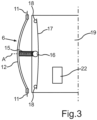
- Fig.3 shows a partial and perspective simplified view of the already in Fig.2 illustrated embodiment of the display device 2.
- the mirror 6 is in a deflection position, which can be realized by means of a change in the length of the first shape memory wire 17.
- the first shape memory wire 17 is arranged with a connecting element 16 on a coupling element 15, whereby a change in the length of the first shape memory wire 17 leads to a linear movement of the coupling element 15.
- the coupling element 15 is designed as a spring element, whereby forces acting on the coupling element 15 can be transmitted in a damping manner to the mirror 6, which is connected to the coupling element 15 via the coupling point 14.
- a linear force transmission of the coupling element 15 acts like a lever arm and causes the mirror 6 to pivot.
- a mirror plane for the virtual image 10 is linearly displaced when the position of the mirror 6 changes, without the virtual image 10 changing significantly in its position on the windshield 7, but in accordance with the desired setting.
Landscapes
- Engineering & Computer Science (AREA)
- Physics & Mathematics (AREA)
- Chemical & Material Sciences (AREA)
- Combustion & Propulsion (AREA)
- Transportation (AREA)
- Mechanical Engineering (AREA)
- General Physics & Mathematics (AREA)
- Optics & Photonics (AREA)
- Instrument Panels (AREA)
- Fittings On The Vehicle Exterior For Carrying Loads, And Devices For Holding Or Mounting Articles (AREA)
Description
- Die vorliegende Erfindung betrifft eine Anzeigevorrichtung für ein Kraftfahrzeug mit einem Gehäuse, welches eine in dem Gehäuse angeordnete Projektionseinrichtung zum Erzeugen eines virtuellen Bildes auf eine außerhalb des Gehäuses liegende und von einem Beobachter betrachtbare Projektionsfläche aufweist, die zumindest einen um eine Drehachse schwenkbar gelagerten Spiegel aufweist, der in einer Umlenkposition zum Umlenken eines von einer Lichtquelle der Projektionseinrichtung ausgegebenen Lichtes ausgebildet ist, und mit einer Justiervorrichtung zum Justieren der Umlenkposition des Spiegels durch Schwenken um die Drehachse. Darüber hinaus betrifft die vorliegende Erfindung ein Fahrerassistenzsystem mit einer solchen Anzeigevorrichtung. Ferner betrifft die vorliegende Erfindung ein Kraftfahrzeug mit einem solchen Fahrerassistenzsystem mit einer solchen Anzeigevorrichtung. Schließlich betrifft die folgende Erfindung ein Verfahren zum Justieren eines Spiegels einer Anzeigevorrichtung eines Kraftfahrzeugs.
- Aus dem Stand der Technik sind bereits Anzeigevorrichtungen für Kraftfahrzeuge bekannt, mit denen dem Fahrer bzw. den Insassen des Kraftfahrzeuges eine Anzeige bereitgestellt werden kann. Das Interesse richtet sich vorliegend insbesondere auf Kopf-oben-Anzeigevorrichtungen, welche auch als Head-Up-Anzeigevorrichtungen oder auch als Head-Up-Displays (HUD) bezeichnet werden. Eine derartige Anzeigevorrichtung umfasst üblicherweise ein Gehäuse, in welchem eine Projektionseinrichtung angeordnet ist. Ferner umfasst die Anzeigevorrichtung eine Optikeinrichtung, die beispielsweise eine oder mehrere Spiegel umfassen kann. Mit der Optikeinrichtung kann das von der Projektionseinrichtung abgestrahlte Licht auf eine Projektionsfläche projiziert werden. Die Projektionsfläche ist derart angeordnet, dass sie von einem Beobachter, insbesondere einem Fahrer des Kraftfahrzeuges, betrachtbar ist. Die Projektionsfläche kann eine semitransparente Spiegelfläche aufweisen. Diese semitransparente Spielfläche kann beispielsweise durch einen Bereich der Windschutzscheibe des Kraftfahrzeugs bereitgestellt werden. Die Optikeinrichtung kann einen zumindest einen um eine Drehachse schwenkbar gelagerten Spiegel aufweisen. Der drehbar gelagerte Spiegel dient insbesondere zum Umlenken eines von der Projektionseinrichtung ausgegebenen Lichtes. Die auf das Anzeigeelement, insbesondere der Windschutzscheibe, projizierte Information, welche von diesem reflektiert wird, wird mit einer durch das Anzeigeelement hindurchscheinenden Information aus einer hinter dem Anzeigeelement gelegenen Umgebung überlagert, wodurch ein virtuelles Bild bzw. eine virtuelle Anzeige bereitgestellt werden kann. Um dem Fahrer je nach Sitzposition, bzw. je nach Größe des Fahrers, eine optimale Sicht auf das virtuelle Bild zu ermöglichen, kann eine Augenbox, die auch "Eyebox" genannt wird, im Fahrzeug nachgeführt werden. Die Eyebox ist derjenige Bereich oder Sichtbereich, in dem der Augpunkt des Benutzers liegt, d.h. derjenige Bereich, in dem der Benutzer die angezeigte Information sehen kann. Das Umlenken des ausgegebenen Lichtes durch die Projektionseinrichtung dient zum Nachführen der Eyebox und wird mittels einer Justiervorrichtung am Spiegel realisiert. Stand der Technik ist z.B. in
WO 2015/180817 A1 zu finden. - Die Position der Anzeigevorrichtung ist üblicherweise vor dem Beobachter, insbesondere vor dem Fahrer des Kraftfahrzeuges, in einer Fahrgastzelle des Kraftfahrzeuges angeordnet. Es kann ein Bauraum im Bereich des Armaturenbretts, insbesondere im Bereich einer Kombihutze, bereitgestellt werden, in dem die Anzeigevorrichtung montiert werden kann und mittels einer Abdeckung, die vorzugsweise transparent ist, vor Schmutzpartikeln geschützt werden.
- Ein Verstellbereich der Eyebox ist üblicherweise sehr gering, da eine große Änderung des Nach-unten-Schau-Winkels, auch "Look-Down-Winkel" genannt, auch eine große Verschiebung des virtuellen Bildes nach sich zieht. Der Look-Down-Winkel ist der Winkel zwischen Horizont zu einem markierten Bild beziehungsweise der Winkel der Straßenoberfläche, der aus einer Augposition des Beobachters resultiert. Bei einer Veränderung des Look-Down-Winkels wird also eine Lage des virtuellen Bildes geändert, sodass eine dargestellte Information bei der virtuellen Anzeige verändert wird, so dass beispielsweise bei der Darstellung eines Navigationspfeiles dieser aus Sicht des Beobachters nicht mehr auf der Straße liegt. Des Weiteren darf das virtuelle Bild nicht zu weit in einen mittleren Sichtbereich des Fahrers gelangen, da sonst das virtuelle Bild eventuelle Hindernisse in der Umgebung des Fahrzeuges überblenden könnte. Ein zu weit unten im Sichtfeld des Beobachters gelegenes Bild könnte eine Überschneidung mit einer Spiegelung eines Kraftfahrzeugbauteils, beispielsweise einer Spiegelung des Armaturenbrettes, ergeben. Üblicherweise reicht daher eine Änderung von +/-2°aus, um die Lage des virtuellen Bildes an die Eyebox des Fahrers anzupassen. Der Verstellbereich muss ebenfalls möglichst "fließend" durchfahren werden, sodass ein Betrachter das Verstellen, insbesondere Justieren, nicht wahrnimmt. Des Weiteren wird dadurch eine hohe Variabilität verschiedener Lagen des virtuellen Bildes realisiert. Aus dem Stand der Technik sind hierzu Stellmotoren mit einem stark untersetzten Getriebe bekannt, mittels welcher das Justieren, insbesondere das Schwenken des Umlenkspiegels durchgeführt wird. Diese Stellmotoren mit dem stark untersetzten Getriebe sind oftmals sehr teuer und generieren Geräusche, welche von einem Beobachter als störend empfunden werden können.
- Bei diesen Kopf-oben-Anzeigevorrichtungen gibt es Ausführungen, bei welchen das virtuelle Bild an die Innenseite der Windschutzscheibe projiziert wird, so dass es vom Beobachter, insbesondere dem Fahrer, an der Innenseite betrachtet werden kann. Des Weiteren sind dazu unterschiedliche Ausführungen von Kopf-oben-Anzeigevorrichtungen bekannt, bei welchen das virtuelle Bild nicht auf die Windschutzscheibe projiziert wird, sondern mit einem zusätzlichen Spiegel, dem oben genannten Kombinierspiegel, der Kopf-oben-Anzeigevorrichtung zum Beobachter hin projiziert wird und somit bei insbesondere richtiger Einstellung des Kombinierspiegels in dessen Gesicht projiziert wird.
- Es ist Aufgabe der vorliegenden Erfindung, eine Lösung aufzeigen, wie das Schwenken des Spiegels um die Drehachse auf möglichst einfache und dennoch zuverlässige Weise erfolgen kann.
- Diese Aufgabe wird erfindungsgemäß durch eine Anzeigevorrichtung, durch ein Fahrerassistenzsystem, durch ein Kraftfahrzeug, sowie ein Verfahren mit den Merkmalen gemäß den jeweiligen unabhängigen Ansprüchen gelöst.
- Eine erfindungsgemäße Anzeigevorrichtung für ein Kraftfahrzeug umfasst ein Gehäuse. Ferner ist in dem Gehäuse eine Projektionseinrichtung zum Erzeugen eines virtuellen Bildes angeordnet. Ferner wird das virtuelle Bild auf eine außerhalb des Gehäuses liegende und von einem Beobachter betrachtbare Projektionsfläche projiziert. Es ist vorgesehen, dass die Projektionseinrichtung einen um eine Drehachse schwenkbar gelagerten Spiegel aufweist. Ferner ist der Spiegel in einer Umlenkposition zum Umlenken eines von der Lichtquelle der Projektionseinrichtung ausgegebenen Lichtes ausgebildet. Weiterhin umfasst die Anzeigevorrichtung eine Justiervorrichtung zum Justieren der Umlenkposition des Spiegels durch Schwenken um die Drehachse.
- Die Justiervorrichtung umfasst zumindest einen ersten Formgedächtnisdraht der mit dem Spiegel gekoppelt ist, sodass der Spiegel durch eine Längenveränderung des Formgedächtnisdrahtes um die Drehachse schwenkbar ist. Der Formgedächtnisdraht kann beispielsweise aus einer Formgedächtnislegierung, wie zum Beispiel Nickel-Titan, Nickel-Titankupfer, Kupfer-Zink oder weitere Formgedächtnislegierungen ausgebildet sein. Bevorzugt verformt sich das Formgedächtnismaterial in Abhängigkeit von der Eigentemperatur innerhalb eines bestimmten Temperaturintervalls, d.h. bei Temperaturänderungen unterhalb einer bestimmten unteren Temperatur findet keine phasenübergangsbedingte Verformung statt und ab Temperaturen oberhalb einer bestimmten oberen Temperatur findet ebenfalls keine phasenübergangsbedingte Formänderung mehr statt. Formgedächtnislegierungen sind bestimmte Metalle oder Metalllegierungen, die in zwei unterschiedlichen Kristallstrukturen existieren können. Während die meisten Metalle dieselbe Kristallstruktur bis zu ihrem Schmelzpunkt besitzen, haben Formgedächtnislegierungen, abhängig von der Temperatur, zwei unterschiedliche Strukturen (Phasen). Die Formwandlung bzw. Formänderung basiert damit auf dem Phasenübergang, d.h. der temperaturabhängigen Gitterumwandlung, zu einer dieser beiden Kristallstrukturen. Eine solche phasenübergangsbedingte Formänderung, wie zum Beispiel eine Ausdehnung, überschreitet dabei die herkömmliche, nicht phasenübergangsbedingte Wärmeausdehnung von Materialien um Größenordnungen, d.h. um einen Faktor mehrerer Zehnerpotenzen. Eine solche Temperaturänderung kann insbesondere mittels einer Bestromung des Formgedächtnisdrahtes realisiert werden. Durch den elektrischen Widerstand des Drahtes wird elektrische Energie in Wärmeenergie transformiert, was wiederum die gewünschte Längenänderung nach sich ziehen kann. Erfindungsgemäß ist vorgesehen, dass besonders Formgedächtnislegierungen, die eine Längenveränderung als Formänderung aufweisen, in der Justiervorrichtung angeordnet werden. Ein solcher Formgedächtnisdraht lässt sich auf einfache Weise bereitstellen und führt bei minimaler Geräuschentwicklung zu einem Schwenken des Spiegels.
- Durch die erfindungsgemäße Anzeigevorrichtung wird eine erweiterte Realität mit gleichbleibender Höhenlage des virtuellen Bildes beim Anpassen eines Sichtfeldes an benutzerspezifische Bedürfnisse ermöglicht. Somit wird die Darstellung der erweiterten Realität vor allem für beispielsweise sehr große oder sehr kleine Benutzer verbessert.
- Um die Augposition zu ermitteln kann die Anzeigevorrichtung eine Sensoreinrichtung zum Erfassen der Augposition aufweisen, sowie eine Steuereinrichtung, die dazu eingerichtet ist, in Abhängigkeit von einem Signal der Sensoreinrichtung die Justiervorrichtung, insbesondere den ersten Formgedächtnisdraht, zu steuern und somit ein Schwenken des Spiegels durchzuführen. Mit anderen Worten kann die Steuereinrichtung dazu eingerichtet sein, in Abhängigkeit von dem Signal der Sensoreinrichtung eine Drehlage des Spiegels zu verändern. Die Sensoreinrichtung kann dabei ein Bauteil oder eine Gerätekomponente der Anzeigevorrichtung sein, die einen entsprechenden Sensor aufweisen kann. Ein solcher Sensor kann beispielsweise als Kamera ausgebildet sein.
- In einer vorteilhaften Ausgestaltungsform kann die Justiervorrichtung ein separates Koppelelement aufweisen, welches mit dem ersten Formgedächtnisdraht und dem Spiegel gekoppelt ist, sodass mittels der Längenveränderung des ersten Formgedächtnisdrahtes eine Bewegung, insbesondere eine lineare Bewegung, des Koppelelementes bewirkbar ist und dadurch ein Verschwenken des Spiegels um die Drehachse zur Verstellung der Umlenkposition auftreten kann. Hierbei es vorteilhaft, dass nicht der Formgedächtnisdraht direkt mit dem Spiegel gekoppelt ist, und somit ein einfacherer Verbau des ersten Formgedächtnisdrahtes realisiert werden kann. Des Weiteren kann bei einem nötigen Austausch einer der Bauteile, das Bauteil einzeln ausgetauscht werden, was zu einer Kostenreduzierung und zu einer Materialeinsparung führt.
- In einer weiteren vorteilhaften Ausgestaltungsform kann das Koppelelement in Richtung seiner Längsachse betrachtet in sich selbst längenveränderlich ausgebildet sein. Mittels dieser Anordnung ist es möglich, nicht gewollte Rüttelbewegungen, welche über das Koppelelement übertragen werden können, zu dämpfen, sodass die Rüttelbewegungen gedämpft an den Spiegel übertragen werden können. Des Weiteren kann dadurch eine noch feinere Justierung realisiert werden, da zwei voneinander unabhängige und längenveränderliche Komponenten am Justiervorgang beteiligt werden können.
- Es hat sich als vorteilhaft erwiesen, dass das Koppelelement als ein Federelement ausgebildet ist. Das Federelement ist in sich längenveränderlich. Durch spezielle Materialien und "Drahtdicken" der Feder an sich, kann eine sehr exakte und bedarfsgenaue Federkraft bereitgestellt werden. Diese Federkraft kann dann dämpfend und haltend am Koppelelement angeordnet sein. Durch das Federelement kann auf einfache und günstige Weise eine Dämpfung der Rüttelbewegungen sowie eine Dämpfung einer Kraftübertragung vom ersten Formgedächtnisdraht auf den Spiegel durchgeführt werden. Des Weiteren kann das Federelement eine Rückholkraft auf den Spiegel bewirken, so dass dieser mittels des Federelementes in einer Position gehalten werden kann.
- Es hat sich ebenfalls als vorteilhaft erwiesen, wenn das Koppelelement als ein zweiter Formgedächtnisdraht ausgebildet ist. Mittels des zweiten Formgedächtnisdrahtes kann eine noch genauere Justage des Spiegels durchgeführt werden, da der erste Formgedächtnisdraht und der zweite Formgedächtnisdraht unterschiedlich angesteuert werden können, sodass beispielsweise die Vorteile unterschiedlicher Formgedächtnislegierungen kombiniert ausgenutzt werden können. Des Weiteren kann der zweite Formgedächtnisdraht eine Rückholkraft auf den Spiegel bewirken, so dass dieser mittels des zweiten Formgedächtnisdrahtes in einer Position gehalten werden kann.
- Gemäß einer bevorzugten Ausführungsform kann das Koppelelement mit dem ersten Formgedächtnisdraht durch ein separates Verbindungselement verbunden werden. Das Verbindungselement kann, beispielsweise durch eine längliche Form, insbesondere eine zylindrische Form, gewährleisten, dass eine Verbindung zwischen dem Koppelelement und dem ersten Formgedächtnisdraht realisiert werden kann. Des Weiteren kann bei einem nötigen Austausch, beispielsweise wegen Verschleißes eines der Komponenten, dieser sehr einfach realisiert werden, da die beweglichen Komponenten, insbesondere das Koppelelement und der erste Formgedächtnisdraht, voneinander entkoppelt sind und dadurch einfacher austauschbar sind.
- In einer weiteren vorteilhaften Ausgestaltungsform kann das Koppelelement außerhalb einer Reflexionsfläche des Spiegels mit dem Spiegel gekoppelt sein. Die Reflexionsfläche des Spiegels kann dadurch im Ganzen ausgenutzt werden, wodurch ein vorteilhafteres virtuelles Bild an die Windschutzscheibe projiziert werden kann. Die Anzeigevorrichtung kann dadurch auch materialsparender und kostengünstiger produziert werden, da gerade der Spiegel aufwendig in der Produktion ist. Daher ist vorteilhaft die gesamte zur Verfügung stehende Spiegelfläche als Reflexionsfläche nutzbar.
- In einer weiteren Ausgestaltung ist eine Koppelstelle zwischen dem Koppelelement und dem Spiegel nicht auf der Drehachse liegend ausgebildet. Insbesondere kann die Drehachse beabstandet zu einem ersten Rand und beabstandet zu einem zweiten gegenüberliegenden Rand des Spiegels verlaufend ausgebildet sein. Die Drehachse kann sich weiterhin zwischen die beiden Ränder verbindende, weiteren Ränder erstrecken, wobei die Koppelstelle zwischen dem Spiegel und dem Koppelelement in eine Verbindungslinie zwischen den Rändern zwischen Drehachse und einem Rand angeordnet ist, insbesondere an einem Rand ausgebildet ist. Durch diese Anordnung kann ein Hebelarm erzeugt werden, wodurch der Spiegel mit einem geringen Kraftaufwand bei gleichzeitig hoher Genauigkeit justiert werden kann.
- In einer weiteren vorteilhaften Ausgestaltungsform kann die Justiervorrichtung Halteelemente aufweisen, an denen der Formgedächtnisdraht befestigt ist, wobei die Halteelemente an einer Platine angeordnet sind. Die Halteelemente können dabei als elektrische Kontakte für die Bestromung des ersten Formgedächtnisdrahtes dienen. Durch die Anbringung der Halteelemente an die Platine kann bauraumsparend die Justiervorrichtung realisiert werden. Des Weiteren können benötigte Schaltelemente, die zur Steuerung der Justiervorrichtung dienen können, auf der bereits vorhandenen Platine angeordnet werden. Durch die Halteelemente kann der erste Formgedächtnisdraht in einer mechanisch vorgespannten Position gehalten werden, so dass der erste Formgedächtnisdraht durch die Schwerkraft nur minimal in seiner Position beeinträchtigt wird. Dadurch kann die Ansteuerung bzw. die Längenänderung des ersten Formgedächtnisdrahtes direkt in die gewünschte Richtung, nämlich in Längsrichtung des Koppelelementes realisiert werden. Somit kann ein Schwenken um die Drehachse erfolgen, die vorzugsweise bei einer eingebauten Anzeigevorrichtung in einer Fahrzeugquerrichtung verlaufen kann. Die Halteelemente können als Stifte ausgebildet sein.
- Gemäß einer weiteren vorteilhaften Ausgestaltungsform kann die Justiervorrichtung eine Arretiervorrichtung aufweisen, mit welcher der Spiegel in seiner justierten Umlenkposition arretierbar ist. Durch diese Anordnung kann der Spiegel nach einer Justage in die Umlenkposition arretiert werden und somit kann nach der Justage insbesondere der erste Formgedächtnisdraht wieder in eine Ursprungsposition, die einer Position entspricht, die der erste Formgedächtnisdraht aufweist wenn er nicht bestromt ist, zurückgeführt werden, ohne dass der Spiegel sich in seiner Position verändert. Dies kann dazu führen, dass sowohl elektrische Energie eingespart werden kann als auch ein Verschleiß des ersten Formgedächtnisdrahtes verringert wird.
- Es hat sich ebenfalls als vorteilhaft erwiesen, wenn die Arretiervorrichtung eine an der Drehachse angreifende Kupplung umfasst, durch welche der Spiegel in einer eingestellten Umlenkposition arretierbar ist. Mittels dieser Anordnung ist eine bauraumsparende und bauteilsparende Arretierung des Spiegels in einer eingestellten Umlenkposition möglich.
- Gemäß einer weiteren bevorzugten Ausführungsform ist die Justiervorrichtung derart ausgebildet, dass der Spiegel in seiner Umlenkposition um kleiner +/-1 ,8°um eine Grundstellung veränderbar ist. Es hat sich besonders vorteilhaft gezeigt, dass mittels einer Umlenkposition um kleiner +/-1 ,8°um eine Gru ndstellung der bevorzugte Stellbereich einer Eyebox von +/-2° realisiert werd en kann. Bei einer Veränderung der Umlenkposition wird also eine Lage des virtuellen Bildes geändert, sodass eine dargestellte Information bei einer virtuellen Anzeige verändert wird, so dass beispielsweise bei der Darstellung eines Navigationspfeiles dieser aus Sicht des Beobachters nicht mehr auf der Straße liegt. Des Weiteren darf das virtuelle Bild nicht zu weit in einen mittleren Sichtbereich des Fahrers gelangen, da sonst das virtuelle Bild eventuelle Hindernisse in der Umgebung des Fahrzeuges überblenden könnte. Ein zu weit unten im Sichtfeld des Beobachters gelegenes Bild könnte eine Überschneidung mit einer Spiegelung eines Fahrzeugbauteils, beispielsweise einer Spiegelung des Armaturenbretts, ergeben.
- Ein erfindungsgemäßes Fahrerassistenzsystem für ein Kraftfahrzeug umfasst eine erfindungsgemäße Anzeigevorrichtung.
- Ein erfindungsgemäßes Kraftfahrzeug umfasst ein erfindungsgemäßes Fahrerassistenzsystem. Das Kraftahrzeug ist insbesondere als Personenkraftwagen ausgebildet.
- Ein erfindungsgemäß Verfahren dient zum Justieren eines Spiegels einer Anzeigevorrichtung eines Kraftfahrzeugs. Hierbei weist die Anzeigevorrichtung ein Gehäuse auf, welches eine in dem Gehäuse angeordnete Projektionseinrichtung zum Erzeugen eines virtuellen Bildes auf eine außerhalb des Gehäuses liegende und von einem Beobachter betrachtbare Projektionsfläche aufweist, und mit zumindest einem um eine Drehachse schwenkbar gelagerten Spiegel, der in einer Umlenkposition zum Umlenken eines von einer Lichtquelle der Projektionseinrichtung ausgegebenen Lichtes ausgebildet ist und mit einer Justiervorrichtung zum Justieren der Umlenkposition des Spiegels durch Schwenken um die Drehachse ausgebildet wird. Der Spiegel wird mit einem ersten Formgedächtnisdraht der Justiervorrichtung gekoppelt. Durch eine Längenänderung des ersten Formgedächtnisdrahtes wird eine Umlenkposition des Spiegels durch Schwenken des Spiegels um die Drehachse eingestellt.
- Die Steuereinrichtung kann ein entsprechendes Steuersignal empfangen, das einen erwünschtes Umlenken und damit einen gewünschten Höhenversatz eines Sichtbereiches um die Augposition des Beobachters beschreibt und in Abhängigkeit von dem Steuersignal ein Schwenken des Spiegels zum Justieren um die Drehachse veranlassen. Das Steuersignal kann beispielsweise von einer Bedienvorrichtung des Kraftfahrzeuges oder von der Sensoreinrichtung erzeugt werden. Mittels der Sensoreinrichtung kann ein automatisches Anpassen der Eyebox realisiert werden.
- Die mit Bezug auf die erfindungsgemäße Anzeigevorrichtung vorgestellten bevorzugten Ausführungsformen und deren Vorteile gelten entsprechend für das erfindungsgemäße Fahrerassistenzsystem, das erfindungsgemäße Kraftfahrzeug sowie das erfindungsgemäße Verfahren.
- Weitere Merkmale der Erfindung ergeben sich aus den Ansprüchen, den Figuren und der Figurenbeschreibung. Die vorstehend in der Beschreibung genannten Merkmale und Merkmalskombinationen, sowie die nachfolgend in der Figurenbeschreibung genannten und/oder in den Figuren alleine gezeigten Merkmale und Merkmalskombinationen sind nicht nur der jeweils angegebenen Kombination, sondern auch in anderen Kombinationen oder in Alleinstellung verwendbar, ohne den Rahmen der Erfindung zu verlassen. Es sind somit auch Ausführungen von der Erfindung als umfasst und offenbart anzusehen, die in den Figuren nicht explizit gezeigt und erläutert sind, jedoch durch separierte Merkmalskombinationen aus den erläuterten Ausführungen hervorgehen und erzeugbar sind. Es sind auch Ausführungen und Merkmalskombinationen als offenbart anzusehen, die somit nicht alle Merkmale eines ursprünglich formulierten unabhängigen Anspruchs aufweisen.
- Die Erfindung wird nur anhand von bevorzugten Ausführungsbeispielen sowie unter Bezugnahme auf die beigefügten Zeichnungen erläutert.
- Dabei zeigen:
- Fig. 1
- eine ausschnittsweise Darstellung eines Kraftfahrzeuges, welches eine Anzeigevorrichtung gemäß einer Ausführungsform der vorliegenden Erfindung aufweist;
- Fig. 2
- eine schematische und ausschnittsweise Darstellung der Anzeigevorrichtung mit einem schwenkbaren Spiegel; und
- Fig. 3
- eine ausschnittsweise und schematische Draufsicht auf die Anzeigevorrichtung.
- In den Figuren werden gleiche und funktionsgleiche Elemente mit den gleichen Bezugszeichen versehen.
-
Fig. 1 zeigt eine ausschnittsweise Darstellung eines Kraftfahrzeugs 1 gemäß einer Ausführungsform der vorliegenden Erfindung. Das Kraftfahrzeug 1 ist in dem vorliegenden Ausführungsbeispiel als Personenkraftwagen ausgebildet. Das Kraftfahrzeug 1 umfasst allgemein eine Anzeigevorrichtung 2 zur Projektion eines virtuellen Bilds 10 auf eine vorrichtungsexterne Projektionsfläche. Die Anzeigevorrichtung 2 ist in dem vorliegenden Ausführungsbeispiel als Kopf-Oben-Anzeigevorrichtung bzw. Head-Up-Display ausgebildet. Die Anzeigevorrichtung 2 kann insbesondere an einer Kombihutze des Kraftfahrzeuges 1 angeordnet sein, welche wiederum an einem Armaturenbrett angeordnet sein kann. - Die Anzeigevorrichtung 2 umfasst eine Projektionseinrichtung 3. Mittels der Projektionseinrichtung 3 kann insbesondere Licht 4 abgestrahlt werden. Insbesondere kann mit der Projektionseinrichtung 3 ein Bild bereitgestellt werden. Die Projektionseinrichtung 3 kann beispielsweise einen entsprechenden Bildschirm aufweisen, mit dem Licht 4 von zunächst einer Lichtquelle der Projektionseinrichtung 3 zur Erzeugung des virtuellen Bilds 10 verarbeitet wird und dann ein Bild bereitgestellt werden kann. Darüber hinaus umfasst die Anzeigevorrichtung 2 eine Optikeinrichtung 5. Die Optikeinrichtung 5 umfasst vorliegend einen Spiegel 6. Das von der Projektionseinrichtung 3 abgestrahlte Licht 4 in Form des virtuellen Bilds 10 trifft zunächst auf den Spiegel 6 und anschließend auf ein Anzeigeelement bzw. auf eine vorrichtungsexterne Projektionsfläche, welches bzw. welche insbesondere eine Windschutzscheibe 7 des Kraftfahrzeugs 1 darstellt. Die Projektionseinrichtung 3 und die Optikeinrichtung 5 sind vorliegend innerhalb eines Armaturenbretts des Kraftfahrzeugs 1 angeordnet.
- Die Windschutzscheibe 7 weist eine Spiegelfläche auf und ist semi-transparent ausgebildet. Das Licht 4, das von der Projektionseinrichtung 3 abgestrahlt wird, wird mittels der Optikeinrichtung 5 auf die Windschutzscheibe 7 projiziert. Ferner wird das Licht 4, das auf die Windschutzscheibe 7 projiziert wird, zu den Augen 9 eines Beobachters, insbesondere eines Fahrers 8, des Kraftfahrzeugs 1 reflektiert. Somit überlagert sich diese Anzeige mit dem Licht, das von einem Umgebungsbereich U des Kraftfahrzeugs 1 zu den Augen 9 des Betrachters gelangt, mit dem Licht 4, das auf die Windschutzscheibe 7 projiziert wird. Für den Betrachter, der insbesondere den Fahrer 8 des Kraftfahrzeugs 1 ist, ergibt sich somit eine virtuelle Anzeige bzw. ein virtuelles Bild 10.
- Das virtuelle Bild 10 kann insbesondere so auf die Windschutzscheibe 7 projiziert werden, dass es in einem unteren Sichtbereich des Fahrers 8 dargestellt wird. Vorzugsweise befindet sich die Position in einem unteren Sichtbereich des Fahrers 8 dort, wo keine Spiegelung von anderen Kraftfahrzeugbauteilen, beispielsweise eine Spiegelung des Armaturenbretts, für den Fahrer 8 auftreten. Vorzugsweise befindet sich das virtuelle Bild 10 weiterhin in einem Sichtbereich, so dass alle Hindernisse, insbesondere einer Straße, von dem Fahrer 8 noch erkennbar.
-
Fig. 2 zeigt ausschnittsweise und schematisch die Anzeigevorrichtung 2 in einer Perspektivansicht. Der Spiegel 6 der Projektionseinrichtung 3 ist dabei insbesondere um eine Drehachse 11 schwenkbar gelagert. Die Drehachse 11 des Spiegels 6 verläuft beabstandet zu einem oberen Rand 12 und einem unteren Rand 13, insbesondere parallel zu dem oberen Rand 12 und/oder dem unteren Rand 13. An dem unteren Rand 13 ist vorteilhafterweise eine Koppelstelle 14 angeordnet, die insbesondere außerhalb einer Reflexionsfläche 24 des Spiegels 6 ausgebildet ist. Über die Koppelstelle 14 ist der Spiegel 6 mit einem Koppelelement 15 verbunden. Das Koppelelement 15 ist beispielsweise als Federelement ausgebildet, welches somit in Richtung seiner Längsachse A in sich selbst längenveränderlich ist. Es sind aber auch weitere Ausführungsformen möglich, insbesondere ist eine weitere Ausführungsform als ein zweiter Formgedächtnisdraht möglich, der auch entsprechend in sich selbst längenveränderlich ist. Das Koppelelement 15, das an einem ersten Ende mit der Koppelstelle 14 verbunden ist, ist an einer zweiten Stelle mit einem Verbindungselement 16 verbunden. Das Verbindungselement 16 kann hier insbesondere zylinderförmig ausgebildet sein, wodurch eine größere Verbindungsfläche realisiert werden kann, sodass ein erster Formgedächtnisdraht 17 einen Kontakt mit dem Verbindungselement 16 herstellen kann, dieser aber dennoch Bewegungsfreiheiten hat. - Der erste Formgedächtnisdraht 17 ist in der Ausgestaltungsform derart positioniert, dass dieser in verkürzter Position zumindest größtenteils parallel zu der Drehachse 11 des Spiegels 6 verläuft. Der erste Formgedächtnisdraht 17 ist an zwei stiftartigeHalteelemente 18 angeordnet, die zum einen zum Halten und Vorspannen des ersten Formgedächtnisdrahtes 17 dienen, aber zum anderen auch mit einer Platine 19 verbunden sind und elektrisch leitend sind. An den weiteren Rändern 23 des Spiegels 6 sind jeweilige Arretiervorrichtungen 20 angeordnet, die zum Arretieren des Spiegels 6 in einer Umlenkposition ausgebildet sind. Der Spiegel 6 selbst wird mittels einer Halterung 21 an einem in dieser Figur nicht gezeigten Gehäuse der Anzeigevorrichtung 2 gehalten.
- Die Halterung 21 ist in diesem Ausführungsbeispiel an der Drehachse 11 des Spiegels 6 angeordnet.
- Eine Steuereinrichtung 22 auf der Platine 19 dient zum Ansteuern, insbesondere zur Bestromung des ersten Formgedächtnisdrahts 17. Die Halteelemente 18 können dabei elektrisch durch die Steuereinrichtung 22 angesteuert werden, wodurch der erste Formgedächtnisdraht 17 eine Längenänderung vollziehen kann. Findet beispielsweise aus der hier dargestellten Position des ersten Formgedächtnisdrahts 17 eine Verkürzung des ersten Formgedächtnisdrahts 17 statt, so wird eine Kraft auf das Verbindungselement 16 übertragen welches wiederum die Kraft an das Koppelelement 15 weitergibt. Das Koppelelement 15 ist hierbei als ein Federelement ausgebildet, und kann die Kraft dämpfend mittels der Koppelstelle 14 an den unteren Rand 13 des Spiegels 6 übertragen. Ein zwischen der Drehachse 11 und dem unteren Rand 13 entstandener Hebelarm führt von einer linearen Kraft, die von dem Koppelelement 15 übertragen wird, zu einer Drehbewegung um die Drehachse 11 des Spiegels 6.
- Eine optionale Sensoreinrichtung im Kraftfahrzeug 1 kann zum Beispiel eine Augenhöhe oder einen Augpunkt eines Beobachters, insbesondere des Fahrers 8 ermitteln. Beispielhaft kann die Sensoreinrichtung als Kamera, die an einem Dachhimmel oder an einem der Windschutzscheibe 7 angeordneten Innenspiegel des Kraftfahrzeuges 1 angeordnet sein kann, ausgestaltet und dazu eingerichtet sein, eine räumliche Lage eines Auges 9 des Fahrers 8 zu erfassen. Über eine drahtlose oder drahtgebundene Datenkommunikationseinrichtung kann das Sensorsignal an die Steuereinrichtung 22 übertragen werden. Die Steuereinrichtung 22 kann dann in Abhängigkeit des Sensorsignals, also in Abhängigkeit der Lage des Auges 9, den ersten Formgedächtnisdraht 17 ansteuern und somit den Spiegel 6 in eine bevorzugte Position schwenken. Zusätzlich oder alternativ kann die Steuereinrichtung 22 ein Steuersignal von einer Bedieneinrichtung empfangen, die einen gewünschten Höhenversatz des Sichtbereichs um die Augposition des Fahrers 8 beschreibt. Hierzu kann der Fahrer 8 beispielsweise mit Hilfe der Bedieneinrichtung eines Kombiinstrumentes oder eines Infotainmentsystems eine Verstellung des Sichtbereiches eingeben.
- Das Schwenken des Spiegels 6 kann um die Drehachse 11 erfolgen, die vorzugsweise bei einer eingebauten Anzeigevorrichtung 2 in einer Kraftfahrzeugquerrichtung verlaufen kann. Im diesem Ausführungsbeispiel verläuft die Drehachse 11 senkrecht zu einer Bildebene. Durch die schwenkbare Lagerung des Spiegels 6 innerhalb des nicht gezeigten Gehäuses wird eine Spiegelebene für das virtuelle Bild 10 bei Änderung der Spiegelposition linear verschoben, ohne dass sich das virtuelle Bild 10 in seiner Lage auf der Projektionsfläche, insbesondere der Windschutzscheibe 7, signifikant ändert. Durch die lineare Verschiebung der Spiegelungsebene kann eine Verlagerung der Eyebox erreicht werden. Dadurch kann das virtuelle Bild 10 bezogen auf die Straße auf gleicher Höhe gehalten werden.
- Durch diese Schwenkbewegung des Spiegels 6 (zwischen +/-1,8°) kann das virtuelle Bild 10 um +/-2°auf der Windschutzscheibe 7 verschoben werden, wodurch eine Anpassung der Eyebox an den Beobachter, insbesondere den Fahrer 8, realisiert werden kann.
-
Fig. 3 zeigt eine ausschnittsweise und perspektivische vereinfachte Ansicht der bereits inFig. 2 dargestellten Ausführungsform der Anzeigevorrichtung 2. Der Spiegel 6 befindet sich dabei in einer Umlenkposition, welche mittels einer Längenänderung des ersten Formgedächtnisdrahtes 17 realisiert werden kann. Der erste Formgedächtnisdraht 17 ist dabei mit einem Verbindungselement 16 an einem Koppelelement 15 angeordnet, wodurch eine Längenänderung des ersten Formgedächtnisdrahtes 17 zu einer linearen Bewegung des Koppelelementes 15 führt. Das Koppelelement 15 ist hierbei als Federelement ausgebildet, wodurch auf das Koppelelement 15 wirkende Kräfte dämpfend an den Spiegel 6, welcher über die Koppelstelle 14 mit dem Koppelelement 15 verbunden ist, dämpfend übertragen werden können. Eine lineare Kraftübertragung des Koppelelements 15 wirkt dabei wie ein Hebelarm, und bewirkt dabei eine Schwenkung des Spiegels 6. Durch die schwenkbare Lagerung des Spiegels 6 innerhalb eines nicht dargestellten Gehäuses wird eine Spiegelebene für das virtuelle Bild 10 bei Änderung der Position des Spiegels 6 linear verschoben, ohne dass sich das virtuelle Bild 10 in seiner Lage auf der Windschutzscheibe 7 signifikant, jedoch entsprechend der gewünschten Einstellung, ändert
Claims (14)
- Anzeigevorrichtung (2) für ein Kraftfahrzeug (1) mit einem Gehäuse, welches eine in dem Gehäuse angeordnete Projektionseinrichtung (3) zum Erzeugen eines virtuellen Bildes (10) auf eine außerhalb des Gehäuses liegende und von einem Beobachter betrachtbare Projektionsfläche aufweist, die zumindest einen um eine Drehachse (11) schwenkbar gelagerten Spiegel (6) aufweist, der in einer Umlenkposition zum Umlenken eines von einer Lichtquelle der Projektionseinrichtung (3) ausgegebenen Lichtes (4) ausgebildet ist, und mit einer Justiervorrichtung zum Justieren der Umlenkposition des Spiegels (6) durch Schwenken um die Drehachse (11),wobei die Justiervorrichtung zumindest einen ersten Formgedächtnisdraht (17) aufweist der mit dem Spiegel (6) gekoppelt ist, so dass der Spiegel (6) durch eine Längenveränderung des ersten Formgedächtnisdrahtes (17) um die Drehachse (11) schwenkbar ist und, dassdie Justiervorrichtung ein separates Koppelelement (15) aufweist, welches mit dem ersten Formgedächtnisdraht (17) und dem Spiegel (6) gekoppelt ist, so dass mittels der Längenveränderung des ersten Formgedächtnisdrahtes (17) eine Bewegung, insbesondere eine lineare Bewegung, des Koppelelementes (15) bewirkbar ist und dadurch ein Verschwenken des Spiegels (6) um die Drehachse (11) zur Verstellung der Umlenkposition auftritt und der Formgedächtnisdraht (17) derart positioniert ist, dass dieser in verkürzter Position zumindest größtenteils parallel zu der Drehachse (11) des Spiegels (6) verläuft.
- Anzeigevorrichtung (2) nach Anspruch 1,
dadurch gekennzeichnet, dass
das Koppelelement (15) in Richtung seiner Längsachse (A) betrachtet in sich selbst längenveränderlich ausgebildet ist. - Anzeigevorrichtung (2) nach Anspruch 2,
dadurch gekennzeichnet, dass
das Koppelelement (15) als ein Federelement ausgebildet ist. - Anzeigevorrichtung (2) nach Anspruch 2,
dadurch gekennzeichnet, dass
das Koppelelement (15) als ein zweiter Formgedächtnisdraht ausgebildet ist. - Anzeigevorrichtung (2) nach Anspruch 1 bis 4,
dadurch gekennzeichnet, dass
das Koppelelement (15) mit dem ersten Formgedächtnisdraht (17) durch ein separates Verbindungselement (16) verbunden ist. - Anzeigevorrichtung (2) nach Anspruch 1 bis 5,
dadurch gekennzeichnet, dass
das Koppelelement (15) außerhalb einer Reflexionsfläche (24) des Spiegels (6) mit dem Spiegel (6) gekoppelt ist. - Anzeigevorrichtung (2) nach Anspruch 1 bis 6
dadurch gekennzeichnet, dass
eine Koppelstelle (14) zwischen dem Koppelelement (15) und dem Spiegel (6) nicht auf der Drehachse (11) iegend ausgebildet ist. - Anzeigevorrichtung (2) nach einem vorhergehenden Anspruch,
dadurch gekennzeichnet, dass
die Justiervorrichtung Halteelemente (18) aufweist an denen der erste Formgedächtnisdraht (17) befestigt ist, wobei die Halteelemente (18) an einer Platine (19) angeordnet sind. - Anzeigevorrichtung (2) nach einem vorhergehenden Anspruch,
dadurch gekennzeichnet, dass
die Justiervorrichtung eine Arretiervorrichtung (20) aufweist, mit welcher der Spiegel (6) in seiner justierten Umlenkposition arretierbar ist. - Anzeigevorrichtung (2) nach Anspruch 9,
dadurch gekennzeichnet, dass
die Arretiervorrichtung (20) eine an der Drehachse (11) angreifende Kupplung umfasst, durch welche der Spiegel (6) in einer eingestellten Umlenkposition arretierbar ist. - Anzeigevorrichtung (2) nach einem vorhergehenden Anspruch,
dadurch gekennzeichnet, dass
die Justiervorrichtung derart ausgebildet ist, dass der Spiegel (6) in seiner Umlenkposition um kleiner ± 1,8° um eine Grundstellung veränderbar ist. - Fahrerassistenzsystem, welches eine Anzeigevorrichtung (2) gemäß den Ansprüchen 1 bis 11 aufweist.
- Kraftfahrzeug (1), welches ein Fahrerassistenzsystem gemäß Patentanspruch 12 aufweist.
- Verfahren zum Justieren eines Spiegels (6) einer Anzeigevorrichtung (2) eines Kraftfahrzeuges (1), bei welchem die Anzeigevorrichtung (2) mit einem Gehäuse, welches eine in dem Gehäuse angeordnete Projektionseinrichtung (3) zum Erzeugen eines virtuellen Bildes (10) auf eine außerhalb des Gehäuses liegende und von einem Beobachter betrachtbare Projektionsfläche aufweist, und mit zumindest einem um eine Drehachse (11) schwenkbar gelagerten Spiegel (6), der in einer Umlenkposition zum Umlenken eines von einer Lichtquelle der Projektionseinrichtung (3) ausgegebenen Lichtes (4) ausgebildet ist, und mit einer Justiervorrichtung zum Justieren der Umlenkposition des Spiegels (6) durch Schwenken um die Drehachse (11) ausgebildet wird,
dadurch gekennzeichnet, dass
der Spiegel (6) mit einem ersten Formgedächtnisdraht (17) der Justiervorrichtung gekoppelt wird, wobei Formgedächtnisdraht (17) derart positioniert ist, dass dieser in verkürzter Position zumindest größtenteils parallel zu der Drehachse (11) des Spiegels (6) verläuft, und durch eine Längenänderung des ersten Formgedächtnisdrahts (17) eine Umlenkposition des Spiegels (6) durch Schwenken des Spiegels (6) um die Drehachse (11) eingestellt wird, wobei die Justiervorrichtung ein separates Koppelelement (15) aufweist, welches mit dem ersten Formgedächtnisdraht (17) und dem Spiegel (6) gekoppelt ist, so dass mittels der Längenveränderung des ersten Formgedächtnisdrahtes (17), insbesondere linear, das Koppelelement (15) bewegt wird ist und dadurch der Spiegel (6) um die Drehachse (11) zur Verstellung der Umlenkposition verschwenkt wird.
Applications Claiming Priority (2)
| Application Number | Priority Date | Filing Date | Title |
|---|---|---|---|
| DE102016109872.8A DE102016109872A1 (de) | 2016-05-30 | 2016-05-30 | Anzeigevorrichtung, Fahrerassistenzsystem und Verfahren für ein Kraftfahrzeug, sowie Kraftfahrzeug |
| PCT/EP2017/061824 WO2017207275A1 (de) | 2016-05-30 | 2017-05-17 | Anzeigevorrichtung, fahrerassistenzsystem und verfahren für ein kraftfahrzeug, sowie kraftfahrzeug |
Publications (2)
| Publication Number | Publication Date |
|---|---|
| EP3465325A1 EP3465325A1 (de) | 2019-04-10 |
| EP3465325B1 true EP3465325B1 (de) | 2024-07-24 |
Family
ID=58739040
Family Applications (1)
| Application Number | Title | Priority Date | Filing Date |
|---|---|---|---|
| EP17724545.3A Active EP3465325B1 (de) | 2016-05-30 | 2017-05-17 | Anzeigevorrichtung, fahrerassistenzsystem und verfahren für ein kraftfahrzeug, sowie kraftfahrzeug |
Country Status (6)
| Country | Link |
|---|---|
| US (1) | US11092807B2 (de) |
| EP (1) | EP3465325B1 (de) |
| JP (1) | JP6685435B2 (de) |
| CN (1) | CN109416473B (de) |
| DE (1) | DE102016109872A1 (de) |
| WO (1) | WO2017207275A1 (de) |
Families Citing this family (5)
| Publication number | Priority date | Publication date | Assignee | Title |
|---|---|---|---|---|
| KR20200045359A (ko) * | 2018-10-22 | 2020-05-04 | 삼성전자주식회사 | 투시형 디스플레이 장치 |
| DE102019122574A1 (de) * | 2019-08-22 | 2021-02-25 | Valeo Schalter Und Sensoren Gmbh | Einstellvorrichtung, Einstelleinheit, Head-Up-Display und Kraftfahrzeug |
| DE102020132549A1 (de) * | 2020-12-08 | 2022-06-09 | Valeo Schalter Und Sensoren Gmbh | Reflexionsvorrichtung, Reflexionselement-Baugruppe, Head-Up-Display und Kraftfahrzeug |
| DE102021123187A1 (de) * | 2021-09-08 | 2023-03-09 | Valeo Schalter Und Sensoren Gmbh | Spiegelvorrichtung für ein Head-up-Display mit spezifischem Drehlager zwischen einem Träger und einer dazu separaten Lagereinheit, sowie Head-up-Display und Kraftfahrzeug |
| US20230130201A1 (en) * | 2021-10-26 | 2023-04-27 | GM Global Technology Operations LLC | Driver seat and side mirror-based localization of 3d driver head position for optimizing driver assist functions |
Citations (3)
| Publication number | Priority date | Publication date | Assignee | Title |
|---|---|---|---|---|
| JPS57121777U (de) * | 1981-01-26 | 1982-07-29 | ||
| EP0186391A2 (de) * | 1984-12-13 | 1986-07-02 | Donnelly Mirrors Limited | Rückspiegelanordnung für Kraftfahrzeuge mit einem lichtdämpfenden Fluid |
| EP2637156A1 (de) * | 2010-11-05 | 2013-09-11 | EIZO Corporation | Mechanismus zur betätigung einer sensoreinheit und flüssigkristallanzeigemechanismus zur betätigung einer sensoreinheit |
Family Cites Families (15)
| Publication number | Priority date | Publication date | Assignee | Title |
|---|---|---|---|---|
| US5394203A (en) * | 1994-06-06 | 1995-02-28 | Delco Electronics Corporation | Retracting head up display with image position adjustment |
| IT1305590B1 (it) * | 1998-12-23 | 2001-05-09 | Magneti Marelli Spa | Specchio retrovisore per autoveicoli con dispositivo attuatoreanti-abbagliamento, a memoria di forma. |
| JP4611566B2 (ja) * | 2001-05-11 | 2011-01-12 | 矢崎総業株式会社 | ヘッドアップディスプレイ用コンバイナの収納方法及びヘッドアップディスプレイ用コンバイナ収納装置 |
| WO2003014789A2 (en) * | 2001-07-05 | 2003-02-20 | International Business Machines Coporation | Microsystem switches |
| JP2005533956A (ja) | 2002-07-24 | 2005-11-10 | エム2・メディカル・アクティーゼルスカブ | 形状記憶合金アクチュエータ |
| EP1912091A1 (de) * | 2006-09-29 | 2008-04-16 | C.R.F. Societa Consortile per Azioni | Head-Up-Display für ein Kraftfahrzeug |
| JP5878869B2 (ja) | 2010-08-20 | 2016-03-08 | 株式会社青電舎 | 衝撃駆動型アクチュエータ |
| DE102011118853A1 (de) | 2011-08-18 | 2013-02-21 | Johnson Controls Gmbh | Anzeigevorrichtung |
| DE102012018397A1 (de) * | 2011-09-19 | 2013-03-21 | Ulrich Wild | Drehsteller |
| EP2927780A1 (de) * | 2014-04-03 | 2015-10-07 | SMR Patents S.à.r.l. | Schwenkbarer Innenspiegel für ein Fahrzeug |
| FR3021417B1 (fr) | 2014-05-20 | 2017-10-06 | Peugeot Citroen Automobiles Sa | Dispositif d'affichage |
| DE102014008201A1 (de) * | 2014-05-30 | 2015-12-03 | Audi Ag | Anzeigeeinrichtung für ein Kraftfahrzeug und Kraftfahrzeug |
| JP2016044672A (ja) * | 2014-08-22 | 2016-04-04 | トキコーポレーション株式会社 | アクチュエータ機構および鉄道模型用連結器および人型ロボット用表情筋駆動装置。 |
| DE102014118181A1 (de) * | 2014-12-09 | 2016-06-09 | Valeo Schalter Und Sensoren Gmbh | Anzeigevorrichtung für ein Kraftfahrzeug mit drehbar gelagerter Spiegeleinrichtung, Kraftfahrzeug sowie Verfahren |
| DE102015203787A1 (de) * | 2015-03-03 | 2016-09-08 | Robert Bosch Gmbh | Vorrichtung zum Verstellen eines Spiegels, Head-Up-Display |
-
2016
- 2016-05-30 DE DE102016109872.8A patent/DE102016109872A1/de not_active Withdrawn
-
2017
- 2017-05-17 CN CN201780042772.3A patent/CN109416473B/zh active Active
- 2017-05-17 US US16/305,554 patent/US11092807B2/en active Active
- 2017-05-17 EP EP17724545.3A patent/EP3465325B1/de active Active
- 2017-05-17 JP JP2018562616A patent/JP6685435B2/ja active Active
- 2017-05-17 WO PCT/EP2017/061824 patent/WO2017207275A1/de not_active Ceased
Patent Citations (3)
| Publication number | Priority date | Publication date | Assignee | Title |
|---|---|---|---|---|
| JPS57121777U (de) * | 1981-01-26 | 1982-07-29 | ||
| EP0186391A2 (de) * | 1984-12-13 | 1986-07-02 | Donnelly Mirrors Limited | Rückspiegelanordnung für Kraftfahrzeuge mit einem lichtdämpfenden Fluid |
| EP2637156A1 (de) * | 2010-11-05 | 2013-09-11 | EIZO Corporation | Mechanismus zur betätigung einer sensoreinheit und flüssigkristallanzeigemechanismus zur betätigung einer sensoreinheit |
Also Published As
| Publication number | Publication date |
|---|---|
| DE102016109872A1 (de) | 2017-11-30 |
| JP2019519811A (ja) | 2019-07-11 |
| US20200326541A1 (en) | 2020-10-15 |
| JP6685435B2 (ja) | 2020-04-22 |
| WO2017207275A1 (de) | 2017-12-07 |
| EP3465325A1 (de) | 2019-04-10 |
| CN109416473B (zh) | 2021-06-15 |
| US11092807B2 (en) | 2021-08-17 |
| CN109416473A (zh) | 2019-03-01 |
Similar Documents
| Publication | Publication Date | Title |
|---|---|---|
| EP2033049B1 (de) | Kamerasystem für ein kraftfahrzeug | |
| EP3585638B1 (de) | Kraftfahrzeug mit einer anzeigeanordnung und verfahren zum betreiben einer anzeigeanordnung eines kraftfahrzeugs | |
| EP3551490B1 (de) | Anzeigevorrichtung für ein kraftfahrzeug | |
| DE10131459B4 (de) | Video-Überwachungsanordnung für Kraftfahrzeuge | |
| EP3465325A1 (de) | Anzeigevorrichtung, fahrerassistenzsystem und verfahren für ein kraftfahrzeug, sowie kraftfahrzeug | |
| EP2616872B1 (de) | Head-up-display mit einem projektionsschirm und einer vorrichtung zur bewegung und positionierung eines projektionsschirms und verfahren zum betrieb eines solchen head-up-displays | |
| EP3847498B1 (de) | Anzeigevorrichtung mit einem selbstleuchtenden bildschirmelement, kraftfahrzeug mit einer anzeigevorrichtung, sowie zugehöriges betriebsverfahren | |
| EP3545351B1 (de) | Kopf-oben-anzeigevorrichtung für ein kraftfahrzeug mit einer justiervorrichtung, fahrerassistenzsystem, kraftfahrzeug und verfahren zum justieren der kopf-oben-anzeigevorrichtung | |
| DE102019005891B4 (de) | Projektionsvorrichtung als projektierendes Anzeigesystem mit variabler Projektionstiefe, Verfahren und Kraftfahrzeug mit einer derartigen Projektionsvorrichtung | |
| DE102014001710A1 (de) | Vorrichtung und Verfahren zur augmentierten Darstellung eines virtuellen Bildobjektes in einer realen Umgebung | |
| DE102016218006A1 (de) | Verfahren zur Darstellung eines Bildobjekts in einem Fahrzeug auf einer fahrzeugintern und einer fahrzeugextern wahrgenommenen Anzeige | |
| EP3032318B1 (de) | Anzeigevorrichtung für ein kraftfahrzeug mit drehbar gelagerter spiegeleinrichtung, kraftfahrzeug sowie verfahren | |
| WO2017186806A1 (de) | Head-up-anzeigevorrichtung mit einem holographisch optischen element für ein kraftfahrzeug | |
| DE102017109022A1 (de) | Verfahren zur Montage einer Anordnung für ein Kraftfahrzeug mit einer Kopf-oben-Anzeigevorrichtung und mit einer Halterung sowie Anordnung | |
| EP3545352B1 (de) | Kopf-oben-anzeigevorrichtung mit einer befestigungseinrichtung zur individuellen positionsjustage eines aussengehäuses für ein kraftfahrzeug, anordnung, kraftfahrzeug und verfahren zur montage einer kopf-oben-anzeigevorrichtung | |
| DE102004015275A1 (de) | Anzeigeeinheit für ein Fahrzeug | |
| DE102015010373B4 (de) | Verfahren zum Anpassen einer Position eines virtuellen Bildes eines Head-up-Displays eines Kraftfahrzeugs, außerdem Head-up-Display und Kraftfahrzeug | |
| WO2016156064A1 (de) | Verfahren zur einstellung einer relativen position zwischen einer kopfobenanzeigeeinrichtung und einer augenposition, kopfobenanzeigeeinrichtung und kraftfahrzeug | |
| DE102018106169A1 (de) | Einstellvorrichtung für ein Head-Up-Display eines Kraftfahrzeugs, wobei mittels eines drehbar gelagerten Befestigungsmittels ein Halteelement in zwei unterschiedliche Raumrichtungen verschwenkbar ist sowie Verfahren | |
| DE102019108330A1 (de) | Faltbare Blickfeldanzeigevorrichtung | |
| DE102005011093B4 (de) | Anzeigeeinrichtung für ein Kraftfahrzeug | |
| DE102019119362B4 (de) | Anzeigevorrichtung für ein Fahrzeug und Verfahren für eine Bewegung eines Anzeigeelements der Anzeigevorrichtung | |
| DE19906706A1 (de) | Instrumentenfeld mit virtuellem Display | |
| DE102019107403A1 (de) | Head-Up Display für ein Fahrzeug | |
| WO2019016170A1 (de) | Kopf-oben-anzeigevorrichtung für ein kraftfahrzeug mit in einer führungskulisse eines verschiebbaren schlittens geführtem koppelelement eines drehbaren spiegels, sowie kraftfahrzeug |
Legal Events
| Date | Code | Title | Description |
|---|---|---|---|
| STAA | Information on the status of an ep patent application or granted ep patent |
Free format text: STATUS: UNKNOWN |
|
| STAA | Information on the status of an ep patent application or granted ep patent |
Free format text: STATUS: THE INTERNATIONAL PUBLICATION HAS BEEN MADE |
|
| PUAI | Public reference made under article 153(3) epc to a published international application that has entered the european phase |
Free format text: ORIGINAL CODE: 0009012 |
|
| STAA | Information on the status of an ep patent application or granted ep patent |
Free format text: STATUS: REQUEST FOR EXAMINATION WAS MADE |
|
| 17P | Request for examination filed |
Effective date: 20181127 |
|
| AK | Designated contracting states |
Kind code of ref document: A1 Designated state(s): AL AT BE BG CH CY CZ DE DK EE ES FI FR GB GR HR HU IE IS IT LI LT LU LV MC MK MT NL NO PL PT RO RS SE SI SK SM TR |
|
| AX | Request for extension of the european patent |
Extension state: BA ME |
|
| DAV | Request for validation of the european patent (deleted) | ||
| DAX | Request for extension of the european patent (deleted) | ||
| STAA | Information on the status of an ep patent application or granted ep patent |
Free format text: STATUS: EXAMINATION IS IN PROGRESS |
|
| 17Q | First examination report despatched |
Effective date: 20220224 |
|
| P01 | Opt-out of the competence of the unified patent court (upc) registered |
Effective date: 20230528 |
|
| GRAP | Despatch of communication of intention to grant a patent |
Free format text: ORIGINAL CODE: EPIDOSNIGR1 |
|
| STAA | Information on the status of an ep patent application or granted ep patent |
Free format text: STATUS: GRANT OF PATENT IS INTENDED |
|
| INTG | Intention to grant announced |
Effective date: 20240301 |
|
| GRAS | Grant fee paid |
Free format text: ORIGINAL CODE: EPIDOSNIGR3 |
|
| GRAA | (expected) grant |
Free format text: ORIGINAL CODE: 0009210 |
|
| STAA | Information on the status of an ep patent application or granted ep patent |
Free format text: STATUS: THE PATENT HAS BEEN GRANTED |
|
| AK | Designated contracting states |
Kind code of ref document: B1 Designated state(s): AL AT BE BG CH CY CZ DE DK EE ES FI FR GB GR HR HU IE IS IT LI LT LU LV MC MK MT NL NO PL PT RO RS SE SI SK SM TR |
|
| REG | Reference to a national code |
Ref country code: GB Ref legal event code: FG4D Free format text: NOT ENGLISH |
|
| REG | Reference to a national code |
Ref country code: CH Ref legal event code: EP |
|
| REG | Reference to a national code |
Ref country code: DE Ref legal event code: R096 Ref document number: 502017016284 Country of ref document: DE |
|
| REG | Reference to a national code |
Ref country code: IE Ref legal event code: FG4D Free format text: LANGUAGE OF EP DOCUMENT: GERMAN |
|
| REG | Reference to a national code |
Ref country code: LT Ref legal event code: MG9D |
|
| REG | Reference to a national code |
Ref country code: NL Ref legal event code: MP Effective date: 20240724 |
|
| PG25 | Lapsed in a contracting state [announced via postgrant information from national office to epo] |
Ref country code: PT Free format text: LAPSE BECAUSE OF FAILURE TO SUBMIT A TRANSLATION OF THE DESCRIPTION OR TO PAY THE FEE WITHIN THE PRESCRIBED TIME-LIMIT Effective date: 20241125 |
|
| PG25 | Lapsed in a contracting state [announced via postgrant information from national office to epo] |
Ref country code: NL Free format text: LAPSE BECAUSE OF FAILURE TO SUBMIT A TRANSLATION OF THE DESCRIPTION OR TO PAY THE FEE WITHIN THE PRESCRIBED TIME-LIMIT Effective date: 20240724 |
|
| PG25 | Lapsed in a contracting state [announced via postgrant information from national office to epo] |
Ref country code: PT Free format text: LAPSE BECAUSE OF FAILURE TO SUBMIT A TRANSLATION OF THE DESCRIPTION OR TO PAY THE FEE WITHIN THE PRESCRIBED TIME-LIMIT Effective date: 20241125 Ref country code: NL Free format text: LAPSE BECAUSE OF FAILURE TO SUBMIT A TRANSLATION OF THE DESCRIPTION OR TO PAY THE FEE WITHIN THE PRESCRIBED TIME-LIMIT Effective date: 20240724 |
|
| PG25 | Lapsed in a contracting state [announced via postgrant information from national office to epo] |
Ref country code: NO Free format text: LAPSE BECAUSE OF FAILURE TO SUBMIT A TRANSLATION OF THE DESCRIPTION OR TO PAY THE FEE WITHIN THE PRESCRIBED TIME-LIMIT Effective date: 20241024 |
|
| PG25 | Lapsed in a contracting state [announced via postgrant information from national office to epo] |
Ref country code: PL Free format text: LAPSE BECAUSE OF FAILURE TO SUBMIT A TRANSLATION OF THE DESCRIPTION OR TO PAY THE FEE WITHIN THE PRESCRIBED TIME-LIMIT Effective date: 20240724 Ref country code: FI Free format text: LAPSE BECAUSE OF FAILURE TO SUBMIT A TRANSLATION OF THE DESCRIPTION OR TO PAY THE FEE WITHIN THE PRESCRIBED TIME-LIMIT Effective date: 20240724 Ref country code: GR Free format text: LAPSE BECAUSE OF FAILURE TO SUBMIT A TRANSLATION OF THE DESCRIPTION OR TO PAY THE FEE WITHIN THE PRESCRIBED TIME-LIMIT Effective date: 20241025 |
|
| PG25 | Lapsed in a contracting state [announced via postgrant information from national office to epo] |
Ref country code: BG Free format text: LAPSE BECAUSE OF FAILURE TO SUBMIT A TRANSLATION OF THE DESCRIPTION OR TO PAY THE FEE WITHIN THE PRESCRIBED TIME-LIMIT Effective date: 20240724 |
|
| PG25 | Lapsed in a contracting state [announced via postgrant information from national office to epo] |
Ref country code: LV Free format text: LAPSE BECAUSE OF FAILURE TO SUBMIT A TRANSLATION OF THE DESCRIPTION OR TO PAY THE FEE WITHIN THE PRESCRIBED TIME-LIMIT Effective date: 20240724 |
|
| PG25 | Lapsed in a contracting state [announced via postgrant information from national office to epo] |
Ref country code: IS Free format text: LAPSE BECAUSE OF FAILURE TO SUBMIT A TRANSLATION OF THE DESCRIPTION OR TO PAY THE FEE WITHIN THE PRESCRIBED TIME-LIMIT Effective date: 20241124 |
|
| PG25 | Lapsed in a contracting state [announced via postgrant information from national office to epo] |
Ref country code: HR Free format text: LAPSE BECAUSE OF FAILURE TO SUBMIT A TRANSLATION OF THE DESCRIPTION OR TO PAY THE FEE WITHIN THE PRESCRIBED TIME-LIMIT Effective date: 20240724 |
|
| PG25 | Lapsed in a contracting state [announced via postgrant information from national office to epo] |
Ref country code: RS Free format text: LAPSE BECAUSE OF FAILURE TO SUBMIT A TRANSLATION OF THE DESCRIPTION OR TO PAY THE FEE WITHIN THE PRESCRIBED TIME-LIMIT Effective date: 20241024 Ref country code: ES Free format text: LAPSE BECAUSE OF FAILURE TO SUBMIT A TRANSLATION OF THE DESCRIPTION OR TO PAY THE FEE WITHIN THE PRESCRIBED TIME-LIMIT Effective date: 20240724 |
|
| PG25 | Lapsed in a contracting state [announced via postgrant information from national office to epo] |
Ref country code: RS Free format text: LAPSE BECAUSE OF FAILURE TO SUBMIT A TRANSLATION OF THE DESCRIPTION OR TO PAY THE FEE WITHIN THE PRESCRIBED TIME-LIMIT Effective date: 20241024 Ref country code: PL Free format text: LAPSE BECAUSE OF FAILURE TO SUBMIT A TRANSLATION OF THE DESCRIPTION OR TO PAY THE FEE WITHIN THE PRESCRIBED TIME-LIMIT Effective date: 20240724 Ref country code: NO Free format text: LAPSE BECAUSE OF FAILURE TO SUBMIT A TRANSLATION OF THE DESCRIPTION OR TO PAY THE FEE WITHIN THE PRESCRIBED TIME-LIMIT Effective date: 20241024 Ref country code: LV Free format text: LAPSE BECAUSE OF FAILURE TO SUBMIT A TRANSLATION OF THE DESCRIPTION OR TO PAY THE FEE WITHIN THE PRESCRIBED TIME-LIMIT Effective date: 20240724 Ref country code: IS Free format text: LAPSE BECAUSE OF FAILURE TO SUBMIT A TRANSLATION OF THE DESCRIPTION OR TO PAY THE FEE WITHIN THE PRESCRIBED TIME-LIMIT Effective date: 20241124 Ref country code: HR Free format text: LAPSE BECAUSE OF FAILURE TO SUBMIT A TRANSLATION OF THE DESCRIPTION OR TO PAY THE FEE WITHIN THE PRESCRIBED TIME-LIMIT Effective date: 20240724 Ref country code: GR Free format text: LAPSE BECAUSE OF FAILURE TO SUBMIT A TRANSLATION OF THE DESCRIPTION OR TO PAY THE FEE WITHIN THE PRESCRIBED TIME-LIMIT Effective date: 20241025 Ref country code: FI Free format text: LAPSE BECAUSE OF FAILURE TO SUBMIT A TRANSLATION OF THE DESCRIPTION OR TO PAY THE FEE WITHIN THE PRESCRIBED TIME-LIMIT Effective date: 20240724 Ref country code: ES Free format text: LAPSE BECAUSE OF FAILURE TO SUBMIT A TRANSLATION OF THE DESCRIPTION OR TO PAY THE FEE WITHIN THE PRESCRIBED TIME-LIMIT Effective date: 20240724 Ref country code: BG Free format text: LAPSE BECAUSE OF FAILURE TO SUBMIT A TRANSLATION OF THE DESCRIPTION OR TO PAY THE FEE WITHIN THE PRESCRIBED TIME-LIMIT Effective date: 20240724 |
|
| PG25 | Lapsed in a contracting state [announced via postgrant information from national office to epo] |
Ref country code: RO Free format text: LAPSE BECAUSE OF FAILURE TO SUBMIT A TRANSLATION OF THE DESCRIPTION OR TO PAY THE FEE WITHIN THE PRESCRIBED TIME-LIMIT Effective date: 20240724 Ref country code: SM Free format text: LAPSE BECAUSE OF FAILURE TO SUBMIT A TRANSLATION OF THE DESCRIPTION OR TO PAY THE FEE WITHIN THE PRESCRIBED TIME-LIMIT Effective date: 20240724 Ref country code: DK Free format text: LAPSE BECAUSE OF FAILURE TO SUBMIT A TRANSLATION OF THE DESCRIPTION OR TO PAY THE FEE WITHIN THE PRESCRIBED TIME-LIMIT Effective date: 20240724 |
|
| PG25 | Lapsed in a contracting state [announced via postgrant information from national office to epo] |
Ref country code: EE Free format text: LAPSE BECAUSE OF FAILURE TO SUBMIT A TRANSLATION OF THE DESCRIPTION OR TO PAY THE FEE WITHIN THE PRESCRIBED TIME-LIMIT Effective date: 20240724 |
|
| PG25 | Lapsed in a contracting state [announced via postgrant information from national office to epo] |
Ref country code: CZ Free format text: LAPSE BECAUSE OF FAILURE TO SUBMIT A TRANSLATION OF THE DESCRIPTION OR TO PAY THE FEE WITHIN THE PRESCRIBED TIME-LIMIT Effective date: 20240724 |
|
| REG | Reference to a national code |
Ref country code: DE Ref legal event code: R097 Ref document number: 502017016284 Country of ref document: DE |
|
| PG25 | Lapsed in a contracting state [announced via postgrant information from national office to epo] |
Ref country code: IT Free format text: LAPSE BECAUSE OF FAILURE TO SUBMIT A TRANSLATION OF THE DESCRIPTION OR TO PAY THE FEE WITHIN THE PRESCRIBED TIME-LIMIT Effective date: 20240724 Ref country code: SK Free format text: LAPSE BECAUSE OF FAILURE TO SUBMIT A TRANSLATION OF THE DESCRIPTION OR TO PAY THE FEE WITHIN THE PRESCRIBED TIME-LIMIT Effective date: 20240724 |
|
| PLBE | No opposition filed within time limit |
Free format text: ORIGINAL CODE: 0009261 |
|
| STAA | Information on the status of an ep patent application or granted ep patent |
Free format text: STATUS: NO OPPOSITION FILED WITHIN TIME LIMIT |
|
| 26N | No opposition filed |
Effective date: 20250425 |
|
| PGFP | Annual fee paid to national office [announced via postgrant information from national office to epo] |
Ref country code: DE Payment date: 20250513 Year of fee payment: 9 |
|
| PG25 | Lapsed in a contracting state [announced via postgrant information from national office to epo] |
Ref country code: SE Free format text: LAPSE BECAUSE OF FAILURE TO SUBMIT A TRANSLATION OF THE DESCRIPTION OR TO PAY THE FEE WITHIN THE PRESCRIBED TIME-LIMIT Effective date: 20240724 |
|
| REG | Reference to a national code |
Ref country code: CH Ref legal event code: H13 Free format text: ST27 STATUS EVENT CODE: U-0-0-H10-H13 (AS PROVIDED BY THE NATIONAL OFFICE) Effective date: 20251223 |
|
| PG25 | Lapsed in a contracting state [announced via postgrant information from national office to epo] |
Ref country code: LU Free format text: LAPSE BECAUSE OF NON-PAYMENT OF DUE FEES Effective date: 20250517 |
|
| PG25 | Lapsed in a contracting state [announced via postgrant information from national office to epo] |
Ref country code: CH Free format text: LAPSE BECAUSE OF NON-PAYMENT OF DUE FEES Effective date: 20250531 |
|
| GBPC | Gb: european patent ceased through non-payment of renewal fee |
Effective date: 20250517 |
|
| REG | Reference to a national code |
Ref country code: BE Ref legal event code: MM Effective date: 20250531 |
|
| PG25 | Lapsed in a contracting state [announced via postgrant information from national office to epo] |
Ref country code: MC Free format text: LAPSE BECAUSE OF FAILURE TO SUBMIT A TRANSLATION OF THE DESCRIPTION OR TO PAY THE FEE WITHIN THE PRESCRIBED TIME-LIMIT Effective date: 20240724 |
|
| PG25 | Lapsed in a contracting state [announced via postgrant information from national office to epo] |
Ref country code: GB Free format text: LAPSE BECAUSE OF NON-PAYMENT OF DUE FEES Effective date: 20250517 |
|
| PG25 | Lapsed in a contracting state [announced via postgrant information from national office to epo] |
Ref country code: IE Free format text: LAPSE BECAUSE OF NON-PAYMENT OF DUE FEES Effective date: 20250517 |
|
| PG25 | Lapsed in a contracting state [announced via postgrant information from national office to epo] |
Ref country code: BE Free format text: LAPSE BECAUSE OF NON-PAYMENT OF DUE FEES Effective date: 20250531 |
|
| PG25 | Lapsed in a contracting state [announced via postgrant information from national office to epo] |
Ref country code: FR Free format text: LAPSE BECAUSE OF NON-PAYMENT OF DUE FEES Effective date: 20250531 |