EP3465246B1 - Dixon-type water/fat separation mr imaging - Google Patents
Dixon-type water/fat separation mr imaging Download PDFInfo
- Publication number
- EP3465246B1 EP3465246B1 EP17727864.5A EP17727864A EP3465246B1 EP 3465246 B1 EP3465246 B1 EP 3465246B1 EP 17727864 A EP17727864 A EP 17727864A EP 3465246 B1 EP3465246 B1 EP 3465246B1
- Authority
- EP
- European Patent Office
- Prior art keywords
- echo
- echo signals
- magnetic field
- pulses
- imaging
- Prior art date
- Legal status (The legal status is an assumption and is not a legal conclusion. Google has not performed a legal analysis and makes no representation as to the accuracy of the status listed.)
- Active
Links
Images

Classifications
-
- G—PHYSICS
- G01—MEASURING; TESTING
- G01R—MEASURING ELECTRIC VARIABLES; MEASURING MAGNETIC VARIABLES
- G01R33/00—Arrangements or instruments for measuring magnetic variables
- G01R33/20—Arrangements or instruments for measuring magnetic variables involving magnetic resonance
- G01R33/44—Arrangements or instruments for measuring magnetic variables involving magnetic resonance using nuclear magnetic resonance [NMR]
- G01R33/48—NMR imaging systems
- G01R33/4828—Resolving the MR signals of different chemical species, e.g. water-fat imaging
-
- G—PHYSICS
- G01—MEASURING; TESTING
- G01R—MEASURING ELECTRIC VARIABLES; MEASURING MAGNETIC VARIABLES
- G01R33/00—Arrangements or instruments for measuring magnetic variables
- G01R33/20—Arrangements or instruments for measuring magnetic variables involving magnetic resonance
- G01R33/44—Arrangements or instruments for measuring magnetic variables involving magnetic resonance using nuclear magnetic resonance [NMR]
- G01R33/48—NMR imaging systems
- G01R33/54—Signal processing systems, e.g. using pulse sequences ; Generation or control of pulse sequences; Operator console
- G01R33/56—Image enhancement or correction, e.g. subtraction or averaging techniques, e.g. improvement of signal-to-noise ratio and resolution
- G01R33/561—Image enhancement or correction, e.g. subtraction or averaging techniques, e.g. improvement of signal-to-noise ratio and resolution by reduction of the scanning time, i.e. fast acquiring systems, e.g. using echo-planar pulse sequences
- G01R33/5615—Echo train techniques involving acquiring plural, differently encoded, echo signals after one RF excitation, e.g. using gradient refocusing in echo planar imaging [EPI], RF refocusing in rapid acquisition with relaxation enhancement [RARE] or using both RF and gradient refocusing in gradient and spin echo imaging [GRASE]
- G01R33/5617—Echo train techniques involving acquiring plural, differently encoded, echo signals after one RF excitation, e.g. using gradient refocusing in echo planar imaging [EPI], RF refocusing in rapid acquisition with relaxation enhancement [RARE] or using both RF and gradient refocusing in gradient and spin echo imaging [GRASE] using RF refocusing, e.g. RARE
-
- G—PHYSICS
- G01—MEASURING; TESTING
- G01R—MEASURING ELECTRIC VARIABLES; MEASURING MAGNETIC VARIABLES
- G01R33/00—Arrangements or instruments for measuring magnetic variables
- G01R33/20—Arrangements or instruments for measuring magnetic variables involving magnetic resonance
- G01R33/44—Arrangements or instruments for measuring magnetic variables involving magnetic resonance using nuclear magnetic resonance [NMR]
- G01R33/48—NMR imaging systems
- G01R33/54—Signal processing systems, e.g. using pulse sequences ; Generation or control of pulse sequences; Operator console
- G01R33/56—Image enhancement or correction, e.g. subtraction or averaging techniques, e.g. improvement of signal-to-noise ratio and resolution
- G01R33/561—Image enhancement or correction, e.g. subtraction or averaging techniques, e.g. improvement of signal-to-noise ratio and resolution by reduction of the scanning time, i.e. fast acquiring systems, e.g. using echo-planar pulse sequences
- G01R33/5615—Echo train techniques involving acquiring plural, differently encoded, echo signals after one RF excitation, e.g. using gradient refocusing in echo planar imaging [EPI], RF refocusing in rapid acquisition with relaxation enhancement [RARE] or using both RF and gradient refocusing in gradient and spin echo imaging [GRASE]
- G01R33/5618—Echo train techniques involving acquiring plural, differently encoded, echo signals after one RF excitation, e.g. using gradient refocusing in echo planar imaging [EPI], RF refocusing in rapid acquisition with relaxation enhancement [RARE] or using both RF and gradient refocusing in gradient and spin echo imaging [GRASE] using both RF and gradient refocusing, e.g. GRASE
-
- G—PHYSICS
- G01—MEASURING; TESTING
- G01R—MEASURING ELECTRIC VARIABLES; MEASURING MAGNETIC VARIABLES
- G01R33/00—Arrangements or instruments for measuring magnetic variables
- G01R33/20—Arrangements or instruments for measuring magnetic variables involving magnetic resonance
- G01R33/44—Arrangements or instruments for measuring magnetic variables involving magnetic resonance using nuclear magnetic resonance [NMR]
- G01R33/48—NMR imaging systems
- G01R33/54—Signal processing systems, e.g. using pulse sequences ; Generation or control of pulse sequences; Operator console
- G01R33/56—Image enhancement or correction, e.g. subtraction or averaging techniques, e.g. improvement of signal-to-noise ratio and resolution
- G01R33/565—Correction of image distortions, e.g. due to magnetic field inhomogeneities
- G01R33/56554—Correction of image distortions, e.g. due to magnetic field inhomogeneities caused by acquiring plural, differently encoded echo signals after one RF excitation, e.g. correction for readout gradients of alternating polarity in EPI
-
- G—PHYSICS
- G01—MEASURING; TESTING
- G01R—MEASURING ELECTRIC VARIABLES; MEASURING MAGNETIC VARIABLES
- G01R33/00—Arrangements or instruments for measuring magnetic variables
- G01R33/20—Arrangements or instruments for measuring magnetic variables involving magnetic resonance
- G01R33/44—Arrangements or instruments for measuring magnetic variables involving magnetic resonance using nuclear magnetic resonance [NMR]
- G01R33/48—NMR imaging systems
- G01R33/54—Signal processing systems, e.g. using pulse sequences ; Generation or control of pulse sequences; Operator console
- G01R33/56—Image enhancement or correction, e.g. subtraction or averaging techniques, e.g. improvement of signal-to-noise ratio and resolution
- G01R33/565—Correction of image distortions, e.g. due to magnetic field inhomogeneities
- G01R33/56563—Correction of image distortions, e.g. due to magnetic field inhomogeneities caused by a distortion of the main magnetic field B0, e.g. temporal variation of the magnitude or spatial inhomogeneity of B0
Definitions
- the invention relates to the field of magnetic resonance (MR) imaging. It concerns a method of MR imaging of a portion of a body placed in the examination volume of a MR device.
- the invention also relates to a MR device and to a computer program to be run on a MR device.
- Image-forming MR methods which utilize the interaction between magnetic fields and nuclear spins in order to form two-dimensional or three-dimensional images are widely used nowadays, notably in the field of medical diagnostics, because for the imaging of soft tissue they are superior to other imaging methods in many respects, do not require ionizing radiation and are usually not invasive.
- the body of the patient to be examined is arranged in a strong, uniform magnetic field B 0 whose direction at the same time defines an axis (normally the z-axis) of the co-ordinate system on which the measurement is based.
- the magnetic field B 0 produces different energy levels for the individual nuclear spins in dependence on the magnetic field strength which can be excited (spin resonance) by application of an electromagnetic alternating field (RF field) of defined frequency (so-called Larmor frequency, or MR frequency).
- the distribution of the individual nuclear spins produces an overall magnetization which can be deflected out of the state of equilibrium by application of an electromagnetic pulse of appropriate frequency (RF pulse) perpendicular to the z-axis, so that the magnetization performs a precessional motion about the z-axis.
- the precessional motion describes a surface of a cone whose angle of aperture is referred to as flip angle.
- the magnitude of the flip angle is dependent on the strength and the duration of the applied electromagnetic pulse.
- 90° pulse the spins are deflected from the z-axis to the transverse plane (flip angle 90°).
- the magnetization relaxes back to the original state of equilibrium, in which the magnetization in the z direction is built up again with a first time constant T 1 (spin-lattice or longitudinal relaxation time), and the magnetization in the direction perpendicular to the z direction relaxes with a second time constant T 2 (spin-spin or transverse relaxation time).
- T 1 spin-lattice or longitudinal relaxation time
- T 2 spin-spin or transverse relaxation time
- the decay of the transverse magnetization is accompanied, after application of, for example, a 90° pulse, by a transition of the nuclear spins (induced by local magnetic field inhomogeneities) from an ordered state with the same phase to a state in which all phase angles are uniformly distributed (dephasing).
- the dephasing can be compensated by means of a refocusing pulse (for example a 180° pulse). This produces an echo signal in the receiving coils.
- the signal picked up in the receiving coils then contains components of different frequencies which can be associated with different locations in the body.
- the signal data obtained via the receiving coils correspond to the spatial frequency domain and are called k-space data.
- the k-space data usually include multiple lines acquired with different phase encoding. Each k-space line is digitized by collecting a number of samples. A set of k-space data is converted to an MR image, e.g., by means of Fourier transformation.
- FIG. 2 a schematic pulse sequence diagram of a conventional turbo spin echo (TSE) Dixon sequence is depicted.
- TSE turbo spin echo
- M frequency-encoding direction
- P phase-encoding direction
- S slice-selection direction
- the diagram shows RF excitation and refocusing pulses as well as the time intervals during which echo signals are acquired, designated by ACQ.
- the diagram covers the acquisition of the first three echo signals of one shot of the imaging sequence.
- the double arrows indicate the shifting of the readout magnetic field gradients (top) and the acquisition windows ACQ (bottom) between multiple repetitions of one shot with identical phase encoding. According to the shifting of the readout magnetic field gradients, different phase offsets of the signal contributions from water protons and fat protons, respectively, are obtained on which the Dixon-type water/fat separation is based.
- a drawback of the conventional approach is that, in comparison to standard (non-Dixon) TSE sequences, a higher receive bandwidth is required for a given echo spacing in Dixon TSE sequences. This results in a significantly reduced SNR. This may be avoided by employing a larger echo spacing. However, longer or more echo trains are required in this case. This results in less coverage and more blurring in the reconstructed MR images, or in longer scan times. Furthermore, FID artifacts may be a problem with the conventional approach. A cancellation of FID artifacts by averaging of two acquisitions with opposite phases of the refocusing RF pulses is usually impracticable since it would require doubling (once more) the number of acquisitions and thus increase scan times even further.
- the US patent application US2016/0033605 concerns a multi-spin-echo acquisitions in which bipolar gradient pulses are employed to form echo-pairs between refocusing RF pulses.
- a method of MR imaging of an object placed in an examination volume of a MR device is disclosed to provide some context for the invention.
- the method comprises the following steps:
- Two separate TSE sequences are used to acquire the single echo signals and the pairs of echo signals respectively.
- the timing of the bipolar readout gradients in the second imaging sequence is chosen to shift the acquisition windows of the echo signals such that appropriate phase offsets of the signal contributions from water protons and fat protons are provided on which the Dixon-type separation of these signal contributions is based in the reconstruction step.
- the bipolar readout magnetic field gradients applied in the second imaging sequence are preferably stronger than the unipolar readout magnetic field gradients of the first imaging sequence, wherein each pair of echo signals is acquired using a corresponding pair of temporally adjoining readout magnetic field gradients having opposed polarities. It can thus be achieved that the duration of each dual-echo readout is essentially the same as that of the single-echo readout of the first acquisition.
- the echo signals generated by the first imaging sequence are acquired using the unipolar readout magnetic field gradients having a first gradient strength
- the pairs of echo signals generated by the second imaging sequence are acquired using the bipolar readout magnetic field gradient having a second gradient strength which is larger than the first gradient strength
- the first echo signals are acquired using a signal receiving bandwidth which is smaller than the signal receiving bandwidth used for the acquisition of the second echo signals.
- the whole acquisition is thus split up into two, usually interleaved sub-acquisitions, performed with a low-bandwidth sub-sequence (the first imaging sequence) and a high-bandwidth sub-sequence (the second imaging sequence), respectively.
- a high signal sampling efficiency is achieved by sampling the first echo signals during most of the interspacing between the refocusing RF pulses.
- This low-bandwidth and high sampling efficiency yields a high SNR.
- the first imaging sequence with its single-echo readout is actually the same as a standard TSE sequence and thus provides the same sampling efficiency.
- the second imaging sequence achieves only a lower sampling efficiency and provides a lower SNR per echo, since it has to cover the same gradient integral in about half the time. However, by sampling a pair of echo signals, it achieves a similar, high sampling efficiency and SNR as the first imaging sequence.
- the MR image reconstructed from the echo signals acquired from the higher sampling efficiency and higher SNR of both imaging sequences. This applies to a reconstructed in-phase MR image (including both water and fat signal contributions as a conventional spin echo image) as well as to a water (or fat-suppressed) MR image.
- Efficient TSE Dixon imaging is achieved by combining a unipolar single-echo readout at a low receive bandwidth (first acquisition) with a bipolar dual-echo readout at a high bandwidth (second acquisition) to maximize the SNR.
- each acquired pair of echo signals generated by the second imaging sequence is combined into a virtual echo signal, wherein signal contributions from water protons and fat protons are separated by a two-point Dixon technique using the echo signals generated by the first imaging sequence and the virtual echo signals.
- the SNR of a single-echo image reconstructed from the unipolar single-echo readout according to the invention is (ideally) by a square root of two higher than that in two single-echo images reconstructed from the bipolar dual-echo readout.
- the corresponding single-echo images can, after a suitable phase correction, be averaged to obtain a single-echo image with the same SNR as the single-echo image reconstructed from the unipolar single-echo readout. This still applies if only two partial echo signals are acquired in the bipolar dual-echo readout (to achieve favorable echo shifts at a particular field strength, e.g., or to accommodate constraints on the readout magnetic field gradient strength and slew rate imposed by the used MR apparatus). This then allows employing conventional two-point Dixon methods for the water/fat separation.
- signal contributions from water protons and fat protons may be separated directly by a three-point Dixon technique using the three corresponding echo signals generated by the first and second imaging sequences.
- the afore-described concept of virtual echoes combined from a bipolar dual-echo readout is applied also in combination with a one-point Dixon method for water/fat separation.
- the first imaging sequence is dispensed with.
- the virtual echo signals are computed as phasor weighted averages of the echo signals of each pair of echo signals.
- P 2 can be derived from S 2 , and S 13 can be multiplied with P 2 *.
- the method comprises the step to apply a single-point Dixon method to S 13 .
- Flow compensation may be applied in accordance with the method disclosed above to provide context for the invention by means of gradient moment nulling.
- the zeroth moment of the readout magnetic field gradient is usually zero both at the echo time of the single echo signal and at the time of the subsequent refocusing RF pulse, while the first moment is only zero at the latter.
- the phase encoding magnetic field gradient only the zeroth moment is zero at the respective subsequent refocusing pulse.
- the typically applied magnetic field gradients for spoiling for FID artifact reduction prevent any flow compensation.
- the readout magnetic field gradient differs from the first imaging sequence. Its zeroth moment is usually zero both at the echo times of the pair of echo signals and at the time of the subsequent refocusing RF pulse. Its first moment is non-zero at the echo time of the first of the pair of echo signals while it is zero at the echo time of the second of the pair of echo signals. In this way, differences between the two single-echo MR images reconstructed from the pair of echo signals can be exploited for an improved flow compensation.
- a higher signal amplitude at a given voxel position in the second single-echo MR image than in the first single-echo MR image can be attributed to flow-related intra-voxel dephasing and can be compensated by considering the signal amplitude in the second single-echo MR image only.
- a cancellation of FID artifacts can be achieved according to the invention for the bipolar dual-echo readout (second imaging sequence of the method disclosed above to provide context for the invention) by averaging of two acquisitions with opposite phases of the refocusing RF pulses without increasing the scan time.
- a phase-encoding magnetic field gradient ( ⁇ blip gradient') is switched between the two echo signals of each pair of echo signals generated by the second imaging sequence.
- Each pair of echo signals is acquired twice, each time using the same phase encoding but opposed phases of the RF refocusing pulses.
- two different k-space lines are acquired in each time interval between two refocusing RF pulses. These two k-space lines are measured twice in two acquisitions with opposite phase of the refocusing pulses and then separately averaged for a cancellation of FID artifacts.
- the method of the invention described thus far can be carried out by means of a MR device including at least one main magnet coil for generating an essentially uniform, static magnetic field B 0 within an examination volume, a number of gradient coils for generating switched magnetic field gradients in different spatial directions within the examination volume, at least one body RF coil for generating RF pulses within the examination volume and/or for receiving MR signals from a body of a patient positioned in the examination volume, a control unit for controlling the temporal succession of RF pulses and switched magnetic field gradients, and a reconstruction unit for reconstructing MR images from the received MR signals.
- the method of the invention can be implemented by a corresponding programming of the reconstruction unit and/or the control unit of the MR device.
- the method of the invention can be advantageously carried out on most MR devices in clinical use at present. To this end it is merely necessary to utilize a computer program by which the MR device is controlled such that it performs the above-explained method steps of the invention.
- the computer program may be present either on a data carrier or be present in a data network so as to be downloaded for installation in the control unit of the MR device.
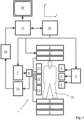
- a MR device 1 is shown as a block diagram.
- the device comprises superconducting or resistive main magnet coils 2 such that a substantially uniform, temporally constant main magnetic field B 0 is created along a z-axis through an examination volume.
- the device further comprises a set of (1 st , 2 nd , and - where applicable - 3 rd order) shimming coils 2', wherein the current flow through the individual shimming coils of the set 2' is controllable for the purpose of minimizing B 0 deviations within the examination volume.
- a magnetic resonance generation and manipulation system applies a series of RF pulses and switched magnetic field gradients to invert or excite nuclear magnetic spins, induce magnetic resonance, refocus magnetic resonance, manipulate magnetic resonance, spatially and otherwise encode the magnetic resonance, saturate spins, and the like to perform MR imaging.
- a gradient pulse amplifier 3 applies current pulses to selected ones of whole-body gradient coils 4, 5 and 6 along x, y and z-axes of the examination volume.
- a digital RF frequency transmitter 7 transmits RF pulses or pulse packets, via a send/receive switch 8, to a body RF coil 9 to transmit RF pulses into the examination volume.
- a typical MR imaging sequence is composed of a packet of RF pulse segments of short duration which, together with any applied magnetic field gradients, achieve a selected manipulation of nuclear magnetic resonance.
- the RF pulses are used to saturate resonance, excite resonance, invert magnetization, refocus resonance, or manipulate resonance and select a portion of a body 10 positioned in the examination volume.
- the MR signals are also picked up by the body RF coil 9.
- a set of local array RF coils 11, 12, 13 are placed contiguous to the region selected for imaging.
- the array coils 11, 12, 13 can be used to receive MR signals induced by body-coil RF transmissions.
- the resultant MR signals are picked up by the body RF coil 9 and/or by the array RF coils 11, 12, 13 and demodulated by a receiver 14 preferably including a preamplifier (not shown).
- the receiver 14 is connected to the RF coils 9, 11, 12 and 13 via the send/receive switch 8.
- a host computer 15 controls the shimming coils 2' as well as the gradient pulse amplifier 3 and the transmitter 7 to generate the imaging sequences of the invention.
- the receiver 14 receives a single or a plurality of MR data lines in rapid succession following each RF excitation pulse.
- a data acquisition system 16 performs analog-to-digital conversion of the received signals and converts each MR data line to a digital format suitable for further processing. In modem MR devices the data acquisition system 16 is a separate computer which is specialized in acquisition of raw image data.
- the digital raw image data are reconstructed into an image representation by a reconstruction processor 17 which applies a Fourier transform or other appropriate reconstruction algorithms, such as SENSE.
- the MR image may represent a planar slice through the patient, an array of parallel planar slices, a three-dimensional volume, or the like.
- the image is then stored in an image memory where it may be accessed for converting slices, projections, or other portions of the image representation into appropriate format for visualization, for example via a video monitor 18 which provides a man-readable display of the resultant MR image.
- Efficient TSE Dixon imaging can be achieved in an example outside the scope of the invention but useful for providing some context for the invention, by combining a unipolar single-echo readout at a low receive bandwidth with a bipolar dual-echo readout at a high bandwidth to maximize the SNR.
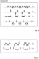
- FIG. 3 shows a pulse sequence diagram 31 of a TSE sequence constituting a first imaging sequence, in accordance with the example outside the scope of the invention but useful for providing some context for the invention.
- the diagram 31 shows switched magnetic field gradients in the frequency-encoding direction (M), the phase-encoding direction (P) and the slice-selection direction (S). Moreover, the diagram shows the RF excitation and refocusing pulses as well as the time intervals during which echo signals are acquired, designated by ACQ. A single echo signal is acquired during each interval ACQ at a first (low) receive bandwidth to obtain a high SNR. To this end, comparatively weak unipolar readout magnetic field gradients (in the M-direction) are chosen. A high sampling efficiency is reached in the first imaging sequence by sampling the MR signals during most of the interspacing between the refocusing pulses.
- Figure 3 shows a further pulse sequence diagram 32 for the second imaging sequence used for the example, which corresponds to the imaging sequence according to the invention.
- the second imaging sequence is also a TSE sequence with echo shifting to obtain a pair of echo signals in each time interval between two consecutive refocusing RF pulses.
- the pairs of echo signals are acquired using bipolar readout magnetic field gradients.
- Each pair of echo signals is acquired using a corresponding pair of readout magnetic field gradients having opposed polarities.
- the corresponding signal acquisition periods are indicated by ACQ1 and ACQ2.
- the first echo signal of each pair of echo signals is acquired during interval ACQ1 while the second echo signal of each pair of echo signals is acquired during interval ACQ2.
- the spacing between the refocusing RF pulses is essentially identical in the first and second imaging sequences, while the readout magnetic field gradient strength as well as the receiving signal bandwidth are doubled in the second imaging sequence with respect to the first imaging sequence to enable echo shifting.
- the first and second imaging sequences are used to acquire the single echo signals and the pairs of echo signals respectively.
- the timing of the bipolar readout gradients in the second imaging sequence (diagram 32) is chosen to shift the acquisition windows ACQ1, ACQ2 of the echo signals such that different phase offsets of the signal contributions from water protons and fat protons are provided on which the Dixon-type separation of these signal contributions is based in the final step of MR image reconstruction.
- three single-echo MR images can be reconstructed from the echo signals generated by the first and second imaging sequences.
- a three-point Dixon method can then directly be applied to the three single-echo MR images for separating the contributions from fat and water protons.
- the water and fat signal contributions can be estimated for each voxel by a least squares fitting approach (see Reeder et al., Magnetic Resonance in Medicine, 51, 35-45, 2004 ).
- the difference in SNR in the single-echo images is taken into account by using a correspondingly weighted linear least squares estimation instead, which provides a better SNR.
- the former can be reduced by shortening and strengthening the initial dephasing and the final rephasing lobes of the readout magnetic field gradients (while preserving their area).
- This is illustrated in the middle diagram of Figure 4 .
- the left diagram shows the readout magnetic field gradient lobes from diagram 32 of Figure 3 .
- the first moment can even be set to zero by strengthening the two middle lobes of the readout magnetic field gradient (possibly entailing the acquisition of partial echoes), as illustrated in the right diagram of Figure 4 .
- the first moment of the readout magnetic field gradient is then no longer zero at the time of the second echo signal.
- a phase encoding magnetic field gradient ('blip') can be introduced between the two acquisition intervals ACQ1, ACQ2, such that two different k-space lines are acquired in each interval between two consecutive refocusing RF pulses.
- the application of the blip magnetic field gradient leads to one half of the k-space lines being acquired with a negative shift of the echo signals and the other half of the k-space lines being acquired with a positive shift of the echo signals.
- These two subsets of k-space lines can simply be matched by exploiting their conjugate complex symmetry.
- a possible phase in the MR image is known from the echo signals generated with the first imaging sequence and can be considered appropriately in this process.
- the information gained on the FID artifacts by the bipolar dual-echo readout can be used to also suppress FID artifacts in the unipolar single-echo readout, without increasing scan time.
- a first water/fat separation can be performed without such a suppression.
- the FID contribution in this voxel known from the bipolar dual-echo readout can be modulated to reflect the phase evolution from the respective shift of the echo signals to the spin echo, using the information on the main magnetic field inhomogeneity provided by the first water/fat separation, and then subtracted from the corresponding signal in this voxel obtained from the unipolar single-echo readout.
- This can be limited to those voxels for which the FID contribution exceeds a certain threshold to limit potential loss of SNR.
- a second water/fat separation can be performed. It is also conceivable to perform a water/fat separation on the FID contribution only, in order to accurately predict the FID contribution to the signal obtained from the unipolar single-echo readout even for voxels containing a mixture of water and fat.
Landscapes
- Physics & Mathematics (AREA)
- High Energy & Nuclear Physics (AREA)
- Condensed Matter Physics & Semiconductors (AREA)
- General Physics & Mathematics (AREA)
- Health & Medical Sciences (AREA)
- General Health & Medical Sciences (AREA)
- Nuclear Medicine, Radiotherapy & Molecular Imaging (AREA)
- Radiology & Medical Imaging (AREA)
- Engineering & Computer Science (AREA)
- Signal Processing (AREA)
- Magnetic Resonance Imaging Apparatus (AREA)
Priority Applications (1)
| Application Number | Priority Date | Filing Date | Title |
|---|---|---|---|
| EP24190809.4A EP4446765A3 (en) | 2016-06-02 | 2017-06-01 | Dixon-type water-fat separation mr imaging |
Applications Claiming Priority (2)
| Application Number | Priority Date | Filing Date | Title |
|---|---|---|---|
| EP16172658 | 2016-06-02 | ||
| PCT/EP2017/063326 WO2017207700A1 (en) | 2016-06-02 | 2017-06-01 | Dixon-type water/fat separation mr imaging |
Related Child Applications (2)
| Application Number | Title | Priority Date | Filing Date |
|---|---|---|---|
| EP24190809.4A Division EP4446765A3 (en) | 2016-06-02 | 2017-06-01 | Dixon-type water-fat separation mr imaging |
| EP24190809.4A Division-Into EP4446765A3 (en) | 2016-06-02 | 2017-06-01 | Dixon-type water-fat separation mr imaging |
Publications (2)
| Publication Number | Publication Date |
|---|---|
| EP3465246A1 EP3465246A1 (en) | 2019-04-10 |
| EP3465246B1 true EP3465246B1 (en) | 2024-09-11 |
Family
ID=56098106
Family Applications (2)
| Application Number | Title | Priority Date | Filing Date |
|---|---|---|---|
| EP17727864.5A Active EP3465246B1 (en) | 2016-06-02 | 2017-06-01 | Dixon-type water/fat separation mr imaging |
| EP24190809.4A Withdrawn EP4446765A3 (en) | 2016-06-02 | 2017-06-01 | Dixon-type water-fat separation mr imaging |
Family Applications After (1)
| Application Number | Title | Priority Date | Filing Date |
|---|---|---|---|
| EP24190809.4A Withdrawn EP4446765A3 (en) | 2016-06-02 | 2017-06-01 | Dixon-type water-fat separation mr imaging |
Country Status (6)
| Country | Link |
|---|---|
| US (1) | US11041926B2 (enExample) |
| EP (2) | EP3465246B1 (enExample) |
| JP (2) | JP7208796B2 (enExample) |
| CN (1) | CN109219757B (enExample) |
| RU (1) | RU2739479C2 (enExample) |
| WO (1) | WO2017207700A1 (enExample) |
Families Citing this family (11)
| Publication number | Priority date | Publication date | Assignee | Title |
|---|---|---|---|---|
| RU2739479C2 (ru) * | 2016-06-02 | 2020-12-24 | Конинклейке Филипс Н.В. | Магнитно-резонансная томография с разделением воды и жира по методу диксона |
| JP2020522562A (ja) * | 2017-06-06 | 2020-07-30 | ストキューブ アンド シーオー., インコーポレイテッド | Btn1a1又はbtn1a1リガンドに結合する抗体及び分子を用いて癌を治療する方法 |
| DE102018200900B4 (de) | 2018-01-22 | 2023-02-02 | Siemens Healthcare Gmbh | Verfahren und Magnetresonanzanlage zur Artefaktvermeidung bei schnellen 3D Spinechosequenzen |
| EP3531154A1 (en) * | 2018-02-22 | 2019-08-28 | Koninklijke Philips N.V. | Dixon mr imaging using a multi-gradient-echo sequence |
| EP3715896B1 (en) * | 2019-03-27 | 2023-02-15 | Siemens Healthcare GmbH | Minimization of signal losses in multi-echo imaging |
| EP3792647A1 (en) * | 2019-09-16 | 2021-03-17 | Koninklijke Philips N.V. | Dixon-type water/fat separation mr imaging |
| EP4012434A1 (en) * | 2020-12-08 | 2022-06-15 | Koninklijke Philips N.V. | Dixon-type water/fat separation mr imaging |
| CN114820403B (zh) | 2021-01-27 | 2025-04-29 | 西门子(深圳)磁共振有限公司 | 磁共振水脂图像分离方法、装置、成像系统及存储介质 |
| EP4043902A1 (en) * | 2021-02-11 | 2022-08-17 | Koninklijke Philips N.V. | Dixon-type water/fat separation mr imaging |
| CN115144801B (zh) * | 2021-03-30 | 2025-08-19 | 西门子(深圳)磁共振有限公司 | 飞跃时间成像方法、装置及磁共振成像系统 |
| EP4653904A1 (en) * | 2024-05-21 | 2025-11-26 | Koninklijke Philips N.V. | Removal of free induction decay artifacts in turbo spin echo mri images |
Family Cites Families (38)
| Publication number | Priority date | Publication date | Assignee | Title |
|---|---|---|---|---|
| US6263228B1 (en) | 1998-08-27 | 2001-07-17 | Toshiba America, Mri, Inc. | Method and apparatus for providing separate water-dominant and fat-dominant images from single scan single point dixon MRI sequences |
| US6801800B2 (en) * | 1999-11-29 | 2004-10-05 | Kabushiki Kaisha Toshiba | MR imaging using ECG-prep scan |
| US20040043022A1 (en) | 2001-04-30 | 2004-03-04 | Heuer Josef Georg | Treating t-cell mediated diseases by modulating dr6 activity |
| US7027853B2 (en) | 2002-09-26 | 2006-04-11 | Board Of Regents, The University Of Texas System | Data acquisition method and apparatus for MR imaging |
| DK2381382T3 (en) * | 2003-10-14 | 2018-03-05 | Verseon | Method and apparatus for analyzing molecular configurations and combinations |
| RU2270995C1 (ru) * | 2004-07-05 | 2006-02-27 | Кубанский государственный технологический университет | Способ определения содержания влаги в мучном кондитерском изделии |
| WO2006121827A2 (en) | 2005-05-06 | 2006-11-16 | Board Of Regents, The University Of Texas System | System, program product, and method of acquiring and processing mri data for simultaneous determination of water, fat, and transverse relaxation time constants |
| RU2308709C1 (ru) * | 2006-02-26 | 2007-10-20 | Государственное образовательное учреждение высшего профессионального образования "Кубанский государственный технологический университет" (ГОУВПО "КубГТУ") | Способ определения содержания жира в маргарине |
| US7535222B2 (en) * | 2007-01-02 | 2009-05-19 | The Board Of Trustees Of The Leland Stanford Junior University | MRI data acquisition using propeller k-space data acquisition |
| EP2239592A1 (en) | 2009-04-08 | 2010-10-13 | Universitätsklinikum Freiburg | Simultaneous excitation and acquisition of signal from multiple slices in the RARE sequence (multiplex RARE) |
| WO2011098941A1 (en) | 2010-02-09 | 2011-08-18 | Koninklijke Philips Electronics N.V. | Coronary magnetic resonance angiography with signal separation for water and fat |
| CN102232831B (zh) * | 2010-04-30 | 2016-03-30 | 西门子(深圳)磁共振有限公司 | 一种实现水脂分离的磁共振成像方法 |
| CN102232830B (zh) * | 2010-04-30 | 2014-09-03 | 西门子(深圳)磁共振有限公司 | 一种磁共振成像水脂分离方法 |
| WO2011161566A1 (en) | 2010-06-24 | 2011-12-29 | Koninklijke Philips Electronics N.V. | Dynamic contrast enhanced mr imaging with compressed sensing reconstruction |
| WO2012061839A2 (en) * | 2010-11-05 | 2012-05-10 | The Regents Of The University Of California | Mri-based fat double bond mapping |
| WO2012073181A2 (en) * | 2010-12-02 | 2012-06-07 | Koninklijke Philips Electronics N.V. | Mr imaging using a multi-point dixon technique |
| EP2508910B1 (en) * | 2011-03-22 | 2020-08-19 | Toshiba Medical Systems Corporation | Magnetic resonance imaging system and process |
| CN102736047B (zh) * | 2011-04-13 | 2016-04-13 | 深圳迈瑞生物医疗电子股份有限公司 | 磁共振系统及其水脂分离成像方法、装置 |
| EP2515136A1 (en) * | 2011-04-21 | 2012-10-24 | Koninklijke Philips Electronics N.V. | Contrast enhanced magnetic resonance angiography with chemical shift encoding for fat suppression |
| SG10201602141QA (en) * | 2011-09-25 | 2016-04-28 | Theranos Inc | Systems And Methods For Multi-Analysis |
| RU2605524C2 (ru) | 2011-12-23 | 2016-12-20 | Конинклейке Филипс Н.В. | Магнитно-резонансная визуализация с подавлением артефактов потока |
| EP2610632A1 (en) * | 2011-12-29 | 2013-07-03 | Koninklijke Philips Electronics N.V. | MRI with Dixon-type water/fat separation and prior knowledge about inhomogeneity of the main magnetic field |
| EP2626718A1 (en) * | 2012-02-09 | 2013-08-14 | Koninklijke Philips Electronics N.V. | MRI with motion correction using navigators acquired using a Dixon technique |
| US8824766B2 (en) * | 2012-02-10 | 2014-09-02 | Duke University | Systems and methods for automated magnetic resonance imaging |
| CN103257333B (zh) * | 2012-02-17 | 2016-04-13 | 西门子(深圳)磁共振有限公司 | 一种磁共振成像中的水脂分离成像方法及装置 |
| WO2013130587A1 (en) | 2012-02-28 | 2013-09-06 | The Board Of Regents Of The University Of Texas System | Method and apparatus for extended phase correction in phase sensitive magnetic resonance imaging |
| US20130300410A1 (en) * | 2012-03-30 | 2013-11-14 | Max-Delbrueck- Centrum Fuer Molekulare Medizine | Method for fast spin-echo MRT imaging |
| US20130314088A1 (en) * | 2012-04-19 | 2013-11-28 | New York University | Multi-channel coil arrangement |
| CN103505210B (zh) | 2012-06-28 | 2015-09-16 | 西门子(深圳)磁共振有限公司 | 一种实现水脂分离的磁共振成像方法和装置 |
| DE102013201616B3 (de) * | 2013-01-31 | 2014-07-17 | Siemens Aktiengesellschaft | TSE-basierte, gegen lokale B0-Feldvariationen unempfindliche MR-Mulitschicht-Anregung |
| JP2016512780A (ja) * | 2013-03-21 | 2016-05-09 | コーニンクレッカ フィリップス エヌ ヴェKoninklijke Philips N.V. | 圧縮センシングを使用したmr画像の再構成 |
| DE102013205208B4 (de) * | 2013-03-25 | 2015-02-12 | Siemens Aktiengesellschaft | Multiecho-Magnetresonanz-Messsequenz mit erhöhter Auflösung |
| US10274566B2 (en) | 2013-04-03 | 2019-04-30 | Koninklijke Philips N.V. | Dixon-type water/fat separation MRI using high-SNR in-phase image and lower-SNR at least partially out-of-phase image |
| WO2014203253A1 (en) | 2013-06-19 | 2014-12-24 | Yeda Research And Development Co. Ltd. | Methods for spatial and spectral selectivity in magnetic resonance imaging and spectroscopy |
| US10234522B2 (en) | 2013-09-16 | 2019-03-19 | Koninklijke Philips N.V. | MR imaging with dixon-type water/fat separation |
| CN105433944B (zh) * | 2014-07-31 | 2018-07-03 | 西门子公司 | 用于获取对象的磁共振数据的方法及装置 |
| CN104382597A (zh) * | 2014-11-11 | 2015-03-04 | 奥泰医疗系统有限责任公司 | 一种磁共振成像中的Dixon水脂分离及辨析方法及系统 |
| RU2739479C2 (ru) * | 2016-06-02 | 2020-12-24 | Конинклейке Филипс Н.В. | Магнитно-резонансная томография с разделением воды и жира по методу диксона |
-
2017
- 2017-06-01 RU RU2018146906A patent/RU2739479C2/ru active
- 2017-06-01 US US16/305,089 patent/US11041926B2/en active Active
- 2017-06-01 EP EP17727864.5A patent/EP3465246B1/en active Active
- 2017-06-01 JP JP2018562622A patent/JP7208796B2/ja active Active
- 2017-06-01 EP EP24190809.4A patent/EP4446765A3/en not_active Withdrawn
- 2017-06-01 CN CN201780033701.7A patent/CN109219757B/zh active Active
- 2017-06-01 WO PCT/EP2017/063326 patent/WO2017207700A1/en not_active Ceased
-
2022
- 2022-08-09 JP JP2022126773A patent/JP2022169618A/ja active Pending
Also Published As
| Publication number | Publication date |
|---|---|
| EP3465246A1 (en) | 2019-04-10 |
| JP7208796B2 (ja) | 2023-01-19 |
| CN109219757B (zh) | 2021-10-12 |
| EP4446765A2 (en) | 2024-10-16 |
| RU2018146906A3 (enExample) | 2020-07-09 |
| RU2018146906A (ru) | 2020-07-09 |
| JP2022169618A (ja) | 2022-11-09 |
| CN109219757A (zh) | 2019-01-15 |
| RU2739479C2 (ru) | 2020-12-24 |
| EP4446765A3 (en) | 2025-01-15 |
| US20200319280A1 (en) | 2020-10-08 |
| US11041926B2 (en) | 2021-06-22 |
| JP2019522513A (ja) | 2019-08-15 |
| WO2017207700A1 (en) | 2017-12-07 |
Similar Documents
| Publication | Publication Date | Title |
|---|---|---|
| EP3465246B1 (en) | Dixon-type water/fat separation mr imaging | |
| US10274566B2 (en) | Dixon-type water/fat separation MRI using high-SNR in-phase image and lower-SNR at least partially out-of-phase image | |
| EP2798364B1 (en) | Mr imaging with suppression of flow artefacts | |
| JP7583858B2 (ja) | 並列マルチスライスmr撮像 | |
| EP3673281B1 (en) | Dixon-type water/fat separation mr imaging | |
| EP3635426B1 (en) | Dual-echo dixon-type water/fat separation mr imaging | |
| US10859652B2 (en) | MR imaging with dixon-type water/fat separation | |
| US10895619B2 (en) | MR imaging with Dixon-type water/fat separation | |
| WO2018114554A1 (en) | Dixon-type water/fat separation mr imaging | |
| US12392851B2 (en) | Dixon-type water/fat separation MR imaging | |
| US11226385B2 (en) | Dixon type water/fat separation MR imaging with improved fat shift correction | |
| EP3792647A1 (en) | Dixon-type water/fat separation mr imaging |
Legal Events
| Date | Code | Title | Description |
|---|---|---|---|
| STAA | Information on the status of an ep patent application or granted ep patent |
Free format text: STATUS: UNKNOWN |
|
| STAA | Information on the status of an ep patent application or granted ep patent |
Free format text: STATUS: THE INTERNATIONAL PUBLICATION HAS BEEN MADE |
|
| PUAI | Public reference made under article 153(3) epc to a published international application that has entered the european phase |
Free format text: ORIGINAL CODE: 0009012 |
|
| STAA | Information on the status of an ep patent application or granted ep patent |
Free format text: STATUS: REQUEST FOR EXAMINATION WAS MADE |
|
| 17P | Request for examination filed |
Effective date: 20190102 |
|
| AK | Designated contracting states |
Kind code of ref document: A1 Designated state(s): AL AT BE BG CH CY CZ DE DK EE ES FI FR GB GR HR HU IE IS IT LI LT LU LV MC MK MT NL NO PL PT RO RS SE SI SK SM TR |
|
| AX | Request for extension of the european patent |
Extension state: BA ME |
|
| DAV | Request for validation of the european patent (deleted) | ||
| DAX | Request for extension of the european patent (deleted) | ||
| RAP1 | Party data changed (applicant data changed or rights of an application transferred) |
Owner name: KONINKLIJKE PHILIPS N.V. |
|
| STAA | Information on the status of an ep patent application or granted ep patent |
Free format text: STATUS: EXAMINATION IS IN PROGRESS |
|
| 17Q | First examination report despatched |
Effective date: 20210805 |
|
| GRAP | Despatch of communication of intention to grant a patent |
Free format text: ORIGINAL CODE: EPIDOSNIGR1 |
|
| STAA | Information on the status of an ep patent application or granted ep patent |
Free format text: STATUS: GRANT OF PATENT IS INTENDED |
|
| INTG | Intention to grant announced |
Effective date: 20240506 |
|
| GRAS | Grant fee paid |
Free format text: ORIGINAL CODE: EPIDOSNIGR3 |
|
| GRAA | (expected) grant |
Free format text: ORIGINAL CODE: 0009210 |
|
| STAA | Information on the status of an ep patent application or granted ep patent |
Free format text: STATUS: THE PATENT HAS BEEN GRANTED |
|
| AK | Designated contracting states |
Kind code of ref document: B1 Designated state(s): AL AT BE BG CH CY CZ DE DK EE ES FI FR GB GR HR HU IE IS IT LI LT LU LV MC MK MT NL NO PL PT RO RS SE SI SK SM TR |
|
| REG | Reference to a national code |
Ref country code: GB Ref legal event code: FG4D |
|
| REG | Reference to a national code |
Ref country code: CH Ref legal event code: EP |
|
| REG | Reference to a national code |
Ref country code: DE Ref legal event code: R096 Ref document number: 602017084783 Country of ref document: DE |
|
| REG | Reference to a national code |
Ref country code: IE Ref legal event code: FG4D |
|
| REG | Reference to a national code |
Ref country code: DE Ref legal event code: R084 Ref document number: 602017084783 Country of ref document: DE |
|
| REG | Reference to a national code |
Ref country code: LT Ref legal event code: MG9D |
|
| PG25 | Lapsed in a contracting state [announced via postgrant information from national office to epo] |
Ref country code: NO Free format text: LAPSE BECAUSE OF FAILURE TO SUBMIT A TRANSLATION OF THE DESCRIPTION OR TO PAY THE FEE WITHIN THE PRESCRIBED TIME-LIMIT Effective date: 20241211 |
|
| REG | Reference to a national code |
Ref country code: NL Ref legal event code: MP Effective date: 20240911 |
|
| PG25 | Lapsed in a contracting state [announced via postgrant information from national office to epo] |
Ref country code: GR Free format text: LAPSE BECAUSE OF FAILURE TO SUBMIT A TRANSLATION OF THE DESCRIPTION OR TO PAY THE FEE WITHIN THE PRESCRIBED TIME-LIMIT Effective date: 20241212 Ref country code: FI Free format text: LAPSE BECAUSE OF FAILURE TO SUBMIT A TRANSLATION OF THE DESCRIPTION OR TO PAY THE FEE WITHIN THE PRESCRIBED TIME-LIMIT Effective date: 20240911 |
|
| PG25 | Lapsed in a contracting state [announced via postgrant information from national office to epo] |
Ref country code: BG Free format text: LAPSE BECAUSE OF FAILURE TO SUBMIT A TRANSLATION OF THE DESCRIPTION OR TO PAY THE FEE WITHIN THE PRESCRIBED TIME-LIMIT Effective date: 20240911 |
|
| PG25 | Lapsed in a contracting state [announced via postgrant information from national office to epo] |
Ref country code: LV Free format text: LAPSE BECAUSE OF FAILURE TO SUBMIT A TRANSLATION OF THE DESCRIPTION OR TO PAY THE FEE WITHIN THE PRESCRIBED TIME-LIMIT Effective date: 20240911 |
|
| PG25 | Lapsed in a contracting state [announced via postgrant information from national office to epo] |
Ref country code: HR Free format text: LAPSE BECAUSE OF FAILURE TO SUBMIT A TRANSLATION OF THE DESCRIPTION OR TO PAY THE FEE WITHIN THE PRESCRIBED TIME-LIMIT Effective date: 20240911 |
|
| PG25 | Lapsed in a contracting state [announced via postgrant information from national office to epo] |
Ref country code: ES Free format text: LAPSE BECAUSE OF FAILURE TO SUBMIT A TRANSLATION OF THE DESCRIPTION OR TO PAY THE FEE WITHIN THE PRESCRIBED TIME-LIMIT Effective date: 20240911 |
|
| PG25 | Lapsed in a contracting state [announced via postgrant information from national office to epo] |
Ref country code: NO Free format text: LAPSE BECAUSE OF FAILURE TO SUBMIT A TRANSLATION OF THE DESCRIPTION OR TO PAY THE FEE WITHIN THE PRESCRIBED TIME-LIMIT Effective date: 20241211 Ref country code: LV Free format text: LAPSE BECAUSE OF FAILURE TO SUBMIT A TRANSLATION OF THE DESCRIPTION OR TO PAY THE FEE WITHIN THE PRESCRIBED TIME-LIMIT Effective date: 20240911 Ref country code: HR Free format text: LAPSE BECAUSE OF FAILURE TO SUBMIT A TRANSLATION OF THE DESCRIPTION OR TO PAY THE FEE WITHIN THE PRESCRIBED TIME-LIMIT Effective date: 20240911 Ref country code: GR Free format text: LAPSE BECAUSE OF FAILURE TO SUBMIT A TRANSLATION OF THE DESCRIPTION OR TO PAY THE FEE WITHIN THE PRESCRIBED TIME-LIMIT Effective date: 20241212 Ref country code: FI Free format text: LAPSE BECAUSE OF FAILURE TO SUBMIT A TRANSLATION OF THE DESCRIPTION OR TO PAY THE FEE WITHIN THE PRESCRIBED TIME-LIMIT Effective date: 20240911 Ref country code: ES Free format text: LAPSE BECAUSE OF FAILURE TO SUBMIT A TRANSLATION OF THE DESCRIPTION OR TO PAY THE FEE WITHIN THE PRESCRIBED TIME-LIMIT Effective date: 20240911 Ref country code: BG Free format text: LAPSE BECAUSE OF FAILURE TO SUBMIT A TRANSLATION OF THE DESCRIPTION OR TO PAY THE FEE WITHIN THE PRESCRIBED TIME-LIMIT Effective date: 20240911 |
|
| REG | Reference to a national code |
Ref country code: AT Ref legal event code: MK05 Ref document number: 1723166 Country of ref document: AT Kind code of ref document: T Effective date: 20240911 |
|
| PG25 | Lapsed in a contracting state [announced via postgrant information from national office to epo] |
Ref country code: NL Free format text: LAPSE BECAUSE OF FAILURE TO SUBMIT A TRANSLATION OF THE DESCRIPTION OR TO PAY THE FEE WITHIN THE PRESCRIBED TIME-LIMIT Effective date: 20240911 |
|
| PG25 | Lapsed in a contracting state [announced via postgrant information from national office to epo] |
Ref country code: PT Free format text: LAPSE BECAUSE OF FAILURE TO SUBMIT A TRANSLATION OF THE DESCRIPTION OR TO PAY THE FEE WITHIN THE PRESCRIBED TIME-LIMIT Effective date: 20250113 Ref country code: IS Free format text: LAPSE BECAUSE OF FAILURE TO SUBMIT A TRANSLATION OF THE DESCRIPTION OR TO PAY THE FEE WITHIN THE PRESCRIBED TIME-LIMIT Effective date: 20250111 |
|
| PG25 | Lapsed in a contracting state [announced via postgrant information from national office to epo] |
Ref country code: RO Free format text: LAPSE BECAUSE OF FAILURE TO SUBMIT A TRANSLATION OF THE DESCRIPTION OR TO PAY THE FEE WITHIN THE PRESCRIBED TIME-LIMIT Effective date: 20240911 Ref country code: SM Free format text: LAPSE BECAUSE OF FAILURE TO SUBMIT A TRANSLATION OF THE DESCRIPTION OR TO PAY THE FEE WITHIN THE PRESCRIBED TIME-LIMIT Effective date: 20240911 |
|
| PG25 | Lapsed in a contracting state [announced via postgrant information from national office to epo] |
Ref country code: EE Free format text: LAPSE BECAUSE OF FAILURE TO SUBMIT A TRANSLATION OF THE DESCRIPTION OR TO PAY THE FEE WITHIN THE PRESCRIBED TIME-LIMIT Effective date: 20240911 Ref country code: AT Free format text: LAPSE BECAUSE OF FAILURE TO SUBMIT A TRANSLATION OF THE DESCRIPTION OR TO PAY THE FEE WITHIN THE PRESCRIBED TIME-LIMIT Effective date: 20240911 |
|
| PG25 | Lapsed in a contracting state [announced via postgrant information from national office to epo] |
Ref country code: PL Free format text: LAPSE BECAUSE OF FAILURE TO SUBMIT A TRANSLATION OF THE DESCRIPTION OR TO PAY THE FEE WITHIN THE PRESCRIBED TIME-LIMIT Effective date: 20240911 Ref country code: CZ Free format text: LAPSE BECAUSE OF FAILURE TO SUBMIT A TRANSLATION OF THE DESCRIPTION OR TO PAY THE FEE WITHIN THE PRESCRIBED TIME-LIMIT Effective date: 20240911 |
|
| PG25 | Lapsed in a contracting state [announced via postgrant information from national office to epo] |
Ref country code: IT Free format text: LAPSE BECAUSE OF FAILURE TO SUBMIT A TRANSLATION OF THE DESCRIPTION OR TO PAY THE FEE WITHIN THE PRESCRIBED TIME-LIMIT Effective date: 20240911 Ref country code: SK Free format text: LAPSE BECAUSE OF FAILURE TO SUBMIT A TRANSLATION OF THE DESCRIPTION OR TO PAY THE FEE WITHIN THE PRESCRIBED TIME-LIMIT Effective date: 20240911 |
|
| REG | Reference to a national code |
Ref country code: DE Ref legal event code: R097 Ref document number: 602017084783 Country of ref document: DE |
|
| PGFP | Annual fee paid to national office [announced via postgrant information from national office to epo] |
Ref country code: DE Payment date: 20250626 Year of fee payment: 9 |
|
| PG25 | Lapsed in a contracting state [announced via postgrant information from national office to epo] |
Ref country code: DK Free format text: LAPSE BECAUSE OF FAILURE TO SUBMIT A TRANSLATION OF THE DESCRIPTION OR TO PAY THE FEE WITHIN THE PRESCRIBED TIME-LIMIT Effective date: 20240911 |
|
| PGFP | Annual fee paid to national office [announced via postgrant information from national office to epo] |
Ref country code: GB Payment date: 20250617 Year of fee payment: 9 |
|
| PLBE | No opposition filed within time limit |
Free format text: ORIGINAL CODE: 0009261 |
|
| STAA | Information on the status of an ep patent application or granted ep patent |
Free format text: STATUS: NO OPPOSITION FILED WITHIN TIME LIMIT |
|
| 26N | No opposition filed |
Effective date: 20250612 |
|
| PG25 | Lapsed in a contracting state [announced via postgrant information from national office to epo] |
Ref country code: SE Free format text: LAPSE BECAUSE OF FAILURE TO SUBMIT A TRANSLATION OF THE DESCRIPTION OR TO PAY THE FEE WITHIN THE PRESCRIBED TIME-LIMIT Effective date: 20240911 |