EP3465155B1 - Système d'inspection de surface et procédé d'inspection de surface - Google Patents
Système d'inspection de surface et procédé d'inspection de surface Download PDFInfo
- Publication number
- EP3465155B1 EP3465155B1 EP17732308.6A EP17732308A EP3465155B1 EP 3465155 B1 EP3465155 B1 EP 3465155B1 EP 17732308 A EP17732308 A EP 17732308A EP 3465155 B1 EP3465155 B1 EP 3465155B1
- Authority
- EP
- European Patent Office
- Prior art keywords
- camera
- bright
- sheet element
- dark
- line
- Prior art date
- Legal status (The legal status is an assumption and is not a legal conclusion. Google has not performed a legal analysis and makes no representation as to the accuracy of the status listed.)
- Active
Links
- 238000007689 inspection Methods 0.000 title claims description 25
- 238000000034 method Methods 0.000 title claims description 14
- 238000005286 illumination Methods 0.000 claims description 26
- 238000011156 evaluation Methods 0.000 claims description 13
- 230000003287 optical effect Effects 0.000 claims description 9
- 239000011888 foil Substances 0.000 description 10
- 238000003908 quality control method Methods 0.000 description 6
- 239000002966 varnish Substances 0.000 description 4
- 239000011111 cardboard Substances 0.000 description 3
- 239000000123 paper Substances 0.000 description 3
- 238000004026 adhesive bonding Methods 0.000 description 2
- 238000010030 laminating Methods 0.000 description 2
- 239000000463 material Substances 0.000 description 2
- 239000004033 plastic Substances 0.000 description 2
- 239000011248 coating agent Substances 0.000 description 1
- 238000000576 coating method Methods 0.000 description 1
- -1 holograms Substances 0.000 description 1
- 239000011087 paperboard Substances 0.000 description 1
Images


Classifications
-
- G—PHYSICS
- G01—MEASURING; TESTING
- G01N—INVESTIGATING OR ANALYSING MATERIALS BY DETERMINING THEIR CHEMICAL OR PHYSICAL PROPERTIES
- G01N21/00—Investigating or analysing materials by the use of optical means, i.e. using sub-millimetre waves, infrared, visible or ultraviolet light
- G01N21/17—Systems in which incident light is modified in accordance with the properties of the material investigated
- G01N21/55—Specular reflectivity
- G01N21/57—Measuring gloss
-
- G—PHYSICS
- G01—MEASURING; TESTING
- G01N—INVESTIGATING OR ANALYSING MATERIALS BY DETERMINING THEIR CHEMICAL OR PHYSICAL PROPERTIES
- G01N21/00—Investigating or analysing materials by the use of optical means, i.e. using sub-millimetre waves, infrared, visible or ultraviolet light
- G01N21/84—Systems specially adapted for particular applications
- G01N21/88—Investigating the presence of flaws or contamination
- G01N21/89—Investigating the presence of flaws or contamination in moving material, e.g. running paper or textiles
- G01N21/8901—Optical details; Scanning details
-
- G—PHYSICS
- G01—MEASURING; TESTING
- G01N—INVESTIGATING OR ANALYSING MATERIALS BY DETERMINING THEIR CHEMICAL OR PHYSICAL PROPERTIES
- G01N21/00—Investigating or analysing materials by the use of optical means, i.e. using sub-millimetre waves, infrared, visible or ultraviolet light
- G01N21/84—Systems specially adapted for particular applications
- G01N21/86—Investigating moving sheets
-
- G—PHYSICS
- G01—MEASURING; TESTING
- G01N—INVESTIGATING OR ANALYSING MATERIALS BY DETERMINING THEIR CHEMICAL OR PHYSICAL PROPERTIES
- G01N21/00—Investigating or analysing materials by the use of optical means, i.e. using sub-millimetre waves, infrared, visible or ultraviolet light
- G01N21/84—Systems specially adapted for particular applications
- G01N21/88—Investigating the presence of flaws or contamination
- G01N21/8806—Specially adapted optical and illumination features
- G01N2021/8822—Dark field detection
- G01N2021/8825—Separate detection of dark field and bright field
-
- G—PHYSICS
- G01—MEASURING; TESTING
- G01N—INVESTIGATING OR ANALYSING MATERIALS BY DETERMINING THEIR CHEMICAL OR PHYSICAL PROPERTIES
- G01N2201/00—Features of devices classified in G01N21/00
- G01N2201/06—Illumination; Optics
- G01N2201/062—LED's
Definitions
- the invention relates to a surface inspection system for inspecting the surface of sheet elements present in an inspection area.
- the invention further relates to a method of identifying highly reflective surface areas on a sheet element being moved through a sheet element processing machine.
- the invention can in particular be implemented in a quality control station in a sheet element processing machine.
- sheet element processing machine is here intended to comprise any machine which is being used for processing sheet elements such as paper, cardboard, plastic foil or similar materials, in particular printing machines, coating machines, laminating machines and converting machines (for example cutting, stamping, folding and/or gluing machines).
- EP 2 397 840 A2 provides an image forming apparatus whereby data based on light including specular reflected light and diffuse reflected light can be accurately separated into data based solely on specular reflected light and data based solely on diffuse reflected light.
- the invention provides a surface inspection system suitable for determining the position of glossy portions on the surface of sheet elements present in an inspection area, comprising an image evaluation unit, a camera, a dark-field illuminator and a bright-field illuminator, the image evaluation unit being configured to subtract a line image captured under bright-field illumination conditions from a line image captured under dark-field illumination conditions.
- the intensity of the light originating from the dark-field illuminator is, at the camera, the same as the intensity of the light originating from the bright-field illuminator when a sheet element is being inspected which has a diffusely reflecting surface.
- This object is also achieved with a method of identifying reflective surface areas on a sheet element being moved through a sheet element processing machine, in particular by using the system as defined above, wherein first a line image of the surface of the sheet element in the viewing area is being captured under bright-field illumination conditions and a line image of the same surface of the sheet element in the viewing area is being captured under dark-field illumination conditions, and wherein then the two line images are compared by being subtracted from each other, wherein the surface is identified as being reflective if the difference between the two line images is above a predefined threshold.
- the power of the dark-field illuminator and of the bright-field illuminator is set or controlled such that the intensity of the light reflected to the camera from a diffusely reflecting surface of sheet element is the same for both illuminators.
- the invention is based on the general concept of taking advantage of the difference in reflection which can be observed when illuminating diffusely reflecting surfaces like a Lambertian diffuser (e.g. white paper) on the one hand and glossy surfaces (e.g. a foil, a hologram or varnish) on the other hand.
- a Lambertian diffuser e.g. white paper
- glossy surfaces e.g. a foil, a hologram or varnish
- the intensity of the line image captured by the camera is (almost) identical.
- the intensity, seen by the camera, of the light originating from the bright-field illuminator is much higher than the intensity of the light originating from the dark-field illuminator. This difference can be detected relatively easily even at a sheet element being moved with high speeds.
- the camera can be a 2D camera (area camera). In view of the amount of data to be processed, it however is preferred to use a line camera.
- the term "line image" is in the following being used when referring to the images captured by the camera. If the camera however is an area camera, the line image captured by the camera does not consist of a single line only but of a plurality of lines.
- the dark-field illuminator comprises a single row of LEDs along which two oppositely arranged reflectors are provided.
- the dark-field illuminator provides a light which is far from specular to prevent that any steep reflective area appears bright when illuminated by the dark-field illuminator.
- the bright-field illuminator preferably comprises a plurality of rows of LEDs which are arranged in parallel.
- the different rows are arranged with different optical planes so that there will always be some light which is being directly reflected, under close-to-specular reflection conditions, towards the camera even if the surface of the sheet element in the viewing area is not perfectly plane.
- bright-field conditions are maintained even for steep areas on the sheet element.
- the line image captured under bright-field illumination can be very easily compared with the line image captured under dark-field illumination because the intensity of the light originating from the dark-field illuminator is, at the camera, the same as the intensity of the light originating from the bright-field illuminator when a sheet element is being inspected which has a diffusely reflecting surface. As the comparison is made by subtracting the line images from each other, the result is zero for surface portions which are not reflective.
- the optical plane of the dark-field illuminator is arranged at an angle of approx 45° with respect to a plane which is perpendicular to the orientation of the viewing area
- the optical plane of the bright-field illuminator is arranged at an angle of approx 30° with respect to a plane which is perpendicular to the orientation of the viewing area
- the viewing plane of the camera is arranged at an angle of approx. 20° with respect to a plane which is perpendicular to the orientation of the viewing area.
- the camera has a resolution, at the surface of the sheet element to be inspected, in the range of 0.05 to 0.6 mm and preferably of the order of 0.1 mm. A higher resolution is generally possible but results in more data having to be analyzed.
- the images can be compared line by line and pixel by pixel so as to obtain precise information on the position of glossy surfaces both in the x direction and the y direction.
- a reconstructed image is being created based on the line images captured under dark-field illumination, and a reconstructed image is being created based on the line images captured under bright-field illumination conditions, wherein reflective surfaces are being identified by comparing the reconstructed images.
- This comparison can be made either for the entire reconstructed images or for selected parts only.
- the sheet element is being moved with respect to the surface inspection system with a speed in the order 1 to 15 m/s.
- the camera is adapted for capturing more than 10,000 line images/s and preferably more than 40,000 line images/s.
- a quality control station 2 is schematically shown, which is employed in a sheet element processing machine of which conveyor tables 3 can be seen.
- the sheet element processing machine can process sheet elements 4 which are being transported in the direction of arrow A.
- the sheet elements 4 can be sheets of paper, cardboard, plastic foil or a similar material, or they can be in the form of a longer web.
- the sheet element processing machine can be a printing machine, a stamping machine, a laminating machine, a folding machine, a gluing machine, etc.
- the quality control station 2 is used for controlling the quality of the sheet elements 4. According to the invention, the quality control station 2 is used for determining the position of "glossy portions" on the surface of the sheet elements 4. "Glossy portions” are portions with a highly reflective surface. Examples for such glossy portions are holograms, foil and/or varnish present on the sheet element 4.
- the quality control station comprises a surface inspection system 10.
- the surface inspection system 10 comprises a camera 12, a dark-field illuminator 14, a bright-field illuminator 16 and an image evaluation unit 18.
- Camera 12 is adapted for capturing a line image of a viewing area (a line of interest) 20 which extends perpendicularly to the direction A over the entire width of the sheet element processing machine. It is arranged at an angle of approx. 20° with respect to a median plane M which is perpendicular to the surface of the sheet elements 4 within the viewing area.
- Dark-field illuminator 14 is adapted for illuminating the viewing area 20.
- the optical plane of the dark-field illuminator 14 is arranged at an angle of approx. 45° with respect to median plane.
- Dark-field illuminator 14 can generally be of any type. In a particular embodiment, it comprises a row of LEDs arranged adjacent each other, and two reflectors arranged opposite each other along the row of LEDs. This type of illuminator can be used for illuminating the surface of the sheet elements 4 in the viewing area 20 with an intensity which is constant despite variations in height.
- Bright-field illuminator 16 is also adapted for illuminating the viewing area 20.
- the optical plane of the bright-field illuminator 16 is arranged at an angle of approx. 30° with respect to the median plane.
- Bright-field illuminator 16 can generally be of any type. In a particular embodiment, it comprises several parallel rows of LEDs arranged adjacent each other, with each row being adapted for illuminating viewing area 20. This type of illuminator can be used in different applications for directing light in different directions to viewing area 20.
- a diffuser can be used for ensuring an even radiance when seen from viewing area 20 in order to have an even bright-field illuminator.
- illuminator 14 In view of the fact that illuminator 14 is being used as a dark-field illuminator, it is arranged on the same side of median plane M as camera 12. Illuminator 16 however is, since it is being used as a bright-field illuminator, arranged on the opposite side of median plane M. Depending on the particular circumstances, it is possible to use only one of the different rows of LEDs, namely the one which has its optical plane inclined with respect to median plane M by an angle close to 20°. In other words, it is the row of LEDs which camera 12 could see under specular reflection conditions on the surface of sheet element 4. As an alternative, several rows of LEDs of bright-field illuminator 16 are being used, with the optical plane of some of the rows being inclined at angles which are different from the angle at which camera 12 is arranged with respect to median plane M.
- the power of the dark-field illuminator 14 and of the bright-field illuminator 16 is set or controlled such that the intensity of the light reflected to camera 12 from a diffusely reflecting surface of sheet element 4 is the same for both illuminators.
- the intensity of light originating from bright-field illuminator 16, reflected on a diffusely reflecting surface of sheet element 4 in viewing area 20 and then received by camera 12 is the same as the intensity of reflected light originating from dark-field illuminator 14, reflected on the same diffusely reflecting surface of sheet element 4 in viewing area 20 and then received by camera 12.
- the diffusely reflecting surface can be paper or cardboard.
- both illuminators 14, 16 are activated one after the other, and camera 12 captures a line image for each illumination situation. These line images are evaluated by image evaluation unit 18 where they are subtracted from each other.
- FIG. 4 schematically shows in the upper half line images which are being captured by camera 12.
- each line image is shown to be twelve pixels wide.
- a line image covering the entire width of the viewing area 20 will consist of several thousands to several ten thousands of pixels as camera 12 usually has a resolution, in the viewing area at the level of the surface of the sheet elements, of the order of 0.05 mm to 0.3 mm and preferably of 0.1 mm.
- the line images are here being captured in pairs, with the first line image I 14 is being captured under dark-field illumination by means of dark-field illuminator 14, and line image I 16 is being captured under bright-field illumination by means of bright-field illuminator 16. It obviously could be the other way around as well.
- the maximum rate at which line images are being captures depends from the rate with which the illuminators 14, 16 can be switched on and off. Rates of up to 80 kHz are possible. Accordingly, camera 12 captures 80,000 line images per second.
- the first pair of line images I 14 , I 16 is being captured from a surface in viewing area 20 which is diffusely reflecting. As the power of both illuminators was adjusted to result in the same intensity at camera 12, both line images are identical. This is here indicated by the pixels of the line image being empty which signifies a low intensity of captured light.
- the second pair of line images I 14 , I 16 is being captured from a surface in viewing area 20 which is diffusely reflecting for the majority of the width but which has a highly reflective portion, e.g. a stamped metallic foil which here is four pixels wide.
- a stamped metallic foil which here is four pixels wide.
- the result is that camera 12 captures, when being illuminated by dark-field illuminator 14, even less intensity than before as the light is being reflected away from camera.
- the pixels of line image I 14 are accordingly empty.
- camera 12 captures a high intensity as at least some of the light is directly reflected towards the camera. Accordingly, the four pixels where the stamped metallic foil reflects the light are shown black in order to signify a high intensity.
- the fourth pair of line images I 14 , I 16 corresponds to a situation in which the hologram has been completely moved through the viewing area 20 so that sheet element 4 has a diffusely reflecting surface in viewing area 20. Accordingly, the intensity of both captured line images is identical, and the result of the subtraction is zero for all pixels.
- the term “same intensity under diffuse reflection” is not to be understood in a mathematical sense. Due to tolerances, the intensity will vary, and the intensity will also vary with the particular diffusely reflecting surface which is being illuminated. "The same intensity” thus means that the intensity of the light originating from either illuminator 14, 16 and reflected on a diffusely reflecting surface is below a certain threshold which is chosen such that the intensity of the light originating from the bright-field illuminator 16 and reflected from a glossy surface being above this threshold.
- the threshold can be chosen depending from the surfaces being inspected. As an example, a difference in intensity ⁇ 1% can be chosen for varnish + foil while a difference ⁇ 10% can be chosen for foil only.
- Different thresholds can be implemented by adjusting the power of the LEDs or by adjusting a coefficient applied to the captured line images.
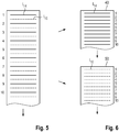
- Figure 5 schematically shows the interlaced line images I 14 (shown in normal lines) and I 16 (shown in dotted lines) captured by the camera.
- I 14 shown in normal lines
- I 16 shown in dotted lines
- Figure 5 schematically shows the interlaced line images I 14 (shown in normal lines) and I 16 (shown in dotted lines) captured by the camera.
- Only ten of the line images of each illumination condition are shown.
- several thousands of line images I 14 , I 16 are being captured for each sheet element 4.
- 4,000 line images I 14 and 4,000 line images I 16 are being captures for one sheet element 4 and that camera 12 is able to capture 80,000 line images per second, then ten sheet elements 4 per second can be processed.
- Figure 6 schematically shows how a reconstructed DFI image 40 is reconstructed from the line images I 14 and how a reconstructed BFI image 50 is reconstructed from line images I 16 .
- Image evaluation unit 18 processes the reconstructed images 40, 50 (either entirely or in those portions which are of interest) in order to detect an item of interest.
- the reconstructed images 40, 50 are compared in order to identify reflective surface portions.
- the surface inspection system 10 can be calibrated. This can be done either by placing a wide target in viewing area 20 or by moving a smaller target along the entire width of viewing area 20.
- each LED or each group of LEDs is energized at an adjusted level along each illuminator to provide the same signal on the target along the width of viewing area 20.
- the calibration is either used to adjust the operating power of the LEDs or to appropriately set the coefficient applied to the captured line images.
Landscapes
- Physics & Mathematics (AREA)
- Health & Medical Sciences (AREA)
- Life Sciences & Earth Sciences (AREA)
- Chemical & Material Sciences (AREA)
- Analytical Chemistry (AREA)
- Biochemistry (AREA)
- General Health & Medical Sciences (AREA)
- General Physics & Mathematics (AREA)
- Immunology (AREA)
- Pathology (AREA)
- Engineering & Computer Science (AREA)
- Textile Engineering (AREA)
- Investigating Materials By The Use Of Optical Means Adapted For Particular Applications (AREA)
Claims (15)
- Système d'inspection de surface (10) adapté pour déterminer la position de parties brillantes sur la surface d'éléments de feuille (4) présents dans une zone d'inspection (20), comprenant une unité d'évaluation d'image (18), une caméra (12), un illuminateur de champ sombre (14) et un illuminateur de champ clair (16), l'unité d'évaluation d'image (18) étant configurée pour soustraire une image de ligne capturée dans des conditions d'illumination en champ clair à partir d'une image de ligne capturée dans des conditions d'illumination en champ sombre, caractérisé en ce que l'intensité de la lumière provenant de l'illuminateur de champ sombre (14) est, au niveau de la caméra (12), la même que l'intensité de la lumière provenant de l'illuminateur de champ clair (16) lorsqu'un élément de feuille (4) est inspecté, qui présente une surface réfléchissante de manière diffuse.
- Système d'inspection de surface selon la revendication 1, dans lequel la caméra (12) est une caméra de ligne.
- Système d'inspection de surface selon la revendication 1 ou la revendication 2, dans lequel l'illuminateur de champ sombre (14) comprend une seule rangée de LED le long de laquelle sont fournis deux réflecteurs disposés de manière opposée.
- Système d'inspection de surface selon l'une quelconque des revendications précédentes, dans lequel l'illuminateur de champ clair (16) comprend une pluralité de rangées de LED qui sont disposées en parallèle.
- Système d'inspection de surface selon l'une quelconque des revendications précédentes, dans lequel le plan optique de l'illuminateur de champ sombre (14) est disposé à un angle d'environ 45° par rapport à un plan médian (M) qui est perpendiculaire à l'orientation de la zone de visualisation (20).
- Système d'inspection de surface selon l'une quelconque des revendications précédentes, dans lequel le plan optique de l'illuminateur de champ clair (16) est disposé à un angle d'environ 30° par rapport à un plan médian (M) qui est perpendiculaire à l'orientation de la zone de visualisation (20).
- Système d'inspection de surface selon l'une quelconque des revendications précédentes, dans lequel le plan de visualisation de la caméra (12) est disposé à un angle d'environ 20° par rapport à un plan médian (M) qui est perpendiculaire à l'orientation de la zone de visualisation (20).
- Système d'inspection de surface selon l'une quelconque des revendications précédentes, dans lequel la caméra (12) présente une résolution, à la surface de l'élément de feuille (4) à inspecter, dans la plage de 0,1 à 0,6 mm et de préférence de l'ordre de 0,3 mm.
- Procédé d'identification de zones de surface réfléchissante sur un élément de feuille (4) étant déplacé à travers une machine de traitement d'élément de feuille, en particulier en utilisant le système tel que défini dans l'une quelconque des revendications précédentes, dans lequel d'abord une image de ligne (I16) de la surface de l'élément de feuille (4) dans la zone de visualisation (20) est capturée dans des conditions d'illumination en champ clair et une image de ligne (I14) de la même surface de l'élément de feuille (4) dans la zone de visualisation (20) est capturée dans des conditions d'illumination en champ sombre, et dans lequel ensuite les deux images de ligne (I14, I16) sont comparées en étant soustraites l'une de l'autre, dans lequel la surface est identifiée comme étant réfléchissante si la différence (Sn) entre les deux images de ligne (I14, I16) est supérieure à un seuil prédéfini, caractérisé en ce que la puissance de l'illuminateur de champ sombre (14) et de l'illuminateur de champ clair (16) est réglée ou contrôlée de sorte que l'intensité de la lumière réfléchie vers la caméra (12) à partir d'une surface réfléchissante de manière diffuse d'élément de feuille (4) est la même pour les deux illuminateurs.
- Procédé selon la revendication 9, dans lequel les deux images de ligne (I14, I16) sont comparées en ce qui concerne leur intensité.
- Procédé selon la revendication 9 ou la revendication 10, dans lequel les images de ligne (I14, I16) sont comparées pixel par pixel.
- Procédé selon l'une quelconque des revendications 9 à 11, dans lequel une image reconstruite est créée sur la base des images de ligne capturées sous illumination en champ sombre et dans lequel une image reconstruite est créée sur la base des images de ligne capturées dans des conditions d'illumination en champ clair, et dans lequel des surfaces réfléchissantes sont identifiées en comparant les images reconstruites.
- Procédé selon l'une quelconque des revendications 9 à 12, dans lequel la caméra (12) est adaptée pour capturer plus de 10 000 images de ligne/s et de préférence plus de 20 000 images de ligne/s.
- Procédé selon l'une quelconque des revendications 9 à 13, dans lequel l'élément de feuille (4) est déplacé par rapport au système d'inspection de surface (10) à une vitesse de l'ordre de 5 à 15 m/s.
- Procédé selon l'une quelconque des revendications 9 à 14, dans lequel les éléments de feuille inspectés (4) présentent au moins partiellement une surface réfléchissante.
Applications Claiming Priority (2)
| Application Number | Priority Date | Filing Date | Title |
|---|---|---|---|
| EP16172031 | 2016-05-30 | ||
| PCT/EP2017/025150 WO2017207116A1 (fr) | 2016-05-30 | 2017-05-29 | Système d'inspection de surface et procédé d'inspection de surface |
Publications (2)
| Publication Number | Publication Date |
|---|---|
| EP3465155A1 EP3465155A1 (fr) | 2019-04-10 |
| EP3465155B1 true EP3465155B1 (fr) | 2021-09-22 |
Family
ID=56096519
Family Applications (1)
| Application Number | Title | Priority Date | Filing Date |
|---|---|---|---|
| EP17732308.6A Active EP3465155B1 (fr) | 2016-05-30 | 2017-05-29 | Système d'inspection de surface et procédé d'inspection de surface |
Country Status (9)
| Country | Link |
|---|---|
| US (1) | US11022553B2 (fr) |
| EP (1) | EP3465155B1 (fr) |
| JP (1) | JP6893219B2 (fr) |
| KR (2) | KR20200126025A (fr) |
| CN (1) | CN109313133B (fr) |
| BR (1) | BR112018071434B1 (fr) |
| CA (1) | CA3021912C (fr) |
| ES (1) | ES2894869T3 (fr) |
| WO (1) | WO2017207116A1 (fr) |
Families Citing this family (7)
| Publication number | Priority date | Publication date | Assignee | Title |
|---|---|---|---|---|
| CN108445008A (zh) * | 2018-02-27 | 2018-08-24 | 首钢京唐钢铁联合有限责任公司 | 一种带钢表面缺陷的检测方法 |
| JP2020094879A (ja) * | 2018-12-11 | 2020-06-18 | コニカミノルタ株式会社 | 加飾印刷検査装置、加飾印刷検査システム、加飾印刷検査方法、及び、プログラム |
| CN113507847B (zh) | 2019-03-05 | 2023-01-20 | 菲利普莫里斯生产公司 | 检查台和用于检查片材材料的方法 |
| DE102019107174B4 (de) * | 2019-03-20 | 2020-12-24 | Thyssenkrupp Rasselstein Gmbh | Verfahren und Vorrichtung zur Inspektion der Oberfläche eines sich bewegenden Bands |
| JP7476658B2 (ja) * | 2020-05-14 | 2024-05-01 | コニカミノルタ株式会社 | 画像検査装置、画像形成システム、画像検査方法、および画像検査プログラム |
| DE102022208364A1 (de) * | 2022-08-11 | 2024-02-22 | Bhs Corrugated Maschinen- Und Anlagenbau Gmbh | Wellpappenanlage sowie Verfahren zur Überwachung einer Wellpappenanlage |
| DE102022125409A1 (de) * | 2022-09-30 | 2024-04-04 | Cruse Technologies Gmbh | Verfahren und Vorrichtung zur Aufnahme mehrerer Abbildungen eines Objekts mit unterschiedlichen Beleuchtungskonfigurationen |
Family Cites Families (13)
| Publication number | Priority date | Publication date | Assignee | Title |
|---|---|---|---|---|
| US5087822A (en) | 1990-06-22 | 1992-02-11 | Alcan International Limited | Illumination system with incident beams from near and far dark field for high speed surface inspection of rolled aluminum sheet |
| US20020054291A1 (en) * | 1997-06-27 | 2002-05-09 | Tsai Bin-Ming Benjamin | Inspection system simultaneously utilizing monochromatic darkfield and broadband brightfield illumination sources |
| DE69703487T2 (de) | 1997-08-22 | 2001-06-13 | Fraunhofer Ges Forschung | Verfahren und Vorrichtung zur automatischen Prüfung bewegter Oberflächen |
| US6327374B1 (en) | 1999-02-18 | 2001-12-04 | Thermo Radiometrie Oy | Arrangement and method for inspection of surface quality |
| JP2000249660A (ja) | 1999-02-26 | 2000-09-14 | Idemitsu Petrochem Co Ltd | 表面検査装置および表面検査方法 |
| WO2000055605A1 (fr) * | 1999-03-18 | 2000-09-21 | Nkk Corporation | Procede et dispositif de marquage de defauts |
| JP3810599B2 (ja) | 1999-11-11 | 2006-08-16 | 株式会社リコー | 欠陥検出装置 |
| GB0606217D0 (en) * | 2006-03-29 | 2006-05-10 | Pilkington Plc | Glazing inspection |
| US7763876B2 (en) * | 2007-04-06 | 2010-07-27 | Xerox Corporation | Gloss and differential gloss measuring system |
| JP5585228B2 (ja) * | 2010-06-15 | 2014-09-10 | 株式会社リコー | 画像検査装置、画像検査方法、及び画像形成装置 |
| JP5806808B2 (ja) * | 2010-08-18 | 2015-11-10 | 倉敷紡績株式会社 | 撮像光学検査装置 |
| CN103486539B (zh) * | 2013-09-06 | 2016-09-14 | 广州市胜亚灯具制造有限公司 | 一种反光器 |
| CN104897693A (zh) | 2015-06-12 | 2015-09-09 | 武汉中导光电设备有限公司 | 一种玻璃表面缺陷增强装置及其检测方法 |
-
2017
- 2017-05-29 CA CA3021912A patent/CA3021912C/fr active Active
- 2017-05-29 WO PCT/EP2017/025150 patent/WO2017207116A1/fr unknown
- 2017-05-29 BR BR112018071434-8A patent/BR112018071434B1/pt active IP Right Grant
- 2017-05-29 CN CN201780033485.6A patent/CN109313133B/zh active Active
- 2017-05-29 ES ES17732308T patent/ES2894869T3/es active Active
- 2017-05-29 EP EP17732308.6A patent/EP3465155B1/fr active Active
- 2017-05-29 KR KR1020207031193A patent/KR20200126025A/ko not_active Application Discontinuation
- 2017-05-29 JP JP2018561965A patent/JP6893219B2/ja active Active
- 2017-05-29 KR KR1020187034671A patent/KR102291429B1/ko active IP Right Grant
- 2017-05-29 US US16/099,042 patent/US11022553B2/en active Active
Also Published As
| Publication number | Publication date |
|---|---|
| JP6893219B2 (ja) | 2021-06-23 |
| KR20200126025A (ko) | 2020-11-05 |
| KR102291429B1 (ko) | 2021-08-19 |
| CA3021912C (fr) | 2020-12-29 |
| US11022553B2 (en) | 2021-06-01 |
| WO2017207116A1 (fr) | 2017-12-07 |
| CA3021912A1 (fr) | 2017-12-07 |
| CN109313133B (zh) | 2021-09-03 |
| CN109313133A (zh) | 2019-02-05 |
| US20190154578A1 (en) | 2019-05-23 |
| BR112018071434B1 (pt) | 2022-12-27 |
| KR20190002637A (ko) | 2019-01-08 |
| EP3465155A1 (fr) | 2019-04-10 |
| JP2019517003A (ja) | 2019-06-20 |
| BR112018071434A2 (pt) | 2019-02-05 |
| ES2894869T3 (es) | 2022-02-16 |
Similar Documents
| Publication | Publication Date | Title |
|---|---|---|
| EP3465155B1 (fr) | Système d'inspection de surface et procédé d'inspection de surface | |
| EP1738136B1 (fr) | Dispositif de mesure et procede associe a un systeme de distribution | |
| US8041107B2 (en) | OVD (optical variable device) inspection method and inspection apparatus | |
| US11169095B2 (en) | Surface inspection system and method using multiple light sources and a camera offset therefrom | |
| CN103685830B (zh) | 图像读取装置以及纸张类处理装置 | |
| US8089045B2 (en) | Method and apparatus for raised material detection | |
| EP3465169B1 (fr) | Système de capture d'image et procédé permettant de déterminer la position d'une structure en relief sur un élément en feuille | |
| JP5297245B2 (ja) | 物体表面検査装置 | |
| JP6679942B2 (ja) | シートのキズ欠点検査装置 | |
| JP5787668B2 (ja) | 欠陥検出装置 | |
| JP2016148520A (ja) | キズ欠点検査装置およびキズ欠点検査方法 | |
| JP2009025073A (ja) | ロール状シート加工品の薄膜コート未塗工部の検査方法および検査装置 | |
| JP2005274442A (ja) | 光学式金属板表面検査装置 |
Legal Events
| Date | Code | Title | Description |
|---|---|---|---|
| STAA | Information on the status of an ep patent application or granted ep patent |
Free format text: STATUS: UNKNOWN |
|
| STAA | Information on the status of an ep patent application or granted ep patent |
Free format text: STATUS: THE INTERNATIONAL PUBLICATION HAS BEEN MADE |
|
| PUAI | Public reference made under article 153(3) epc to a published international application that has entered the european phase |
Free format text: ORIGINAL CODE: 0009012 |
|
| STAA | Information on the status of an ep patent application or granted ep patent |
Free format text: STATUS: REQUEST FOR EXAMINATION WAS MADE |
|
| 17P | Request for examination filed |
Effective date: 20181203 |
|
| AK | Designated contracting states |
Kind code of ref document: A1 Designated state(s): AL AT BE BG CH CY CZ DE DK EE ES FI FR GB GR HR HU IE IS IT LI LT LU LV MC MK MT NL NO PL PT RO RS SE SI SK SM TR |
|
| AX | Request for extension of the european patent |
Extension state: BA ME |
|
| STAA | Information on the status of an ep patent application or granted ep patent |
Free format text: STATUS: REQUEST FOR EXAMINATION WAS MADE |
|
| DAV | Request for validation of the european patent (deleted) | ||
| DAX | Request for extension of the european patent (deleted) | ||
| GRAP | Despatch of communication of intention to grant a patent |
Free format text: ORIGINAL CODE: EPIDOSNIGR1 |
|
| STAA | Information on the status of an ep patent application or granted ep patent |
Free format text: STATUS: GRANT OF PATENT IS INTENDED |
|
| INTG | Intention to grant announced |
Effective date: 20210713 |
|
| GRAS | Grant fee paid |
Free format text: ORIGINAL CODE: EPIDOSNIGR3 |
|
| GRAA | (expected) grant |
Free format text: ORIGINAL CODE: 0009210 |
|
| STAA | Information on the status of an ep patent application or granted ep patent |
Free format text: STATUS: THE PATENT HAS BEEN GRANTED |
|
| AK | Designated contracting states |
Kind code of ref document: B1 Designated state(s): AL AT BE BG CH CY CZ DE DK EE ES FI FR GB GR HR HU IE IS IT LI LT LU LV MC MK MT NL NO PL PT RO RS SE SI SK SM TR |
|
| REG | Reference to a national code |
Ref country code: GB Ref legal event code: FG4D |
|
| REG | Reference to a national code |
Ref country code: DE Ref legal event code: R096 Ref document number: 602017046374 Country of ref document: DE |
|
| REG | Reference to a national code |
Ref country code: IE Ref legal event code: FG4D |
|
| REG | Reference to a national code |
Ref country code: CH Ref legal event code: EP Ref country code: AT Ref legal event code: REF Ref document number: 1432705 Country of ref document: AT Kind code of ref document: T Effective date: 20211015 |
|
| REG | Reference to a national code |
Ref country code: LT Ref legal event code: MG9D |
|
| REG | Reference to a national code |
Ref country code: NL Ref legal event code: MP Effective date: 20210922 |
|
| PG25 | Lapsed in a contracting state [announced via postgrant information from national office to epo] |
Ref country code: SE Free format text: LAPSE BECAUSE OF FAILURE TO SUBMIT A TRANSLATION OF THE DESCRIPTION OR TO PAY THE FEE WITHIN THE PRESCRIBED TIME-LIMIT Effective date: 20210922 Ref country code: RS Free format text: LAPSE BECAUSE OF FAILURE TO SUBMIT A TRANSLATION OF THE DESCRIPTION OR TO PAY THE FEE WITHIN THE PRESCRIBED TIME-LIMIT Effective date: 20210922 Ref country code: HR Free format text: LAPSE BECAUSE OF FAILURE TO SUBMIT A TRANSLATION OF THE DESCRIPTION OR TO PAY THE FEE WITHIN THE PRESCRIBED TIME-LIMIT Effective date: 20210922 Ref country code: NO Free format text: LAPSE BECAUSE OF FAILURE TO SUBMIT A TRANSLATION OF THE DESCRIPTION OR TO PAY THE FEE WITHIN THE PRESCRIBED TIME-LIMIT Effective date: 20211222 Ref country code: FI Free format text: LAPSE BECAUSE OF FAILURE TO SUBMIT A TRANSLATION OF THE DESCRIPTION OR TO PAY THE FEE WITHIN THE PRESCRIBED TIME-LIMIT Effective date: 20210922 Ref country code: BG Free format text: LAPSE BECAUSE OF FAILURE TO SUBMIT A TRANSLATION OF THE DESCRIPTION OR TO PAY THE FEE WITHIN THE PRESCRIBED TIME-LIMIT Effective date: 20211222 Ref country code: LT Free format text: LAPSE BECAUSE OF FAILURE TO SUBMIT A TRANSLATION OF THE DESCRIPTION OR TO PAY THE FEE WITHIN THE PRESCRIBED TIME-LIMIT Effective date: 20210922 |
|
| REG | Reference to a national code |
Ref country code: AT Ref legal event code: MK05 Ref document number: 1432705 Country of ref document: AT Kind code of ref document: T Effective date: 20210922 |
|
| REG | Reference to a national code |
Ref country code: ES Ref legal event code: FG2A Ref document number: 2894869 Country of ref document: ES Kind code of ref document: T3 Effective date: 20220216 |
|
| PG25 | Lapsed in a contracting state [announced via postgrant information from national office to epo] |
Ref country code: LV Free format text: LAPSE BECAUSE OF FAILURE TO SUBMIT A TRANSLATION OF THE DESCRIPTION OR TO PAY THE FEE WITHIN THE PRESCRIBED TIME-LIMIT Effective date: 20210922 Ref country code: GR Free format text: LAPSE BECAUSE OF FAILURE TO SUBMIT A TRANSLATION OF THE DESCRIPTION OR TO PAY THE FEE WITHIN THE PRESCRIBED TIME-LIMIT Effective date: 20211223 |
|
| PG25 | Lapsed in a contracting state [announced via postgrant information from national office to epo] |
Ref country code: AT Free format text: LAPSE BECAUSE OF FAILURE TO SUBMIT A TRANSLATION OF THE DESCRIPTION OR TO PAY THE FEE WITHIN THE PRESCRIBED TIME-LIMIT Effective date: 20210922 |
|
| PG25 | Lapsed in a contracting state [announced via postgrant information from national office to epo] |
Ref country code: IS Free format text: LAPSE BECAUSE OF FAILURE TO SUBMIT A TRANSLATION OF THE DESCRIPTION OR TO PAY THE FEE WITHIN THE PRESCRIBED TIME-LIMIT Effective date: 20220122 Ref country code: SK Free format text: LAPSE BECAUSE OF FAILURE TO SUBMIT A TRANSLATION OF THE DESCRIPTION OR TO PAY THE FEE WITHIN THE PRESCRIBED TIME-LIMIT Effective date: 20210922 Ref country code: RO Free format text: LAPSE BECAUSE OF FAILURE TO SUBMIT A TRANSLATION OF THE DESCRIPTION OR TO PAY THE FEE WITHIN THE PRESCRIBED TIME-LIMIT Effective date: 20210922 Ref country code: PT Free format text: LAPSE BECAUSE OF FAILURE TO SUBMIT A TRANSLATION OF THE DESCRIPTION OR TO PAY THE FEE WITHIN THE PRESCRIBED TIME-LIMIT Effective date: 20220124 Ref country code: PL Free format text: LAPSE BECAUSE OF FAILURE TO SUBMIT A TRANSLATION OF THE DESCRIPTION OR TO PAY THE FEE WITHIN THE PRESCRIBED TIME-LIMIT Effective date: 20210922 Ref country code: NL Free format text: LAPSE BECAUSE OF FAILURE TO SUBMIT A TRANSLATION OF THE DESCRIPTION OR TO PAY THE FEE WITHIN THE PRESCRIBED TIME-LIMIT Effective date: 20210922 Ref country code: EE Free format text: LAPSE BECAUSE OF FAILURE TO SUBMIT A TRANSLATION OF THE DESCRIPTION OR TO PAY THE FEE WITHIN THE PRESCRIBED TIME-LIMIT Effective date: 20210922 Ref country code: CZ Free format text: LAPSE BECAUSE OF FAILURE TO SUBMIT A TRANSLATION OF THE DESCRIPTION OR TO PAY THE FEE WITHIN THE PRESCRIBED TIME-LIMIT Effective date: 20210922 Ref country code: AL Free format text: LAPSE BECAUSE OF FAILURE TO SUBMIT A TRANSLATION OF THE DESCRIPTION OR TO PAY THE FEE WITHIN THE PRESCRIBED TIME-LIMIT Effective date: 20210922 |
|
| REG | Reference to a national code |
Ref country code: DE Ref legal event code: R097 Ref document number: 602017046374 Country of ref document: DE |
|
| PG25 | Lapsed in a contracting state [announced via postgrant information from national office to epo] |
Ref country code: DK Free format text: LAPSE BECAUSE OF FAILURE TO SUBMIT A TRANSLATION OF THE DESCRIPTION OR TO PAY THE FEE WITHIN THE PRESCRIBED TIME-LIMIT Effective date: 20210922 |
|
| PLBE | No opposition filed within time limit |
Free format text: ORIGINAL CODE: 0009261 |
|
| STAA | Information on the status of an ep patent application or granted ep patent |
Free format text: STATUS: NO OPPOSITION FILED WITHIN TIME LIMIT |
|
| 26N | No opposition filed |
Effective date: 20220623 |
|
| PG25 | Lapsed in a contracting state [announced via postgrant information from national office to epo] |
Ref country code: SI Free format text: LAPSE BECAUSE OF FAILURE TO SUBMIT A TRANSLATION OF THE DESCRIPTION OR TO PAY THE FEE WITHIN THE PRESCRIBED TIME-LIMIT Effective date: 20210922 |
|
| REG | Reference to a national code |
Ref country code: BE Ref legal event code: MM Effective date: 20220531 |
|
| PG25 | Lapsed in a contracting state [announced via postgrant information from national office to epo] |
Ref country code: MC Free format text: LAPSE BECAUSE OF FAILURE TO SUBMIT A TRANSLATION OF THE DESCRIPTION OR TO PAY THE FEE WITHIN THE PRESCRIBED TIME-LIMIT Effective date: 20210922 Ref country code: LU Free format text: LAPSE BECAUSE OF NON-PAYMENT OF DUE FEES Effective date: 20220529 |
|
| PG25 | Lapsed in a contracting state [announced via postgrant information from national office to epo] |
Ref country code: IE Free format text: LAPSE BECAUSE OF NON-PAYMENT OF DUE FEES Effective date: 20220529 |
|
| PG25 | Lapsed in a contracting state [announced via postgrant information from national office to epo] |
Ref country code: BE Free format text: LAPSE BECAUSE OF NON-PAYMENT OF DUE FEES Effective date: 20220531 |
|
| P01 | Opt-out of the competence of the unified patent court (upc) registered |
Effective date: 20230519 |
|
| PGFP | Annual fee paid to national office [announced via postgrant information from national office to epo] |
Ref country code: IT Payment date: 20230412 Year of fee payment: 7 Ref country code: FR Payment date: 20230503 Year of fee payment: 7 Ref country code: ES Payment date: 20230605 Year of fee payment: 7 Ref country code: DE Payment date: 20230404 Year of fee payment: 7 Ref country code: CH Payment date: 20230602 Year of fee payment: 7 |
|
| PGFP | Annual fee paid to national office [announced via postgrant information from national office to epo] |
Ref country code: GB Payment date: 20230406 Year of fee payment: 7 |
|
| PG25 | Lapsed in a contracting state [announced via postgrant information from national office to epo] |
Ref country code: HU Free format text: LAPSE BECAUSE OF FAILURE TO SUBMIT A TRANSLATION OF THE DESCRIPTION OR TO PAY THE FEE WITHIN THE PRESCRIBED TIME-LIMIT; INVALID AB INITIO Effective date: 20170529 |
|
| PG25 | Lapsed in a contracting state [announced via postgrant information from national office to epo] |
Ref country code: SM Free format text: LAPSE BECAUSE OF FAILURE TO SUBMIT A TRANSLATION OF THE DESCRIPTION OR TO PAY THE FEE WITHIN THE PRESCRIBED TIME-LIMIT Effective date: 20210922 Ref country code: MK Free format text: LAPSE BECAUSE OF FAILURE TO SUBMIT A TRANSLATION OF THE DESCRIPTION OR TO PAY THE FEE WITHIN THE PRESCRIBED TIME-LIMIT Effective date: 20210922 Ref country code: CY Free format text: LAPSE BECAUSE OF FAILURE TO SUBMIT A TRANSLATION OF THE DESCRIPTION OR TO PAY THE FEE WITHIN THE PRESCRIBED TIME-LIMIT Effective date: 20210922 |