EP3464471B1 - Laminated sheet containing special siloxane block copolycarbonates as matrix material - Google Patents
Laminated sheet containing special siloxane block copolycarbonates as matrix material Download PDFInfo
- Publication number
- EP3464471B1 EP3464471B1 EP17727574.0A EP17727574A EP3464471B1 EP 3464471 B1 EP3464471 B1 EP 3464471B1 EP 17727574 A EP17727574 A EP 17727574A EP 3464471 B1 EP3464471 B1 EP 3464471B1
- Authority
- EP
- European Patent Office
- Prior art keywords
- composite material
- layers
- fiber
- fibre composite
- fibre
- Prior art date
- Legal status (The legal status is an assumption and is not a legal conclusion. Google has not performed a legal analysis and makes no representation as to the accuracy of the status listed.)
- Active
Links
- KPUWHANPEXNPJT-UHFFFAOYSA-N disiloxane Chemical class [SiH3]O[SiH3] KPUWHANPEXNPJT-UHFFFAOYSA-N 0.000 title claims description 45
- 239000011159 matrix material Substances 0.000 title description 38
- 239000000835 fiber Substances 0.000 claims description 257
- 239000002131 composite material Substances 0.000 claims description 160
- 239000011185 multilayer composite material Substances 0.000 claims description 80
- 229920000515 polycarbonate Polymers 0.000 claims description 68
- 239000004417 polycarbonate Substances 0.000 claims description 64
- 238000000034 method Methods 0.000 claims description 48
- -1 polysiloxane Polymers 0.000 claims description 40
- 239000000463 material Substances 0.000 claims description 30
- 230000008569 process Effects 0.000 claims description 29
- 239000000203 mixture Substances 0.000 claims description 22
- 229920001169 thermoplastic Polymers 0.000 claims description 21
- 239000004416 thermosoftening plastic Substances 0.000 claims description 21
- 239000003365 glass fiber Substances 0.000 claims description 17
- 125000002496 methyl group Chemical group [H]C([H])([H])* 0.000 claims description 17
- 230000009477 glass transition Effects 0.000 claims description 10
- 125000003118 aryl group Chemical group 0.000 claims description 9
- 229920001296 polysiloxane Polymers 0.000 claims description 9
- 125000005842 heteroatom Chemical group 0.000 claims description 6
- 239000001257 hydrogen Substances 0.000 claims description 6
- 229910052739 hydrogen Inorganic materials 0.000 claims description 6
- 125000004051 hexyl group Chemical group [H]C([H])([H])C([H])([H])C([H])([H])C([H])([H])C([H])([H])C([H])([H])* 0.000 claims description 5
- 229910052736 halogen Inorganic materials 0.000 claims description 4
- 150000002367 halogens Chemical class 0.000 claims description 4
- 125000006702 (C1-C18) alkyl group Chemical group 0.000 claims description 3
- OKTJSMMVPCPJKN-UHFFFAOYSA-N Carbon Chemical compound [C] OKTJSMMVPCPJKN-UHFFFAOYSA-N 0.000 claims description 3
- 125000003710 aryl alkyl group Chemical group 0.000 claims description 3
- 229910052799 carbon Inorganic materials 0.000 claims description 3
- 238000010276 construction Methods 0.000 claims description 3
- 125000005028 dihydroxyaryl group Chemical group 0.000 claims description 2
- 125000004435 hydrogen atom Chemical group [H]* 0.000 claims 2
- 125000003107 substituted aryl group Chemical group 0.000 claims 1
- 239000010410 layer Substances 0.000 description 193
- 229920003023 plastic Polymers 0.000 description 33
- 239000004033 plastic Substances 0.000 description 33
- 238000004519 manufacturing process Methods 0.000 description 29
- 229920000642 polymer Polymers 0.000 description 28
- 239000004744 fabric Substances 0.000 description 23
- 238000012360 testing method Methods 0.000 description 20
- 239000002657 fibrous material Substances 0.000 description 18
- 239000000126 substance Substances 0.000 description 17
- IISBACLAFKSPIT-UHFFFAOYSA-N bisphenol A Chemical compound C=1C=C(O)C=CC=1C(C)(C)C1=CC=C(O)C=C1 IISBACLAFKSPIT-UHFFFAOYSA-N 0.000 description 15
- 239000011800 void material Substances 0.000 description 11
- 239000000654 additive Substances 0.000 description 10
- 229920000049 Carbon (fiber) Polymers 0.000 description 8
- 125000002947 alkylene group Chemical group 0.000 description 8
- 239000011888 foil Substances 0.000 description 8
- 238000012545 processing Methods 0.000 description 8
- RIOQSEWOXXDEQQ-UHFFFAOYSA-N triphenylphosphine Chemical compound C1=CC=CC=C1P(C=1C=CC=CC=1)C1=CC=CC=C1 RIOQSEWOXXDEQQ-UHFFFAOYSA-N 0.000 description 8
- PPBRXRYQALVLMV-UHFFFAOYSA-N Styrene Chemical compound C=CC1=CC=CC=C1 PPBRXRYQALVLMV-UHFFFAOYSA-N 0.000 description 7
- 125000003545 alkoxy group Chemical group 0.000 description 7
- 239000004917 carbon fiber Substances 0.000 description 7
- 150000001875 compounds Chemical class 0.000 description 7
- 239000000155 melt Substances 0.000 description 7
- UFHFLCQGNIYNRP-UHFFFAOYSA-N Hydrogen Chemical compound [H][H] UFHFLCQGNIYNRP-UHFFFAOYSA-N 0.000 description 6
- DGAQECJNVWCQMB-PUAWFVPOSA-M Ilexoside XXIX Chemical compound C[C@@H]1CC[C@@]2(CC[C@@]3(C(=CC[C@H]4[C@]3(CC[C@@H]5[C@@]4(CC[C@@H](C5(C)C)OS(=O)(=O)[O-])C)C)[C@@H]2[C@]1(C)O)C)C(=O)O[C@H]6[C@@H]([C@H]([C@@H]([C@H](O6)CO)O)O)O.[Na+] DGAQECJNVWCQMB-PUAWFVPOSA-M 0.000 description 6
- 239000004594 Masterbatch (MB) Substances 0.000 description 6
- 125000001118 alkylidene group Chemical group 0.000 description 6
- 230000008901 benefit Effects 0.000 description 6
- 230000015572 biosynthetic process Effects 0.000 description 6
- 239000003054 catalyst Substances 0.000 description 6
- 238000001125 extrusion Methods 0.000 description 6
- 238000011068 loading method Methods 0.000 description 6
- 229920000728 polyester Polymers 0.000 description 6
- 150000003254 radicals Chemical class 0.000 description 6
- 239000000523 sample Substances 0.000 description 6
- 229910052708 sodium Inorganic materials 0.000 description 6
- 239000011734 sodium Substances 0.000 description 6
- 239000000243 solution Substances 0.000 description 6
- 239000004952 Polyamide Substances 0.000 description 5
- 238000005452 bending Methods 0.000 description 5
- 239000003795 chemical substances by application Substances 0.000 description 5
- 230000007547 defect Effects 0.000 description 5
- 239000004922 lacquer Substances 0.000 description 5
- ISWSIDIOOBJBQZ-UHFFFAOYSA-N phenol group Chemical group C1(=CC=CC=C1)O ISWSIDIOOBJBQZ-UHFFFAOYSA-N 0.000 description 5
- 229920002647 polyamide Polymers 0.000 description 5
- 229920005989 resin Polymers 0.000 description 5
- 239000011347 resin Substances 0.000 description 5
- QIGBRXMKCJKVMJ-UHFFFAOYSA-N Hydroquinone Chemical compound OC1=CC=C(O)C=C1 QIGBRXMKCJKVMJ-UHFFFAOYSA-N 0.000 description 4
- ATUOYWHBWRKTHZ-UHFFFAOYSA-N Propane Chemical compound CCC ATUOYWHBWRKTHZ-UHFFFAOYSA-N 0.000 description 4
- GWEVSGVZZGPLCZ-UHFFFAOYSA-N Titan oxide Chemical compound O=[Ti]=O GWEVSGVZZGPLCZ-UHFFFAOYSA-N 0.000 description 4
- 229920001577 copolymer Polymers 0.000 description 4
- 238000005227 gel permeation chromatography Methods 0.000 description 4
- 238000010438 heat treatment Methods 0.000 description 4
- 125000000654 isopropylidene group Chemical group C(C)(C)=* 0.000 description 4
- 238000002844 melting Methods 0.000 description 4
- 229910052751 metal Inorganic materials 0.000 description 4
- 239000002184 metal Substances 0.000 description 4
- 239000006082 mold release agent Substances 0.000 description 4
- 229920001601 polyetherimide Polymers 0.000 description 4
- 230000035882 stress Effects 0.000 description 4
- ZLLNYWQSSYUXJM-UHFFFAOYSA-M tetraphenylphosphanium;phenoxide Chemical compound [O-]C1=CC=CC=C1.C1=CC=CC=C1[P+](C=1C=CC=CC=1)(C=1C=CC=CC=1)C1=CC=CC=C1 ZLLNYWQSSYUXJM-UHFFFAOYSA-M 0.000 description 4
- 229920002554 vinyl polymer Polymers 0.000 description 4
- 125000004209 (C1-C8) alkyl group Chemical group 0.000 description 3
- WEVYAHXRMPXWCK-UHFFFAOYSA-N Acetonitrile Chemical compound CC#N WEVYAHXRMPXWCK-UHFFFAOYSA-N 0.000 description 3
- YMWUJEATGCHHMB-UHFFFAOYSA-N Dichloromethane Chemical compound ClCCl YMWUJEATGCHHMB-UHFFFAOYSA-N 0.000 description 3
- 239000004593 Epoxy Substances 0.000 description 3
- 239000004696 Poly ether ether ketone Substances 0.000 description 3
- 239000004734 Polyphenylene sulfide Substances 0.000 description 3
- 239000004793 Polystyrene Substances 0.000 description 3
- 239000006096 absorbing agent Substances 0.000 description 3
- 229920002678 cellulose Polymers 0.000 description 3
- 238000001816 cooling Methods 0.000 description 3
- 238000001514 detection method Methods 0.000 description 3
- 238000005470 impregnation Methods 0.000 description 3
- 239000007788 liquid Substances 0.000 description 3
- 230000008018 melting Effects 0.000 description 3
- VNWKTOKETHGBQD-UHFFFAOYSA-N methane Chemical compound C VNWKTOKETHGBQD-UHFFFAOYSA-N 0.000 description 3
- 239000001301 oxygen Substances 0.000 description 3
- 229910052760 oxygen Inorganic materials 0.000 description 3
- 229920001707 polybutylene terephthalate Polymers 0.000 description 3
- 229920002530 polyetherether ketone Polymers 0.000 description 3
- 229920000139 polyethylene terephthalate Polymers 0.000 description 3
- 239000005020 polyethylene terephthalate Substances 0.000 description 3
- 229920006324 polyoxymethylene Polymers 0.000 description 3
- 229920000069 polyphenylene sulfide Polymers 0.000 description 3
- 229920002223 polystyrene Polymers 0.000 description 3
- 238000012552 review Methods 0.000 description 3
- 239000000758 substrate Substances 0.000 description 3
- 239000003017 thermal stabilizer Substances 0.000 description 3
- 239000012815 thermoplastic material Substances 0.000 description 3
- NAWXUBYGYWOOIX-SFHVURJKSA-N (2s)-2-[[4-[2-(2,4-diaminoquinazolin-6-yl)ethyl]benzoyl]amino]-4-methylidenepentanedioic acid Chemical compound C1=CC2=NC(N)=NC(N)=C2C=C1CCC1=CC=C(C(=O)N[C@@H](CC(=C)C(O)=O)C(O)=O)C=C1 NAWXUBYGYWOOIX-SFHVURJKSA-N 0.000 description 2
- 125000004400 (C1-C12) alkyl group Chemical group 0.000 description 2
- 125000004191 (C1-C6) alkoxy group Chemical group 0.000 description 2
- 150000005208 1,4-dihydroxybenzenes Chemical class 0.000 description 2
- UMPGNGRIGSEMTC-UHFFFAOYSA-N 4-[1-(4-hydroxyphenyl)-3,3,5-trimethylcyclohexyl]phenol Chemical compound C1C(C)CC(C)(C)CC1(C=1C=CC(O)=CC=1)C1=CC=C(O)C=C1 UMPGNGRIGSEMTC-UHFFFAOYSA-N 0.000 description 2
- PVFQHGDIOXNKIC-UHFFFAOYSA-N 4-[2-[3-[2-(4-hydroxyphenyl)propan-2-yl]phenyl]propan-2-yl]phenol Chemical compound C=1C=CC(C(C)(C)C=2C=CC(O)=CC=2)=CC=1C(C)(C)C1=CC=C(O)C=C1 PVFQHGDIOXNKIC-UHFFFAOYSA-N 0.000 description 2
- 125000004203 4-hydroxyphenyl group Chemical group [H]OC1=C([H])C([H])=C(*)C([H])=C1[H] 0.000 description 2
- NIXOWILDQLNWCW-UHFFFAOYSA-N Acrylic acid Chemical compound OC(=O)C=C NIXOWILDQLNWCW-UHFFFAOYSA-N 0.000 description 2
- 229920000106 Liquid crystal polymer Polymers 0.000 description 2
- 229920004042 Makrolon® 2608 Polymers 0.000 description 2
- 229920004061 Makrolon® 3108 Polymers 0.000 description 2
- 239000004697 Polyetherimide Substances 0.000 description 2
- 239000004642 Polyimide Substances 0.000 description 2
- WQDUMFSSJAZKTM-UHFFFAOYSA-N Sodium methoxide Chemical compound [Na+].[O-]C WQDUMFSSJAZKTM-UHFFFAOYSA-N 0.000 description 2
- 229910000831 Steel Inorganic materials 0.000 description 2
- 239000004433 Thermoplastic polyurethane Substances 0.000 description 2
- OCKWAZCWKSMKNC-UHFFFAOYSA-N [3-octadecanoyloxy-2,2-bis(octadecanoyloxymethyl)propyl] octadecanoate Chemical compound CCCCCCCCCCCCCCCCCC(=O)OCC(COC(=O)CCCCCCCCCCCCCCCCC)(COC(=O)CCCCCCCCCCCCCCCCC)COC(=O)CCCCCCCCCCCCCCCCC OCKWAZCWKSMKNC-UHFFFAOYSA-N 0.000 description 2
- 230000009471 action Effects 0.000 description 2
- 239000000853 adhesive Substances 0.000 description 2
- 230000001070 adhesive effect Effects 0.000 description 2
- 229920003235 aromatic polyamide Polymers 0.000 description 2
- 238000004380 ashing Methods 0.000 description 2
- QVGXLLKOCUKJST-UHFFFAOYSA-N atomic oxygen Chemical compound [O] QVGXLLKOCUKJST-UHFFFAOYSA-N 0.000 description 2
- 230000001914 calming effect Effects 0.000 description 2
- 230000000052 comparative effect Effects 0.000 description 2
- 238000013329 compounding Methods 0.000 description 2
- 238000002591 computed tomography Methods 0.000 description 2
- 238000005336 cracking Methods 0.000 description 2
- 239000013078 crystal Substances 0.000 description 2
- 238000013461 design Methods 0.000 description 2
- 239000004205 dimethyl polysiloxane Substances 0.000 description 2
- 238000009826 distribution Methods 0.000 description 2
- 238000005516 engineering process Methods 0.000 description 2
- 150000002148 esters Chemical class 0.000 description 2
- 150000002170 ethers Chemical class 0.000 description 2
- 238000011156 evaluation Methods 0.000 description 2
- 239000000945 filler Substances 0.000 description 2
- 239000007789 gas Substances 0.000 description 2
- 239000011521 glass Substances 0.000 description 2
- 239000008187 granular material Substances 0.000 description 2
- 238000004128 high performance liquid chromatography Methods 0.000 description 2
- 238000005304 joining Methods 0.000 description 2
- 238000003475 lamination Methods 0.000 description 2
- 238000005259 measurement Methods 0.000 description 2
- 238000000386 microscopy Methods 0.000 description 2
- SSDSCDGVMJFTEQ-UHFFFAOYSA-N octadecyl 3-(3,5-ditert-butyl-4-hydroxyphenyl)propanoate Chemical compound CCCCCCCCCCCCCCCCCCOC(=O)CCC1=CC(C(C)(C)C)=C(O)C(C(C)(C)C)=C1 SSDSCDGVMJFTEQ-UHFFFAOYSA-N 0.000 description 2
- 239000003973 paint Substances 0.000 description 2
- 229920000435 poly(dimethylsiloxane) Polymers 0.000 description 2
- 229920001643 poly(ether ketone) Polymers 0.000 description 2
- 229920002239 polyacrylonitrile Polymers 0.000 description 2
- 229920001721 polyimide Polymers 0.000 description 2
- 229920000098 polyolefin Polymers 0.000 description 2
- 229920002635 polyurethane Chemical class 0.000 description 2
- 239000004814 polyurethane Chemical class 0.000 description 2
- 239000000843 powder Substances 0.000 description 2
- 239000000047 product Substances 0.000 description 2
- 239000001294 propane Substances 0.000 description 2
- 230000005855 radiation Effects 0.000 description 2
- 230000008707 rearrangement Effects 0.000 description 2
- GHMLBKRAJCXXBS-UHFFFAOYSA-N resorcinol Chemical compound OC1=CC=CC(O)=C1 GHMLBKRAJCXXBS-UHFFFAOYSA-N 0.000 description 2
- 238000007127 saponification reaction Methods 0.000 description 2
- 239000011265 semifinished product Substances 0.000 description 2
- 150000004756 silanes Chemical class 0.000 description 2
- 238000004513 sizing Methods 0.000 description 2
- 239000007858 starting material Substances 0.000 description 2
- 230000003068 static effect Effects 0.000 description 2
- 239000010959 steel Substances 0.000 description 2
- 230000001360 synchronised effect Effects 0.000 description 2
- 229920002803 thermoplastic polyurethane Polymers 0.000 description 2
- 238000005809 transesterification reaction Methods 0.000 description 2
- HVLLSGMXQDNUAL-UHFFFAOYSA-N triphenyl phosphite Chemical compound C=1C=CC=CC=1OP(OC=1C=CC=CC=1)OC1=CC=CC=C1 HVLLSGMXQDNUAL-UHFFFAOYSA-N 0.000 description 2
- WGKLOLBTFWFKOD-UHFFFAOYSA-N tris(2-nonylphenyl) phosphite Chemical compound CCCCCCCCCC1=CC=CC=C1OP(OC=1C(=CC=CC=1)CCCCCCCCC)OC1=CC=CC=C1CCCCCCCCC WGKLOLBTFWFKOD-UHFFFAOYSA-N 0.000 description 2
- 239000002759 woven fabric Substances 0.000 description 2
- JYNDYSWJBQLMHI-UHFFFAOYSA-N (2,4-dihydroxyphenyl)-phenylmethanone;diphenylmethanone Chemical compound C=1C=CC=CC=1C(=O)C1=CC=CC=C1.OC1=CC(O)=CC=C1C(=O)C1=CC=CC=C1 JYNDYSWJBQLMHI-UHFFFAOYSA-N 0.000 description 1
- WYTZZXDRDKSJID-UHFFFAOYSA-N (3-aminopropyl)triethoxysilane Chemical compound CCO[Si](OCC)(OCC)CCCN WYTZZXDRDKSJID-UHFFFAOYSA-N 0.000 description 1
- 125000003161 (C1-C6) alkylene group Chemical group 0.000 description 1
- WKBPZYKAUNRMKP-UHFFFAOYSA-N 1-[2-(2,4-dichlorophenyl)pentyl]1,2,4-triazole Chemical compound C=1C=C(Cl)C=C(Cl)C=1C(CCC)CN1C=NC=N1 WKBPZYKAUNRMKP-UHFFFAOYSA-N 0.000 description 1
- UAXNXOMKCGKNCI-UHFFFAOYSA-N 1-diphenylphosphanylethyl(diphenyl)phosphane Chemical compound C=1C=CC=CC=1P(C=1C=CC=CC=1)C(C)P(C=1C=CC=CC=1)C1=CC=CC=C1 UAXNXOMKCGKNCI-UHFFFAOYSA-N 0.000 description 1
- VBICKXHEKHSIBG-UHFFFAOYSA-N 1-monostearoylglycerol Chemical compound CCCCCCCCCCCCCCCCCC(=O)OCC(O)CO VBICKXHEKHSIBG-UHFFFAOYSA-N 0.000 description 1
- YIYBRXKMQFDHSM-UHFFFAOYSA-N 2,2'-Dihydroxybenzophenone Chemical class OC1=CC=CC=C1C(=O)C1=CC=CC=C1O YIYBRXKMQFDHSM-UHFFFAOYSA-N 0.000 description 1
- VXHYVVAUHMGCEX-UHFFFAOYSA-N 2-(2-hydroxyphenoxy)phenol Chemical class OC1=CC=CC=C1OC1=CC=CC=C1O VXHYVVAUHMGCEX-UHFFFAOYSA-N 0.000 description 1
- BLDLRWQLBOJPEB-UHFFFAOYSA-N 2-(2-hydroxyphenyl)sulfanylphenol Chemical class OC1=CC=CC=C1SC1=CC=CC=C1O BLDLRWQLBOJPEB-UHFFFAOYSA-N 0.000 description 1
- XSVZEASGNTZBRQ-UHFFFAOYSA-N 2-(2-hydroxyphenyl)sulfinylphenol Chemical class OC1=CC=CC=C1S(=O)C1=CC=CC=C1O XSVZEASGNTZBRQ-UHFFFAOYSA-N 0.000 description 1
- QUWAJPZDCZDTJS-UHFFFAOYSA-N 2-(2-hydroxyphenyl)sulfonylphenol Chemical class OC1=CC=CC=C1S(=O)(=O)C1=CC=CC=C1O QUWAJPZDCZDTJS-UHFFFAOYSA-N 0.000 description 1
- XKZQKPRCPNGNFR-UHFFFAOYSA-N 2-(3-hydroxyphenyl)phenol Chemical compound OC1=CC=CC(C=2C(=CC=CC=2)O)=C1 XKZQKPRCPNGNFR-UHFFFAOYSA-N 0.000 description 1
- LEVFXWNQQSSNAC-UHFFFAOYSA-N 2-(4,6-diphenyl-1,3,5-triazin-2-yl)-5-hexoxyphenol Chemical compound OC1=CC(OCCCCCC)=CC=C1C1=NC(C=2C=CC=CC=2)=NC(C=2C=CC=CC=2)=N1 LEVFXWNQQSSNAC-UHFFFAOYSA-N 0.000 description 1
- KIPGIZCKZDHTJB-UHFFFAOYSA-N 2-(4-phenylphenyl)-1,3,5-triazine Chemical compound C1=CC=CC=C1C1=CC=C(C=2N=CN=CN=2)C=C1 KIPGIZCKZDHTJB-UHFFFAOYSA-N 0.000 description 1
- IYAZLDLPUNDVAG-UHFFFAOYSA-N 2-(benzotriazol-2-yl)-4-(2,4,4-trimethylpentan-2-yl)phenol Chemical compound CC(C)(C)CC(C)(C)C1=CC=C(O)C(N2N=C3C=CC=CC3=N2)=C1 IYAZLDLPUNDVAG-UHFFFAOYSA-N 0.000 description 1
- RTNVDKBRTXEWQE-UHFFFAOYSA-N 2-(benzotriazol-2-yl)-6-butan-2-yl-4-tert-butylphenol Chemical compound CCC(C)C1=CC(C(C)(C)C)=CC(N2N=C3C=CC=CC3=N2)=C1O RTNVDKBRTXEWQE-UHFFFAOYSA-N 0.000 description 1
- JMTMSDXUXJISAY-UHFFFAOYSA-N 2H-benzotriazol-4-ol Chemical class OC1=CC=CC2=C1N=NN2 JMTMSDXUXJISAY-UHFFFAOYSA-N 0.000 description 1
- YMTYZTXUZLQUSF-UHFFFAOYSA-N 3,3'-Dimethylbisphenol A Chemical compound C1=C(O)C(C)=CC(C(C)(C)C=2C=C(C)C(O)=CC=2)=C1 YMTYZTXUZLQUSF-UHFFFAOYSA-N 0.000 description 1
- SJECZPVISLOESU-UHFFFAOYSA-N 3-trimethoxysilylpropan-1-amine Chemical compound CO[Si](OC)(OC)CCCN SJECZPVISLOESU-UHFFFAOYSA-N 0.000 description 1
- SUCTVKDVODFXFX-UHFFFAOYSA-N 4-(4-hydroxy-3,5-dimethylphenyl)sulfonyl-2,6-dimethylphenol Chemical compound CC1=C(O)C(C)=CC(S(=O)(=O)C=2C=C(C)C(O)=C(C)C=2)=C1 SUCTVKDVODFXFX-UHFFFAOYSA-N 0.000 description 1
- AZZWZMUXHALBCQ-UHFFFAOYSA-N 4-[(4-hydroxy-3,5-dimethylphenyl)methyl]-2,6-dimethylphenol Chemical compound CC1=C(O)C(C)=CC(CC=2C=C(C)C(O)=C(C)C=2)=C1 AZZWZMUXHALBCQ-UHFFFAOYSA-N 0.000 description 1
- ODJUOZPKKHIEOZ-UHFFFAOYSA-N 4-[2-(4-hydroxy-3,5-dimethylphenyl)propan-2-yl]-2,6-dimethylphenol Chemical compound CC1=C(O)C(C)=CC(C(C)(C)C=2C=C(C)C(O)=C(C)C=2)=C1 ODJUOZPKKHIEOZ-UHFFFAOYSA-N 0.000 description 1
- DUKMWXLEZOCRSO-UHFFFAOYSA-N 4-[2-(4-hydroxyphenyl)-1-phenylpropan-2-yl]phenol Chemical compound C=1C=C(O)C=CC=1C(C=1C=CC(O)=CC=1)(C)CC1=CC=CC=C1 DUKMWXLEZOCRSO-UHFFFAOYSA-N 0.000 description 1
- YICHMIMRBUIUJT-UHFFFAOYSA-N 4-[2-[3-[2-(4-hydroxy-3,5-dimethylphenyl)propan-2-yl]phenyl]propan-2-yl]-2,6-dimethylphenol Chemical compound CC1=C(O)C(C)=CC(C(C)(C)C=2C=C(C=CC=2)C(C)(C)C=2C=C(C)C(O)=C(C)C=2)=C1 YICHMIMRBUIUJT-UHFFFAOYSA-N 0.000 description 1
- OBZFGWBLZXIBII-UHFFFAOYSA-N 4-[3-(4-hydroxy-3,5-dimethylphenyl)-3-methylbutyl]-2,6-dimethylphenol Chemical compound CC1=C(O)C(C)=CC(CCC(C)(C)C=2C=C(C)C(O)=C(C)C=2)=C1 OBZFGWBLZXIBII-UHFFFAOYSA-N 0.000 description 1
- NIRYBKWMEWFDPM-UHFFFAOYSA-N 4-[3-(4-hydroxyphenyl)-3-methylbutyl]phenol Chemical compound C=1C=C(O)C=CC=1C(C)(C)CCC1=CC=C(O)C=C1 NIRYBKWMEWFDPM-UHFFFAOYSA-N 0.000 description 1
- SWDDLRSGGCWDPH-UHFFFAOYSA-N 4-triethoxysilylbutan-1-amine Chemical compound CCO[Si](OCC)(OCC)CCCCN SWDDLRSGGCWDPH-UHFFFAOYSA-N 0.000 description 1
- RBVMDQYCJXEJCJ-UHFFFAOYSA-N 4-trimethoxysilylbutan-1-amine Chemical compound CO[Si](OC)(OC)CCCCN RBVMDQYCJXEJCJ-UHFFFAOYSA-N 0.000 description 1
- BWDBEAQIHAEVLV-UHFFFAOYSA-N 6-methylheptan-1-ol Chemical compound CC(C)CCCCCO BWDBEAQIHAEVLV-UHFFFAOYSA-N 0.000 description 1
- NIXOWILDQLNWCW-UHFFFAOYSA-M Acrylate Chemical compound [O-]C(=O)C=C NIXOWILDQLNWCW-UHFFFAOYSA-M 0.000 description 1
- NLHHRLWOUZZQLW-UHFFFAOYSA-N Acrylonitrile Chemical compound C=CC#N NLHHRLWOUZZQLW-UHFFFAOYSA-N 0.000 description 1
- SDDLEVPIDBLVHC-UHFFFAOYSA-N Bisphenol Z Chemical compound C1=CC(O)=CC=C1C1(C=2C=CC(O)=CC=2)CCCCC1 SDDLEVPIDBLVHC-UHFFFAOYSA-N 0.000 description 1
- ZOXJGFHDIHLPTG-UHFFFAOYSA-N Boron Chemical compound [B] ZOXJGFHDIHLPTG-UHFFFAOYSA-N 0.000 description 1
- BVKZGUZCCUSVTD-UHFFFAOYSA-L Carbonate Chemical compound [O-]C([O-])=O BVKZGUZCCUSVTD-UHFFFAOYSA-L 0.000 description 1
- 229920000742 Cotton Polymers 0.000 description 1
- MYMOFIZGZYHOMD-UHFFFAOYSA-N Dioxygen Chemical compound O=O MYMOFIZGZYHOMD-UHFFFAOYSA-N 0.000 description 1
- JOYRKODLDBILNP-UHFFFAOYSA-N Ethyl urethane Chemical compound CCOC(N)=O JOYRKODLDBILNP-UHFFFAOYSA-N 0.000 description 1
- FMRHJJZUHUTGKE-UHFFFAOYSA-N Ethylhexyl salicylate Chemical compound CCCCC(CC)COC(=O)C1=CC=CC=C1O FMRHJJZUHUTGKE-UHFFFAOYSA-N 0.000 description 1
- 102100040287 GTP cyclohydrolase 1 feedback regulatory protein Human genes 0.000 description 1
- 101710185324 GTP cyclohydrolase 1 feedback regulatory protein Proteins 0.000 description 1
- 239000004977 Liquid-crystal polymers (LCPs) Substances 0.000 description 1
- 239000006057 Non-nutritive feed additive Substances 0.000 description 1
- 229920002292 Nylon 6 Polymers 0.000 description 1
- BPQQTUXANYXVAA-UHFFFAOYSA-N Orthosilicate Chemical compound [O-][Si]([O-])([O-])[O-] BPQQTUXANYXVAA-UHFFFAOYSA-N 0.000 description 1
- 229930040373 Paraformaldehyde Natural products 0.000 description 1
- JKIJEFPNVSHHEI-UHFFFAOYSA-N Phenol, 2,4-bis(1,1-dimethylethyl)-, phosphite (3:1) Chemical compound CC(C)(C)C1=CC(C(C)(C)C)=CC=C1OP(OC=1C(=CC(=CC=1)C(C)(C)C)C(C)(C)C)OC1=CC=C(C(C)(C)C)C=C1C(C)(C)C JKIJEFPNVSHHEI-UHFFFAOYSA-N 0.000 description 1
- 239000004962 Polyamide-imide Substances 0.000 description 1
- 239000004695 Polyether sulfone Substances 0.000 description 1
- 239000004698 Polyethylene Substances 0.000 description 1
- 239000004743 Polypropylene Substances 0.000 description 1
- 229920001328 Polyvinylidene chloride Polymers 0.000 description 1
- XUIMIQQOPSSXEZ-UHFFFAOYSA-N Silicon Chemical compound [Si] XUIMIQQOPSSXEZ-UHFFFAOYSA-N 0.000 description 1
- 230000006750 UV protection Effects 0.000 description 1
- 239000012963 UV stabilizer Substances 0.000 description 1
- 150000001241 acetals Chemical class 0.000 description 1
- XECAHXYUAAWDEL-UHFFFAOYSA-N acrylonitrile butadiene styrene Chemical compound C=CC=C.C=CC#N.C=CC1=CC=CC=C1 XECAHXYUAAWDEL-UHFFFAOYSA-N 0.000 description 1
- 239000004676 acrylonitrile butadiene styrene Substances 0.000 description 1
- 229920000122 acrylonitrile butadiene styrene Polymers 0.000 description 1
- 230000000996 additive effect Effects 0.000 description 1
- 238000004026 adhesive bonding Methods 0.000 description 1
- 150000001335 aliphatic alkanes Chemical class 0.000 description 1
- 125000001931 aliphatic group Chemical group 0.000 description 1
- 125000002877 alkyl aryl group Chemical group 0.000 description 1
- 125000000217 alkyl group Chemical group 0.000 description 1
- 150000001412 amines Chemical class 0.000 description 1
- 239000002216 antistatic agent Substances 0.000 description 1
- 238000013459 approach Methods 0.000 description 1
- 239000007864 aqueous solution Substances 0.000 description 1
- 239000012964 benzotriazole Substances 0.000 description 1
- VCCBEIPGXKNHFW-UHFFFAOYSA-N biphenyl-4,4'-diol Chemical group C1=CC(O)=CC=C1C1=CC=C(O)C=C1 VCCBEIPGXKNHFW-UHFFFAOYSA-N 0.000 description 1
- 229920000402 bisphenol A polycarbonate polymer Polymers 0.000 description 1
- 229920001400 block copolymer Polymers 0.000 description 1
- 229910052796 boron Inorganic materials 0.000 description 1
- 239000006085 branching agent Substances 0.000 description 1
- 238000004364 calculation method Methods 0.000 description 1
- 239000003990 capacitor Substances 0.000 description 1
- 125000004432 carbon atom Chemical group C* 0.000 description 1
- 150000004649 carbonic acid derivatives Chemical class 0.000 description 1
- 238000005266 casting Methods 0.000 description 1
- 230000015556 catabolic process Effects 0.000 description 1
- 239000011797 cavity material Substances 0.000 description 1
- 239000001913 cellulose Substances 0.000 description 1
- 230000008859 change Effects 0.000 description 1
- 238000006243 chemical reaction Methods 0.000 description 1
- 238000005253 cladding Methods 0.000 description 1
- 238000004140 cleaning Methods 0.000 description 1
- 238000004040 coloring Methods 0.000 description 1
- 239000013065 commercial product Substances 0.000 description 1
- 238000009833 condensation Methods 0.000 description 1
- 230000005494 condensation Effects 0.000 description 1
- 239000007859 condensation product Substances 0.000 description 1
- 230000007797 corrosion Effects 0.000 description 1
- 238000005260 corrosion Methods 0.000 description 1
- 125000004122 cyclic group Chemical group 0.000 description 1
- FNIATMYXUPOJRW-UHFFFAOYSA-N cyclohexylidene Chemical group [C]1CCCCC1 FNIATMYXUPOJRW-UHFFFAOYSA-N 0.000 description 1
- 230000006378 damage Effects 0.000 description 1
- 239000007857 degradation product Substances 0.000 description 1
- 230000006866 deterioration Effects 0.000 description 1
- 238000007598 dipping method Methods 0.000 description 1
- 238000011978 dissolution method Methods 0.000 description 1
- 238000001035 drying Methods 0.000 description 1
- 230000000694 effects Effects 0.000 description 1
- 239000000839 emulsion Substances 0.000 description 1
- 239000003822 epoxy resin Substances 0.000 description 1
- 230000003203 everyday effect Effects 0.000 description 1
- 230000006355 external stress Effects 0.000 description 1
- 239000003000 extruded plastic Substances 0.000 description 1
- 239000003063 flame retardant Substances 0.000 description 1
- LNEPOXFFQSENCJ-UHFFFAOYSA-N haloperidol Chemical compound C1CC(O)(C=2C=CC(Cl)=CC=2)CCN1CCCC(=O)C1=CC=C(F)C=C1 LNEPOXFFQSENCJ-UHFFFAOYSA-N 0.000 description 1
- 125000002887 hydroxy group Chemical group [H]O* 0.000 description 1
- 125000004464 hydroxyphenyl group Chemical group 0.000 description 1
- 238000010348 incorporation Methods 0.000 description 1
- 238000009616 inductively coupled plasma Methods 0.000 description 1
- 238000001095 inductively coupled plasma mass spectrometry Methods 0.000 description 1
- 229910010272 inorganic material Inorganic materials 0.000 description 1
- 239000011147 inorganic material Substances 0.000 description 1
- 239000001023 inorganic pigment Substances 0.000 description 1
- 239000012774 insulation material Substances 0.000 description 1
- 239000012948 isocyanate Substances 0.000 description 1
- 150000002513 isocyanates Chemical class 0.000 description 1
- 150000003951 lactams Chemical class 0.000 description 1
- 238000012423 maintenance Methods 0.000 description 1
- 238000004949 mass spectrometry Methods 0.000 description 1
- 150000002734 metacrylic acid derivatives Chemical class 0.000 description 1
- 150000001247 metal acetylides Chemical class 0.000 description 1
- 229910001092 metal group alloy Inorganic materials 0.000 description 1
- 229910044991 metal oxide Inorganic materials 0.000 description 1
- 150000004706 metal oxides Chemical class 0.000 description 1
- 150000002739 metals Chemical class 0.000 description 1
- 229920005615 natural polymer Polymers 0.000 description 1
- 150000004767 nitrides Chemical class 0.000 description 1
- QUAMTGJKVDWJEQ-UHFFFAOYSA-N octabenzone Chemical compound OC1=CC(OCCCCCCCC)=CC=C1C(=O)C1=CC=CC=C1 QUAMTGJKVDWJEQ-UHFFFAOYSA-N 0.000 description 1
- 230000003287 optical effect Effects 0.000 description 1
- 125000000962 organic group Chemical group 0.000 description 1
- 239000011368 organic material Substances 0.000 description 1
- 238000007591 painting process Methods 0.000 description 1
- 230000035515 penetration Effects 0.000 description 1
- WXZMFSXDPGVJKK-UHFFFAOYSA-N pentaerythritol Chemical compound OCC(CO)(CO)CO WXZMFSXDPGVJKK-UHFFFAOYSA-N 0.000 description 1
- 230000005501 phase interface Effects 0.000 description 1
- 239000002530 phenolic antioxidant Substances 0.000 description 1
- 150000002989 phenols Chemical class 0.000 description 1
- 125000001997 phenyl group Chemical group [H]C1=C([H])C([H])=C(*)C([H])=C1[H] 0.000 description 1
- 150000003003 phosphines Chemical class 0.000 description 1
- AQSJGOWTSHOLKH-UHFFFAOYSA-N phosphite(3-) Chemical class [O-]P([O-])[O-] AQSJGOWTSHOLKH-UHFFFAOYSA-N 0.000 description 1
- XRBCRPZXSCBRTK-UHFFFAOYSA-N phosphonous acid Chemical class OPO XRBCRPZXSCBRTK-UHFFFAOYSA-N 0.000 description 1
- 238000009832 plasma treatment Methods 0.000 description 1
- 229920003229 poly(methyl methacrylate) Polymers 0.000 description 1
- 229920002285 poly(styrene-co-acrylonitrile) Polymers 0.000 description 1
- 229920002492 poly(sulfone) Polymers 0.000 description 1
- 229920000058 polyacrylate Polymers 0.000 description 1
- 229920002312 polyamide-imide Polymers 0.000 description 1
- 229920000647 polyepoxide Polymers 0.000 description 1
- 229920006393 polyether sulfone Polymers 0.000 description 1
- 229920000573 polyethylene Polymers 0.000 description 1
- 239000011112 polyethylene naphthalate Substances 0.000 description 1
- 229920005644 polyethylene terephthalate glycol copolymer Polymers 0.000 description 1
- 229920002959 polymer blend Polymers 0.000 description 1
- 239000004926 polymethyl methacrylate Substances 0.000 description 1
- 229920001955 polyphenylene ether Polymers 0.000 description 1
- 229920001155 polypropylene Polymers 0.000 description 1
- 229920001343 polytetrafluoroethylene Polymers 0.000 description 1
- 239000004810 polytetrafluoroethylene Substances 0.000 description 1
- 229920002689 polyvinyl acetate Polymers 0.000 description 1
- 239000011118 polyvinyl acetate Substances 0.000 description 1
- 229920002451 polyvinyl alcohol Polymers 0.000 description 1
- 235000019422 polyvinyl alcohol Nutrition 0.000 description 1
- 239000004800 polyvinyl chloride Substances 0.000 description 1
- 229920000915 polyvinyl chloride Polymers 0.000 description 1
- 229920001290 polyvinyl ester Polymers 0.000 description 1
- 229920001289 polyvinyl ether Polymers 0.000 description 1
- 239000005033 polyvinylidene chloride Substances 0.000 description 1
- 239000011148 porous material Substances 0.000 description 1
- 238000002360 preparation method Methods 0.000 description 1
- 239000011814 protection agent Substances 0.000 description 1
- 238000001812 pycnometry Methods 0.000 description 1
- 238000010992 reflux Methods 0.000 description 1
- 239000002990 reinforced plastic Substances 0.000 description 1
- 230000002787 reinforcement Effects 0.000 description 1
- 238000007789 sealing Methods 0.000 description 1
- 229910000077 silane Inorganic materials 0.000 description 1
- 239000005368 silicate glass Substances 0.000 description 1
- 150000004760 silicates Chemical class 0.000 description 1
- 229910052710 silicon Inorganic materials 0.000 description 1
- 239000010703 silicon Substances 0.000 description 1
- HBMJWWWQQXIZIP-UHFFFAOYSA-N silicon carbide Chemical compound [Si+]#[C-] HBMJWWWQQXIZIP-UHFFFAOYSA-N 0.000 description 1
- 229910010271 silicon carbide Inorganic materials 0.000 description 1
- 239000002356 single layer Substances 0.000 description 1
- 239000007787 solid Substances 0.000 description 1
- 239000002904 solvent Substances 0.000 description 1
- 239000003381 stabilizer Substances 0.000 description 1
- 239000002345 surface coating layer Substances 0.000 description 1
- 230000003746 surface roughness Effects 0.000 description 1
- 238000004381 surface treatment Methods 0.000 description 1
- 238000003786 synthesis reaction Methods 0.000 description 1
- 229920001059 synthetic polymer Polymers 0.000 description 1
- 238000003856 thermoforming Methods 0.000 description 1
- 229920005992 thermoplastic resin Polymers 0.000 description 1
- 239000004408 titanium dioxide Substances 0.000 description 1
- IVIIAEVMQHEPAY-UHFFFAOYSA-N tridodecyl phosphite Chemical compound CCCCCCCCCCCCOP(OCCCCCCCCCCCC)OCCCCCCCCCCCC IVIIAEVMQHEPAY-UHFFFAOYSA-N 0.000 description 1
- DMEUUKUNSVFYAA-UHFFFAOYSA-N trinaphthalen-1-ylphosphane Chemical compound C1=CC=C2C(P(C=3C4=CC=CC=C4C=CC=3)C=3C4=CC=CC=C4C=CC=3)=CC=CC2=C1 DMEUUKUNSVFYAA-UHFFFAOYSA-N 0.000 description 1
- 238000000825 ultraviolet detection Methods 0.000 description 1
- 150000003673 urethanes Chemical class 0.000 description 1
- XLYOFNOQVPJJNP-UHFFFAOYSA-N water Substances O XLYOFNOQVPJJNP-UHFFFAOYSA-N 0.000 description 1
- 238000003466 welding Methods 0.000 description 1
Images


Classifications
-
- B—PERFORMING OPERATIONS; TRANSPORTING
- B32—LAYERED PRODUCTS
- B32B—LAYERED PRODUCTS, i.e. PRODUCTS BUILT-UP OF STRATA OF FLAT OR NON-FLAT, e.g. CELLULAR OR HONEYCOMB, FORM
- B32B27/00—Layered products comprising a layer of synthetic resin
- B32B27/28—Layered products comprising a layer of synthetic resin comprising synthetic resins not wholly covered by any one of the sub-groups B32B27/30 - B32B27/42
- B32B27/283—Layered products comprising a layer of synthetic resin comprising synthetic resins not wholly covered by any one of the sub-groups B32B27/30 - B32B27/42 comprising polysiloxanes
-
- C—CHEMISTRY; METALLURGY
- C08—ORGANIC MACROMOLECULAR COMPOUNDS; THEIR PREPARATION OR CHEMICAL WORKING-UP; COMPOSITIONS BASED THEREON
- C08F—MACROMOLECULAR COMPOUNDS OBTAINED BY REACTIONS ONLY INVOLVING CARBON-TO-CARBON UNSATURATED BONDS
- C08F8/00—Chemical modification by after-treatment
- C08F8/42—Introducing metal atoms or metal-containing groups
-
- B—PERFORMING OPERATIONS; TRANSPORTING
- B32—LAYERED PRODUCTS
- B32B—LAYERED PRODUCTS, i.e. PRODUCTS BUILT-UP OF STRATA OF FLAT OR NON-FLAT, e.g. CELLULAR OR HONEYCOMB, FORM
- B32B17/00—Layered products essentially comprising sheet glass, or glass, slag, or like fibres
- B32B17/02—Layered products essentially comprising sheet glass, or glass, slag, or like fibres in the form of fibres or filaments
- B32B17/04—Layered products essentially comprising sheet glass, or glass, slag, or like fibres in the form of fibres or filaments bonded with or embedded in a plastic substance
-
- B—PERFORMING OPERATIONS; TRANSPORTING
- B32—LAYERED PRODUCTS
- B32B—LAYERED PRODUCTS, i.e. PRODUCTS BUILT-UP OF STRATA OF FLAT OR NON-FLAT, e.g. CELLULAR OR HONEYCOMB, FORM
- B32B17/00—Layered products essentially comprising sheet glass, or glass, slag, or like fibres
- B32B17/06—Layered products essentially comprising sheet glass, or glass, slag, or like fibres comprising glass as the main or only constituent of a layer, next to another layer of a specific material
- B32B17/067—Layered products essentially comprising sheet glass, or glass, slag, or like fibres comprising glass as the main or only constituent of a layer, next to another layer of a specific material of fibres or filaments
-
- B—PERFORMING OPERATIONS; TRANSPORTING
- B32—LAYERED PRODUCTS
- B32B—LAYERED PRODUCTS, i.e. PRODUCTS BUILT-UP OF STRATA OF FLAT OR NON-FLAT, e.g. CELLULAR OR HONEYCOMB, FORM
- B32B27/00—Layered products comprising a layer of synthetic resin
- B32B27/36—Layered products comprising a layer of synthetic resin comprising polyesters
- B32B27/365—Layered products comprising a layer of synthetic resin comprising polyesters comprising polycarbonates
-
- B—PERFORMING OPERATIONS; TRANSPORTING
- B32—LAYERED PRODUCTS
- B32B—LAYERED PRODUCTS, i.e. PRODUCTS BUILT-UP OF STRATA OF FLAT OR NON-FLAT, e.g. CELLULAR OR HONEYCOMB, FORM
- B32B5/00—Layered products characterised by the non- homogeneity or physical structure, i.e. comprising a fibrous, filamentary, particulate or foam layer; Layered products characterised by having a layer differing constitutionally or physically in different parts
- B32B5/02—Layered products characterised by the non- homogeneity or physical structure, i.e. comprising a fibrous, filamentary, particulate or foam layer; Layered products characterised by having a layer differing constitutionally or physically in different parts characterised by structural features of a fibrous or filamentary layer
- B32B5/024—Woven fabric
-
- B—PERFORMING OPERATIONS; TRANSPORTING
- B32—LAYERED PRODUCTS
- B32B—LAYERED PRODUCTS, i.e. PRODUCTS BUILT-UP OF STRATA OF FLAT OR NON-FLAT, e.g. CELLULAR OR HONEYCOMB, FORM
- B32B5/00—Layered products characterised by the non- homogeneity or physical structure, i.e. comprising a fibrous, filamentary, particulate or foam layer; Layered products characterised by having a layer differing constitutionally or physically in different parts
- B32B5/02—Layered products characterised by the non- homogeneity or physical structure, i.e. comprising a fibrous, filamentary, particulate or foam layer; Layered products characterised by having a layer differing constitutionally or physically in different parts characterised by structural features of a fibrous or filamentary layer
- B32B5/026—Knitted fabric
-
- B—PERFORMING OPERATIONS; TRANSPORTING
- B32—LAYERED PRODUCTS
- B32B—LAYERED PRODUCTS, i.e. PRODUCTS BUILT-UP OF STRATA OF FLAT OR NON-FLAT, e.g. CELLULAR OR HONEYCOMB, FORM
- B32B5/00—Layered products characterised by the non- homogeneity or physical structure, i.e. comprising a fibrous, filamentary, particulate or foam layer; Layered products characterised by having a layer differing constitutionally or physically in different parts
- B32B5/02—Layered products characterised by the non- homogeneity or physical structure, i.e. comprising a fibrous, filamentary, particulate or foam layer; Layered products characterised by having a layer differing constitutionally or physically in different parts characterised by structural features of a fibrous or filamentary layer
- B32B5/12—Layered products characterised by the non- homogeneity or physical structure, i.e. comprising a fibrous, filamentary, particulate or foam layer; Layered products characterised by having a layer differing constitutionally or physically in different parts characterised by structural features of a fibrous or filamentary layer characterised by the relative arrangement of fibres or filaments of different layers, e.g. the fibres or filaments being parallel or perpendicular to each other
-
- B—PERFORMING OPERATIONS; TRANSPORTING
- B32—LAYERED PRODUCTS
- B32B—LAYERED PRODUCTS, i.e. PRODUCTS BUILT-UP OF STRATA OF FLAT OR NON-FLAT, e.g. CELLULAR OR HONEYCOMB, FORM
- B32B5/00—Layered products characterised by the non- homogeneity or physical structure, i.e. comprising a fibrous, filamentary, particulate or foam layer; Layered products characterised by having a layer differing constitutionally or physically in different parts
- B32B5/22—Layered products characterised by the non- homogeneity or physical structure, i.e. comprising a fibrous, filamentary, particulate or foam layer; Layered products characterised by having a layer differing constitutionally or physically in different parts characterised by the presence of two or more layers which are next to each other and are fibrous, filamentary, formed of particles or foamed
- B32B5/24—Layered products characterised by the non- homogeneity or physical structure, i.e. comprising a fibrous, filamentary, particulate or foam layer; Layered products characterised by having a layer differing constitutionally or physically in different parts characterised by the presence of two or more layers which are next to each other and are fibrous, filamentary, formed of particles or foamed one layer being a fibrous or filamentary layer
- B32B5/26—Layered products characterised by the non- homogeneity or physical structure, i.e. comprising a fibrous, filamentary, particulate or foam layer; Layered products characterised by having a layer differing constitutionally or physically in different parts characterised by the presence of two or more layers which are next to each other and are fibrous, filamentary, formed of particles or foamed one layer being a fibrous or filamentary layer another layer next to it also being fibrous or filamentary
-
- C—CHEMISTRY; METALLURGY
- C08—ORGANIC MACROMOLECULAR COMPOUNDS; THEIR PREPARATION OR CHEMICAL WORKING-UP; COMPOSITIONS BASED THEREON
- C08G—MACROMOLECULAR COMPOUNDS OBTAINED OTHERWISE THAN BY REACTIONS ONLY INVOLVING UNSATURATED CARBON-TO-CARBON BONDS
- C08G77/00—Macromolecular compounds obtained by reactions forming a linkage containing silicon with or without sulfur, nitrogen, oxygen or carbon in the main chain of the macromolecule
- C08G77/42—Block-or graft-polymers containing polysiloxane sequences
- C08G77/445—Block-or graft-polymers containing polysiloxane sequences containing polyester sequences
- C08G77/448—Block-or graft-polymers containing polysiloxane sequences containing polyester sequences containing polycarbonate sequences
-
- C—CHEMISTRY; METALLURGY
- C08—ORGANIC MACROMOLECULAR COMPOUNDS; THEIR PREPARATION OR CHEMICAL WORKING-UP; COMPOSITIONS BASED THEREON
- C08L—COMPOSITIONS OF MACROMOLECULAR COMPOUNDS
- C08L83/00—Compositions of macromolecular compounds obtained by reactions forming in the main chain of the macromolecule a linkage containing silicon with or without sulfur, nitrogen, oxygen or carbon only; Compositions of derivatives of such polymers
- C08L83/10—Block- or graft-copolymers containing polysiloxane sequences
- C08L83/12—Block- or graft-copolymers containing polysiloxane sequences containing polyether sequences
-
- B—PERFORMING OPERATIONS; TRANSPORTING
- B32—LAYERED PRODUCTS
- B32B—LAYERED PRODUCTS, i.e. PRODUCTS BUILT-UP OF STRATA OF FLAT OR NON-FLAT, e.g. CELLULAR OR HONEYCOMB, FORM
- B32B2260/00—Layered product comprising an impregnated, embedded, or bonded layer wherein the layer comprises an impregnation, embedding, or binder material
- B32B2260/02—Composition of the impregnated, bonded or embedded layer
- B32B2260/021—Fibrous or filamentary layer
-
- B—PERFORMING OPERATIONS; TRANSPORTING
- B32—LAYERED PRODUCTS
- B32B—LAYERED PRODUCTS, i.e. PRODUCTS BUILT-UP OF STRATA OF FLAT OR NON-FLAT, e.g. CELLULAR OR HONEYCOMB, FORM
- B32B2260/00—Layered product comprising an impregnated, embedded, or bonded layer wherein the layer comprises an impregnation, embedding, or binder material
- B32B2260/04—Impregnation, embedding, or binder material
- B32B2260/046—Synthetic resin
-
- B—PERFORMING OPERATIONS; TRANSPORTING
- B32—LAYERED PRODUCTS
- B32B—LAYERED PRODUCTS, i.e. PRODUCTS BUILT-UP OF STRATA OF FLAT OR NON-FLAT, e.g. CELLULAR OR HONEYCOMB, FORM
- B32B2262/00—Composition or structural features of fibres which form a fibrous or filamentary layer or are present as additives
- B32B2262/10—Inorganic fibres
- B32B2262/101—Glass fibres
-
- B—PERFORMING OPERATIONS; TRANSPORTING
- B32—LAYERED PRODUCTS
- B32B—LAYERED PRODUCTS, i.e. PRODUCTS BUILT-UP OF STRATA OF FLAT OR NON-FLAT, e.g. CELLULAR OR HONEYCOMB, FORM
- B32B2262/00—Composition or structural features of fibres which form a fibrous or filamentary layer or are present as additives
- B32B2262/10—Inorganic fibres
- B32B2262/106—Carbon fibres, e.g. graphite fibres
-
- B—PERFORMING OPERATIONS; TRANSPORTING
- B32—LAYERED PRODUCTS
- B32B—LAYERED PRODUCTS, i.e. PRODUCTS BUILT-UP OF STRATA OF FLAT OR NON-FLAT, e.g. CELLULAR OR HONEYCOMB, FORM
- B32B2270/00—Resin or rubber layer containing a blend of at least two different polymers
Definitions
- the present invention relates to a composite material containing one or more fiber layers made from a fiber material and a silicon-containing copolycarbonate as matrix material.
- the fiber layer (s) is embedded in the matrix material.
- the present invention also relates to a method for producing these composite materials and their use for producing structural parts or housing parts and the structural parts or housing parts themselves.
- Fiber-containing composite materials or multilayer composite materials with a matrix based on a thermoplastic material are referred to as “composite sheets” or “composite materials” both in the following and in the prior art.
- Another advantage of such polymer-supported composite materials is the reduced or completely eliminated risk of corrosion due to the absence of steel.
- thermoplastics such as polyethylene or polypropylene, polyamides, for example polyamide 6, polyamide 6.6, polyamide 6.12, polycarbonates, in particular aromatic polycarbonates containing bisphenol A, thermoplastic polyurethanes, polyoxymethylene, polyphenylene ether, styrene polymers, for example polystyrene and styrene-containing copolymers, are suitable as thermoplastic substrate materials such as acrylonitrile-butadiene-styrene copolymers and styrene-acrylonitrile copolymers, polytetrafluoroethylene, polyaromatics, for example polyphenylene sulfide, polyether sulfone, polysulfone, polyetheretherketone, polyetherimide, polyacrylate or polyamideimide, polyquinoxalines, polyquinoxalines or polybenz
- Polyesters such as polyethylene terephthalate or polybutylene terephthalate, polyacrylonitrile or polyvinyl compounds such as polyvinyl chloride, polyvinylidene chloride, polyvinyl esters, for example polyvinyl acetate, polyvinyl alcohols, polyvinyl acetals, polyvinyl ethers, polyvinyl lactams, polyvinyl amines and mixtures of the polymers mentioned.
- polyvinyl chloride polyvinylidene chloride
- polyvinyl esters for example polyvinyl acetate, polyvinyl alcohols, polyvinyl acetals, polyvinyl ethers, polyvinyl lactams, polyvinyl amines and mixtures of the polymers mentioned.
- Thermoplastic matrix materials which, inter alia, contain siloxane-containing block cocondensates and contain a high proportion of fillers are known in principle. So are in US20150197633A and US20150197632A Polymer blends containing, inter alia, siloxane-containing block cocondensates, in combination with glass fibers. However, such compositions cannot achieve the high values in the modulus of elasticity. In the case of a multilayer composite material, which is described in the present invention, the forces acting on the surface of the thermoplastic matrix are significantly higher and, for example, the formation of cracks cannot be compared.
- filled materials containing non-binding glass fibers and siloxane-containing block cocondensates are in WO2013-170452 A1 described.
- multi-layer composite materials which have a different structure and different physical behavior compared to glass fiber-filled materials.
- Multi-layer composite materials with fiber layers embedded in a thermoplastic matrix have also been described in the literature.
- Multi-layer composite materials additionally contain special polyetherimide fibers.
- Siloxane-containing block co-condensates or information relating to the bending behavior are not described.
- Multi-layer composites made of polycarbonate which are characterized by particularly high flame resistance, are in WO2015052114 A1 described.
- siloaxane-containing copolycarbonates are mentioned.
- Block co-condensates of a specific structure of the present application are not described. Furthermore, this document does not contain any information on the bending load and surface quality of the multilayer composite materials.
- Continuous fiber-containing composites are in WO2012126910 described; However, block co-condensates are not described.
- thermoplastic matrix materials made up of unidirectional fibers made up of fiber composite material layers - so-called prepregs - are in WO2011163365 described.
- Polycarbonates can also be used to produce the prepregs; siloxane-containing block cocondensates are not described.
- Plate-shaped semi-finished products which consist of a thermoplastic matrix and which are reinforced by a fabric, scrim or a unidirectional fabric, and which can contain polycarbonates, among other things, are in US2011020572 A described.
- Polyetherimide-siloxane block cocondensates as matrix materials for fiber composite materials are in US2014018491 described. However, these block cocondensates have a completely different structure than the block cocondensates described here according to the invention and are significantly more expensive.
- MASAYA OKAMOTO reveals GFRP with SicoPC matrix in " Impact resistance of fibrous glass reinforced plastics using polycarbonate-polydimethylsiloxane block copolymer ", JOURNAL OF APPLIED POLYMER SCIENCE VOL. 86, 1123-1127 (2002) ⁇ 2002WILEYPERIODICALS, INC, Vol. 86, February 5, 2002 (2002-02-05) , -2002, pages 1123-1127 .
- thermoplastic-based multi-layer composite materials have enormous strength, high modulus of elasticity and mechanical puncture resistance, but deformations such as bending, for example, can lead to tensile stresses and thus cracks to form in the thermoplastic matrix.
- This crack formation depends on the externally applied deformation stress.
- microcracks occur which, starting from the surface, spread into the multi-layer composite workpiece body. Depending on the voltage and the duration of the applied voltage, these become larger and spread further.
- Such cracks impair the mechanical strength of the multilayer composite material or parts made from it.
- they can lead to a higher surface roughness, which is associated with a decrease in the surface quality.
- These surface problems can also lead to problems in the painting process when surface finishing of the multilayer composite material. If the paint solvent penetrates into the corresponding surface defects, the paint film can be damaged by the formation of bubbles during later hardening, for example. Such surface defects and cracking in the thermoplastic matrix are therefore undesirable.
- thermoplastic matrix good adhesion of the respective fiber to the thermoplastic matrix is advantageous. If the adhesion is not sufficient, the application of external stresses as a result of dynamic impact or tensile effects can lead to the breakdown of the composite of thermoplastic matrix and fiber fabric. This can then manifest itself in an increased formation of cavities in the composite material.
- the object was therefore to provide a multilayer composite material that tends to have less crack formation when deformation stresses are present. Furthermore, the adhesion of the thermoplastic matrix to the fiber fabric should be high.
- a multilayer composite material which is composed of several fiber composite material layers and continuous glass or continuous carbon fibers or glass fibers or carbon fibers, each as woven or knitted fabric and as a thermoplastic matrix, contains special siloxane Block cocondensate contains a significantly lower tendency to crack when compared to conventional multilayer composite materials.
- Another object of the present invention is a multilayer composite material which comprises at least two, preferably at least three layers of fiber composite material lying one above the other, whereby in the case of three composite material layers these are defined relative to one another as two outer layers of fiber composite material and at least one inner layer of fiber composite material,
- Each of these at least two layers of fiber composite material contains fiber material that is embedded in a thermoplastic based on siloxane-containing block cocondensate, with the case of continuous fibers as fiber material being unidirectional in the respective layer.
- the inner layers of fiber composite material can be oriented essentially identically and their orientation relative to the outer layers of fiber composite material can be rotated by 30 ° to 90 °, the orientation of a layer of fiber composite material being determined by the orientation of the unidirectional fibers contained therein will.
- the layers are arranged alternately.
- the outer layers are in a 0 ° orientation. It has proven to be particularly practical if the inner layers of fiber composite material are oriented in the same way and their orientation is rotated by 90 ° relative to the outer layers of fiber composite material. But it is also possible to rotate the inner layers relative to the outer layers by 30 °, 40 °, 50 °, 60 °, 70 ° or 80 °. In this case, the orientation can in any case deviate by ⁇ 5 °, preferably by ⁇ 3 °, particularly preferably by ⁇ 1 °, from the guideline values mentioned. "Alternating" means that the inner layers are arranged alternately at an angle of 90 ° or an angle of 30 ° to 90 °. The outer Layers are in a 0 ° orientation. The angles can be varied from 30 ° to 90 ° for each position.
- Another preferred embodiment is that at least some of the layers have the same orientation and at least another part of the layers is rotated by 30 ° to 90 °.
- the outer layers are in a 0 ° orientation.
- the inner layers have the same orientation and their orientation relative to the outer layers of fiber composite material is rotated by 30 ° to 90 ° and the outer layers are in a 0 ° orientation for this purpose.
- the layers of fiber composite materials are stacked alternately in the warp direction (0 °) and weft direction (90 °) or the angles indicated above.
- the multilayer composite material comprises six, preferably five, in particular four, particularly preferably three, internal fiber composite material layers.
- the multilayer composite material according to the invention can, however, also comprise two or more than six, for example seven, eight, nine, ten or more than ten internal fiber composite material layers.
- the number of fiber layers in a fiber composite material is fundamentally not restricted. Two or more fiber layers can therefore also be arranged one above the other. Two fiber layers lying one above the other can each be embedded individually in the matrix material so that they are each surrounded on both sides by the matrix material. Furthermore, two or more fiber layers can also lie directly on top of one another, so that their entirety is surrounded by the matrix material. In this case, these two or more fiber layers can also be viewed as one thick fiber layer.
- the fiber layer is designed as a unidirectional fiber layer, as a woven or gauze layer, as a knitted fabric, knitted fabric or braid, or as a long fiber in the form of random fiber mats or fleeces or a combination thereof.
- the multilayer composite materials according to the invention with polysiloxane block cocondensates as matrix material have a high resistance to cracking under mechanical stress.
- Such materials can have a metallic appearance, metallic sound and metallic haptics and metal-like mechanical properties.
- the multilayer composite materials according to the invention also have the advantage that they can be produced inexpensively and are extremely lightweight due to the plastic used therein.
- the multilayer composite materials according to the invention are distinguished by good paintability and backmolding properties the end.
- Another advantage of the multilayer composite materials according to the invention is that the design, for example of a housing part, can be carried out in a particularly simple and flexible manner due to the thermoformability of the multilayer composite materials.
- the chemical structure of the fibers (fiber material) of the fiber material can be of the most varied of types.
- the fiber materials preferably have a higher softening or melting point than the thermoplastic matrix material present in each case.
- fiber materials are inorganic materials such as silicate and non-silicate glasses of various types, carbon, basalt, boron, silicon carbide, metals, metal alloys, metal oxides, metal nitrides, metal carbides and silicates, as well as organic materials such as natural and synthetic polymers, for example polyacrylonitriles, polyesters, ultra-vertically oriented ones Polyolefin fibers, polyamides, polyimides, aramids, liquid crystalline polymers, polyphenylene sulfides, polyether ketones, polyether ether ketones, polyether imides, cotton and cellulose.
- High-melting materials for example glasses, carbon, aramids, basalt, liquid-crystal polymers, polyphenylene sulfides, polyether ketones, polyether ether ketones and polyether imides are preferred.
- Particularly preferred fiber materials are glass fibers or carbon fibers, as continuous fibers and as woven and knitted fabrics, continuous glass fibers or continuous carbon fibers are particularly preferred.
- the continuous fibers extend in particular essentially over the entire length of the layer of fiber composite material.
- a layer of fiber material (also referred to as a fiber layer) is understood to be a flat layer which is formed by fibers arranged essentially in a surface.
- the fibers can be connected to one another by their position to one another, for example by a fabric-like arrangement of the fibers.
- the fiber layer can also have a proportion of resin or another adhesive in order to connect the fibers to one another.
- the fibers can also be unconnected. This is understood to mean that the fibers can be detached from one another without applying any significant force.
- the fiber layer can also have a combination of connected and unconnected fibers.
- At least one side of the fiber layer is embedded in SiCoPC as a matrix material. This is understood to mean that the fiber layer is surrounded by the SiCoPC at least on one side, preferably on both sides.
- the outer edge of the fiber composite material or the multilayer composite material is formed by the SiCoPC matrix,
- continuous fiber is to be understood in the context of the invention as a delimitation from the short or long fibers likewise known to the person skilled in the art.
- Continuous fibers usually extend over the entire length of the layer of fiber composite material.
- the term continuous fiber is derived from the fact that these fibers are wound up on a roll and during the production of the individual fiber composite material layers are unwound and impregnated with plastic, so that, with the exception of occasional breakage or roll changes, their length usually corresponds essentially to the length of the fiber composite layer produced.
- Unidirectional in the context of the invention means that the continuous fibers are aligned essentially unidirectionally, that is to say point lengthwise in one direction and thus have the same running direction.
- Essentially unidirectional means here that a deviation in the direction of the grain of up to 5% is possible. However, the deviation in the grain direction is preferably significantly below 3%, particularly preferably significantly below 1%.
- all fiber composite material layers of the multilayer composite material are flatly connected to one another, the fiber material being unidirectionally aligned within the respective layer and being embedded in the matrix material.
- further material layers such as finishing layers such as lacquer layers, usually based on urethane-based and acrylate-based lacquer systems, single-layer or multi-layer, which can be cured thermally or by means of UV radiation (if necessary, the surfaces can be cured before finishing appropriately pretreated, activated eg by means of plasma treatment or flame treatment - or cleaned) are located between the layers of the fiber composite material.
- the multilayer composite material according to the invention can also contain one or more further layers.
- further layers made of plastic, which can be the same or different from the plastic matrix used in the layers of fiber composite material. These plastic layers can in particular also contain fillers that are different from the fiber materials provided according to the invention.
- layers of adhesive, fabric, fleece or surface treatment, for example lacquer layers can also be contained in the multilayer composite material according to the invention.
- These further layers can be contained between inner and outer layers of fiber composite material, between several inner layers of fiber composite material and / or on one or both of the outer layers of fiber composite material.
- the outer layer and the at least one inner layer of fiber composite material are preferably connected to one another in such a way that no further layers lie between them.
- the multilayer composite material can also consist exclusively of fiber composite material layers according to the invention, which are aligned unidirectionally within the respective layer and are embedded in a polycarbonate-based plastic, with one or more surface coating layers, for example lacquer layers, optionally also being included on one or both of the outer layers of fiber composite material can.
- one or more surface coating layers for example lacquer layers
- the individual layers of fiber composite material can be constructed and / or oriented essentially identically or differently.
- an essentially identical structure of the fiber composite material layers is understood to mean that at least one feature from the group of chemical composition, fiber volume content and layer thickness is the same.
- Chemical composition is understood to mean the chemical composition of the plastic matrix of the fiber composite material and / or the chemical composition of the fiber material such as continuous fibers.
- the outer layers of fiber composite material have essentially the same structure with regard to their composition, their fiber volume content and their layer thickness.
- the multilayer composite material has a total thickness of 0.5 to 2 mm, preferably 0.8 to 1.8 mm, in particular 0.9 to 1.2 mm. Practical tests have shown that it is possible with the multilayer composite material according to the invention to achieve extremely good mechanical properties even with these small thicknesses.
- the sum of all inner layers of fiber composite material has a total thickness of 200 ⁇ m to 1200 ⁇ m, preferably 400 ⁇ m to 1000 ⁇ m, particularly preferably 500 ⁇ m to 750 ⁇ m.
- each of the two outer layers of fiber composite material is in each case 100 to 250 ⁇ m, preferably 120 ⁇ m to 230 ⁇ m, particularly preferably 130 ⁇ m to 180 ⁇ m.
- a fiber composite layer has a fiber volume content of 30% by volume and 60% by volume, preferably 35% by volume and 55% by volume, particularly preferably 37% by volume and ⁇ 52% by volume. If the fiber volume content is less than 30% by volume, the mechanical properties of the resulting fiber composite material are often not optimal in the case of punctual loading, ie the fiber composite material cannot withstand punctual loading sufficiently and can even be punctured in some cases. A fiber volume content of more than 60% by volume also leads to a deterioration in the mechanical properties of the fiber composite material.
- the volume content of the fiber material in the total volume of the multilayer composite material is in the range from 30 to 60% by volume, preferably in the range from 40 to 55% by volume.
- the outer layers of fiber composite material have a fiber volume content of at most 50% by volume, preferably at most 45% by volume, in particular at most 42% by volume.
- the outer layers of fiber composite material have a fiber volume content of at least 30% by volume, preferably at least 35% by volume, in particular at least 37% by volume.
- the outer layers of fiber composite material have a lower volume content of fibers, based on the total volume of the layer of fiber composite material, than the at least one inner layer of fiber composite material.
- the inner layers of fiber composite material can have a fiber volume content of 40 to 60% by volume, preferably 45 to 55% by volume, particularly preferably 48 to 52% by volume, based on the total volume of the fiber composite material layer.
- Vol .-% is understood here to mean the volume fraction (% v / v) based on the total volume of the layer of fiber composite material.
- the at least three layers of fiber composite material of the multilayer composite material according to the invention preferably have essentially no cavities, in particular essentially no air inclusions.
- essentially no voids means that the voids content of the at least three layers of fiber composite material of the multilayer composite material according to the invention is below 2% by volume, in particular below 1% by volume, particularly preferably below 0.5% by volume.
- the void content can be achieved by chemically dissolving the polymer matrix from the test specimen based on ASTM D 3171-09.
- the resin ashing test as well as the chemical dissolution method are more suitable for glass fibers, which are generally inert to melting or chemical treatment.
- Further methods for more sensitive fibers are the indirect calculation of the void content via the densities of the polymer, the fibers and the test specimen according to ASTM D 2734-09 (method A), whereby the densities can be determined according to ASTM D792-08 (method A).
- image-processing programs, grid templates or counting the flaws can also be used to evaluate the void content of an image recording that was determined by conventional microscopy.
- the thickness difference method is used to determine the layer thickness difference between the theoretical component thickness and the actual thickness Component thickness at known basis weights and densities of polymer and fiber.
- the relationship between the thickness difference and the actual component thickness gives the percentage of voids.
- the thickness can be measured with a micrometer, for example.
- error-minimized results can preferably be determined by determining the void content in components consisting of several individual layers, preferably more than 4 layers, particularly preferably more than 6 layers and very particularly preferably more than 8 layers.
- the three layers of fiber composite material of the multilayer composite material according to the invention very particularly preferably have no cavities, in particular no air inclusions.
- siloxane-based block copondensates are polysiloxane-polycarbonate block copondensates.
- Such polysiloxane-polycarbonate block co-condensates have good properties with regard to low-temperature impact strength or low-temperature notched impact strength, chemical resistance and flame resistance.
- R1 is preferably derived from dihydroxyaryl compounds which correspond to formula (3): HO — Z — OH (3) in which Z is an aromatic radical with 6 to 30 carbon atoms, which can contain one or more aromatic nuclei, can be substituted and can contain aliphatic radicals or alkylaryls or heteroatoms as bridge members.
- X is preferably C1 to C5 alkylene, C2 to C5 alkylidene, C6 to C9 cyclohexylidene ⁇ O ⁇ , ⁇ SO ⁇ , - CO ⁇ , ⁇ S ⁇ , ⁇ SO2 ⁇ , particularly preferably isopropylidene, 3,3, 5-trimethylcyclohexylidene or oxygen, especially for isopropylidene.
- Diphenols of the formula (3) suitable for the production of the SiCoPCs according to the invention are, for example, hydroquinone, resorcinol, bis (hydroxyphenyl) alkanes, bis (hydroxyphenyl) sulfides, bis (hydroxyphenyl) ethers, bis (hydroxyphenyl) ketones , Bis (hydroxyphenyl) sulfones, bis (hydroxyphenyl) sulfoxides, [alpha], [alpha] '- bis (hydroxyphenyl) diisopropylbenzenes, and their alkylated, ring alkylated and ring halogenated compounds.
- diphenols of the formula (3) are 4,4'-dihydroxydiphenyl, 2,2-bis- (4-hydroxyphenyl) -1-phenyl-propane, 1,1-bis- (4-hydroxyphenyl) -phenyl-ethane, 2,2-bis (4-hydroxyphenyl) propane, 2,2-bis (3-methyl, 4-hydroxyphenyl) propane, 2,4-bis (4-hydroxyphenyl) -2-methylbutane, 1,3 -Bis- [2- (4-hydroxyphenyl) -2-propyl] benzene (Bisphenol M), 2,2-bis- (3-methyl-4-hydroxyphenyl) -propane, bis- (3,5-dimethyl-4 hydroxyphenyl) methane, 2,2-bis (3,5-dimethyl-4-hydroxyphenyl) propane, bis (3,5-dimethyl-4-hydroxyphenyl) sulfone, 2,4-bis (3 , 5-dimethyl-4-hydroxyphenyl) -2-methylbutane, 1,3-bis
- Particularly preferred diphenols of the formula (3) are 2,2-bis- (4-hydroxyphenyl) -propane (BPA), hydroquinone, 1,1-bis- (4-hydroxyphenyl) -3,3,5-trimethylcyclohexane and 2, 2-bis (3-methyl, 4-hydroxyphenyl) propane.
- BPA 2,2-bis- (4-hydroxyphenyl) -propane
- hydroquinone 1,1-bis- (4-hydroxyphenyl) -3,3,5-trimethylcyclohexane
- 2-bis (3-methyl, 4-hydroxyphenyl) propane 2,2-bis- (4-hydroxyphenyl) -propane
- the siloxane blocks are hydroxyaryl-terminated polysiloxanes and correspond to the formula (10)
- the product of o times m is preferably a number between 12 and 400, particularly preferably 15 and 200.
- the molecular weight of the siloxane blocks is 3000 to 20,000 g / mol, preferably 4000-15,000 g / mol, determined by means of gel permeation chromatography (GPC) and polycarbonate made from bisphenol A as diphenol as standard and.
- GPC gel permeation chromatography
- siloxane blocks The production of the siloxane blocks is known in principle and can be carried out by processes such as, for example, in US20130267665 described.
- polycarbonates are also known.
- the polycarbonates are produced in a known manner from diphenols, carbonic acid derivatives, optionally chain terminators and branching agents.
- Preferred production methods for polycarbonates are the known interfacial process and the known melt transesterification process (see e.g. WO 2004/063249 A1 , WO 2001/05866 A1 , WO 2000/105867 , US-A 5,340,905 , U.S. 5,097,002 , US-A 5,717,057 ).
- the content of siloxane blocks in the SiCoPC is 0.5 to 40% by weight, preferably 1 to 20% by weight, particularly preferably 2 to 15% and very particularly preferably 2 to 10% by weight, each based on the siloxane blocks used and polycarbonate blocks are used.
- the proportion of polycarbonate blocks in the block cocondensate is 60 to less than 100 (preferably 99.5)% by weight, preferably 99 to 80% by weight, particularly preferably 98 to 85% by weight and very particularly preferably 98 to 90% by weight.
- siloxane blocks are preferably reacted with polycarbonates with molecular weights from 15,000 to 27,000, particularly preferably from 17,000 to 27,000 and particularly preferably from 18,000 to 26,500 g / mol (measured by means of GPC with BPA polycarbonate as the standard).
- the diphenols for producing the polycarbonates are the structural units (3) mentioned above.
- siloxane block and polycarbonate block are reacted by the reactive extrusion process or, alternatively, the siloxane blocks with diphenols of the formula (3) with phosger or diarylcorbonates by the known phase interface process.
- This process for polycarbonate synthesis has been described in various ways in the literature; be exemplary H. Schnell, Chemistry and Physics of Polycarbonates, Polymer Reviews, Vol. 9, Interscience Publishers, New York 1964 p. 33 ff ., on Polymer Reviews, Vol. 10, "Condensation Polymers by Interfacial and Solution Methods", Paul W. Morgan, Interscience Publishers, New York 1965, chap. VIII, p. 325 , on drs. U. Grigo, K. Kircher and P.
- the production of the SiCoPCs can be carried out in a reactive extrusion process such as that shown in, for example WO 2015/052110 is described.
- the units to be used here can be a single-shaft reactor, a double-shaft reactor, a planetary roller extruder or a ring extruder. Furthermore, it can be polymer kneaders with a high volume.
- the process is preferred in a reactor combination consisting of a prereactor and a high viscosity reactor at temperatures from 280 ° C to 400 ° C, preferably from 300 ° C to 390 ° C, more preferably from 320 ° C to 380 ° C (present in the high viscosity reactor) and very particularly preferably from 330 ° C. to 370 ° C.
- 0.001 mbar to 50 mbar preferably 0.005 mbar to 40 mbar, particularly preferably 0.02 to 30 mbar and very particularly preferably 0.03 to 5 mbar (present in the high-viscosity reactor) in the presence of a catalyst which is characterized in that polycarbonates with molecular weights from 15,000 to 27,000, particularly preferably from 17,000 to 27,000 and particularly preferably from 18,000 to 26,500 g / mol (measured by GPC with BPA polycarbonate as the standard) are used.
- polycarbonates which have certain rearrangement structures contain.
- the polycarbonates to be used in this embodiment contain at least one, preferably several of the following structures (13) to (16): in which the phenyl rings are, independently of one another, substituted once or twice by C1-C8 alkyl, halogen, preferably C1 to C4 alkyl, particularly preferably methyl and very particularly preferably H, and X is a single bond; C1 to C6 alkylene, C2 to C5 alkylidene or C5 to C6 cycloalkylidene, preferably for a single bond and C1 to C4 alkylene and particularly preferably for isopropylidene, the amount of structural units (13) to (16) in total (determined after saponification) in general is in the range from 50 to 1000 ppm, preferably in the range from 80 to 850 ppm.
- the respective polycarbonate is subjected to a total saponification and the corresponding degradation products of the formulas (13a) to (16a) are formed, the amount of which is determined with HPLC (this can be done, for example, as follows:
- the polycarbonate sample is made using sodium methylate saponified under reflux.
- the corresponding solution is acidified and concentrated to dryness.
- the drying residue is dissolved in acetonitrile and the phenolic compounds of the formulas (1a) to (4a) are determined by means of HPLC with UV detection):
- the amount of the compound of the formula (13a) released is preferably from 20 to 800 ppm, particularly preferably from 25 to 700 ppm and particularly preferably from 30 to 500 ppm.
- the amount of the compound of the formula (14a) released in the process is preferably from 0 (i.e. below the detection limit of 10 ppm) to 100 ppm, particularly preferably from 0 to 80 ppm and particularly preferably from 0 to 50 ppm.
- the amount of the compound of the formula (715a) released in the process is preferably 0 (i.e. below the detection limit of 10 ppm) to 800 ppm, more preferably 10 to 700 ppm and particularly preferably 20 to 600 ppm and very particularly preferably 30 to 350 ppm.
- the amount of the compound of the formula (16a) released in the process is preferably from 0 (i.e. below the detection limit of 10 ppm) to 300 ppm, preferably from 5 to 250 ppm and particularly preferably from 10 to 200 ppm.
- the SiCoPCs preferably have sodium contents of less than 200 ppb and particularly preferably less than 150 ppb.
- the polysiloxane-polycarbonate block cocondensates obtainable by the process according to the invention can be admixed with additives in amounts of 0.0% by weight to 5.0% by weight, preferably 0.01% by weight to 1.00% by weight .
- the additives are customary polymer additives, such as those in EP-A 0 839 623 , WO-A 96/15102 , EP-A 0 500 496 or " Plastics Additives Handbook ", Hans Zweifel, 5th Edition 2000, Hanser Verlag , Kunststoff described flame retardants, UV protection agents, gammasatbilizers, antistatic agents, optical brighteners, flow improvers, thermal stabilizers, inorganic pigments, mold release agents or processing aids.
- additives can be added to the polymer melt individually or in any desired mixtures or several different mixtures, specifically when the polymer is isolated (e.g. via a side unit such as a side extruder), additives as a pure substance or as a masterbatch in polycarbonate. or after melting granules in a so-called compounding step.
- the additives or mixtures thereof can be added to the polymer melt as a solid, that is to say as a powder, or as a melt.
- Another type of dosage is the use of masterbatches or mixtures of masterbatches of the additives or additive mixtures.
- the polymer composition contains thermal stabilizers or processing stabilizers as they are also described in WO 2015/052110 are described.
- Phosphites and phosphonites and phosphines are particularly suitable. Examples are triphenylphosphine (TPP), trialkylphenylphosphine, bisdiphenylphosphino-ethane or a trinaphthylphosphine, triphenylphosphite, diphenylalkylphosphite, phenyldialkylphosphite, tris (nonylphenyl) phosphite, trilaurylphosphite.
- TPP triphenylphosphine
- TPP trialkylphenylphosphine
- triphenylphosphite diphenylalkylphosphite
- Triphenylphosphine TPP
- Irgafos® 168 tris (2,4-di-tert-butyl-phenyl) phosphite
- tris nonylphenyl phosphite or mixtures thereof
- phenolic antioxidants such as alkylated monophenols, alkylated thioalkylphenols, hydroquinones and alkylated hydroquinones can be used.
- Irganox® 1010 penentaerythritol 3- (4-hydroxy-3,5-di-tert-butylphenyl) propionate; CAS: 6683-19-8
- Irganox 1076® (2,6-di-tert-butyl-4- (octadecanoxycarbonylethyl) phenol
- Suitable UV absorbers are described, for example, in US Pat EP 1 308 084 A1 , in the DE 102007011069 A1 as well as in the DE 10311063 A1 .
- Particularly suitable ultraviolet absorbers are hydroxy-benzotriazoles, such as 2- (3 ', 5'-bis- (1,1-dimethylbenzyl) -2'-hydroxyphenyl) -benzotriazole (Tinuvin® 234, Ciba Specialty Chemicals, Basel), 2- (2'-Hydroxy-5 '- (tert-octyl) -phenyl) -benzotriazole (Tinuvin® 329, Ciba Specialty Chemicals, Basel), 2- (2'-Hydroxy-3' - (2-butyl) - 5 '- (tert-butyl) -phenyl) -benzotriazole (Tinuvin® 350, Ciba Specialty Chemicals, Basel), bis- (3- (2H-benztriazolyl) -2-hydroxy-5-tert-octyl) methane, (Tinuvin ® 360, Ciba Specialty Chemicals, Basel), (2- (4
- the polymer compositions according to the invention can optionally contain mold release agents.
- Particularly suitable mold release agents are pentaerythritol tetrastearate (PETS) or glycerol monostearate (GMS) or mixtures thereof.
- polystyrene polystyrene copolymers
- aromatic polyesters such as polyethylene terephthalate (PET), PET-cyclohexanedimethanol copolymer (PETG), polyethylene naphthalate (PEN), polybutylene terephthalate (PBT), cyclic polyolefin
- PET polyethylene terephthalate
- PET-cyclohexanedimethanol copolymer PET-cyclohexanedimethanol copolymer
- PEN polyethylene naphthalate
- PBT polybutylene terephthalate
- cyclic polyolefin Poly or poly or copolyacrylates and poly or copolymethacrylates such as poly or copolymethyl methacrylates (such as PMMA) and copolymers with styrene such as transparent polystyrene acrylonitrile (PSAN), thermoplastic polyurethanes, polymers based on cyclic olefins (e.g.
- the invention also relates to a method for producing the fiber composite material according to the invention or the multilayer composite material and a method for producing a component obtainable from a multilayer composite material, as well as the use of the multilayer composite material for the production of a housing for e.g. an electronic device or as a component in automotive applications as well as the component or housing available from it.
- the fiber composite material layers of the multilayer composite material according to the invention can be produced with the usual methods known to the person skilled in the art for producing fiber composite materials.
- the fiber composite material or the composite sheet consists, for example, of unidirectional fiber layers, fabric layers, random fiber layers or a combination thereof, with unidirectional fibers either in the form of a semi-finished product (e.g. scrim) or directly as a pure fiber strand in the Composite sheet can be introduced.
- the Fiber strands are usually first impregnated in one layer with the thermoplastic resin (the fiber composite material) in order to then be pressed into a multi-layer system (laminate), the multi-layer composite material, whereby there are various methods of impregnation.
- the state of the art also shows various ways in which fiber and matrix can be brought together.
- Common methods are, for example, the process using powder prepregs or the so-called film stacking process.
- the film stacking process can preferably be used for the production of the fiber composite materials described above.
- films and fabric layers are alternately layered on top of one another, the weight per unit area of the fabric and the thickness of the films being able to be coordinated, for example, in such a way that a desired fiber volume content is obtained.
- the fiber composite material layers of the multilayer composite material can be produced by applying a molten polycarbonate-based plastic to an endless fiber band preheated above the glass transition temperature of the plastic under pressure-shear-vibration loading.
- a manufacturing method is in DE 10 2011 005 462 B3 described.
- an endless fiber band is understood to mean a plurality of rovings brought together, the rovings being bundles of many endless fibers without twist.
- a melt application with subsequent pressure-shear-vibration application leads to an effective incorporation of the plastic melt into the entire fiber volume structure of the raw sliver.
- a temperature of the endless sliver of 380 ° C. is preferably not exceeded.
- the temperature of the continuous fiber band is usually between 180.degree. C. to 260.degree. C., preferably between 200.degree. C. to 240.degree. C., particularly preferably between 210.degree. C. to 230.degree. C., in particular 220.degree.
- heating above the glass transition temperature of the plastic or holding above the glass transition temperature of the plastic means heating to a temperature at which the plastic is completely melted.
- the glass transition temperature of the plastic can be determined using DIN EN ISO 17025.
- a difference between the fiber temperature and the melt temperature when the plastic melt meets the endless fiber band is in the range from 60 ° C to 120 ° C, preferably from 70 ° C to 110 ° C, particularly preferably from 80 ° C to 100 ° C.
- Maintaining the continuous fiber band at a temperature above the glass transition temperature of the plastic ensures that the polycarbonate-based plastic does not solidify undesirably before it completely penetrates and splits within and on the continuous fiber band. This maintenance of a temperature above the glass transition temperature of the plastic can be continued during a calming interval after the pressure-shear-vibration application has ended. After the specified process steps have been carried out, the impregnated endless fiber sliver produced can be cooled in a defined manner.
- the endless fiber band can have a multiplicity of endless fibers. Due to the application of pressure-shear-vibration, little or no damage to the fibers can be achieved with good plastic penetration of the fiber band, that is, with good impregnation.
- the method for producing a fiber composite material layer of the multilayer composite material is particularly preferably carried out in such a way that the polycarbonate-based plastic is applied to the endless fiber band while the endless fiber band is conveyed under normal ambient pressure.
- Such an application of the plastic avoids a complex sealing of a pressurized application chamber from the outside.
- a calming interval can be provided in each case, in which the raw fiber sliver is not subjected to pressure and / or shear-vibration during a predetermined period of time.
- a pressure-shear-vibration application from both sides can take place by means of pressure application devices which are arranged one after the other in the processing path. Alternatively, a simultaneous pressure-shear-vibration application from both sides is possible.
- the pressure-shear-vibration application from both sides can also take place with a synchronized counter-rotation of the transverse movement components, i.e. in controlled push-pull.
- the frequencies of the pressure-shear-vibration application can be in the range between 1 Hz and 40 kHz.
- the amplitudes of the shear vibration application can be in the range between 0.1 mm and 5 mm.
- a pressure of the pressure-shear vibration application can be in the range between 0.01 MPa and 2 MPa.
- connecting the layered layers of fiber composite material is understood to mean any method which results in a physical connection of the layered layers of fiber composite material.
- the layered layers of fiber composite material are preferably connected to form the multilayer composite material by means of pressure and / or temperature, for example by lamination.
- the pressure used to connect the layered layers of fiber composite material to the multilayer composite material can be in the range from 5 to 15 bar, preferably 7 to 13 bar, particularly preferably 8 to 12 bar.
- the temperature for connecting the fiber composite layers can be 80 ° C to 300 ° C.
- the temperature for joining the fiber composite layers in the heating zones can be from 220 ° C to 300 ° C, preferably from 230 ° C to 290 ° C, particularly preferably from 240 ° C to 280 ° C , amount.
- the temperature in the cooling zones can be from 80.degree. C. to 140.degree. C., preferably from 90.degree. C. to 130.degree. C., particularly preferably from 100.degree. C. to 120.degree.
- connection of the layered layers of fiber composite material results in layers of fiber composite material that are flatly connected to one another.
- Flat means that at least 50%, preferably at least 75%, 90%, 95%, 99% or 100% ("full-area" connection) of the mutually facing surfaces of two adjacent layers of fiber composite are directly connected to one another.
- the degree of connection can be determined microscopically in cross-sections or it can be determined by the absence of cavities, e.g. air inclusions, in the fiber composite material.
- Multi-layer composite materials can still be produced using a static press. Films made of SiCoPC and the fabric layers are alternately layered, with the outer layers each being closed off by a film layer.
- Another advantage of the multilayer composite material according to the invention is that it can be reshaped into any shape.
- deformation all deformation processes known to the person skilled in the art can be used. Such forming processes can take place under the action of pressure and / or heat.
- the deformation takes place under the action of heat, in particular by thermoforming.
- the fiber layers in particular the continuous fibers with the thermoplastic matrix materials, can be pretreated with a silane compound on their surface.
- silane compounds are aminopropyltrimethoxysilane, aminobutyltrimethoxysilane, aminopropyltriethoxysilane, and aminobutyltriethoxysilane
- the fibers can be chemically and / or physically modified by means of sizes in order, for example, to set the desired degree of connection between fibers and the matrix material in the subsequent production of fiber composite materials from the fiber layers and the matrix material.
- all sizes known to the person skilled in the art can be used, specifically in addition to the abovementioned silane compounds, preferably epoxy resins and their derivatives, epoxy esters, epoxy ethers, epoxy urethanes, polyurethane esters, polyurethane ethers, isocyanates, polyimides, polyamides and any mixtures of two or more of the above compounds.
- the specific selection of the Sizing material depends on the material of the fibers and the desired strength of the connection.
- the size can be used, for example, in the form of an aqueous or non-aqueous solution or emulsion, it being possible for the size to be applied to the fibers according to the invention by known methods for sizing short fibers, for example in a dipping process.
- the essential aspect is the fact that the structure-stiffening fiber material and the thermoplastic material enter into a cohesive bond with one another.
- the setting of the cohesive connection takes place via the process parameters, in particular melt temperature and mold temperature as well as pressure and also depends on the size mentioned above.
- Another object of the invention is a housing part which is suitable for use as or in a housing of an electronic device, the housing part containing a multilayer composite material according to the invention or being obtainable by the method according to the invention for producing a housing part and wherein the housing of an electronic Device preferably represents the back of the monitor or the underside of a laptop.
- Housing parts obtainable from the composite materials according to the invention are used in particular in the IT sector as housing parts for computers, monitors, tablets or telephones, for example. represent or only be part of a back of a mobile phone, a bottom of a laptop, a monitor back of a laptop, a back of a tablet, etc.
- the invention also relates to components or structural and clothing elements of the vehicle interior (walls, ceiling cladding, doors, windows, etc.), luggage racks, driver's desk, tables, sound and insulation materials, vertical surfaces of the vehicle outer skin, outer surfaces of the substructure, light covers, light diffusers, etc.
- Fiber composite materials of the present invention can also be used for the production of thin-walled molded parts (e.g. data technology housing parts, TV housings, notebooks), where particularly high demands are placed on notched impact strength, weld seam strength, flame resistance and surface quality of the materials used, furthermore for the production of housing parts, e.g. for household appliances, office machines, such as monitors or printers, or cover plates for the building sector and parts for the motor vehicle sector or parts for the electrical sector, which are also the subject of the present invention.
- housing parts e.g. for household appliances, office machines, such as monitors or printers, or cover plates for the building sector
- Figure 1 shows a section of a multilayer composite material 1 made up of three superimposed layers of fiber composite material 2, 3, the inner layer of fiber composite material 2 being rotated by 90 ° relative to the outer layers 3 of fiber composite material.
- the detail enlargement in Figure 1 shows that each of the layers 2, 3 of the multilayer composite material contains continuous fibers 4 which are aligned unidirectionally within the respective layer and are embedded in polycarbonate-based plastic 5.
- the orientation of the respective layer of fiber composite material 2, 3 is determined by the orientation of the unidirectionally oriented continuous fibers 4 contained therein.
- the continuous fibers 4 extend over the entire length or width of the multilayer composite material.
- the layers 2, 3 are connected to one another over the entire surface.
- the multilayer composite material 1 according to Figure 2 consists of five superimposed layers of fiber composite material 2, 3, the inner layers of fiber composite material 2 being oriented identically and their orientation relative to the outer layers of fiber composite material 3 being rotated by 90 °.
- the multilayer composite material 1 according to Figure 3a consists of six superimposed layers of fiber composite material 2, 3, the inner layers of fiber composite material 2 being oriented identically and their orientation relative to the outer layers of fiber composite material 3 being rotated by 90 °.
- Figure 3b shows a multilayer composite material 1 made of three superimposed layers of fiber composite material 2, 3, the inner layer 2 having a greater thickness than the sum of the two outer layers 3.
- Figure 4a shows the multi-layer composite material 1 made of three superimposed layers of fiber composite material 2, 3, as for Figure 1 described, only with an additional further outer layer of material 6 on one of the outer layers of fiber composite material 3.
- the outer layer of material 6 can comprise, for example, one or more fiber-free plastic layers and / or a thin veneer, for example a layer of lacquer or a veneer.
- Figure 4b shows a multilayer composite material 1 made of three superimposed layers of fiber composite material 2, 3, as for Figure 1 described, only with two additional further inner material layers 7, with an inner further material layer 7 between each of the outer layers 3 fiber composite material and the inner layer 2 fiber composite material.
- the further inner material layers 7 can be constructed identically or differently and comprise, for example, one or more fiber-free plastic layers.
- Linear bisphenol A polycarbonate with end groups based on phenol with a melt volume index of 59 - 62 cm 3 / 10min (measured at 300 ° C and 1.2 kg load in accordance with ISO 1133 (year 2011)) is used as the starting material for reactive extrusion.
- This polycarbonate does not contain any additives such as UV stabilizers, mold release agents or thermal stabilizers.
- the polycarbonate was prepared using a melt transesterification process as in DE 102008019503 described.
- the polycarbonate has a phenolic end group content of approx. 600 ppm.
- the siloxane contains approx. 3% by weight isooctanol.
- the catalyst used is tetraphenylphosphonium phenolate from Rhein Chemie Rheinau GmbH (Mannheim Germany) in the form of a masterbatch. Tetraphenylphosphonium phenolate is used as a mixed crystal with phenol and contains approx. 70% tetraphenylphosphonium phenolate. the The following amounts relate to the substance obtained from Rhein Chemie (as mixed crystal with phenol).
- the masterbatch is produced as a 0.25% mixture.
- 4982 g with 18 g of tetraphenylphosphonium phenolate are rolled up in a gymnastics wheel mixer for 30 minutes.
- the masterbatch is metered in at a ratio of 1:10, so that in the total amount of polycarbonate, the catalyst is present in a proportion of 0.025% by weight.
- melt volume rate is determined in accordance with ISO 1133 (year 2011) (at 300 ° C; 1.2 kg) unless other conditions have been described.
- the relative solution viscosity ( ⁇ rel; also referred to as eta rel) was determined in dichloromethane at a concentration of 5 g / 1 at 25 ° C. using an Ubbeloh viscometer.
- the sodium content is determined by mass spectroscopy with inductively coupled plasma (ICP-MS).
- the block cocondensate is produced from the polycarbonate component and the siloxane component using a reactive extrusion process in accordance with WO2015 / 052110 A1 .
- Fig. 1 the WO 2015/052110 Al shows a scheme for the preparation of the siloxane-containing block cocondensates.
- Polycarbonate and a catalyst masterbatch are metered into the twin-screw extruder (1) via the gravimetric feeds (4) and (5).
- the extruder (type ZSE 27 MAXX from Leistritz Extrusionstechnik GmbH, Nuremberg) is a co-rotating twin-screw extruder with vacuum zones for separating the vapors.
- the extruder consists of 11 housing parts.
- housing part 1 polycarbonate and catalyst masterbatch are added, and these components are melted in housings 2 and 3.
- the liquid silicone component is added in the housing part 4.
- the housing parts 5 and 6 are used to mix in the liquid silicone component.
- the housings 7 to 10 are provided with vent openings in order to remove the condensation products.
- the housings 7 and 8 are assigned to the first vacuum level and the housings 9 and 10 to the second vacuum level.
- the vacuum in the first vacuum stage was between 250 and 500 mbar absolute pressure.
- the vacuum in the second vacuum stage is less than 1 mbar.
- the siloxane is placed in a tank and fed to the extruder via a metering pump.
- the vacuum is generated by 2 vacuum pumps.
- the vapors are from the extruder led away and collected in 2 capacitors.
- the melt degassed in this way is fed via a line from the twin-screw extruder to a high-viscosity reactor
- the high-viscosity reactor is a self-cleaning device with two counter-rotating, horizontally and axially parallel rotors.
- the structure is in the European patent application EP460466 described, see Fig. 7 there.
- the machine used has a rotor diameter of 187 mm and a length of 924 mm.
- the entire interior of the reactor has a volume of 44.6 liters.
- the high-viscosity reactor is also connected to a vacuum pump (8) and a condenser (9).
- the vacuum applied to the high-viscosity reactor is 0.1 to 5 mbar.
- the block cocondensate is discharged via a discharge screw and then granulated (using a water bath (10) and granulator (11).
- the molecular weight of the block cocondensate is controlled via the throughput.
- the throughput in the extruder / high-viscosity reactor combination is set so that a Solution viscosity of the block cocondensate of approx. Eta rel 1.31 results.
- the block cocondensate has an MVR of 6.3 cm3 / 10 min.
- the block cocondensate has a sodium content of 140 ppb.
- the respective granulate is dried for 4 hours at 110 ° C and then by means of a single-screw extruder (Kuhne (type: K35-24D) extruder speed 40 rpm; extruder melt temperature approx. 250 ° C) with slot die (slot film die 450 mm; lip gap 0.8 mm; take-off casting roller 130 ° C; take-off cooling roller 130 ° C; take-off speed approx. 3 m / min) processed into foils with a thickness of approx. 130 ⁇ m. These foils were then further processed into composite sheets using the film stacking method according to the process parameters mentioned below on a static press of the Organo Presse LAP 100 type from Gottfried Joos Maschinenfabrik GmbH.
- glass fiber fabrics from Schlösser & Cramer KG (Haan, Germany) of the Style 3107 type with a K506 finish were used.
- the fabrics have a weight per unit area of 390 g / m 2 with a twill 2/2 Binding.
- Foils and fabric layers were layered alternately, with the top and bottom of the composite sheet each being closed off by a foil layer.
- a total of 5 foils made of substrate material with 4 glass fiber fabric mats are alternately placed on top of one another so that the warp direction remains the same.
- the materials are pressed at a constant pressure of 12 bar, the temperature being between 280 and 295 ° C.
- Makrolon 2608 is used to manufacture the multilayer composite.
- the material is extruded into foils as described above and processed into a multi-layer composite.
- Makrolon 3108 is used to manufacture the multilayer composite.
- the material is extruded into foils as described above and processed into a multi-layer composite.
- siloxane-containing block cocondensate is used, which was produced as described above.
- the material is extruded into foils as described above and processed into a multi-layer composite.
- siloxane-containing block cocondensate is used, which was produced as described above.
- 1% titanium dioxide (Kronos 2230 from Kronos Worldwide Inc.) and 0.2% Lotader 8900 from Arkema are added to this siloxane-containing block co-condensate for coloring.
- the material has an MVR of 6.6.
- Rods are sawn out of the composite sheets.
- the long side of the specimen lies in the direction of the warp.
- the cut test specimens (approx. 80 x 20 mm) were clamped into the templates with an edge fiber elongation of approx. 0.96% and left in them for 24 hours. The defects were then evaluated as described below.
- the substrate materials for the multilayer bodies according to the invention show an extraordinarily high melt stability and are therefore particularly suitable for processing into the multilayer bodies according to the invention. It is surprising that a siloxane-containing block co-condensate produced by the recative extrusion process has a similar or even higher melt stability than a conventional polycarbonate produced by the phase boundary process. Despite the unusually high sodium value of the block cocondensate, it is surprising that the material has such a high melt stability.
- Test specimens are examined by means of computed tomography after a flexural change test.
- the Empyrian device from Panalytical is used for this purpose.
- the samples are x-rayed with Cu-K ⁇ radiation and a tomogram is created.
- the sample is rotated about an orientation direction of the glass fiber fabric in (fractions) increments (approx. 900 images).
- the tomogram is the three-dimensional representation of the density distribution of the components in the sample (glass fiber fabric, matrix, cavities).
- the contrast on the images correlates with the density. Black areas have the lowest density (correlate with cavities) and light areas (glass fiber fabric) have the highest density.
- a three-dimensional representation of the density distribution is created (software: VG Studio from Volume Graphics, Heidelberg); the volume of the pores (volume air) is determined from the three-dimensional representation of the CT using the gray value assigned to it.
- the CT images and the volume evaluation of the cavities show that the samples from Comparative Examples 1 and 2 have larger cavities after the flexural cycle test than the samples from Examples 3 and 4 according to the invention.
- the proportion of cavities formed is at approx. 12.4%, whereas the examples according to the invention surprisingly have an average proportion of 4.1%.
Description
Die vorliegende Erfindung betrifft einen Verbundwerkstoff enthaltend eine oder mehrere Faserlagen aus einem Fasermaterial, und einem Silicium haltigen Copolycarbonat als Matrixmaterial. Die Faserlage(n) ist dabei in dem Matrixmaterial eingebettet. Die vorliegende Erfindung betrifft ferner ein Verfahren zur Herstellung dieser Verbundwerkstoffe und deren Verwendung zur Herstellung von Bau- bzw. Gehäuseteilen sowie die Bau- bzw. Gehäuseteile selbst.The present invention relates to a composite material containing one or more fiber layers made from a fiber material and a silicon-containing copolycarbonate as matrix material. The fiber layer (s) is embedded in the matrix material. The present invention also relates to a method for producing these composite materials and their use for producing structural parts or housing parts and the structural parts or housing parts themselves.
Faserhaltige Verbundwerkstoffe oder Mehrschichtverbundwerkstoffe mit einer auf einem thermoplastischen Kunststoff basierenden Matrix werden sowohl im Folgenden als auch im Stand der Technik als "Composite Sheets" oder "Kompositmaterialien" bezeichnet.Fiber-containing composite materials or multilayer composite materials with a matrix based on a thermoplastic material are referred to as “composite sheets” or “composite materials” both in the following and in the prior art.
Solche Composite Sheets weisen gegenüber extrudierten Kunststoffplatten ohne Faserverstärkung eine höhere Festigkeit und Steifigkeit auf und reichen sogar an die Festigkeit und Steifigkeit metallischer Bleche heran bzw. können diese sogar übertreffen Die Bedeutung derartige Werkstoffe z.B. als Gehäuseteile in der Elektro- und IT- Industrie aber auch in Automobil- und Flugzeugindustrie nimmt stetig zu. Diese Verbundwerkstoffe weisen eine hohe Steifigkeit bei gleichzeitig herausragenden mechanischen Eigenschaften auf. Gegenüber herkömmlichen Werkstoffen wie Stahl weisen sie zusätzlich einen deutlichen Gewichtsvorteil auf.Compared to extruded plastic sheets without fiber reinforcement, such composite sheets have a higher strength and rigidity and even come close to the strength and rigidity of metal sheets or can even exceed them The automotive and aircraft industries are growing steadily. These composite materials have a high level of rigidity and, at the same time, excellent mechanical properties. Compared to conventional materials such as steel, they also have a significant weight advantage.
Weitere Einsatzbereiche von Mehrschichtverbundwerkstoffen finden sich in Bereichen, in denen leichte und tragfähige Strukturen benötigt werden. Neben dem schon genannten Automobil- (z.B. Heckklappen, Dachmodule, Türmodule, Montageträger, Frontend- und Heckendgestaltungen, Armaturenträger usw.) und Flugzeugbau ist dies der Nutzfahrzeugbau, im Bereich der Schienenfahrzeuge und Dinge des täglichen Bedarfs, wie bspw. Kinderwagen, Skistiefel, Skateboard, Sportschuhe und dergleichen.Further areas of application for multi-layer composite materials can be found in areas in which light and stable structures are required. In addition to the automotive (e.g. tailgates, roof modules, door modules, assembly supports, front and rear end designs, dashboard, etc.) and aircraft construction already mentioned, this is commercial vehicle construction, in the area of rail vehicles and everyday items such as prams, ski boots, skateboards , Sports shoes and the like.
Ein weiterer Vorteil derartiger Polymer-gestützter Kompositmaterialien ist die durch Abwesenheit von Stahl reduzierte bzw. gänzlich ausgeschlossene Korrosionsgefahr.Another advantage of such polymer-supported composite materials is the reduced or completely eliminated risk of corrosion due to the absence of steel.
Es ist bekannt, dass sich Mehrschichtverbundwerkstoffe aus Faserlagen wie Glasfaserlagen oder Kohlefaserlagen in Kombination mit thermoplastischen Materialien herstellen lassen. Als thermoplastische Substratmaterialien eignen sich eine Vielzahl von Thermoplasten, wie Polyethylen oder Polypropylen, Polyamide, beispielsweise Polyamid 6, Polyamid 6.6, Polyamid 6.12, Polycarbonate, insbesondere aromatische Polycarbonate enthaltend Bisphenol A, thermoplastische Polyurethane, Polyoxymethylen, Polyphenylenether Styrolpolymere, beispielsweise Polystyrol und Styrol enthaltende Copolymere wie Acrylnitril-Butadien-Styrol-Copolymere und Styrol-Acrylnitril-Copolymere, Polytetrafluorethylen, Polyaromaten, beispielsweise Polyphenylensulfid, Polyethersulfon, Polysulfon, Polyetheretherketon, Polyetherimid, Polyacrylat oder Polyamidimid, Polychinoxaline, Polychinoline oder Polybenzimidazole,It is known that multilayer composite materials can be produced from fiber layers such as glass fiber layers or carbon fiber layers in combination with thermoplastic materials. A large number of thermoplastics, such as polyethylene or polypropylene, polyamides, for
Polyester wie Polyethylenterephthalat oder Polybutylenterephthalat, Polyacrylnitril oder Polyvinylverbindungen wie Polyvinylchlorid, Polyvinylidenchlorid, Polyvinylester, beispielsweise Polyvinylacetat, Polyvinylalkohole, Polyvinylacetale, Polyvinylether, Polyvinyllactame, Polyvinylamine sowie Mischungen aus den genannten Polymeren.Polyesters such as polyethylene terephthalate or polybutylene terephthalate, polyacrylonitrile or polyvinyl compounds such as polyvinyl chloride, polyvinylidene chloride, polyvinyl esters, for example polyvinyl acetate, polyvinyl alcohols, polyvinyl acetals, polyvinyl ethers, polyvinyl lactams, polyvinyl amines and mixtures of the polymers mentioned.
Thermoplastische Matrixmaterialien, die u. a. Siloxan-haltige Blockcokondensate enthalten und einen hohen Anteil von Füllstoffen beinhalten sind prinzipiell bekannt. So sind in
In ähnlicher Weise sind gefüllte Materialien enthaltend nicht-anbindende Glasfasern und Siloxan-haltige Blockcokondensate in
Auch Mehrschichtverbundwerkstoffe mit Faserlagen, die in eine thermoplastische Matrix eingebettet sind, wurden in der Literatur beschrieben. Beispielsweise beschreibt die
Die Herstellung Endlosfaserhaltiger Verbundwerkstoffe ist z.B. in
Mehrschichtverbundwerkstoffe aus Polycarbonat, die sich durch besonders hohe Flammwidrigkeit auszeichnen sind in
Endlosfaserhaltige Verbundwerkstoffe sind in
Die Herstellung von thermoplastischen Matrixmaterialien enthaltene aus unidirektionalen Fasern aufgebaute Faserverbundwerkstofflagen ― sogenannte Prepregs ― sind in
Plattenförmige Halbzeuge, die aus einer thermoplastischen Matrix bestehen und die durch ein Gewebe, Gelege oder ein unidirektionales Gewebe verstärkt sind, und u.a. Polycarbonate enthalten können, sind in
Polyetherimid-siloxan-Blockcokondensate als Matrixmaterialien für Faserverbundwerkstoffe sind in
Die Thermoplast basierten Mehrschichtverbundwerkstoffe weisen zwar eine enorme Festigkeit, hohen E-Modul und mechanische Durchstoßfestigkeit auf, jedoch kann es bei Deformationen wie z.B. Biegen zu Zugspannungen und somit zu Rissbildung in der thermoplastischen Matrix kommen. Diese Rissbildung ist von der von außen angelegten Deformationsspannung abhängig. Bei großen Kräften kommt es zu Mikrorissen die sich ausgehend von der Oberfläche in den Mehrschichtverbundwerkstückkörper ausbreiten. Diese werden je nach Spannung und abhängig von der Dauer der anliegenden Spannung größer und breiten sich weiter aus. Derartige Risse beeinträchtigen die mechanische Festigkeit des Mehrschichtverbundwerkstoffes bzw. daraus hergestellter Teile. Ferner können sie zu einer höheren Oberflächenrauigkeit führen, was mit einer Abnahme der Oberflächenqualität verbunden ist. Diese Oberflächenprobleme können auch zu Problemen im Lackierprozess bei Oberflächenveredelung des Mehrschichtverbundwerkstoffs führen. Durch in entsprechende Oberflächendefekte eindringendes Lacklösemittel kann der Lackfilm beim späteren Härten z.B. durch Blasenbildung beschädigt werden. Derartige Oberflächendefekte und Rissbildungen in der thermoplastischen Matrix sind deshalb unerwünscht.The thermoplastic-based multi-layer composite materials have enormous strength, high modulus of elasticity and mechanical puncture resistance, but deformations such as bending, for example, can lead to tensile stresses and thus cracks to form in the thermoplastic matrix. This crack formation depends on the externally applied deformation stress. In the case of high forces, microcracks occur which, starting from the surface, spread into the multi-layer composite workpiece body. Depending on the voltage and the duration of the applied voltage, these become larger and spread further. Such cracks impair the mechanical strength of the multilayer composite material or parts made from it. Furthermore, they can lead to a higher surface roughness, which is associated with a decrease in the surface quality. These surface problems can also lead to problems in the painting process when surface finishing of the multilayer composite material. If the paint solvent penetrates into the corresponding surface defects, the paint film can be damaged by the formation of bubbles during later hardening, for example. Such surface defects and cracking in the thermoplastic matrix are therefore undesirable.
Darüber hinaus ist eine gute Anhaftung der jeweiligen Faser an die thermoplastische Matrix vorteilhaft. Ist die Anhaftung nicht ausreichend, kann es beim Anliegen von äußeren Spannungen infolge von dynamischen Stoß- oder Zugeinwirkungen zum Zusammenbruch des Verbundes von thermoplastischer Matrix und Fasergewebe kommen. Dies kann sich dann durch eine vermehrte Hohlraumbildung im Verbundwerkstoff äußern.In addition, good adhesion of the respective fiber to the thermoplastic matrix is advantageous. If the adhesion is not sufficient, the application of external stresses as a result of dynamic impact or tensile effects can lead to the breakdown of the composite of thermoplastic matrix and fiber fabric. This can then manifest itself in an increased formation of cavities in the composite material.
Daher bestand die Aufgabe einen Mehrschichtverbundwerkstoff bereit zu stellen, der zu einer geringeren Rissbildung bei Vorliegen von Deformationsspannungen neigt. Ferner soll die Anhaftung der thermoplastischen Matrix an das Fasergewebe hoch sein.The object was therefore to provide a multilayer composite material that tends to have less crack formation when deformation stresses are present. Furthermore, the adhesion of the thermoplastic matrix to the fiber fabric should be high.
Überraschend konnte gezeigt werden, dass sich ein Mehrschichtverbundwerkstoff, welcher aus mehreren Faserverbundwerkstofflagen aufgebaut ist und Endlosglas- oder Endlos-Carbonfasern oder Glasfasern oder Carbonfasern jeweils als Gewebe oder Gewirke sowie als thermoplastische Matrix spezielle Siloxan-haltige Blockcokondensate enthält eine signifikant geringere Rissbildungsneigung gegenüber herkömmlichen Mehrschichtverbundwerkstoffen aufweist.Surprisingly, it could be shown that a multilayer composite material, which is composed of several fiber composite material layers and continuous glass or continuous carbon fibers or glass fibers or carbon fibers, each as woven or knitted fabric and as a thermoplastic matrix, contains special siloxane Block cocondensate contains a significantly lower tendency to crack when compared to conventional multilayer composite materials.
Gegenstand der vorliegenden Erfindung ist daher ein Fasererbundwerkstoff, umfassend mindestens eine Lage Fasermaterial, wobei die Fasermaterialien ausgewählt sind aus Glasfasern und oder Kohlefasern als Endlosfasern oder als Gewebe und Gewirke, eingebettet in einen auf Siloxanhaltigen Blockcokondensat (im Folgenden auch kurz "SiCoPC", Polysiloxan-Blockcokondensat oder "Matrixmaterial" genannt) basierenden Thermoplasten enthaltend eine Struktureinheit (1)

und einen Siloxanblock, der sich von einem Hydroxyaryl-terminierten Polysiloxan mit der folgenden Struktur (10) ableitet

- R5 für Wasserstoff oder Methyl steht,
- R6 und R7 unabhängig voneinander für Methyl stehen,
- V für eine Einfachbindung, O, C1 bis C6-Alkyl oder C1 bis C6-Alkoxy steht,
- W für eine Einfachbindung, C1 bis C6-Alkylen, C2- bis C5-Alkyliden oder C1 bis C6-Alkoxy steht,
- Y für eine Einfachbindung, -CO-, -O-, C1- bis C6-Alkylen, C2 bis C5-Alkyliden, für einen C5 bis C6-Cycloalkylidenrest, der ein- oder mehrfach mit C1 bis C4-Alkyl substituiert sein kann, oder für C6 bis C12-Arylen, welches mit einem weiteren aromatischen Ring enthaltend Heteroatome kondensiert sein kann, steht,
- m für eine durchschnittliche Anzahl von Wiederholungseinheiten von 2 bis 6 steht,
- o für eine durchschnittliche Anzahl von Wiederholungseinheiten von 10 bis 400 steht, und
- p und q jeweils für 0 oder 1 stehen,
and a siloxane block derived from a hydroxyaryl-terminated polysiloxane having the following structure (10)
- R 5 represents hydrogen or methyl,
- R 6 and R 7 independently represent methyl,
- V stands for a single bond, O, C1 to C6-alkyl or C1 to C6-alkoxy,
- W stands for a single bond, C1 to C6 alkylene, C2 to C5 alkylidene or C1 to C6 alkoxy,
- Y for a single bond, -CO-, -O-, C1- to C6-alkylene, C2 to C5-alkylidene, for a C5 to C6-cycloalkylidene radical which can be substituted one or more times by C1 to C4-alkyl, or for C6 to C12-arylene, which can be condensed with a further aromatic ring containing heteroatoms,
- m stands for an average number of repetitions from 2 to 6,
- o represents an average number of repetitions from 10 to 400, and
- p and q each represent 0 or 1,
Weiterer Gegenstand der vorliegenden Erfindung ist ein Mehrschichtverbundwerkstoff, der mindestens zwei, bevorzugt mindestens drei übereinander liegende Lagen Faserverbundwerkstoff umfasst, wobei im Falle von drei Verbundwerkstofflagen diese relativ zueinander definiert werden als zwei außenliegende Lagen Faserverbundwerkstoff und mindestens eine innenliegende Lage Faserverbundwerkstoff,
wobei jede dieser mindestens zwei Lagen Faserverbundwerkstoff, Fasermaterial enthält, das in einem auf Siloxanhaltigen Blockcokondensat basierenden Thermoplasten eingebettet ist, wobei im Falle von Endlosfasern als Fasermaterial diese in der jeweiligen Lage unidirektional ausgerichtet sind.Another object of the present invention is a multilayer composite material which comprises at least two, preferably at least three layers of fiber composite material lying one above the other, whereby in the case of three composite material layers these are defined relative to one another as two outer layers of fiber composite material and at least one inner layer of fiber composite material,
Each of these at least two layers of fiber composite material contains fiber material that is embedded in a thermoplastic based on siloxane-containing block cocondensate, with the case of continuous fibers as fiber material being unidirectional in the respective layer.
Im Falle von Endlosfasern als Fasermaterial können die innenliegenden Lagen Faserverbundwerkstoff im Wesentlichen gleich orientiert und ihre Orientierung relativ zu den außenliegenden Lagen Faserverbundwerkstoff um 30° bis 90° rotiert sein, wobei die Orientierung einer Lage Faserverbundwerkstoff durch die Orientierung der darin enthaltenen, unidirektional ausgerichteten Fasern bestimmt wird.In the case of continuous fibers as fiber material, the inner layers of fiber composite material can be oriented essentially identically and their orientation relative to the outer layers of fiber composite material can be rotated by 30 ° to 90 °, the orientation of a layer of fiber composite material being determined by the orientation of the unidirectional fibers contained therein will.
In einer bevorzugten Ausführungsform sind die Lagen alternierend angeordnet. Hierbei liegen die äußeren Lagen in einer 0° Orientierung vor. Als besonders praxisgerecht hat es sich erwiesen, wenn die innenliegenden Lagen Faserverbundwerkstoff gleich orientiert sind und ihre Orientierung relativ zu den außenliegenden Lagen Faserverbundwerkstoff um 90° rotiert ist. Es ist aber auch möglich, die innenliegenden Lagen relativ zu den außenliegenden Lagen um 30°, 40°, 50°, 60°, 70° oder 80° zu rotieren. Dabei kann die Orientierung in jedem Fall um ±5°, bevorzugt um ±3°, besonders bevorzugt um ±1° von den genannten Richtwerten abweichen. "Alternierend" heißt, dass die innenliegenden Lagen jeweils um einen Winkel von 90 ° oder einem Winkel von 30° bis 90° abwechselnd angeordnet sind. Die äußeren Lagen liegen in einer 0° Orientierung jeweils vor. Die Winkel können pro Lage jeweils von 30° bis 90° variiert werden.In a preferred embodiment, the layers are arranged alternately. The outer layers are in a 0 ° orientation. It has proven to be particularly practical if the inner layers of fiber composite material are oriented in the same way and their orientation is rotated by 90 ° relative to the outer layers of fiber composite material. But it is also possible to rotate the inner layers relative to the outer layers by 30 °, 40 °, 50 °, 60 °, 70 ° or 80 °. In this case, the orientation can in any case deviate by ± 5 °, preferably by ± 3 °, particularly preferably by ± 1 °, from the guideline values mentioned. "Alternating" means that the inner layers are arranged alternately at an angle of 90 ° or an angle of 30 ° to 90 °. The outer Layers are in a 0 ° orientation. The angles can be varied from 30 ° to 90 ° for each position.
Eine weitere bevorzugte Ausführungsform ist, dass mindestens ein Teil der Lagen die gleiche Orientierung aufweisen und mindestens ein anderer Teil der Lagen um 30° bis 90° rotiert ist. Hierbei liegen die äußeren lagen in einer 0° Orientierung vor.Another preferred embodiment is that at least some of the layers have the same orientation and at least another part of the layers is rotated by 30 ° to 90 °. The outer layers are in a 0 ° orientation.
Eine weitere bevorzugte Ausführungsform ist, dass die innenliegenden Lagen die gleiche Orientierung aufweisen und ihre Orientierung relativ zu den außenliegenden Lagen Faserverbundwerkstoff um 30° bis 90° rotiert ist und die äußeren Lagen dazu in einer 0° Orientierung vorliegen.Another preferred embodiment is that the inner layers have the same orientation and their orientation relative to the outer layers of fiber composite material is rotated by 30 ° to 90 ° and the outer layers are in a 0 ° orientation for this purpose.
Diese bevorzugten Ausführungsformen sind insbesondere für Endlosfasern geeignet.These preferred embodiments are particularly suitable for continuous fibers.
Im Falle von Geweben erfolgt ein Stapeln der Lagen Faserverbundwerkstoffe abwechselnd in Kettrichtung (0°) und Schussrichtung (90°) bzw. den oben angegebenen Winkeln.In the case of woven fabrics, the layers of fiber composite materials are stacked alternately in the warp direction (0 °) and weft direction (90 °) or the angles indicated above.
In einer besonderen Ausführungsform umfasst der Mehrschichtverbundwerkstoff sechs, vorzugsweise fünf, insbesondere vier, besonders bevorzugt drei, innenliegende Faserverbundwerkstofflagen. Der erfindungsgemäße Mehrschichtverbundwerkstoff kann aber auch zwei oder mehr als sechs, beispielsweise sieben, acht, neun, zehn oder mehr als zehn innenliegende Faserverbundwerkstofflagen umfassen.In a particular embodiment, the multilayer composite material comprises six, preferably five, in particular four, particularly preferably three, internal fiber composite material layers. The multilayer composite material according to the invention can, however, also comprise two or more than six, for example seven, eight, nine, ten or more than ten internal fiber composite material layers.
Die Zahl der Faserlagen ist in einem Faserverbundwerkstoff ist grundsätzlich nicht beschränkt. Es können daher auch zwei oder mehr Faserlagen übereinander angeordnet werden. Zwei übereinanderliegende Faserlagen können dabei jeweils einzeln in das Matrixmaterial eingebettet sein, so dass sie jeweils beidseitig von dem Matrixmaterial umgeben sind. Weiterhin können zwei oder mehr Faserlagen auch unmittelbar übereinander liegen, so dass ihre Gesamtheit von dem Matrixmaterial umgeben wird. In diesem Fall können diese zwei oder mehr Faserlagen auch als eine dicke Faserlage angesehen werden. Bei einer Ausführungsform des Faserverbundwerkstoffs ist die Faserlage als unidirektionale Faserlage, als Gewebeoder Gelegelage, als Gestrick, Gewirk oder Geflecht, oder als Langfaser in Form von Wirrfasermatten oder Vliesen oder als Kombination daraus ausgebildet.The number of fiber layers in a fiber composite material is fundamentally not restricted. Two or more fiber layers can therefore also be arranged one above the other. Two fiber layers lying one above the other can each be embedded individually in the matrix material so that they are each surrounded on both sides by the matrix material. Furthermore, two or more fiber layers can also lie directly on top of one another, so that their entirety is surrounded by the matrix material. In this case, these two or more fiber layers can also be viewed as one thick fiber layer. In one embodiment of the fiber composite material, the fiber layer is designed as a unidirectional fiber layer, as a woven or gauze layer, as a knitted fabric, knitted fabric or braid, or as a long fiber in the form of random fiber mats or fleeces or a combination thereof.
Die erfindungsgemäßen Mehrschichtverbundwerkstoffe mit Polysiloxan-Blockcokondensaten als Matrixmaterial weisen eine hohe Resistenz gegen Rissbildung bei mechanischer Belastung auf.The multilayer composite materials according to the invention with polysiloxane block cocondensates as matrix material have a high resistance to cracking under mechanical stress.
Derartige Materialien können ein metallisches Aussehen, metallischen Klang und metallische Haptik und metallähnliche mechanische Eigenschaften aufweisen. Die erfindungsgemäßen Mehrschichtverbundwerkstoffe weisen ferner den Vorteil auf, dass sie sich kostengünstig herstellen lassen und durch den darin verwendeten Kunststoff äußerst leichtgewichtig sind. Zudem zeichnen sich die erfindungsgemäßen Mehrschichtverbundwerkstoffe durch eine gute Lackierbarkeit und Hinterspritzbarkeit aus. Vorteilhaft an den erfindungsgemäßen Mehrschichtverbundwerkstoffen ist ferner, dass die Gestaltung, beispielsweise eines Gehäuseteils, durch die Thermoformbarkeit der Mehrschichtverbundwerkstoffe besonders einfach und flexibel erfolgen kann.Such materials can have a metallic appearance, metallic sound and metallic haptics and metal-like mechanical properties. The multilayer composite materials according to the invention also have the advantage that they can be produced inexpensively and are extremely lightweight due to the plastic used therein. In addition, the multilayer composite materials according to the invention are distinguished by good paintability and backmolding properties the end. Another advantage of the multilayer composite materials according to the invention is that the design, for example of a housing part, can be carried out in a particularly simple and flexible manner due to the thermoformability of the multilayer composite materials.
Der chemische Aufbau der Fasern (Fasermaterial) des Fasermaterials kann von der unterschiedlichsten Art sein. Vorzugsweise besitzen die Fasermaterialien einen höheren Erweichungs- bzw. Schmelzpunkt als das jeweils vorliegende thermoplastische Matrixmaterial. Beispiele für Fasermaterialien sind anorganische Materialien wie silikatische und nichtsilikatische Gläser der verschiedensten Art, Kohlenstoff, Basalt, Bor, Siliciumcarbid, Metalle, Metalllegierungen, Metalloxide, Metallnitride, Metallcarbide und Silikate, sowie organische Materialien wie natürliche und synthetische Polymere, beispielsweise Polyacrylnitrile, Polyester, ultrahochgereckte Polyolefinfasern, Polyamide, Polyimide, Aramide, flüssigkristalline Polymere, Polyphenylensulfide, Polyetherketone, Polyetheretherketone, Polyetherimide, Baumwolle und Cellulose. Bevorzugt sind hochschmelzende Materialien, beispielsweise Gläser, Kohlenstoff, Aramide, Basalt, Liquid-crystal- Polymere, Polyphenylensulfide, Polyetherketone, Polyetheretherketone und Polyetherimide. Besonders bevorzugte Fasermaterialien sind Glasfasern oder Kohlefasern, als Endlosfasern sowie als Gewebe und Gewirke, besonders bevorzugt sind Endlosglasfasern oder Endloscarbonfasern. Die Endlosfasern erstrecken sich dabei insbesondere im Wesentlichen über die gesamte Länge der Lage Faserverbundwerkstoff.The chemical structure of the fibers (fiber material) of the fiber material can be of the most varied of types. The fiber materials preferably have a higher softening or melting point than the thermoplastic matrix material present in each case. Examples of fiber materials are inorganic materials such as silicate and non-silicate glasses of various types, carbon, basalt, boron, silicon carbide, metals, metal alloys, metal oxides, metal nitrides, metal carbides and silicates, as well as organic materials such as natural and synthetic polymers, for example polyacrylonitriles, polyesters, ultra-vertically oriented ones Polyolefin fibers, polyamides, polyimides, aramids, liquid crystalline polymers, polyphenylene sulfides, polyether ketones, polyether ether ketones, polyether imides, cotton and cellulose. High-melting materials, for example glasses, carbon, aramids, basalt, liquid-crystal polymers, polyphenylene sulfides, polyether ketones, polyether ether ketones and polyether imides are preferred. Particularly preferred fiber materials are glass fibers or carbon fibers, as continuous fibers and as woven and knitted fabrics, continuous glass fibers or continuous carbon fibers are particularly preferred. The continuous fibers extend in particular essentially over the entire length of the layer of fiber composite material.
Als Fasermaterial sind Endlosglasfasern, Endloscarbonfasern sowie gewebeartige Fasern oder Gewirke geeignet. Unter einer Lage Fasermaterial (auch als Faserlage bezeichnet) wird eine flächige Lage verstanden, welche durch im Wesentlichen in einer Fläche angeordnete Fasern gebildet wird. Die Fasern können durch ihre Lage zueinander miteinander verbunden sein, beispielsweise durch eine gewebeartige Anordnung der Fasern. Weiterhin kann die Faserlage auch einen Anteil Harz oder einen anderen Kleber aufweisen, um die Fasern miteinander zu verbinden. Die Fasern können alternativ auch unverbunden sein. Hierunter wird verstanden, dass die Fasern ohne Aufwendung einer nennenswerten Kraft voneinander gelöst werden können. Die Faserlage kann auch eine Kombination von verbundenen und unverbundenen Fasern aufweisen. Mindestens eine Seite der Faserlage ist in SiCoPC als Matrixmaterial eingebettet. Hierunter wird verstanden, dass die Faserlage zumindest einseitig, vorzugsweise beidseitig von dem SiCoPC umgeben ist. Der äußere Rand des Faserverbundwerkstoffes bzw. des Mehrschichtverbundwerkstoffes wird durch die SiCoPC-Matrix gebildet,Continuous glass fibers, continuous carbon fibers and fabric-like fibers or knitted fabrics are suitable as the fiber material. A layer of fiber material (also referred to as a fiber layer) is understood to be a flat layer which is formed by fibers arranged essentially in a surface. The fibers can be connected to one another by their position to one another, for example by a fabric-like arrangement of the fibers. Furthermore, the fiber layer can also have a proportion of resin or another adhesive in order to connect the fibers to one another. Alternatively, the fibers can also be unconnected. This is understood to mean that the fibers can be detached from one another without applying any significant force. The fiber layer can also have a combination of connected and unconnected fibers. At least one side of the fiber layer is embedded in SiCoPC as a matrix material. This is understood to mean that the fiber layer is surrounded by the SiCoPC at least on one side, preferably on both sides. The outer edge of the fiber composite material or the multilayer composite material is formed by the SiCoPC matrix,
Der Begriff "Endlosfaser" ist im Sinne der Erfindung als Abgrenzung zu den dem Fachmann ebenfalls bekannten Kurz- oder Langfasern zu verstehen. Endlosfasern erstrecken sich in der Regel über die gesamte Länge der Lage Faserverbundwerkstoff. Der Begriff Endlosfaser leitet sich davon ab, dass diese Fasern auf einer Rolle aufgewickelt vorliegen und während der Herstellung der einzelnen Faserverbundwerkstofflagen abgewickelt und mit Kunststoff imprägniert werden, so dass, mit Ausnahme von gelegentlichem Bruch oder Rollenwechsel, ihre Länge üblicherweise im Wesentlichen mit der Länge der hergestellten Faserverbundwerkstofflage übereinstimmt.The term "continuous fiber" is to be understood in the context of the invention as a delimitation from the short or long fibers likewise known to the person skilled in the art. Continuous fibers usually extend over the entire length of the layer of fiber composite material. The term continuous fiber is derived from the fact that these fibers are wound up on a roll and during the production of the individual fiber composite material layers are unwound and impregnated with plastic, so that, with the exception of occasional breakage or roll changes, their length usually corresponds essentially to the length of the fiber composite layer produced.
Unidirektional im Sinne der Erfindung bedeutet, dass die Endlosfasern im Wesentlichen unidirektional ausgerichtet sind, also der Länge nach in eine Richtung zeigen und damit die gleiche Laufrichtung aufweisen. Mit "im Wesentlichen unidirektional" ist hier gemeint, dass eine Abweichung der Faserlaufrichtung von bis zu 5% möglich ist. Bevorzugt beträgt die Abweichung der Faserlaufrichtung jedoch deutlich unter 3%, besonders bevorzugt deutlich unter 1%.Unidirectional in the context of the invention means that the continuous fibers are aligned essentially unidirectionally, that is to say point lengthwise in one direction and thus have the same running direction. "Essentially unidirectional" means here that a deviation in the direction of the grain of up to 5% is possible. However, the deviation in the grain direction is preferably significantly below 3%, particularly preferably significantly below 1%.
Gemäß einer besonderen Ausführungsform der Erfindung sind alle Faserverbundwerkstofflagen des Mehrschichtverbundwerkstoffs flächig miteinander verbunden, wobei das Fasermaterial innerhalb der jeweiligen Lage unidirektional ausgerichtet sind und im Matrixmaterial eingebettet sind. Optional können sich in dieser Ausführungsform weitere Materiallagen wie z.B. Veredelungsschichten wie z.B. Lackschichten, üblicherweise auf Basis von Urethan-basierten und Acrylat-basierten Lacksystemen, einschichtig oder mehrschichtig, die thermisch oder mittels UV-Strahlung ausgehärtet werden können (ggf. können die Oberflächen vor Veredelung entsprechend vorbehandelt, aktiviert z.B. mittels Plasmabehandlung oder Beflammung - bzw. gereinigt werden) zwischen den Lagen der Faserverbundwerkstoff befinden.According to a particular embodiment of the invention, all fiber composite material layers of the multilayer composite material are flatly connected to one another, the fiber material being unidirectionally aligned within the respective layer and being embedded in the matrix material. Optionally, in this embodiment, further material layers such as finishing layers such as lacquer layers, usually based on urethane-based and acrylate-based lacquer systems, single-layer or multi-layer, which can be cured thermally or by means of UV radiation (if necessary, the surfaces can be cured before finishing appropriately pretreated, activated eg by means of plasma treatment or flame treatment - or cleaned) are located between the layers of the fiber composite material.
Neben den Lagen Faserverbundwerkstoff kann der erfindungsgemäße Mehrschichtverbundwerkstoff auch noch eine oder mehrere weitere Lagen enthalten. Beispielhaft seien hier weitere Lagen aus Kunststoff, der gleich oder verschieden von der in den Lagen Faserverbundwerkstoff verwendeten Kunststoffmatrix sein kann, genannt. Diese Kunststofflagen können insbesondere auch Füllstoffe, die von den erfindungsgemäß vorgesehenen Fasermaterialien verschieden sind, enthalten. Ferner können auch Klebstoff-, Gewebe-, Vlies- oder Oberflächenvergütungslagen, beispielsweise Lackschichten im erfindungsgemäßen Mehrschichtverbundwerkstoff enthalten sein. Diese weiteren Lagen können zwischen innen- und außenliegenden Lagen Faserverbundwerkstoff, zwischen mehreren innenliegenden Lagen Faserverbundwerkstoff und/oder auf einer oder beiden der außenliegenden Lagen Faserverbundwerkstoff enthalten sein. Vorzugsweise sind die außenliegenden und die mindestens eine innenliegende Lage Faserverbundwerkstoff jedoch derart miteinander verbunden, dass keine weiteren Lagen dazwischenliegen.In addition to the layers of fiber composite material, the multilayer composite material according to the invention can also contain one or more further layers. Examples are further layers made of plastic, which can be the same or different from the plastic matrix used in the layers of fiber composite material. These plastic layers can in particular also contain fillers that are different from the fiber materials provided according to the invention. Furthermore, layers of adhesive, fabric, fleece or surface treatment, for example lacquer layers, can also be contained in the multilayer composite material according to the invention. These further layers can be contained between inner and outer layers of fiber composite material, between several inner layers of fiber composite material and / or on one or both of the outer layers of fiber composite material. However, the outer layer and the at least one inner layer of fiber composite material are preferably connected to one another in such a way that no further layers lie between them.
Der Mehrschichtverbundwerkstoff kann auch ausschließlich aus erfindungsgemäßen Faserverbundwerkstofflagen, welche innerhalb der jeweiligen Lage unidirektional ausgerichtet sind und in einem auf Polycarbonat basierenden Kunststoff eingebettet sind, bestehen, wobei optional noch auf einer oder beiden der außenliegenden Lagen Faserverbundwerkstoff eine oder mehrere Oberflächenvergütungslagen, beispielsweise Lackschichten, enthalten sein können.The multilayer composite material can also consist exclusively of fiber composite material layers according to the invention, which are aligned unidirectionally within the respective layer and are embedded in a polycarbonate-based plastic, with one or more surface coating layers, for example lacquer layers, optionally also being included on one or both of the outer layers of fiber composite material can.
Die einzelnen Lagen Faserverbundwerkstoff können im Wesentlichen gleich oder unterschiedlich aufgebaut und/oder orientiert sein.The individual layers of fiber composite material can be constructed and / or oriented essentially identically or differently.
Unter einem im Wesentlichen gleichen Aufbau der Faserverbundwerkstofflagen wird im Rahmen der Erfindung verstanden, dass mindestens ein Merkmal aus der Gruppe chemische Zusammensetzung, Faservolumengehalt und Schichtdicke gleich ist.In the context of the invention, an essentially identical structure of the fiber composite material layers is understood to mean that at least one feature from the group of chemical composition, fiber volume content and layer thickness is the same.
Unter chemischer Zusammensetzung wird die chemische Zusammensetzung der Kunststoffmatrix des Faserverbundwerkstoffs und/oder die chemische Zusammensetzung des Fasermaterials wie Endlosfasern verstanden.Chemical composition is understood to mean the chemical composition of the plastic matrix of the fiber composite material and / or the chemical composition of the fiber material such as continuous fibers.
Gemäß einer bevorzugten Ausführungsform der Erfindung sind die außenliegenden Lagen Faserverbundwerkstoff in Bezug auf ihre Zusammensetzung, ihren Faservolumengehalt und ihre Schichtdicke im Wesentlichen gleich aufgebaut.According to a preferred embodiment of the invention, the outer layers of fiber composite material have essentially the same structure with regard to their composition, their fiber volume content and their layer thickness.
Gemäß einer bevorzugten Ausführungsform der Erfindung weist der Mehrschichtverbundwerkstoff eine Gesamtdicke von 0,5 bis 2 mm, vorzugsweise 0,8 bis 1,8 mm, insbesondere 0,9 bis 1,2 mm auf. Praktische Versuche haben gezeigt, dass es mit dem erfindungsgemäßen Mehrschichtverbundwerkstoff möglich ist, selbst bei diesen geringen Dicken ausgesprochen gute mechanische Eigenschaften zu erzielen.According to a preferred embodiment of the invention, the multilayer composite material has a total thickness of 0.5 to 2 mm, preferably 0.8 to 1.8 mm, in particular 0.9 to 1.2 mm. Practical tests have shown that it is possible with the multilayer composite material according to the invention to achieve extremely good mechanical properties even with these small thicknesses.
Dabei hat es sich als besonders vorteilhaft erwiesen, wenn die Summe aller innenliegenden Lagen Faserverbundwerkstoff eine Gesamtdicke von 200 µm bis 1200 µm, bevorzugt 400 µm bis 1000 µm, besonders bevorzugt 500 µm bis 750 µm aufweist.It has proven to be particularly advantageous if the sum of all inner layers of fiber composite material has a total thickness of 200 μm to 1200 μm, preferably 400 μm to 1000 μm, particularly preferably 500 μm to 750 μm.
Vorteilhaft im Rahmen der Erfindung ist es ferner, wenn die Dicke jeder einzelnen der beiden außenliegenden Lagen Faserverbundwerkstoff jeweils 100 bis 250 µm, bevorzugt, 120 µm bis 230 µm, besonders bevorzugt 130 µm bis 180 µm beträgt.It is also advantageous within the scope of the invention if the thickness of each of the two outer layers of fiber composite material is in each case 100 to 250 μm, preferably 120 μm to 230 μm, particularly preferably 130 μm to 180 μm.
Gemäß einer besonderen Ausführungsform der Erfindung weist eine Faserverbundwerkstofflage einen Faservolumengehalt von ≥ 30 Vol.-% und ≤ 60 Vol.-%, vorzugsweise ≥ 35 Vol.-% und ≤ 55 Vol.-%, besonders bevorzugt von ≥ 37 Vol.-% und ≤ 52 Vol.-% auf. Beträgt der Faservolumengehalt weniger als 30 Vol.-%, so sind die mechanischen Eigenschaften des resultierenden Faserverbundwerkstoffs bei punktueller Belastung oftmals nicht optimal, d.h. der Faserverbundwerkstoff kann einer punktueller Belastung nicht genügend standhalten und teils sogar durchstoßen werden. Ein Faservolumengehalt von über 60 Vol.-% führt ebenfalls zu einer Verschlechterung der mechanischen Eigenschaften des Faserverbundwerkstoffs. Ohne an wissenschaftliche Theorien gebunden sein zu wollen, scheint dies darauf zurückführbar zu sein, dass die Fasern bei der Imprägnierung bei derartig hohen Faservolumengehalten nicht mehr ausreichend benetzt werden können, was zu einer Zunahme an Lufteinschlüssen und zu einem vermehrten Auftreten von Oberflächendefekten im Faserverbundwerkstoff führt.According to a particular embodiment of the invention, a fiber composite layer has a fiber volume content of 30% by volume and 60% by volume, preferably 35% by volume and 55% by volume, particularly preferably 37% by volume and ≤ 52% by volume. If the fiber volume content is less than 30% by volume, the mechanical properties of the resulting fiber composite material are often not optimal in the case of punctual loading, ie the fiber composite material cannot withstand punctual loading sufficiently and can even be punctured in some cases. A fiber volume content of more than 60% by volume also leads to a deterioration in the mechanical properties of the fiber composite material. Without wishing to be bound by scientific theories, this seems to be due to the fact that the fibers can no longer be adequately wetted during impregnation with such high fiber volume contents, which leads to an increase in air inclusions and an increased occurrence of surface defects in the fiber composite material.
Bei einer Ausführungsform des Mehrschichtverbundwerkstoffs liegt der Volumengehalt des Fasermaterials am Gesamtvolumen des Mehrschichtverbundwerkstoffs im Bereich von 30 bis 60 Vol.-%, bevorzugt im Bereich 40 bis 55 Vol.-%.In one embodiment of the multilayer composite material, the volume content of the fiber material in the total volume of the multilayer composite material is in the range from 30 to 60% by volume, preferably in the range from 40 to 55% by volume.
Gemäß einer Ausführungsform der Erfindung weisen die außenliegenden Lagen Faserverbundwerkstoff einen Faservolumengehalt von höchstens 50 Vol.%, vorzugsweise höchstens 45 Vol.-%, insbesondere höchstens 42 Vol.-% auf.According to one embodiment of the invention, the outer layers of fiber composite material have a fiber volume content of at most 50% by volume, preferably at most 45% by volume, in particular at most 42% by volume.
Gemäß einer besonderen Ausführungsform der Erfindung weisen die außenliegenden Lagen Faserverbundwerkstoff einen Faservolumengehalt von mindestens 30 Vol.-%, vorzugsweise mindestens 35 Vol.-%, insbesondere mindestens 37 Vol.-% auf.According to a particular embodiment of the invention, the outer layers of fiber composite material have a fiber volume content of at least 30% by volume, preferably at least 35% by volume, in particular at least 37% by volume.
Diese Ober-und Untergrenzen für den Faservolumengehalt sind mit besonders vorteilhaften mechanischen Eigenschaften verbunden, wie weiter oben beschrieben.These upper and lower limits for the fiber volume content are associated with particularly advantageous mechanical properties, as described above.
Gemäß einer weiteren besonderen Ausführungsform der Erfindung weisen die außenliegenden Lagen Faserverbundwerkstoff einen geringeren Volumengehalt an Fasern, bezogen auf das Gesamtvolumen der Lage Faserverbundwerkstoff, auf als die mindestens eine innenliegende Lage Faserverbundwerkstoff.According to a further particular embodiment of the invention, the outer layers of fiber composite material have a lower volume content of fibers, based on the total volume of the layer of fiber composite material, than the at least one inner layer of fiber composite material.
Die innenliegenden Lagen Faserverbundwerkstoff können einen Faservolumengehalt von 40 bis 60 Vol.%, bevorzugt 45 bis 55 Vol.-%, besonders bevorzugt 48 bis 52 Vol.-% bezogen auf das Gesamtvolumen der Lage Faserverbundwerkstoff aufweisen.The inner layers of fiber composite material can have a fiber volume content of 40 to 60% by volume, preferably 45 to 55% by volume, particularly preferably 48 to 52% by volume, based on the total volume of the fiber composite material layer.
Unter Vol.-% wird hier der Volumenanteil (% v/v) bezogen auf das Gesamtvolumen der Lage Faserverbundwerkstoff verstanden.Vol .-% is understood here to mean the volume fraction (% v / v) based on the total volume of the layer of fiber composite material.
Bevorzugt weisen die mindestens drei Lagen Faserverbundwerkstoff des erfindungsgemäßen Mehrschichtverbundwerkstoffs im Wesentlichen keine Hohlräume, insbesondere im Wesentlichen keine Lufteinschlüsse, auf.The at least three layers of fiber composite material of the multilayer composite material according to the invention preferably have essentially no cavities, in particular essentially no air inclusions.
Im Wesentlichen keine Hohlräume bedeutet gemäß einer Ausführungsform, dass der Hohlraumgehalt der mindestens drei Lagen Faserverbundwerkstoff des erfindungsgemäßen Mehrschichtverbundwerkstoffs unter 2 Vol.-%, insbesondere unter 1 Vol.-%, besonders bevorzugt unter 0,5 Vol.-%, beträgt.According to one embodiment, essentially no voids means that the voids content of the at least three layers of fiber composite material of the multilayer composite material according to the invention is below 2% by volume, in particular below 1% by volume, particularly preferably below 0.5% by volume.
Die Ermittlung des Hohlraumgehalts einer Faserverbundwerkstofflage oder des Mehrschichtverbundwerkstoffs kann auf unterschiedlichen Wegen erfolgen, welche als allgemein anerkannt betrachtet werden. Beispielsweise kann der Hohlraumgehalt eines Prüfkörpers durch den Harz-Veraschungstest erfolgen, bei dem ein Probekörper in einem Ofen beispielsweise einer Temperatur von 600°C für 3 Stunden ausgesetzt wird, um das Harz, welches die Fasern in dem Probekörper umschließt zu verbrennen. Die Masse der derart freigelegten Fasern kann dann ermittelt werden um in einem weiteren kalkulatorischen Schritt auf den Hohlraumgehalt des Probekörpers zu schließen. Ein derartiger Harz-Veraschungstest kann in Anlehnung an die ASTM D 2584-08 durchgeführt werden, um die Einzelgewichte der Fasern und der Polymermatrix zu bestimmen. Hieraus kann in einem weiteren Schritt der Hohlraumgehalt des Probekörpers ermittelt werden, indem die nachfolgende Gleichung 1 genutzt wird: ![]()
- Vf den Hohlraumgehalt der Probe in [%];
- ρc die Dichte des Probekörpers, beispielsweise ermittelt durch Flüssig- oder Gaspyknometrie;
- ρt die theoretische Dichte des Probekörpers ermittelt nach folgender Gleichung 2

- ρm
- die Dichte der Polymermatrix (beispielsweise bei einer entsprechenden Kristallinität);
- ρf
- die Dichte der verwendeten Fasern;
- Wf
- der Gewichtsanteil der verwendeten Fasern und
- Wm
- der Gewichtsanteil der Polymermatrix; sind.
- Vf is the void content of the sample in [%];
- ρc is the density of the test specimen, determined for example by liquid or gas pycnometry;
- ρt is the theoretical density of the test specimen determined according to the
following equation 2- ρm
- the density of the polymer matrix (for example with a corresponding crystallinity);
- ρf
- the density of the fibers used;
- Wf
- the weight fraction of the fibers used and
- Wm
- the weight fraction of the polymer matrix; are.
Alternativ kann der Hohlraumgehalt durch chemisches Auflösen der Polymermatrix aus dem Probekörper heraus in Anlehnung an ASTM D 3171-09 erfolgen. Der Harz-Veraschungstest sowie die chemische Auflösungsmethode sind eher für Glasfasern geeignet, welche im Allgemeinen gegen schmelzen oder chemischer Behandlung inert sind. Weitere Methoden für sensitivere Fasern sind die indirekte Berechnung des Hohlraumgehalts über die Dichten des Polymers, der Fasern sowie des Probekörpers nach ASTM D 2734-09 (Methode A), wobei die Dichten nach ASTM D792-08 (Methode A) bestimmt werden können. Des Weiteren können auch bildverarbeitende Programme, Rasterschablonen oder das Auszählen der Fehlstellen zur Auswertung des Hohlraumgehalts einer Bildaufnahme, welche durch konventionelle Mikroskopie ermittelt wurde, herangezogen werden.Alternatively, the void content can be achieved by chemically dissolving the polymer matrix from the test specimen based on ASTM D 3171-09. The resin ashing test as well as the chemical dissolution method are more suitable for glass fibers, which are generally inert to melting or chemical treatment. Further methods for more sensitive fibers are the indirect calculation of the void content via the densities of the polymer, the fibers and the test specimen according to ASTM D 2734-09 (method A), whereby the densities can be determined according to ASTM D792-08 (method A). Furthermore, image-processing programs, grid templates or counting the flaws can also be used to evaluate the void content of an image recording that was determined by conventional microscopy.
Ein weiterer Weg zur Bestimmung des Hohlraumgehalts ist die Dickendifferenzmethode, welche in der Ermittlung der Schichtdickendifferenz zwischen theoretischer Bauteildicke und der tatsächlichen Bauteildicke bei bekannten Flächengewichten und Dichten von Polymer sowie Faser besteht. Bei der Berechnung der theoretischen Bauteildicken wird davon ausgegangen, dass keine Hohlräume in dem Aufbau vorhanden sind und eine vollständige Benetzung der Fasern mit Polymer vorliegt. Der Bezug der Dickendifferenz auf die tatsächliche Bauteildicke ergibt den prozentualen Hohlraumgehalt. Die Messung der Dicken kann hierbei beispielsweise mit einer Bügelmessschraube erfolgen. Fehlerminimierte Ergebnisse lassen sich bei dieser Methode bevorzugt durch die Ermittlung des Hohlraumgehalts an Bauteilen bestehend aus mehreren Einzelschichten, bevorzugt mehr als 4 Schichten, besonders bevorzugt mehr als 6 Schichten und ganz besonders bevorzugt mehr als 8 Schichten, bestimmen.Another way of determining the void content is the thickness difference method, which is used to determine the layer thickness difference between the theoretical component thickness and the actual thickness Component thickness at known basis weights and densities of polymer and fiber. When calculating the theoretical component thickness, it is assumed that there are no cavities in the structure and that the fibers are completely wetted with polymer. The relationship between the thickness difference and the actual component thickness gives the percentage of voids. The thickness can be measured with a micrometer, for example. With this method, error-minimized results can preferably be determined by determining the void content in components consisting of several individual layers, preferably more than 4 layers, particularly preferably more than 6 layers and very particularly preferably more than 8 layers.
Während all die oben beschriebenen Verfahren bei Mittesten eines entsprechenden Standards zu vergleichbaren Ergebnissen führen, wurden die Hohlraumgehalte, wie hier beschrieben, mittels der Dickendifferenzmethode wie in den Beispielen angegeben durchgeführtWhile all of the methods described above lead to comparable results when testing a corresponding standard, the void contents, as described here, were carried out by means of the thickness difference method as indicated in the examples
Ganz besonders bevorzugt weisen die drei Lagen Faserverbundwerkstoff des erfindungsgemäßen Mehrschichtverbundwerkstoffs keine Hohlräume, insbesondere keine Lufteinschlüsse, auf.The three layers of fiber composite material of the multilayer composite material according to the invention very particularly preferably have no cavities, in particular no air inclusions.
Siloxan basierte Blockcopkondensateim Sinne der vorliegenden Erfindung sind Polysiloxan-Polycarbonat-Blockcokondensate,. Derartige Polysiloxan-Polycarbonat-Blockcokondensate weisen gute Eigenschaften bezüglich der Tieftemperaturschlagzähigkeit bzw. Tieftemperaturkerbschlagzähigkeit, der Chemikalienbeständigkeit und Flammwidrigkeit auf.For the purposes of the present invention, siloxane-based block copondensates are polysiloxane-polycarbonate block copondensates. Such polysiloxane-polycarbonate block co-condensates have good properties with regard to low-temperature impact strength or low-temperature notched impact strength, chemical resistance and flame resistance.
Die Siloxan-haltigen Blockcokondensate betreffen Blockcokondensate, die folgende Struktureinheiten enthalten,

- oder die Struktureinheit (1) eine Mischung aus Bausteinen ist, wobei R1 ein divalenter substituierter oder unsubstituierter aromatischer Rest bzw. R1 ein divalenter linearer oder cyclischer aliphatischer Rest ist Der Anteil an aromatischen R1 Resten beträgt 60 ― 100 Gew.% und der Anteil an aliphatischen Resten 0 ― 40 Gew.%, bezogen auf die Summe eingesetzten Diphenole der Formel (3) in Gew.%,
- und einen Siloxanblock, der sich von einem Hydroxyaryl-terminierten Polysiloxan mit der folgenden Struktur (10) ableitet

- R5 für Wasserstoff oder Methyl steht,
- R6 und R7 unabhängig voneinander für Methyl stehen,
- V für eine Einfachbindung, O, C1 bis C6-Alkyl oder C1 bis C6-Alkoxy steht,
- W für eine Einfachbindung, C1 bis C6-Alkylen, C2- bis C5-Alkyliden oder C1 bis C6-Alkoxy steht,
- Y für eine Einfachbindung, -CO-, -O-, C1- bis C6-Alkylen, C2 bis C5-Alkyliden, für einen C5 bis C6-Cycloalkylidenrest, der ein- oder mehrfach mit C1 bis C4-Alkyl substituiert sein kann, oder für C6 bis C12-Arylen, welches mit einem weiteren aromatischen Ring enthaltend Heteroatome kondensiert sein kann, steht,
- m für eine durchschnittliche Anzahl
von Wiederholungseinheiten von 2bis 6 steht, - o für eine durchschnittliche Anzahl von Wiederholungseinheiten von 10 bis 400 steht, und
- p und q jeweils für 0
oder 1 stehen,
- or the structural unit (1) is a mixture of building blocks, where R1 is a divalent substituted or unsubstituted aromatic radical or R1 is a divalent linear or cyclic aliphatic radical. The proportion of aromatic R1 radicals is 60-100% by weight and the proportion of aliphatic Residues 0-40% by weight, based on the sum of the diphenols of the formula (3) used in% by weight,
- and a siloxane block derived from a hydroxyaryl-terminated polysiloxane having the following structure (10)
- R 5 represents hydrogen or methyl,
- R 6 and R 7 independently represent methyl,
- V stands for a single bond, O, C1 to C6-alkyl or C1 to C6-alkoxy,
- W stands for a single bond, C1 to C6 alkylene, C2 to C5 alkylidene or C1 to C6 alkoxy,
- Y for a single bond, -CO-, -O-, C1- to C6-alkylene, C2 to C5-alkylidene, for a C5 to C6-cycloalkylidene radical which can be substituted one or more times by C1 to C4-alkyl, or for C6 to C12-arylene, which can be condensed with a further aromatic ring containing heteroatoms,
- m stands for an average number of repetitions from 2 to 6,
- o represents an average number of repetitions from 10 to 400, and
- p and q each represent 0 or 1,
In der Struktureinheit (1) ist R1 bevorzugt von Dihydroxyarylverbindungen abgeleitet, welche der Formel (3) entsprechen:
HO—Z—OH (3)
in welcher
Z ein aromatischer Rest mit 6 bis 30 C-Atomen ist, der einen oder mehrere aromatische Kerne enthalten kann, substituiert sein kann und aliphatische Reste bzw. Alkylaryle oder Heteroatome als Brückenglieder enthalten kann.In structural unit (1), R1 is preferably derived from dihydroxyaryl compounds which correspond to formula (3):
HO — Z — OH (3)
in which
Z is an aromatic radical with 6 to 30 carbon atoms, which can contain one or more aromatic nuclei, can be substituted and can contain aliphatic radicals or alkylaryls or heteroatoms as bridge members.
Bevorzugt steht Z in Formel (3) für einen Rest der Formel (3a)

- R6 und R7 unabhängig voneinander für H, C1-C18-Alkyl, C1-C18-Alkoxy, Halogen wie Cl oder Br oder für jeweils gegebenenfalls substituiertes Aryl- oder Aralkyl, bevorzugt unabhängig voneinander für H oder C1-C12-Alkyl, besonders bevorzugt für H oder C1-C8-Alkyl und ganz besonders bevorzugt unabbhängig voneinander für H oder Methyl stehen, und
- X für ―CO―, ―O―, ―S―, C1- bis C6-Alkylen, C2- bis C5-Alkyliden, C6 bis C10-Cycloalkyliden oder für C6- bis C12-Arylen, welches gegebenenfalls mit weiteren Heteroatome enthaltenden aromatischen Ringen kondensiert sein kann, steht.
- R6 and R7 independently of one another for H, C1-C18-alkyl, C1-C18-alkoxy, halogen such as Cl or Br or for in each case optionally substituted aryl- or aralkyl, preferably independently of one another for H or C1-C12-alkyl, particularly preferably for H or C1-C8-alkyl and very particularly preferably, independently of one another, H or methyl, and
- X stands for ―CO―, ―O―, ―S―, C1- to C6-alkylene, C2- to C5-alkylidene, C6 to C10-cycloalkylidene or for C6- to C12-arylene, which optionally has aromatic rings containing further heteroatoms may be condensed, stands.
Bevorzugt steht X für C1 bis C5-Alkylen, C2 bis C5-Alkyliden, C6 bis C9-Cyclohexyliden ―O―, ―SO―, ― CO―, ―S―, ―SO2―, besonders bevorzugt für Isopropyliden, 3,3,5-trimethylcyclohexyliden oder Sauerstoff, insbesondere für Isopropyliden.X is preferably C1 to C5 alkylene, C2 to C5 alkylidene, C6 to C9 cyclohexylidene ―O―, ―SO―, - CO―, ―S―, ―SO2―, particularly preferably isopropylidene, 3,3, 5-trimethylcyclohexylidene or oxygen, especially for isopropylidene.
Für die Herstellung der erfindungsgemässen SiCoPCs geeignete Diphenole der Formel (3) sind beispielsweise Hydrochinon, Resorcin, Bis-(hydroxyphenyl)-alkane, Bis-(hydroxyphenyl)-sulfide, Bis-(hydroxyphenyl)-ether, Bis-(hydroxyphenyl)-ketone, Bis-(hydroxyphenyl)-sulfone, Bis-(hydroxyphenyl)-sulfoxide, [alpha],[alpha]'-Bis-(hydroxyphenyl)-diisopropylbenzole, sowie deren alkylierte, kernalkylierte und kernhalogenierte Verbindungen.Diphenols of the formula (3) suitable for the production of the SiCoPCs according to the invention are, for example, hydroquinone, resorcinol, bis (hydroxyphenyl) alkanes, bis (hydroxyphenyl) sulfides, bis (hydroxyphenyl) ethers, bis (hydroxyphenyl) ketones , Bis (hydroxyphenyl) sulfones, bis (hydroxyphenyl) sulfoxides, [alpha], [alpha] '- bis (hydroxyphenyl) diisopropylbenzenes, and their alkylated, ring alkylated and ring halogenated compounds.
Ferner bevorzugte Diphenole der Formel (3) sind 4,4'-Dihydroxydiphenyl, 2,2-Bis-(4-hydroxyphenyl)-1-phenyl-propan, 1,1-Bis-(4-hydroxyphenyl)-phenyl-ethan, 2,2-Bis-(4-hydroxyphenyl)propan, 2,2-Bis-(3-methyl, 4-hydroxyphenyl)-propan, 2,4-Bis-(4-hydroxyphenyl)-2-methylbutan, 1,3-Bis-[2-(4-hydroxyphenyl)-2-propyl]benzol (Bisphenol M), 2,2-Bis-(3-methyl-4-hydroxyphenyl)-propan, Bis-(3,5-dimethyl-4-hydroxyphenyl)-methan, 2,2-Bis-(3,5-dimethyl-4-hydroxyphenyl)-propan, Bis-(3,5-dimethyl-4-hydroxyphenyl)-sulfon, 2,4-Bis-(3,5-dimethyl-4-hydroxyphenyl)-2-methylbutan, 1,3-Bis-[2-(3,5-dimethyl-4-hydroxyphenyl)-2-propyl]-benzol. 1,1-Bis-(4-hydroxyphenyl)-cyclohexan und 1,1-Bis-(4-hydroxyphenyl)-3,3,5-trimethylcyclohexan.Further preferred diphenols of the formula (3) are 4,4'-dihydroxydiphenyl, 2,2-bis- (4-hydroxyphenyl) -1-phenyl-propane, 1,1-bis- (4-hydroxyphenyl) -phenyl-ethane, 2,2-bis (4-hydroxyphenyl) propane, 2,2-bis (3-methyl, 4-hydroxyphenyl) propane, 2,4-bis (4-hydroxyphenyl) -2-methylbutane, 1,3 -Bis- [2- (4-hydroxyphenyl) -2-propyl] benzene (Bisphenol M), 2,2-bis- (3-methyl-4-hydroxyphenyl) -propane, bis- (3,5-dimethyl-4 hydroxyphenyl) methane, 2,2-bis (3,5-dimethyl-4-hydroxyphenyl) propane, bis (3,5-dimethyl-4-hydroxyphenyl) sulfone, 2,4-bis (3 , 5-dimethyl-4-hydroxyphenyl) -2-methylbutane, 1,3-bis- [2- (3,5-dimethyl-4-hydroxyphenyl) -2-propyl] benzene. 1,1-bis (4-hydroxyphenyl) cyclohexane and 1,1-bis (4-hydroxyphenyl) -3,3,5-trimethylcyclohexane.
Besonders bevorzugte Diphenole der Formel (3) sind 2,2-Bis-(4-hydroxyphenyl)-propan (BPA), Hydrochinon, 1,1-Bis-(4-hydroxyphenyl)-3,3,5-trimethylcyclohexan und 2,2-Bis-(3-methyl, 4-hydroxyphenyl)-propan.Particularly preferred diphenols of the formula (3) are 2,2-bis- (4-hydroxyphenyl) -propane (BPA), hydroquinone, 1,1-bis- (4-hydroxyphenyl) -3,3,5-trimethylcyclohexane and 2, 2-bis (3-methyl, 4-hydroxyphenyl) propane.
Diese und weitere geeignete Diphenole sind kommerziell erhältlich und z. B. in "
Erfindungsgemäß sind die Siloxanblöcke Hydroxyaryl-terminierte Polysiloxane und entsprechen der Formel (10)

In der allgemeinen Formel (10) steht R5 vorzugsweise fürWasserstoff oder Methyl, besonders bevorzugt für Wasserstoff.
- R6 und R7 (entsprechen R2) stehen vorzugsweise für Methyl.
- Y steht vorzugsweise für eine Einfachbindung, -CO-, -O-, C1- bis C5-Alkylen, C2 bis C5-Alkyliden oder für einen C5 bis C6-Cycloalkylidenrest, der ein- oder mehrfach mit C1 bis C4-Alkyl substituiert sein kann, besonders bevorzugt für eine Einfachbindung, -O-, Isopropyliden oder für einen C5 bis C6-Cycloalkyliden- rest, der ein- oder mehrfach mit C1 bis C4-Alkyl substituiert sein kann, und insbesondere für Isopropyliden oder.
- V steht für eine Einfachbindung, Sauerstoff, C1-C6 Alkylen, C2- bis C5-Alkyliden oder C1-C6 Alkoxy, bevorzugt für eine Einfachbindung, C3Alkylen oder C3 Alkoxy.
- W steht für eine Einfachbindung, S, C1 bis C6-Alkylen, C2- bis C5-Alkyliden oder C1 bis C6-Alkoxy, bevorzugt für eine Einfachbindung, C3 Alkylen oder C3 Alkoxy p und q stehen unabhängig voneinander jeweils für 0
oder 1. - o steht für eine durchschnittliche Anzahl von Wiederholungseinheiten von 10 bis 400, bevorzugt 10 bis 100, besonders bevorzugt 20 bis 60.
- m steht für eine durchschnittliche Anzahl
von Wiederholungseinheiten von 2bis 6,bevorzugt 2 bis 5.
- R 6 and R 7 (correspond to R2) preferably represent methyl.
- Y preferably stands for a single bond, -CO-, -O-, C 1 - to C 5 -alkylene, C 2 to C 5 -alkylidene or for a C 5 to C 6 -cycloalkylidene radical which is one or more times with C 1 to C 4 alkyl can be substituted, particularly preferably for a single bond, -O-, isopropylidene or for a C 5 to C 6 cycloalkylidene radical which can be substituted one or more times with C 1 to C 4 alkyl, and especially for isopropylidene or.
- V stands for a single bond, oxygen, C1-C6 alkylene, C2 to C5 alkylidene or C1-C6 alkoxy, preferably for a single bond, C3 alkylene or C3 alkoxy.
- W stands for a single bond, S, C1 to C6 alkylene, C2 to C5 alkylidene or C1 to C6 alkoxy, preferably for a single bond, C3 alkylene or C3 alkoxy p and q each independently represent 0 or 1.
- o stands for an average number of repeat units from 10 to 400, preferably from 10 to 100, particularly preferably from 20 to 60.
- m stands for an average number of repeating units from 2 to 6, preferably from 2 to 5.
Das Produkt von o mal m ist vorzugsweise eine Zahl zwischen 12 und 400, besonders bevorzugt 15 und 200.The product of o times m is preferably a number between 12 and 400, particularly preferably 15 and 200.
Das Molekulargewicht der Siloxanblöcke beträgt 3000 bis 20.000 g/mol, bevorzugt 4000 ― 15.000 g/mol, bestimmt mittels Gelpermeationschromatographie (GPC) und Polycarbonat aus BisphenolA als Diphenol als Standard und.The molecular weight of the siloxane blocks is 3000 to 20,000 g / mol, preferably 4000-15,000 g / mol, determined by means of gel permeation chromatography (GPC) and polycarbonate made from bisphenol A as diphenol as standard and.
Die Herstellung der Siloxanblöcke ist prinzipiell bekannt und kann nach Verfahren wie beispielsweise in
Die Herstellung von Polycarbonaten ist ebenfalls bekannt. Die Herstellung der Polycarbonate erfolgt in bekannter Weise aus Diphenolen, Kohlensäurederivaten, gegebenenfalls Kettenabbrechern und Verzweigern.The production of polycarbonates is also known. The polycarbonates are produced in a known manner from diphenols, carbonic acid derivatives, optionally chain terminators and branching agents.
Einzelheiten der Herstellung von Polycarbonaten sind in vielen Patentschriften seit etwa 40 Jahren niedergelegt. Beispielhaft sei hier nur auf Schnell, "
Bevorzugte Herstellungsweisen für Polycarbonate, sind das bekannte Grenzflächenverfahren und das bekannte Schmelzumesterungsverfahren (vgl. z. B.
Der Gehalt an Siloxanblöcken im SiCoPC beträgt 0,5, bis 40 Gew.-%, bevorzugt 1 bis 20 Gew.-%, insbesondere bevorzugt 2 bis 15 % und ganz besonders bevorzugt 2 bis 10 Gew.-% jeweils bezogen auf die eingesetzten Siloxanblöcke und Polycarbonatblöcke eingesetzt. Entsprechend beträgt der Anteil der Polycarbonatblöcke im Blockcokondensat 60 bis kleiner 100 (bevorzugt 99,5) Gew,%, bevorzugt 99 bis 80 Gew.%, insbesondere bevorzugt 98 bis 85 Gew.% und ganz besonders bevorzugt 98 bis 90 Gew.%.The content of siloxane blocks in the SiCoPC is 0.5 to 40% by weight, preferably 1 to 20% by weight, particularly preferably 2 to 15% and very particularly preferably 2 to 10% by weight, each based on the siloxane blocks used and polycarbonate blocks are used. Correspondingly, the proportion of polycarbonate blocks in the block cocondensate is 60 to less than 100 (preferably 99.5)% by weight, preferably 99 to 80% by weight, particularly preferably 98 to 85% by weight and very particularly preferably 98 to 90% by weight.
Die oben genannten Siloxanblöcke werden bevorzugt mit Polycarbonate mit Molekulargewichten von 15.000 bis 27.000 insbesondere bevorzugt von 17.000 bis 27.000 und insbesondere bevorzugt von 18.000 bis 26.500 g/mol (gemessen mittels GPC mit BPA-Polycarbonat als Standard) umgesetzt.The above-mentioned siloxane blocks are preferably reacted with polycarbonates with molecular weights from 15,000 to 27,000, particularly preferably from 17,000 to 27,000 and particularly preferably from 18,000 to 26,500 g / mol (measured by means of GPC with BPA polycarbonate as the standard).
Die Diphenole zur Herstellung der Polycarbonate sind die oben genannten Struktureinheiten (3).The diphenols for producing the polycarbonates are the structural units (3) mentioned above.
Dabei werden die einzelnen Komponenten (Siloxan-Block und Polycarbonat-Block) nach dem Reaktivextrusionsverfahren oder alternativ die Siloxanblöcke mit Diphenolen der Formel (3) mit Phosger oder Diarylcorbonaten nach dem bekannten Phasengrenzflächenverfahren umgesetzt. Dieses Verfahren zur Polycarbonatsynthese ist mannigfaltig in der Literatur beschrieben; beispielhaft sei auf
Die Herstellung der SiCoPCs kann in einem Reaktivextrusionsverfahren wie es beispielsweise in
Bei den dabei zu verwendenden Aggregaten kann es sich um einen Einwellenreaktor, um einen Doppelwellenreaktor, einen Planetwalzenextruder oder Ringextruder handeln. Ferner kann es sich um Polymerkneter mit hohem Volumen handeln.The units to be used here can be a single-shaft reactor, a double-shaft reactor, a planetary roller extruder or a ring extruder. Furthermore, it can be polymer kneaders with a high volume.
Bevorzugt wird das Verfahren in einer Reaktorkombination bestehend aus einem Vorreaktor und einem Hochviskosreaktor bei Temperaturen von 280 °C bis 400 °C, vorzugsweise von 300 °C bis 390 °C, weiter bevorzugt von 320 °C bis 380 °C (vorliegend im Hochviskosreaktor) und ganz besonders bevorzugt von 330 °C bis 370 °C und Drücken von 0,001 mbar bis 50 mbar bevorzugt 0,005 mbar bis 40 mbar insbesondere bevorzugt 0,02 bis 30 mbar und ganz besonders bevorzugt 0,03 bis 5 mbar (vorliegend im Hochviskosreaktor) bevorzugt in Gegenwart eines Katalysators, das dadurch gekennzeichnet ist, dass man Polycarbonate mit Molekulargewichten von 15.000 bis 27.000 insbesondere bevorzugt von 17.000 bis 27.000 und insbesondere bevorzugt von 18.000 bis 26.500 g/mol (gemessen mittels GPC mit BPA-Polycarbonat als Standard) einsetzt.The process is preferred in a reactor combination consisting of a prereactor and a high viscosity reactor at temperatures from 280 ° C to 400 ° C, preferably from 300 ° C to 390 ° C, more preferably from 320 ° C to 380 ° C (present in the high viscosity reactor) and very particularly preferably from 330 ° C. to 370 ° C. and pressures from 0.001 mbar to 50 mbar, preferably 0.005 mbar to 40 mbar, particularly preferably 0.02 to 30 mbar and very particularly preferably 0.03 to 5 mbar (present in the high-viscosity reactor) in the presence of a catalyst which is characterized in that polycarbonates with molecular weights from 15,000 to 27,000, particularly preferably from 17,000 to 27,000 and particularly preferably from 18,000 to 26,500 g / mol (measured by GPC with BPA polycarbonate as the standard) are used.
Kommt das Reaktivextrusionsverfahren zur Herstellung der Blockcokondensate zum Einsatz werden in einer bevorzugten Ausführungsform Polycarbonate eingesetzt, welche bestimmte Umlagerungsstrukturen enthalten. Die in dieser Ausführungsform einzusetzenden Polycarbonate enthalten mindestens eine bevorzugt mehrere der folgenden Strukturen (13) bis (16):


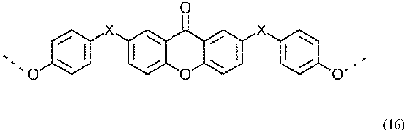
Darüber hinaus sind Polycarbonate bevorzugt, welche als Endgruppen Phenol tragen (Phenyl-terminiertes Polycarbonat).In addition, preference is given to polycarbonates which have phenol end groups (phenyl-terminated polycarbonate).
Um die Menge der Umlagerungsstrukturen zu bestimmen, wird das jeweilige Polycarbonat einer Totalverseifung unterzogen und so die entsprechenden Abbauprodukte der Formeln (13a) bis (16a) gebildet, deren Menge mit HPLC bestimmt wird (Dies kann z.B. wie folgt geschehen: Die Polycarbonatprobe wird mittels Natriummethylat unter Rückfluss verseift. Die entsprechende Lösung wird angesäuert und zur Trockne eingeengt. Der Trocknungsrückstand wird in Acetonitril gelöst und die phenolischen Verbindungen der Formel (1a) bis (4a) mittels HPLC mit UV-Detektion bestimmt):


Bevorzugt beträgt die Menge der dabei freigesetzten Verbindung der Formel (13a) 20 bis 800 ppm besonders bevorzugt 25 bis 700 ppm und insbesondere bevorzugt 30 bis 500 ppm.The amount of the compound of the formula (13a) released is preferably from 20 to 800 ppm, particularly preferably from 25 to 700 ppm and particularly preferably from 30 to 500 ppm.
Bevorzugt beträgt die Menge der dabei freigesetzten Verbindung der Formel (14a) 0 (d.h. unterhalb der Nachweisgrenze von 10 ppm) bis 100 ppm besonders bevorzugt 0 bis 80 ppm und insbesondere bevorzugt 0 bis 50 ppm.The amount of the compound of the formula (14a) released in the process is preferably from 0 (i.e. below the detection limit of 10 ppm) to 100 ppm, particularly preferably from 0 to 80 ppm and particularly preferably from 0 to 50 ppm.
Bevorzugt beträgt die Menge der dabei freigesetzten Verbindung der Formel (715a) 0 (d.h. unterhalb der Nachweisgrenze von 10 ppm) bis 800 ppm weiter bevorzugt 10 bis 700 ppm und besonders bevorzugt 20 bis 600 ppm sowie ganz besonders bevorzugt 30 bis 350 ppm.The amount of the compound of the formula (715a) released in the process is preferably 0 (i.e. below the detection limit of 10 ppm) to 800 ppm, more preferably 10 to 700 ppm and particularly preferably 20 to 600 ppm and very particularly preferably 30 to 350 ppm.
Bevorzugt beträgt die Menge der dabei freigesetzten Verbindung der Formel (16a) 0 (d.h. unterhalb der Nachweisgrenze von 10 ppm) bis 300 ppm bevorzugt 5 bis 250 ppm und insbesondere bevorzugt 10 bis 200 ppm.The amount of the compound of the formula (16a) released in the process is preferably from 0 (i.e. below the detection limit of 10 ppm) to 300 ppm, preferably from 5 to 250 ppm and particularly preferably from 10 to 200 ppm.
Die SiCoPCs weisen bevorzugt Natriumgehalte kleiner 200 ppb und insbesondere bevorzugt kleiner 150 ppb auf.The SiCoPCs preferably have sodium contents of less than 200 ppb and particularly preferably less than 150 ppb.
Den nach dem erfindungsgemäßen Verfahren erhältlichen Polysiloxan-Polycarbonat- Blockcokondensaten können Additive in Mengen von 0,0 Gew.-% bis 5,0 Gew.-%, bevorzugt 0,01 Gew.-% bis 1,00 Gew.-% zugemischt werden. Bei den Additiven handelt es sich um übliche Polymeradditive, wie z.B. die in
Diese Additive können einzeln oder in beliebigen Mischungen oder mehreren verschiedenen Mischungen der Polymerschmelze zugesetzt werden und zwar direkt bei der Isolierung des Polymeren (z.B. über ein Seitenaggregat wie Seitenextruder) Additive als reine Substanz oder als Masterbatch in Polycarbonat zugeführt werden. oder aber nach Aufschmelzung von Granulat in einem sogenannten Compoundierungsschritt. Dabei können die Additive beziehungsweise deren Mischungen als Feststoff, also als Pulver, oder als Schmelze der Polymerschmelze zugesetzt werden. Eine andere Art der Dosierung ist die Verwendung von Masterbatches oder Mischungen von Masterbatches der Additive oder Additivmischungen.These additives can be added to the polymer melt individually or in any desired mixtures or several different mixtures, specifically when the polymer is isolated (e.g. via a side unit such as a side extruder), additives as a pure substance or as a masterbatch in polycarbonate. or after melting granules in a so-called compounding step. The additives or mixtures thereof can be added to the polymer melt as a solid, that is to say as a powder, or as a melt. Another type of dosage is the use of masterbatches or mixtures of masterbatches of the additives or additive mixtures.
In einer bevorzugten Ausführungsform enthält die Polymerzusammensetzung Thermo- bzw. Verarbeitungsstabilisatoren wie sie auch in
Ferner können phenolische Antioxidantien wie alkylierte Monophenole, alkylierte Thioalkylphenole, Hydrochinone und alkylierte Hydrochinone eingesetzt werden. Besonders bevorzugt werden Irganox® 1010 (Pentaerythrit- 3-(4-hydroxy-3,5-di-tert-butylphenyl)propionat;
Geeignete UV-Absorber sind beispielsweise beschrieben in der
Besonders geeignete Ultraviolett-Absorber sind Hydroxy-Benzotriazole, wie 2-(3',5'-Bis-(1,1-dimethylbenzyl)-2'-hydroxy-phenyl)-benzotriazol (Tinuvin® 234, Ciba Spezialitätenchemie, Basel), 2-(2'-Hydroxy-5'-(tert.-octyl)-phenyl)-benzotriazol (Tinuvin® 329, Ciba Spezialitätenchemie, Basel), 2-(2'-Hydroxy-3'-(2-butyl)-5'-(tert.butyl)-phenyl)-benzotriazol (Tinuvin® 350, Ciba Spezialitätenchemie, Basel), Bis-(3-(2H-benztriazolyl)-2-hydroxy-5-tert.-octyl)methan, (Tinuvin® 360, Ciba Spezialitätenchemie, Basel), (2-(4,6-diphenyl-1,3,5-triazin-2-yl)-5-(hexyloxy)-phenol (Tinuvin® 1577, Ciba Spezialitätenchemie, Basel), sowie der Benzophenone 2,4-Dihydroxy-benzophenon (Chimasorb® 22 , Ciba Spezialitätenchemie, Basel) und 2-Hydroxy-4-(octyloxy)-benzophenon (Chimassorb® 81, Ciba, Basel), 2-Propenoic acid, 2-cyano-3,3-diphenyl-, 2,2-bis[[(2-cyano-1-oxo-3,3-diphenyl-2-propenyl)oxy]-methyl]-1,3-propanediyl ester (9CI) (Uvinul® 3030, BASF AG Ludwigshafen), 2-[2-hydroxy-4-(2-ethylhexyl)oxy]phenyl-4,6-di(4-phenyl)phenyl-1,3,5-triazine (CGX UVA 006, Ciba Spezialitätenchemie, Basel) oder Tetra-ethyl-2,2'-(1,4-phenylene-dimethylidene)-bismalonate (Hostavin® B-Cap, ClariantAG).Particularly suitable ultraviolet absorbers are hydroxy-benzotriazoles, such as 2- (3 ', 5'-bis- (1,1-dimethylbenzyl) -2'-hydroxyphenyl) -benzotriazole (Tinuvin® 234, Ciba Specialty Chemicals, Basel), 2- (2'-Hydroxy-5 '- (tert-octyl) -phenyl) -benzotriazole (Tinuvin® 329, Ciba Specialty Chemicals, Basel), 2- (2'-Hydroxy-3' - (2-butyl) - 5 '- (tert-butyl) -phenyl) -benzotriazole (Tinuvin® 350, Ciba Specialty Chemicals, Basel), bis- (3- (2H-benztriazolyl) -2-hydroxy-5-tert-octyl) methane, (Tinuvin ® 360, Ciba Specialty Chemicals, Basel), (2- (4,6-diphenyl-1,3,5-triazin-2-yl) -5- (hexyloxy) -phenol (Tinuvin® 1577, Ciba Specialty Chemicals, Basel), as well as the benzophenone 2,4-dihydroxy-benzophenone (Chimasorb® 22 , Ciba Specialty Chemicals, Basel) and 2-hydroxy-4- (octyloxy) -benzophenone (Chimassorb® 81, Ciba, Basel), 2-propenoic acid, 2-cyano-3,3-diphenyl-, 2,2-bis [ [(2-cyano-1-oxo-3,3-diphenyl-2-propenyl) oxy] methyl] -1,3-propanediyl ester (9CI) (Uvinul® 3030, BASF AG Ludwigshafen), 2- [2- hydroxy-4- (2-ethylhexyl) oxy] phenyl-4,6-di (4-phenyl) phenyl-1,3,5-triazine (CGX UVA 006, Ciba Specialty Chemicals, Basel) or tetra-ethyl-2,2 '- (1,4-phenylene-dimethylidene) -bismalonate (Hostavin® B-Cap, Clariant AG).
Es können auch Mischungen dieser Ultraviolett-Absorber eingesetzt werden.Mixtures of these ultraviolet absorbers can also be used.
Die erfindungsgemäßen Polymerzusammensetzungen können optional Entformungsmittel enthalten Besonders geeignete Entformungsmittel sind Pentaerythrittetrastearat (PETS) oder Glycerinmonostearat (GMS) oder Mischungen hieraus.The polymer compositions according to the invention can optionally contain mold release agents. Particularly suitable mold release agents are pentaerythritol tetrastearate (PETS) or glycerol monostearate (GMS) or mixtures thereof.
Weiterhin können den erfindungsgemäß Blockcokondensaten auch andere Polymere zugemischt werden, wie beispielsweise Polyestercarbonat, Polystyrol, Styrol-Copolymere, aromatische Polyester wie Polyethylenterephthalat (PET), PET-Cyclohexandimethanol-Copolymer (PETG), Polyethylennaphthalat (PEN), Polybutylenterephthalat (PBT), cyclisches Polyolefin, Poly- oder Poly- oder Copolyacrylate und Poly- oder Copolymethacrylat wie z.B. Poly- oder Copolymethylmethacrylate (wie PMMA) sowie Copolymere mit Styrol wie z.B. transparentes Polystyrolacrylnitril (PSAN), thermoplastische Polyurethane, Polymere auf Basis von zyklischen Olefinen (z.B. TOPAS®, ein Handelsprodukt der Firma Ticona).Furthermore, other polymers can also be added to the block cocondensates according to the invention, such as polyester carbonate, polystyrene, styrene copolymers, aromatic polyesters such as polyethylene terephthalate (PET), PET-cyclohexanedimethanol copolymer (PETG), polyethylene naphthalate (PEN), polybutylene terephthalate (PBT), cyclic polyolefin , Poly or poly or copolyacrylates and poly or copolymethacrylates such as poly or copolymethyl methacrylates (such as PMMA) and copolymers with styrene such as transparent polystyrene acrylonitrile (PSAN), thermoplastic polyurethanes, polymers based on cyclic olefins (e.g. TOPAS®, a Commercial product from Ticona).
Gegenstand der Erfindung ist ferner ein Verfahren zur Herstellung des erfindungsgemäßen Faserverbundwerkstoffes bzw. des Mehrschichtverbundwerkstoffs sowie ein Verfahren zur Herstellung eines Bauteils erhältlich aus einem Mehrschichtverbundwerkstoff, sowie die Verwendung des Mehrschichtverbundwerkstoffes zur Herstellung eines Gehäuses für z.B. ein elektronisches Gerät oder als Bauteil in Automotive Anwendungen sowie das daraus erhältliche Bauteil oder Gehäuse.The invention also relates to a method for producing the fiber composite material according to the invention or the multilayer composite material and a method for producing a component obtainable from a multilayer composite material, as well as the use of the multilayer composite material for the production of a housing for e.g. an electronic device or as a component in automotive applications as well as the component or housing available from it.
Herstellung der Faserverbundwerkstoffe und der Mehrschichtverbundwerkstoffe:Die Faserverbundwerkstofflagen des erfindungsgemäßen Mehrschichtverbundwerkstoffs können mit den üblichen dem Fachmann bekannten Verfahren zur Herstellung von Faserverbundwerkstoffen hergestellt werden. Production of the fiber composite materials and the multilayer composite materials: The fiber composite material layers of the multilayer composite material according to the invention can be produced with the usual methods known to the person skilled in the art for producing fiber composite materials.
Für die Herstellung der erfindungsgemäßen Faserverbundwerkstoffen bzw. Mehrschicht verbundwerkstoffen können verschiedene Herstellungsmethoden eingesetzt werden. Dabei kann zunächst grundlegend unterschieden werden, ob das der Faserverbundwerkstoff bzw. das Composite Sheet zum Beispiel aus unidirektionalen Faserlagen, Gewebelagen, Wirrfaserlagen oder aus Kombinationen daraus besteht, wobei unidirektionale Fasern entweder in Form eines Halbzeugs (z.B. Gelege) oder direkt als reiner Faserstrang in das Composite Sheet eingebracht werden kann. Bei letzterem Ansatz werden die Faserstränge in der Regel zunächst einlagig mit dem thermoplastischen Harz imprägniert (dem Faserverbundwerkstoff), um anschließend zu einem mehrlagigen System (Laminat) , dem Mehrschichtverbundwerkstoff, verpresst zu werden, wobei es hier verschiedene Methoden der Imprägnierung gibt. Sofern das Composite Sheet aus Faserhalbzeugen (Gewebe, Gelege, Wirrfaser etc.) herstellt wird, zeigt der Stand der Technik ebenfalls verschiedene Möglichkeiten auf, wie Faser und Matrix zusammengebracht werden können. Gängige Methoden sind zum Bespiel das Verfahren mithilfe von Pulver Prepregs oder das so genannte Film Stacking Verfahren. Das Film Stacking Verfahren kann bevorzugt für die Herstellung der zuvor beschriebenen Faserverbundwerkstoffe eingesetzt werden. Hierbei werden abwechselnd Folien und Gewebelagen aufeinander geschichtet, wobei Flächengewicht des Gewebes und Dicke der Folien beispielsweise so abgestimmt sein können, dass man einen gewünschten Faservolumengehalt erhält.Various production methods can be used for the production of the fiber composite materials or multilayer composite materials according to the invention. First of all, a fundamental distinction can be made as to whether the fiber composite material or the composite sheet consists, for example, of unidirectional fiber layers, fabric layers, random fiber layers or a combination thereof, with unidirectional fibers either in the form of a semi-finished product (e.g. scrim) or directly as a pure fiber strand in the Composite sheet can be introduced. In the latter approach, the Fiber strands are usually first impregnated in one layer with the thermoplastic resin (the fiber composite material) in order to then be pressed into a multi-layer system (laminate), the multi-layer composite material, whereby there are various methods of impregnation. If the composite sheet is made from semi-finished fiber products (woven fabric, scrim, random fiber, etc.), the state of the art also shows various ways in which fiber and matrix can be brought together. Common methods are, for example, the process using powder prepregs or the so-called film stacking process. The film stacking process can preferably be used for the production of the fiber composite materials described above. Here, films and fabric layers are alternately layered on top of one another, the weight per unit area of the fabric and the thickness of the films being able to be coordinated, for example, in such a way that a desired fiber volume content is obtained.
Gemäß einer bevorzugten Ausführungsform der Erfindung sind die Faserverbundwerkstofflagen des Mehrschichtverbundwerkstoffs herstellbar durch Auftragen eines geschmolzenen auf Polycarbonat basierenden Kunststoffs auf ein über die Glasübergangstemperatur des Kunststoffs vorgeheiztes Endlos-Faserband unter Druck-Scher-Vibrationsbeaufschlagung. Ein derartiges Herstellungsverfahren ist in
Unter einem Endlos-Faserband wird erfindungsgemäß eine Mehrzahl von zusammengeführten Rovings verstanden, wobei es sich bei den Rovings um Bündel aus vielen Endlosfasern-ohne Drall handelt.According to the invention, an endless fiber band is understood to mean a plurality of rovings brought together, the rovings being bundles of many endless fibers without twist.
Das bevorzugte Verfahren zur Herstellung einer Faserverbundwerkstofflage des Mehrschichtverbundwerkstoffs umfasst insbesondere die folgenden Schritte:
- Bereitstellen eines Endlos-Faserbandes und Fördern des Endlos-Faserbandes längs eines Bearbeitungsweges,
- Vorheizen des Endlos-Faserbandes auf eine Bearbeitungstemperatur, die höher ist als die Glasübergangstemperatur des auf Polycarbonat basierenden Kunststoffs,
- Auftragen des geschmolzenen auf Polycarbonat basierenden Kunststoffs auf einer gesamten Breite des Endlos-Faserbandes auf einer Oberfläche des Endlos-Faserbandes,
- Aufbringen eines Drucks auf das Endlos-Faserband senkrecht zur Bandebene nach dem Auftragen des auf Polycarbonat basierenden Kunststoffs, wobei das Druckaufbringen mit mindestens einem Druckstempel bei gleichzeitiger Scher-Vibrationsbeaufschlagung des Druckstempels mit einer Vibrations-Bewegungskomponente in der Bandebene und quer zu einer Band-Laufrichtung erfolgt,
- Halten des Endlos-Faserbandes innerhalb eines Bearbeitungstemperaturbereiches oberhalb der Glasübergangstemperatur des auf Polycarbonat basierenden Kunststoffs mindestens bis nach Abschluss der Druck-Scher-Vibrationsbeaufschlagung.
- Providing an endless sliver and conveying the endless sliver along a processing path,
- Preheating the continuous fiber band to a processing temperature that is higher than the glass transition temperature of the polycarbonate-based plastic,
- Applying the molten polycarbonate-based plastic over an entire width of the endless fiber band on a surface of the endless fiber band,
- Applying a pressure to the endless fiber band perpendicular to the band plane after the application of the polycarbonate-based plastic, the pressure being applied with at least one pressure stamp with simultaneous shear vibration loading of the pressure stamp with a vibration movement component in the band plane and transversely to a band running direction ,
- Maintaining the endless fiber band within a processing temperature range above the glass transition temperature of the polycarbonate-based plastic at least until after the pressure-shear-vibration application is complete.
Ein Schmelzauftrag mit nachfolgender Druck-Scher-Vibrationsbeaufschlagung, solange das Roh-Faserband eine Temperatur oberhalb der Glasübergangstemperatur des auf Polycarbonat basierenden Kunststoffs hat, führt zu einem wirksamen Einarbeiten der Kunststoffschmelze in die gesamte Faser-Volumenstruktur des Roh-Faserbandes. Bevorzugt wird eine Temperatur des Endlos-Faserbandes von 380°C nicht überschritten. Üblicherweise beträgt die Temperatur des Endlosfaserbandes zwischen 180°C bis 260°C, bevorzugt zwischen 200°C bis 240°C, besonders bevorzugt zwischen 210°C bis 230°C, insbesondere 220°C. Wenn hier von Erhitzen über die Glasübergangstemperatur des Kunststoffs oder Halten über der Glasübergangstemperatur des Kunststoffs die Rede ist, so ist damit das Erhitzen auf eine Temperatur gemeint, bei der der Kunststoff vollständig geschmolzen vorliegt. Die Glasübergangstemperatur des Kunststoffs kann mittels DIN EN ISO 17025 bestimmt werden. Eine Differenz zwischen der Fasertemperatur und der Schmelzetemperatur beim Zusammentreffen der Kunststoffschmelze mit dem Endlos-Faserband liegt im Bereich von 60°C bis 120°C, bevorzugt von 70°C bis 110°C, besonders bevorzugt von 80°C bis 100°C. Durch die Druck-Scher-Vibrationsbeaufschlagung werden Gasvolumina, die sich noch innerhalb des Roh-Faserbandes befinden, effizient ausgetrieben. Das Verfahren kann kontinuierlich durchgeführt werden. Das Halten des Endlos-Faserbandes auf einer Temperatur oberhalb der Glasübergangstemperatur des Kunststoffs stellt sicher, dass der auf Polycarbonat basierende Kunststoff nicht unerwünscht vor dem vollständigen Eindringen und Teilen innerhalb und auf dem Endlos-Faserband erstarrt. Dieses Beibehalten einer Temperatur oberhalb der Glasübergangstemperatur des Kunststoffs kann nach Abschluss der Druck-Scher-Vibrationsbeaufschlagung noch während eines Beruhigungsintervalls fortgesetzt werden. Nach dem Durchführen der angegebenen Verfahrensschritte kann das hergestellte, imprägnierte Endlos-Faserband definiert abgekühlt werden. Das Endlos-Faserband kann eine Vielzahl von Endlos-Fasern aufweisen. Aufgrund der Druck-Scher-Vibrationsbeaufschlagung kann eine geringe bis nicht vorhandene Schädigung der Fasern bei guter Kunststoffdurchdringung des Faserbandes, also bei guter Imprägnierung, realisiert werden.A melt application with subsequent pressure-shear-vibration application, as long as the raw sliver has a temperature above the glass transition temperature of the polycarbonate-based plastic, leads to an effective incorporation of the plastic melt into the entire fiber volume structure of the raw sliver. A temperature of the endless sliver of 380 ° C. is preferably not exceeded. The temperature of the continuous fiber band is usually between 180.degree. C. to 260.degree. C., preferably between 200.degree. C. to 240.degree. C., particularly preferably between 210.degree. C. to 230.degree. C., in particular 220.degree. If heating above the glass transition temperature of the plastic or holding above the glass transition temperature of the plastic is mentioned, this means heating to a temperature at which the plastic is completely melted. The glass transition temperature of the plastic can be determined using DIN EN ISO 17025. A difference between the fiber temperature and the melt temperature when the plastic melt meets the endless fiber band is in the range from 60 ° C to 120 ° C, preferably from 70 ° C to 110 ° C, particularly preferably from 80 ° C to 100 ° C. By applying pressure-shear-vibration, gas volumes that are still within the raw fiber sliver are efficiently expelled. The process can be carried out continuously. Maintaining the continuous fiber band at a temperature above the glass transition temperature of the plastic ensures that the polycarbonate-based plastic does not solidify undesirably before it completely penetrates and splits within and on the continuous fiber band. This maintenance of a temperature above the glass transition temperature of the plastic can be continued during a calming interval after the pressure-shear-vibration application has ended. After the specified process steps have been carried out, the impregnated endless fiber sliver produced can be cooled in a defined manner. The endless fiber band can have a multiplicity of endless fibers. Due to the application of pressure-shear-vibration, little or no damage to the fibers can be achieved with good plastic penetration of the fiber band, that is, with good impregnation.
Besonders bevorzugt wird das Verfahren zur Herstellung einer Faserverbundwerkstofflage des Mehrschichtverbundwerkstoffs so geführt, dass das Auftragen des auf Polycarbonat basierenden Kunststoffs auf das Endlos-Faserband erfolgt, während das Endlos-Faserband unter Normal-Umgebungsdruck gefördert wird. Ein solches Auftragen des Kunststoffs vermeidet eine aufwändige Abdichtung einer unter Druck stehenden Auftragskammer nach außen.The method for producing a fiber composite material layer of the multilayer composite material is particularly preferably carried out in such a way that the polycarbonate-based plastic is applied to the endless fiber band while the endless fiber band is conveyed under normal ambient pressure. Such an application of the plastic avoids a complex sealing of a pressurized application chamber from the outside.
Es ist ferner bevorzugt, das Verfahren zur Herstellung einer Faserverbundwerkstofflage des Mehrschichtverbundwerkstoffs so zu führen, dass die Druck-Scher-Vibrations-beaufschlagung eines Abschnitts des Endlos-Faserbandes nach dem Kunststoffauftrag mehrmals hintereinander längs des Bearbeitungsweges erfolgt. Es ist auch möglich das Verfahren so zu führen, dass die Druck-Scher-Vibrationsbeaufschlagung eines Abschnitts des Endlos-Faserbandes nach dem Kunststoffauftrag von beiden Seiten der Bandebene her erfolgt. Eine mehrfache Druck-Scher-Vibrationsbeaufschlagung erhöht die Effizienz des Herstellungsverfahrens. Quer-Bewegungskomponenten der verschiedenen Druck-Scher-Vibrationsbeaufschlagungseinrichtungen können synchronisiert gegenläufig, also im Gegentakt, gesteuert werden. Zwischen den hintereinander erfolgenden Druck-Scher-Vibrationsbeaufschlagungen kann gezielt jeweils ein Beruhigungsintervall vorgesehen sein, bei dem das Roh-Faserband während einer vorgegebenen Zeitspanne nicht mit Druck und/oder Scher-Vibration beaufschlagt ist. Eine Druck-Scher-Vibrationsbeaufschlagung von beiden Seiten her kann durch Druckbeaufschlagungseinrichtungen erfolgen, die im Bearbeitungsweg nacheinander angeordnet sind. Alternativ ist eine gleichzeitige Druck-Scher-Vibrationsbeaufschlagung von beiden Seiten her möglich. Auch die Druck-Scher-Vibrationsbeaufschlagung von beiden Seiten her kann mit einer synchronisierten Gegenläufigkeit der Quer-Bewegungskomponenten, also im gesteuerten Gegentakt, erfolgen.It is also preferred to carry out the method for producing a fiber composite layer of the multilayer composite material in such a way that the pressure-shear-vibration loading of a section of the endless fiber band occurs several times in succession along the processing path after the plastic has been applied. It is also possible to carry out the method in such a way that the pressure-shear-vibration application of a section of the endless fiber band occurs from both sides of the band plane after the plastic has been applied. A multiple pressure-shear-vibration application increases the efficiency of the manufacturing process. Transverse movement components of the various pressure-shear-vibration loading devices can be synchronized in opposite directions, that is, controlled in push-pull. Between the successive pressure-shear-vibration applications, a calming interval can be provided in each case, in which the raw fiber sliver is not subjected to pressure and / or shear-vibration during a predetermined period of time. A pressure-shear-vibration application from both sides can take place by means of pressure application devices which are arranged one after the other in the processing path. Alternatively, a simultaneous pressure-shear-vibration application from both sides is possible. The pressure-shear-vibration application from both sides can also take place with a synchronized counter-rotation of the transverse movement components, i.e. in controlled push-pull.
Die Frequenzen der Druck-Scher-Vibrationsbeaufschlagung können im Bereich zwischen 1 Hz und 40 kHz liegen. Amplituden der Scher-Vibrationsbeaufschlagung können im Bereich zwischen 0,1 mm und 5 mm liegen. Ein Druck der Druck-Scher-Vibrationsbeaufschlagung kann im Bereich zwischen 0,01 MPa und 2 MPa liegen.The frequencies of the pressure-shear-vibration application can be in the range between 1 Hz and 40 kHz. The amplitudes of the shear vibration application can be in the range between 0.1 mm and 5 mm. A pressure of the pressure-shear vibration application can be in the range between 0.01 MPa and 2 MPa.
Unter dem Verbinden der geschichteten Lagen Faserverbundwerkstoff wird erfindungsgemäß jedes Verfahren verstanden, welches eine körperliche Verbindung der geschichteten Lagen Faserverbundwerkstoff zur Folge hat. Vorzugsweise erfolgt das Verbinden der geschichteten Lagen Faserverbundwerkstoff zum Mehrschichtverbundwerkstoff mittels Druck und/oder Temperatur, z.B. durch Laminierung. Der zum Verbinden der geschichteten Lagen Faserverbundwerkstoff zum Mehrschichtverbundwerkstoff eingesetzte Druck kann im Bereich von 5 bis 15 bar, bevorzugt 7 bis 13 bar, besonders bevorzugt 8 bis 12 bar liegen. Die Temperatur zum Verbinden der Faserverbundwerkstofflagen kann 80°C bis 300°C betragen. Wird ein Verbindungsverfahren mit Heiz- und Kühlzonen angewendet, so kann die Temperatur zum Verbinden der Faserverbundwerkstofflagen in den Heizzonen von 220°C bis 300°C, bevorzugt von 230°C bis 290°C, besonders bevorzugt von 240°C bis 280°C, betragen. Die Temperatur in den Kühlzonen kann von 80°C bis 140°C, bevorzugt von 90°C bis 130°C, besonders bevorzugt von 100°C bis 120°C, betragen.According to the invention, connecting the layered layers of fiber composite material is understood to mean any method which results in a physical connection of the layered layers of fiber composite material. The layered layers of fiber composite material are preferably connected to form the multilayer composite material by means of pressure and / or temperature, for example by lamination. The pressure used to connect the layered layers of fiber composite material to the multilayer composite material can be in the range from 5 to 15 bar, preferably 7 to 13 bar, particularly preferably 8 to 12 bar. The temperature for connecting the fiber composite layers can be 80 ° C to 300 ° C. If a joining process with heating and cooling zones is used, the temperature for joining the fiber composite layers in the heating zones can be from 220 ° C to 300 ° C, preferably from 230 ° C to 290 ° C, particularly preferably from 240 ° C to 280 ° C , amount. The temperature in the cooling zones can be from 80.degree. C. to 140.degree. C., preferably from 90.degree. C. to 130.degree. C., particularly preferably from 100.degree. C. to 120.degree.
Neben dem Laminieren sind jedoch auch beispielsweise Kleben oder Schweißen zum Verbinden der geschichteten Lagen Faserverbundwerkstoff möglichIn addition to lamination, however, gluing or welding, for example, to connect the layered layers of fiber composite material are also possible
Gemäß einer bevorzugten Ausführungsform resultiert das Verbinden der geschichteten Lagen Faserverbundwerkstoff in flächig miteinander verbundenen Lagen Faserverbundwerkstoff. Flächig bedeutet dabei, dass mindestens 50 %, vorzugsweise mindestens 75 %, 90 %, 95 %, 99 % oder 100 % ("vollflächige" Verbindung) der einander zugewandten Oberflächen zweier benachbarter Lagen Faserverbundwerkstoff miteinander unmittelbar verbunden sind. Der Grad der Verbindung kann mikroskopisch in Querschnitten bestimmt werden oder auch durch die Abwesenheit von Hohlräumen, z.B. Lufteinschlüssen, im Faserverbundwerkstoff bestimmt werden.According to a preferred embodiment, the connection of the layered layers of fiber composite material results in layers of fiber composite material that are flatly connected to one another. Flat means that at least 50%, preferably at least 75%, 90%, 95%, 99% or 100% ("full-area" connection) of the mutually facing surfaces of two adjacent layers of fiber composite are directly connected to one another. The degree of connection can be determined microscopically in cross-sections or it can be determined by the absence of cavities, e.g. air inclusions, in the fiber composite material.
Mehrschichtverbundwerkstoffe lassen sich weiterhin auch über eine statische Presse herstellen. Dabei werden Folien aus SiCoPC und die Gewebelagen abwechselnd geschichtet, wobei die äußeren Lagen jeweils durch eine Folienlage abgeschlossen werden.Multi-layer composite materials can still be produced using a static press. Films made of SiCoPC and the fabric layers are alternately layered, with the outer layers each being closed off by a film layer.
Ein weiterer Vorteil des erfindungsgemäßen Mehrschichtverbundwerkstoffs ist, dass er in beliebige Formen umgeformt werden kann. Zur Umformung können alle dem Fachmann bekannten Umformungsverfahren eingesetzt werden. Solche Umformungsverfahren können unter Druck- und/oder Wärmeeinwirkung erfolgen.Another advantage of the multilayer composite material according to the invention is that it can be reshaped into any shape. For the deformation, all deformation processes known to the person skilled in the art can be used. Such forming processes can take place under the action of pressure and / or heat.
Gemäß einer Ausführungsform des erfindungsgemäßen Verfahrens erfolgt die Umformung unter Wärmeeinwirkung, insbesondere durch Thermoverformung.According to one embodiment of the method according to the invention, the deformation takes place under the action of heat, in particular by thermoforming.
Um eine bessere Verträglichkeit der Faserlagen und insbesondere der Endlosfasern mit dem thermoplastischen Matrixmaterialien zu erhalten, können die Faserlagen, insbesondere die Endlosfasern oder Gewebe / Gewirke, mit einer Silanverbindung an ihrer Oberfläche vorbehandelt sein. Bevorzugte Silanverbindungen sind Aminopropyltrimethoxysilan, Aminobutyltrimethoxysilan, Aminopropyltriethoxysilan, AminobutyltriethoxysilanIn order to obtain better compatibility of the fiber layers and in particular the continuous fibers with the thermoplastic matrix materials, the fiber layers, in particular the continuous fibers or woven / knitted fabrics, can be pretreated with a silane compound on their surface. Preferred silane compounds are aminopropyltrimethoxysilane, aminobutyltrimethoxysilane, aminopropyltriethoxysilane, and aminobutyltriethoxysilane
Generell lassen sich die Fasern über Schlichten derart chemisch und/oder physikalisch modifizieren, um beispielsweise bei der anschließenden Herstellung von Faserverbundwerkstoffen aus den Faserlagen und dem Matrixmaterial den gewünschten Grad der Anbindung zwischen Fasern und dem Matrixmaterial einzustellen. Hierzu können alle dem Fachmann bekannten Schlichten eingesetzt werden, und zwar neben den oben genannten Silanverbindungen bevorzugt Epoxidharze und deren Derivate, Epoxyester, Epoxyether, Epoxyurethane, Polyurethanester, Polyurethanether, Isocyanate, Polyimide, Polyamide und beliebige Mischungen aus zwei oder mehr der vorstehenden Verbindungen. Die konkrete Auswahl des Schlichtematerials hängt von dem Material der Fasern und der gewünschten Stärke der Anbindung ab. Dabei kann die Schlichte beispielsweise in Form einer wässrigen oder nicht-wässrigen Lösung oder Emulsion eingesetzt werden, wobei die Anbringung der Schlichte an die erfindungsgemäßen Fasern dabei nach bekannten Verfahren für die Beschlichtung von Kurzfasern, beispielsweise in einem Tauchprozess, erfolgen kann.In general, the fibers can be chemically and / or physically modified by means of sizes in order, for example, to set the desired degree of connection between fibers and the matrix material in the subsequent production of fiber composite materials from the fiber layers and the matrix material. For this purpose, all sizes known to the person skilled in the art can be used, specifically in addition to the abovementioned silane compounds, preferably epoxy resins and their derivatives, epoxy esters, epoxy ethers, epoxy urethanes, polyurethane esters, polyurethane ethers, isocyanates, polyimides, polyamides and any mixtures of two or more of the above compounds. The specific selection of the Sizing material depends on the material of the fibers and the desired strength of the connection. The size can be used, for example, in the form of an aqueous or non-aqueous solution or emulsion, it being possible for the size to be applied to the fibers according to the invention by known methods for sizing short fibers, for example in a dipping process.
Wesentlicher Aspekt ist die Tatsache, dass das strukturversteifende Fasermaterial und das thermoplastische Material eine stoffschlüssige Verbindung miteinander eingehen. Die Einstellung der stoffschlüssigen Verbindung erfolgt über die Prozessparameter, insbesondere Massetemperatur und Werkzeugtemperatur sowie Druck und hängt auch von der oben erwähnten Schlichte ab.The essential aspect is the fact that the structure-stiffening fiber material and the thermoplastic material enter into a cohesive bond with one another. The setting of the cohesive connection takes place via the process parameters, in particular melt temperature and mold temperature as well as pressure and also depends on the size mentioned above.
Ein weiterer Gegenstand der Erfindung ist ein Gehäuseteil, welches geeignet ist für die Verwendung als oder den Einsatz in einem Gehäuse eines elektronischen Geräts, wobei das Gehäuseteil einen erfindungsgemäßen Mehrschichtverbundwerkstoff enthält oder nach dem erfindungsgemäßen Verfahren zur Herstellung eines Gehäuseteils erhältlich ist und wobei das Gehäuse eines elektronischen Geräts vorzugsweise die Monitorrückseite oder die Unterseite eines Laptops darstellt.Another object of the invention is a housing part which is suitable for use as or in a housing of an electronic device, the housing part containing a multilayer composite material according to the invention or being obtainable by the method according to the invention for producing a housing part and wherein the housing of an electronic Device preferably represents the back of the monitor or the underside of a laptop.
Gehäuseteile erhältlich aus den erfindungsgemäßen Verbundwerkstoffen werden insbesondere im IT Bereich verwendet als Gehäuseteile von beispielsweise Computern, Monitoren, Tablets oder Telefonen, Beispielsweise kann ein Gehäuseteil die Rückseite eines Mobiltelefons, die Unterseite eines Laptops, die Monitorrückseite eines Laptops, die Rückseite eines Tablets, etc. darstellen oder aber auch nur Bestandteil einer Rückseite eines Mobiltelefons, einer Unterseite eines Laptops, einer Monitorrückseite eines Laptops, einer Rückseite eines Tablets, etc. sein.Housing parts obtainable from the composite materials according to the invention are used in particular in the IT sector as housing parts for computers, monitors, tablets or telephones, for example. represent or only be part of a back of a mobile phone, a bottom of a laptop, a monitor back of a laptop, a back of a tablet, etc.
Gegenstand der Erfindung sind weiterhin Bauteile bzw. Struktur- und Kleidungselemente des Fahrzeuginnenbereichs (Wände, Deckenverkleidungen, Türen, Fenster etc.), Gepäckablagen, Führerpult, Tische, Schall- und Dämmstoffe, vertikale Oberflächen der Fahrzeugaußenhaut, Außenflächen des Unterbaus, Leuchtenabdeckungen, Lichtdiffuser etc. wobei das Teil bzw. Struktur- und Kleidungselement einen erfindungsgemäßen Mehrschichtverbundwerkstoff enthält. Faserverbundwerkstoffe der vorliegenden Erfindung können weiterhin verwendet werden zur Herstellung von dünnwandigen Formteilen (z.B. Datentechnik-Gehäuseteile, TV-Gehäuse, Notebooks), wo besonders hohe Ansprüche an Kerbschlagzähigkeit, Fließnahtfestigkeit, Flammwidrigkeit und Oberflächenqualität der eingesetzten Materialien gestellt werden, weiterhin zur Herstellung von Gehäuseteilen z.B. für Haushaltsgeräte, Büromaschinen, wie Monitore oder Drucker, oder Abdeckplatten für den Bausektor und Teile für den Kfz-Sektor oder Teile für den Elektrosektor, die ebenfalls Gegestand der vorliegenden Erfindung sind.The invention also relates to components or structural and clothing elements of the vehicle interior (walls, ceiling cladding, doors, windows, etc.), luggage racks, driver's desk, tables, sound and insulation materials, vertical surfaces of the vehicle outer skin, outer surfaces of the substructure, light covers, light diffusers, etc. The part or structural and clothing element containing a multilayer composite material according to the invention. Fiber composite materials of the present invention can also be used for the production of thin-walled molded parts (e.g. data technology housing parts, TV housings, notebooks), where particularly high demands are placed on notched impact strength, weld seam strength, flame resistance and surface quality of the materials used, furthermore for the production of housing parts, e.g. for household appliances, office machines, such as monitors or printers, or cover plates for the building sector and parts for the motor vehicle sector or parts for the electrical sector, which are also the subject of the present invention.
Weitere Einzelheiten und Vorteile der Erfindung ergeben sich aus der nachfolgenden Beschreibung der zugehörigen Zeichnung, die bevorzugte Ausführungsformen zeigt. In der Zeichnung zeigen:
- Fig. 1
- einen Mehrschichtverbundwerkstoff in schematischer und perspektivischer Darstellung aus drei übereinanderliegenden Lagen Faserverbundwerkstoff mit Ausschnittsvergrößerung, wobei die innenliegende Lage relativ zu den außenliegenden Lagen Faserverbundwerkstoff um 90° rotiert ist,
- Fig. 2
- einen Mehrschichtverbundwerkstoff in schematischer und perspektivischer Darstellung aus fünf übereinanderliegenden Lagen Faserverbundwerkstoff, wobei die innenliegenden Lagen gleich orientiert sind und ihre Orientierung relativ zu den außenliegenden Lagen Faserverbundwerkstoff um 90° rotiert sind,
- Fig. 3a
- einen Mehrschichtverbundwerkstoff in schematischer und perspektivischer Darstellung aus sechs übereinanderliegenden Lagen Faserverbundwerkstoff, wobei die innenliegenden Lagen gleich orientiert sind und ihre Orientierung relativ zu den außenliegenden Lagen Faserverbundwerkstoff um 90° rotiert sind,
- Fig. 3b:
- einen Mehrschichtverbundwerkstoff in schematischer und perspektivischer Darstellung aus drei übereinanderliegenden Lagen Faserverbundwerkstoff, wobei die innenliegende Lage eine höhere Dicke aufweist als die Summe der beiden außenliegenden Lagen. Das Dickenverhältnis der innenliegenden Lage zur Summe der beiden außenliegenden Lagen entspricht dabei dem Dickenverhältnis der Summe aller innenliegenden Lagen zur Summe der beiden außenliegenden Lagen des Mehrschichtverbundwerkstoffs aus
Fig. 3a , - Fig. 4a
- einen Mehrschichtverbundwerkstoff in schematischer und perspektivischer Darstellung aus drei übereinanderliegenden Lagen Faserverbundwerkstoff und einer zusätzlichen Materiallage auf einer außenliegenden Lage Faserverbundwerkstoff,
- Fig. 4b
- einen Mehrschichtverbundwerkstoffs in schematischer und perspektivischer Darstellung aus drei übereinanderliegenden Lagen Faserverbundwerkstoff und zwei zusätzlichen innenliegenden weiteren Materiallagen, beispielsweise Kunststoffschichten, wobei sich jeweils eine innenliegende weitere Materiallage zwischen den außenliegenden Lagen Faserverbundwerkstoff und der innenliegenden Lage Faserverbundwerkstoff befindet, und
- Fig. 1
- a multi-layer composite material in a schematic and perspective representation of three superimposed layers of fiber composite material with an enlarged section, the inner layer being rotated by 90 ° relative to the outer layers of fiber composite material,
- Fig. 2
- a multi-layer composite material in a schematic and perspective representation of five superimposed layers of fiber composite material, the inner layers are oriented in the same way and their orientation relative to the outer layers of fiber composite material is rotated by 90 °,
- Fig. 3a
- a multi-layer composite material in a schematic and perspective representation of six layers of fiber composite material lying one on top of the other, the inner layers being oriented in the same way and their orientation being rotated by 90 ° relative to the outer layers of fiber composite material,
- Fig. 3b:
- a multi-layer composite material in a schematic and perspective representation of three superimposed layers of fiber composite material, the inner layer having a greater thickness than the sum of the two outer layers. The thickness ratio of the inner layer to the sum of the two outer layers corresponds to the thickness ratio of the sum of all inner layers to the sum of the two outer layers of the multilayer composite material
Fig. 3a , - Figure 4a
- a multi-layer composite material in a schematic and perspective representation of three layers of fiber composite material lying on top of one another and an additional material layer on an outer layer of fiber composite material,
- Figure 4b
- a multilayer composite material in a schematic and perspective representation of three superimposed layers of fiber composite material and two additional inner layers of material, for example plastic layers, with an inner further material layer between the outer layers of fiber composite material and the inner layer of fiber composite material, and
Der Mehrschichtverbundwerkstoff 1 gemäß
Der Mehrschichtverbundwerkstoff 1 gemäß
Im Folgenden wird die Erfindung anhand von Ausführungsbeispielen näher beschrieben, wobei die hier beschriebenen Bestimmungsmethoden für alle korrespondierenden Größen in der vorliegenden Erfindung zur Anwendung kommen, sofern nichts Gegenteiliges beschrieben worden ist.The invention is described in more detail below with the aid of exemplary embodiments, the determination methods described here being used for all corresponding variables in the present invention, unless otherwise described.
Als Ausgangsstoff für die Reaktivextrusion wird lineares Bisphenol-A-Polycarbonat mit Endgruppen basierend auf Phenol mit einem Schmelzvolumenindex von 59 ― 62 cm3/10min (gemessen bei 300 °C und 1,2 kg Belastung gemäß ISO 1133 (Jahr 2011)) eingesetzt. Dieses Polycarbonat enthält keine Additive wie UV-Stabilisatoren, Entformungsmittel oder Thermostabilisatoren. Die Darstellung des Polycarbonats erfolgte über einen Schmelzeumesterungsprozess wie in
Hydrochinon-terminiertes Polydimethylsiloxan der Formel (11) mit n von ca. 20 und m im Bereich von 3 bis 4 in Formel (2) (R1 = H, R2 = Methyl,) , mit einem Hydroxy-Gehalt von 22,2 mg KOH/g und einer Viskosität von 175 mPas (23°C); der Natrium-Gehalt beträgt ca. 3 ppm. Das Siloxan enthält ca. 3 Gew.% Isooktanol.

Als Katalysator wird Tetraphenylphosphoniumphenolat der Firma Rhein Chemie Rheinau GmbH (Mannheim Deutschland) in Form eines Masterbatches eingesetzt. Tetraphenylphosphoniumphenolat wird als Mischkristall mit Phenol eingesetzt und enthält ca. 70 % Tetraphenylphosphoniumphenolat. Die nachfolgenden Mengen beziehen sich auf die von der Firma Rhein Chemie erhaltene Substanz (als Mischkristall mit Phenol).The catalyst used is tetraphenylphosphonium phenolate from Rhein Chemie Rheinau GmbH (Mannheim Germany) in the form of a masterbatch. Tetraphenylphosphonium phenolate is used as a mixed crystal with phenol and contains approx. 70% tetraphenylphosphonium phenolate. the The following amounts relate to the substance obtained from Rhein Chemie (as mixed crystal with phenol).
Der Masterbatch wird als 0,25 %ige Mischung hergestellt. Hierzu werden 4982 g mit 18 g Tetraphenylphosphoniumphenolat im Rhönradmischer für 30 Minuten aufgetrudelt. Das Masterbatch wird im Verhältnis 1:10 dosiert, so dass in der Gesammenge an Polycarbonat der Katalysator mit einem Anteil von 0,025 Gew.-% vorliegt.The masterbatch is produced as a 0.25% mixture. For this purpose, 4982 g with 18 g of tetraphenylphosphonium phenolate are rolled up in a gymnastics wheel mixer for 30 minutes. The masterbatch is metered in at a ratio of 1:10, so that in the total amount of polycarbonate, the catalyst is present in a proportion of 0.025% by weight.
Die Bestimmung des Schmelzvolumenrate (MVR) erfolgt soweit nicht anders angegeben nach ISO 1133 (Jahr 2011) (bei 300 °C; 1,2 kg) soweit keine anderen Bedingungen beschrieben worden sind.Unless otherwise stated, the melt volume rate (MVR) is determined in accordance with ISO 1133 (year 2011) (at 300 ° C; 1.2 kg) unless other conditions have been described.
Bestimmung der Lösungsviskosität: Die relative Lösungsviskosität (ηrel; auch als eta rel bezeichnet) wurde in Dichlormethan bei einer Konzentration von 5 g/1 bei 25 °C mit einem Ubbelohdeviskosimeter bestimmt.Determination of the solution viscosity: The relative solution viscosity (ηrel; also referred to as eta rel) was determined in dichloromethane at a concentration of 5 g / 1 at 25 ° C. using an Ubbeloh viscometer.
Der Natriumgehalt wird über Massenspektroskopie mit induktiv gekoppeltem Plasma (ICP-MS) bestimmt.The sodium content is determined by mass spectroscopy with inductively coupled plasma (ICP-MS).
Die Herstellung des Blockcokondensats aus der Polycarbonat-Komponente und der Siloxan-Komponente erfolgt über ein Reaktivextrusionsverfahren gemäß
Bei dem Hochviskosreaktor handelt es sich um einen selbstreinigenden Apparat mit zwei gegenläufigen, horizontal und achsparallel angeordneten Rotoren. Der Aufbau ist in der
Das Blockcokondensat weist einen MVR von 6,3 cm3/10 min auf.The block cocondensate has an MVR of 6.3 cm3 / 10 min.
Das Blockcokondensat weist einen Natriumgehalt von 140 ppb auf.The block cocondensate has a sodium content of 140 ppb.
- Makrolon® 3108 (lineares Bisphenol A ―basiertes Polycarbonat) der Covestro Deutschland AG mit einem MVR von 6 cm3/10 min.Makrolon® 3108 (linear bisphenol A ―based polycarbonate) from Covestro Deutschland AG with an MVR of 6 cm3 / 10 min.
- Makrolon® 2608 (lineares Bisphenol A ―basiertes Polycarbonat) der Covestro Deutschland AG mit einem MVR von 12 cm3/10 min .Makrolon® 2608 (linear bisphenol A ―based polycarbonate) from Covestro Deutschland AG with an MVR of 12 cm3 / 10 min.
Das jeweilige Granulat wird für 4 Stunden bei 110 °C getrocknet und wird danach mittels eines Einschneckenextruders (Kuhne (Typ: K35-24D) Drehzahl Extruder 40 U/min; Massetemperatur Extruder ca. 250°C) mit Breitschlitzdüse (Breitschlitzfoliendüse 450 mm; Lippenspalt 0,8 mm; Abzug Gießwalze 130°C; Abzug Kühlwalze 130°C; Abzugsgeschwindigkeit ca. 3 m/min) zu Folien der Dicke von ca. 130 µm verarbeitet. Diese Folien wurden anschließend im Film-Stacking Verfahren gemäß den unten genannten Prozessparametern auf einer statischen Presse vom Typ Organo Presse LAP 100 der Firma Gottfried Joos Maschinenfabrik GmbH zu Composite Sheets weiterverarbeitet. Zur Herstellung der Composite Sheets wurden Glasfasergewebe der Firma Schlösser & Cramer KG (Haan, Deutschland) vom Typ Style 3107 mit einem K506 Finish eingesetzt. Die Gewebe besitzen ein Flächengewicht von 390 g/m2 bei einer Köper 2/2 Bindung. Folien und Gewebelagen wurden abwechselnd geschichtet, wobei Ober- und Unterseite des Composite Sheets jeweils durch eine Folienlage abgeschlossen wurde. Insgesamt werden 5 Folien aus Substratmaterial mit 4 Glasfasergewebematten im Wechsel aufeinandergelegt, so dass die Kettrichtung gleich bleibt. Die Materialien werden bei konstantem Druck von 12 bar verpresst, wobei die Temperatur zwischen 280 und 295 °C liegt.The respective granulate is dried for 4 hours at 110 ° C and then by means of a single-screw extruder (Kuhne (type: K35-24D) extruder speed 40 rpm; extruder melt temperature approx. 250 ° C) with slot die (slot film die 450 mm; lip gap 0.8 mm; take-off casting roller 130 ° C; take-off cooling roller 130 ° C; take-off speed approx. 3 m / min) processed into foils with a thickness of approx. 130 µm. These foils were then further processed into composite sheets using the film stacking method according to the process parameters mentioned below on a static press of the Organo Presse LAP 100 type from Gottfried Joos Maschinenfabrik GmbH. To produce the composite sheets, glass fiber fabrics from Schlösser & Cramer KG (Haan, Germany) of the Style 3107 type with a K506 finish were used. The fabrics have a weight per unit area of 390 g / m 2 with a
Zur Herstellung des Mehrschichtverbundwerkstoffs wird Makrolon 2608 eingesetzt. Das Material wird wie oben beschrieben zu Folien extrudiert und zum Mehrschichtverbund weiterverarbeitet.Makrolon 2608 is used to manufacture the multilayer composite. The material is extruded into foils as described above and processed into a multi-layer composite.
Zur Herstellung des Mehrschichtverbundwerkstoffs wird Makrolon 3108 eingesetzt. Das Material wird wie oben beschrieben zu Folien extrudiert und zum Mehrschichtverbund weiterverarbeitet.Makrolon 3108 is used to manufacture the multilayer composite. The material is extruded into foils as described above and processed into a multi-layer composite.
Zur Herstellung des Mehrschichtverbundwerkstoffs wird Siloxan-haltiges Blockcokondensat verwendet, welches wie oben beschrieben hergestellt wurde,. Das Material wird wie oben beschrieben zu Folien extrudiert und zum Mehrschichtverbund weiterverarbeitet.To produce the multilayer composite material, siloxane-containing block cocondensate is used, which was produced as described above. The material is extruded into foils as described above and processed into a multi-layer composite.
Zur Herstellung des Mehrschichtverbundwerkstoffs wird Siloxan-haltiges Blockcokondensat verwendet, welches wie oben beschrieben hergestellt wurde,. Mittels Compoundierung wird diesem Siloxan-haltigem Blockcokondensatzur Einfärbung noch 1 % Titandioxid (Kronos 2230 der Firma Kronos Worldwide Inc.) und 0,2 % Lotader 8900 der Firma Arkema zugesetzt. Das Material weist einen MVR von 6,6 auf.To produce the multilayer composite material, siloxane-containing block cocondensate is used, which was produced as described above. By means of compounding, 1% titanium dioxide (Kronos 2230 from Kronos Worldwide Inc.) and 0.2% Lotader 8900 from Arkema are added to this siloxane-containing block co-condensate for coloring. The material has an MVR of 6.6.
Aus den Composite Sheets werden Stäbe herausgesägt. Die lange Seite des Probekörpers liegt dabei in Kettrichtung. Die geschnittenen Probekörper (ca. 80x20mm) wurden in die Schablonen bei einer Randfaserdehnung von ca. 0,96 % eingespannt und für 24h darin belassen. Danach erfolgte die Auswertung der Defekte wie unten beschrieben.Rods are sawn out of the composite sheets. The long side of the specimen lies in the direction of the warp. The cut test specimens (approx. 80 x 20 mm) were clamped into the templates with an edge fiber elongation of approx. 0.96% and left in them for 24 hours. The defects were then evaluated as described below.
Die Lichtmikroskop Aufnahmen (Durchlicht; Hellfeld) wurden an jeweils einem ca. 2 cm langen Stück (vom Rand zur Mitte) und einem Stück (ca.1 cm) direkt aus der Mitte aufgenommen. Die Aufnahmen zeigen bei allen drei Proben senkrecht wie auch waagerecht verlaufende Risse. Bei der Auswertung wurden die senkrecht verlaufenden Risse, d.h. die Risse die senkrecht zur langen Seite (Kettrichtung) des Probekörpers verlaufen, berücksichtigt.
Die Substratmaterialien für die erfindungsgemäßen Mehrschichtkörper zeigen eine außergewöhnlich hohe Schmelzestabilität und sind damit für die Verarbeitung zu den erfindungsgemäßen Mehrschichtkörpern insbesondere geeignet. Es ist überraschend, dass ein im Rekativextrusionsverfahren hergestelltes Siloxan-haltiges Blockcokondensat eine ähnliche bzw. sogar höhere Schmelzestabilität als ein ein herkömmliches im Phasengranzflächenverfahren hergestelltes Polycarbonat aufweist. Trotz des ungewöhnlich hohen Natriumwerts des Blockcokondensat ist es überraschend, dass das Material eine derart hohe Schmelzestabilität aufweist.The substrate materials for the multilayer bodies according to the invention show an extraordinarily high melt stability and are therefore particularly suitable for processing into the multilayer bodies according to the invention. It is surprising that a siloxane-containing block co-condensate produced by the recative extrusion process has a similar or even higher melt stability than a conventional polycarbonate produced by the phase boundary process. Despite the unusually high sodium value of the block cocondensate, it is surprising that the material has such a high melt stability.
Prüfkörper werden nach einem Biegewechseltest mittels Computertomographie untersucht. Hierzu wird das Gerät Empyrian der Firma Panalytical verwendet. Die Proben werden dabei mit Cu-Kα-Strahlung durchleuchtet und ein Tomogramm erstellt. Die Probe wird dabei um eine Orientierungsrichtung des Glasfasergewebes in (Bruchteilen) Gradschritten gedreht (ca. 900 Aufnahmen). Das Tomogramm ist die dreidimendsionale Darstellung der Dichteverteilung der Komponenten in der Probe (Glasfasergewebe, Matrix, Hohlräume). Der Kontrast auf den Aufnahmen korreliert mit der Dichte. Schwarze Bereich haben dabei die niedrigste Dichte (korrelieren mit Hohlräumen) und helle Bereiche (Glasfasergewebe) haben die höchste Dichte. Mit Hilfe der Einzelaufnahmen wird eine dreidimensionale Darstellung der Dichteverteilung (Software: VG Studio der Firma Volume Graphics, Heidelberg) erstellt; das Volumen der Poren (Volumen-Luft) wird über den ihm zugeordneten Grauwert aus der dreidimensionalen Darstellung des CT's ermittelt.Test specimens are examined by means of computed tomography after a flexural change test. The Empyrian device from Panalytical is used for this purpose. The samples are x-rayed with Cu-Kα radiation and a tomogram is created. The sample is rotated about an orientation direction of the glass fiber fabric in (fractions) increments (approx. 900 images). The tomogram is the three-dimensional representation of the density distribution of the components in the sample (glass fiber fabric, matrix, cavities). The contrast on the images correlates with the density. Black areas have the lowest density (correlate with cavities) and light areas (glass fiber fabric) have the highest density. With the help of the individual images, a three-dimensional representation of the density distribution is created (software: VG Studio from Volume Graphics, Heidelberg); the volume of the pores (volume air) is determined from the three-dimensional representation of the CT using the gray value assigned to it.
Aus den Mehrschichtkörpern der Beispiele 1 bis 4 wurden 0,5 cm breite Stäbe herausgesägt. Diese Stäbe wurden eingespannt und 10 x zu beiden Seiten hin gebogen und anschließend von der Probe das Computertomogramm wie oben beschrieben erstellt, wie oben beschrieben gemessen und das Volumen der entstandenen Hohlräume untersucht.
Die CT-Aufnahmen bzw. die Volumenauswertung der Hohlräume zeigen, dass die Proben der Vergleichsbeispiele 1 und 2 größere Hohlräume nach dem Biegewechseltest aufweisen als die Proben der erfindungsgemäßen Beispiele 3 und 4. Bei den Proben der Beispiele 1 und 2 liegt der Anteil der entstanden Hohlräume bei ca. 12,4 % wohingegen die erfindungsgemäßen Beispiele überraschenderweise einen durchschnittlichen Anteil von 4,1 % aufweisen.The CT images and the volume evaluation of the cavities show that the samples from Comparative Examples 1 and 2 have larger cavities after the flexural cycle test than the samples from Examples 3 and 4 according to the invention. In the samples from Examples 1 and 2, the proportion of cavities formed is at approx. 12.4%, whereas the examples according to the invention surprisingly have an average proportion of 4.1%.
Claims (10)
- Fibre composite material comprising at least one layer of fibre material, wherein the fibre materials are selected from glass fibres and/or carbon fibres as endless fibres or in the form of weaves and knits, embedded into a thermoplastic based on siloxane-containing block cocondensate and containing a structural unit (1)

and a siloxane block that derives from a hydroxyarylterminated polysiloxane having the following structure (10) R5 is hydrogen or methyl,R6 and R7 are independently methyl,V is a single bond, O, C1- to C6-alkyl or C1- to C6-alkoxy,W is a single bond, C1- to C6-alkylene, C2- to C5-alkylidene or C1- to C6-alkoxy,Y is a single bond, ―CO―, ―O―, C1- to C6-alkylene, C2- to C5-alkylidene, a C5- to C6-cycloalkylidene radical which may be mono- or polysubstituted by C1 to C4-alkyl, or C6- to C12-arylene which may be fused to a further aromatic ring containing heteroatoms,m is an average number of repeat units from 2 to 6, o is an average number of repeat units from 10 to 400, andp and q are each 0 or 1,where the content of siloxane blocks in the siloxane-containing block cocondensate is 0.5% to 40% by weight, based on the siloxane blocks and polycarbonate blocks used.
 - Multilayer composite material comprising at least two and preferably at least three mutually superposed layers of fibre composite material according to Claim 1, wherein, in the case of three composite material layers, these are defined relative to one another as two outer layers of fibre composite material and at least one inner layer of fibre composite material, wherein, in the case of endless fibres as fibre material, these are aligned unidirectionally in the respective layer.
- Multilayer composite material according to Claim 2, wherein the inner layers of fibre composite material have substantially the same orientation and the orientation thereof is rotated by 30° to 90° relative to the outer layers of fibre composite material, wherein the orientation of one layer of fibre composite material is determined by the orientation of the unidirectionally aligned fibres present therein.
- Multilayer composite material according to Claim 2, wherein at least some of the layers have the same orientation and at least some other layers are rotated by 30° to 90° and the outer layers are in a 0° orientation relative thereto.
- Multilayer composite material according to Claim 2, wherein the inner layers have the same orientation and the orientation thereof is rotated by 30° to 90° relative to the outer layers of fibre composite material.
- Multilayer composite material according to any of Claims 1 to 5, wherein the fibre volume content of the outer layers of fibre composite material is not more than 50% by volume, based on the volume of the outer layers of fibre composite material.
- Fibre composite material or multilayer composite material according to any of Claims 1 to 6, where R1 in the structural unit (1) is derived from dihydroxyaryl compounds of the formula (3)
HO—Z—OH (3)
in which
Z is a radical of formula (3a) R6 and R7 are independently hydrogen, C1-C18-alkyl, C1-C18-alkoxy, halogen or in each case optionally substituted aryl or aralkyl, andX is ―CO― , ―O― , ―S―, C1- to C6-alkylene, C2- to C5-alkylidene, C6- to C10-cycloalkylidene or C6- to C12-arylene which may optionally be fused to further aromatic rings containing heteroatoms.
 - Fibre composite material or multilayer composite material according to any of Claims 1 to 7, wherein, for the construction of the siloxane-containing block cocondensate, the siloxane block has a molecular weight of 3000 to 20 000 g/mol and the polycarbonate block has a molecular weight of 15 000 to 27 000 g/mol.
- Process for producing a multilayer composite material according to any of Claims 1 to 8, comprising the following steps:a) providing at least one inner layer of fibre composite material and two outer layers of fibre composite material, wherein the individual fibre composite material layers are produced by applying a molten siloxane-containing block cocondensate-based thermoplastic to a raw fibre belt preheated above the glass transition temperature of the siloxane-containing block cocondensate-based thermoplastic, with application under pressure-shear vibration,b) inserting the at least one inner layer of fibre composite material between the outer fibre composite material layers, the inner layers of fibre composite material having the same orientation and the orientation thereof being rotated by 30° to 90° relative to the outer layers of fibre composite material,c) bonding the layered layers of fibre composite material, especially by means of pressure and temperature, to give the multilayer composite material.
- Housing part or component obtainable from a fibre composite material or multilayer composite material according to any of Claims 1 to 9.
Priority Applications (1)
| Application Number | Priority Date | Filing Date | Title |
|---|---|---|---|
| EP21191448.6A EP3950847A1 (en) | 2016-06-03 | 2017-05-31 | Laminated sheet containing siloxane block copolycarbonates as matrix material |
Applications Claiming Priority (2)
| Application Number | Priority Date | Filing Date | Title |
|---|---|---|---|
| EP16172989 | 2016-06-03 | ||
| PCT/EP2017/063122 WO2017207611A1 (en) | 2016-06-03 | 2017-05-31 | Multi-layer composite material containing special copolycarbonates as a matrix material |
Related Child Applications (2)
| Application Number | Title | Priority Date | Filing Date |
|---|---|---|---|
| EP21191448.6A Division EP3950847A1 (en) | 2016-06-03 | 2017-05-31 | Laminated sheet containing siloxane block copolycarbonates as matrix material |
| EP21191448.6A Division-Into EP3950847A1 (en) | 2016-06-03 | 2017-05-31 | Laminated sheet containing siloxane block copolycarbonates as matrix material |
Publications (2)
| Publication Number | Publication Date |
|---|---|
| EP3464471A1 EP3464471A1 (en) | 2019-04-10 |
| EP3464471B1 true EP3464471B1 (en) | 2021-10-06 |
Family
ID=56101358
Family Applications (2)
| Application Number | Title | Priority Date | Filing Date |
|---|---|---|---|
| EP17727574.0A Active EP3464471B1 (en) | 2016-06-03 | 2017-05-31 | Laminated sheet containing special siloxane block copolycarbonates as matrix material |
| EP21191448.6A Pending EP3950847A1 (en) | 2016-06-03 | 2017-05-31 | Laminated sheet containing siloxane block copolycarbonates as matrix material |
Family Applications After (1)
| Application Number | Title | Priority Date | Filing Date |
|---|---|---|---|
| EP21191448.6A Pending EP3950847A1 (en) | 2016-06-03 | 2017-05-31 | Laminated sheet containing siloxane block copolycarbonates as matrix material |
Country Status (7)
| Country | Link |
|---|---|
| US (1) | US11130321B2 (en) |
| EP (2) | EP3464471B1 (en) |
| JP (1) | JP7269012B2 (en) |
| KR (1) | KR20190014544A (en) |
| CN (1) | CN109196054B (en) |
| TW (1) | TW201815576A (en) |
| WO (1) | WO2017207611A1 (en) |
Families Citing this family (11)
| Publication number | Priority date | Publication date | Assignee | Title |
|---|---|---|---|---|
| JP6496833B2 (en) | 2015-03-10 | 2019-04-10 | ファイバ リーインフォースト サーモプラスティックス ベー.フェー. | Method for making unidirectional fiber reinforced tape |
| CN108473045B (en) | 2015-10-16 | 2022-01-11 | 全球国际代理人有限公司 | Motorized wheel assembly with quick release |
| WO2020023883A1 (en) * | 2018-07-27 | 2020-01-30 | Milliken & Company | Polymeric phenolic antioxidants |
| EP3643493A1 (en) | 2018-10-24 | 2020-04-29 | SABIC Global Technologies B.V. | Co-polycarbonate resin materials and materials made therefrom |
| CN112208168A (en) * | 2019-07-09 | 2021-01-12 | 朗盛德国有限责任公司 | Multilayer composite material |
| EP3815898A1 (en) | 2019-10-28 | 2021-05-05 | Covestro Deutschland AG | Laminate of polycarbonate and polycarbonate blend for improved pavement |
| US11376812B2 (en) | 2020-02-11 | 2022-07-05 | Helicoid Industries Inc. | Shock and impact resistant structures |
| KR102544406B1 (en) * | 2020-12-28 | 2023-06-16 | 주식회사 삼양사 | Thermoplastic resin composite materials with improved mechanical properties, method for preparing the same and molded article comprising the same |
| US11852297B2 (en) | 2021-06-01 | 2023-12-26 | Helicoid Industries Inc. | Containers and methods for protecting pressure vessels |
| US11346499B1 (en) | 2021-06-01 | 2022-05-31 | Helicoid Industries Inc. | Containers and methods for protecting pressure vessels |
| WO2024006078A1 (en) | 2022-06-27 | 2024-01-04 | Helicoid Industries Inc. | High impact-resistant, reinforced fiber for leading edge protection of aerodynamic structures |
Citations (1)
| Publication number | Priority date | Publication date | Assignee | Title |
|---|---|---|---|---|
| WO2014104655A1 (en) * | 2012-12-27 | 2014-07-03 | 제일모직 주식회사 | Composite sheet, and display device including same |
Family Cites Families (47)
| Publication number | Priority date | Publication date | Assignee | Title |
|---|---|---|---|---|
| US3821325A (en) | 1973-03-23 | 1974-06-28 | Gen Electric | Organopolysiloxane-polycarbonate block copolymers |
| BR8903379A (en) | 1988-07-11 | 1990-03-13 | Ge Plastics Japan Ltd | PROCESS FOR PREPARATION OF POLYCARBONATES |
| DE4018069A1 (en) | 1990-06-06 | 1991-12-12 | Bayer Ag | Self cleaning mixer with large working volume |
| TW222292B (en) | 1991-02-21 | 1994-04-11 | Ciba Geigy Ag | |
| DE4118232A1 (en) | 1991-06-04 | 1992-12-10 | Bayer Ag | CONTINUOUS PREPARATION OF POLYCARBONATES |
| DE4238123C2 (en) | 1992-11-12 | 2000-03-09 | Bayer Ag | Process for the production of thermoplastic polycarbonates |
| WO1994016003A1 (en) * | 1993-01-14 | 1994-07-21 | Toray Industries, Inc. | Prepreg, method of manufacturing the same, and laminated composite |
| AU3980395A (en) | 1994-11-10 | 1996-06-06 | Basf Aktiengesellschaft | 2-cyanoacrylic acid esters |
| US5717057A (en) | 1994-12-28 | 1998-02-10 | General Electric Company | Method of manufacturing polycarbonate |
| EP0839623B1 (en) | 1996-10-30 | 2001-01-31 | Ciba SC Holding AG | Stabiliser combination for rotomolding process |
| US6066700A (en) * | 1997-03-12 | 2000-05-23 | Bayer Aktiengesellschaft | Process for the production of polysiloxane/polycarbonate block co-condensation products |
| DE19933128A1 (en) | 1999-07-19 | 2001-01-25 | Bayer Ag | Polycarbonate and its molded body |
| DE19933132A1 (en) | 1999-07-19 | 2001-01-25 | Bayer Ag | Process for the production of modified polycarbonates |
| EP1308084A1 (en) | 2002-10-02 | 2003-05-07 | Ciba SC Holding AG | Synergistic UV absorber combination |
| DE10300598A1 (en) | 2003-01-10 | 2004-07-22 | Bayer Ag | Process for the production of polycarbonates |
| DE10311063A1 (en) | 2003-03-13 | 2004-09-23 | Basf Ag | UV stabilizer composition for transparent plastic packaging, e.g. for cosmetics or food, contains pentaerythritol tetrakis-2-cyano-3,3-diphenylacrylate and a hydroxybenzophenone derivative |
| US7135538B2 (en) | 2003-11-12 | 2006-11-14 | General Electric Company | Transparent polycarbonate-polysiloxane copolymer blend, method for the preparation thereof, and article derived therefrom |
| CN100473695C (en) * | 2003-11-12 | 2009-04-01 | 沙伯基础创新塑料知识产权有限公司 | Transparent polycarbonate-polysiloxane copolymer blend, method for the preparation thereof, and article derived therefrom |
| US20050137310A1 (en) | 2003-12-19 | 2005-06-23 | Deval Gupta | Polymer nanocomposites and methods for their preparation |
| US20060111501A1 (en) | 2004-11-19 | 2006-05-25 | General Electric Company | Thermoplastic wear resistant compositions, methods of manufacture thereof and articles containing the same |
| US8858855B2 (en) * | 2006-04-20 | 2014-10-14 | Boston Scientific Scimed, Inc. | High pressure balloon |
| DE102007011069A1 (en) | 2007-03-07 | 2008-09-11 | Bayer Materialscience Ag | Polycarbonate composition containing UV absorber |
| DE102008019503A1 (en) | 2008-04-18 | 2009-10-22 | Bayer Materialscience Ag | Polycarbonates with rearrangement structures, cyclic and linear oligomers and improved flow behavior |
| DE102009034767A1 (en) | 2009-07-25 | 2011-01-27 | Lanxess Deutschland Gmbh & Co. Kg | Organoblechstrukturbauteil |
| CA2801081A1 (en) | 2010-06-22 | 2011-12-29 | Ticona Llc | Thermoplastic prepreg containing continuous and long fibers |
| DE102011005462B8 (en) | 2011-03-11 | 2012-10-11 | Thermoplast Composite Gmbh | Method and device for producing a fiber composite material in the form of a fiber-impregnated with a polymer sliver |
| WO2012126910A1 (en) | 2011-03-22 | 2012-09-27 | Basf Se | Component with hollow body that withstands internal pressure |
| JP5959183B2 (en) | 2011-11-21 | 2016-08-02 | ダイセルポリマー株式会社 | Resin composition |
| US20130244528A1 (en) | 2012-03-13 | 2013-09-19 | Sabic Innovative Plastics Ip B.V. | Reinforced thermoplastic articles, compositions for the manufacture of the articles, methods of manufacture, and articles formed therefrom |
| RU2014145007A (en) | 2012-04-10 | 2016-05-27 | Моментив Перформанс Матириалз Гмбх | METHOD FOR PRODUCING FUNCTIONAL SILOXANES WITH REGULATED STRUCTURE |
| EP2850133B1 (en) | 2012-05-16 | 2018-10-31 | SABIC Global Technologies B.V. | Polycarbonate composition |
| EP2850134A4 (en) | 2012-05-16 | 2016-01-13 | Sabic Innovative Plastics Ip | Polycarbonate composition |
| US9260565B2 (en) * | 2012-07-10 | 2016-02-16 | Sabic Global Technologies B.V. | High strength high impact high flow OSU compliant polyetherimide-carbon fiber composites |
| CN110641085A (en) * | 2012-07-16 | 2020-01-03 | 韩华阿德公司 | Articles comprising high melt flow index resins |
| TWI547371B (en) | 2013-03-07 | 2016-09-01 | 三菱麗陽股份有限公司 | Carbon fiber reinforced thermoplastic resin composite material, molded body using the same and electronic equipment case |
| EP3055341B1 (en) | 2013-10-08 | 2019-10-02 | Covestro Deutschland AG | Preparation of siloxane-containing block copolycarbonates by means of reactive extrusion |
| JP6567508B2 (en) | 2013-10-08 | 2019-08-28 | コベストロ、ドイチュラント、アクチエンゲゼルシャフトCovestro Deutschland Ag | Fiber composite, its use and production method |
| US9845379B2 (en) * | 2013-10-08 | 2017-12-19 | Covestro Deutschland Ag | Polysiloxane-polycarbonate block cocondensates |
| EP3049480B1 (en) | 2013-11-01 | 2019-12-04 | SABIC Global Technologies B.V. | Reinforced flame retardant polycarbonate composition and molded article comprising same |
| EP2886305B1 (en) | 2013-12-20 | 2018-05-30 | LANXESS Deutschland GmbH | Joining procedure |
| US9365720B2 (en) | 2014-01-14 | 2016-06-14 | Sabic Global Technologies B.V. | Interior train components having low smoke and low heat release, and methods of their manufacture |
| US9718956B2 (en) | 2014-01-14 | 2017-08-01 | Sabic Global Technologies B.V. | Interior aircraft components and methods of manufacture |
| EP3099731B1 (en) | 2014-01-30 | 2017-11-22 | Covestro Deutschland AG | Polysiloxane-polycarbonate block cocondensates with improved rheological properties |
| CN105940044B (en) | 2014-01-31 | 2019-07-12 | 沙特基础工业全球技术有限公司 | Fibrous composite |
| EP3020752A1 (en) | 2014-11-17 | 2016-05-18 | LANXESS Deutschland GmbH | Flame retardant fibre-matrix semifinished products |
| JP6588219B2 (en) | 2015-04-20 | 2019-10-09 | 帝人株式会社 | Polycarbonate resin composition |
| JP6807634B2 (en) | 2015-05-28 | 2021-01-06 | 帝人株式会社 | Fiber reinforced polypropylene resin composition |
-
2017
- 2017-05-31 EP EP17727574.0A patent/EP3464471B1/en active Active
- 2017-05-31 WO PCT/EP2017/063122 patent/WO2017207611A1/en unknown
- 2017-05-31 JP JP2018562670A patent/JP7269012B2/en active Active
- 2017-05-31 US US16/306,252 patent/US11130321B2/en active Active
- 2017-05-31 CN CN201780034336.1A patent/CN109196054B/en active Active
- 2017-05-31 KR KR1020187037989A patent/KR20190014544A/en not_active Application Discontinuation
- 2017-05-31 EP EP21191448.6A patent/EP3950847A1/en active Pending
- 2017-06-01 TW TW106118036A patent/TW201815576A/en unknown
Patent Citations (1)
| Publication number | Priority date | Publication date | Assignee | Title |
|---|---|---|---|---|
| WO2014104655A1 (en) * | 2012-12-27 | 2014-07-03 | 제일모직 주식회사 | Composite sheet, and display device including same |
Also Published As
| Publication number | Publication date |
|---|---|
| CN109196054A (en) | 2019-01-11 |
| EP3950847A1 (en) | 2022-02-09 |
| US11130321B2 (en) | 2021-09-28 |
| KR20190014544A (en) | 2019-02-12 |
| EP3464471A1 (en) | 2019-04-10 |
| TW201815576A (en) | 2018-05-01 |
| JP7269012B2 (en) | 2023-05-08 |
| CN109196054B (en) | 2021-08-10 |
| US20190232623A1 (en) | 2019-08-01 |
| JP2019519643A (en) | 2019-07-11 |
| WO2017207611A1 (en) | 2017-12-07 |
Similar Documents
| Publication | Publication Date | Title |
|---|---|---|
| EP3464471B1 (en) | Laminated sheet containing special siloxane block copolycarbonates as matrix material | |
| EP3478757B1 (en) | Multilayer composite material containing special polycarbonate compositions as matrix material | |
| EP3055348B1 (en) | Fibre compound material, use of same and method for its production | |
| EP3368296B1 (en) | Multilayer fiber composite material | |
| EP3368297B1 (en) | Multilayer fiber composite material | |
| EP3247743B1 (en) | Flame retardant polycarbonate block cocoondensate containing siloxane comprising moulding material with glass fibre | |
| WO2016162301A1 (en) | Block co-condensates of polysiloxanes and dihydroxydiphenylcycloalkane-based n (co)polycarbonates | |
| EP3728420B1 (en) | Laminated sheet containing special polycarbonate compositions as matrix material | |
| EP2333014B1 (en) | Film of polycarbonate composition | |
| EP2393657B1 (en) | Multi-layer film composite having a polycarbonate layer | |
| EP2114672A1 (en) | Multilayer composite having a layer of polycarbonate | |
| EP4010429B1 (en) | Branched polyester siloxanes | |
| EP2742092B1 (en) | Filled polymer compound and coextruded board created using same | |
| EP3502173A1 (en) | Design laminated sheet containing special polycarbonate compositions as matrix material | |
| EP3502170A1 (en) | Laminated sheet containing special polycarbonate compositions as matrix material | |
| EP3247742B1 (en) | Siloxane-containing polycarbonate block cocondensate containing flame-retardant moulding masses | |
| EP3922452A1 (en) | Multilayer composite material | |
| DE202020005721U1 (en) | multi-layer composite | |
| EP3808544A1 (en) | Direct impregnation process |
Legal Events
| Date | Code | Title | Description |
|---|---|---|---|
| STAA | Information on the status of an ep patent application or granted ep patent |
Free format text: STATUS: UNKNOWN |
|
| STAA | Information on the status of an ep patent application or granted ep patent |
Free format text: STATUS: THE INTERNATIONAL PUBLICATION HAS BEEN MADE |
|
| PUAI | Public reference made under article 153(3) epc to a published international application that has entered the european phase |
Free format text: ORIGINAL CODE: 0009012 |
|
| STAA | Information on the status of an ep patent application or granted ep patent |
Free format text: STATUS: REQUEST FOR EXAMINATION WAS MADE |
|
| 17P | Request for examination filed |
Effective date: 20190103 |
|
| AK | Designated contracting states |
Kind code of ref document: A1 Designated state(s): AL AT BE BG CH CY CZ DE DK EE ES FI FR GB GR HR HU IE IS IT LI LT LU LV MC MK MT NL NO PL PT RO RS SE SI SK SM TR |
|
| AX | Request for extension of the european patent |
Extension state: BA ME |
|
| TPAC | Observations filed by third parties |
Free format text: ORIGINAL CODE: EPIDOSNTIPA |
|
| DAV | Request for validation of the european patent (deleted) | ||
| DAX | Request for extension of the european patent (deleted) | ||
| STAA | Information on the status of an ep patent application or granted ep patent |
Free format text: STATUS: EXAMINATION IS IN PROGRESS |
|
| 17Q | First examination report despatched |
Effective date: 20191218 |
|
| RAP1 | Party data changed (applicant data changed or rights of an application transferred) |
Owner name: COVESTRO DEUTSCHLAND AG |
|
| RAP1 | Party data changed (applicant data changed or rights of an application transferred) |
Owner name: COVESTRO INTELLECTUAL PROPERTY GMBH & CO. KG |
|
| STAA | Information on the status of an ep patent application or granted ep patent |
Free format text: STATUS: EXAMINATION IS IN PROGRESS |
|
| GRAP | Despatch of communication of intention to grant a patent |
Free format text: ORIGINAL CODE: EPIDOSNIGR1 |
|
| STAA | Information on the status of an ep patent application or granted ep patent |
Free format text: STATUS: GRANT OF PATENT IS INTENDED |
|
| INTG | Intention to grant announced |
Effective date: 20210504 |
|
| GRAS | Grant fee paid |
Free format text: ORIGINAL CODE: EPIDOSNIGR3 |
|
| GRAA | (expected) grant |
Free format text: ORIGINAL CODE: 0009210 |
|
| STAA | Information on the status of an ep patent application or granted ep patent |
Free format text: STATUS: THE PATENT HAS BEEN GRANTED |
|
| AK | Designated contracting states |
Kind code of ref document: B1 Designated state(s): AL AT BE BG CH CY CZ DE DK EE ES FI FR GB GR HR HU IE IS IT LI LT LU LV MC MK MT NL NO PL PT RO RS SE SI SK SM TR |
|
| REG | Reference to a national code |
Ref country code: GB Ref legal event code: FG4D Free format text: NOT ENGLISH |
|
| REG | Reference to a national code |
Ref country code: CH Ref legal event code: EP Ref country code: AT Ref legal event code: REF Ref document number: 1436208 Country of ref document: AT Kind code of ref document: T Effective date: 20211015 |
|
| REG | Reference to a national code |
Ref country code: IE Ref legal event code: FG4D Free format text: LANGUAGE OF EP DOCUMENT: GERMAN |
|
| REG | Reference to a national code |
Ref country code: DE Ref legal event code: R096 Ref document number: 502017011665 Country of ref document: DE |
|
| REG | Reference to a national code |
Ref country code: NL Ref legal event code: FP |
|
| REG | Reference to a national code |
Ref country code: LT Ref legal event code: MG9D |
|
| PG25 | Lapsed in a contracting state [announced via postgrant information from national office to epo] |
Ref country code: RS Free format text: LAPSE BECAUSE OF FAILURE TO SUBMIT A TRANSLATION OF THE DESCRIPTION OR TO PAY THE FEE WITHIN THE PRESCRIBED TIME-LIMIT Effective date: 20211006 Ref country code: LT Free format text: LAPSE BECAUSE OF FAILURE TO SUBMIT A TRANSLATION OF THE DESCRIPTION OR TO PAY THE FEE WITHIN THE PRESCRIBED TIME-LIMIT Effective date: 20211006 Ref country code: FI Free format text: LAPSE BECAUSE OF FAILURE TO SUBMIT A TRANSLATION OF THE DESCRIPTION OR TO PAY THE FEE WITHIN THE PRESCRIBED TIME-LIMIT Effective date: 20211006 Ref country code: BG Free format text: LAPSE BECAUSE OF FAILURE TO SUBMIT A TRANSLATION OF THE DESCRIPTION OR TO PAY THE FEE WITHIN THE PRESCRIBED TIME-LIMIT Effective date: 20220106 |
|
| PG25 | Lapsed in a contracting state [announced via postgrant information from national office to epo] |
Ref country code: IS Free format text: LAPSE BECAUSE OF FAILURE TO SUBMIT A TRANSLATION OF THE DESCRIPTION OR TO PAY THE FEE WITHIN THE PRESCRIBED TIME-LIMIT Effective date: 20220206 Ref country code: SE Free format text: LAPSE BECAUSE OF FAILURE TO SUBMIT A TRANSLATION OF THE DESCRIPTION OR TO PAY THE FEE WITHIN THE PRESCRIBED TIME-LIMIT Effective date: 20211006 Ref country code: PT Free format text: LAPSE BECAUSE OF FAILURE TO SUBMIT A TRANSLATION OF THE DESCRIPTION OR TO PAY THE FEE WITHIN THE PRESCRIBED TIME-LIMIT Effective date: 20220207 Ref country code: PL Free format text: LAPSE BECAUSE OF FAILURE TO SUBMIT A TRANSLATION OF THE DESCRIPTION OR TO PAY THE FEE WITHIN THE PRESCRIBED TIME-LIMIT Effective date: 20211006 Ref country code: NO Free format text: LAPSE BECAUSE OF FAILURE TO SUBMIT A TRANSLATION OF THE DESCRIPTION OR TO PAY THE FEE WITHIN THE PRESCRIBED TIME-LIMIT Effective date: 20220106 Ref country code: LV Free format text: LAPSE BECAUSE OF FAILURE TO SUBMIT A TRANSLATION OF THE DESCRIPTION OR TO PAY THE FEE WITHIN THE PRESCRIBED TIME-LIMIT Effective date: 20211006 Ref country code: HR Free format text: LAPSE BECAUSE OF FAILURE TO SUBMIT A TRANSLATION OF THE DESCRIPTION OR TO PAY THE FEE WITHIN THE PRESCRIBED TIME-LIMIT Effective date: 20211006 Ref country code: GR Free format text: LAPSE BECAUSE OF FAILURE TO SUBMIT A TRANSLATION OF THE DESCRIPTION OR TO PAY THE FEE WITHIN THE PRESCRIBED TIME-LIMIT Effective date: 20220107 Ref country code: ES Free format text: LAPSE BECAUSE OF FAILURE TO SUBMIT A TRANSLATION OF THE DESCRIPTION OR TO PAY THE FEE WITHIN THE PRESCRIBED TIME-LIMIT Effective date: 20211006 |
|
| REG | Reference to a national code |
Ref country code: DE Ref legal event code: R097 Ref document number: 502017011665 Country of ref document: DE |
|
| PG25 | Lapsed in a contracting state [announced via postgrant information from national office to epo] |
Ref country code: SM Free format text: LAPSE BECAUSE OF FAILURE TO SUBMIT A TRANSLATION OF THE DESCRIPTION OR TO PAY THE FEE WITHIN THE PRESCRIBED TIME-LIMIT Effective date: 20211006 Ref country code: SK Free format text: LAPSE BECAUSE OF FAILURE TO SUBMIT A TRANSLATION OF THE DESCRIPTION OR TO PAY THE FEE WITHIN THE PRESCRIBED TIME-LIMIT Effective date: 20211006 Ref country code: RO Free format text: LAPSE BECAUSE OF FAILURE TO SUBMIT A TRANSLATION OF THE DESCRIPTION OR TO PAY THE FEE WITHIN THE PRESCRIBED TIME-LIMIT Effective date: 20211006 Ref country code: EE Free format text: LAPSE BECAUSE OF FAILURE TO SUBMIT A TRANSLATION OF THE DESCRIPTION OR TO PAY THE FEE WITHIN THE PRESCRIBED TIME-LIMIT Effective date: 20211006 Ref country code: DK Free format text: LAPSE BECAUSE OF FAILURE TO SUBMIT A TRANSLATION OF THE DESCRIPTION OR TO PAY THE FEE WITHIN THE PRESCRIBED TIME-LIMIT Effective date: 20211006 Ref country code: CZ Free format text: LAPSE BECAUSE OF FAILURE TO SUBMIT A TRANSLATION OF THE DESCRIPTION OR TO PAY THE FEE WITHIN THE PRESCRIBED TIME-LIMIT Effective date: 20211006 |
|
| PLBE | No opposition filed within time limit |
Free format text: ORIGINAL CODE: 0009261 |
|
| STAA | Information on the status of an ep patent application or granted ep patent |
Free format text: STATUS: NO OPPOSITION FILED WITHIN TIME LIMIT |
|
| 26N | No opposition filed |
Effective date: 20220707 |
|
| PG25 | Lapsed in a contracting state [announced via postgrant information from national office to epo] |
Ref country code: AL Free format text: LAPSE BECAUSE OF FAILURE TO SUBMIT A TRANSLATION OF THE DESCRIPTION OR TO PAY THE FEE WITHIN THE PRESCRIBED TIME-LIMIT Effective date: 20211006 |
|
| PG25 | Lapsed in a contracting state [announced via postgrant information from national office to epo] |
Ref country code: SI Free format text: LAPSE BECAUSE OF FAILURE TO SUBMIT A TRANSLATION OF THE DESCRIPTION OR TO PAY THE FEE WITHIN THE PRESCRIBED TIME-LIMIT Effective date: 20211006 |
|
| REG | Reference to a national code |
Ref country code: CH Ref legal event code: PL |
|
| REG | Reference to a national code |
Ref country code: BE Ref legal event code: MM Effective date: 20220531 |
|
| PG25 | Lapsed in a contracting state [announced via postgrant information from national office to epo] |
Ref country code: MC Free format text: LAPSE BECAUSE OF FAILURE TO SUBMIT A TRANSLATION OF THE DESCRIPTION OR TO PAY THE FEE WITHIN THE PRESCRIBED TIME-LIMIT Effective date: 20211006 Ref country code: LU Free format text: LAPSE BECAUSE OF NON-PAYMENT OF DUE FEES Effective date: 20220531 Ref country code: LI Free format text: LAPSE BECAUSE OF NON-PAYMENT OF DUE FEES Effective date: 20220531 Ref country code: CH Free format text: LAPSE BECAUSE OF NON-PAYMENT OF DUE FEES Effective date: 20220531 |
|
| PG25 | Lapsed in a contracting state [announced via postgrant information from national office to epo] |
Ref country code: IE Free format text: LAPSE BECAUSE OF NON-PAYMENT OF DUE FEES Effective date: 20220531 |
|
| PG25 | Lapsed in a contracting state [announced via postgrant information from national office to epo] |
Ref country code: IT Free format text: LAPSE BECAUSE OF FAILURE TO SUBMIT A TRANSLATION OF THE DESCRIPTION OR TO PAY THE FEE WITHIN THE PRESCRIBED TIME-LIMIT Effective date: 20211006 Ref country code: BE Free format text: LAPSE BECAUSE OF NON-PAYMENT OF DUE FEES Effective date: 20220531 |
|
| PGFP | Annual fee paid to national office [announced via postgrant information from national office to epo] |
Ref country code: NL Payment date: 20230426 Year of fee payment: 7 |
|
| REG | Reference to a national code |
Ref country code: AT Ref legal event code: MM01 Ref document number: 1436208 Country of ref document: AT Kind code of ref document: T Effective date: 20220531 |
|
| PG25 | Lapsed in a contracting state [announced via postgrant information from national office to epo] |
Ref country code: AT Free format text: LAPSE BECAUSE OF NON-PAYMENT OF DUE FEES Effective date: 20220531 |
|
| PGFP | Annual fee paid to national office [announced via postgrant information from national office to epo] |
Ref country code: FR Payment date: 20230421 Year of fee payment: 7 Ref country code: DE Payment date: 20230418 Year of fee payment: 7 |
|
| PGFP | Annual fee paid to national office [announced via postgrant information from national office to epo] |
Ref country code: GB Payment date: 20230420 Year of fee payment: 7 |
|
| PG25 | Lapsed in a contracting state [announced via postgrant information from national office to epo] |
Ref country code: HU Free format text: LAPSE BECAUSE OF FAILURE TO SUBMIT A TRANSLATION OF THE DESCRIPTION OR TO PAY THE FEE WITHIN THE PRESCRIBED TIME-LIMIT; INVALID AB INITIO Effective date: 20170531 |