EP3462088B1 - Brennstoff-luft-mischeinrichtung und ein heizgerät - Google Patents
Brennstoff-luft-mischeinrichtung und ein heizgerät Download PDFInfo
- Publication number
- EP3462088B1 EP3462088B1 EP18197115.1A EP18197115A EP3462088B1 EP 3462088 B1 EP3462088 B1 EP 3462088B1 EP 18197115 A EP18197115 A EP 18197115A EP 3462088 B1 EP3462088 B1 EP 3462088B1
- Authority
- EP
- European Patent Office
- Prior art keywords
- fuel
- venturi tube
- air
- air mixing
- constriction
- Prior art date
- Legal status (The legal status is an assumption and is not a legal conclusion. Google has not performed a legal analysis and makes no representation as to the accuracy of the status listed.)
- Active
Links
Images



Classifications
-
- F—MECHANICAL ENGINEERING; LIGHTING; HEATING; WEAPONS; BLASTING
- F23—COMBUSTION APPARATUS; COMBUSTION PROCESSES
- F23D—BURNERS
- F23D14/00—Burners for combustion of a gas, e.g. of a gas stored under pressure as a liquid
- F23D14/46—Details
- F23D14/62—Mixing devices; Mixing tubes
- F23D14/64—Mixing devices; Mixing tubes with injectors
Definitions
- the invention relates to a fuel-air mixing device, in particular for a heater supported by a fan, comprising an air inlet, an outer venturi with a first constriction, an inner venturi with a second constriction and a nozzle in the area of the second constriction for supplying fuel .
- the invention also relates to a heater with a fuel-air mixing device according to the present invention.
- the DE102016201624A1 shows and describes a fuel-air mixing device in the form of a venturi feedthrough for a fan-assisted burner.
- the air is sucked in by the fan, the injection of the gaseous fuel into the air stream is arranged in front of the fan. Due to the negative pressure conditions in the area of the narrow point of the Venturi, the gaseous fuel is automatically sucked in there.
- Heating devices with such an arrangement have the advantage that the output can be varied over a particularly large range (> 1:10).
- a generic fuel-air mixing device is in each case in FR1315223A , DE10014347A1 and EP0149574A2 disclosed.
- a fuel and air mixer as set forth in claim 1 is disclosed.
- a “Venturi tube” is to be understood as meaning a tube which has a minimal cross-sectional area in a constriction. Starting from the constriction, the venturi tube widens in the direction of an outlet opening of the venturi tube. The cross-sectional area increases starting from the constriction in the direction of the outlet opening.
- the Venturi tube advantageously expands from the constriction in the direction of an inlet opening.
- the cross-sectional area advantageously increases starting from the constriction in the direction of the outlet opening.
- the cross-sectional area of the Venturi tube is preferably circular or largely circular. Other shapes of the cross-sectional area of the Venturi tube are also conceivable, in particular oval and / or elliptical and / or rectangular and / or polygonal.
- the “cross-sectional area” should be understood to mean the cross-sectional area of the air-carrying or gas-carrying part of the Venturi tube, in particular the part of the venturi that carries the fuel-air mixture
- a “first bottleneck” is a bottleneck in the outer venturi.
- a “first exit port” is an exit port of the outer venturi.
- a “first entry port” is an entry port of the outer venturi.
- a second Bottleneck is a bottleneck of the inner venturi tube.
- A” second outlet opening is an outlet opening of the inner venturi tube.
- A” second inlet opening is an inlet opening of the inner venturi tube.
- a “fan assisted heater” is understood to mean a heater in which a burner is primarily supplied with air for combustion by a fan.
- a fan-assisted heater or burner a preferably gaseous fuel is introduced into an air flow conveyed by the fan or mixed in by a fuel-air mixing device so that a fuel-air mixture is fed to the burner. The air is sucked in by the fan.
- a burner assisted by the fan is to be distinguished from atmospheric burners, in which the free air in the vicinity of the burner is used for combustion. Examples of atmospheric burners are Bunsen burners or gas heaters or gas infrared heaters.
- the outer Venturi tube has a first outlet opening
- the inner Venturi tube has a second outlet opening and if the second outlet opening is largely arranged at the first constriction of the outer Venturi tube, this has the advantage that the fuel-air mixture flowing out of the inner Venturi tube at a Place minimal pressure in the outer venturi. In this way, the pressure difference between the second constriction of the inner venturi and the first outlet opening of the outer venturi becomes particularly large. This enables the construction of a particularly compact fuel-air mixing device.
- the second outlet opening is largely arranged at the first constriction is to be understood as meaning that a distance between the second outlet opening and the first constriction in a longitudinal direction of the fuel-air mixing device is less than 10% of a venturi length of the outer venturi tube, preferably less than 4%, particularly preferably less than 1%.
- the longitudinal direction of the fuel-air mixing device is arranged parallel to a longitudinal axis or axis of symmetry of the fuel-air mixing device and points from the first inlet opening or from the air inlet to the first outlet opening. The longitudinal direction largely points in the direction of the air flow flowing into the fuel-air mixing device or the flowing out fuel-air mixture.
- the distance from the second outlet opening to the first constriction with respect to the longitudinal direction is measured between a first plane, which lies in the second outlet opening, and a second plane, which lies in the first constriction, along the longitudinal direction.
- the first level is preferably located on an outermost edge of the inner Venturi tube, which is located on the side of the second outlet opening.
- the outer edge preferably forms the second outlet opening.
- the second plane preferably intersects the outer venturi in such a way that a corresponding cross-sectional area is minimal.
- the "valve length" is the distance between the first constriction and the first outlet opening along the longitudinal direction.
- the nozzle is arranged largely concentrically within the inner Venturi tube, the resulting fuel-air mixture flows largely in a laminar manner. In this way, a particularly high pressure recovery is made possible by the fuel-air mixing device.
- a less symmetrical arrangement of the nozzle can lead to turbulence or eddies, which cause a pressure drop.
- largely concentric is meant that an axis of symmetry of the nozzle is arranged largely parallel to an axis of symmetry of the inner Venturi tube and the distance between the axis of symmetry of the nozzle and the axis of symmetry of the inner Venturi tube is less than 10% of a Venturi diameter of the inner Venturi tube, preferably less than 4%, particularly preferably less than 1%.
- the inner Venturi tube is arranged largely concentrically within the outer Venturi tube, a laminar flowing fuel-air mixture is made even better possible.
- “To a large extent concentric” is to be understood as meaning that the axis of symmetry of the inner Venturi tube becomes one
- the axis of symmetry of the outer Venturi tube or the axis of symmetry of the fuel-air mixing device is arranged largely parallel and the distance between the axis of symmetry of the inner Venturi tube and the axis of symmetry of the outer Venturi tube is less than 10% of a Venturi diameter of the outer Venturi tube, preferably less than 4%, particularly preferred less than 1%.
- Venturi tube and / or the outer Venturi tube each have a largely circular cross-section.
- Cross section should be understood to mean the shape of the cross-sectional area of the air-carrying or gas-carrying part of the Venturi tube, in particular the part of the venturi that carries the fuel-air mixture
- the first inlet opening of the outer Venturi tube is largely arranged at the second inlet opening of the inner Venturi tube with respect to the longitudinal direction of the fuel-air mixing device. This can improve the laminarity of the inflowing air.
- the first inlet opening is largely arranged at the second inlet opening is to be understood as meaning that a distance between the first inlet opening and the second inlet opening in relation to the longitudinal direction of the fuel-air mixing device is less than 10% of the venturi length of the outer venturi tube, preferably less than 4%, particularly preferably less than 1%.
- the distance of the first inlet opening to the second inlet opening with respect to the longitudinal direction is measured between a third plane, which lies in the first inlet opening, and a fourth plane, which lies in the second inlet opening, along the longitudinal direction.
- the third level is preferably located on an outermost edge of the outer Venturi tube, which is located on the side of the first inlet opening.
- the fourth level is preferably located on an outermost edge of the inner Venturi tube, which is located on the side of the second inlet opening.
- the nozzle has an adjustable throttle to reduce the fuel flowing through the nozzle, in particular an exchangeable fixed throttle, this has the advantage that the fuel-air mixing device can be adapted to different types of fuel.
- a “throttle” is to be understood as a component which causes a pressure drop in a gas or fluid flowing through and / or flowing past.
- a throttle can be a plate introduced perpendicular to the direction of flow of the fuel.
- a throttle reduces a flow cross-section of the gas or fluid.
- Adjustable throttle should be understood to mean a throttle in which the pressure drop can be adjusted.
- An “exchangeable fixed throttle” is an exchangeable component which can be attached to the nozzle and which causes a predetermined pressure drop in the fuel. It is provided that different exchangeable fixed throttles with respectively different predetermined pressure drops can be attached to the nozzle, in particular to adapt the nozzle or the fuel-air mixing device to different types of fuel.
- a heater with a burner supported by a fan and a fuel-air mixing device according to the present invention which feeds in particular gaseous fuel to an air flow sucked in by the fan via a fuel line
- Such a heater can thus be designed to be particularly compact.
- a compact fuel-air mixing device offers more options for where and with what orientation the fuel-air mixing device can be installed in the heater. This enables a particularly safe and / or reliable construction of the heater. Furthermore, access to components of the heating system during maintenance and / or inspection can be improved in this way.
- Adjustable air flow should be understood to mean an adjustable volume air flow.
- the air flow can be adjusted via a fan with a variable fan speed and / or variable fan power.
- a fuel control valve provides the fuel with a predeterminable, in particular constant pressure
- this has the advantage that the fuel-air ratio can be set particularly reliably in this way.
- the heater can be operated in a clean and environmentally friendly manner.
- the pressure of the fuel can be regulated to the ambient pressure or to an ambient pressure with an offset.
- the fuel control valve can be a pneumatic control valve, in particular a zero pressure regulator. In this way, the fuel control valve can react very quickly to changes in the ambient pressure and enable a largely constant fuel-air ratio.
- FIG. 1 components of a heater 10 are shown schematically.
- the heater 10 includes further components, not shown, such as a heat exchanger, pumps or an exhaust system.
- the type and number of components depends on the degree of equipment in the heater.
- Figure 1 shows a fuel-air mixing device 12, a fan 14, a burner 16, a fuel valve 18, an ionization probe 20 and a control unit 22.
- the burner 16 has a flame 24.
- the ionization probe 20 protrudes into the flame 24.
- the fan 14 is provided to suck in air 26.
- a fan speed of the fan 14 is variably adjustable.
- the fuel-air mixing device 12 is provided to mix the sucked air 26 with a fuel 28 to form a fuel-air mixture 30.
- the fuel 28 is conducted via a fuel line 32 through the fuel valve 16 and then into the fuel-air mixing device 12.
- the fuel valve 16 is provided to provide the fuel 28 at a predeterminable pressure.
- the fuel valve 16 is designed as a pneumatic zero pressure regulator in the exemplary embodiment.
- the fuel 28 is provided to the fuel-air mixing device 12 at a pressure which largely corresponds to the ambient pressure.
- the fuel 28 is provided at a pressure which largely corresponds to the ambient pressure minus or plus an offset.
- the fuel 28 is with the Fuel valve 18 set to a fixed predetermined pressure. It is also conceivable that the pressure of the fuel 28 can be changed as required, for example as a function of operating conditions and / or external conditions.
- the fuel valve 16 can be an electrically adjustable valve which can be adjusted by the control unit 22.
- the pressure of the fuel 28 can be adjustable, for example, as a function of an operating mode of the heater 10, of a type of fuel determined by the control unit 22 and / or of a desired heating output.
- the fan 14 is provided to guide the fuel-air mixture 30 or a fuel-air mixture flow 30 into the burner 16.
- the control unit 22 is connected via bus lines 34 to the components of the heater 10, in particular to the blower 14 and the ionization probe 20.
- the control unit 22 is provided to regulate an air flow 26 of the sucked in air 26; in particular, the control unit 22 is provided to adjust the fan speed of the fan 14.
- the set fan speed of the fan 14 or the set air flow 26 which is conveyed by the fan is based in particular on a required heating output of the heating system 10.
- the control unit 22 is provided to receive measured values from the ionization probe 20.
- the ionization probe 20 measures an ionization current of the flames 24.
- the ionization current enables conclusions to be drawn about the combustion taking place at the burner 16. For example, conclusions can be drawn from the ionization flow about the quality of the combustion, in particular about a fuel-air ratio of the fuel-air mixture 30, or about a quality and / or type or type of fuel 28.
- the ionization probe is used 20 it can be determined whether a flame 24 is present.
- control unit 22 can be provided to control or regulate the heating system as a function of the ionization current.
- control unit 22 can control an electronic fuel valve 18 in order to adapt the fuel-air ratio as a function of the ionization flow. This may be necessary if the type of fuel and / or the fuel quality is changed.
- FIG. 2 shows a detailed view of the fuel-air mixing device 12 of the exemplary embodiment.
- the fuel-air mixing device 12 comprises an outer venturi tube 36 and an inner venturi tube 38.
- the inner venturi tube 38 is arranged inside the outer venturi tube 36.
- the outer venturi tube 36 has a first constriction 40.
- the inner Venturi tube 38 has a second constriction 42.
- the outer venturi tube 36 has a first outlet opening 44.
- the inner Venturi tube 38 has a second outlet opening 46.
- the first outlet opening 44 is provided to lead a fuel-air mixture 30 out of the outer Venturi tube 36.
- the second outlet opening 46 is provided to lead a fuel-air mixture 30 out of the inner Venturi tube 38.
- the outer venturi tube 36 has a first inlet opening 48.
- the inner Venturi tube 38 has a second inlet opening 50.
- the first inlet opening 48 is provided to introduce air 26 into the outer venturi tube 36.
- the second inlet opening 50 is provided to introduce air 26 into the inner Venturi tube 38.
- the first inlet opening 48 and the second inlet opening 50 form an air inlet 52 of the fuel-air mixing device 12.
- the fuel-air mixing device 12 has a nozzle 54.
- the nozzle 12 is connected to the fuel line 32.
- the nozzle 54 is provided for the purpose of feeding fuel 28 into the fuel-air mixing device 12 initiate.
- the nozzle 54 is arranged in the area of the second constriction 42.
- the second outlet opening 46 is arranged in the area of the first constriction 40.
- the fuel-air mixing device 12 is constructed to be cylinder-symmetrical or rotationally symmetrical.
- the main ones in Figure 2 The illustrated components of the fuel-air mixing device 12 are rotationally symmetrical with respect to a longitudinal axis 55.
- the outer Venturi tube 36 and the inner Venturi tube 38 are largely rotationally symmetrical with respect to the longitudinal axis 55.
- a longitudinal direction 57 is arranged parallel to the longitudinal axis 55 and points in the direction of the in The air flow 26 sucked in by the fuel-air mixing device 12 or in the direction of the fuel-air mixture flow 30 flowing out of the fuel-air mixing device 12.
- Figures 3a and 3b in connection with the Figures 4a and 4b illustrate the functional principle of the fuel-air mixing device 12 according to the exemplary embodiment.
- Figure 3a shows a one-piece venturi system according to the prior art.
- air 26 is sucked in through the air inlet 52.
- the abscissa axis 56 in Figures 4a and 4b maps the location along the longitudinal axis 55 or the axis of symmetry of the fuel-air mixing device 12.
- the ordinate axis 58 shows a pressure 60 of the air 26 and / or a pressure 60 of the fuel-air mixture 30.
- the cross-sectional area of the outer Venturi tube 36 widens in the direction of flow or in the direction of the first outlet opening 44.
- the pressure 60 of the fuel-air mixture 30 is increased.
- the pressure 60 originally present at the inlet port 52 is recovered.
- the pressure 60 differs from the pressure present at the inlet opening 52 by a pressure loss 64.
- the lower the pressure loss 64 the lower the power consumption of the fan 14.
- high modulation widths of the heater 10 are possible, that is, the ratio of the maximum possible heating output of the heater 10 to the minimum possible heating output of the heater 10 is high.
- modulation widths of over 1:10 can be achieved.
- the pressure recovery between the first constriction 40 and the first outlet opening 44 is greater, the more the cross-sectional area of the outer venturi tube 36 increases from the first constriction 40 to the first outlet opening 44.
- the pressure recovery between the first constriction 40 and the first outlet opening 44 is greater, the larger the cross-sectional area of the outer venturi tube 36 at the first outlet opening 44 is compared to the cross-sectional area of the outer venturi tube 36 at the first constriction 40.
- the greater the pressure recovery between the first constriction 40 and the first outlet opening 44 the lower the pressure loss 64.
- the valve length 66 is the distance between the first constriction 40 and the first outlet opening 44.
- the valve length 66 must not fall below a minimum value, otherwise the flow breaks off and is no longer laminar.
- the minimum value of the valve length 66 depends on the cross-sectional area of the outer venturi tube 36 at the first outlet opening 44 and on the cross-sectional area of the outer venturi tube 36.
- the cross-sectional area of the outer venturi tube 36 at the first constriction is 1 cm ⁇ 2
- the cross-sectional area of the outer venturi tube 36 at the first outlet opening 44 is 7 cm ⁇ 2.
- the valve length 66 is 15 cm.
- the outer Venturi tube 36 absorbs a large part of the air 26a or the air flow (see FIG Figure 3b ).
- the inner venturi 38 takes a smaller portion of the air 26b or des Airflow.
- the fuel 28 is injected into the second constriction 42 of the inner Venturi tube 38.
- the second outlet opening 46 of the inner Venturi tube 38 is arranged at the first constriction 40 of the outer Venturi tube 36.
- the pressure 60a of the air flow or of the fuel-air flow which has been lowered by the outer venturi tube, has its minimum.
- the pressure 60b in the second constriction 42 is further reduced (see FIG Figure 3b ).
- a control pressure 62 is reached which largely corresponds to the control pressure 62 in FIG Figure 3a system shown.
- the control pressure 62 is generated at the second constriction 42, only part of the total air 26 supplied to the fuel-air mixing device 12 having to be accelerated to a maximum speed in the second constriction 42.
- the outer air 26a flows through a larger cross-sectional area at a lower speed.
- the pressure 60 can be recovered on a shorter valve length 66.
- the cross-sectional area of the outer venturi tube 36 at the first outlet opening 44 is 7 cm ⁇ 2.
- the cross-sectional area of the outer venturi tube 36 at the first constriction 40 is 2.7 cm ⁇ 2.
- the cross-sectional area of the inner Venturi tube 38 at the second outlet opening 46 is 0.5 cm ⁇ 2.
- the cross-sectional area of the inner Venturi tube 38 at the second constriction 42 is 0.3 cm ⁇ 2.
- the valve length 66 is 10 cm.
- the cross-sectional area of the outer Venturi tube 36 at the first constriction 40 is between 30% and 60%, particularly preferably between 40% and 50% of the cross-section of the outer venturi tube 36 at the first outlet opening 44.
- the cross-sectional area of the inner venturi tube 38 at the second outlet opening 46 is between 5% and 30%, particularly preferably between 10% and 20% of the cross section of the outer venturi tube 36 at the first outlet opening 44.
- the cross-sectional area of the inner Venturi tube 38 at the second constriction 42 is between 40% and 70%, particularly preferably between 50% and 60% of the cross-section of the inner Venturi tube 38 at the second outlet opening 46.
- the second outlet opening 46 is arranged in the axial area at the first constriction 40.
- the second outlet opening 46 is arranged on the longitudinal axis 55 or on an axis of symmetry of the outer Venturi tube 36.
- the control pressure 62 is minimal. The pressure recovery is thus maximized.
- the inner Venturi tube 38 is axially displaceable with respect to the outer Venturi tube 36. Depending on the position of the inner Venturi tube 38, the distance between the second outlet opening 46 and the first constriction 40 changes. In this way, the control pressure 62 can be set to a desired value, if necessary also during the operation of the heating system 10. It is conceivable that the position of the inner Venturi tube 38 can be adjusted by an electronic actuator, in particular by the control device 22.
- the position of the nozzle 54 with respect to the inner Venturi tube 38 can be adjusted axially. That way one can The distance between the nozzle 54 and the second constriction 42 with respect to the longitudinal direction 57 can be set. In this way, the control pressure 62 can be set to a desired value, if necessary also during the operation of the heating system 10. It is conceivable that the position of the nozzle 54 can be adjusted by an electronic actuator, in particular by the control device 22.
- the nozzle 54 and the inner Venturi tube 38 are axially adjustable. In this way, the control pressure 62 can be set particularly precisely and reliably.
- the nozzle 54 is arranged concentrically within the inner Venturi tube 38. In this way, the fuel 28 flows largely centrally into the air 26b guided through the inner Venturi tube 38 (see FIG Figure 3b ). In alternative embodiments, the nozzle 54 is not arranged concentrically in the outer venturi tube 36. The fuel 28 flowing asymmetrically into the air 26b promotes turbulence or eddies in the fuel-air mixture 30. This can be advantageous for particularly good thorough mixing of the fuel-air mixture 30.
- an axis of symmetry of the nozzle 54 is at a distance of between 10% and 50%, preferably between 20% and 40%, particularly preferably largely 30% of a Venturi diameter of the inner Venturi tube 38 from the longitudinal axis 55 and / or from an axis of symmetry of the inner Venturi tube 38 It is conceivable that there is an angle between 5 ° and 20 °, preferably between 10 ° and 15 °, in particular an adjustable angle, between the axis of symmetry of the nozzle 54 and the axis of symmetry of the inner Venturi tube 38. In this way, turbulence or eddies in the fuel-air mixture 30 can be promoted.
- the inner Venturi tube 38 is arranged concentrically within the outer Venturi tube 36. In this way, the fuel-air mixture 30 exiting the inner Venturi tube 38 flows largely centrally into the air 26a guided through the outer Venturi tube 36 (see FIG Figure 3b ).
- the inner venturi 38 is not arranged concentrically in the outer venturi 36. The fuel-air mixture 30 flowing asymmetrically into the air 26a guided through the outer venturi tube 36 promotes turbulence or eddies in the fuel-air mixture 30 flowing out of the first outlet opening 44. This can be advantageous for particularly good thorough mixing of the fuel-air mixture 30.
- an axis of symmetry of the inner Venturi tube is at a distance of between 10% and 50%, preferably between 20% and 40%, particularly preferably largely 30% of a Venturi diameter of the outer Venturi tube 36 from the longitudinal axis 55 and / or from the axis of symmetry of the outer Venturi tube 36 It is conceivable that there is an angle between 5 ° and 20 °, preferably between 10 ° and 15 °, in particular an adjustable angle, between the axis of symmetry of the inner Venturi tube 38 and the axis of symmetry of the outer Venturi tube 36. In this way, turbulence or eddies in the fuel-air mixture 30 can be promoted.
- the nozzle 54 and / or the inner Venturi tube 38 can be adjusted radially or perpendicular to the longitudinal axis 55 or axis of symmetry of the fuel-air mixing device 12, in particular by an actuator. In this way, the strength of the turbulence or swirling of the fuel-air mixture 30 can be adjusted.
- the outer venturi tube 36 has a circular cross section.
- the inner venturi 38 has a circular shape Cross-section.
- the nozzle 54 has a circular cross-section.
- a fuel flow with a largely circular cross section is injected centrally into an air flow with a largely circular cross section.
- fuel-air mixing devices 12 with alternative geometries of the cross-sections of the outer Venturi tube 36 and / or the inner Venturi tube 38 and / or the nozzle 54 are conceivable.
- the outer venturi tube 36, the inner venturi tube 38 and the nozzle 54 it is possible for the outer venturi tube 36, the inner venturi tube 38 and the nozzle 54 to have a largely rectangular and / or oval cross section. In this way, the cross-section of the fuel 28 that has flowed into the air 26 has a different length and width, which favors the development of flow instabilities and thus turbulence or eddies.
- the cross section of the outer Venturi tube 36 and / or the inner Venturi tube 38 changes along the length of the fuel-air mixing device 12.
- the outer Venturi tube 36 can have a largely circular cross-section, which only changes steadily into an oval cross-section in the vicinity of the first outlet opening 44. In this way, turbulence or eddies are only promoted as soon as a large part of the pressure 60 has been recovered.
- the second inlet opening 50 is arranged at the first inlet opening 48 (see FIG Figure 2 ). In this way, turbulence or eddies can be prevented, since the air 26a flowing directly past the inner Venturi tube 38 (see FIG Figure 3b ) has a slow speed.
- Alternative embodiments are conceivable in which the inner Venturi tube 38 is arranged deeper in the outer Venturi tube 36, so that the second inlet opening 50 is at a greater distance from the first inlet opening 48 with respect to the longitudinal direction 57. In such embodiments there is turbulence or turbulence can be prevented by an aerodynamically favorable shape of the inner Venturi tube 38.
- the nozzle 54 has a fixed shape, in particular a constant opening cross section.
- the nozzle 54 has an adjustable throttle 68.
- the throttle 68 is provided for reducing or setting the pressure of the fuel 28 provided by the nozzle 54.
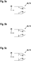
- the Figures 5a to 5c show a special variant in which the throttle 68 is an exchangeable fixed throttle 70.
- the fixed throttle 70 forms the end piece of the nozzle 54.
- the fixed throttle 70 is provided in three different designs, each with a different pressure drop.
- the fixed throttle 70 has a throttle plate 72.
- the throttle plate 72 is attached perpendicular to the flow direction of the fuel 28 in the fixed throttle. The fuel can only flow through a circular opening in the center of the throttle plate 72. In this way, the flow cross section of the fixed throttle 70 is reduced.
- the fixed throttle 70 has circular openings of different sizes in different designs.
- the illustrated embodiment of the fixed throttle 70 is provided for the use of L-gas as fuel 28.
- the embodiment of the fixed throttle 70 shown is intended for the use of H gas.
- the embodiment of the fixed throttle 70 shown is intended for the use of LPG.
- LPG or Liquefied Petroleum Gas is also called LPG.
- the Figures 6a to 6c show a further variant of an adjustable throttle 68.
- the nozzle 54 has a tapering tip which has a third outlet opening 74 at its end.
- the third outlet opening 74 is provided to guide the fuel 28 out of the nozzle 54.
- the throttle 68 is implemented by a needle 76 arranged axially in the nozzle 54.
- the needle 76 is within the nozzle 54 axially displaceable. In this way, the flow cross section of the nozzle 54 is reduced.
- the flow cross section and thus the pressure drop of the fuel 28 provided by the nozzle 54 can be adjusted by axially displacing the needle 76.
- the needle 76 advantageously has a cross-section or a cross-sectional area which largely corresponds to the cross-section or the cross-sectional area of the third outlet opening 74.
- the Figures 6a to 6c show different settings of the throttle 68 with the needle 76.
- the in Figure 6a The setting of the throttle 68 shown is intended for the use of L-gas.
- the setting of the throttle 68 shown is provided for the use of H gas.
- the setting of the throttle 68 shown is intended for the use of LPG.
- the needle 76 can be adjusted automatically, for example by an actuator.
- the needle 76 can advantageously be adjusted by the control device 22. In this way, the throttle 68 can be adjusted during operation. This is advantageous for quick consideration of fluctuations in the quality of the fuel 28.
Landscapes
- Engineering & Computer Science (AREA)
- Chemical & Material Sciences (AREA)
- Combustion & Propulsion (AREA)
- Mechanical Engineering (AREA)
- General Engineering & Computer Science (AREA)
- Gas Burners (AREA)
Description
- Die Erfindung betrifft eine Brennstoff-Luft-Mischeinrichtung, insbesondere für ein von einem Gebläse unterstütztes Heizgerät, umfassend einem Lufteinlass, ein äußeres Venturirohr mit einer ersten Engestelle, ein inneres Venturirohr mit einer zweiten Engstelle und einer Düse im Bereich der zweiten Engstelle zum Zuführen von Brennstoff. Die Erfindung betrifft auch ein Heizgerät mit einer Brennstoff-Luft-Mischeinrichtung gemäß der vorliegenden Erfindung.
- Die
DE102016201624A1 zeigt und beschreibt eine Brennstoff-Luft-Mischeinrichtung in der Form einer Venturi-Durchführung für einen von einem Gebläse unterstützten Brenner. Die Luftansaugung erfolgt durch das Gebläse, die Eindüsung des gasförmigen Brennstoffs in den Luftstrom ist vor dem Gebläse angeordnet. Aufgrund der Unterdruckverhältnisse im Bereich der Engstelle des Venturis wird der gasförmige Brennstoff dort automatisch eingesaugt. Heizgeräte mit einer solchen Anordnung haben den Vorteil, dass die Leistung über einen besonders großen Bereich (> 1:10) variiert werden kann. Um dabei den Leistungsverbrauch zu minimieren, sind bei heutigen Anforderungen an die Modulationsbreite der Leistung zunehmend größere Venturilängen notwendig Eine gattungsgemäße Brennstoff-Luft-Mischeinrichtung ist jeweils inFR1315223A DE10014347A1 undEP0149574A2 offenbart. - Gemäß der vorliegenden Erfindung wird eine Brennstoff-Luft-Mischeinrichtung gemäß Anspruch 1 offenbart.
- Das hat den Vorteil, dass der an der zweiten Engstelle des inneren Venturirohrs abgesenkte Druck auf einer kürzeren Strecke zurückgewonnen werden kann als beispielsweise in einem System mit nur einem Venturirohr. Das ermöglicht die Konstruktion einer kompakten Brennstoff-Luft-Mischeinrichtung.
- Unter einem "Venturirohr" ist ein Rohr zu verstehen, welches in einer Engstelle eine minimale Querschnittsfläche aufweist. Von der Engstelle ausgehend weitet sich das Venturirohr in Richtung einer Austrittsöffnung des Venturirohrs auf. Die Querschnittsfläche vergrößert sich von der Engstelle ausgehend in Richtung der Austrittsöffnung. Vorteilhaft weitet sich das Venturirohr von der Engstelle ausgehend in Richtung einer Eintrittsöffnung auf. Vorteilhaft vergrößert sich die Querschnittsfläche von der Engstelle ausgehend in Richtung der Austrittsöffnung. Bevorzugt ist die Querschnittsfläche des Venturirohrs kreisförmig oder weitgehend kreisförmig. Es sind auch andere Formen der Querschnittsfläche des Venturirohrs denkbar, insbesondere oval und/oder ellipsenförmig und/oder rechteckig und/oder polygonförmig. Unter der "Querschnittsfläche" soll die Querschnittsfläche des luftführenden bzw. gasführenden, insbesondere des Brennstoff-Luft-Gemisch führenden Teils des Venturirohrs verstanden werden.
- Das Venturirohr betreffende Merkmale mit dem vorgestellten Adjektiv "erste" betreffen in der vorliegenden Beschreibung das äußere Venturirohr. Das Venturirohr betreffende Merkmale mit dem vorgestellten Adjektiv "zweite" betreffen in der vorliegenden Beschreibung das innere Venturirohr. Eine "erste Engstelle" ist eine Engstelle des äußeren Venturirohrs. Eine "erste Austrittsöffnung" ist eine Austrittsöffnung des äußeren Venturirohrs. Eine "erste Eintrittsöffnung" ist eine Eintrittsöffnung des äußeren Venturirohrs. Eine "zweite Engstelle" ist eine Engstelle des inneren Venturirohrs. Eine "zweite Austrittsöffnung" ist eine Austrittsöffnung des inneren Venturirohrs. Eine "zweite Eintrittsöffnung" ist eine Eintrittsöffnung des inneren Venturirohrs.
- Unter einen "von einem Gebläse unterstützten Heizgerät" ist ein Heizgerät zu verstehen, bei dem ein Brenner hauptsächlich durch ein Gebläse mit Luft zur Verbrennung versorgt wird. Typischerweise wird in einem von Gebläse unterstützten Heizgerät bzw. Brenner ein bevorzugt gasförmiger Brennstoff in einen durch das Gebläse geförderten Luftstrom eingeführt bzw. durch eine Brennstoff-Luft-Mischeinrichtung eingemischt, so dass dem Brenner ein Brennstoff-Luft-Gemisch zugeführt wird. Die Luft wird durch das Gebläse angesaugt. Von einem durch das Gebläse unterstützten Brenner sind atmosphärische Brenner zu unterscheiden, bei denen am Brenner die freie, in der Umgebung vorhandene Luft zur Verbrennung genutzt wird. Beispiel für atmosphärische Brenner sind Bunsenbrenner oder Gas-Heizstrahler bzw. Gas-Infrarotstrahler.
- Durch die in den Unteransprüchen aufgeführten Merkmale sind vorteilhafte Weiterbildungen der Brennstoff-Luft-Mischeinrichtung möglich. Weist das äußere Venturirohr eine erste Austrittsöffnung auf, das innere Venturirohr eine zweite Austrittsöffnung auf und Ist die zweite Austrittsöffnung weitgehend an der ersten Engstelle des äußeren Venturirohrs angeordnet, hat das den Vorteil, dass das aus dem inneren Venturirohr ausströmende Brennstoff-Luft-Gemisch an einer Stelle minimalen Drucks im äußeren Venturirohr einströmt. Auf diese Weise wird die Druckdifferenz zwischen der zweiten Engstelle des inneren Venturis und der ersten Austrittsöffnung des äußeren Venturis besonders groß. Das ermöglicht die Konstruktion einer besonders kompakten Brennstoff-Luft-Mischeinrichtung. Unter "die zweite Austrittsöffnung ist weitgehend an der ersten Engstelle angeordnet" soll verstanden werden, dass ein Abstand der zweiten Austrittsöffnung bezüglich einer Längsrichtung der Brennstoff-Luft-Mischeinrichtung zu der ersten Engstelle kleiner ist als 10 % einer Venturilänge des äußeren Venturirohrs, bevorzugt kleiner als 4 %, besonders bevorzugt kleiner als 1 %. Die Längsrichtung der Brennstoff-Luft-Mischeinrichtung ist parallel zu einer Längsachse bzw. Symmetrieachse der Brennstoff-Luft-Mischeinrichtung angeordnet und zeigt von der ersten Eintrittsöffnung bzw. vom Lufteinlass zur ersten Austrittsöffnung. Die Längsrichtung zeigt weitgehend in die Richtung des in die Brennstoff-Luft-Mischeinrichtung einströmenden Luftstroms bzw. des ausströmenden Brennstoff-Luft-Gemischs. Der Abstand der zweiten Austrittsöffnung zur ersten Engstelle bezüglich der Längsrichtung wird zwischen einer ersten Ebene, die in der zweiten Austrittsöffnung liegt, und einer zweiten Ebene, die in der ersten Engstelle liegt, entlang der Längsrichtung gemessen. Bevorzugt liegt die erste Ebene auf einem äußersten Rand des inneren Venturirohrs, welcher sich an der Seite der zweiten Austrittsöffnung befindet. Bevorzugt bildet der äußere Rand die zweite Austrittsöffnung. Bevorzugt schneidet die zweite Ebene das äußere Venturi so, dass eine entsprechende Querschnittsfläche minimal ist. Die "Venturilänge" ist der Abstand der ersten Engstelle zur ersten Austrittsöffnung entlang der Längsrichtung.
- Dadurch, dass die Düse weitgehend konzentrisch innerhalb des inneren Venturirohrs angeordnet ist, strömt die resultierende Brennstoff-Luft-Mischung weitgehend laminar. Auf diese Weise wird eine besonders hohe Druckrückgewinnung durch die Brennstoff-Luft-Mischeinrichtung ermöglicht. Eine weniger symmetrische Anordnung der Düse kann zu Turbulenzen bzw. Verwirbelungen führen, welche einen Druckabfall bewirken. Unter "weitgehend konzentrisch" soll verstanden werden, dass einer Symmetrieachse der Düse zu einer Symmetrieachse des inneren Venturirohrs weitgehend parallel angeordnet ist und der Abstand der Symmetrieachse der Düse zur Symmetrieachse des inneren Venturirohrs weniger als 10 % eines Venturidurchmessers des inneren Venturirohrs beträgt, bevorzugt weniger als 4 %, besonders bevorzugt weniger als 1 %.
- Ist das innere Venturirohr weitgehend konzentrisch innerhalb des äußeren Venturirohrs angeordnet, wird eine laminar strömende Brennstoff-Luft-Mischung noch besser ermöglicht. Unter "weitgehend konzentrisch" soll verstanden werden, dass die Symmetrieachse des inneren Venturirohrs zu einer Symmetrieachse des äußeren Venturirohrs bzw. zur Symmetrieachse der Brennstoff-Luft-Mischeinrichtung weitgehend parallel angeordnet ist und der Abstand der Symmetrieachse des inneren Venturirohrs zur Symmetrieachse des äußeren Venturirohrs weniger als 10 % eines Venturidurchmessers des äußeren Venturirohrs beträgt, bevorzugt weniger als 4 %, besonders bevorzugt weniger als 1 %.
- Eine möglichst laminar strömende Brennstoff-Luft-Mischung kann sichergestellt werden, wenn das innere Venturirohr und/oder das äußere Venturirohr einen jeweils weitgehend kreisförmigen Querschnitt aufweisen. Auf diese Weise wird die Symmetrie der Brennstoff-Luft-Mischeinrichtung weiter erhöht. Unter "Querschnitt" soll die Form der Querschnittsfläche des luftführenden bzw. gasführenden, insbesondere des Brennstoff-Luft-Gemisch führenden Teils des Venturirohrs verstanden werden
- Erfindungsgemäß ist die erste Eintrittsöffnung des äußeren Venturirohrs bezüglich der Längsrichtung der Brennstoff-Luft-Mischeinrichtung weitgehend an der zweiten Eintrittsöffnung des inneren Venturirohrs angeordnet. Dadurch kann die Laminarität der einströmenden Luft verbessert werden. Unter "die erste Eintrittsöffnung ist weitgehend an der zweiten Eintrittsöffnung angeordnet" soll verstanden werden, dass ein Abstand der ersten Eintrittsöffnung bezüglich der Längsrichtung der Brennstoff-Luft-Mischeinrichtung zu der zweiten Eintrittsöffnung kleiner ist als 10 % der Venturilänge des äußeren Venturirohrs, bevorzugt kleiner als 4 %, besonders bevorzugt kleiner als 1 %. Der Abstand der ersten Eintrittsöffnung zur zweiten Eintrittsöffnung bezüglich der Längsrichtung wird zwischen einer dritten Ebene, die in der ersten Eintrittsöffnung liegt, und einer vierten Ebene, die in der zweiten Eintrittsöffnung liegt, entlang der Längsrichtung gemessen. Bevorzugt liegt die dritte Ebene auf einem äußersten Rand des äußeren Venturirohrs, welcher sich an der Seite der ersten Eintrittsöffnung befindet. Bevorzugt liegt die vierte Ebene auf einem äußersten Rand des inneren Venturirohrs, welcher sich an der Seite der zweiten Eintrittsöffnung befindet.
- Weist die Düse eine einstellbare Drossel zur Verminderung des durch die Düse strömenden Brennstoffs auf, insbesondere eine auswechselbare Festdrossel, hat das den Vorteil, dass die Brennstoff-Luft-Mischeinrichtung an unterschiedliche Brennstoffarten angepasst werden kann.
- Unter einer "Drossel" ist ein Bauelement zu verstehen, welches einen Druckabfall in einem durchströmenden und/oder vorbeiströmenden Gas bzw. Fluid bewirkt. Beispielsweise kann eine Drossel eine senkrecht zur Strömungsrichtung des Brennstoffs eingebrachten Platte sein. Eine Drossel verringert einen Strömungsquerschnitt des Gases bzw. Fluids. Unter "einstellbarer Drossel" soll eine Drossel verstanden werden, bei der der Druckabfall einstellbar ist. Eine "auswechselbare Festdrossel" ist ein auswechselbares, an der Düse anbringbares Bauelement, welches einen vorgegebenen Druckabfall des Brennstoffs bewirkt. Es ist vorgesehen, dass unterschiedliche auswechselbare Festdrosseln mit jeweils unterschiedlichen vorgegebenen Druckabfällen an der Düse anbringbar sind, insbesondere zur Anpassung der Düse bzw. der Brennstoff-Luft-Mischeinrichtung an unterschiedliche Brennstoffsorten.
- Für ein Heizgerät mit einem von einem Gebläse unterstützten Brenner und einer Brennstoff-Luft-Mischeinrichtung gemäß der vorliegenden Erfindung, die einem durch das Gebläse angesaugtem Luftstrom über eine Brennstoffleitung insbesondere gasförmigen Brennstoff zuführt, ergeben sich darüber hinaus weitere Vorteile. So kann ein solches Heizgerät besonders kompakt konstruiert werden. Zusätzlich bietet eine kompakte Brennstoff-Luft-Mischeinrichtung mehr Möglichkeiten, wo und mit welcher Ausrichtung die Brennstoff-Luft-Mischeinrichtung im Heizgerät verbaubar ist. Das ermöglicht eine besonders sichere und/oder zuverlässige Konstruktion des Heizgeräts. Weiterhin kann auf diese Weise der Zugang zu Komponenten des Heizsystems bei einer Wartung und/oder Inspektion verbessert werden.
- Stellt das Gebläse der Brennstoff-Luft-Mischeinrichtung Luft mit einem einstellbaren Luftstrom bereit, ist auf diese Weise die Brennerleistung besonders zuverlässig einstellbar. Unter "einstellbaren Luftstrom" soll ein einstellbarer Volumenluftstrom verstanden werden. Beispielsweise kann der Luftstrom über ein Gebläse mit einer variablen Gebläsedrehzahl und/oder variablen Gebläseleistung eingestellt werden.
- Stellt ein Brennstoffregelventil den Brennstoff mit einem vorbestimmbaren, insbesondere konstanten Druck bereit, hat das den Vorteil, dass auf diese Weise das Brennstoff-Luft-Verhältnis besonders zuverlässig eingestellt werden kann. Insbesondere ist es möglich, das Brennstoff-Luft-Verhältnis konstant auf einen vorgegebenen Wert einzustellen. Auf diese Weise ist ein sauberer und umweltfreundlicher Betrieb des Heizgeräts möglich. Insbesondere kann der Druck des Brennstoffs auf den Umgebungsdruck bzw. auf einen Umgebungsdruck mit einem Offset geregelt werden. Beispielsweise kann das Brennstoffregelventil ein pneumatisches Regelventil sein, insbesondere ein Nulldruckregler. Auf diese Weise kann das Brennstoffregelventil sehr schnell auf Änderungen des Umgebungsdrucks reagieren und ein weitgehend konstantes Brennstoff-Luft-Verhältnis ermöglichen.
- In den Zeichnungen sind Ausführungsbeispiele der Brennstoff-Luft-Mischeinrichtung gemäß der vorliegenden Erfindung sowie des Heizgeräts gemäß der vorliegenden Erfindung dargestellt und in der nachfolgenden Beschreibung näher erläutert. Es zeigen
-
Figur 1 ein schematische Darstellung eines Heizgeräts mit einer Brennstoff-Luft-Mischeinrichtung gemäß der vorliegenden Erfindung, -
Figur 2 eine schematische Darstellung der Brennstoff-Luft-Mischeinrichtung, -
Figuren 3a bis 4b einen Vergleich einer Brennstoff-Luft-Mischeinrichtung gemäß der vorliegenden Erfindung mit dem Stand der Technik sowie einen Vergleich des Druckverlaufs in den jeweiligen Brennstoff-Luft-Mischeinrichtungen und -
Figuren 5a bis 6c schematische Darstellungen von verschiedenen Darstellungen von Drosseln für die Brennstoff-Luft-Mischeinrichtung. - In den verschiedenen Ausführungsvarianten erhalten gleiche Teile die gleichen Bezugszahlen.
-
Figur 1 sind schematisch Komponenten eines Heizgeräts 10 abgebildet. Das Heizgerät 10 umfasst weitere, nicht abgebildete Komponenten wie beispielsweise einen Wärmetauscher, Pumpen oder ein Abgassystem. Die Art und Anzahl der Komponenten hängt von Ausstattungsgrad des Heizgeräts ab. -
Figur 1 zeigt eine Brennstoff-Luft-Mischeinrichtung 12, ein Gebläse 14, einen Brenner 16, ein Brennstoffventil 18, eine lonisationssonde 20 und eine Steuereinheit 22 auf. Ist das Heizgerät 10 in Betrieb, weist der Brenner 16 eine Flamme 24 auf. Die Ionisationssonde 20 ragt in die Flamme 24. Das Gebläse 14 ist dazu vorgesehen, Luft 26 anzusaugen. Eine Gebläsedrehzahl des Gebläses 14 ist variabel einstellbar. Die Brennstoff-Luft-Mischeinrichtung 12 ist dazu vorgesehen, die angesaugte Luft 26 mit einem Brennstoff 28 zu einem Brennstoff-Luft-Gemisch 30 zu vermischen. Der Brennstoff 28 wird über eine Brennstoffleitung 32 durch das Brennstoffventil 16 und anschließend in die Brennstoff-Luft-Mischeinrichtung 12 geleitet. Das Brennstoffventil 16 ist dazu vorgesehen, den Brennstoff 28 auf einem vorbestimmbaren Druck bereitzustellen. - Das Brennstoffventil 16 ist im Ausführungsbeispiel als pneumatischer Nulldruckregler ausgeführt. Der Brennstoff 28 wird der Brennstoff-Luft-Mischeinrichtung 12 auf einem Druck, der weitgehend dem Umgebungsdruck entspricht, bereitgestellt. In alternativen Ausführungen wird der Brennstoff 28 auf einem Druck bereitgestellt, der weitgehend dem Umgebungsdruck abzüglich oder zuzüglich eines Offsets entspricht. In weiteren Ausführungsformen wird der Brennstoff 28 mit dem Brennstoffventil 18 auf einen fest vorgegebenen Druck eingestellt. Es ist auch denkbar, dass der Druck des Brennstoffs 28 je nach Bedarf veränderbar ist, beispielsweise in Abhängigkeit von Betriebsbedingungen und/oder äußeren Bedingungen. Beispielsweise kann das Brennstoffventil 16 ein elektrisch einstellbares Ventil sein, welches durch die Steuereinheit 22 einstellbar ist. Der Druck des Brennstoffs 28 kann etwa in Abhängigkeit von einem Betriebsmodus des Heizgeräts 10, von einer durch die Steuereinheit 22 ermittelten Brennstoffart und/oder von einer gewünschten Heizleistung einstellbar sein.
- Das Gebläse 14 ist dazu vorgesehen, das Brennstoff-Luft-Gemisch 30 bzw. einen Brennstoff-Luft-Gemischstrom 30 in den Brenner 16 zu leiten.
- Die Steuereinheit 22 ist über Busleitungen 34 mit den Komponenten des Heizgeräts 10 verbunden, insbesondere mit dem Gebläse 14 und der Ionisationssonde 20. Die Steuereinheit 22 ist dazu vorgesehen, einen Luftstrom 26 der angesaugten Luft 26 zu regeln, insbesondere ist die Steuereinheit 22 dazu vorgesehen, die Gebläsedrehzahl des Gebläses 14 einzustellen. Die eingestellte Gebläsedrehzahl des Gebläses 14 bzw. der eingestellte Luftstrom 26, der durch das Gebläse gefördert wird, richtet sich insbesondere nach einer angeforderten Heizleistung des Heizsystems 10.
- Die Steuereinheit 22 ist im Ausführungsbeispiel dazu vorgesehen, Messwerte von der Ionisationssonde 20 zu empfangen. Die Ionisationssonde 20 misst einen lonisationsstrom der Flammen 24. Der lonisationsstrom ermöglicht Rückschlüsse auf die am Brenner 16 stattfindende Verbrennung. Beispielsweise sind aus dem lonisationsstrom Rückschlüsse auf eine Qualität der Verbrennung möglich, insbesondere auf ein Brennstoff-Luft-Verhältnis des Brennstoff-Luft-Gemischs 30, oder auf eine Qualität und/oder Art bzw. Sorte des Brennstoffs 28. Insbesondere ist mit Hilfe der lonisationssonde 20 feststellbar, ob eine Flamme 24 vorhanden ist.
- Die Steuereinheit 22 kann in einer bevorzugten Ausführungsformen dazu vorgesehen sein, das Heizsystem in Abhängigkeit vom lonisationsstrom zu steuern bzw. zu regeln. Beispielsweise kann die Steuereinheit 22 ein elektronisches Brennstoffventil 18 ansteuern um das Brennstoff-Luft-Verhältnis in Abhängigkeit vom lonisationsstrom anzupassen. Das kann etwa bei einer Änderung der Brennstoffart und/oder einer Brennstoffqualität notwendig sein.
-
Figur 2 zeigt eine Detailansicht der Brennstoff-Luft-Mischeinrichtung 12 des Ausführungsbeispiels. Die Brennstoff-Luft-Mischeinrichtung 12 umfasst ein äußeres Venturirohr 36 und ein inneres Venturirohr 38. Das innere Venturirohr 38 ist innerhalb des äußeren Venturirohrs 36 angeordnet. Das äußere Venturirohr 36 weist eine erste Engstelle 40 auf. Das innere Venturirohr 38 weist eine zweite Engstelle 42 auf. Das äußere Venturirohr 36 weist eine erste Austrittsöffnung 44 auf. Das innere Venturirohr 38 weist eine zweite Austrittsöffnung 46 auf. Die erste Austrittsöffnung 44 ist dazu vorgesehen, ein Brennstoff-Luft-Gemisch 30 aus dem äußeren Venturirohr 36 herauszuleiten. Die zweite Austrittsöffnung 46 ist dazu vorgesehen, ein Brennstoff-Luft-Gemisch 30 aus dem inneren Venturirohr 38 herauszuleiten. - Das äußere Venturirohr 36 weist eine erste Eintrittsöffnung 48 auf. Das innere Venturirohr 38 weist eine zweite Eintrittsöffnung 50 auf. Die erste Eintrittsöffnung 48 ist dazu vorgesehen, Luft 26 in das äußere Venturirohr 36 einzuleiten. Die zweite Eintrittsöffnung 50 ist dazu vorgesehen, Luft 26 in das innere Venturirohr 38 einzuleiten. Die erste Eintrittsöffnung 48 und die zweite Eintrittsöffnung 50 bilden einen Lufteinlass 52 der Brennstoff-Luft-Mischeinrichtung 12.
- Die Brennstoff-Luft-Mischeinrichtung 12 weist eine Düse 54 auf. Die Düse 12 ist mit der Brennstoffleitung 32 verbunden. Die Düse 54 ist dazu vorgesehen, Brennstoff 28 in die Brennstoff-Luft-Mischeinrichtung 12 einzuleiten. Die Düse 54 ist im Bereich der zweiten Engstelle 42 angeordnet. Im Ausführungsbeispiel ist die zweite Austrittöffnung 46 im Bereich der ersten Engstelle 40 angeordnet.
- Die Brennstoff-Luft-Mischeinrichtung 12 ist im Ausführungsbeispiel zylindersymmetrisch bzw. rotationssymmetrisch aufgebaut. Die wesentlichen, in
Figur 2 abgebildeten Komponenten der Brennstoff-Luft-Mischeinrichtung 12 sind rotationssymmetrisch bezüglich einer Längsachse 55. Insbesondere das äußere Venturirohr 36 und das innere Venturirohr 38 sind weitgehend rotationssymmetrisch bezüglich der Längsachse 55. Eine Längsrichtung 57 ist parallel zur Längsachse 55 angeordnet und zeigt in die Richtung des in die Brennstoff-Luft-Mischeinrichtung 12 eingesaugten Luftstroms 26 bzw. in die Richtung des aus der Brennstoff-Luft-Mischeinrichtung 12 ausströmenden Brenstoff-Luft-Gemischstroms 30. - Die
Figuren 3a und 3b in Verbindung mit denFiguren 4a und 4b veranschaulichen das Funktionsprinzip der Brennstoff-Luft-Mischeinrichtung 12 gemäß des Ausführungsbeispiels.Figur 3a zeigt ein einteiliges Venturisystem gemäß des Standes der Technik. Durch das hinter der Brennstoff-Luft-Mischeinrichtung 12 angeordnete Gebläse 14 (sieheFigur 1 ) wird durch den Lufteinlass 52 Luft 26 angesaugt. - Die Abszissenachse 56 in den
Figuren 4a und 4b bildet den Ort entlang der Längsachse 55 bzw. Symmetrieachse der Brennstoff-Luft-Mischeinrichtung 12 ab. Die Ordinatenachse 58 zeigt einen Druck 60 der Luft 26 und/oder einen Druck 60 des Brennstoff-Luft-Gemischs 30. Durch den enger werdenden Querschnitt bzw. die kleiner werdende Querschnittsfläche des äußeren Venturirohrs 36 erhöht sich zunächst die Geschwindigkeit des Luftstroms, der Druck 60 der Luft 26 sinkt. An der ersten Engstelle 40 erreicht der Druck 60 der Luft 26 sein Minimum. Die Düse 54 ist an der ersten Engstelle 40 angeordnet, so dass der Brennstoff 28 durch den Luftstrom angesaugt wird. Der Druck an der ersten Engstelle 40 heißt Steuerdruck 62. - Nach der ersten Engstelle 40 weitet sich die Querschnittsfläche des äußeren Venturirohrs 36 in Strömungsrichtung bzw. in Richtung der ersten Austrittsöffnung 44. Auf diese Weise wird der Druck 60 des Brennstoff-Luft-Gemischs 30 erhöht. Der ursprünglich an der Einlassöffnung 52 vorhandene Druck 60 wird zurückgewonnen. An der ersten Austrittsöffnung 44 unterscheidet sich Druck 60 vom an der Einlassöffnung 52 vorhandenen Druck um einen Druckverlust 64. Je niedriger der Druckverlust 64, umso geringer ist der Leistungsverbrauch des Gebläses 14. Auf diese Weise sind hohe Modulationsbreiten des Heizgeräts 10 möglich, das heißt, das Verhältnis von maximal möglicher Heizleistung des Heizgeräts 10 zu minimal möglicher Heizleistung des Heizgeräts 10 ist hoch. Mit Hilfe einer Brennstoff-Luft-Mischeinrichtung 12 mit einem Venturi als Drossel sind Modulationsbreiten von über 1:10 realisierbar.
- Die Druckrückgewinnung zwischen der ersten Engstelle 40 und der ersten Austrittsöffnung 44 ist umso größer, je stärker sich die Querschnittsfläche des äußeren Venturirohrs 36 von der ersten Engstelle 40 bis zur ersten Austrittsöffnung 44 vergrößert. Die Drückrückgewinnung zwischen der ersten Engstelle 40 und der ersten Austrittsöffnung 44 ist umso größer, je größer die Querschnittsfläche des äußeren Venturirohrs 36 an der ersten Austrittsöffnung 44 im Vergleich zur Querschnittsfläche des äußeren Venturirohrs 36 an der ersten Engstelle 40 ist. Je größer die Druckrückgewinnung zwischen der ersten Engstelle 40 und der ersten Austrittsöffnung 44, umso geringer ist der Druckverlust 64.
- Sind die Querschnittsfläche des äußeren Venturirohrs 36 an der ersten Austrittsöffnung 44 und die Querschnittsfläche des äußeren Venturirohrs 36 an der ersten Engstelle 40 vorgegeben, so ist dafür eine bestimmte Venturilänge 66 notwendig. Die Venturilänge 66 ist der Abstand zwischen der ersten Engstelle 40 und der ersten Austrittsöffnung 44. Die Venturilänge 66 darf einen minimalen Wert nicht unterschreiten, ansonsten reißt die Strömung ab und ist nicht mehr laminar. Der minimale Wert der Venturilänge 66 hängt von der Querschnittsfläche des äußeren Venturirohrs 36 an der ersten Austrittsöffnung 44 und von der Querschnittsfläche des äußeren Venturirohrs 36 ab.
- Im in
Figur 3a gezeigten Beispiel beträgt die Querschnittsfläche des äußeren Venturirohrs 36 an der ersten Engstelle 1 cm^2, die Querschnittsfläche des äußeren Venturirohrs 36 an der ersten Austrittsöffnung 44 beträgt 7 cm^2. Die Venturilänge 66 beträgt 15 cm. - Je größer das Verhältnis von der Querschnittsfläche des äußeren Venturirohrs 36 an der ersten Austrittsöffnung 44 zur Querschnittsfläche des äußeren Venturirohrs 36 an der ersten Engstelle 40, umso größer ist der minimale Wert der Venturilänge 66. Je stärker der Druckverlust minimiert werden soll bzw. je größer die Druckrückgewinnung sein soll, umso größer ist die Venturilänge 66. Ein besonders effizientes Heizgerät 10 benötigt daher nach dem Stand der Technik eine längere Brennstoff-Luft-Mischeinrichtung 12.
- In
Figur 3b ist die Brennstoff-Luft-Mischeinrichtung 12 des Ausführungsbeispiels sowie der Verlauf des Drucks 60 entlang der Längsachse 55 bzw. Symmetrieachse der Brennstoff-Luft-Mischeinrichtung 12 abgebildet. Im Ausführungsbeispiel wird bei gleichem Steuerdruck 62 und bei gleichem Druckverlust 64 gegenüber dem inFigur 3a abgebildeten Stand der Technik eine kleinere Venturilänge 66 benötigt. Das ermöglicht die Konstruktion einer kompakteren Brennstoff-Luft-Mischeinrichtung 12. - Im Ausführungsbeispiel nimmt das äußere Venturirohr 36 einen Großteil des Luft 26a bzw. des Luftstroms auf (siehe
Figur 3b ). Das innere Venturirohr 38 nimmt einen kleineren Teil der Luft 26b bzw. des Luftstroms auf. Der Brennstoff 28 wird in der zweiten Engstelle 42 des inneren Venturirohrs 38 eingedüst. Die zweite Austrittsöffnung 46 des inneren Venturirohrs 38 ist an der ersten Engstelle 40 des äußeren Venturirohrs 36 angeordnet. An der ersten Engstelle 40 hat der durch das äußere Venturirohr abgesenkte Druck 60a des Luftstroms bzw. des Brennstoff-Luft-Stroms sein Minimum. Gegenüber dem Druck 60a an der ersten Engstelle 40 wird der Druck 60b in der zweiten Engstelle 42 weiter abgesenkt (sieheFigur 3b ). An der zweiten Engstelle 42 wird ein Steuerdruck 62 erreicht, der weitgehend dem Steuerdruck 62 im inFigur 3a gezeigten System entspricht. - Der Steuerdruck 62 wird an der zweiten Engstelle 42 erzeugt, wobei nur ein Teil der insgesamt der Brennstoff-Luft-Mischeinrichtung 12 zugeführten Luft 26 auf eine maximale Geschwindigkeit in der zweiten Engstelle 42 beschleunigt werden muss. Gegenüber dem in
Figur 3a abgebildeten einteiligen Venturisystem strömt die äußere Luft 26a durch eine größere Querschnittsfläche bei niedrigerer Geschwindigkeit. Der Druck 60 kann auf einer kürzeren Venturilänge 66 zurückgewonnen werden. - Im Ausführungsbeispiel (
Figur 3b ) beträgt beträgt die Querschnittsfläche des äußeren Venturirohrs 36 an der ersten Austrittsöffnung 44 7 cm^2. Die Querschnittsfläche des äußeren Venturirohrs 36 an der ersten Engstelle 40 2.7 cm^2. Die Querschnittsfläche des des inneren Venturirohrs 38 an der zweiten Austrittsöffnung 46 beträgt 0.5 cm^2. Die Querschnittsfläche des inneren Venturirohrs 38 an der zweiten Engstelle 42 beträgt 0.3 cm^2. Die Venturilänge 66 beträgt 10 cm. - In alternativen Ausführungsformen sind andere Maße der Querschnittsflächen der Venturirohre 36 und/oder 38 denkbar. In bevorzugten Ausführungsformen beträgt die Querschnittsfläche des äußeren Venturirohrs 36 an der ersten Engstelle 40 zwischen 30 % und 60 %, besonders bevorzugt zwischen 40 % und 50 % des Querschnitts des äußeren Venturirohrs 36 an der ersten Austrittsöffnung 44. In bevorzugten Ausführungsformen beträgt die Querschnittsfläche des inneren Venturirohrs 38 an der zweiten Austrittsöffnung 46 zwischen 5 % und 30 %, besonders bevorzugt zwischen 10 % und 20 % des Querschnitts des äußeren Venturirohrs 36 an der ersten Austrittsöffnung 44. In bevorzugten Ausführungsformen beträgt die Querschnittsfläche des inneren Venturirohrs 38 an der zweiten Engstelle 42 zwischen 40 % und 70 %, besonders bevorzugt zwischen 50 % und 60 % des Querschnitts des inneren Venturirohrs 38 an der zweiten Austrittsöffnung 46.
- Im Ausführungsbeispiel ist die zweite Austrittsöffnung 46 im axialen Bereich an der ersten Engstelle 40 angeordnet. Die zweite Austrittsöffnung 46 ist an der Längsachse 55 bzw. an einer Symmetrieachse des äußeren Venturirohrs 36 angeordnet. Auf diese Weise wird der Steuerdruck 62 minimal. Die Druckrückgewinnung wird so maximal. In alternativen Ausführungsformen ist es denkbar, dass die zweite Austrittsöffnung 46 gegenüber der Engstelle 40 einen Abstand bezüglich der Längsrichtung 57 hat. Auf diese Weise kann über diesen Abstand der Steuerdruck 62 vergrößert bzw. eingestellt werden. Das kann beispielsweise zur Anpassung der Brennstoff-Luft-Mischeinrichtung 12 an unterschiedliche Brennstoffarten vorteilhaft sein.
- In besonders vorteilhaften Ausführungsformen ist das innere Venturirohr 38 gegenüber dem äußeren Venturirohr 36 axial verschiebbar. Abhängig von der Position des inneren Venturirohrs 38 ändert sich der Abstand der zweiten Austrittsöffnung 46 von der ersten Engstelle 40. Auf diese Weise lässt sich der Steuerdruck 62 auf einen gewünschten Wert einstellen, falls notwendig auch im Betrieb des Heizsystems 10. Es ist denkbar, dass die Position des inneren Venturirohrs 38 durch einen elektronischen Stellantrieb verstellbar ist, insbesondere durch das Steuergerät 22.
- Weiterhin ist es denkbar, dass die Position der Düse 54 gegenüber dem inneren Venturirohr 38 axial verstellbar ist. Auf diese Weise kann ein Abstand der Düse 54 von der zweiten Engstelle 42 bezüglich der Längsrichtung 57 eingestellt werden. Auf diese Weise lässt sich der Steuerdruck 62 auf einen gewünschten Wert einstellen, falls notwendig auch im Betrieb des Heizsystems 10. Es ist denkbar, dass die Position der Düse 54 durch einen elektronischen Stellantrieb verstellbar ist, insbesondere durch das Steuergerät 22.
- In besonders vorteilhaften Ausführungsformen sind die Düse 54 und das innere Venturirohr 38 axial verstellbar. Auf diese Weise lässt sich der Steuerdruck 62 besonders präzise und zuverlässig einstellen.
- Im Ausführungsbeispiel ist die Düse 54 konzentrisch innerhalb des inneren Venturirohrs 38 angeordnet. Auf diese Weise strömt der Brennstoff 28 weitgehend zentral in die durch das innere Venturirohr 38 geführte Luft 26b (siehe
Figur 3b ). In alternativen Ausführungen ist die Düse 54 nicht konzentrisch im äußeren Venturirohr 36 angeordnet. Durch den asymmetrisch in die Luft 26b einströmenden Brennstoff 28 werden Turbulenzen bzw. Verwirbelungen im Brennstoff-Luft-Gemisch 30 begünstigt. Das kann für eine besonders gute Durchmischung des Brennstoff-Luft-Gemischs 30 vorteilhaft sein. - In besonderen Ausführungsformen hat eine Symmetrieachse der Düse 54 einen Abstand zwischen 10 % und 50 %, bevorzugt zwischen 20 % und 40 %, besonders bevorzugt weitgehend 30 % eines Venturidurchmessers des inneren Venturirohrs 38 zur Längsachse 55 und/oder zu einer Symmetrieachse des inneren Venturirohrs 38. Es ist denkbar, dass zwischen der Symmetrieachse der Düse 54 und der Symmetrieachse des inneren Venturirohrs 38 ein Winkel zwischen 5 ° und 20 °, bevorzugt zwischen 10 ° und 15 ° vorliegt, insbesondere ein einstellbarer Winkel. Auf diese Weise sind Turbulenzen bzw. Verwirbelungen im Brennstoff-Luft-Gemisch 30 begünstigbar.
- Im Ausführungsbeispiel ist das innere Venturirohr 38 konzentrisch innerhalb des äußeren Venturirohrs 36 angeordnet. Auf diese Weise strömt die aus dem inneren Venturirohr 38 austretende Brennstoff-Luft-Mischung 30 weitgehend zentral in die durch das äußere Venturirohr 36 geführte Luft 26a (siehe
Figur 3b ). In alternativen Ausführungsformen ist das innere Venturirohr 38 nicht konzentrisch im äußeren Venturirohr 36 angeordnet. Durch die asymmetrisch in die durch das äußere Venturirohr 36 geführte Luft 26a einströmende Brennstoff-Luft-Mischung 30 werden Turbulenzen bzw. Verwirbelungen im aus der ersten Austrittsöffnung 44 ausströmenden Brennstoff-Luft-Gemisch 30 begünstigt. Das kann für eine besonders gute Durchmischung des Brennstoff-Luft-Gemischs 30 vorteilhaft sein. - In besonderen Ausführungsformen hat eine Symmetrieachse des inneren Venturirohrs einen Abstand zwischen 10 % und 50 %, bevorzugt zwischen 20 % und 40 %, besonders bevorzugt weitgehend 30 % eines Venturidurchmessers des äußeren Venturirohrs 36 zur Längsachse 55 und/oder zu der Symmetrieachse des äußeren Venturirohrs 36. Es ist denkbar, dass zwischen der Symmetrieachse des inneren Venturirohrs 38 und der Symmetrieachse des äußeren Venturirohrs 36 ein Winkel zwischen 5 ° und 20 °, bevorzugt zwischen 10 ° und 15 ° vorliegt, insbesondere ein einstellbarer Winkel. Auf diese Weise sind Turbulenzen bzw. Verwirbelungen im Brennstoff-Luft-Gemisch 30 begünstigbar.
- In besonderen Ausführungen ist es denkbar, dass die Düse 54 und/oder das innere Venturirohr 38 radial bzw. senkrecht zur Längsachse 55 bzw. Symmetrieachse der Brennstoff-Luft-Mischeinrichtung 12 verstellbar ist bzw. sind, insbesondere durch einen Stellantrieb. Auf diese Weise ist die Stärke der Turbulenz bzw. Verwirbelung des Brennstoff-Luft-Gemischs 30 einstellbar.
- Im Ausführungsbeispiel hat das äußere Venturirohr 36 einen kreisförmigen Querschnitt. Das innere Venturirohr 38 hat einen kreisförmigen Querschnitt. Die Düse 54 hat einen kreisförmigen Querschnitt. Dadurch wird ein Brennstoffstrom mit weitgehend kreisförmigen Querschnitt zentral in einen Luftstrom mit weitgehend kreisförmigen Querschnitt eingedüst. Das ermöglicht eine besonders laminare Strömung. In weiteren Varianten sind Brennstoff-Luft-Mischeinrichtung 12 mit alternativen Geometrien der Querschnitte des äußeren Venturirohrs 36 und/oder des inneren Venturirohrs 38 und/oder der Düse 54 denkbar. Beispielsweise ist es möglich, dass das äußere Venturirohr 36, das innere Venturirohr 38 und die Düse 54 einen weitgehend rechteckigen und/oder ovalen Querschnitt haben. Auf diese Weise hat der in die Luft 26 eingeströmte Brennstoff 28 im Querschnitt eine unterschiedliche Länge und Breite, was die Entstehung von Strömungsinstabilitäten und somit Turbulenzen bzw. Verwirbelungen begünstigt.
- Es ist denkbar, dass sich der Querschnitt des äußeren Venturirohrs 36 und/oder des inneren Venturirohrs 38 entlang der Länge der Brennstoff-Luft-Mischeinrichtung 12 verändert. Beispielsweise kann das äußere Venturirohr 36 einen weitgehend kreisförmigen Querschnitt haben, welcher sich erst in der Nähe der ersten Austrittsöffnung 44 stetig in einen ovalen Querschnitt ändert. Auf diese Weise werden Turbulenzen bzw. Verwirbelungen erst dann begünstigt, sobald ein großer Teil des Drucks 60 zurückgewonnen wurde.
- Im Ausführungsbeispiel ist die zweite Eintrittsöffnung 50 an der ersten Eintrittsöffnung 48 angeordnet (siehe
Figur 2 ). Auf diese Weise können Turbulenzen bzw. Verwirbelungen verhindert werden, da so die unmittelbar am inneren Venturirohr 38 vorbeiströmende Luft 26a (sieheFigur 3b ) eine geringe Geschwindigkeit hat. Es sind alternative Ausführungsformen denkbar, in denen das innere Venturirohr 38 tiefer im äußeren Venturirohr 36 angeordnet ist, so dass die zweite Eintrittsöffnung 50 einen größeren Abstand bezüglich der Längsrichtung 57 zur ersten Eintrittsöffnung 48 hat. In solchen Ausführungsformen sind Turbulenzen bzw. Verwirbelungen durch eine aerodynamisch günstige Form des inneren Venturirohrs 38 verhinderbar. - Im Ausführungsbeispiel hat die Düse 54 eine feste Form, insbesondere einen konstanten Öffnungsquerschnitt. In Varianten des Ausführungsbeispiels hat die Düse 54 eine einstellbare Drossel 68. Die Drossel 68 ist zur Verminderung bzw. Einstellung des Ducks des durch die Düse 54 bereitgestellten Brennstoffs 28 vorgesehen.
- Die
Figuren 5a bis 5c zeigen eine besondere Variante, in der die Drossel 68 eine auswechselbare Festdrossel 70 ist. Die Festdrossel 70 bildet das Endstück der Düse 54. Die Festdrossel 70 ist in drei unterschiedlichen Ausführungen mit einem jeweils unterschiedlichen Druckabfall vorgesehen. Die Festdrossel 70 weist eine Drosselplatte 72 auf. Die Drosselpatte 72 ist senkrecht zur Strömungsrichtung des Brennstoffs 28 in der Festdrossel angebracht. Der Brennstoff kann nur durch eine kreisförmige Öffnung in der Mitte der Drosselplatte 72 strömen. Auf diese Weise wird der Strömungsquerschnitt der Festdrossel 70 verkleinert. Die Festdrossel 70 weist in unterschiedlichen Ausführungen unterschiedlich große kreisförmige Öffnungen auf. Die inFigur 5a gezeigte Ausführung der Festdrossel 70 ist für die Verwendung von L-Gas als Brennstoff 28 vorgesehen. Die inFigur 5b gezeigte Ausführung der Festdrossel 70 ist für die Verwendung von H-Gas vorgesehen. Die inFigur 5c gezeigte Ausführung der Festdrossel 70 ist für die Verwendung von LPG vorgesehen. LPG oder Liquefied Petroleum Gas wird auch Autogas genannt. - Die
Figuren 6a bis 6c zeigen eine weitere Variante einer einstellbaren Drossel 68. Die Düse 54 hat eine sich verjüngende Spitze, welche an ihrem Ende eine dritte Austrittsöffnung 74 aufweist. Die dritte Austrittöffnung 74 ist dazu vorgesehen, den Brennstoff 28 aus der Düse 54 herauszuleiten. Die Drossel 68 wird durch eine axial in Düse 54 angeordneten Nadel 76 realisiert. Die Nadel 76 ist innerhalb der Düse 54 axial verschiebbar. Auf diese Weise wird der Strömungsquerschnitt der Düse 54 verkleinert. Durch axiales Verschieben der Nadel 76 ist der Strömungsquerschnitt und somit der Druckabfall des durch die Düse 54 bereitgestellten Brennstoffs 28 einstellbar. Vorteilhaft weist die Nadel 76 einen Querschnitt bzw. eine Querschnittsfläche auf, welche weitgehend dem Querschnitt bzw. der Querschnittsfläche der dritten Austrittsöffnung 74 entspricht. - Die
Figuren 6a bis 6c zeigen unterschiedliche Einstellungen der Drossel 68 mit der Nadel 76. Die inFigur 6a gezeigte Einstellung der Drossel 68 ist für die Verwendung von L-Gas vorgesehen. Die inFigur 6b gezeigte Einstellung der Drossel 68 ist für die Verwendung von H-Gas vorgesehen. Die inFigur 6c gezeigte Einstellung der Drossel 68 ist für die Verwendung von LPG vorgesehen. In besonders vorteilhaften Varianten ist die Nadel 76 automatisch verstellbar, beispielsweise durch einen Stellantrieb. Vorteilhaft kann die Nadel 76 durch das Steuergerät 22 eingestellt werden. Auf diese Weise kann die Drossel 68 im laufenden Betrieb eingestellt werden. Das ist für die schnelle Berücksichtigung von Qualitätsschwankungen des Brennstoffs 28 von Vorteil.
Claims (9)
- Brennstoff-Luft-Mischeinrichtung (12), insbesondere für ein von einem Gebläse (14) unterstütztes Heizgerät (10), umfassend einen Lufteinlass (52), ein äußeres Venturirohr (36) mit einer ersten Engestelle (40), ein inneres Venturirohr (38) mit einer zweiten Engstelle (42) und eine Düse (54) im Bereich der zweiten Engstelle (42) zum Zuführen von Brennstoff (28), wobei das innere Venturirohr (38) innerhalb des äußeren Venturirohrs (36) angeordnet ist, dadurch gekennzeichnet, dass eine erste Eintrittsöffnung (48) des äußeren Venturirohrs (36) bezüglich einer Längsrichtung (57) der Brennstoff-Luft-Mischeinrichtung (12) weitgehend an einer zweiten Eintrittsöffnung (50) des inneren Venturirohrs (38) angeordnet ist..
- Brennstoff-Luft-Mischeinrichtung (12) nach Anspruch 1, dadurch gekennzeichnet, dass das äußere Venturirohr (36) eine erste Austrittsöffnung (44) aufweist, das innere Venturirohr (38) eine zweite Austrittsöffnung (46) aufweist und die zweite Austrittsöffnung (46) weitgehend an der ersten Engstelle (40) des äußeren Venturirohrs (36) angeordnet ist.
- Brennstoff-Luft-Mischeinrichtung (12) nach einem der vorhergehenden Ansprüche, dadurch gekennzeichnet, dass die Düse (54) weitgehend konzentrisch innerhalb des inneren Venturirohrs (38) angeordnet ist.
- Brennstoff-Luft-Mischeinrichtung (12) nach einem der vorhergehenden Ansprüche, dadurch gekennzeichnet, dass das innere Venturirohr (38) weitgehend konzentrisch innerhalb des äußeren Venturirohrs (36) angeordnet ist.
- Brennerstoff-Luft-Mischeinrichtung (12) nach einem der vorhergehenden Ansprüche, dadurch gekennzeichnet, dass das innere Venturirohr (38) und/oder das äußere Venturirohr (36) einen jeweils weitgehend kreisförmigen Querschnitt aufweisen.
- Brennstoff-Luft-Mischeinrichtung (12) nach einem der vorhergehenden Ansprüche, dadurch gekennzeichnet, dass die Düse (54) eine einstellbare Drossel (68) zur Verminderung des Drucks des durch die Düse (54) strömenden Brennstoffs (28) aufweist, insbesondere eine auswechselbare Festdrossel (70).
- Heizgerät (10) mit einem von einem Gebläse (14) unterstützten Brenner (16) und einer Brennstoff-Luft-Mischeinrichtung (12) nach einem der vorhergehenden Ansprüche, die einem durch das Gebläse (14) angesaugtem Luftstrom (26) über eine Brennstoffleitung (32) insbesondere gasförmigen Brennstoff (28) zuführt.
- Heizgerät (10) nach Anspruch 7, dadurch gekennzeichnet, dass das Gebläse (14) der Brennstoff-Luft-Mischeinrichtung (12) Luft (26) mit einem einstellbaren Luftstrom (26) bereitstellt.
- Heizgerät (10) nach einem der Ansprüche 7 oder 8, dadurch gekennzeichnet, dass ein Brennstoffregelventil (18) den Brennstoff (28) mit einem vorbestimmbaren, insbesondere konstanten Druck bereitstellt.
Applications Claiming Priority (1)
| Application Number | Priority Date | Filing Date | Title |
|---|---|---|---|
| DE102017217248.7A DE102017217248A1 (de) | 2017-09-27 | 2017-09-27 | Brennstoff-Luft-Mischeinrichtung und ein Heizgerät |
Publications (2)
| Publication Number | Publication Date |
|---|---|
| EP3462088A1 EP3462088A1 (de) | 2019-04-03 |
| EP3462088B1 true EP3462088B1 (de) | 2021-04-07 |
Family
ID=63685838
Family Applications (1)
| Application Number | Title | Priority Date | Filing Date |
|---|---|---|---|
| EP18197115.1A Active EP3462088B1 (de) | 2017-09-27 | 2018-09-27 | Brennstoff-luft-mischeinrichtung und ein heizgerät |
Country Status (2)
| Country | Link |
|---|---|
| EP (1) | EP3462088B1 (de) |
| DE (1) | DE102017217248A1 (de) |
Families Citing this family (1)
| Publication number | Priority date | Publication date | Assignee | Title |
|---|---|---|---|---|
| DE102019217419A1 (de) * | 2019-11-12 | 2021-05-12 | Robert Bosch Gmbh | Mischeinrichtung für ein gebläsebetriebenes Heizgerät |
Family Cites Families (7)
| Publication number | Priority date | Publication date | Assignee | Title |
|---|---|---|---|---|
| DE582075C (de) * | 1931-03-06 | 1933-08-08 | Warren Doble | Zerstaeuberbrenner fuer fluessige oder pulverfoermige Brennstoffe |
| FR1315223A (fr) * | 1961-12-08 | 1963-01-18 | A D G Soc D Applic Des Gaz | Perfectionnements aux appareils de chauffage à gaz |
| US4004875A (en) * | 1975-01-23 | 1977-01-25 | John Zink Company | Low nox burner |
| JPS55107816A (en) * | 1979-02-13 | 1980-08-19 | Hitachi Ltd | Kerosene-gasifying burning device |
| FR2558071A1 (fr) * | 1984-01-13 | 1985-07-19 | Raffinage Cie Francaise | Procede et dispositif pour le melange d'au moins deux gaz et application a la dilution dans l'air d'un gaz avant son rejet a l'atmosphere |
| DE10014347A1 (de) * | 2000-03-24 | 2001-10-04 | Webasto Thermosysteme Gmbh | Zweistoff-Brenner mit Venturirohr-Brennstoffzerstäubung |
| DE102016201624A1 (de) | 2016-02-03 | 2017-08-03 | Robert Bosch Gmbh | Brennstoff-Luft-Mischeinrichtung für ein Heizgerät |
-
2017
- 2017-09-27 DE DE102017217248.7A patent/DE102017217248A1/de not_active Withdrawn
-
2018
- 2018-09-27 EP EP18197115.1A patent/EP3462088B1/de active Active
Non-Patent Citations (1)
| Title |
|---|
| None * |
Also Published As
| Publication number | Publication date |
|---|---|
| DE102017217248A1 (de) | 2019-03-28 |
| EP3462088A1 (de) | 2019-04-03 |
Similar Documents
| Publication | Publication Date | Title |
|---|---|---|
| EP2491308B1 (de) | Vorrichtung für die ansaugseite eines gebläses | |
| DE2832708C2 (de) | ||
| EP0210462A1 (de) | Dualbrenner | |
| DE102013220950A1 (de) | Heizgerät mit einem von einem Gebläse unterstützten Brenner | |
| EP1269074B1 (de) | Zweistoff-brenner mit venturirohr-brennstoffzerstäubung und venturidüse zum zerstäuben von flüssigem brennstoff | |
| DE102013108254A1 (de) | Brenneranordnung | |
| EP0122526A1 (de) | Brennstofflanze für die Brennkammer einer Gasturbine | |
| DE19724861C1 (de) | Gasbrenner für einen Heizkessel | |
| EP2735793A2 (de) | Brenngas-Luft-Mischvorrichtung | |
| EP2820352A1 (de) | Mobiles, mit flüssigem brennstoff betriebenes heizgerät | |
| WO2013127392A1 (de) | Mobiles, mit flüssigem brennstoff betriebenes heizgerät | |
| EP3462088A1 (de) | Brennstoff-luft-mischeinrichtung und ein heizgerät | |
| EP2052184A1 (de) | Verbrennungssystem insbesondere für eine gasturbine | |
| EP0415049A2 (de) | Düsenanordnung für einen Gasbrenner | |
| DE102012003501A1 (de) | Brenngas-Luft-Mischvorrichtung | |
| DE19733768C2 (de) | Brenngas-Einleitungsvorrichtung für einen Gas-Vormischbrenner | |
| WO2022122279A1 (de) | Drosselanordnung, heizgerät mit der drosselanordnung, verfahren zur regelung eines heizgeräts mit der drosselanordnung, und blendenmessstrecke mit der drosselanordnung | |
| EP3203151A1 (de) | Brennstoff-luft-mischeinrichtung für ein heizgerät | |
| DE19542373B4 (de) | Brennerkopf für Gasbrenner | |
| EP2386797A2 (de) | Gasbrenner für ein Heizgerät | |
| DE102019217419A1 (de) | Mischeinrichtung für ein gebläsebetriebenes Heizgerät | |
| DE3345202A1 (de) | Vorrichtung zur herabsetzung der taupunkttemperatur von abgasen | |
| DE102024208763A1 (de) | Fluid-Mischeinheit mit einem Venturi-Mischer, der einen schlitzförmigen Fluid-Mischabschnitt aufweist | |
| DE4237719C2 (de) | Atmosphärischer Gasbrenner | |
| EP1597516A1 (de) | System zum zuf hren von brennluft und fl ssigem brennst off in einen brenner |
Legal Events
| Date | Code | Title | Description |
|---|---|---|---|
| PUAI | Public reference made under article 153(3) epc to a published international application that has entered the european phase |
Free format text: ORIGINAL CODE: 0009012 |
|
| STAA | Information on the status of an ep patent application or granted ep patent |
Free format text: STATUS: THE APPLICATION HAS BEEN PUBLISHED |
|
| AK | Designated contracting states |
Kind code of ref document: A1 Designated state(s): AL AT BE BG CH CY CZ DE DK EE ES FI FR GB GR HR HU IE IS IT LI LT LU LV MC MK MT NL NO PL PT RO RS SE SI SK SM TR |
|
| AX | Request for extension of the european patent |
Extension state: BA ME |
|
| STAA | Information on the status of an ep patent application or granted ep patent |
Free format text: STATUS: REQUEST FOR EXAMINATION WAS MADE |
|
| 17P | Request for examination filed |
Effective date: 20191004 |
|
| RBV | Designated contracting states (corrected) |
Designated state(s): AL AT BE BG CH CY CZ DE DK EE ES FI FR GB GR HR HU IE IS IT LI LT LU LV MC MK MT NL NO PL PT RO RS SE SI SK SM TR |
|
| RAP1 | Party data changed (applicant data changed or rights of an application transferred) |
Owner name: ROBERT BOSCH GMBH |
|
| GRAP | Despatch of communication of intention to grant a patent |
Free format text: ORIGINAL CODE: EPIDOSNIGR1 |
|
| STAA | Information on the status of an ep patent application or granted ep patent |
Free format text: STATUS: GRANT OF PATENT IS INTENDED |
|
| INTG | Intention to grant announced |
Effective date: 20201023 |
|
| GRAS | Grant fee paid |
Free format text: ORIGINAL CODE: EPIDOSNIGR3 |
|
| GRAA | (expected) grant |
Free format text: ORIGINAL CODE: 0009210 |
|
| STAA | Information on the status of an ep patent application or granted ep patent |
Free format text: STATUS: THE PATENT HAS BEEN GRANTED |
|
| AK | Designated contracting states |
Kind code of ref document: B1 Designated state(s): AL AT BE BG CH CY CZ DE DK EE ES FI FR GB GR HR HU IE IS IT LI LT LU LV MC MK MT NL NO PL PT RO RS SE SI SK SM TR |
|
| REG | Reference to a national code |
Ref country code: GB Ref legal event code: FG4D Free format text: NOT ENGLISH |
|
| REG | Reference to a national code |
Ref country code: AT Ref legal event code: REF Ref document number: 1380154 Country of ref document: AT Kind code of ref document: T Effective date: 20210415 Ref country code: CH Ref legal event code: EP |
|
| REG | Reference to a national code |
Ref country code: DE Ref legal event code: R096 Ref document number: 502018004636 Country of ref document: DE |
|
| REG | Reference to a national code |
Ref country code: IE Ref legal event code: FG4D Free format text: LANGUAGE OF EP DOCUMENT: GERMAN |
|
| REG | Reference to a national code |
Ref country code: LT Ref legal event code: MG9D |
|
| REG | Reference to a national code |
Ref country code: NL Ref legal event code: MP Effective date: 20210407 |
|
| PG25 | Lapsed in a contracting state [announced via postgrant information from national office to epo] |
Ref country code: FI Free format text: LAPSE BECAUSE OF FAILURE TO SUBMIT A TRANSLATION OF THE DESCRIPTION OR TO PAY THE FEE WITHIN THE PRESCRIBED TIME-LIMIT Effective date: 20210407 Ref country code: HR Free format text: LAPSE BECAUSE OF FAILURE TO SUBMIT A TRANSLATION OF THE DESCRIPTION OR TO PAY THE FEE WITHIN THE PRESCRIBED TIME-LIMIT Effective date: 20210407 Ref country code: LT Free format text: LAPSE BECAUSE OF FAILURE TO SUBMIT A TRANSLATION OF THE DESCRIPTION OR TO PAY THE FEE WITHIN THE PRESCRIBED TIME-LIMIT Effective date: 20210407 Ref country code: NL Free format text: LAPSE BECAUSE OF FAILURE TO SUBMIT A TRANSLATION OF THE DESCRIPTION OR TO PAY THE FEE WITHIN THE PRESCRIBED TIME-LIMIT Effective date: 20210407 Ref country code: BG Free format text: LAPSE BECAUSE OF FAILURE TO SUBMIT A TRANSLATION OF THE DESCRIPTION OR TO PAY THE FEE WITHIN THE PRESCRIBED TIME-LIMIT Effective date: 20210707 |
|
| PG25 | Lapsed in a contracting state [announced via postgrant information from national office to epo] |
Ref country code: PL Free format text: LAPSE BECAUSE OF FAILURE TO SUBMIT A TRANSLATION OF THE DESCRIPTION OR TO PAY THE FEE WITHIN THE PRESCRIBED TIME-LIMIT Effective date: 20210407 Ref country code: PT Free format text: LAPSE BECAUSE OF FAILURE TO SUBMIT A TRANSLATION OF THE DESCRIPTION OR TO PAY THE FEE WITHIN THE PRESCRIBED TIME-LIMIT Effective date: 20210809 Ref country code: NO Free format text: LAPSE BECAUSE OF FAILURE TO SUBMIT A TRANSLATION OF THE DESCRIPTION OR TO PAY THE FEE WITHIN THE PRESCRIBED TIME-LIMIT Effective date: 20210707 Ref country code: LV Free format text: LAPSE BECAUSE OF FAILURE TO SUBMIT A TRANSLATION OF THE DESCRIPTION OR TO PAY THE FEE WITHIN THE PRESCRIBED TIME-LIMIT Effective date: 20210407 Ref country code: RS Free format text: LAPSE BECAUSE OF FAILURE TO SUBMIT A TRANSLATION OF THE DESCRIPTION OR TO PAY THE FEE WITHIN THE PRESCRIBED TIME-LIMIT Effective date: 20210407 Ref country code: SE Free format text: LAPSE BECAUSE OF FAILURE TO SUBMIT A TRANSLATION OF THE DESCRIPTION OR TO PAY THE FEE WITHIN THE PRESCRIBED TIME-LIMIT Effective date: 20210407 Ref country code: GR Free format text: LAPSE BECAUSE OF FAILURE TO SUBMIT A TRANSLATION OF THE DESCRIPTION OR TO PAY THE FEE WITHIN THE PRESCRIBED TIME-LIMIT Effective date: 20210708 Ref country code: IS Free format text: LAPSE BECAUSE OF FAILURE TO SUBMIT A TRANSLATION OF THE DESCRIPTION OR TO PAY THE FEE WITHIN THE PRESCRIBED TIME-LIMIT Effective date: 20210807 |
|
| REG | Reference to a national code |
Ref country code: DE Ref legal event code: R097 Ref document number: 502018004636 Country of ref document: DE |
|
| PG25 | Lapsed in a contracting state [announced via postgrant information from national office to epo] |
Ref country code: RO Free format text: LAPSE BECAUSE OF FAILURE TO SUBMIT A TRANSLATION OF THE DESCRIPTION OR TO PAY THE FEE WITHIN THE PRESCRIBED TIME-LIMIT Effective date: 20210407 Ref country code: CZ Free format text: LAPSE BECAUSE OF FAILURE TO SUBMIT A TRANSLATION OF THE DESCRIPTION OR TO PAY THE FEE WITHIN THE PRESCRIBED TIME-LIMIT Effective date: 20210407 Ref country code: DK Free format text: LAPSE BECAUSE OF FAILURE TO SUBMIT A TRANSLATION OF THE DESCRIPTION OR TO PAY THE FEE WITHIN THE PRESCRIBED TIME-LIMIT Effective date: 20210407 Ref country code: SK Free format text: LAPSE BECAUSE OF FAILURE TO SUBMIT A TRANSLATION OF THE DESCRIPTION OR TO PAY THE FEE WITHIN THE PRESCRIBED TIME-LIMIT Effective date: 20210407 Ref country code: SM Free format text: LAPSE BECAUSE OF FAILURE TO SUBMIT A TRANSLATION OF THE DESCRIPTION OR TO PAY THE FEE WITHIN THE PRESCRIBED TIME-LIMIT Effective date: 20210407 Ref country code: EE Free format text: LAPSE BECAUSE OF FAILURE TO SUBMIT A TRANSLATION OF THE DESCRIPTION OR TO PAY THE FEE WITHIN THE PRESCRIBED TIME-LIMIT Effective date: 20210407 Ref country code: ES Free format text: LAPSE BECAUSE OF FAILURE TO SUBMIT A TRANSLATION OF THE DESCRIPTION OR TO PAY THE FEE WITHIN THE PRESCRIBED TIME-LIMIT Effective date: 20210407 |
|
| PLBE | No opposition filed within time limit |
Free format text: ORIGINAL CODE: 0009261 |
|
| STAA | Information on the status of an ep patent application or granted ep patent |
Free format text: STATUS: NO OPPOSITION FILED WITHIN TIME LIMIT |
|
| 26N | No opposition filed |
Effective date: 20220110 |
|
| REG | Reference to a national code |
Ref country code: CH Ref legal event code: PL |
|
| REG | Reference to a national code |
Ref country code: BE Ref legal event code: MM Effective date: 20210930 |
|
| PG25 | Lapsed in a contracting state [announced via postgrant information from national office to epo] |
Ref country code: IS Free format text: LAPSE BECAUSE OF FAILURE TO SUBMIT A TRANSLATION OF THE DESCRIPTION OR TO PAY THE FEE WITHIN THE PRESCRIBED TIME-LIMIT Effective date: 20210807 Ref country code: MC Free format text: LAPSE BECAUSE OF FAILURE TO SUBMIT A TRANSLATION OF THE DESCRIPTION OR TO PAY THE FEE WITHIN THE PRESCRIBED TIME-LIMIT Effective date: 20210407 Ref country code: AL Free format text: LAPSE BECAUSE OF FAILURE TO SUBMIT A TRANSLATION OF THE DESCRIPTION OR TO PAY THE FEE WITHIN THE PRESCRIBED TIME-LIMIT Effective date: 20210407 |
|
| PG25 | Lapsed in a contracting state [announced via postgrant information from national office to epo] |
Ref country code: LU Free format text: LAPSE BECAUSE OF NON-PAYMENT OF DUE FEES Effective date: 20210927 Ref country code: IT Free format text: LAPSE BECAUSE OF FAILURE TO SUBMIT A TRANSLATION OF THE DESCRIPTION OR TO PAY THE FEE WITHIN THE PRESCRIBED TIME-LIMIT Effective date: 20210407 Ref country code: IE Free format text: LAPSE BECAUSE OF NON-PAYMENT OF DUE FEES Effective date: 20210927 Ref country code: FR Free format text: LAPSE BECAUSE OF NON-PAYMENT OF DUE FEES Effective date: 20210930 Ref country code: BE Free format text: LAPSE BECAUSE OF NON-PAYMENT OF DUE FEES Effective date: 20210930 |
|
| PG25 | Lapsed in a contracting state [announced via postgrant information from national office to epo] |
Ref country code: LI Free format text: LAPSE BECAUSE OF NON-PAYMENT OF DUE FEES Effective date: 20210930 Ref country code: CH Free format text: LAPSE BECAUSE OF NON-PAYMENT OF DUE FEES Effective date: 20210930 |
|
| PG25 | Lapsed in a contracting state [announced via postgrant information from national office to epo] |
Ref country code: CY Free format text: LAPSE BECAUSE OF FAILURE TO SUBMIT A TRANSLATION OF THE DESCRIPTION OR TO PAY THE FEE WITHIN THE PRESCRIBED TIME-LIMIT Effective date: 20210407 |
|
| PG25 | Lapsed in a contracting state [announced via postgrant information from national office to epo] |
Ref country code: HU Free format text: LAPSE BECAUSE OF FAILURE TO SUBMIT A TRANSLATION OF THE DESCRIPTION OR TO PAY THE FEE WITHIN THE PRESCRIBED TIME-LIMIT; INVALID AB INITIO Effective date: 20180927 |
|
| PG25 | Lapsed in a contracting state [announced via postgrant information from national office to epo] |
Ref country code: MK Free format text: LAPSE BECAUSE OF FAILURE TO SUBMIT A TRANSLATION OF THE DESCRIPTION OR TO PAY THE FEE WITHIN THE PRESCRIBED TIME-LIMIT Effective date: 20210407 |
|
| PG25 | Lapsed in a contracting state [announced via postgrant information from national office to epo] |
Ref country code: TR Free format text: LAPSE BECAUSE OF FAILURE TO SUBMIT A TRANSLATION OF THE DESCRIPTION OR TO PAY THE FEE WITHIN THE PRESCRIBED TIME-LIMIT Effective date: 20210407 |
|
| PG25 | Lapsed in a contracting state [announced via postgrant information from national office to epo] |
Ref country code: MT Free format text: LAPSE BECAUSE OF FAILURE TO SUBMIT A TRANSLATION OF THE DESCRIPTION OR TO PAY THE FEE WITHIN THE PRESCRIBED TIME-LIMIT Effective date: 20210407 |
|
| REG | Reference to a national code |
Ref country code: AT Ref legal event code: MM01 Ref document number: 1380154 Country of ref document: AT Kind code of ref document: T Effective date: 20230927 |
|
| PG25 | Lapsed in a contracting state [announced via postgrant information from national office to epo] |
Ref country code: AT Free format text: LAPSE BECAUSE OF NON-PAYMENT OF DUE FEES Effective date: 20230927 |
|
| PG25 | Lapsed in a contracting state [announced via postgrant information from national office to epo] |
Ref country code: AT Free format text: LAPSE BECAUSE OF NON-PAYMENT OF DUE FEES Effective date: 20230927 |
|
| PGFP | Annual fee paid to national office [announced via postgrant information from national office to epo] |
Ref country code: GB Payment date: 20250923 Year of fee payment: 8 |
|
| PGFP | Annual fee paid to national office [announced via postgrant information from national office to epo] |
Ref country code: DE Payment date: 20251121 Year of fee payment: 8 |
|
| PGFP | Annual fee paid to national office [announced via postgrant information from national office to epo] |
Ref country code: AT Payment date: 20260410 Year of fee payment: 5 |