EP3461919A1 - Verfahren und vorrichtung zur reduktion von metalloxiden - Google Patents
Verfahren und vorrichtung zur reduktion von metalloxiden Download PDFInfo
- Publication number
- EP3461919A1 EP3461919A1 EP17020554.6A EP17020554A EP3461919A1 EP 3461919 A1 EP3461919 A1 EP 3461919A1 EP 17020554 A EP17020554 A EP 17020554A EP 3461919 A1 EP3461919 A1 EP 3461919A1
- Authority
- EP
- European Patent Office
- Prior art keywords
- gas
- reduction
- gasification
- gasification device
- metal
- Prior art date
- Legal status (The legal status is an assumption and is not a legal conclusion. Google has not performed a legal analysis and makes no representation as to the accuracy of the status listed.)
- Withdrawn
Links
Images

Classifications
-
- C—CHEMISTRY; METALLURGY
- C01—INORGANIC CHEMISTRY
- C01B—NON-METALLIC ELEMENTS; COMPOUNDS THEREOF; METALLOIDS OR COMPOUNDS THEREOF NOT COVERED BY SUBCLASS C01C
- C01B3/00—Hydrogen; Gaseous mixtures containing hydrogen; Separation of hydrogen from mixtures containing it; Purification of hydrogen; Reversible storage of hydrogen
- C01B3/02—Production of hydrogen; Production of gaseous mixtures containing hydrogen
- C01B3/32—Production of hydrogen; Production of gaseous mixtures containing hydrogen by reaction of gaseous or liquid organic compounds with gasifying agents, e.g. water, carbon dioxide or air
- C01B3/34—Production of hydrogen; Production of gaseous mixtures containing hydrogen by reaction of gaseous or liquid organic compounds with gasifying agents, e.g. water, carbon dioxide or air by reaction of hydrocarbons with gasifying agents
- C01B3/36—Production of hydrogen; Production of gaseous mixtures containing hydrogen by reaction of gaseous or liquid organic compounds with gasifying agents, e.g. water, carbon dioxide or air by reaction of hydrocarbons with gasifying agents using oxygen; using mixtures containing oxygen as gasifying agents
-
- C—CHEMISTRY; METALLURGY
- C01—INORGANIC CHEMISTRY
- C01B—NON-METALLIC ELEMENTS; COMPOUNDS THEREOF; METALLOIDS OR COMPOUNDS THEREOF NOT COVERED BY SUBCLASS C01C
- C01B3/00—Hydrogen; Gaseous mixtures containing hydrogen; Separation of hydrogen from mixtures containing it; Purification of hydrogen; Reversible storage of hydrogen
- C01B3/02—Production of hydrogen; Production of gaseous mixtures containing hydrogen
- C01B3/32—Production of hydrogen; Production of gaseous mixtures containing hydrogen by reaction of gaseous or liquid organic compounds with gasifying agents, e.g. water, carbon dioxide or air
- C01B3/34—Production of hydrogen; Production of gaseous mixtures containing hydrogen by reaction of gaseous or liquid organic compounds with gasifying agents, e.g. water, carbon dioxide or air by reaction of hydrocarbons with gasifying agents
- C01B3/38—Production of hydrogen; Production of gaseous mixtures containing hydrogen by reaction of gaseous or liquid organic compounds with gasifying agents, e.g. water, carbon dioxide or air by reaction of hydrocarbons with gasifying agents using catalysts
- C01B3/382—Processes with two or more reaction steps, of which at least one is catalytic, e.g. steam reforming and partial oxidation
-
- C—CHEMISTRY; METALLURGY
- C01—INORGANIC CHEMISTRY
- C01B—NON-METALLIC ELEMENTS; COMPOUNDS THEREOF; METALLOIDS OR COMPOUNDS THEREOF NOT COVERED BY SUBCLASS C01C
- C01B3/00—Hydrogen; Gaseous mixtures containing hydrogen; Separation of hydrogen from mixtures containing it; Purification of hydrogen; Reversible storage of hydrogen
- C01B3/02—Production of hydrogen; Production of gaseous mixtures containing hydrogen
- C01B3/32—Production of hydrogen; Production of gaseous mixtures containing hydrogen by reaction of gaseous or liquid organic compounds with gasifying agents, e.g. water, carbon dioxide or air
- C01B3/34—Production of hydrogen; Production of gaseous mixtures containing hydrogen by reaction of gaseous or liquid organic compounds with gasifying agents, e.g. water, carbon dioxide or air by reaction of hydrocarbons with gasifying agents
- C01B3/38—Production of hydrogen; Production of gaseous mixtures containing hydrogen by reaction of gaseous or liquid organic compounds with gasifying agents, e.g. water, carbon dioxide or air by reaction of hydrocarbons with gasifying agents using catalysts
- C01B3/386—Catalytic partial combustion
-
- C—CHEMISTRY; METALLURGY
- C21—METALLURGY OF IRON
- C21B—MANUFACTURE OF IRON OR STEEL
- C21B13/00—Making spongy iron or liquid steel, by direct processes
- C21B13/0006—Making spongy iron or liquid steel, by direct processes obtaining iron or steel in a molten state
- C21B13/0026—Making spongy iron or liquid steel, by direct processes obtaining iron or steel in a molten state introduction of iron oxide in the flame of a burner or a hot gas stream
-
- C—CHEMISTRY; METALLURGY
- C21—METALLURGY OF IRON
- C21B—MANUFACTURE OF IRON OR STEEL
- C21B13/00—Making spongy iron or liquid steel, by direct processes
- C21B13/0073—Selection or treatment of the reducing gases
-
- C—CHEMISTRY; METALLURGY
- C01—INORGANIC CHEMISTRY
- C01B—NON-METALLIC ELEMENTS; COMPOUNDS THEREOF; METALLOIDS OR COMPOUNDS THEREOF NOT COVERED BY SUBCLASS C01C
- C01B2203/00—Integrated processes for the production of hydrogen or synthesis gas
- C01B2203/06—Integration with other chemical processes
-
- C—CHEMISTRY; METALLURGY
- C01—INORGANIC CHEMISTRY
- C01B—NON-METALLIC ELEMENTS; COMPOUNDS THEREOF; METALLOIDS OR COMPOUNDS THEREOF NOT COVERED BY SUBCLASS C01C
- C01B2203/00—Integrated processes for the production of hydrogen or synthesis gas
- C01B2203/08—Methods of heating or cooling
- C01B2203/0805—Methods of heating the process for making hydrogen or synthesis gas
- C01B2203/0838—Methods of heating the process for making hydrogen or synthesis gas by heat exchange with exothermic reactions, other than by combustion of fuel
-
- C—CHEMISTRY; METALLURGY
- C01—INORGANIC CHEMISTRY
- C01B—NON-METALLIC ELEMENTS; COMPOUNDS THEREOF; METALLOIDS OR COMPOUNDS THEREOF NOT COVERED BY SUBCLASS C01C
- C01B2203/00—Integrated processes for the production of hydrogen or synthesis gas
- C01B2203/08—Methods of heating or cooling
- C01B2203/0872—Methods of cooling
- C01B2203/0877—Methods of cooling by direct injection of fluid
-
- C—CHEMISTRY; METALLURGY
- C01—INORGANIC CHEMISTRY
- C01B—NON-METALLIC ELEMENTS; COMPOUNDS THEREOF; METALLOIDS OR COMPOUNDS THEREOF NOT COVERED BY SUBCLASS C01C
- C01B2203/00—Integrated processes for the production of hydrogen or synthesis gas
- C01B2203/12—Feeding the process for making hydrogen or synthesis gas
- C01B2203/1205—Composition of the feed
- C01B2203/1211—Organic compounds or organic mixtures used in the process for making hydrogen or synthesis gas
- C01B2203/1235—Hydrocarbons
-
- C—CHEMISTRY; METALLURGY
- C01—INORGANIC CHEMISTRY
- C01B—NON-METALLIC ELEMENTS; COMPOUNDS THEREOF; METALLOIDS OR COMPOUNDS THEREOF NOT COVERED BY SUBCLASS C01C
- C01B2203/00—Integrated processes for the production of hydrogen or synthesis gas
- C01B2203/12—Feeding the process for making hydrogen or synthesis gas
- C01B2203/1205—Composition of the feed
- C01B2203/1211—Organic compounds or organic mixtures used in the process for making hydrogen or synthesis gas
- C01B2203/1235—Hydrocarbons
- C01B2203/1241—Natural gas or methane
-
- C—CHEMISTRY; METALLURGY
- C01—INORGANIC CHEMISTRY
- C01B—NON-METALLIC ELEMENTS; COMPOUNDS THEREOF; METALLOIDS OR COMPOUNDS THEREOF NOT COVERED BY SUBCLASS C01C
- C01B2203/00—Integrated processes for the production of hydrogen or synthesis gas
- C01B2203/12—Feeding the process for making hydrogen or synthesis gas
- C01B2203/1258—Pre-treatment of the feed
-
- C—CHEMISTRY; METALLURGY
- C21—METALLURGY OF IRON
- C21B—MANUFACTURE OF IRON OR STEEL
- C21B2100/00—Handling of exhaust gases produced during the manufacture of iron or steel
- C21B2100/20—Increasing the gas reduction potential of recycled exhaust gases
- C21B2100/22—Increasing the gas reduction potential of recycled exhaust gases by reforming
-
- C—CHEMISTRY; METALLURGY
- C21—METALLURGY OF IRON
- C21B—MANUFACTURE OF IRON OR STEEL
- C21B2100/00—Handling of exhaust gases produced during the manufacture of iron or steel
- C21B2100/20—Increasing the gas reduction potential of recycled exhaust gases
- C21B2100/24—Increasing the gas reduction potential of recycled exhaust gases by shift reactions
-
- C—CHEMISTRY; METALLURGY
- C21—METALLURGY OF IRON
- C21B—MANUFACTURE OF IRON OR STEEL
- C21B2100/00—Handling of exhaust gases produced during the manufacture of iron or steel
- C21B2100/60—Process control or energy utilisation in the manufacture of iron or steel
- C21B2100/62—Energy conversion other than by heat exchange, e.g. by use of exhaust gas in energy production
Definitions
- the invention relates to a process for recovering a metal, in which an oxide of the metal is brought into contact with a reducing gas in a reduction zone to produce a hydrocarbon-containing insert with an oxidizing agent in the reaction space of a gasification device by partial oxidation at a pressure of less than 2bar is above the operating pressure in the reduction zone, is converted to a carbon monoxide and hydrogen-containing synthesis gas.
- the invention relates to a device for carrying out the method according to the invention.
- an oxidizing agent is to be understood as meaning a gas mixture which contains unbound oxygen.
- technically pure oxygen, air or oxygen-enriched air are considered oxidizing agents.
- the partial oxidation is carried out at a high pressure ranging between 40 and 60 bar, to obtain a synthesis gas with a high content of reducing substances.
- this makes it necessary to relax the synthesis gas to be able to introduce it as a reducing gas in the reduction zone, in which there is a much lower pressure, which is typically between 5 and 15 bar in the case of iron extraction. Since the energetic anyway unfavorable and associated with great expenditure on equipment relaxation technically feasible only at moderate temperatures of less than 300 ° C can be realized, but the operating temperature of the reduction zone is about 800 ° C, a re-heating of the gas after the relaxation is required.
- the second approach does not require any relaxation of the synthesis gas, because the partial oxidation is carried out at a pressure which is only slightly above the operating pressure in the reduction zone.
- the synthesis gas has a comparatively low content of reducing substances, which necessitates an enrichment of these substances in the production of the reducing gas.
- the second approach for example, the patent pursues US3907703 in which a method and a device of the generic type are disclosed. It proposes to produce from the due to its composition and temperature not directly usable as a reducing gas synthesis gas by admixing a colder and less water and dust containing synthesis gas an improved gas mixture, of which a first part is cooled and washed to obtain the colder synthesis gas , And a second part is introduced as a reducing gas in the reduction zone.
- the effort required to treat the synthesis gas is significant and has a negative impact on the economics of metal production.
- Object of the present invention is to provide a method of the generic type and an apparatus for its implementation, by which it is possible to overcome the disadvantages of the prior art.
- the stated object is achieved in that the hydrocarbon-containing feed and / or the oxidizing agent upstream of the gasification device are preheated by supplying waste heat during the reduction of the metal oxide.
- the hydrocarbons used are reacted under oxygen deficiency with or without catalytic support, with carbon monoxide and hydrogen by partial oxidation and reforming arise.
- the amount of yield of hydrogen and carbon monoxide is determined not least by the need to completely burn some of the hydrocarbons to meet the heat demand to form water and carbon dioxide.
- the preheating of one or more feedstocks according to the invention makes it possible to completely oxidize a smaller fraction of the hydrocarbons used in comparison to the prior art to cover the heat requirement of the partial oxidation, whereby a larger part is converted to hydrogen and carbon monoxide and a synthesis gas is increased Proportion of reducing substances can be obtained.
- the preheating is carried out so that a preheated feedstock having a temperature of up to 650 ° C can be introduced into the gasification device.
- the starting material is heated, for example, in indirect heat exchange against exhaust gas flowing hot from the reduction zone.
- the preheating of a feed can be done in one or more stages. If, for example, the hydrocarbon-containing feed is desensitized before it is introduced into the gasification device, for which its temperature may usually not exceed a value of about 380 ° C., it is provided according to the invention to heat the hydrocarbon-containing feed to the desulfurization temperature in a first preheating step and then to desulfurize it hydrocarbonaceous use in a second step further preheat.
- the synthesis gas leaves the gasification device typically with a temperature between 1000 and 1400 ° C, which is why it u. U. not directly, but only after cooling can be introduced as a reducing gas with temperature in the reduction zone, which are in the case of direct reduction of iron ore between 750 and 1000 ° C.
- the crude synthesis gas is mixed for cooling with a cooler gas, which is about nitrogen or water vapor.
- a recycle stream from the reduction process is used as the cooler gas, such as, for example, an exhaust gas containing hydrogen and / or carbon monoxide from the reduction zone, which is directed against one or more of the feedstocks for the partial oxidation and / or steam production cooled and then cleaned of solid particles.
- a recycle stream from the reduction process is used as the cooler gas, such as, for example, an exhaust gas containing hydrogen and / or carbon monoxide from the reduction zone, which is directed against one or more of the feedstocks for the partial oxidation and / or steam production cooled and then cleaned of solid particles.
- the cooler gas is at a lower pressure than the raw synthesis gas to be cooled, as is the case in particular when a recirculation stream from the reduction process is used as the cooler gas, compression of this gas is required.
- This compression can be performed with a mechanical compressor.
- the cooler gas is compressed by means of an ejector, wherein the synthesis crude gas to be cooled serves as a propellant.
- the process according to the invention is particularly suitable for use in the direct reduction of iron ore.
- its use in the reduction of other metal oxides should not be excluded.
- a main burner which preferably comprises a preheating burner which can be operated at operating pressure of the gasification device.
- a main burner is for example in the patent application WO2016192833 whose contents are included with their citation in the present description.
- main and preheat burners can also be designed as separate apparatuses.
- the reaction chamber of the gasification device which is usually limited to a refractory ceramic, is brought to operating temperature slowly and in a controlled manner from the cold state.
- the gasification device can be kept at the operating temperature via the integrated preheat burner at operating pressure. This makes it possible to resume the synthesis gas production at any time much faster than in the prior art, in which it is necessary, first the Remove the preheat burner from the pressureless gasification device, which can then be brought to operating pressure.
- a fuel gas which may be similar to the hydrocarbonaceous feed and an oxidant with an excess of oxygen are supplied.
- the invention relates to a device for recovering a metal, with a gasification and a reduction device, wherein the reduction means comprises a reduction zone in which an oxide of the metal can be brought into contact with a reducing gas, for its production, a hydrocarbon-containing insert with an oxidizing agent in the gasification device by partial oxidation at a pressure which is less than 2bar above the operating pressure in the reduction zone, to a synthesis gas containing carbon monoxide and hydrogen can be implemented.
- the stated object is achieved by having a preheating device in which the hydrocarbon-containing feed and / or the oxidizing agent upstream of the gasification device can be preheated by supplying waste heat during the reduction of the metal oxide.
- the preheating device is fluidically connected to the reduction device, so that there a hot exhaust gas can be fed into the preheater and cooled in indirect heat exchange with a preheated feedstock for the gasification.
- the device according to the invention preferably comprises a mixing chamber arranged downstream of the gasification device and upstream of the reduction device, in which the synthesis crude gas can be mixed and cooled with a cooler gas, such as nitrogen, water vapor or a recirculation gas from the reduction device, to the reducing gas ,
- a cooler gas such as nitrogen, water vapor or a recirculation gas from the reduction device
- the mixing device is connected to the preheater, so that you as a cooler gas there against a feed for the Gasification cooled exhaust gas from the reduction device can be fed.
- the mixing chamber can be designed as an independent part of the plant or form a structural unit with another part of the plant.
- the mixing device can be enclosed by the pressure-resistant outer casing of the gasification device.
- the device according to the invention may comprise a compressor, such as a piston or turbo compressor, with which the pressure of the cooler gas can be raised to the pressure in the mixing chamber.
- a compressor such as a piston or turbo compressor
- the mixing chamber is designed as part of an ejector, in which the synthesis crude to be cooled can be used as the driving medium to suck in the cooler gas.
- the gasification device is preferably a reactor having a reaction space bounded by a refractory ceramic and capable of undergoing partial oxidation with or without catalytic assistance.
- the gasification device expediently comprises a main burner for introducing the starting materials and a preheating burner which can be operated at the operating pressure of the gasification device and is equipped with an electrical ignition device and flame monitoring.
- the preheat burner is either integrated in the main burner or designed as a stand-alone device.
- the electrode of the ignition device can be moved in normal operation of the gasification in a moderately thermally loaded area. This is z. B. over a stuffing box system, via which the electrode can be withdrawn into the refractory boundary of the reaction space.
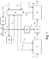
- FIG. 1 the block diagram of a particularly preferred embodiment of the invention is shown while the FIG. 2 shows a usable within the scope of the invention gasification device in longitudinal section.
- a hydrocarbon-containing feed 1 such as natural gas
- the preheater V which it leaves, preheated to a first temperature of about 380 ° C., via line 2 to be introduced into the sulfur separator S.
- contained sulfur is removed before the use is returned via line 3 in the preheater V and further heated there to a temperature of up to 650 ° C.
- an oxidizing agent 4 is preheated in the preheating V, which is then introduced parallel to the preheated hydrocarbon-containing insert 6 via line 5 in the gasification device P.
- the substances used are converted in the gasification device P to a hydrogen and carbon monoxide containing synthesis 8, which is supplied to the mixing device M at a temperature of more than 1000 ° C, mixed with a colder gas 9 to the reducing gas 10 and cooled to become.
- the reducing gas 10 is brought into contact with iron ore 11 in the reduction zone of the reduction device R, which is thereby reduced to iron 12.
- an exhaust gas 13 can be removed hot, which in addition to water and carbon dioxide also contains hydrogen and carbon monoxide, which were not reacted in the reduction.
- the hot exhaust gas 13 is cooled in the preheater V in indirect heat exchange with the sulfur-containing 1 and the desulfurized hydrocarbon-containing insert 3 and the oxidizing agent 4 and then led to the removal of solids via line 14 in the particle separation A.
- a first portion of the cooled and solids-cleaned exhaust gas 15 is exported via line 16 as fuel for a power plant, while a second portion 17 is passed via the recycle compressor B as a colder gas 9 in the mixing device M.
- gasification device P has a pressure-resistant, lined with a refractory ceramic K steel jacket S.
- the refractory ceramic K encloses the substantially cylindrical reaction space T, in whose lower region a catalyst bed C is arranged.
- a main burner H via which the preheated oxidizing agent 5, the likewise preheated hydrocarbon-containing insert 6 and steam 7 can be introduced into the reaction space T.
- the main burner H In addition to the main burner H is the with an electronic ignition device and a flame monitoring preheating burner D arranged. It serves to heat the gasification device P from the cold state and to maintain the operating temperature in a plant shutdown, being supplied via line 18 with an oxidizing agent and via line 19 with a fuel.
- the gasification device P forms a constructional unit with the mixing chamber M, in which the hot synthesis gas 8 produced with catalytic assistance is mixed with the cooler gas 9 for the reduction gas 10.
Landscapes
- Chemical & Material Sciences (AREA)
- Engineering & Computer Science (AREA)
- Organic Chemistry (AREA)
- Chemical Kinetics & Catalysis (AREA)
- Combustion & Propulsion (AREA)
- Health & Medical Sciences (AREA)
- General Health & Medical Sciences (AREA)
- Inorganic Chemistry (AREA)
- Manufacturing & Machinery (AREA)
- Materials Engineering (AREA)
- Metallurgy (AREA)
- Manufacture And Refinement Of Metals (AREA)
Abstract
Die Erfindung betrifft ein Verfahren sowie eine Vorrichtung zur Gewinnung eines Metalls (12), bei dem ein Oxid (11) des Metalls in einer Reduktionszone (R) mit einem Reduktionsgas (10) in Kontakt gebracht wird, zu dessen Erzeugung ein kohlenwasserstoffhaltiger Einsatz (6) mit einem Oxidationsmittel (5) im Reaktionsraum (T) einer Vergasungseinrichtung (P) durch Partialoxidation bei einem Druck, der weniger als 2bar über dem Betriebsdruck in der Reduktionszone (R) liegt, zu einem Kohlenmonoxid und Wasserstoff enthaltenden Syntheserohgas (8) umgesetzt wird. Kennzeichnend hierbei ist, dass der kohlenwasserstoffhaltige Einsatz (6) und/oder das Oxidationsmittel (5) stromaufwärts der Vergasungseinrichtung (P) durch Zuführung von bei der Reduktion des Metalloxids abfallender Wärme vorgewärmt werden.
Description
- Die Erfindung betrifft ein Verfahren zur Gewinnung eines Metalls, bei dem ein Oxid des Metalls in einer Reduktionszone mit einem Reduktionsgas in Kontakt gebracht wird, zu dessen Erzeugung ein kohlenwasserstoffhaltiger Einsatz mit einem Oxidationsmittel im Reaktionsraum einer Vergasungseinrichtung durch Partialoxidation bei einem Druck, der weniger als 2bar über dem Betriebsdruck in der Reduktionszone liegt, zu einem Kohlenmonoxid und Wasserstoff enthaltenden Syntheserohgas umgesetzt wird.
- Weiterhin betrifft die Erfindung eine Vorrichtung zur Durchführung des erfindungsgemäßen Verfahrens.
- Unter einem Oxidationsmittel ist im Rahmen der vorliegenden Erfindung ein Gasgemisch zu verstehen, das ungebundenen Sauerstoff enthält. Insbesondere gelten technisch reiner Sauerstoff, Luft oder mit Sauerstoff angereicherte Luft als Oxidationsmittel.
- Die Gewinnung von Metallen unter Einsatz eines durch Partialoxidation aus Kohlenwasserstoffen erzeugten Syntheserohgases als Reduktionsgas ist seit vielen Jahren Stand der Technik, wobei der Eisengewinnung durch Direktreduktion von Eisenerz die größte wirtschaftliche Bedeutung zukommt. Hierbei wird ein Reduktionsgas angestrebt, das neben einem für die Reduktion der Oxide geeigneten Druck und einer geeigneten Temperatur auch einen möglichst großen Anteil an den reduzierend wirkenden Stoffen Kohlenmonoxid und Wasserstoff aufweist. Um dies zu erreichen, werden grundsätzlich zwei Ansätze verfolgt.
- Bei dem ersten Ansatz wird die Partialoxidation bei einem hohen, zwischen 40 und 60bar liegenden Druck durchgeführt, um ein Syntheserohgas mit einem hohen Gehalt an reduzierend wirkenden Stoffen zu erhalten. Allerdings ist es dadurch erforderlich, das Syntheserohgas zu entspannen, um es als Reduktionsgas in die Reduktionszone einleiten zu können, in der ein wesentlich niedrigerer Druck herrscht, der im Falle der Eisengewinnung typischerweise zwischen 5 und 15bar liegt. Da die energetisch ohnehin ungünstige und mit großem apparativem Aufwand verbundene Entspannung technisch sinnvoll nur bei moderaten Temperaturen von weniger als 300°C realisiert werden kann, die Betriebstemperatur der Reduktionszone aber bei ca. 800°C liegt, ist eine erneute Anwärmung des Gases nach der Entspannung erforderlich.
- Der zweite Ansatz kommt ohne eine Entspannung des Syntheserohgases aus, weil die Partialoxidation bei einem Druck durchgeführt wird, der nur wenig über dem Betriebsdruck in der Reduktionszone liegt. Da jedoch die Ausbeute an Wasserstoff und Kohlenmonoxid mit dem Partialoxidationsdruck sinkt, weist das Syntheserohgas einen vergleichsweise geringen Gehalt an reduzierend wirkenden Stoffen auf, was eine Anreicherung dieser Stoffe bei der Erzeugung des Reduktionsgases erforderlich macht.
- Den zweiten Ansatz verfolgt beispielsweise die Patentschrift
US3907703 , in der ein Verfahren sowie eine Vorrichtung der gattungsgemäßen Art offenbart werden. Sie schlägt vor, aus dem aufgrund seiner Zusammensetzung und Temperatur nicht direkt als Reduktionsgas einsetzbaren Syntheserohgas durch Zumischung eines kälteren und weniger Wasser sowie Staub aufweisenden Synthesegases ein verbessertes Gasgemisch zu erzeugen, von dem ein erster Teil gekühlt und gewaschen wird, um das kältere Synthesegas zu erhalten, und ein zweiter Teil als Reduktionsgas in die Reduktionszone eingeleitet wird. Der für die Behandlung des Syntheserohgases erforderliche Aufwand ist erheblich und wirkt sich negativ auf die Wirtschaftlichkeit der Metallerzeugung aus. - Aufgabe der vorliegenden Erfindung ist es, ein Verfahren der gattungsgemäßen Art sowie eine Vorrichtung zu dessen Durchführung anzugeben, durch die es möglich ist, die Nachteile des Standes der Technik zu überwinden.
- Die gestellte Aufgabe wird verfahrensseitig erfindungsgemäß dadurch gelöst, dass der kohlenwasserstoffhaltige Einsatz und/oder das Oxidationsmittel stromaufwärts der Vergasungseinrichtung durch Zuführung von bei der Reduktion des Metalloxids abfallender Wärme vorgewärmt werden.
- Bei der Partialoxidation werden die eingesetzten Kohlenwasserstoffe unter Sauerstoffmangel mit oder ohne katalytische Unterstützung umgesetzt, wobei Kohlenmonoxid und Wasserstoff durch partielle Oxidation und Reformierung entstehen. Die Höhe der Ausbeute an Wasserstoff und Kohlenmonoxid wird nicht zuletzt durch die Notwendigkeit bestimmt, einen Teil der Kohlenwasserstoffe zur Deckung des Wärmebedarfs unter Bildung von Wasser und Kohlendioxid vollständig zu verbrennen.
- Durch die erfindungsgemäße Vorwärmung von einem oder mehreren Einsatzstoffen reicht es aus, zur Deckung des Wärmebedarfs der Partialoxidation einen im Vergleich zum Stand der Technik kleineren Teil der eingesetzten Kohlenwasserstoffe vollständig zu oxidieren, wodurch ein größerer Teil zu Wasserstoff und Kohlenmonoxid umgesetzt und ein Syntheserohgas mit einem erhöhten Anteil an reduzierend wirkenden Stoffen erhalten werden kann.
- Vorzugsweise erfolgt die Vorwärmung so, dass ein vorgewärmter Einsatzstoff mit einer Temperatur von bis 650°C in die Vergasungseinrichtung eingeleitet werden kann. Hierzu wird der Einsatzstoff beispielsweise in indirektem Wärmetausch gegen heiß aus der Reduktionszone strömendes Abgas aufgeheizt.
- Die Vorwärmung eines Einsatzstoffes kann ein- oder mehrstufig erfolgen. Wenn beispielsweise der kohlenwasserstoffhaltige Einsatz vor seiner Einleitung in die Vergasungseinrichtung adsorptiv entschwefelt wird, wofür seine Temperatur üblicherweise einen Wert von ca. 380°C nicht überschreiten darf, ist erfindungsgemäß vorgesehen, den kohlenwasserstoffhaltigen Einsatz in einem ersten Vorwärmschritt bis zur Entschwefelungstemperatur aufzuheizen und anschließend den entschwefelten kohlenwasserstoffhaltigen Einsatz in einem zweiten Schritt weiter vorzuwärmen.
- Das Syntheserohgas verlässt die Vergasungseinrichtung typischerweise mit einer Temperatur zwischen 1000 und 1400°C, weshalb es u. U. nicht direkt, sondern erst nach einer Abkühlung als Reduktionsgas mit Temperatur in die Reduktionszone eingeleitet werden kann, die im Falle der Direktreduktion von Eisenerz zwischen 750 und 1000°C liegen. Bevorzugt wird das Syntheserohgas zur Abkühlung mit einem kühleren Gas, bei dem es sich etwa um Stickstoff oder Wasserdampf handelt, gemischt. Vorzugsweise wird als kühleres Gas aber ein Rückführstrom aus dem Reduktionsprozess eingesetzt, wie beispielsweise ein Wasserstoff und/oder Kohlenmonoxid enthaltendes Abgas aus der Reduktionszone, das gegen einen oder mehrere der Einsatzstoffe für die Partialoxidation und/oder bei einer Dampfproduktion abgekühlt und anschließend von Feststoffpartikeln gereinigt wird. Nicht für die Abkühlung des Synthesegases benötigtes Abgas kann exportiert und etwa in einem Kraftwerk zur Stromerzeugung verfeuert werden.
- Wenn das kühlere Gas mit einem geringeren Druck vorliegt, als das abzukühlende Syntheserohgas, wie dies insbesondere der Fall ist, wenn als kühleres Gas ein Rückführstrom aus dem Reduktionsprozess eingesetzt wird, ist eine Verdichtung dieses Gases erforderlich. Diese Verdichtung kann mit einem mechanischen Verdichter durchgeführt werden. Vorzugsweise wird das kühlere Gas jedoch mit Hilfe eines Ejektors verdichtet, wobei das abzukühlende Syntheserohgas als Treibmedium dient.
- Das erfindungsgemäße Verfahren ist besonders zum Einsatz bei der Direktreduktion von Eisenerz geeignet. Daneben soll seine Verwendung bei der Reduktion anderer Metalloxide jedoch nicht ausgeschlossen sein.
- Das erfindungsgemäße Verfahren weiterbildend wird vorgeschlagen, zur Durchführung der Partialoxidation den kohlenwasserstoffhaltigen Einsatz zusammen mit dem Oxidationsmittel in den Reaktionsraum der Vergasungseinrichtung über einen Hauptbrenner einzubringen, der vorzugsweise einen bei Betriebsdruck der Vergasungseinrichtung betreibbaren Vorheizbrenner umfasst. Ein derartiger Hauptbrenner ist beispielsweise in der Patentanmeldung
WO2016192833 offenbart, deren Inhalt mit ihrer Zitierung in die vorliegende Beschreibung aufgenommen wird. Haupt-und Vorheizbrenner können jedoch auch als getrennte Apparate ausgeführt sein. - Mit Hilfe des Vorheizbrenners wird der gewöhnlich von einer feuerfesten Keramik begrenzte Reaktionsraum der Vergasungseinrichtung langsam und kontrolliert vom kalten Zustand auf Betriebstemperatur gebracht. Außerdem kann bei einer Unterbrechung der Synthesegaserzeugung, wie sie etwa bei einer Störung der Metalloxidreduktion notwendig ist, die Vergasungseinrichtung über den integrierten Vorheizbrenner bei Betriebsdruck auf Betriebstemperatur gehalten werden. Dadurch ist es möglich, die Syntheserohgasproduktion jederzeit wesentlich schneller wieder aufzunehmen, als im Stand der Technik, bei dem es erforderlich ist, zunächst den Vorheizbrenner aus der drucklosen Vergasungseinrichtung auszubauen, die anschließend erst auf Betriebsdruck gebracht werden kann.
- Vorzugsweise wir dem Vorheizbrenner bei seinem Betrieb ein Brenngas, das dem kohlenwasserstoffhaltigen Einsatz gleichen kann, sowie ein Oxidationsmittel mit Sauerstoffüberschuss zugeführt.
- Weiterhin betrifft die Erfindung eine Vorrichtung zur Gewinnung eines Metalls, mit einer Vergasungs- und eine Reduktionseinrichtung, wobei die Reduktionseinrichtung eine Reduktionszone aufweist, in der ein Oxid des Metalls mit einem Reduktionsgas in Kontakt gebracht werden kann, zu dessen Erzeugung ein kohlenwasserstoffhaltiger Einsatz mit einem Oxidationsmittel in der Vergasungseinrichtung durch Partialoxidation bei einem Druck, der weniger als 2bar über dem Betriebsdruck in der Reduktionszone liegt, zu einem Kohlenmonoxid und Wasserstoff enthaltenden Syntheserohgas umsetzbar ist.
- Die gestellte Aufgabe wird vorrichtungsseitig erfindungsgemäß dadurch gelöst, dass sie eine Vorwärmeinrichtung aufweist, in der der kohlenwasserstoffhaltige Einsatz und/oder das Oxidationsmittel stromaufwärts der Vergasungseinrichtung durch Zuführung von bei der Reduktion des Metalloxids abfallender Wärme vorgewärmt werden können.
- Bevorzugt ist die Vorwärmeinrichtung strömungstechnisch mit der Reduktionseinrichtung verbunden, so dass ein dort heiß anfallendes Abgas in die Vorwärmeinrichtung geführt und in indirektem Wärmetausch mit einem vorzuwärmenden Einsatzstoff für die Vergasungseinrichtung abgekühlt werden kann.
- Weiterhin bevorzugt umfasst die erfindungsgemäße Vorrichtung eine stromabwärts der Vergasungseinrichtung und stromaufwärts der Reduktionseinrichtung angeordnete Mischkammer, in der das Syntheserohgas mit einem kühleren Gas, bei dem es sich etwa um Stickstoff, Wasserdampf oder ein Rückführgas aus der Reduktionseinrichtung handelt, zum Reduktionsgas gemischt und abgekühlt werden kann. Zweckmäßigerweise ist die Mischeinrichtung mit der Vorwärmeinrichtung verbunden, so dass ihr als kühleres Gas ein dort gegen einen Einsatzstoff für die Vergasungseinrichtung abgekühltes Abgas aus der Reduktionseinrichtung zuführbar ist.
- Die Mischkammer kann als eigenständiges Anlagenteil ausgeführt sein oder mit einem anderen Anlagenteil eine bauliche Einheit bilden. Beispielsweise kann die Mischeinrichtung von dem druckfesten Außenmantel der Vergasungseinrichtung umschlossen sein.
- Zur Einleitung des kühleren Gases in die Mischkammer kann die erfindungsgemäße Vorrichtung einen Verdichter wie beispielsweise einen Kolben- oder Turboverdichter umfassen, mit dem der Druck des kühleren Gases auf den Druck in der Mischkammer angehoben werden kann. Bevorzugt ist jedoch die Mischkammer als Teil eines Ejektors ausgeführt, in dem das abzukühlende Syntheserohgas als Treibmedium einsetzbar ist, um das kühlere Gas anzusaugen.
- Bei der Vergasungseirichtung handelt es sich vorzugsweise um einen Reaktor mit einem Reaktionsraum, der von einer feuerfesten Keramik begrenzt wird, und in dem eine Partialoxidation mit oder ohne katalytische Unterstützung durchführbar ist. Zweckmäßigerweise umfasst die Vergasungseinrichtung einen Hauptbrenner zur Einleitung der Einsatzstoffe sowie einen bei dem Betriebsdruck der Vergasungseinrichtung betreibbaren, mit einer elektrischen Zündvorrichtung sowie einer Flammenüberwachung ausgestatteten Vorheizbrenner. Der Vorheizbrenner ist entweder in den Hauptbrenner integriert oder als eigenständiger Apparat ausgeführt. Zur Vermeidung von Beschädigungen der empfindlichen elektrischen Teile, kann insbesondere die Elektrode der Zündvorrichtung im Normalbetrieb der Vergasungseinrichtung in einen nur mäßig thermisch belasteten Bereich bewegt werden. Dies wird z. B. über ein Stopfbuchsensystem erreicht, über das die Elektrode in die feuerfeste Begrenzung des Reaktionsraums zurückgezogen werden kann.
- Im Folgenden soll die Erfindung anhand zweier in den
Figuren 1 und2 schematisch dargestellter Ausführungsbeispiele näher erläutert werden. - In der
Figur 1 ist das Blockdiagramm einer besonders bevorzugten Ausgestaltung der Erfindung dargestellt, während dieFigur 2 eine im Rahmen der Erfindung einsetzbare Vergasungseinrichtung im Längsschnitt zeigt. - In der
Figur 1 wird ein kohlenwasserstoffhaltiger Einsatz 1 wie etwa Erdgas der Vorwärmeinrichtung V zugeführt, die er, auf eine erste bei ca. 380°C liegende Temperatur vorgewärmt, über Leitung 2 verlässt, um in die Schwefelabtrennung S eingeleitet zu werden. Hier wird enthaltener Schwefel entfernt, ehe der Einsatz über Leitung 3 in die Vorwärmeinrichtung V zurückgeführt und dort weiter auf eine Temperatur von bis zu 650°C aufgeheizt wird. Ebenfalls wird in der Vorwärmeinrichtung V ein Oxidationsmittel 4 vorgewärmt, das anschließend parallel zum vorgewärmten kohlenwasserstoffhaltigen Einsatz 6 über Leitung 5 in die Vergasungseinrichtung P eingeleitet wird. Gemeinsam mit Dampf 7 werden die eingesetzten Stoffe in der Vergasungseinrichtung P zu einem Wasserstoff und Kohlenmonoxid enthaltenden Syntheserohgas 8 umgesetzt, das mit einer Temperatur von mehr als 1000°C der Mischeinrichtung M zugeführt wird, um mit einem kälteren Gas 9 zum Reduktionsgas 10 gemischt und abgekühlt zu werden. - Das Reduktionsgas 10 wird in der Reduktionszone der Reduktionseinrichtung R mit Eisenerz 11 in Kontakt gebracht, das dabei zu Eisen 12 reduziert wird. Aus der Reduktionseinrichtung R kann ein Abgas 13 heiß abgezogen werden, das neben Wasser und Kohlendioxid auch Wasserstoff und Kohlenmonoxid enthält, die bei der Reduktion nicht umgesetzt wurden. Das heiße Abgas 13 wird in der Vorwärmeinrichtung V in indirektem Wärmetausch gegen den schwefelhaltigen 1 und den entschwefelten kohlenwasserstoffhaltigen Einsatz 3 sowie das Oxidationsmittel 4 abgekühlt und anschließend zur Entfernung von Feststoffen über Leitung 14 in die Partikelabtrennung A geführt. Ein erster Teil des abgekühlten und von Feststoffen gereinigten Abgases 15 wird über Leitung 16 etwa als Brennstoff für ein Kraftwerk exportiert, während ein zweiter Teil 17 über den Rückführverdichter B als kälteres Gas 9 in die Mischeinrichtung M geleitet wird.
- Die in
Figur 2 dargestellte Vergasungseinrichtung P weist einen druckfesten, mit einer feuerfesten Keramik K ausgekleideten Stahlmantel S auf. Die feuerfeste Keramik K umschließt den im Wesentlichen zylindrischen Reaktionsraum T, in dessen unterem Bereich ein Katalysatorbett C angeordnet ist. Am Kopf der Vergasungseinrichtung P befindet sich ein Hauptbrenner H, über den das vorgewärmte Oxidationsmittel 5, der ebenfalls vorgewärmte kohlenwasserstoffhaltige Einsatz 6 sowie Dampf 7 in den Reaktionsraum T eingebracht werden können. Neben dem Hauptbrenner H ist der mit einer elektronischen Zündvorrichtung sowie einer Flammenüberwachung ausgestattete Vorheizbrenner D angeordnet. Er dient zur Aufheizung der Vergasungseinrichtung P aus dem kalten Zustand und zur Aufrechterhaltung der Betriebstemperatur bei einem Anlagenstillstand, wobei er über Leitung 18 mit einem Oxidationsmittel und über Leitung 19 mit einem Brennstoff versorgt wird. Er ist bei Betriebsdruck betreibbar und muss während des Normalbetriebs der Vergasungseinrichtung P nicht ausgebaut werden. Um insbesondere die elektronische Zündeinrichtung unter den Bedingungen des Normalbetriebs vor Beschädigungen zu schützen, kann die Zündelektrode Z bis in die feuerfeste Keramik K zurückgezogen werden. Die Vergasungseinrichtung P bildet mit der Mischkammer M, in der das mit katalytischer Unterstützung erzeugte heiße Syntheserohgas 8 mit dem kühleren Gas 9 zum Reduktionsgas 10 gemischt wird, eine bauliche Einheit.
Claims (12)
- Verfahren zur Gewinnung eines Metalls (12), bei dem ein Oxid (11) des Metalls in einer Reduktionszone (R) mit einem Reduktionsgas (10) in Kontakt gebracht wird, zu dessen Erzeugung ein kohlenwasserstoffhaltiger Einsatz (6) mit einem Oxidationsmittel (5) im Reaktionsraum (T) einer Vergasungseinrichtung (P) durch Partialoxidation bei einem Druck, der weniger als 2bar über dem Betriebsdruck in der Reduktionszone (R) liegt, zu einem Kohlenmonoxid und Wasserstoff enthaltenden Syntheserohgas (8) umgesetzt wird, dadurch gekennzeichnet, dass der kohlenwasserstoffhaltige Einsatz (6) und/oder das Oxidationsmittel (5) stromaufwärts der Vergasungseinrichtung (P) durch Zuführung von bei der Reduktion des Metalloxids abfallender Wärme vorgewärmt werden.
- Verfahren nach Anspruch 1, dadurch gekennzeichnet, dass ein Einsatzsoff (5, 6) bis auf maximal 650°C vorgewärmt wird.
- Verfahren nach einem der Ansprüche 1 oder 2, dadurch gekennzeichnet, dass Syntheserohgas (8) mit einem kühleren Gas (9) zum Reduktionsgas (10) gemischt wird.
- Verfahren nach Anspruch 3, dadurch gekennzeichnet, dass als kühleres Gas (9) Stickstoff oder Wasserdampf oder ein von Feststoffpartikeln gereinigtes Abgas (13) aus der Reduktionszone (R) eingesetzt wird.
- Verfahren nach einem der Ansprüche 3 oder 4, dadurch gekennzeichnet, dass das kühlere Gas (9) mit Hilfe eines Ejektors verdichtet wird.
- Verfahren nach einem der Ansprüche 1 bis 5, dadurch gekennzeichnet, dass es bei der Direktreduktion von Eisenerz eingesetzt wird.
- Vorrichtung zur Gewinnung eines Metalls (12), mit einer Vergasungs- (P) und einer Reduktionseinrichtung (R), wobei die Reduktionseinrichtung (R) eine Reduktionszone aufweist, in der ein Oxid (11) des Metalls (12) mit einem Reduktionsgas (10) in Kontakt gebracht werden kann, zu dessen Erzeugung ein kohlenwasserstoffhaltiger Einsatz (6) mit einem Oxidationsmittel (5) in der Vergasungseinrichtung (P) durch Partialoxidation bei einem Druck, der weniger als 2bar über dem Betriebsdruck in der Reduktionszone (R) liegt, zu einem Kohlenmonoxid und Wasserstoff enthaltenden Syntheserohgas (8) umsetzbar ist, dadurch gekennzeichnet, dass sie eine Vorwärmeinrichtung (V) aufweist, in der der kohlenwasserstoffhaltige Einsatz (6) und/oder das Oxidationsmittel (5) stromaufwärts der Vergasungseinrichtung (P) durch Zuführung von bei der Reduktion des Metalloxids abfallender Wärme vorgewärmt werden können.
- Vorrichtung nach Anspruch 7, dadurch gekennzeichnet, dass die Vorwärmeinrichtung (V) strömungstechnisch so mit der Reduktionseinrichtung (R) verbunden ist, dass ein dort heiß anfallendes Abgas (13) in die Vorwärmeinrichtung (V) geführt und in indirektem Wärmetausch mit einem vorzuwärmenden Einsatzstoff (1, 4) für die Vergasungseinrichtung (P) abgekühlt werden kann.
- Vorrichtung nach einem der Ansprüche 7 oder 8, dadurch gekennzeichnet, dass sie eine stromabwärts der Vergasungseinrichtung (P) und stromaufwärts der Reduktionseinrichtung (R) angeordnete Mischkammer (M) umfasst, in der Syntheserohgas (8) mit einem kühleren Gas (9) zum Reduktionsgas (10) gemischt und abgekühlt werden kann.
- Vorrichtung nach Anspruch 9, dadurch gekennzeichnet, dass die Mischkammer (M) als eigenständiges Anlagenteil ausgeführt ist oder mit einem anderen Anlagenteil (P) eine bauliche Einheit bildet.
- Vorrichtung nach einem der Ansprüche 9 oder 10, dadurch gekennzeichnet, dass die Mischkammer (M) als Teil eines Ejektors ausgeführt ist, in dem das abzukühlende Syntheserohgas (8) als Treibmedium einsetzbar ist, um das kühlere Gas (9) anzusaugen.
- Vorrichtung nach einem der Ansprüche 7 bis 11, dadurch gekennzeichnet, dass die Vergasungseinrichtung (V) einen Hauptbrenner (H) zur Einleitung der Einsatzstoffe (5, 6) sowie einen bei dem Betriebsdruck der Vergasungseinrichtung (P) betreibbaren, mit einer elektrischen Zündvorrichtung und einer Flammenüberwachung ausgestatteten Vorheizbrenner (D) umfasst.
Applications Claiming Priority (1)
| Application Number | Priority Date | Filing Date | Title |
|---|---|---|---|
| DE102017009097.1A DE102017009097A1 (de) | 2017-09-28 | 2017-09-28 | Verfahren und Vorrichtung zur Reduktion von Metalloxiden |
Publications (1)
| Publication Number | Publication Date |
|---|---|
| EP3461919A1 true EP3461919A1 (de) | 2019-04-03 |
Family
ID=60856829
Family Applications (1)
| Application Number | Title | Priority Date | Filing Date |
|---|---|---|---|
| EP17020554.6A Withdrawn EP3461919A1 (de) | 2017-09-28 | 2017-11-30 | Verfahren und vorrichtung zur reduktion von metalloxiden |
Country Status (3)
| Country | Link |
|---|---|
| EP (1) | EP3461919A1 (de) |
| DE (1) | DE102017009097A1 (de) |
| WO (1) | WO2019063128A1 (de) |
Citations (4)
| Publication number | Priority date | Publication date | Assignee | Title |
|---|---|---|---|---|
| US3907703A (en) | 1971-12-23 | 1975-09-23 | Texaco Development Corp | Process for producing reducing gas |
| US3951644A (en) * | 1974-05-06 | 1976-04-20 | Heatran, Inc. | Method of producing iron and steel from iron ore |
| US20150345869A1 (en) * | 2009-07-31 | 2015-12-03 | Siemens Vai Metals Technologies Gmbh | REFORMER GAS-BASED REDUCING METHOD WITH REDUCED NOx EMISSION |
| WO2016192833A1 (de) | 2015-05-29 | 2016-12-08 | Linde Aktiengesellschaft | Prozessbrenner und verfahren zum betreiben eines reaktors mit einem prozessbrenner |
-
2017
- 2017-09-28 DE DE102017009097.1A patent/DE102017009097A1/de not_active Withdrawn
- 2017-11-30 EP EP17020554.6A patent/EP3461919A1/de not_active Withdrawn
-
2018
- 2018-09-26 WO PCT/EP2018/025246 patent/WO2019063128A1/de not_active Ceased
Patent Citations (4)
| Publication number | Priority date | Publication date | Assignee | Title |
|---|---|---|---|---|
| US3907703A (en) | 1971-12-23 | 1975-09-23 | Texaco Development Corp | Process for producing reducing gas |
| US3951644A (en) * | 1974-05-06 | 1976-04-20 | Heatran, Inc. | Method of producing iron and steel from iron ore |
| US20150345869A1 (en) * | 2009-07-31 | 2015-12-03 | Siemens Vai Metals Technologies Gmbh | REFORMER GAS-BASED REDUCING METHOD WITH REDUCED NOx EMISSION |
| WO2016192833A1 (de) | 2015-05-29 | 2016-12-08 | Linde Aktiengesellschaft | Prozessbrenner und verfahren zum betreiben eines reaktors mit einem prozessbrenner |
Also Published As
| Publication number | Publication date |
|---|---|
| WO2019063128A1 (de) | 2019-04-04 |
| DE102017009097A1 (de) | 2019-03-28 |
Similar Documents
| Publication | Publication Date | Title |
|---|---|---|
| EP4363372A1 (de) | Verfahren und vorrichtung zur erzeugung von wasserstoff aus ammoniak | |
| EP2459754B1 (de) | Reformergasbasiertes reduktionsverfahren mit rückführung der reduktionsabgase und decarbonisierung des abgasteils verwendet als brenngas für den reformer | |
| EP2751294B1 (de) | Verfahren zur aufbereitung von abgasen aus anlagen zur roheisenherstellung | |
| EP4363371A1 (de) | Verfahren und vorrichtung zur erzeugung von wasserstoff aus ammoniak | |
| DE4437679C3 (de) | Verfahren und Anlage zur Verarbeitung von eisenhaltigen Metalloxiden | |
| AT505401B1 (de) | Verfahren zum erschmelzen von roheisen unter rückführung von gichtgas unter zusatz von kohlenwasserstoffen | |
| EP2714942B1 (de) | Reduktion von metalloxiden unter verwendung eines sowohl kohlenwasserstoff als auch wasserstoff enthaltenden gasstromes | |
| DE1783180B2 (de) | Verfahren zur gasfoermigen reduktion von eisenerzen und vorrichtung zur durchfuehrung dieses verfahrens | |
| AT507632A1 (de) | Verfahren und vorrichtung zur erzeugung eines syntheserohgases | |
| DE112005001881T5 (de) | Verfahren und Vorrichtung zum Herstellen von reinen reduzierenden Gasen aus Koksofengas | |
| WO2018108323A1 (de) | Verfahren zur wärmerückgewinnung aus einem von einem brenner erzeugten rauchgas | |
| EP3736347A1 (de) | Nutzung von sauerstoff aus wasserelektrolyse bei der eisen- und/oder stahlerzeugung | |
| DE2659782A1 (de) | Verfahren zur weiterverarbeitung von koksofengas | |
| DE102022125987B4 (de) | Verfahren und Vorrichtung zur Erzeugung von Wasserstoff aus kohlenwasserstoffhaltigen Gasgemischen | |
| EP3541964A1 (de) | Vefahren und vorrichtung zum betreiben eines direktreduktionsreaktors zur herstellung von direktreduziertem eisen aus eisenerz | |
| WO2019063128A1 (de) | Verfahren und vorrichtung zur reduktion von metalloxiden | |
| EP2738268A1 (de) | Verfahren zur Reduktion von Metalloxiden zu metallisiertem Material in einem Direktreduktionsprozess. | |
| DE102016103321B4 (de) | Vorrichtung und Verfahren zur Dampfreformierung | |
| EP2746408A1 (de) | Überhitzung von einem in einem Reduktionsprozess genutzten Exportgas zum Ausgleich von Mengenschwankungen und Vorrichtung zum dessen | |
| DE102011002612A1 (de) | Verfahren zur Behandlung eines kohlendioxidhaltigen Abgases | |
| EP0108198A2 (de) | Verfahren zum Betreiben eines Reaktors zur Erzeugung von Synthesegas und Vorrichtung zur Durchführung des Verfahrens | |
| EP2650385A1 (de) | Verfahren und Vorrichtung zur Herstellung von flüssigem Roheisen und/oder von Eisenschwamm | |
| DE102023108158A1 (de) | Verfahren zum Betreiben einer Direktreduktionsanlage | |
| DE102013213528A1 (de) | Reformersystem zur Verbrennung von Restgas in einem Dampfreformer | |
| DE102023005468B4 (de) | Vorrichtung und Verfahren zur Erzeugung von Wasserstoff- und Kohlenstoffdioxid-Produktströmen |
Legal Events
| Date | Code | Title | Description |
|---|---|---|---|
| PUAI | Public reference made under article 153(3) epc to a published international application that has entered the european phase |
Free format text: ORIGINAL CODE: 0009012 |
|
| AK | Designated contracting states |
Kind code of ref document: A1 Designated state(s): AL AT BE BG CH CY CZ DE DK EE ES FI FR GB GR HR HU IE IS IT LI LT LU LV MC MK MT NL NO PL PT RO RS SE SI SK SM TR |
|
| AX | Request for extension of the european patent |
Extension state: BA ME |
|
| STAA | Information on the status of an ep patent application or granted ep patent |
Free format text: STATUS: THE APPLICATION IS DEEMED TO BE WITHDRAWN |
|
| 18D | Application deemed to be withdrawn |
Effective date: 20191005 |