EP3461735B1 - Unidirektionaler drehmomentverstärkungspropeller - Google Patents
Unidirektionaler drehmomentverstärkungspropeller Download PDFInfo
- Publication number
- EP3461735B1 EP3461735B1 EP17020537.1A EP17020537A EP3461735B1 EP 3461735 B1 EP3461735 B1 EP 3461735B1 EP 17020537 A EP17020537 A EP 17020537A EP 3461735 B1 EP3461735 B1 EP 3461735B1
- Authority
- EP
- European Patent Office
- Prior art keywords
- propeller
- shaft
- adapter
- hub
- axial direction
- Prior art date
- Legal status (The legal status is an assumption and is not a legal conclusion. Google has not performed a legal analysis and makes no representation as to the accuracy of the status listed.)
- Active
Links
Images


Classifications
-
- B—PERFORMING OPERATIONS; TRANSPORTING
- B63—SHIPS OR OTHER WATERBORNE VESSELS; RELATED EQUIPMENT
- B63H—MARINE PROPULSION OR STEERING
- B63H1/00—Propulsive elements directly acting on water
- B63H1/02—Propulsive elements directly acting on water of rotary type
- B63H1/12—Propulsive elements directly acting on water of rotary type with rotation axis substantially in propulsive direction
- B63H1/14—Propellers
- B63H1/28—Other means for improving propeller efficiency
-
- B—PERFORMING OPERATIONS; TRANSPORTING
- B63—SHIPS OR OTHER WATERBORNE VESSELS; RELATED EQUIPMENT
- B63H—MARINE PROPULSION OR STEERING
- B63H1/00—Propulsive elements directly acting on water
- B63H1/02—Propulsive elements directly acting on water of rotary type
- B63H1/12—Propulsive elements directly acting on water of rotary type with rotation axis substantially in propulsive direction
- B63H1/14—Propellers
- B63H1/20—Hubs; Blade connections
-
- B—PERFORMING OPERATIONS; TRANSPORTING
- B63—SHIPS OR OTHER WATERBORNE VESSELS; RELATED EQUIPMENT
- B63H—MARINE PROPULSION OR STEERING
- B63H23/00—Transmitting power from propulsion power plant to propulsive elements
- B63H23/32—Other parts
- B63H23/34—Propeller shafts; Paddle-wheel shafts; Attachment of propellers on shafts
-
- F—MECHANICAL ENGINEERING; LIGHTING; HEATING; WEAPONS; BLASTING
- F16—ENGINEERING ELEMENTS AND UNITS; GENERAL MEASURES FOR PRODUCING AND MAINTAINING EFFECTIVE FUNCTIONING OF MACHINES OR INSTALLATIONS; THERMAL INSULATION IN GENERAL
- F16D—COUPLINGS FOR TRANSMITTING ROTATION; CLUTCHES; BRAKES
- F16D41/00—Freewheels or freewheel clutches
- F16D41/18—Freewheels or freewheel clutches with non-hinged detent
- F16D41/185—Freewheels or freewheel clutches with non-hinged detent the engaging movement having an axial component
-
- B—PERFORMING OPERATIONS; TRANSPORTING
- B63—SHIPS OR OTHER WATERBORNE VESSELS; RELATED EQUIPMENT
- B63H—MARINE PROPULSION OR STEERING
- B63H1/00—Propulsive elements directly acting on water
- B63H1/02—Propulsive elements directly acting on water of rotary type
- B63H1/12—Propulsive elements directly acting on water of rotary type with rotation axis substantially in propulsive direction
- B63H1/14—Propellers
- B63H1/28—Other means for improving propeller efficiency
- B63H2001/283—Propeller hub caps with fins having a pitch different from pitch of propeller blades, or a helix hand opposed to the propellers' helix hand
-
- B—PERFORMING OPERATIONS; TRANSPORTING
- B63—SHIPS OR OTHER WATERBORNE VESSELS; RELATED EQUIPMENT
- B63H—MARINE PROPULSION OR STEERING
- B63H5/00—Arrangements on vessels of propulsion elements directly acting on water
- B63H5/07—Arrangements on vessels of propulsion elements directly acting on water of propellers
- B63H5/08—Arrangements on vessels of propulsion elements directly acting on water of propellers of more than one propeller
- B63H5/10—Arrangements on vessels of propulsion elements directly acting on water of propellers of more than one propeller of coaxial type, e.g. of counter-rotative type
- B63H2005/106—Arrangements on vessels of propulsion elements directly acting on water of propellers of more than one propeller of coaxial type, e.g. of counter-rotative type with drive shafts of second or further propellers co-axially passing through hub of first propeller, e.g. counter-rotating tandem propellers with co-axial drive shafts
Definitions
- the present invention relates to a turbo propeller device which ensures coordination between a marine vessel propeller and torque of a shaft rotating same and which automatically increases shaft torque.
- a marine vessel is impelled in the sea by a propeller which is attached to the engine from one end and to the other end of a shaft connected to a transmission.
- the extent of the shaft torque is substantially influential on the movement capacity of the marine vessel, since it accelerates the propeller.
- the output torque of the shaft is a function of engine power, speed and transmission reduction.
- shaft torque may not be at a satisfactory level for the thrust expected from the propeller. This is referred to as "heavy" propeller in that the engine may not reach to the highest revolution power and figures, and for some, even some % missing engine revolution may be acceptable, which means an increase in fuel costs and wear of the engine.
- the dual propeller structure is essentially based on the principle that the torque that is received from the shaft connected with the engine is transferred to a second shaft, with which the front propeller is communicated by means of a first power transfer means (for instance a gear wheel mechanism), and that the torque that is received from the shaft connected with the motor is transferred to a third shaft that is coaxial with the second shaft, the third shaft being communicated with the rear propeller by means of the second power transfer means.
- a first power transfer means for instance a gear wheel mechanism
- An exemplary arrangement for a dual propeller structure is disclosed in US 6,821,169 .
- US 6,702,631 and US 6,478,641 disclose a dual propeller structure.
- the resultant thrust slightly increases as the torque that is necessary for rotating both propellers is provided by one power source, by the shaft communicated with the engine. This is because of the fact that two separate propeller devices entail two separate sources of energy loss. Thus, each propeller device has its own power transfer means, and they cause significant mechanical losses. Moreover, the rear propeller uses the water which has already been de-energized by the front propeller, causing a loss of efficiency.
- US 14/460923 of the present inventor describes a turbo propeller system which is locked in one direction dependent on engine shaft carrying the main propeller and rotates freely on the other direction.
- Turbo propeller is mounted with bearings that are locked in one direction and being free to rotate in the other direction.
- second propeller bearings are locked and water rotates the second propeller with a new, calculated pitch and provides extra torque gain to the main shaft.
- turbo propeller rotates idly.
- the adaption of the solution proposed in US 14/460923 to a conventional propeller that is already in use may involve relative challenges.
- KR 2015 0056192 A discloses a propeller system which is locked in one direction and rotates freely on the other direction.
- propellers known as "Grim wheel” or “Vane wheel”.
- the rear propeller has, in general, a larger diameter than that of the front propeller and while the inner part of the rear propeller acts mainly as a turbine, and the outer part has a thrusting function.
- Grim or Vane wheel propellers do not provide any torque contribution to the shaft, and they just provide contribution to the thrust.
- Another object of the present invention is to provide a propeller adaptable to conventional propellers which can increase shaft torque automatically with water leaving the front propeller.
- the present invention relates to a propeller device comprising a main shaft communicated from one end to a marine vessel engine transmission; a front propeller provided on the main shaft, the front propeller having a hub and a plurality of blades extending radially outwardly from the hub; a rear propeller being co-axially to and spaced apart from the front propeller backwardly in an axial direction, the rear propeller having a hub and a plurality of blades extending radially outwardly from the hub.
- the device further comprises an adaptor being coaxial with the main shaft and comprising a second shaft for supporting the rear propeller and a plurality of pitched-formed seating surfaces having ramps, the seating surfaces being spaced apart from the second shaft in axial direction, and the adaptor communicated with the rear side of the front propeller in the axial direction; a plurality of locking elements resiliently movable in the axial direction, each being in contact with the seating surfaces of the said adaptor from one end and communicated with the rear propeller from the other end.
- each locking element goes up from the ramps of the pitches and skips to the next pitch and rotates the rear propeller in the reverse direction with respect to the front propeller. In other words, in the rearward movement of the vessel, the rear propeller remains free relative to the front propeller in terms of direction of rotation.
- the rear propeller may be attached to a conventional propeller that is already in use and ensures the coordination between the front propeller and shaft torque and provides a gain of torque for the shaft.
- the invention is also directed to a marine vessel including a propeller device according to the invention.
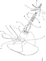
- the propeller system comprises a front propeller (1) and a rear propeller (34) arranged coaxially thereto.
- the front propeller (1) has a front propeller hub (2) and a plurality of front propeller blades (3) extending radially outwardly.
- the rear propeller (34) has a rear propeller hub (4) and a plurality of rear propeller blades (5) extending radially outwardly.
- the front propeller (1) has a shaft hole (8) at the center and a main shaft which is, at one end, attached to the vessel engine (not shown) is passed through the shaft hole (8) and fixed rigidly.
- An adapter (7) is attached from the hub to the back side (that side without engine) of front propeller (1).
- the adapter (7) has a cylindrical form, the lateral surfaces of which are tapered in the flow direction of water in order to decrease water resistance.
- a plurality of front propeller bolt connecting slots (9) are made on the back face surface of the front propeller hub (2) for connecting the front propeller (1) and the adapter (7).
- the adapter (7) has bolt connecting slots (10) formed circumferentially and extending in the axial direction, which are tightened and joined by means of the adapter-front propeller connecting bolts (11) after they are aligned with the front propeller connecting bolt slots (9).
- the propeller device according to the invention may be easily adapted to a conventional propeller.
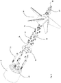
- the adapter (7) comprises a second shaft (6) on its back side, i.e. the side facing toward the rear propeller (34).
- Said second shaft (6) is preferably integral with the adapter (7), but optionally it may be arranged independently.
- the rear propeller (34) is supported rotationally on the second shaft (6) by means of a second shaft bearing (25).
- a first sealing member (23) is provided on the front side of the shaft bearing (25) and a second sealing member (24) is provided on the back side thereof.
- the tip of the second shaft (6) is threaded and a clamping bolt (27) is passed through the rear propeller end opening (35) and is engaged and tightened to said threads.
- the second shaft (6) and the rear propeller (34) are therefore connected.
- the lower part of the clamping bolt (27) rests on the base of the rear propeller end opening (35) when this bolt is tightened. Due to its construction, a washer (26) may be placed between the second sealing member (24) and the clamping bolt (27), and a ring (28) may be placed on the back side of the clamping bolt (27).
- pitches (29) spaced apart from the second shaft (6) in the axial direction.
- These pitches (29) are provided in circular shape around the axis and each pitch has a ramped/inclined seating surface (32).
- Each pitch (29) has a back surface (30) extending in axial direction.
- the pitch has a form such that the upper end of the back surface (31) is rounded. That section starting from the upper end of the pitch back surface (31) and moving downward from the inclined seating surface (32) toward the back surface of the next pitch is front surface of the pitch (36), which also has a rounded form.
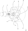
- the device according to the invention comprises a plurality of locking elements (18), one end of which is communicated with the rear propeller (34) and the other end of which is communicated with adapter seating surfaces (32).
- the locking elements (18) has a form similar to human finger and those parts that are communicated with seating surfaces (32), i.e. contact ends (33), have a rounded form.
- the locking elements (18) are through holes in axial direction, each of which is provided with a pin (20).
- a spring (19) is placed between the head of each pin (20) and the upper end of the locking element (18).
- the pins (20) are placed in the pin housings (37) formed on the rear propeller hub (4) surface facing to the adapter.
- a stud (21) exerts pressure on the upper part of each pin (20) head. These studs (21) are inserted through the stud holes (22) formed in axial direction on the rear propeller (34) end and are screwed and fixed to the threads formed within the holes.
- the upper end of the locking elements (18) is located in the pin housings (37).
- the locking elements (18) are formed such that axial movement of each locking element within pin housing (37) is possible.
- a disc (12) is connected to the surface of the rear propeller hub (4) facing to the adapter (7).
- a disc shaft hole (13) is provided on the center of the disc (12) for the passage of the second shaft (12), as well as a plurality of disc bolt connecting holes (14) formed circularly at that part close to the outer diameter of the disc.
- a plurality of disc connecting bolts (16) are passed through said holes, which are similarly passed through the aligned holes formed at the rear propeller hub (4) and tightened, thereby connection being provided.
- the disc (12) also comprises disc locking element holes (17) that are formed circularly and allow the locking elements to pass therethrough.
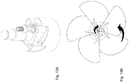
- FIG 8A and Figure 10B in forward movement of the vessel, the front propeller (1) and the rear propeller (34) rotate in the same direction.
- a representative locking element is positioned on the uppermost part of respective seating surface.
- the front propeller (1) follows the locking element seating surface due to the spring (19) as it rotates clockwise according to the figure ( Figure 9A ) and abuts against the back surface (30) of the next pitch and since it cannot move further, locking is achieved ( Figure 10A ).
- the front propeller (1) and the rear propeller (34) rotate in the same direction.
Landscapes
- Engineering & Computer Science (AREA)
- Mechanical Engineering (AREA)
- Chemical & Material Sciences (AREA)
- Combustion & Propulsion (AREA)
- Ocean & Marine Engineering (AREA)
- General Engineering & Computer Science (AREA)
- Structures Of Non-Positive Displacement Pumps (AREA)
- Other Liquid Machine Or Engine Such As Wave Power Use (AREA)
- Shafts, Cranks, Connecting Bars, And Related Bearings (AREA)
Claims (8)
- Propellervorrichtung, umfassend: eine Hauptwelle, die mit einem Ende mit einem Motorgetriebe eines Wasserfahrzeugs verbunden ist; einen vorderen Propeller (1), der an der Hauptwelle bereitgestellt ist, wobei der vordere Propeller (1), eine Nabe (2) und eine Vielzahl von Schaufeln (3) aufweist, die sich von der Nabe (2) radial auswärts erstrecken; einen hinteren Propeller (34), der koaxial zum vorderen Propeller (1) ist und in einer axialen Richtung nach hinten von diesem beabstandet ist, wobei der hintere Propeller (34) eine Nabe (4) und eine Vielzahl von Schaufeln (5) aufweist, die sich von der Nabe (4) radial auswärts erstrecken, wobei die Propellervorrichtung ferner einen Adapter (7) umfasst, der koaxial zur Hauptwelle ist und eine zweite Welle (6) zum Tragen des hinteren Propellers (34) umfasst, dadurch gekennzeichnet, dass der Adapter (7) eine Vielzahl von als Steigungen ausgebildeten Sitzflächen (32) mit Rampen aufweist, wobei die Sitzflächen (32) von der zweiten Welle (6) in axialer Richtung beabstandet sind und der Adapter (7) in der axialen Richtung mit der Rückseite des vorderen Propellers (1) verbunden ist; eine Vielzahl von Rastelementen (18), die in der axialen Richtung elastisch bewegbar sind und jeweils mit einem Ende mit den Sitzflächen (32) des Adapters (7) in Kontakt stehen und mit dem anderen Ende mit dem hinteren Propeller (34) verbunden sind.
- Vorrichtung nach Anspruch 1, dadurch gekennzeichnet, dass jede Steigung eine hintere Oberfläche (30) umfasst, die sich in axialer Richtung erstreckt und an der das Verrastungselement (18) anstößt.
- Vorrichtung nach Anspruch 2, dadurch gekennzeichnet, dass das obere Ende (31) der hinteren Oberfläche (30) der Steigung eine abgerundete Form aufweist.
- Vorrichtung nach Anspruch 3, dadurch gekennzeichnet, dass jede Steigung eine vordere Oberfläche (36) umfasst, die an der Vorderseite ihrer hinteren Oberfläche (30) positioniert ist und die eine gerundete Form aufweist.
- Vorrichtung nach Anspruch 1, dadurch gekennzeichnet, dass jedes Verrastungselement (18) einen Zapfen (20) umfasst, der in seiner axialen Richtung einführbar ist und eine Feder (19) umfasst, die jeweils zwischen Zapfen (20) und Verrastungselement (18) platziert ist.
- Vorrichtung nach Anspruch 5, dadurch gekennzeichnet, dass sie Zapfengehäuse (37) zum Einführen der jeweiligen Zapfen (20) aufweist, die an der hinteren Propellernabe (4) ausgebildet sind.
- Vorrichtung nach einem der vorangehenden Ansprüche, dadurch gekennzeichnet, dass die Vorrichtung an einen herkömmlichen Propeller anpassbar ist.
- Wasserfahrzeug, dadurch gekennzeichnet, dass es eine Vorrichtung nach einem der vorangehenden Ansprüche umfasst.
Applications Claiming Priority (1)
| Application Number | Priority Date | Filing Date | Title |
|---|---|---|---|
| TR2017/14615A TR201714615A2 (tr) | 2017-09-29 | 2017-09-29 | Gi̇zleni̇r düşey eksenli̇ pervane terti̇bati |
Publications (2)
| Publication Number | Publication Date |
|---|---|
| EP3461735A1 EP3461735A1 (de) | 2019-04-03 |
| EP3461735B1 true EP3461735B1 (de) | 2019-09-25 |
Family
ID=60021860
Family Applications (1)
| Application Number | Title | Priority Date | Filing Date |
|---|---|---|---|
| EP17020537.1A Active EP3461735B1 (de) | 2017-09-29 | 2017-11-20 | Unidirektionaler drehmomentverstärkungspropeller |
Country Status (3)
| Country | Link |
|---|---|
| US (1) | US10710687B2 (de) |
| EP (1) | EP3461735B1 (de) |
| TR (1) | TR201714615A2 (de) |
Families Citing this family (3)
| Publication number | Priority date | Publication date | Assignee | Title |
|---|---|---|---|---|
| FI130447B (en) * | 2020-12-18 | 2023-09-05 | Aker Arctic Tech Oy | Propeller |
| TW202438390A (zh) * | 2023-01-13 | 2024-10-01 | 美商艾羅維羅門特股份有限公司 | 垂直起降螺旋槳配接器及方法 |
| ES3021109A1 (es) * | 2023-11-23 | 2025-05-26 | Abal Pablo Alfonso Gonzalez | Hélice toroidal para embarcaciones |
Family Cites Families (8)
| Publication number | Priority date | Publication date | Assignee | Title |
|---|---|---|---|---|
| US4117652A (en) * | 1976-09-30 | 1978-10-03 | The J. B. Foote Foundry Co. | Transmission for self-propelled, walking lawn mowers |
| US6478641B2 (en) | 2000-01-20 | 2002-11-12 | W. Bishop Jordan | Transmission for driving counter-rotating propellers, lubrication system, and associated methods |
| US20030070407A1 (en) * | 2001-09-27 | 2003-04-17 | R. Mcdonner Orville | Self-propelled walk-behind string trimmer |
| US7661329B2 (en) * | 2005-05-06 | 2010-02-16 | Conntechnical Industries, Inc. | Pawl drive for coupling torque between two rotatable elements |
| KR20110116946A (ko) * | 2010-04-20 | 2011-10-26 | 경종만 | 선박의 에너지 효율 향상장치 |
| KR20150056192A (ko) * | 2013-11-15 | 2015-05-26 | 이경완 | 터빈을 이용한 프로펠러 효율 향상 장치 |
| JP6112097B2 (ja) * | 2013-11-25 | 2017-04-12 | トヨタ自動車株式会社 | 4輪駆動車両のディスコネクト機構付左右駆動力配分ユニット |
| EP2962931B1 (de) | 2014-06-20 | 2019-04-24 | Mehmet Nevres Ülgen | Drehmomentverstärkungs-Propellervorrichtung |
-
2017
- 2017-09-29 TR TR2017/14615A patent/TR201714615A2/tr unknown
- 2017-11-20 EP EP17020537.1A patent/EP3461735B1/de active Active
- 2017-11-21 US US15/819,330 patent/US10710687B2/en not_active Expired - Fee Related
Non-Patent Citations (1)
| Title |
|---|
| None * |
Also Published As
| Publication number | Publication date |
|---|---|
| US20190100293A1 (en) | 2019-04-04 |
| TR201714615A2 (tr) | 2019-04-22 |
| US10710687B2 (en) | 2020-07-14 |
| EP3461735A1 (de) | 2019-04-03 |
Similar Documents
| Publication | Publication Date | Title |
|---|---|---|
| EP3461735B1 (de) | Unidirektionaler drehmomentverstärkungspropeller | |
| KR101876415B1 (ko) | 추진 장치 | |
| JP5379851B2 (ja) | タービン翼ピッチ角を制御するための装置 | |
| CN109083844B (zh) | 一种带对旋式诱导轮的离心泵 | |
| EP2722559A2 (de) | Wälzlager und Windkraftanlage damit | |
| EP2462352B1 (de) | Propellernabe für verstellbare schaufeln | |
| EP2722560A2 (de) | Wälzlager und Windkraftanlage damit | |
| EP2449265B1 (de) | Propellernabe | |
| JP6302511B2 (ja) | ハブアセンブリ及びプロペラアセンブリ | |
| KR101599383B1 (ko) | 해수에서 작동 가능한 보조 추진기 클러치 시스템 | |
| KR101514271B1 (ko) | 가변식 블레이드를 갖는 워터제트용 임펠러 | |
| EP2962931B1 (de) | Drehmomentverstärkungs-Propellervorrichtung | |
| EP2832633B1 (de) | Mechanisch einstellbarer Propeller | |
| KR101599388B1 (ko) | 선박용 보조 추진기 | |
| GB2402718A (en) | Ram air turbines | |
| EP4112440B1 (de) | Selbsteinstellender verstellbarer propeller | |
| KR20120134302A (ko) | 선박용 추진장치 및 이를 갖춘 선박 | |
| SE532866C2 (sv) | Båtpropellernav för en båtpropeller med ytskärande propellerblad |
Legal Events
| Date | Code | Title | Description |
|---|---|---|---|
| PUAI | Public reference made under article 153(3) epc to a published international application that has entered the european phase |
Free format text: ORIGINAL CODE: 0009012 |
|
| STAA | Information on the status of an ep patent application or granted ep patent |
Free format text: STATUS: REQUEST FOR EXAMINATION WAS MADE |
|
| 17P | Request for examination filed |
Effective date: 20180731 |
|
| AK | Designated contracting states |
Kind code of ref document: A1 Designated state(s): AL AT BE BG CH CY CZ DE DK EE ES FI FR GB GR HR HU IE IS IT LI LT LU LV MC MK MT NL NO PL PT RO RS SE SI SK SM TR |
|
| AX | Request for extension of the european patent |
Extension state: BA ME |
|
| REG | Reference to a national code |
Ref country code: DE Ref legal event code: R079 Ref document number: 602017007211 Country of ref document: DE Free format text: PREVIOUS MAIN CLASS: H99Z9999999999 Ipc: B63H0001280000 |
|
| GRAP | Despatch of communication of intention to grant a patent |
Free format text: ORIGINAL CODE: EPIDOSNIGR1 |
|
| STAA | Information on the status of an ep patent application or granted ep patent |
Free format text: STATUS: GRANT OF PATENT IS INTENDED |
|
| RIC1 | Information provided on ipc code assigned before grant |
Ipc: B63H 1/28 20060101AFI20190517BHEP |
|
| INTG | Intention to grant announced |
Effective date: 20190606 |
|
| RAP1 | Party data changed (applicant data changed or rights of an application transferred) |
Owner name: UELGEN, MEHMET, NEVRES |
|
| RIN1 | Information on inventor provided before grant (corrected) |
Inventor name: UELGEN, MEHMET, NEVRES |
|
| GRAS | Grant fee paid |
Free format text: ORIGINAL CODE: EPIDOSNIGR3 |
|
| GRAA | (expected) grant |
Free format text: ORIGINAL CODE: 0009210 |
|
| STAA | Information on the status of an ep patent application or granted ep patent |
Free format text: STATUS: THE PATENT HAS BEEN GRANTED |
|
| AK | Designated contracting states |
Kind code of ref document: B1 Designated state(s): AL AT BE BG CH CY CZ DE DK EE ES FI FR GB GR HR HU IE IS IT LI LT LU LV MC MK MT NL NO PL PT RO RS SE SI SK SM TR |
|
| REG | Reference to a national code |
Ref country code: GB Ref legal event code: FG4D |
|
| REG | Reference to a national code |
Ref country code: CH Ref legal event code: EP |
|
| REG | Reference to a national code |
Ref country code: DE Ref legal event code: R096 Ref document number: 602017007211 Country of ref document: DE |
|
| REG | Reference to a national code |
Ref country code: AT Ref legal event code: REF Ref document number: 1183578 Country of ref document: AT Kind code of ref document: T Effective date: 20191015 |
|
| REG | Reference to a national code |
Ref country code: IE Ref legal event code: FG4D |
|
| REG | Reference to a national code |
Ref country code: NL Ref legal event code: FP |
|
| PG25 | Lapsed in a contracting state [announced via postgrant information from national office to epo] |
Ref country code: FI Free format text: LAPSE BECAUSE OF FAILURE TO SUBMIT A TRANSLATION OF THE DESCRIPTION OR TO PAY THE FEE WITHIN THE PRESCRIBED TIME-LIMIT Effective date: 20190925 Ref country code: NO Free format text: LAPSE BECAUSE OF FAILURE TO SUBMIT A TRANSLATION OF THE DESCRIPTION OR TO PAY THE FEE WITHIN THE PRESCRIBED TIME-LIMIT Effective date: 20191225 Ref country code: SE Free format text: LAPSE BECAUSE OF FAILURE TO SUBMIT A TRANSLATION OF THE DESCRIPTION OR TO PAY THE FEE WITHIN THE PRESCRIBED TIME-LIMIT Effective date: 20190925 Ref country code: BG Free format text: LAPSE BECAUSE OF FAILURE TO SUBMIT A TRANSLATION OF THE DESCRIPTION OR TO PAY THE FEE WITHIN THE PRESCRIBED TIME-LIMIT Effective date: 20191225 Ref country code: LT Free format text: LAPSE BECAUSE OF FAILURE TO SUBMIT A TRANSLATION OF THE DESCRIPTION OR TO PAY THE FEE WITHIN THE PRESCRIBED TIME-LIMIT Effective date: 20190925 Ref country code: HR Free format text: LAPSE BECAUSE OF FAILURE TO SUBMIT A TRANSLATION OF THE DESCRIPTION OR TO PAY THE FEE WITHIN THE PRESCRIBED TIME-LIMIT Effective date: 20190925 |
|
| REG | Reference to a national code |
Ref country code: LT Ref legal event code: MG4D |
|
| PG25 | Lapsed in a contracting state [announced via postgrant information from national office to epo] |
Ref country code: RS Free format text: LAPSE BECAUSE OF FAILURE TO SUBMIT A TRANSLATION OF THE DESCRIPTION OR TO PAY THE FEE WITHIN THE PRESCRIBED TIME-LIMIT Effective date: 20190925 Ref country code: GR Free format text: LAPSE BECAUSE OF FAILURE TO SUBMIT A TRANSLATION OF THE DESCRIPTION OR TO PAY THE FEE WITHIN THE PRESCRIBED TIME-LIMIT Effective date: 20191226 Ref country code: LV Free format text: LAPSE BECAUSE OF FAILURE TO SUBMIT A TRANSLATION OF THE DESCRIPTION OR TO PAY THE FEE WITHIN THE PRESCRIBED TIME-LIMIT Effective date: 20190925 |
|
| REG | Reference to a national code |
Ref country code: AT Ref legal event code: MK05 Ref document number: 1183578 Country of ref document: AT Kind code of ref document: T Effective date: 20190925 |
|
| PG25 | Lapsed in a contracting state [announced via postgrant information from national office to epo] |
Ref country code: EE Free format text: LAPSE BECAUSE OF FAILURE TO SUBMIT A TRANSLATION OF THE DESCRIPTION OR TO PAY THE FEE WITHIN THE PRESCRIBED TIME-LIMIT Effective date: 20190925 Ref country code: PL Free format text: LAPSE BECAUSE OF FAILURE TO SUBMIT A TRANSLATION OF THE DESCRIPTION OR TO PAY THE FEE WITHIN THE PRESCRIBED TIME-LIMIT Effective date: 20190925 Ref country code: AL Free format text: LAPSE BECAUSE OF FAILURE TO SUBMIT A TRANSLATION OF THE DESCRIPTION OR TO PAY THE FEE WITHIN THE PRESCRIBED TIME-LIMIT Effective date: 20190925 Ref country code: ES Free format text: LAPSE BECAUSE OF FAILURE TO SUBMIT A TRANSLATION OF THE DESCRIPTION OR TO PAY THE FEE WITHIN THE PRESCRIBED TIME-LIMIT Effective date: 20190925 Ref country code: PT Free format text: LAPSE BECAUSE OF FAILURE TO SUBMIT A TRANSLATION OF THE DESCRIPTION OR TO PAY THE FEE WITHIN THE PRESCRIBED TIME-LIMIT Effective date: 20200127 Ref country code: AT Free format text: LAPSE BECAUSE OF FAILURE TO SUBMIT A TRANSLATION OF THE DESCRIPTION OR TO PAY THE FEE WITHIN THE PRESCRIBED TIME-LIMIT Effective date: 20190925 Ref country code: RO Free format text: LAPSE BECAUSE OF FAILURE TO SUBMIT A TRANSLATION OF THE DESCRIPTION OR TO PAY THE FEE WITHIN THE PRESCRIBED TIME-LIMIT Effective date: 20190925 |
|
| PG25 | Lapsed in a contracting state [announced via postgrant information from national office to epo] |
Ref country code: CZ Free format text: LAPSE BECAUSE OF FAILURE TO SUBMIT A TRANSLATION OF THE DESCRIPTION OR TO PAY THE FEE WITHIN THE PRESCRIBED TIME-LIMIT Effective date: 20190925 Ref country code: SK Free format text: LAPSE BECAUSE OF FAILURE TO SUBMIT A TRANSLATION OF THE DESCRIPTION OR TO PAY THE FEE WITHIN THE PRESCRIBED TIME-LIMIT Effective date: 20190925 Ref country code: IS Free format text: LAPSE BECAUSE OF FAILURE TO SUBMIT A TRANSLATION OF THE DESCRIPTION OR TO PAY THE FEE WITHIN THE PRESCRIBED TIME-LIMIT Effective date: 20200224 Ref country code: SM Free format text: LAPSE BECAUSE OF FAILURE TO SUBMIT A TRANSLATION OF THE DESCRIPTION OR TO PAY THE FEE WITHIN THE PRESCRIBED TIME-LIMIT Effective date: 20190925 |
|
| REG | Reference to a national code |
Ref country code: DE Ref legal event code: R097 Ref document number: 602017007211 Country of ref document: DE |
|
| PG2D | Information on lapse in contracting state deleted |
Ref country code: IS |
|
| PG25 | Lapsed in a contracting state [announced via postgrant information from national office to epo] |
Ref country code: DK Free format text: LAPSE BECAUSE OF FAILURE TO SUBMIT A TRANSLATION OF THE DESCRIPTION OR TO PAY THE FEE WITHIN THE PRESCRIBED TIME-LIMIT Effective date: 20190925 Ref country code: LU Free format text: LAPSE BECAUSE OF NON-PAYMENT OF DUE FEES Effective date: 20191120 Ref country code: MC Free format text: LAPSE BECAUSE OF FAILURE TO SUBMIT A TRANSLATION OF THE DESCRIPTION OR TO PAY THE FEE WITHIN THE PRESCRIBED TIME-LIMIT Effective date: 20190925 Ref country code: IS Free format text: LAPSE BECAUSE OF FAILURE TO SUBMIT A TRANSLATION OF THE DESCRIPTION OR TO PAY THE FEE WITHIN THE PRESCRIBED TIME-LIMIT Effective date: 20200126 |
|
| PLBE | No opposition filed within time limit |
Free format text: ORIGINAL CODE: 0009261 |
|
| STAA | Information on the status of an ep patent application or granted ep patent |
Free format text: STATUS: NO OPPOSITION FILED WITHIN TIME LIMIT |
|
| REG | Reference to a national code |
Ref country code: BE Ref legal event code: MM Effective date: 20191130 |
|
| 26N | No opposition filed |
Effective date: 20200626 |
|
| PG25 | Lapsed in a contracting state [announced via postgrant information from national office to epo] |
Ref country code: IE Free format text: LAPSE BECAUSE OF NON-PAYMENT OF DUE FEES Effective date: 20191120 |
|
| PG25 | Lapsed in a contracting state [announced via postgrant information from national office to epo] |
Ref country code: SI Free format text: LAPSE BECAUSE OF FAILURE TO SUBMIT A TRANSLATION OF THE DESCRIPTION OR TO PAY THE FEE WITHIN THE PRESCRIBED TIME-LIMIT Effective date: 20190925 Ref country code: BE Free format text: LAPSE BECAUSE OF NON-PAYMENT OF DUE FEES Effective date: 20191130 |
|
| PG25 | Lapsed in a contracting state [announced via postgrant information from national office to epo] |
Ref country code: CY Free format text: LAPSE BECAUSE OF FAILURE TO SUBMIT A TRANSLATION OF THE DESCRIPTION OR TO PAY THE FEE WITHIN THE PRESCRIBED TIME-LIMIT Effective date: 20190925 |
|
| REG | Reference to a national code |
Ref country code: CH Ref legal event code: PL |
|
| PG25 | Lapsed in a contracting state [announced via postgrant information from national office to epo] |
Ref country code: MT Free format text: LAPSE BECAUSE OF FAILURE TO SUBMIT A TRANSLATION OF THE DESCRIPTION OR TO PAY THE FEE WITHIN THE PRESCRIBED TIME-LIMIT Effective date: 20190925 Ref country code: HU Free format text: LAPSE BECAUSE OF FAILURE TO SUBMIT A TRANSLATION OF THE DESCRIPTION OR TO PAY THE FEE WITHIN THE PRESCRIBED TIME-LIMIT; INVALID AB INITIO Effective date: 20171120 |
|
| PG25 | Lapsed in a contracting state [announced via postgrant information from national office to epo] |
Ref country code: CH Free format text: LAPSE BECAUSE OF NON-PAYMENT OF DUE FEES Effective date: 20201130 Ref country code: LI Free format text: LAPSE BECAUSE OF NON-PAYMENT OF DUE FEES Effective date: 20201130 |
|
| PG25 | Lapsed in a contracting state [announced via postgrant information from national office to epo] |
Ref country code: MK Free format text: LAPSE BECAUSE OF FAILURE TO SUBMIT A TRANSLATION OF THE DESCRIPTION OR TO PAY THE FEE WITHIN THE PRESCRIBED TIME-LIMIT Effective date: 20190925 |
|
| PGFP | Annual fee paid to national office [announced via postgrant information from national office to epo] |
Ref country code: NL Payment date: 20221129 Year of fee payment: 6 Ref country code: GB Payment date: 20221117 Year of fee payment: 6 |
|
| PGFP | Annual fee paid to national office [announced via postgrant information from national office to epo] |
Ref country code: DE Payment date: 20230129 Year of fee payment: 6 |
|
| PGFP | Annual fee paid to national office [announced via postgrant information from national office to epo] |
Ref country code: IT Payment date: 20231124 Year of fee payment: 7 Ref country code: FR Payment date: 20231103 Year of fee payment: 7 |
|
| REG | Reference to a national code |
Ref country code: DE Ref legal event code: R119 Ref document number: 602017007211 Country of ref document: DE |
|
| REG | Reference to a national code |
Ref country code: NL Ref legal event code: MM Effective date: 20231201 |
|
| GBPC | Gb: european patent ceased through non-payment of renewal fee |
Effective date: 20231120 |
|
| PG25 | Lapsed in a contracting state [announced via postgrant information from national office to epo] |
Ref country code: NL Free format text: LAPSE BECAUSE OF NON-PAYMENT OF DUE FEES Effective date: 20231201 |
|
| PG25 | Lapsed in a contracting state [announced via postgrant information from national office to epo] |
Ref country code: NL Free format text: LAPSE BECAUSE OF NON-PAYMENT OF DUE FEES Effective date: 20231201 |
|
| PG25 | Lapsed in a contracting state [announced via postgrant information from national office to epo] |
Ref country code: DE Free format text: LAPSE BECAUSE OF NON-PAYMENT OF DUE FEES Effective date: 20240601 |
|
| PG25 | Lapsed in a contracting state [announced via postgrant information from national office to epo] |
Ref country code: GB Free format text: LAPSE BECAUSE OF NON-PAYMENT OF DUE FEES Effective date: 20231120 |
|
| PG25 | Lapsed in a contracting state [announced via postgrant information from national office to epo] |
Ref country code: GB Free format text: LAPSE BECAUSE OF NON-PAYMENT OF DUE FEES Effective date: 20231120 Ref country code: DE Free format text: LAPSE BECAUSE OF NON-PAYMENT OF DUE FEES Effective date: 20240601 |
|
| PGFP | Annual fee paid to national office [announced via postgrant information from national office to epo] |
Ref country code: TR Payment date: 20241112 Year of fee payment: 8 |
|
| PG25 | Lapsed in a contracting state [announced via postgrant information from national office to epo] |
Ref country code: IT Free format text: LAPSE BECAUSE OF NON-PAYMENT OF DUE FEES Effective date: 20241120 |
|
| PG25 | Lapsed in a contracting state [announced via postgrant information from national office to epo] |
Ref country code: FR Free format text: LAPSE BECAUSE OF NON-PAYMENT OF DUE FEES Effective date: 20241130 |