EP3461686B1 - Hubladebühne - Google Patents
Hubladebühne Download PDFInfo
- Publication number
- EP3461686B1 EP3461686B1 EP18000892.2A EP18000892A EP3461686B1 EP 3461686 B1 EP3461686 B1 EP 3461686B1 EP 18000892 A EP18000892 A EP 18000892A EP 3461686 B1 EP3461686 B1 EP 3461686B1
- Authority
- EP
- European Patent Office
- Prior art keywords
- plug
- tail lift
- socket
- loading platform
- electronic component
- Prior art date
- Legal status (The legal status is an assumption and is not a legal conclusion. Google has not performed a legal analysis and makes no representation as to the accuracy of the status listed.)
- Active
Links
Images


Classifications
-
- B—PERFORMING OPERATIONS; TRANSPORTING
- B60—VEHICLES IN GENERAL
- B60P—VEHICLES ADAPTED FOR LOAD TRANSPORTATION OR TO TRANSPORT, TO CARRY, OR TO COMPRISE SPECIAL LOADS OR OBJECTS
- B60P1/00—Vehicles predominantly for transporting loads and modified to facilitate loading, consolidating the load, or unloading
- B60P1/44—Vehicles predominantly for transporting loads and modified to facilitate loading, consolidating the load, or unloading having a loading platform thereon raising the load to the level of the load-transporting element
-
- B—PERFORMING OPERATIONS; TRANSPORTING
- B60—VEHICLES IN GENERAL
- B60P—VEHICLES ADAPTED FOR LOAD TRANSPORTATION OR TO TRANSPORT, TO CARRY, OR TO COMPRISE SPECIAL LOADS OR OBJECTS
- B60P1/00—Vehicles predominantly for transporting loads and modified to facilitate loading, consolidating the load, or unloading
- B60P1/44—Vehicles predominantly for transporting loads and modified to facilitate loading, consolidating the load, or unloading having a loading platform thereon raising the load to the level of the load-transporting element
- B60P1/4471—General means for controlling movements of the loading platform, e.g. hydraulic systems
Definitions
- the invention relates to a tail lift according to the preamble of claim 1.
- Tail lifts are used to facilitate the loading and unloading of goods in vehicles of all types.
- these tail lifts have a loading platform that can be raised and lowered and is generally also pivoted on a vehicle.
- the loading platform is arranged on the rear of the vehicle with the aid of a lifting mechanism, preferably in the area of the rear of a body of the vehicle.
- the lifting mechanism usually has at least one linear drive, such as a hydraulic cylinder or a threaded spindle that can be driven by an electric motor, for raising or lowering the loading platform.
- At least one further linear drive is preferably provided for pivoting the loading platform.
- the lifting mechanism is usually attached to a support tube, which in turn is connected to the vehicle, in particular in the area of its vehicle frame or its side members.
- a parallelogram-shaped design of the lifting mechanism with preferably at least two, at least essentially parallel pivotable link arms ensures that the loading platform is height-adjustable in parallel planes. Additionally or independently of this, the loading platform can be pivoted.
- the loading platform rests on the rear of the body of the vehicle, aligned essentially vertically, in such a way that an opening arranged on the rear of the body can be closed by the loading platform.
- the loading platform In the so-called operating position, the loading platform is oriented essentially horizontally. The at least between the operating position with a level at the level of the superstructure or the loading area of the vehicle for loading and unloading goods and the operating position, also known as the loading position, with the loading platform resting on the floor for loading and unloading goods movable.
- the drivable surface or usable area of the loading platform is generally aligned slightly inclined with respect to the horizontal, since the loading platform overall has a wedge-shaped cross section.
- a transverse edge of the loading platform facing away from the vehicle is designed to be tapered, while a transverse edge of the loading platform facing the vehicle is designed correspondingly wider or higher for the articulation of the lifting mechanism.
- inclination sensors are assigned to the loading platforms, which can create a relative position of the loading platform.
- a sensor for determining the angle of inclination is attached to the loading platform.
- it is important to attach the sensor to an appropriate position If the sensor is attached to the loading platform in a different position, incorrect measurements of the angle of inclination can occur and, as a result, damage to the goods or even injury to the operator.
- the invention is therefore based on the object of creating a tail lift with which operation can take place in a simple and safe manner.
- a tail lift for solving this stated object has the features of claim 1. Accordingly, it is provided that the at least one electronic component is assigned to a plug connection with a plug and a socket that can be fastened to the tail lift. This at least one electronic component can be assigned to a controller which is responsible for controlling and / or monitoring the at least one drive for lifting, lowering and / or pivoting the loading platform is used.
- the tail lift according to claim 6 is particularly to be considered in combination with one of claims 1 to 5. Since the at least one electronic component is assigned to the plug connection, the component can be attached to the tail lift and controlled in a simple manner.
- the at least one electronic component is integrated in the plug and in the socket.
- the electronic component is integrated in the plug.
- the plug is simply inserted into the socket so that the plug is mechanically fastened to the tail lift.
- All electronic components for controlling the operation of the tail lift are located in the plug. This means that the tail lift can be put into operation by simply plugging the plug into the socket.
- both the plug and the socket have electronic components which interact independently of one another or when plugged together in combination with one another.
- the tail lift can be put into operation by simply mechanically joining the plug with the socket.
- the at least one electronic component is detachably, in particular exchangeable, connected to the plug and / or the socket.
- the plug can be assigned to different areas of use or different requirements in accordance with interchangeable electronic components. This assignment can take place, for example, by pushing the component into the plug, by a click connection, a latching connection or the like.
- the electronic component in a socket can be interchangeably connected to the same.
- the electronic component comprises an inclinometer, an acceleration sensor, a warning signal, an optical device, an acoustic device, a data memory, a transmitting device, a receiving device or an interface for further electronic devices i
- the electronic component comprises an inclinometer, an acceleration sensor, a warning signal, an optical device, an acoustic device, a data memory, a transmitting device, a receiving device or an interface for further electronic devices i
- several of the named objects can also be integrated into the plug or socket.
- the inclinometer integrated in the plug and / or in the socket is essential for the operation of the tail lift, as it determines the relative position of the loading platform in the Space is determinable. The further movement of the tail lift is controlled based on this signal.
- the angle of the loading platform relative to one, two or three planes in a Cartesian coordinate system can be determined by means of the inclinometer. Depending on the relative position of the loading platform in the room, it can be controlled by drives. The loading platform can be moved around one, two or three axes according to the predetermined angles.
- the plug connection in particular the plug and / or the socket, is connected to a control unit, preferably with foot actuation means, for the loading platform and the control unit can be controlled via the plug connection, in particular the plug and / or the socket.
- the foot control integrated in the loading platform is connected to an electronic component in the plug connection, in particular in the plug.
- the data transmitted to the electronic component by the foot control are forwarded by the same to the drives so that the loading platform moves according to the foot control. This means that the position of the loading platform can be determined via the plug connection and control signals for aligning the loading platform in space can be received in order to forward them to the corresponding drives.
- a further exemplary embodiment can provide that an optical and / or an acoustic signal device on the loading platform can be controlled via the plug connection, in particular the plug and / or the socket.
- a loading platform usually has signal means such as flashing lights on the side edges. These signaling means can also be activated or supplied with electrical energy via the plug connection or via the electronic component integrated in the plug connection.
- a plug connection 11 is used to make electrical contact with a tail lift 10 for mounting on a vehicle.
- This plug connection 11 can itself be designed as an electrical attachment, such as a sensor.
- the plug connection essentially consists of a plug 12 ( Fig. 1 ) and one with the plug 12 corresponding socket 13 ( Fig. 2 ).
- the plug 12 has two sliding members 14 which can be joined and moved on rails 15 of the socket 13 ( Fig. 1, 2 ).
- the plug 12 can thus be guided on a guide element 16 which has the rails 15 and which is integrally connected to the socket 13 and can be brought into contact with the socket 13.
- Both the plug 12 and the socket 13 are cuboid in the embodiment shown here and have a cavity in their interior. However, it is also conceivable that the plug 12 or the socket 13 have a different shape.
- the cavities of the plug and the socket 13 are used to accommodate an electronic component 20.
- This at least one electronic component Component 20 can serve to control at least one drive of the tail lift 10.
- This electronic component 20 can, however, also be sensors of any kind and other electronic devices.
- the socket outlet 13 can be designed in such a way that it only serves as a holder for the plug 12 having the electronic component 20. According to the invention, however, it is also provided that the socket 13 itself has electronic components 20 which are only controlled and / or supplied with energy by the plug 12. In addition, it can be provided that the plug 12 and the socket 13 each have an electronic component 20 which, when plugged together, have a specific function.
- the socket 13 has holes 18 for fastening the socket 13 or the plug connection 11 to the tail lift 10 or a loading platform 17. These bores 18 are assigned to the guide element 16.
- the plug 12 has an electronic component 20 which is positioned in a receptacle 21 which is arranged in the socket 13.
- the plug 12 For a releasable connection with the socket 13, the plug 12 has a lever-like latching means 22 which, when the plug 12 is assembled with the socket 13, can be guided via a latching lug 23 and can be locked there. This locking connection of the plug 12 to the socket 13 can ensure that the plug connection 11 is not released even in the event of severe vibrations.
- the plug 12 has a cable outlet 24 through which a cable (not shown) can be connected to the electronic component 20 ( Fig. 3 ).
- the socket 13 can also have a cable outlet 25 via which the plug connection 11 or the plug 12 and / or the socket 13 can be connected to the charging platform 17 by a cable (not shown) ( Fig. 4 ). This Cable can then be used, for example, to contact a foot pedal 26, an optical signal device or the like.
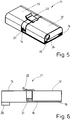
- the connector 11 can be seen in the assembled state.
- the length of the plugged-together connector 11 can be 50 mm to 200 mm, in particular 75 mm to 150 mm, preferably 100 mm.
- the height of the plug connection 11 is 5 mm to 30 mm, in particular 20 mm.
- the length of the plug can be 20 mm to 60 mm, in particular 30 mm to 50 mm, preferably 48 mm, while the width is 20 mm to 50 mm, in particular 30 mm to 40 mm, preferably 38 mm.
- the height of the plug is 5 mm to 30 mm, in particular 10 mm to 20 mm, preferably 18 mm.
- the length of the socket 13 with the guide element 16 corresponds to the length of the plug connection 11.
- the length of the socket 13 can, however, also differ from this value.
- the width and the height of the socket 13 also correspond to the width and the height of the plug connection 11. Here, too, it is conceivable that the dimensions of the socket 13 differ from those of the plug connection
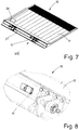
- a tail lift 10 is shown, which is assigned a plug connection 11 on a side 27 facing the loading area.
- the plug connection 11 can be attached to the loading platform 17 at any position.
- the ones in the Fig. 8 shown enlargements of the Fig. 7 shows that the plug connection 11 is arranged in a particularly protected position on the loading platform 17. For the sake of clarity, a cable for making contact with the plug connection 11 is not shown here.
Landscapes
- Engineering & Computer Science (AREA)
- Transportation (AREA)
- Mechanical Engineering (AREA)
- Details Of Connecting Devices For Male And Female Coupling (AREA)
- Forklifts And Lifting Vehicles (AREA)
Description
- Die Erfindung betrifft eine Hubladebühne gemäß dem Oberbegriff des Anspruchs 1.
- Eine solche Hubladebühne geht beispielsweise aus Dokument
DE 44 30 568 A1 hervor, welches den nächstliegenden Stand der Technik darstellt und den Oberbegriff des Anspruchs 1 offenbart. Hubladebühnen dienen dazu, bei Fahrzeugen aller Art das Be- und Entladen von Gütern zu erleichtern. Dazu verfügen diese Hubladebühnen über eine heb- und senkbar und im Allgemeinen auch schwenkbar an einem Fahrzeug angelenkte Ladeplattform. Die Ladeplattform ist zu diesem Zweck an der Rückseite des Fahrzeugs mit Hilfe eines Hubwerks angeordnet, vorzugsweise im Bereich der Rückseite eines Aufbaus des Fahrzeuges. Das Hubwerk weist üblicherweise zumindest einen Linearantrieb wie beispielsweise einen Hydraulikzylinder oder eine elektromotorisch antreibbare Gewindespindel, zum Heben bzw. Senken der Ladeplattform auf. Zum Verschwenken der Ladeplattform ist vorzugsweise wenigstens ein weiterer Linearantrieb vorgesehen. - Das Hubwerk ist im Regelfall an einem Tragrohr befestigt, das wiederum mit dem Fahrzeug verbunden ist, insbesondere im Bereich von dessen Fahrzeugrahmen bzw. dessen Längsträgern. Eine parallelogrammförmige Ausbildung des Hubwerks mit vorzugsweise wenigstens zwei, zumindest im Wesentlichen parallel verschwenkbaren Lenkerarmen sorgt dafür, dass die Ladeplattform in parallelen Ebenen höhenverstellbar ist. Zusätzlich bzw. unabhängig davon, kann die Ladeplattform verschwenkt werden.
- In der sogenannten Ruheposition liegt die Ladeplattform im Wesentlichen senkrecht ausgerichtet derart an der Rückseite des Aufbaus des Fahrzeuges an, dass eine an der Rückseite des Aufbaus angeordnete Öffnung durch die Ladeplattform verschließbar ist. In der sogenannten Betriebsposition ist die Ladeplattform im Wesentlichen horizontal ausgerichtet. Dabei ist die zumindest zwischen der Betriebsposition mit einem Niveau auf Höhe des Aufbaus bzw. der Ladefläche des Fahrzeugs zum Ein- und Ausladen von Gütern und der auch als Ladeposition bezeichneten Betriebsposition mit einer auf dem Boden aufliegenden Stellung der Ladeplattform zum Be- und Entladen von Gütern bewegbar. In der Ladeposition bzw. Stellung auf dem Boden ist die befahrbare Oberfläche bzw. Nutzfläche der Ladeplattform im Allgemeinen leicht geneigt gegenüber der Horizontalen ausgerichtet, da die Ladeplattform insgesamt einen keilförmigen Querschnitt aufweist. Dabei ist ein vom Fahrzeug abgewandter Querrand der Ladeplattform spitz zulaufend ausgebildet, während eine dem Fahrzeug zugewandte Querkante der Ladeplattform zur Anlenkung des Hubwerks entsprechend breiter bzw. höher ausgebildet ist.
- Zum Betätigen der Ladeplattform, insbesondere zum Verstellen der Ladeplattform aus einer Ruheposition in eine Ladeposition, ist es für die Steuerung essentiell, den Neigungswinkel der Ladeplattform bezüglich einer Referenzebene zu kennen. Es ist bekannt, dass den Ladeplattformen Neigungssensoren zugeordnet sind, welche eine relative Lage der Ladeplattform erstellen können. Dazu wird zusätzlich zu den übrigen Einrichtungen zum Steuern bzw. Überwachen der Ladeplattform ein Sensor zur Bestimmung des Neigungswinkels an der Ladeplattform befestigt. Für eine verlässliche Messung des Neigungswinkels kommt es darauf an, den Sensor an einer entsprechenden Position anzubringen. Wenn der Sensor in einer anderen Position an der Ladeplattform befestigt wird, kann es zu fehlerhaften Messungen des Neigungswinkels kommen und infolge dessen zur Beschädigung der Güter oder gar zur Verletzung der Bedienperson.
- Der Erfindung liegt daher die Aufgabe zugrunde, eine Hubladebühne zu schaffen, mit welcher der Betrieb auf eine einfache und sichere Art erfolgen kann.
- Eine Hubladebühne zur Lösung dieser genannten Aufgabe weist die Merkmale des Anspruchs 1 auf. Demnach ist es vorgesehen, dass die mindestens eine elektronische Komponente einer Steckverbindung mit einem Stecker und einer an der Hubladebühne befestigbaren Steckdose zugeordnet ist. Diese mindestens eine elektronische Komponente kann einer Steuerung zugeordnet sein, welche der Steuerung und/oder Überwachung des wenigstens einen Antriebs zum Heben, Senken und/oder Verschwenken der Ladeplattform dient. Die Hubladebühne gemäß Anspruch 6 ist insbesondere in Kombination zu betrachten mit einem der Ansprüche 1 bis 5. Dadurch, dass die mindestens eine elektronische Komponente der Steckverbindung zugeordnet ist, lässt sich die Komponente auf eine einfache Art und Weise an der Hubladebühne befestigen und ansteuern.
- Bevorzugt kann es weiter vorgesehen sein, dass die mindestens eine elektronische Komponente in dem Stecker und in der Steckdose integriert ist. Erfindungsgemäß ist die elektronische Komponente in dem Stecker integriert. Somit wird der Stecker lediglich in die Steckdose geführt, damit der Stecker die nötige mechanische Befestigung an der Hubladebühne erfährt. Sämtliche elektronischen Komponenten zur Steuerung des Betriebs der Hubladebühne befinden sich im Stecker. Somit lässt sich die Hubladebühne durch ein bloßes Zusammenstecken des Steckers mit der Steckdose in Betrieb nehmen. Ein weiteres Ausführungsbeispiel kann es vorsehen, dass sowohl der Stecker als auch die Steckdose elektronische Komponenten aufweisen, die unabhängig voneinander oder zusammengesteckt in Kombination miteinander zusammenwirken. Auch hier lässt sich durch das einfache mechanische Zusammenfügen des Steckers mit der Steckdose die Hubladebühne in Betrieb nehmen.
- Insbesondere kann es weiter vorgesehen sein, dass die mindestens eine elektronische Komponente mit dem Stecker und/oder der Steckdose lösbar, insbesondere austauschbar, verbunden ist. Somit ist es denkbar, dass dem Stecker verschiedenen Einsatzgebieten bzw. verschiedenen Anforderungen entsprechend elektronische Komponenten austauschbar zugeordnet werden. Dieses Zuordnen kann beispielsweise durch ein Hineinschieben der Komponente in den Stecker, durch eine Klickverbindung, eine Rastverbindung oder dergleichen erfolgen. Gleichermaßen kann die elektronische Komponente in einer Steckdose austauschbar mit selbiger verbunden sein.
- Ein weiteres besonderes vorteilhaftes Ausführungsbeispiel der vorliegenden Erfindung kann es vorsehen, dass die elektronische Komponente einen Neigungswinkelmesser, einen Beschleunigungssensor, ein Warnsignal, eine optische Einrichtung, eine akustische Einrichtung, einen Datenspeicher, eine Sendeeinrichtung, eine Empfangseinrichtung oder eine Schnittstelle für weitere elektronische Einrichtungen i umfasst Durch die elektronische Miniaturisierung der Komponenten lassen sich auch mehrere der genannten Gegenstände in den Stecker bzw. in die Steckdose integrieren. Insbesondere der in den Stecker und/oder in die Steckdose integrierte Neigungswinkelmesser ist für den Betrieb der Hubladebühne essentiell, da hierdurch die relative Lage der Ladeplattform im Raum bestimmbar ist. Ausgehend von diesem Signal wird die weitere Bewegung der Hubladebühne gesteuert.
- So kann es weiter vorgesehen sein, dass durch den Neigungswinkelmesser der relative Winkel der Ladeplattform zu einer, zwei oder drei Ebenen in einem kartesischen Koordinatensystem bestimmbar ist. Abhängig von der relativen Lage der Ladeplattform im Raum lässt sich diese durch Antriebe steuern. Dabei kann die Ladeplattform sowohl um eine, zwei oder drei Achsen den vorbestimmten Winkeln entsprechend verfahren werden.
- Außerdem kann es vorgesehen sein, dass die Steckverbindung, insbesondere der Stecker und/oder die Steckdose, mit einer Steuereinheit, vorzugsweise mit Fußbetätigungsmitteln, für die Ladeplattform verbunden ist und die Steuereinheit über die Steckverbindung, insbesondere den Stecker und/oder die Steckdose ansteuerbar ist. Die in die Ladeplattform integrierte Fußsteuerung ist mit einer elektronischen Komponente in der Steckverbindung, insbesondere in dem Stecker, verbunden. Die durch die Fußbetätigung an die elektronische Komponente übermittelten Daten werden von selbiger an die Antriebe weitergeleitet, sodass die Ladeplattform sich entsprechend der Fußbedienung bewegt. Somit lässt sich über die Steckverbindung sowohl die Lage der Ladeplattform bestimmen, als auch Steuersignale für die Ausrichtung der Ladeplattform im Raum aufnehmen, um diese an die entsprechenden Antriebe weiterzuleiten.
- Darüber hinaus kann es durch ein weiteres Ausführungsbeispiel vorgesehen sein, dass eine optische und/oder eine akustische Signaleinrichtung an der Ladeplattform über die Steckverbindung, insbesondere den Stecker und/oder die Steckdose, ansteuerbar sind. Eine Ladeplattform weist üblicherweise an den Seitenkanten Signalmittel wie beispielsweise Blinklichter auf. Diese Signalmittel lassen sich ebenfalls über die Steckverbindung bzw. über die in der Steckverbindung integrierte elektronische Komponente ansteuern bzw. mit elektrischer Energie versorgen.
- Bevorzugt kann es außerdem vorgesehen sein, dass die Steckverbindung, insbesondere der Stecker und/oder die Steckdose, zur Energieversorgung und/oder Datenübertragung über eine Leitung mit einer Steuereinrichtung zum Steuern und/oder eine Einrichtung zum Überwachen der Antriebe verbunden sind. Somit lässt sich über die Steckverbindung bzw. über die in dem Stecker integrierte elektronische Komponente durch einfaches Zusammenstecken die gesamte Hubladebühne bzw. die Ladeplattform auf eine einfache Art und Weise in Betrieb nehmen. Durch das einfache Verbinden des Steckers mit der Steckdose können selbige auf eine verlässliche Art und Weise zusammengeführt werden. Ein bevorzugtes Ausführungsbeispiel der Erfindung wird im Folgenden anhand der Zeichnung näher beschrieben. In dieser zeigt:
- Fig. 1
- eine perspektivische Darstellung eines Steckers einer Steckverbindung,
- Fig. 2
- eine perspektivische Darstellung einer Steckdose der Steckverbindung,
- Fig. 3
- eine perspektivische Ansicht der Steckverbindung beim Zusammenfügen,
- Fig. 4
- eine Seitenansicht der Steckverbindung gemäß der
Fig. 3 , - Fig. 5
- eine perspektivische Ansicht der zusammengesetzten Steckverbindung,
- Fig. 6
- eine Seitenansicht der in
Fig. 5 dargestellten Steckverbindung, - Fig. 7
- eine Hubladebühne mit der Steckverbindung, und
- Fig. 8
- eine Darstellung einer Ausschnittsvergrößerung der
Fig. 7 . - Zur elektrischen Kontaktierung einer Hubladebühne 10 zum Anbauen an ein Fahrzeug dient erfindungsgemäß eine Steckverbindung 11. Diese Steckverbindung 11 kann auch selbst als ein elektrisches Anbauteil, wie beispielsweise ein Sensor, ausgebildet sein. Die Steckverbindung besteht im Wesentlichen aus einem Stecker 12 (
Fig. 1 ) und einer mit dem Stecker 12 korrespondieren Steckdose 13 (Fig. 2 ). - Zum Verbinden des Steckers 12 mit der Steckdose 13 weist der Stecker 12 zwei Gleitorgane 14 auf, welche sich auf Schienen 15 der Steckdose 13 fügen und verschieben lassen (
Fig. 1, 2 ). Somit lässt sich der Stecker 12 auf einem die Schienen 15 aufweisenden Führungselement 16, welches einstückig mit der Steckdose 13 verbunden ist, führen und mit der Steckdose 13 in Kontakt bringen. - Sowohl der Stecker 12 als auch die Steckdose 13 sind bei dem hier dargestellten Ausführungsbeispiel quaderförmig ausgebildet und weisen in ihrem Inneren ein Hohlraum auf. Es ist jedoch auch denkbar, dass der Stecker 12 bzw. die Steckdose 13 eine andere Form aufweisen. Die Hohlräume des Steckers und der Steckdose 13 dienen der Aufnahme einer elektronischen Komponente 20. Diese mindestens eine elektronische Komponente 20 kann zur Steuerung wenigstens eines Antriebes der Hubladebühne 10 dienen. Bei dieser elektronischen Komponente 20 kann es sich jedoch auch um Sensoren jeglicher Art und andere elektronische Einrichtungen handeln.
- Die Steckdose 13 kann derart ausgebildet sein, dass sie lediglich als Halterung für den die elektronische Komponente 20 aufweisenden Stecker 12 dient. Es ist erfindungsgemäß aber auch vorgesehen, dass die Steckdose 13 selbst elektronische Komponenten 20 aufweist, die durch den Stecker 12 lediglich angesteuert und/oder mit Energie versorgt werden. Darüber hinaus kann es vorgesehen sein, dass der Stecker 12 und die Steckdose 13 jeweils eine elektronische Komponente 20 aufweisen, die im zusammengesteckten Zustand einer bestimmten Funktion aufweisen.
- Die Steckdose 13 weist für die Befestigung der Steckdose 13 bzw. der Steckverbindung 11 an der Hubladebühne 10 bzw. einer Ladeplattform 17 Bohrungen 18 auf. Diese Bohrungen 18 sind dem Führungselement 16 zugeordnet.
- In der
Fig. 3 ist dargestellt, wie der Stecker 12 mit den Gleitorganen 14 in Richtung 19 auf das Führungselement 16 geschoben wird, um dann in Kontakt mit der Steckdose 13 zu treten. Bei dem in derFig. 3 dargestellten Ausführungsbeispiel weist der Stecker 12 eine elektronische Komponente 20 auf, welche in einer Aufnahme 21 positioniert ist, die in der Steckdose 13 angeordnet ist. - Der Stecker 12 weist für eine lösbare Verbindung mit der Steckdose 13 ein hebelartiges Rastmittel 22 auf, welches beim Zusammenfügen des Steckers 12 mit der Steckdose 13 über eine Rastnase 23 führbar und dort arretierbar ist. Durch diese rastende Verbindung des Steckers 12 mit der Steckdose 13 kann sichergestellt werden, dass die Steckverbindung 11 auch bei schweren Erschütterungen nicht gelöst wird.
- Für die Ansteuerung der elektronischen Komponenten 20 im Stecker 12 bzw. für die Energieversorgung der elektronischen Komponente 20 weist der Stecker 12 einen Kabelausgang 24 auf, durch den ein nicht dargestelltes Kabel mit der elektronischen Komponente 20 verbindbar ist (
Fig. 3 ). - Die Steckdose 13 kann des Weiteren ebenfalls einen Kabelausgang 25 aufweisen, über den sich die Steckverbindung 11 bzw. der Stecker 12 und/oder die Steckdose 13 mit der Ladeplattform 17 durch ein nicht dargestelltes Kabel verbinden lassen (
Fig. 4 ). Dieses Kabel kann dann beispielsweise zur Kontaktierung eines Fußpedals 26, einer optischen Signaleinrichtungen oder dergleichen dienen. - In den
Fig. 5 und 6 ist die Steckverbindung 11 in dem zusammengefügten Zustand zu sehen. Die Länge der zusammengesteckten Steckverbindung 11 kann 50 mm bis 200 mm, insbesondere 75 mm bis 150 mm, vorzugsweise 100 mm betragen. Die Höhe der Steckverbindung 11 beträgt 5 mm bis 30 mm, insbesondere 20 mm. Die Länge des Steckers kann 20 mm bis 60 mm, insbesondere 30 mm bis 50 mm, vorzugsweise 48 mm, betragen, während die Breite 20 mm bis 50 mm, insbesondere 30 mm bis 40 mm, vorzugsweise 38 mm beträgt. Die Höhe des Steckers beträgt 5 mm bis 30 mm, insbesondere 10 mm bis 20 mm, vorzugsweise 18 mm. Die Länge der Steckdose 13 mit dem Führungselement 16 entspricht der Länge der Steckverbindung 11. Die Länge der Steckdose 13 kann jedoch auch von diesem Wert abweichen. Gleichermaßen entsprechen auch die Breite sowie die Höhe der Steckdose 13 der Breite und der Höhe der Steckverbindung 11. Auch hier ist es denkbar, dass die Dimensionierung der Steckdose 13 von der der Steckverbindung 11 abweicht. - In der
Fig. 7 ist eine Hubladebühne 10 dargestellt, welche an einer der Ladefläche zugewandten Seite 27 eine Steckverbindung 11 zugeordnet ist. Prinzipiell lässt sich die Steckverbindung 11 an jeder beliebigen Position an der Ladeplattform 17 befestigen. Die in derFig. 8 dargestellte Ausschnittsvergrößerungen derFig. 7 zeigt, dass die Steckverbindung 11 an einer besonders geschützten Position an der Ladeplattform 17 angeordnet ist. Aus Gründen der Übersichtlichkeit ist ein Kabel zur Kontaktierung der Steckverbindung 11 hier nicht dargestellt. - Für die Installation der Steckverbindung 11 ist lediglich der die elektronische Komponente 20 aufweisenden Stecker 12, welcher mit einem Kabel an die Steuereinrichtung des Fahrzeugs gekoppelt ist, in die an der Ladeplattform 17 befestigten Steckdose 13 einzurasten. Durch das Führungselement 16 ist die Position der Steckdose 13 und damit auch die Position der elektronischen Komponente 20 an der Hubladebühne 10 klar vordefiniert. Das heiß, dass beispielsweise Winkelsensoren derart vorkonfigurierbar bzw. vorinstallierbar sind, dass sie nach dem Einrasten in der Steckdose 13 sofort in Betrieb nehmbar sind, ohne dass eine eventuell notwendige Eichung oder Kalibrierung der Sensoren notwendig ist. Auf diese Weise lässt sich eine besonders einfache und sichere Inbetriebnahme jeglicher elektronischer Komponenten, insbesondere der Sensoren, gewährleisten.
-
- 10
- Hubladebühne
- 11
- Steckverbindung
- 12
- Stecker
- 13
- Steckdose
- 14
- Gleitorgan
- 15
- Schiene
- 16
- Führungselement
- 17
- Ladeplattform
- 18
- Bohrung
- 19
- Richtung
- 20
- elektronische Komponente
- 21
- Aufnahme
- 22
- Rastmittel
- 23
- Rastnase
- 24
- Kabelausgang
- 25
- Kabelausgang
- 26
- Fußpedal
- 27
- Seite
Claims (8)
- Hubladebühne (10) zum Anbau an ein Fahrzeug mit einer Ladeplattform (17), einem Hubwerk, das wenigstens einen Antrieb zum Heben, Senken und/oder Verschwenken der Ladeplattform (17) aufweist und mit mindestens einer einer Steuerung zugeordneten elektronischen Komponente (20) zur Steuerung des wenigstens einen Antriebs, dadurch gekennzeichnet, dass die mindestens eine elektronische Komponente (20) einer Steckverbindung (11) mit einem Stecker (12) und einer an der Hubladebühne (10) befestigbaren Steckdose (13) zugeordnet ist, wobei es sich bei der elektronischen Komponente (20) um einen Sensor handelt, der in den Stecker (12) integriert ist und wobei die Hubladebühne (10) durch Zusammenstecken des den Sensor aufweisenden Steckers (12) mit der an der Hubladebühne (10) befestigten Steckdose (13) in Betrieb nehmbar ist.
- Hubladebühne (10) nach Anspruch 1, dadurch gekennzeichnet, dass die mindestens eine elektronische Komponente (20) in dem Stecker (12) und in der Steckdose (13) integriert ist.
- Hubladebühne (10) nach Anspruch 1 oder 2, dadurch gekennzeichnet, dass die mindestens eine elektronische Komponente (20) mit dem Stecker (12) und/oder der Steckdose (13) lösbar, insbesondere austauschbar, verbunden ist.
- Hubladebühne (10) nach einem der vorherigen Ansprüche, dadurch gekennzeichnet, dass die elektronische Komponente (20) einen Neigungswinkelmesser, einen Beschleunigungssensor, ein Warnsignal, eine optische Einrichtung, eine akustische Einrichtung, einen Datenspeicher, eine Sendeeinrichtung, eine Empfangseinrichtung oder eine Schnittstelle für weitere elektronische Einrichtungen umfasst.
- Hubladebühne (10) nach Anspruch 4, dadurch gekennzeichnet, dass durch den Neigungswinkelmesser der relative Winkel der Ladeplattform (17) zu einer, zwei oder drei Ebenen in einem kartesischen Koordinatensystem bestimmbar ist.
- Hubladebühne (10) nach einem der vorherigen Ansprüche, dadurch gekennzeichnet, dass die Steckverbindung (11), insbesondere der Stecker (12) und/oder die Steckdose (13), mit einer Steuereinheit, vorzugsweise mit Fußbetätigungsmitteln (26), für die Ladeplattform (17) verbunden ist und die Steuereinheit über die Steckverbindung (11), insbesondere den Stecker (12) und/oder die Steckdose (13), ansteuerbar ist.
- Hubladebühne (10) nach einem der vorherigen Ansprüche, dadurch gekennzeichnet, dass eine optische und/oder akustische Signaleinrichtung an der Ladeplattform (17) über die Steckverbindung (11), insbesondere den Stecker (12) und/oder die Steckdose (13), ansteuerbar ist.
- Hubladebühne (10) nach einem der vorherigen Ansprüche, dadurch gekennzeichnet, dass die Steckverbindung (11), insbesondere der Stecker (12) und/oder die Steckdose (13), zur Energieversorgung und/oder Datenübertragung über eine Leitung mit einer Steuereinrichtung zum Steuern und/oder einer Einrichtung zum Überwachen der Antriebe verbunden ist.
Applications Claiming Priority (2)
| Application Number | Priority Date | Filing Date | Title |
|---|---|---|---|
| DE102016009156.8A DE102016009156A1 (de) | 2016-07-28 | 2016-07-28 | Hubladebühne |
| EP17001177.9A EP3275730B1 (de) | 2016-07-28 | 2017-07-11 | Hubladebühne |
Related Parent Applications (2)
| Application Number | Title | Priority Date | Filing Date |
|---|---|---|---|
| EP17001177.9A Division EP3275730B1 (de) | 2016-07-28 | 2017-07-11 | Hubladebühne |
| EP17001177.9A Division-Into EP3275730B1 (de) | 2016-07-28 | 2017-07-11 | Hubladebühne |
Publications (2)
| Publication Number | Publication Date |
|---|---|
| EP3461686A1 EP3461686A1 (de) | 2019-04-03 |
| EP3461686B1 true EP3461686B1 (de) | 2020-12-16 |
Family
ID=59337402
Family Applications (2)
| Application Number | Title | Priority Date | Filing Date |
|---|---|---|---|
| EP18000892.2A Active EP3461686B1 (de) | 2016-07-28 | 2017-07-11 | Hubladebühne |
| EP17001177.9A Active EP3275730B1 (de) | 2016-07-28 | 2017-07-11 | Hubladebühne |
Family Applications After (1)
| Application Number | Title | Priority Date | Filing Date |
|---|---|---|---|
| EP17001177.9A Active EP3275730B1 (de) | 2016-07-28 | 2017-07-11 | Hubladebühne |
Country Status (2)
| Country | Link |
|---|---|
| EP (2) | EP3461686B1 (de) |
| DE (1) | DE102016009156A1 (de) |
Family Cites Families (4)
| Publication number | Priority date | Publication date | Assignee | Title |
|---|---|---|---|---|
| DE8020141U1 (de) * | 1980-07-26 | 1980-11-06 | Wilhelm Stoll Maschinenfabrik Gmbh, 3325 Lengede | Ladebordwand |
| DE4430568B4 (de) * | 1994-08-30 | 2010-01-07 | Dautel Gmbh | Hubladebühne für ein Lastfahrzeug |
| US9090200B2 (en) * | 2005-06-16 | 2015-07-28 | Peter Maier Leichtbau Gmbh | Tailgate |
| DE102006010261A1 (de) * | 2006-03-02 | 2007-09-06 | Gisela Weber | Montagesatz für eine Ladebordwand |
-
2016
- 2016-07-28 DE DE102016009156.8A patent/DE102016009156A1/de not_active Withdrawn
-
2017
- 2017-07-11 EP EP18000892.2A patent/EP3461686B1/de active Active
- 2017-07-11 EP EP17001177.9A patent/EP3275730B1/de active Active
Non-Patent Citations (1)
| Title |
|---|
| None * |
Also Published As
| Publication number | Publication date |
|---|---|
| EP3275730A2 (de) | 2018-01-31 |
| DE102016009156A1 (de) | 2018-02-01 |
| EP3275730A3 (de) | 2018-05-16 |
| EP3461686A1 (de) | 2019-04-03 |
| EP3275730B1 (de) | 2020-01-08 |
Similar Documents
| Publication | Publication Date | Title |
|---|---|---|
| EP0583655B1 (de) | Flugzeug-Arbeitsdock | |
| EP3377274B1 (de) | Ankoppeleinrichtung und ankoppelverfahren | |
| DE3318077C2 (de) | Schleppfahrzeug für Flugzeuge | |
| EP1614398B1 (de) | Munddusche mit zwei miteinander verbindbaren Gehäusen | |
| EP0344401A1 (de) | Sicherheitsvorrichtung für eine automatisch bewegte Fensterscheibe eines Kraftfahrzeugs | |
| EP1925513B1 (de) | Flurförderzeug mit einer Vorrichtung zum seitlichen Ausziehen einer Energieversorgungseinheit | |
| DE102007051472A1 (de) | Montagevorrichtung | |
| EP0371227A2 (de) | Deichsel für von Hand geführte Hubwagen und -lader | |
| DE2240274C3 (de) | Ferngesteuerte Lenkvorrichtung für Fahrzeuge | |
| EP3284635B1 (de) | Schutzvorrichtung für einen fahrzeuginnenraum | |
| EP3259170B1 (de) | Verfahren und einrichtung zur zentrierung einer ungekuppelten mittelpufferkupplung | |
| EP3661866A1 (de) | Vorrichtung zur aufnahme und zum transport von lasten | |
| DE10023641B4 (de) | Anhängerkupplung | |
| EP3205607B1 (de) | Verfahren und vorrichtung zur förderung eines regallager-transportfahrzeugs | |
| EP3275730B1 (de) | Hubladebühne | |
| DE2307955A1 (de) | Rettungs- und/oder arbeitskorb | |
| EP0237869A2 (de) | Filterpresse | |
| DE102020203559A1 (de) | Prüffahrzeug | |
| DE102008031462A1 (de) | Motorische Vorrichtung zum Ausfahren von Schubladen | |
| EP2101145A1 (de) | Mess-Gerät und Verfahren zur Erfassung des Verschleiss-Zustandes von Bohrungen von Schnecken-Extrudern | |
| CH684256A5 (de) | Vorrichtung zum Halten einer Leiter auf einem Dach eines Fahrzeuges. | |
| CH703049B1 (de) | Vorrichtung zum Anheben und Absenken von Lasten. | |
| EP0438998B1 (de) | Transportwagen, insbesondere Niederflurwagen, sowie ein Verfahren zum Be- und Entladen desselben | |
| DE102015121151A1 (de) | Lastwiegevorrichtung für Flurförderzeug | |
| DE10054791A1 (de) | Lasthandhabungsvorrichtung für ein Flurförderzeug |
Legal Events
| Date | Code | Title | Description |
|---|---|---|---|
| PUAI | Public reference made under article 153(3) epc to a published international application that has entered the european phase |
Free format text: ORIGINAL CODE: 0009012 |
|
| STAA | Information on the status of an ep patent application or granted ep patent |
Free format text: STATUS: THE APPLICATION HAS BEEN PUBLISHED |
|
| AC | Divisional application: reference to earlier application |
Ref document number: 3275730 Country of ref document: EP Kind code of ref document: P |
|
| AK | Designated contracting states |
Kind code of ref document: A1 Designated state(s): AL AT BE BG CH CY CZ DE DK EE ES FI FR GB GR HR HU IE IS IT LI LT LU LV MC MK MT NL NO PL PT RO RS SE SI SK SM TR |
|
| AX | Request for extension of the european patent |
Extension state: BA ME |
|
| STAA | Information on the status of an ep patent application or granted ep patent |
Free format text: STATUS: REQUEST FOR EXAMINATION WAS MADE |
|
| 17P | Request for examination filed |
Effective date: 20190924 |
|
| RBV | Designated contracting states (corrected) |
Designated state(s): AL AT BE BG CH CY CZ DE DK EE ES FI FR GB GR HR HU IE IS IT LI LT LU LV MC MK MT NL NO PL PT RO RS SE SI SK SM TR |
|
| GRAP | Despatch of communication of intention to grant a patent |
Free format text: ORIGINAL CODE: EPIDOSNIGR1 |
|
| STAA | Information on the status of an ep patent application or granted ep patent |
Free format text: STATUS: GRANT OF PATENT IS INTENDED |
|
| INTG | Intention to grant announced |
Effective date: 20200629 |
|
| GRAS | Grant fee paid |
Free format text: ORIGINAL CODE: EPIDOSNIGR3 |
|
| GRAA | (expected) grant |
Free format text: ORIGINAL CODE: 0009210 |
|
| STAA | Information on the status of an ep patent application or granted ep patent |
Free format text: STATUS: THE PATENT HAS BEEN GRANTED |
|
| AC | Divisional application: reference to earlier application |
Ref document number: 3275730 Country of ref document: EP Kind code of ref document: P |
|
| AK | Designated contracting states |
Kind code of ref document: B1 Designated state(s): AL AT BE BG CH CY CZ DE DK EE ES FI FR GB GR HR HU IE IS IT LI LT LU LV MC MK MT NL NO PL PT RO RS SE SI SK SM TR |
|
| REG | Reference to a national code |
Ref country code: GB Ref legal event code: FG4D Free format text: NOT ENGLISH |
|
| REG | Reference to a national code |
Ref country code: IE Ref legal event code: FG4D Free format text: LANGUAGE OF EP DOCUMENT: GERMAN |
|
| REG | Reference to a national code |
Ref country code: DE Ref legal event code: R096 Ref document number: 502017008727 Country of ref document: DE |
|
| REG | Reference to a national code |
Ref country code: AT Ref legal event code: REF Ref document number: 1345300 Country of ref document: AT Kind code of ref document: T Effective date: 20210115 |
|
| PG25 | Lapsed in a contracting state [announced via postgrant information from national office to epo] |
Ref country code: RS Free format text: LAPSE BECAUSE OF FAILURE TO SUBMIT A TRANSLATION OF THE DESCRIPTION OR TO PAY THE FEE WITHIN THE PRESCRIBED TIME-LIMIT Effective date: 20201216 Ref country code: FI Free format text: LAPSE BECAUSE OF FAILURE TO SUBMIT A TRANSLATION OF THE DESCRIPTION OR TO PAY THE FEE WITHIN THE PRESCRIBED TIME-LIMIT Effective date: 20201216 Ref country code: NO Free format text: LAPSE BECAUSE OF FAILURE TO SUBMIT A TRANSLATION OF THE DESCRIPTION OR TO PAY THE FEE WITHIN THE PRESCRIBED TIME-LIMIT Effective date: 20210316 Ref country code: GR Free format text: LAPSE BECAUSE OF FAILURE TO SUBMIT A TRANSLATION OF THE DESCRIPTION OR TO PAY THE FEE WITHIN THE PRESCRIBED TIME-LIMIT Effective date: 20210317 |
|
| REG | Reference to a national code |
Ref country code: NL Ref legal event code: MP Effective date: 20201216 |
|
| PG25 | Lapsed in a contracting state [announced via postgrant information from national office to epo] |
Ref country code: BG Free format text: LAPSE BECAUSE OF FAILURE TO SUBMIT A TRANSLATION OF THE DESCRIPTION OR TO PAY THE FEE WITHIN THE PRESCRIBED TIME-LIMIT Effective date: 20210316 Ref country code: LV Free format text: LAPSE BECAUSE OF FAILURE TO SUBMIT A TRANSLATION OF THE DESCRIPTION OR TO PAY THE FEE WITHIN THE PRESCRIBED TIME-LIMIT Effective date: 20201216 Ref country code: SE Free format text: LAPSE BECAUSE OF FAILURE TO SUBMIT A TRANSLATION OF THE DESCRIPTION OR TO PAY THE FEE WITHIN THE PRESCRIBED TIME-LIMIT Effective date: 20201216 |
|
| PG25 | Lapsed in a contracting state [announced via postgrant information from national office to epo] |
Ref country code: HR Free format text: LAPSE BECAUSE OF FAILURE TO SUBMIT A TRANSLATION OF THE DESCRIPTION OR TO PAY THE FEE WITHIN THE PRESCRIBED TIME-LIMIT Effective date: 20201216 Ref country code: NL Free format text: LAPSE BECAUSE OF FAILURE TO SUBMIT A TRANSLATION OF THE DESCRIPTION OR TO PAY THE FEE WITHIN THE PRESCRIBED TIME-LIMIT Effective date: 20201216 |
|
| REG | Reference to a national code |
Ref country code: LT Ref legal event code: MG9D |
|
| PG25 | Lapsed in a contracting state [announced via postgrant information from national office to epo] |
Ref country code: PT Free format text: LAPSE BECAUSE OF FAILURE TO SUBMIT A TRANSLATION OF THE DESCRIPTION OR TO PAY THE FEE WITHIN THE PRESCRIBED TIME-LIMIT Effective date: 20210416 Ref country code: RO Free format text: LAPSE BECAUSE OF FAILURE TO SUBMIT A TRANSLATION OF THE DESCRIPTION OR TO PAY THE FEE WITHIN THE PRESCRIBED TIME-LIMIT Effective date: 20201216 Ref country code: SK Free format text: LAPSE BECAUSE OF FAILURE TO SUBMIT A TRANSLATION OF THE DESCRIPTION OR TO PAY THE FEE WITHIN THE PRESCRIBED TIME-LIMIT Effective date: 20201216 Ref country code: SM Free format text: LAPSE BECAUSE OF FAILURE TO SUBMIT A TRANSLATION OF THE DESCRIPTION OR TO PAY THE FEE WITHIN THE PRESCRIBED TIME-LIMIT Effective date: 20201216 Ref country code: CZ Free format text: LAPSE BECAUSE OF FAILURE TO SUBMIT A TRANSLATION OF THE DESCRIPTION OR TO PAY THE FEE WITHIN THE PRESCRIBED TIME-LIMIT Effective date: 20201216 Ref country code: EE Free format text: LAPSE BECAUSE OF FAILURE TO SUBMIT A TRANSLATION OF THE DESCRIPTION OR TO PAY THE FEE WITHIN THE PRESCRIBED TIME-LIMIT Effective date: 20201216 Ref country code: LT Free format text: LAPSE BECAUSE OF FAILURE TO SUBMIT A TRANSLATION OF THE DESCRIPTION OR TO PAY THE FEE WITHIN THE PRESCRIBED TIME-LIMIT Effective date: 20201216 |
|
| PG25 | Lapsed in a contracting state [announced via postgrant information from national office to epo] |
Ref country code: PL Free format text: LAPSE BECAUSE OF FAILURE TO SUBMIT A TRANSLATION OF THE DESCRIPTION OR TO PAY THE FEE WITHIN THE PRESCRIBED TIME-LIMIT Effective date: 20201216 |
|
| REG | Reference to a national code |
Ref country code: DE Ref legal event code: R097 Ref document number: 502017008727 Country of ref document: DE |
|
| PG25 | Lapsed in a contracting state [announced via postgrant information from national office to epo] |
Ref country code: IS Free format text: LAPSE BECAUSE OF FAILURE TO SUBMIT A TRANSLATION OF THE DESCRIPTION OR TO PAY THE FEE WITHIN THE PRESCRIBED TIME-LIMIT Effective date: 20210416 |
|
| PLBE | No opposition filed within time limit |
Free format text: ORIGINAL CODE: 0009261 |
|
| STAA | Information on the status of an ep patent application or granted ep patent |
Free format text: STATUS: NO OPPOSITION FILED WITHIN TIME LIMIT |
|
| PG25 | Lapsed in a contracting state [announced via postgrant information from national office to epo] |
Ref country code: IT Free format text: LAPSE BECAUSE OF FAILURE TO SUBMIT A TRANSLATION OF THE DESCRIPTION OR TO PAY THE FEE WITHIN THE PRESCRIBED TIME-LIMIT Effective date: 20201216 Ref country code: AL Free format text: LAPSE BECAUSE OF FAILURE TO SUBMIT A TRANSLATION OF THE DESCRIPTION OR TO PAY THE FEE WITHIN THE PRESCRIBED TIME-LIMIT Effective date: 20201216 |
|
| 26N | No opposition filed |
Effective date: 20210917 |
|
| PG25 | Lapsed in a contracting state [announced via postgrant information from national office to epo] |
Ref country code: DK Free format text: LAPSE BECAUSE OF FAILURE TO SUBMIT A TRANSLATION OF THE DESCRIPTION OR TO PAY THE FEE WITHIN THE PRESCRIBED TIME-LIMIT Effective date: 20201216 |
|
| PG25 | Lapsed in a contracting state [announced via postgrant information from national office to epo] |
Ref country code: ES Free format text: LAPSE BECAUSE OF FAILURE TO SUBMIT A TRANSLATION OF THE DESCRIPTION OR TO PAY THE FEE WITHIN THE PRESCRIBED TIME-LIMIT Effective date: 20201216 |
|
| PG25 | Lapsed in a contracting state [announced via postgrant information from national office to epo] |
Ref country code: SI Free format text: LAPSE BECAUSE OF FAILURE TO SUBMIT A TRANSLATION OF THE DESCRIPTION OR TO PAY THE FEE WITHIN THE PRESCRIBED TIME-LIMIT Effective date: 20201216 |
|
| REG | Reference to a national code |
Ref country code: CH Ref legal event code: PL |
|
| PG25 | Lapsed in a contracting state [announced via postgrant information from national office to epo] |
Ref country code: MC Free format text: LAPSE BECAUSE OF FAILURE TO SUBMIT A TRANSLATION OF THE DESCRIPTION OR TO PAY THE FEE WITHIN THE PRESCRIBED TIME-LIMIT Effective date: 20201216 |
|
| REG | Reference to a national code |
Ref country code: BE Ref legal event code: MM Effective date: 20210731 |
|
| PG25 | Lapsed in a contracting state [announced via postgrant information from national office to epo] |
Ref country code: LI Free format text: LAPSE BECAUSE OF NON-PAYMENT OF DUE FEES Effective date: 20210731 Ref country code: CH Free format text: LAPSE BECAUSE OF NON-PAYMENT OF DUE FEES Effective date: 20210731 |
|
| PG25 | Lapsed in a contracting state [announced via postgrant information from national office to epo] |
Ref country code: IS Free format text: LAPSE BECAUSE OF FAILURE TO SUBMIT A TRANSLATION OF THE DESCRIPTION OR TO PAY THE FEE WITHIN THE PRESCRIBED TIME-LIMIT Effective date: 20210416 Ref country code: LU Free format text: LAPSE BECAUSE OF NON-PAYMENT OF DUE FEES Effective date: 20210711 |
|
| PG25 | Lapsed in a contracting state [announced via postgrant information from national office to epo] |
Ref country code: IE Free format text: LAPSE BECAUSE OF NON-PAYMENT OF DUE FEES Effective date: 20210711 Ref country code: BE Free format text: LAPSE BECAUSE OF NON-PAYMENT OF DUE FEES Effective date: 20210731 |
|
| REG | Reference to a national code |
Ref country code: DE Ref legal event code: R081 Ref document number: 502017008727 Country of ref document: DE Owner name: PALFINGER TAIL LIFTS GMBH, DE Free format text: FORMER OWNER: PALFINGER TAIL LIFTS GMBH, 27777 GANDERKESEE, DE |
|
| PG25 | Lapsed in a contracting state [announced via postgrant information from national office to epo] |
Ref country code: CY Free format text: LAPSE BECAUSE OF FAILURE TO SUBMIT A TRANSLATION OF THE DESCRIPTION OR TO PAY THE FEE WITHIN THE PRESCRIBED TIME-LIMIT Effective date: 20201216 |
|
| PG25 | Lapsed in a contracting state [announced via postgrant information from national office to epo] |
Ref country code: HU Free format text: LAPSE BECAUSE OF FAILURE TO SUBMIT A TRANSLATION OF THE DESCRIPTION OR TO PAY THE FEE WITHIN THE PRESCRIBED TIME-LIMIT; INVALID AB INITIO Effective date: 20170711 |
|
| P01 | Opt-out of the competence of the unified patent court (upc) registered |
Effective date: 20230701 |
|
| REG | Reference to a national code |
Ref country code: GB Ref legal event code: 732E Free format text: REGISTERED BETWEEN 20230720 AND 20230726 |
|
| REG | Reference to a national code |
Ref country code: AT Ref legal event code: MM01 Ref document number: 1345300 Country of ref document: AT Kind code of ref document: T Effective date: 20220711 |
|
| PG25 | Lapsed in a contracting state [announced via postgrant information from national office to epo] |
Ref country code: AT Free format text: LAPSE BECAUSE OF NON-PAYMENT OF DUE FEES Effective date: 20220711 |
|
| PG25 | Lapsed in a contracting state [announced via postgrant information from national office to epo] |
Ref country code: MK Free format text: LAPSE BECAUSE OF FAILURE TO SUBMIT A TRANSLATION OF THE DESCRIPTION OR TO PAY THE FEE WITHIN THE PRESCRIBED TIME-LIMIT Effective date: 20201216 |
|
| PG25 | Lapsed in a contracting state [announced via postgrant information from national office to epo] |
Ref country code: TR Free format text: LAPSE BECAUSE OF FAILURE TO SUBMIT A TRANSLATION OF THE DESCRIPTION OR TO PAY THE FEE WITHIN THE PRESCRIBED TIME-LIMIT Effective date: 20201216 |
|
| PG25 | Lapsed in a contracting state [announced via postgrant information from national office to epo] |
Ref country code: MT Free format text: LAPSE BECAUSE OF FAILURE TO SUBMIT A TRANSLATION OF THE DESCRIPTION OR TO PAY THE FEE WITHIN THE PRESCRIBED TIME-LIMIT Effective date: 20201216 |
|
| PGFP | Annual fee paid to national office [announced via postgrant information from national office to epo] |
Ref country code: DE Payment date: 20250627 Year of fee payment: 9 |
|
| PGFP | Annual fee paid to national office [announced via postgrant information from national office to epo] |
Ref country code: GB Payment date: 20250724 Year of fee payment: 9 |
|
| PGFP | Annual fee paid to national office [announced via postgrant information from national office to epo] |
Ref country code: FR Payment date: 20250723 Year of fee payment: 9 |