EP3459908A1 - Verfahren zur herstellung einer permeationsmembran - Google Patents
Verfahren zur herstellung einer permeationsmembran Download PDFInfo
- Publication number
- EP3459908A1 EP3459908A1 EP18193984.4A EP18193984A EP3459908A1 EP 3459908 A1 EP3459908 A1 EP 3459908A1 EP 18193984 A EP18193984 A EP 18193984A EP 3459908 A1 EP3459908 A1 EP 3459908A1
- Authority
- EP
- European Patent Office
- Prior art keywords
- palladium
- carrier system
- hydrogen
- membrane
- permeation
- Prior art date
- Legal status (The legal status is an assumption and is not a legal conclusion. Google has not performed a legal analysis and makes no representation as to the accuracy of the status listed.)
- Granted
Links
Images
Classifications
-
- B—PERFORMING OPERATIONS; TRANSPORTING
- B01—PHYSICAL OR CHEMICAL PROCESSES OR APPARATUS IN GENERAL
- B01D—SEPARATION
- B01D67/00—Processes specially adapted for manufacturing semi-permeable membranes for separation processes or apparatus
- B01D67/0039—Inorganic membrane manufacture
- B01D67/0069—Inorganic membrane manufacture by deposition from the liquid phase, e.g. electrochemical deposition
-
- B—PERFORMING OPERATIONS; TRANSPORTING
- B01—PHYSICAL OR CHEMICAL PROCESSES OR APPARATUS IN GENERAL
- B01D—SEPARATION
- B01D19/00—Degasification of liquids
- B01D19/0031—Degasification of liquids by filtration
-
- B—PERFORMING OPERATIONS; TRANSPORTING
- B01—PHYSICAL OR CHEMICAL PROCESSES OR APPARATUS IN GENERAL
- B01D—SEPARATION
- B01D53/00—Separation of gases or vapours; Recovering vapours of volatile solvents from gases; Chemical or biological purification of waste gases, e.g. engine exhaust gases, smoke, fumes, flue gases, aerosols
- B01D53/22—Separation of gases or vapours; Recovering vapours of volatile solvents from gases; Chemical or biological purification of waste gases, e.g. engine exhaust gases, smoke, fumes, flue gases, aerosols by diffusion
- B01D53/228—Separation of gases or vapours; Recovering vapours of volatile solvents from gases; Chemical or biological purification of waste gases, e.g. engine exhaust gases, smoke, fumes, flue gases, aerosols by diffusion characterised by specific membranes
-
- B—PERFORMING OPERATIONS; TRANSPORTING
- B01—PHYSICAL OR CHEMICAL PROCESSES OR APPARATUS IN GENERAL
- B01D—SEPARATION
- B01D67/00—Processes specially adapted for manufacturing semi-permeable membranes for separation processes or apparatus
- B01D67/0081—After-treatment of organic or inorganic membranes
- B01D67/0083—Thermal after-treatment
-
- B—PERFORMING OPERATIONS; TRANSPORTING
- B01—PHYSICAL OR CHEMICAL PROCESSES OR APPARATUS IN GENERAL
- B01D—SEPARATION
- B01D67/00—Processes specially adapted for manufacturing semi-permeable membranes for separation processes or apparatus
- B01D67/0081—After-treatment of organic or inorganic membranes
- B01D67/0095—Drying
-
- B—PERFORMING OPERATIONS; TRANSPORTING
- B01—PHYSICAL OR CHEMICAL PROCESSES OR APPARATUS IN GENERAL
- B01D—SEPARATION
- B01D69/00—Semi-permeable membranes for separation processes or apparatus characterised by their form, structure or properties; Manufacturing processes specially adapted therefor
- B01D69/10—Supported membranes; Membrane supports
- B01D69/108—Inorganic support material
-
- B—PERFORMING OPERATIONS; TRANSPORTING
- B01—PHYSICAL OR CHEMICAL PROCESSES OR APPARATUS IN GENERAL
- B01D—SEPARATION
- B01D71/00—Semi-permeable membranes for separation processes or apparatus characterised by the material; Manufacturing processes specially adapted therefor
- B01D71/02—Inorganic material
- B01D71/022—Metals
- B01D71/0223—Group 8, 9 or 10 metals
- B01D71/02231—Palladium
-
- C—CHEMISTRY; METALLURGY
- C01—INORGANIC CHEMISTRY
- C01B—NON-METALLIC ELEMENTS; COMPOUNDS THEREOF; METALLOIDS OR COMPOUNDS THEREOF NOT COVERED BY SUBCLASS C01C
- C01B3/00—Hydrogen; Gaseous mixtures containing hydrogen; Separation of hydrogen from mixtures containing it; Purification of hydrogen; Reversible storage of hydrogen
- C01B3/50—Separation of hydrogen or hydrogen-containing gases from gaseous mixtures, e.g. purification
- C01B3/501—Separation of hydrogen or hydrogen-containing gases from gaseous mixtures, e.g. purification by diffusion
- C01B3/503—Separation of hydrogen or hydrogen-containing gases from gaseous mixtures, e.g. purification by diffusion characterised by membranes
- C01B3/505—Membranes containing palladium
-
- H—ELECTRICITY
- H01—ELECTRIC ELEMENTS
- H01M—PROCESSES OR MEANS, e.g. BATTERIES, FOR THE DIRECT CONVERSION OF CHEMICAL ENERGY INTO ELECTRICAL ENERGY
- H01M4/00—Electrodes
- H01M4/86—Inert electrodes with catalytic activity, e.g. for fuel cells
- H01M4/88—Processes of manufacture
- H01M4/8817—Treatment of supports before application of the catalytic active composition
-
- H—ELECTRICITY
- H01—ELECTRIC ELEMENTS
- H01M—PROCESSES OR MEANS, e.g. BATTERIES, FOR THE DIRECT CONVERSION OF CHEMICAL ENERGY INTO ELECTRICAL ENERGY
- H01M4/00—Electrodes
- H01M4/86—Inert electrodes with catalytic activity, e.g. for fuel cells
- H01M4/88—Processes of manufacture
- H01M4/8825—Methods for deposition of the catalytic active composition
- H01M4/8846—Impregnation
- H01M4/885—Impregnation followed by reduction of the catalyst salt precursor
-
- H—ELECTRICITY
- H01—ELECTRIC ELEMENTS
- H01M—PROCESSES OR MEANS, e.g. BATTERIES, FOR THE DIRECT CONVERSION OF CHEMICAL ENERGY INTO ELECTRICAL ENERGY
- H01M4/00—Electrodes
- H01M4/86—Inert electrodes with catalytic activity, e.g. for fuel cells
- H01M4/90—Selection of catalytic material
- H01M4/92—Metals of platinum group
- H01M4/925—Metals of platinum group supported on carriers, e.g. powder carriers
-
- C—CHEMISTRY; METALLURGY
- C01—INORGANIC CHEMISTRY
- C01B—NON-METALLIC ELEMENTS; COMPOUNDS THEREOF; METALLOIDS OR COMPOUNDS THEREOF NOT COVERED BY SUBCLASS C01C
- C01B2203/00—Integrated processes for the production of hydrogen or synthesis gas
- C01B2203/02—Processes for making hydrogen or synthesis gas
- C01B2203/0205—Processes for making hydrogen or synthesis gas containing a reforming step
- C01B2203/0227—Processes for making hydrogen or synthesis gas containing a reforming step containing a catalytic reforming step
- C01B2203/0233—Processes for making hydrogen or synthesis gas containing a reforming step containing a catalytic reforming step the reforming step being a steam reforming step
-
- C—CHEMISTRY; METALLURGY
- C01—INORGANIC CHEMISTRY
- C01B—NON-METALLIC ELEMENTS; COMPOUNDS THEREOF; METALLOIDS OR COMPOUNDS THEREOF NOT COVERED BY SUBCLASS C01C
- C01B2203/00—Integrated processes for the production of hydrogen or synthesis gas
- C01B2203/04—Integrated processes for the production of hydrogen or synthesis gas containing a purification step for the hydrogen or the synthesis gas
- C01B2203/0405—Purification by membrane separation
-
- Y—GENERAL TAGGING OF NEW TECHNOLOGICAL DEVELOPMENTS; GENERAL TAGGING OF CROSS-SECTIONAL TECHNOLOGIES SPANNING OVER SEVERAL SECTIONS OF THE IPC; TECHNICAL SUBJECTS COVERED BY FORMER USPC CROSS-REFERENCE ART COLLECTIONS [XRACs] AND DIGESTS
- Y02—TECHNOLOGIES OR APPLICATIONS FOR MITIGATION OR ADAPTATION AGAINST CLIMATE CHANGE
- Y02E—REDUCTION OF GREENHOUSE GAS [GHG] EMISSIONS, RELATED TO ENERGY GENERATION, TRANSMISSION OR DISTRIBUTION
- Y02E60/00—Enabling technologies; Technologies with a potential or indirect contribution to GHG emissions mitigation
- Y02E60/30—Hydrogen technology
- Y02E60/50—Fuel cells
Definitions
- the invention relates to a process for the preparation of palladium-based permeation membranes for the separation of hydrogen from gas-gas or liquid-gas mixtures.
- the permeation membranes can be used for example in fuel cells, in membrane reactors or in mass separation processes.
- Hydrogen is becoming more and more important as an alternative source of energy for oil and gas. As an emission-free and sustainable energy resource, it plays a major role in all Power to X processes and is becoming increasingly important as a secondary energy carrier. The availability and reduction of CO 2 emissions make a positive contribution to global warming and climate protection.
- the production of hydrogen can be carried out by different methods. In Germany, 50% of the hydrogen is produced from naphtha and natural gas. The other major portion is produced in refineries and a small component based on electrolysis ( Federal Ministry of Economics and Labor (ed.); Strategy Paper on Research Needs in Hydrogen Energy Technology; 2005 ).
- Palladium is predestined for hydrogen separation for several reasons. Due to the noble metal character, it has a very high oxidation stability, whereby a wide range of applications is addressed. Further, palladium has the ability to adsorb about 600 times the amount of hydrogen at room temperature. However, a disadvantage for use as membrane material is its price. For this reason, there are attempts to find palladium in alternative metals for efficient hydrogen separation (Nb, Ti, Ni, Ta, V) ( Shepherd, C; Diffusion properties of certain metals in high-temperature hydrogen separation; Dissertation; Kunststoff; 2010; 114 ). A massive problem is while their oxidation stability. The oxidation layer would lead to Permeanzwit and thereby significantly reduce the efficiency of the membrane. To legitimize the use of palladium-based membranes, manufacturing costs must be drastically reduced. The monetary and limiting step is the layer thickness of the membrane.
- Another decisive criterion is the operating temperature. Looking at the phase diagram of palladium hydrogen, a miscibility gap can be seen below a temperature of 300 ° C. This has the consequence that two phases are parallel next to each other and can change depending on the temperature. The conversion of both phases leads to material fatigue and ultimately to embrittlement (hydrogen embrittlement). This results in the fact that palladium membranes can only be sensibly operated from a temperature of 300 ° C.
- the material embrittlement is counteracted by targeted doping of heteroatoms. This can be achieved, for example, by adding silver or yttrium.
- Investigations by Darling Allan Sydney Darling, Improvements in and relating to the Separation of Hydrogen from Gaseous Mixtures containing Hydrogen ( GB 956176A1 ); 1962; [November 24, 2015]) have shown that a palladium-silver alloy containing 20 to 23% by weight of silver has the optimum of Represents hydrogen permeation for this alloy system. It was possible to determine an approximately 1.7 to 1.8 times greater specific diffusion rate of hydrogen at 23% by weight of silver. Besides silver as an alloying element, copper and yttrium also have similar or higher hydrogen permeations.
- Tanaka et al. Tanaka D, Tanoc M, Okazaki J, Wakui Y, Mizukami F, Suzuki TM; Preparation of "pore-fill” type Pd-YSZ-g-Al2O3 composite membrane supported on a-Al2O3 tube for hydrogen separation; J. Mem. Sci. 2008 (320); 436-41 ) have shown that the deposition of palladium by "Electroless Plating" on porous ceramic substrates with different advantages, such as the improved temperature stability and increased fracture toughness.
- WO 2003/084628 A2 describes a process for the preparation of palladium-alloyed composite membranes which are located on porous substrates.
- the specified layer thickness is less than 1 micron and is also applied by "Electroless Plating" method.
- WO 98/17378 A2 discloses a multi-layered nanofiltration membrane comprising a multi-channel monolithic ceramic substrate, a microfiltration separation membrane layer, an ultrafiltration separation membrane layer and a nanofiltration separation membrane layer whose pores are between 0.5 and 1.5 nm, unholt.
- the nanofiltration membrane has a very good mechanical behavior in addition to the thermal and chemical resistance.
- the invention has for its object to provide a method for producing a permeation membrane, wherein the permeation membrane should have a high permeability to hydrogen and is designed without inherent defects.
- the object is achieved by the production of a permeation membrane, which consists of a metallic, semipermeable substance and is largely free of defects.
- the permeation membrane is produced by providing a porous ceramic support system initially produced on one side with a palladium-containing layer which is less than 2 ⁇ m thick. The application takes place via a wet-chemical, precursor-supported preparation variant using a complex compound.
- This complex compound is formed from a palladium salt and a ligand whose molecular size is matched to the pore size of the carrier system and a matched to the solubility of this palladium complex solvent.
- the constituents of the chemical complex used can be supplemented with palladium by addition of heteroatoms, such as, for example, copper and silver, to form the alloy.
- the solvent with the palladium salt dissolved therein is applied to the carrier system by various methods of dip coating and filling.
- the decisive combination of solvent, palladium salt and ceramic carrier system structure with defined porosity leads to a superficial deposition of organic palladium compounds.
- the solvent is removed within a drying step.
- the organic components are reacted and removed by means of a thermal treatment.
- the subsequent temperature treatment under reduced conditions at elevated temperature in the range of 300 to 900 ° C leads to the formation of metallic palladium. Surprisingly, this does not involve the synthesis of separate palladium grains, but rather very thin and dense layers of palladium.
- gas-separating layers can be generated on the basis of this trivial design.
- the permeation membranes obtained therefrom have hydrogen permeances of at least 0.6 m 3 / (m 2 hbar) and a hydrogen / nitrogen selectivity of at least 150.
- the quality of the permeation membrane can be improved by a multiple coating since This can result in a healing of possible defects in the previous coating.
- a very thin metal membrane requires a carrier system which imparts mechanical stability to the overall system, but without negatively influencing the separation or mass transfer. Therefore, the preparation of different carrier systems in three embodiments is preceded, which are then laterally provided on one side with the metallic layer: 1st variant: A porous ceramic tablet made of ⁇ -Al 2 O 3 with a mean pore diameter of 3 ⁇ m, a diameter of the tablet of 18 mm and a thickness of 2 mm, was prepared stepwise using ceramic slips of ⁇ -Al 2 O 3 . Powders of decreasing particle size coated on one side by spin coating and subsequent sintering, until a final cover layer was applied with an average pore diameter of 200 nm.
- a porous ceramic tube made of ⁇ -Al 2 O 3 having an average pore diameter of 3 ⁇ m, an outer diameter of 10 mm, an inner diameter of 7 mm and a length of 100 mm was extruded gradually with ceramic slips of ⁇ -Al 2 O 3 powder of decreasing particle size coated by Schlickergie built and subsequent sintering on the inside, until a final cover layer was applied with an average pore diameter of 100 nm.
- a colloidal gel was deposited on this final covering layer by dip coating on one side from a colloidal boehmite sol which, after sintering, gave a final ⁇ -Al 2 O 3 layer with an average pore diameter between 2 nm and 5 nm.
- the final cover layer is successively coated with a colloidal TiO 2 , a colloidal ZrO 2 and a polymeric TiO 2 sol and in each case thermally treated in between.
- the last covering layer was made of amorphous TiO 2 and had an average pore diameter of 0.9 nm.
- the carrier system according to the second variant was adopted as starting material and subjected to palladium deposition as follows:
- the carrier system was first subjected to a temperature treatment. Temperatures in the range of 170 ° C were used. The duration of the drying step was 5 hours.
- the starting point for the deposition of palladium on the support surface was a solution of palladium acetylacetonate and chloroform. This solution is filled in the interior of the ceramic tube, which was previously half-closed. After filling, the filling side of the pipe is also closed.
- the carrier system filled with solvent and palladium salt contained therein is dried in a rotary manner until the solvent has completely left the porous carrier.
- the palladium salt is located on the surface inside the carrier system.
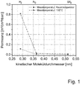
- the support system is placed with the palladium on the inner surface in the heating constant zone of a horizontal furnace and exposed to a controlled atmosphere. This is followed by heating in air to 400 ° C. Thereafter, the atmosphere is rendered inert using nitrogen or argon and further heated to 450 ° C. After reaching the target temperature of 450 ° C, the atmosphere is switched to hydrogen and held for a defined time of one hour. The cooling process takes place under a nitrogen atmosphere. After cooling the oven to room temperature, the palladium-coated carrier system or the now completed permeation membrane can be removed and fed to further investigations. Analytical detection is carried out by measuring various gas permeants (see Fig. 1 ).
- the Layer thickness of the inner palladium layer can be measured by means of electron microscopic investigation methods. Representative scanning electron micrographs of the breakage of these permeation membranes revealed palladium layer thicknesses of less than 500 nm.
- the low SF 6 flow according to Fig. 1 indicates a low defect density.
- a carrier system prepared according to the first variant was adopted as starting material and subjected to palladium deposition as follows:
- the carrier system was first subjected to a temperature treatment. Temperatures in the range of 170 ° C were used. The duration of the drying step was 5 hours.
- the starting point for the deposition of palladium on the support surface was a solution of palladium acetylacetonate and chloroform. This solution is dropped onto the rotated carrier system and thereby spun wide (spin coating). The wetted carrier system is then dried under an air atmosphere. Subsequently, the palladium salt is subjected to a thermal treatment with its carrier system.
- the support system with the palladium located thereon is placed in the heating-constant zone of a horizontal furnace and exposed to a controlled atmosphere. This is followed by heating in air to 400 ° C. Thereafter, the atmosphere is rendered inert using nitrogen or argon and further heated to 450 ° C. After reaching the target temperature of 450 ° C, the atmosphere is switched to hydrogen and held for a defined time of one hour. The cooling process takes place under a nitrogen atmosphere. After cooling the oven to room temperature, the finished permeation membrane can be removed and fed to further investigations.
- a carrier system prepared according to the third variant was adopted as starting material and subjected to a palladium deposition as follows: The support system was again subjected to a thermal treatment at the beginning to dry the membrane. Temperatures in the range of 170 ° C were used. The duration of the drying step was 5 hours.
- the starting point for the deposition of palladium on the support surface was a Solution of palladium acetylacetonate and chloroform. This solution is filled in the interior of the ceramic, already half-closed carrier system. After the filling process, the other side of the carrier system is closed. The carrier system filled with solvent and palladium salt is dried in a rotary manner until the solvent has completely left the porous carrier. The palladium salt is located on the surface inside the carrier system.
- the support system with the palladium located thereon is placed in the heating-constant zone of a horizontal furnace and exposed to a controlled atmosphere. This is followed by heating in air to 400 ° C. Thereafter, the atmosphere is rendered inert using nitrogen or argon and further heated to 450 ° C. After reaching the target temperature of 450 ° C, the atmosphere is switched to hydrogen and held for a defined time of one hour. The cooling process takes place under a nitrogen atmosphere. After cooling the oven to room temperature, the finished permeation membrane can be removed and fed to further investigations.
- a carrier system prepared according to the second variant was adopted as starting material and subjected to palladium deposition as follows:
- the carrier system was initially subjected to a temperature treatment. Temperatures in the range of 170 ° C were used. The duration of the drying step was 5 hours.
- the starting point for the deposition of palladium on the support surface was a solution of palladium acetylacetonate and chloroform. This solution is filled into the interior of the ceramic, previously half-closed carrier system. After the filling process, the other side of the carrier system is closed.
- the carrier system filled with solvent and the palladium salt contained therein is dried in a rotary manner until the solvent has completely left the porous carrier system.
- the palladium salt is located on the surface inside the carrier system.
- the support with the palladium on it is placed in the heating-constant zone of a horizontal furnace and exposed to a controlled atmosphere. This is followed by heating in air to 400 ° C. Thereafter, the atmosphere is rendered inert using nitrogen or argon and heated to 450 ° C on. After reaching the target temperature of 450 ° C, the atmosphere is switched to hydrogen and held for a defined time of one hour. The cooling process takes place under a nitrogen atmosphere. After cooling the oven to room temperature, the coated carrier system can be removed. There is now another coating with a palladium salt solution. Like the first coating solution, this solution is based on palladium acetylacetonate and chloroform.
- the palladium salt is located on the surface inside the carrier.
- a thermal treatment For this purpose, the support with the palladium on it is placed in the heating-constant zone of a horizontal furnace and exposed to a controlled atmosphere. This is followed by heating in air to 400 ° C. Thereafter, the atmosphere is rendered inert using nitrogen or argon and further heated to 450 ° C. After reaching the target temperature of 450 ° C, the atmosphere is switched to hydrogen and held for a defined time of one hour. The cooling process takes place under a nitrogen atmosphere. After cooling the oven to room temperature, the finished permeation membrane can be removed.
Landscapes
- Chemical & Material Sciences (AREA)
- Chemical Kinetics & Catalysis (AREA)
- Engineering & Computer Science (AREA)
- Inorganic Chemistry (AREA)
- Manufacturing & Machinery (AREA)
- Electrochemistry (AREA)
- General Chemical & Material Sciences (AREA)
- Organic Chemistry (AREA)
- Combustion & Propulsion (AREA)
- Composite Materials (AREA)
- Materials Engineering (AREA)
- Physics & Mathematics (AREA)
- Thermal Sciences (AREA)
- Oil, Petroleum & Natural Gas (AREA)
- Analytical Chemistry (AREA)
- Separation Using Semi-Permeable Membranes (AREA)
Abstract
Description
- Die Erfindung betrifft ein Verfahren zur Herstellung Palladium basierter Permeationsmembranen für die Abtrennung von Wasserstoff aus Gas-Gas oder Flüssig-Gas-Gemischen. Die Permeationsmembranen können beispielsweise in Brennstoffzellen, in Membranreaktoren oder in Stofftrennprozessen eingesetzt werden.
- Wasserstoff gewinnt als alternative Energiequelle zu Öl und Gas immer mehr an Bedeutung. Als emissionsfreie und nachhaltige Energieressource spielt es eine tragende Rolle in sämtlichen Power to X Prozessen und gewinnt als Sekundärenergieträger immer mehr an Stellenwert. Die Verfügbarkeit und die Senkung von CO2-Emissionen liefern einen positiven Beitrag zur Erderwärmung und zum Klimaschutz.
- Die Gewinnung von Wasserstoff kann über unterschiedliche Verfahren erfolgen. In Deutschland werden 50 % des Wasserstoffs aus Naphta und Erdgas gewonnen. Der andere größere Anteil wird in Raffinerien erzeugt und ein kleiner Bestandteil auf Basis von Elektrolyse (Bundesministerium für Wirtschaft und Arbeit (ed.); Strategiepapier zum Forschungsbedarf in der Wasserstoff-Energietechnologie; 2005).
- Ein attraktiver Ansatz ist die Herstellung von Synthesegas über Dampfreformierung oder Prozesse der Direktvergasung. Das dabei entstehende Gas ist Ausgangspunkt für weitere chemische Prozesse und enthält neben anderen Bestandteilen einen Großteil an Wasserstoff. Dieser Wasserstoff kann unter Verwendung einer wasserstoffselektiven Membran aus dem Gas abgetrennt werden und für andere Anwendung zur Verfügung gestellt werden.
- Palladium ist aus mehreren Gründen prädestiniert für die Wasserstoffabtrennung. Aufgrund des Edelmetallcharakters weist es eine sehr hohe Oxidationsstabilität auf, wodurch ein breites Anwendungsspektrum adressiert wird. Ferner besitzt Palladium die Fähigkeit etwa die 600-fache Menge an Wasserstoff bei Raumtemperatur zu adsorbieren. Nachteilig für einen Einsatz als Membranmaterial wirkt sich jedoch dessen Preis aus. Aus diesem Grund existieren Bestrebungen zum Palladium alternative Metalle für eine effiziente Wasserstoffabtrennung zu finden (Nb, Ti, Ni, Ta, V)(Schäfer, C; Diffusionseigenschaften bestimmter Metalle bei der Hochtemperatur-Wasserstoffabtrennung; Dissertation; München; 2010; 114). Ein massives Problem ist dabei deren Oxidationsstabilität. Die Oxidationsschicht würde zum Permeanzverlust führen und dadurch die Effizienz der Membran erheblich herabsetzen. Um den Einsatz von palladiumbasierter Membranen zu legitimieren, müssen die Herstellungskosten drastisch gesenkt werden. Der monetäre und limitierende Schritt ist die Schichtdicke der Membran.
- In der Literatur wird von Schichtdicken größer 95 µm berichtet (Shanahan, L K; Wang, D; Flanagan, B T; Permeation and Diffusion of Hydrogen Through Pd Membranes; U.S. Department of Energy - WSRC-MS-2002-00899 2002). Es existieren Ansätze, Palladiumschichten auf poröse Keramik- oder Metallträger zu applizieren. Ein dafür gebräuchliches Verfahren ist das "Electroless Plating". Mit Höllein, V; Palladiumbasierte Kompositmembranen zur Ethylbenzol- und Propan-Dehydrierung; Dissertation; Erlangen; 2004; 204 wird berichtet, dass eine kritische Schichtdicke von mindestens 3 µm erforderlich ist, um mittels des "Electroless Plating" eine defektfreie Schicht zu realisieren. Kontrovers dazu wird in aktuellen Arbeiten von Terra et al. (Terra NM, Lemos COT, Silva FBd, Cardoso VL; Reis MHM; Characterisation of asymmetric Alumina hollow fibers: Application for Hydrogen Permeation in Composite Membranes; Braz. J. Chem. Eng. 2016; 33(3); 567-76) über die Präparation von Palladiumschichten auf Aluminiumoxid-Hohlfasern mittels "Electroless Plating" berichtet. Die erzielten Schichtdicken liegen im Bereich von 1,4 bis 1,8 µm.
- Ein weiteres entscheidendes Kriterium ist die Einsatztemperatur. Bei Betrachtung des Phasendiagramms von Palladium-Wasserstoff lässt sich unterhalb einer Temperatur von 300 °C eine Mischungslücke erkennen. Diese hat zur Folge, dass zwei Phasen parallel nebeneinander vorliegen und sich je nach Temperatur umwandeln können. Die Umwandlung beider Phasen führt zu einer Materialermüdung und letztlich zu einer Versprödung (Wasserstoffversprödung). Daraus resultiert die Tatsache, dass Palladiummembranen erst ab einer Temperatur von 300 °C sinnvoll betrieben werden können.
- Der Materialversprödung wird durch gezieltes Dotieren von Heteroatomen entgegen gewirkt. Das kann beispielsweise durch Zugabe von Silber oder Yttrium realisiert werden. Untersuchungen von Darling (Alan Sydney Darling; Improvements in and relating to the Separation of Hydrogen from Gaseous Mixtures containing Hydrogen (
GB 956176A1 - Eine andere Möglichkeit der Versprödung entgegenzuwirken besteht in der Verwendung eines porösen Trägersystems. Tanaka et al. (Tanaka D, Tanoc M, Okazaki J, Wakui Y, Mizukami F, Suzuki TM ; Preparation of "pore-fill" type Pd-YSZ-g-Al2O3 composite membrane supported on a-Al2O3 tube for hydrogen Separation ; J. Mem. Sci. 2008(320) ;436-41) haben gezeigt, dass die Abscheidung von Palladium durch "Electroless Plating" auf poröse keramische Substrate mit verschiedenen Vorteilen verknüpft ist, wie beispielsweise die verbesserte Temperaturstabilität und erhöhte Bruchzähigkeit.
- In Patent
WO 2008/04169 A2 WO 2012/030212 A1 wird eine neue Methode zur Abscheidung dünner und selektiver Membranschichten beschrieben. Dieses Verfahren wird anhand von "Electroless Plating" bewerkstelligt, indem die Palladiumkeime aufgebracht werden, die bekeimten Träger getrocknet und anschließend chemisch reduziert werden. Danach schließt sich das "Electroless Plating" an. Die Schichtdicken befinden sich im Bereich von 1 bis 10 µm. - In der
WO 2003/084628 A2 wird ein Verfahren zur Herstellung von palladiumlegierten Kompositmembranen beschrieben, welche sich auf porösen Substraten befinden. Die angegebene Schichtdicke beträgt weniger als 1 µm und wird ebenfalls über "Electroless Plating" Verfahren aufgebracht. - Mit der
WO 98/17378 A2 - Der Erfindung liegt die Aufgabe zugrunde, ein Verfahren zur Herstellung einer Permeationsmembran anzugeben, wobei die Permeationsmembran eine hohe Durchlässigkeit für Wasserstoff aufweisen soll und ohne inhärent auftretende Fehlstellen konzipiert ist.
- Erfindungsgemäß wird die Aufgabe durch die Herstellung einer Permeationsmembran gelöst, die aus einer metallischen, semipermeablen Substanz besteht und weitestgehend frei von Defekten ist. Die Permeationsmembran wird dabei hergestellt, indem ein zunächst hergestelltes poröses keramisches Trägersystem einseitig mit einer palladiumhaltigen Schicht, die kleiner als 2 µm dick ist, versehen wird. Das Aufbringen erfolgt über eine nasschemische, precursorgestützte Präparationsvariante unter Einsatz einer Komplexverbindung. Diese Komplexverbindung bildet sich aus einem Palladiumsalz und einem Liganden dessen Molekülgröße auf die Porengröße des Trägersystems abgestimmt ist und eines auf die Löslichkeit dieses Palladiumkomplexes abgestimmten Lösemittels. Die Bestandteile des verwendeten chemischen Komplexes können durch Zugabe von Heteroatomen, wie beispielsweise Kupfer und Silber, zur Legierungsbildung mit Palladium ergänzt werden Das Lösemittel mit dem sich darin gelösten Palladiumsalz wird auf das Trägersystem durch verschiedene Verfahren des Dip Coatings und Fillings appliziert. Die entscheidende Kombination aus Lösemittel, Palladiumsalz und keramischen Trägersystemaufbau mit definierter Porosität führt zu einer oberflächlichen Abscheidung von organischen Palladiumverbindungen. Das Lösemittel wird innerhalb eines Trocknungsschrittes entfernt. Die organischen Bestandteile werden anhand einer thermischen Behandlung umgesetzt und entfernt. Die sich anschließende Temperaturbehandlung unter reduzierten Bedingungen bei erhöhter Temperatur im Bereich von 300 bis 900 °C führt zur Ausbildung von metallischem Palladium. Überraschenderweise erfolgt dabei nicht die Synthese separater Palladiumkörner, sondern sehr dünner und dichter Schichten aus Palladium. Erstaunlicherweise lassen sich anhand dieser trivialen Ausführung gastrennende Schichten generieren. Die daraus erhaltenen Permeationsmembranen weisen Wasserstoffpermeanzen von mindestens 0,6 m3/(m2hbar) auf und eine Wasserstoff/Stickstoff Selektivität von mindestens 150. Die Qualität der Permeationsmembran kann durch eine Mehrfachbeschichtung verbessert werden, da dadurch ein Ausheilen von möglichen Defekten in der vorhergehenden Beschichtung erfolgen kann.
- Die Erfindung soll nachstehend anhand von Ausführungsbeispielen näher erläutert werden. Die Zeichnung zeigt in
- Fig. 1
- eine tabellarische Darstellung von Einzelgaspermeanzen ausgewählter Gase an einer erfindungsgemäßen Permeationsmembran.
- Wie bereits in der Beschreibungseinleitung beschrieben, benötigt eine sehr dünne Metallmembran ein Trägersystem, welches dem Gesamtsystem mechanische Stabilität verleiht, ohne jedoch die Trennung oder den Stofftransport negativ zu beeinflussen. Deshalb wird die Herstellung unterschiedlicher Trägersysteme in drei Ausführungsvarianten vorangestellt, die dann einseitig nachfolgend mit der metallischen Schicht versehen werden:
1. Variante: Eine über keramisches Folienziehen hergestellte poröse, keramische Tablette aus α-Al2O3 mit einem mittleren Porendurchmesser von 3 µm, einem Durchmesser der Tablette von 18 mm und einer Dicke von 2 mm wurde schrittweise mit keramischen Schlickern aus α-Al2O3-Pulvern abnehmender Partikelgröße über Schleuderbeschichtung und anschließendes Sintern einseitig beschichtet, bis eine finale Deckschicht mit einem mittleren Porendurchmesser von 200 nm aufgebracht war. 2. Variante: Ein über Extrudieren hergestelltes poröses, keramisches Rohr aus α-Al2O3 mit einem mittleren Porendurchmesser von 3 µm, einem Außendurchmesser von 10 mm, einem Innendurchmesser von 7 mm und einer Länge von 100 mm wurde schrittweise mit keramischen Schlickern aus α-Al2O3-Pulvern abnehmender Partikelgröße durch Schlickergießen und anschließendes Sintern auf der Innenseite beschichtet, bis eine finale Deckschicht mit einem mittleren Porendurchmesser von 100 nm aufgebracht war. Auf diese finale Deckschicht wurde ein kolloidales Gel über einseitiges Tauchbeschichten aus einem kolloidalen Böhmitsol abgeschieden, welches nach der Sinterung eine finale γ-Al2O3-Schicht mit einem mittleren Porendurchmesser zwischen 2 nm und 5 nm ergab. 3. Variante: In Abwandelung der zweiten Variante wird die finale Deckschicht schrittweise mit einem kolloidalen TiO2-, einem kolloidalen ZrO2- und einem polymeren TiO2-Sol beschichtet und jeweils zwischendurch thermisch behandelt. Die letzte Deckschicht war aus amorphen TiO2 und hatte einen mittleren Porendurchmesser von 0,9 nm. - Das Trägersystem entsprechend der zweiten Variante wurde als Ausgangskörper übernommen und einer Palladiumabscheidung wie folgt unterzogen:
Das Trägersystem wurde zunächst einer Temperaturbehandlung unterzogen. Dabei wurden Temperaturen im Bereich von 170 °C angewandt. Die Dauer des Trocknungsschrittes betrug 5 Stunden. Ausgangspunkt für das Abscheiden von Palladium auf der Trägeroberfläche war eine Lösung aus Palladiumacetylacetonat und Chloroform. Diese Lösung wird in das Innere des keramischen Rohres, das zuvor halbseitig verschlossen wurde, eingefüllt. Nach dem Einfüllvorgang wird die Einfüllseite des Rohres ebenfalls verschlossen. Das mit Lösungsmittel und sich darin befindlichem Palladiumsalz gefüllte Trägersystem wird rotierend getrocknet, bis das Lösemittel den porösen Träger vollständig verlassen hat. Das Palladiumsalz befindet sich auf der Oberfläche im Inneren des Trägersystems. Im Anschluss folgt eine thermische Behandlung. Dafür wird das Trägersystem mit dem auf der Innenfläche befindlichen Palladium in die heizkonstante Zone eines Horizontalofens platziert und einer kontrollierten Atmosphäre ausgesetzt. Es folgt ein Aufheizen unter Luft bis 400 °C. Danach wird die Atmosphäre inertisiert unter Verwendung von Stickstoff bzw. Argon und auf 450 °C weiter geheizt. Nach Erreichen der Zieltemperatur von 450 °C wird die Atmosphäre auf Wasserstoff umgestellt und für eine definierte Zeit von einer Stunde gehalten. Der Abkühlvorgang erfolgt unter Stickstoffatmosphäre. Nach Abkühlen des Ofens auf Raumtemperatur kann das mit Palladium beschichtete Trägersystem bzw. die nun fertige Permeationsmembran entnommen und weiteren Untersuchungen zugeführt werden. Der analytische Nachweis erfolgt über Messung verschiedener Gaspermeanzen (sieheFig. 1 ). Aus den gemessenen Einzelgaspermeanzen lassen sich die idealen Permselektivitäten verschiedener Gaspaarungen bestimmen. Die Schichtdicke der innenliegenden Palladiumschicht kann anhand elektronenmikroskopischer Untersuchungsmethoden gemessen werden. Anhand von repräsentativen, rasterelektronenmikroskopischen Aufnahmen am Bruch dieser Permeationsmembranen wurden Palladiumschichtdicken von weniger als 500 nm nachgewiesen. Der geringe SF6-Fluss gemäßFig. 1 deutet auf eine geringe Defektdichte hin. - Eine Trägersystem hergestellt entsprechend der ersten Variante wurde als Ausgangskörper übernommen und einer Palladiumabscheidung wie folgt unterzogen:
Das Trägersystem wurde zunächst einer Temperaturbehandlung unterzogen. Dabei wurden Temperaturen im Bereich von 170 °C angewandt. Die Dauer des Trocknungsschrittes betrug 5 Stunden. Ausgangspunkt für das Abscheiden von Palladium auf der Trägeroberfläche war eine Lösung aus Palladiumacetylacetonat und Chloroform. Diese Lösung wird auf das in Rotation versetzte Trägersystem aufgetropft und dadurch breit geschleudert (Spin Coating). Das benetzte Trägersystem wird im Anschluss unter Luftatmosphäre getrocknet. Im Anschluss wird das Palladiumsalz mit seinem Trägesystem einer thermischen Behandlung unterzogen. Dafür wird das Trägersystem mit dem sich darauf befindlichem Palladium in die heizkonstante Zone eines Horizontalofens platziert und einer kontrollierten Atmosphäre ausgesetzt. Es folgt ein Aufheizen unter Luft bis 400 °C. Danach wird die Atmosphäre inertisiert unter Verwendung von Stickstoff bzw. Argon und auf 450 °C weiter geheizt. Nach Erreichen der Zieltemperatur von 450 °C wird die Atmosphäre auf Wasserstoff umgestellt und für eine definierte Zeit von einer Stunde gehalten. Der Abkühlvorgang erfolgt unter Stickstoffatmosphäre. Nach Abkühlen des Ofens auf Raumtemperatur kann die fertige Permeationsmembran entnommen und weiteren Untersuchungen zugeführt werden. - Eine Trägersystem hergestellt entsprechend der dritten Variante wurde als Ausgangskörper übernommen und einer Palladiumabscheidung wie folgt unterzogen:
Das Trägersystem wurde wiederum zum Beginn einer Temperaturbehandlung unterzogen, um die Membran zu trocknen. Dabei wurden Temperaturen im Bereich von 170 °C angewandt. Die Dauer des Trocknungsschrittes betrug 5 Stunden. Ausgangspunkt für das Abscheiden von Palladium auf der Trägeroberfläche war eine Lösung aus Palladiumacetylacetonat und Chloroform. Diese Lösung wird in das Innere des keramischen, bereits halbseitig verschlossenen Trägersystems eingefüllt. Nach dem Einfüllvorgang wird die andere Seite des Trägersystems verschlossen. Das mit Lösungsmittel und Palladiumsalz gefüllte Trägersystem wird rotierend getrocknet, bis das Lösemittel den porösen Träger vollständig verlassen hat. Das Palladiumsalz befindet sich auf der Oberfläche im Inneren des Trägersystems. Im Anschluss folgt eine thermische Behandlung. Dafür wird das Trägersystem mit dem sich darauf befindlichem Palladium in die heizkonstante Zone eines Horizontalofens platziert und einer kontrollierten Atmosphäre ausgesetzt. Es folgt ein Aufheizen unter Luft bis 400 °C. Danach wird die Atmosphäre inertisiert unter Verwendung von Stickstoff bzw. Argon und auf 450 °C weiter geheizt. Nach Erreichen der Zieltemperatur von 450 °C wird die Atmosphäre auf Wasserstoff umgestellt und für eine definierte Zeit von einer Stunde gehalten. Der Abkühlvorgang erfolgt unter Stickstoffatmosphäre. Nach Abkühlen des Ofens auf Raumtemperatur kann die fertige Permeationsmembran entnommen und weiteren Untersuchungen zugeführt werden. - Eine Trägersystem hergestellt entsprechend der zweiten Variante wurde als Ausgangskörper übernommen und einer Palladiumabscheidung wie folgt unterzogen:
Das Trägersystem wurde zu Beginn einer Temperaturbehandlung unterzogen. Dabei wurden Temperaturen im Bereich von 170 °C angewandt. Die Dauer des Trocknungsschrittes betrug 5 Stunden. Ausgangspunkt für das Abscheiden von Palladium auf der Trägeroberfläche war eine Lösung aus Palladiumacetylacetonat und Chloroform. Diese Lösung wird in das Innere des keramischen, zuvor halbseitig verschlossenen Trägersystems eingefüllt. Nach dem Einfüllvorgang wird die andere Seite des Trägersystems verschlossen. Das mit Lösungsmittel und sich darin befindliche Palladiumsalz gefüllte Trägersystem wird rotierend getrocknet, bis das Lösemittel das poröse Trägersystem vollständig verlassen hat. Das Palladiumsalz befindet sich auf der Oberfläche im Inneren des Trägersystems. Im Anschluss folgt eine thermische Behandlung. Dafür wird der Träger mit dem sich darauf befindlichem Palladium in die heizkonstante Zone eines Horizontalofens platziert und einer kontrollierten Atmosphäre ausgesetzt. Es folgt ein Aufheizen unter Luft bis 400 °C. Danach wird die Atmosphäre inertisiert unter Verwendung von Stickstoff bzw. Argon und auf 450 °C weiter geheizt. Nach Erreichen der Zieltemperatur von 450 °C wird die Atmosphäre auf Wasserstoff umgestellt und für eine definierte Zeit von einer Stunde gehalten. Der Abkühlvorgang erfolgt unter Stickstoffatmosphäre. Nach Abkühlen des Ofens auf Raumtemperatur kann das beschichtete Trägersystem entnommen werden. Es findet nun eine weitere Beschichtung mit einer Palladiumsalzlösung statt. Diese Lösung basiert wie die erste zur Beschichtung genutzte Lösung auf Palladiumacetylacetonat und Chloroform. Diese wird wiederum in das Innere des zuvor halbseitig geöffneten Trägersystems gefüllt und nach verschließen rotierend getrocknet bis das Lösemittel den porösen Träger vollständig verlassen hat. Das Palladiumsalz befindet sich auf der Oberfläche im Inneren des Trägers. Im Anschluss folgt eine thermische Behandlung. Dafür wird der Träger mit dem sich darauf befindlichem Palladium in die heizkonstante Zone eines Horizontalofens platziert und einer kontrollierten Atmosphäre ausgesetzt. Es folgt ein Aufheizen unter Luft bis 400 °C. Danach wird die Atmosphäre inertisiert unter Verwendung von Stickstoff bzw. Argon und auf 450 °C weiter geheizt. Nach Erreichen der Zieltemperatur von 450 °C wird die Atmosphäre auf Wasserstoff umgestellt und für eine definierte Zeit von einer Stunde gehalten. Der Abkühlvorgang erfolgt unter Stickstoffatmosphäre. Nach Abkühlen des Ofens auf Raumtemperatur kann die fertiggestellte Permeationsmembran entnommen werden.
Claims (6)
- Verfahren zur Herstellung einer Permeationsmembran, die ein nanoporöses Trägersystem mit Poren im Größenbereich von 0,5 bis 50 nm aufweist, welches mit einer Palladiumschicht durch die folgenden Schritte versehen wird:a) Aufbringen eines in einem Lösungsmittel gelösten Palladiumkomplexes mit oder ohne Legierungselementen auf das Trägersystem,b) Entfernen des Lösungsmittels durch Trocknen,c) Entfernen der organischen Bestandteile durch eine Temperaturbehandlungd) abschließende Temperaturbehandlung unter reduzierten Bedingungen bei erhöhter Temperatur im Bereich zwischen 300 bis 900 °C.
- Verfahren nach Anspruch 1, dadurch gekennzeichnet, dass die Legierungselemente Kupfer oder Silber sind.
- Verfahren nach Anspruch 1 oder 2, dadurch gekennzeichnet, dass der Palladiumkomplex aus einem Palladiumsalz besteht.
- Verfahren nach Anspruch 3, dadurch gekennzeichnet, dass das Palladiumsalz Palladiumacetylacetonat und das Lösungsmittel Chloroform ist.
- Verfahren nach Anspruch 1 oder 2, dadurch gekennzeichnet, dass vor dem Schritt a) das Trägersystem mit einer Schicht aus γ-Al2O3, Ti02, Si02 oder Zr02 versehen wird auf die dann der Schritt a) erfolgt.
- Verfahren nach einem der vorhergehenden Ansprüche 1 bis 4, dadurch gekennzeichnet, dass die Schritte a) bis d) nacheinander mehrfach durchgeführt werden.
Applications Claiming Priority (1)
| Application Number | Priority Date | Filing Date | Title |
|---|---|---|---|
| DE102017121871.8A DE102017121871A1 (de) | 2017-09-21 | 2017-09-21 | Verfahren zur Herstellung einer Permeationsmembran |
Publications (2)
| Publication Number | Publication Date |
|---|---|
| EP3459908A1 true EP3459908A1 (de) | 2019-03-27 |
| EP3459908B1 EP3459908B1 (de) | 2021-11-17 |
Family
ID=63579035
Family Applications (1)
| Application Number | Title | Priority Date | Filing Date |
|---|---|---|---|
| EP18193984.4A Active EP3459908B1 (de) | 2017-09-21 | 2018-09-12 | Verfahren zur herstellung einer permeationsmembran |
Country Status (5)
| Country | Link |
|---|---|
| US (1) | US11014052B2 (de) |
| EP (1) | EP3459908B1 (de) |
| DE (1) | DE102017121871A1 (de) |
| ES (1) | ES2904850T3 (de) |
| PT (1) | PT3459908T (de) |
Citations (2)
| Publication number | Priority date | Publication date | Assignee | Title |
|---|---|---|---|---|
| JP2007054693A (ja) * | 2005-08-22 | 2007-03-08 | National Institute Of Advanced Industrial & Technology | 微粒子分散チューブ状膜およびその製造方法 |
| US20130152786A1 (en) * | 2010-08-30 | 2013-06-20 | Stichting Energieonderzoek Centrum Nederland | Seeding method for deposit of thin selective membrane layers |
Family Cites Families (5)
| Publication number | Priority date | Publication date | Assignee | Title |
|---|---|---|---|---|
| NL291483A (de) | 1962-04-17 | |||
| FR2754737B1 (fr) | 1996-10-21 | 1999-01-15 | Tech Sep | Membrane inorganique de nanofiltration et son application dans l'industrie sucriere |
| AU2003221816A1 (en) | 2002-04-03 | 2003-10-20 | Colorado School Of Mines | Process for preparing palladium alloy composite membranes for use in hydrogen separation, palladium alloy composite membranes and products incorporating or made from the membranes |
| CN101484877A (zh) | 2006-07-04 | 2009-07-15 | 皇家飞利浦电子股份有限公司 | 用可重新配置的硬件执行计算机指令 |
| EP2599295A1 (de) | 2010-07-30 | 2013-06-05 | ByteMobile, Inc. | Systeme und verfahren für videocache-indexierung |
-
2017
- 2017-09-21 DE DE102017121871.8A patent/DE102017121871A1/de not_active Withdrawn
-
2018
- 2018-09-12 ES ES18193984T patent/ES2904850T3/es active Active
- 2018-09-12 PT PT181939844T patent/PT3459908T/pt unknown
- 2018-09-12 EP EP18193984.4A patent/EP3459908B1/de active Active
- 2018-09-20 US US16/136,409 patent/US11014052B2/en active Active
Patent Citations (2)
| Publication number | Priority date | Publication date | Assignee | Title |
|---|---|---|---|---|
| JP2007054693A (ja) * | 2005-08-22 | 2007-03-08 | National Institute Of Advanced Industrial & Technology | 微粒子分散チューブ状膜およびその製造方法 |
| US20130152786A1 (en) * | 2010-08-30 | 2013-06-20 | Stichting Energieonderzoek Centrum Nederland | Seeding method for deposit of thin selective membrane layers |
Also Published As
| Publication number | Publication date |
|---|---|
| ES2904850T3 (es) | 2022-04-06 |
| US20190091634A1 (en) | 2019-03-28 |
| US11014052B2 (en) | 2021-05-25 |
| DE102017121871A1 (de) | 2019-03-21 |
| PT3459908T (pt) | 2022-01-26 |
| EP3459908B1 (de) | 2021-11-17 |
Similar Documents
| Publication | Publication Date | Title |
|---|---|---|
| EP1427511B1 (de) | Metallische lösungs-diffusions-membran sowie verfahren zur herstellung | |
| Qin et al. | Preparation of yttria-stabilized ZrO2 nanofiltration membrane by reverse micelles-mediated sol-gel process and its application in pesticide wastewater treatment | |
| Maneerung et al. | Ultra-thin (< 1 μm) internally-coated Pd–Ag alloy hollow fiber membrane with superior thermal stability and durability for high temperature H2 separation | |
| EP3291912B1 (de) | Kohlenstoffhaltige membrane für die wasser- und gastrennung | |
| DE102008016158A1 (de) | Sauerstoff durchlässige Membran sowie Verfahren zu dessen Herstellung | |
| EP1362630B1 (de) | Kompositmembran und Verfahren zu deren Herstellung | |
| DE60211045T2 (de) | Verfahren zur Herstellung von geträgerten Zeolithmembranen durch temperaturgesteuerte Kristallisation | |
| DE112016000534T5 (de) | Trennmembranstruktur und Stickstoff-Konzentrationsverminderungs-Verfahren | |
| DE10139559A1 (de) | Hybridmembran, Verfahren zu deren Herstellung und die Verwendung der Membran | |
| DE10122889C2 (de) | Anorganische Kompositmembran zur Abtrennung von Wasserstoff aus Wasserstoff enthaltenden Gemischen | |
| EP3037157B1 (de) | Kohlenstoffmembran, verfahren zur herstellung von kohlenstoffmembranen und deren verwendung | |
| EP3459908B1 (de) | Verfahren zur herstellung einer permeationsmembran | |
| JP4753180B2 (ja) | 水素分離材及びその製造方法 | |
| EP1599613B1 (de) | Verfahren zur beschichtung eines substrates | |
| DE69032270T2 (de) | Gasdurchlässige anorganische membranen | |
| DE102004046310A1 (de) | Vorrichtung zur Gasseparation sowie Verfahren zur Herstellung einer solchen Vorrichtung | |
| EP1706196A1 (de) | Verfahren zur herstellung von membranen | |
| de Paulo Ferreira et al. | Improved microstructure of asymmetric niobium pentoxide hollow fiber membranes | |
| Chi et al. | Preparation of a novel Pd/layered double hydroxide composite membrane for hydrogen filtration and characterization by thermal cycling | |
| DE112018005572T5 (de) | Zeolith-Membrankomplex und Verfahren zur Herstellung eines Zeolith-Membrankomplexes | |
| DE10021580C2 (de) | Oxidkeramischer Körper mit ultrafeinen Poren, Verfahren zu seiner Herstellung und Verwendung | |
| EP2647419A1 (de) | Gemischt Ionen und Elektronen leitende Membran zur Gastrennung sowie Verfahren zur Herstellung derselben | |
| EP1885664B1 (de) | Verfahren zur herstellung einer abriebfesten reaktionsgebundenen keramischen filtermembran | |
| DE102019103062A1 (de) | Helium-selektive Membran, Verfahren zu deren Herstellung und diese enthaltender Helium-Sensor und Helium-Leck-Detektor | |
| Li et al. | Preparation of composite palladium-silver alloy membranes by photocatalytic deposition |
Legal Events
| Date | Code | Title | Description |
|---|---|---|---|
| PUAI | Public reference made under article 153(3) epc to a published international application that has entered the european phase |
Free format text: ORIGINAL CODE: 0009012 |
|
| STAA | Information on the status of an ep patent application or granted ep patent |
Free format text: STATUS: THE APPLICATION HAS BEEN PUBLISHED |
|
| AK | Designated contracting states |
Kind code of ref document: A1 Designated state(s): AL AT BE BG CH CY CZ DE DK EE ES FI FR GB GR HR HU IE IS IT LI LT LU LV MC MK MT NL NO PL PT RO RS SE SI SK SM TR |
|
| AX | Request for extension of the european patent |
Extension state: BA ME |
|
| STAA | Information on the status of an ep patent application or granted ep patent |
Free format text: STATUS: REQUEST FOR EXAMINATION WAS MADE |
|
| 17P | Request for examination filed |
Effective date: 20190917 |
|
| RBV | Designated contracting states (corrected) |
Designated state(s): AL AT BE BG CH CY CZ DE DK EE ES FI FR GB GR HR HU IE IS IT LI LT LU LV MC MK MT NL NO PL PT RO RS SE SI SK SM TR |
|
| STAA | Information on the status of an ep patent application or granted ep patent |
Free format text: STATUS: EXAMINATION IS IN PROGRESS |
|
| 17Q | First examination report despatched |
Effective date: 20200414 |
|
| GRAP | Despatch of communication of intention to grant a patent |
Free format text: ORIGINAL CODE: EPIDOSNIGR1 |
|
| STAA | Information on the status of an ep patent application or granted ep patent |
Free format text: STATUS: GRANT OF PATENT IS INTENDED |
|
| INTG | Intention to grant announced |
Effective date: 20210712 |
|
| RIN1 | Information on inventor provided before grant (corrected) |
Inventor name: RICHTER, HANNES Inventor name: SIMON, ADRIAN Inventor name: REGER-WAGNER, NORMAN Inventor name: HERCHER, JANINE |
|
| GRAS | Grant fee paid |
Free format text: ORIGINAL CODE: EPIDOSNIGR3 |
|
| GRAA | (expected) grant |
Free format text: ORIGINAL CODE: 0009210 |
|
| STAA | Information on the status of an ep patent application or granted ep patent |
Free format text: STATUS: THE PATENT HAS BEEN GRANTED |
|
| AK | Designated contracting states |
Kind code of ref document: B1 Designated state(s): AL AT BE BG CH CY CZ DE DK EE ES FI FR GB GR HR HU IE IS IT LI LT LU LV MC MK MT NL NO PL PT RO RS SE SI SK SM TR |
|
| REG | Reference to a national code |
Ref country code: GB Ref legal event code: FG4D Free format text: NOT ENGLISH |
|
| REG | Reference to a national code |
Ref country code: DE Ref legal event code: R096 Ref document number: 502018007872 Country of ref document: DE |
|
| REG | Reference to a national code |
Ref country code: IE Ref legal event code: FG4D Free format text: LANGUAGE OF EP DOCUMENT: GERMAN |
|
| REG | Reference to a national code |
Ref country code: AT Ref legal event code: REF Ref document number: 1447913 Country of ref document: AT Kind code of ref document: T Effective date: 20211215 |
|
| REG | Reference to a national code |
Ref country code: PT Ref legal event code: SC4A Ref document number: 3459908 Country of ref document: PT Date of ref document: 20220126 Kind code of ref document: T Free format text: AVAILABILITY OF NATIONAL TRANSLATION Effective date: 20220118 |
|
| REG | Reference to a national code |
Ref country code: SE Ref legal event code: TRGR |
|
| REG | Reference to a national code |
Ref country code: FI Ref legal event code: FGE |
|
| REG | Reference to a national code |
Ref country code: NL Ref legal event code: FP |
|
| REG | Reference to a national code |
Ref country code: LT Ref legal event code: MG9D |
|
| REG | Reference to a national code |
Ref country code: NO Ref legal event code: T2 Effective date: 20211117 |
|
| REG | Reference to a national code |
Ref country code: ES Ref legal event code: FG2A Ref document number: 2904850 Country of ref document: ES Kind code of ref document: T3 Effective date: 20220406 |
|
| RAP4 | Party data changed (patent owner data changed or rights of a patent transferred) |
Owner name: FRAUNHOFER-GESELLSCHAFT ZUR FOERDERUNG DER ANGEWANDTEN FORSCHUNG E.V. |
|
| PG25 | Lapsed in a contracting state [announced via postgrant information from national office to epo] |
Ref country code: RS Free format text: LAPSE BECAUSE OF FAILURE TO SUBMIT A TRANSLATION OF THE DESCRIPTION OR TO PAY THE FEE WITHIN THE PRESCRIBED TIME-LIMIT Effective date: 20211117 Ref country code: LT Free format text: LAPSE BECAUSE OF FAILURE TO SUBMIT A TRANSLATION OF THE DESCRIPTION OR TO PAY THE FEE WITHIN THE PRESCRIBED TIME-LIMIT Effective date: 20211117 Ref country code: BG Free format text: LAPSE BECAUSE OF FAILURE TO SUBMIT A TRANSLATION OF THE DESCRIPTION OR TO PAY THE FEE WITHIN THE PRESCRIBED TIME-LIMIT Effective date: 20220217 |
|
| PG25 | Lapsed in a contracting state [announced via postgrant information from national office to epo] |
Ref country code: IS Free format text: LAPSE BECAUSE OF FAILURE TO SUBMIT A TRANSLATION OF THE DESCRIPTION OR TO PAY THE FEE WITHIN THE PRESCRIBED TIME-LIMIT Effective date: 20220317 Ref country code: PL Free format text: LAPSE BECAUSE OF FAILURE TO SUBMIT A TRANSLATION OF THE DESCRIPTION OR TO PAY THE FEE WITHIN THE PRESCRIBED TIME-LIMIT Effective date: 20211117 Ref country code: LV Free format text: LAPSE BECAUSE OF FAILURE TO SUBMIT A TRANSLATION OF THE DESCRIPTION OR TO PAY THE FEE WITHIN THE PRESCRIBED TIME-LIMIT Effective date: 20211117 Ref country code: HR Free format text: LAPSE BECAUSE OF FAILURE TO SUBMIT A TRANSLATION OF THE DESCRIPTION OR TO PAY THE FEE WITHIN THE PRESCRIBED TIME-LIMIT Effective date: 20211117 Ref country code: GR Free format text: LAPSE BECAUSE OF FAILURE TO SUBMIT A TRANSLATION OF THE DESCRIPTION OR TO PAY THE FEE WITHIN THE PRESCRIBED TIME-LIMIT Effective date: 20220218 |
|
| PG25 | Lapsed in a contracting state [announced via postgrant information from national office to epo] |
Ref country code: SM Free format text: LAPSE BECAUSE OF FAILURE TO SUBMIT A TRANSLATION OF THE DESCRIPTION OR TO PAY THE FEE WITHIN THE PRESCRIBED TIME-LIMIT Effective date: 20211117 Ref country code: SK Free format text: LAPSE BECAUSE OF FAILURE TO SUBMIT A TRANSLATION OF THE DESCRIPTION OR TO PAY THE FEE WITHIN THE PRESCRIBED TIME-LIMIT Effective date: 20211117 Ref country code: RO Free format text: LAPSE BECAUSE OF FAILURE TO SUBMIT A TRANSLATION OF THE DESCRIPTION OR TO PAY THE FEE WITHIN THE PRESCRIBED TIME-LIMIT Effective date: 20211117 Ref country code: EE Free format text: LAPSE BECAUSE OF FAILURE TO SUBMIT A TRANSLATION OF THE DESCRIPTION OR TO PAY THE FEE WITHIN THE PRESCRIBED TIME-LIMIT Effective date: 20211117 Ref country code: DK Free format text: LAPSE BECAUSE OF FAILURE TO SUBMIT A TRANSLATION OF THE DESCRIPTION OR TO PAY THE FEE WITHIN THE PRESCRIBED TIME-LIMIT Effective date: 20211117 Ref country code: CZ Free format text: LAPSE BECAUSE OF FAILURE TO SUBMIT A TRANSLATION OF THE DESCRIPTION OR TO PAY THE FEE WITHIN THE PRESCRIBED TIME-LIMIT Effective date: 20211117 |
|
| REG | Reference to a national code |
Ref country code: DE Ref legal event code: R097 Ref document number: 502018007872 Country of ref document: DE |
|
| PLBE | No opposition filed within time limit |
Free format text: ORIGINAL CODE: 0009261 |
|
| STAA | Information on the status of an ep patent application or granted ep patent |
Free format text: STATUS: NO OPPOSITION FILED WITHIN TIME LIMIT |
|
| 26N | No opposition filed |
Effective date: 20220818 |
|
| PG25 | Lapsed in a contracting state [announced via postgrant information from national office to epo] |
Ref country code: AL Free format text: LAPSE BECAUSE OF FAILURE TO SUBMIT A TRANSLATION OF THE DESCRIPTION OR TO PAY THE FEE WITHIN THE PRESCRIBED TIME-LIMIT Effective date: 20211117 |
|
| PG25 | Lapsed in a contracting state [announced via postgrant information from national office to epo] |
Ref country code: SI Free format text: LAPSE BECAUSE OF FAILURE TO SUBMIT A TRANSLATION OF THE DESCRIPTION OR TO PAY THE FEE WITHIN THE PRESCRIBED TIME-LIMIT Effective date: 20211117 |
|
| PG25 | Lapsed in a contracting state [announced via postgrant information from national office to epo] |
Ref country code: MC Free format text: LAPSE BECAUSE OF FAILURE TO SUBMIT A TRANSLATION OF THE DESCRIPTION OR TO PAY THE FEE WITHIN THE PRESCRIBED TIME-LIMIT Effective date: 20211117 |
|
| REG | Reference to a national code |
Ref country code: CH Ref legal event code: PL |
|
| GBPC | Gb: european patent ceased through non-payment of renewal fee |
Effective date: 20220912 |
|
| PG25 | Lapsed in a contracting state [announced via postgrant information from national office to epo] |
Ref country code: IT Free format text: LAPSE BECAUSE OF FAILURE TO SUBMIT A TRANSLATION OF THE DESCRIPTION OR TO PAY THE FEE WITHIN THE PRESCRIBED TIME-LIMIT Effective date: 20211117 |
|
| P01 | Opt-out of the competence of the unified patent court (upc) registered |
Effective date: 20230524 |
|
| PG25 | Lapsed in a contracting state [announced via postgrant information from national office to epo] |
Ref country code: LU Free format text: LAPSE BECAUSE OF NON-PAYMENT OF DUE FEES Effective date: 20220912 |
|
| PG25 | Lapsed in a contracting state [announced via postgrant information from national office to epo] |
Ref country code: LI Free format text: LAPSE BECAUSE OF NON-PAYMENT OF DUE FEES Effective date: 20220930 Ref country code: IE Free format text: LAPSE BECAUSE OF NON-PAYMENT OF DUE FEES Effective date: 20220912 Ref country code: CH Free format text: LAPSE BECAUSE OF NON-PAYMENT OF DUE FEES Effective date: 20220930 |
|
| REG | Reference to a national code |
Ref country code: DE Ref legal event code: R082 Ref document number: 502018007872 Country of ref document: DE Representative=s name: GLEIM PETRI PATENT- UND RECHTSANWALTSPARTNERSC, DE |
|
| PG25 | Lapsed in a contracting state [announced via postgrant information from national office to epo] |
Ref country code: GB Free format text: LAPSE BECAUSE OF NON-PAYMENT OF DUE FEES Effective date: 20220912 |
|
| PG25 | Lapsed in a contracting state [announced via postgrant information from national office to epo] |
Ref country code: HU Free format text: LAPSE BECAUSE OF FAILURE TO SUBMIT A TRANSLATION OF THE DESCRIPTION OR TO PAY THE FEE WITHIN THE PRESCRIBED TIME-LIMIT; INVALID AB INITIO Effective date: 20180912 |
|
| PG25 | Lapsed in a contracting state [announced via postgrant information from national office to epo] |
Ref country code: CY Free format text: LAPSE BECAUSE OF FAILURE TO SUBMIT A TRANSLATION OF THE DESCRIPTION OR TO PAY THE FEE WITHIN THE PRESCRIBED TIME-LIMIT Effective date: 20211117 |
|
| PG25 | Lapsed in a contracting state [announced via postgrant information from national office to epo] |
Ref country code: MK Free format text: LAPSE BECAUSE OF FAILURE TO SUBMIT A TRANSLATION OF THE DESCRIPTION OR TO PAY THE FEE WITHIN THE PRESCRIBED TIME-LIMIT Effective date: 20211117 |
|
| PG25 | Lapsed in a contracting state [announced via postgrant information from national office to epo] |
Ref country code: MT Free format text: LAPSE BECAUSE OF FAILURE TO SUBMIT A TRANSLATION OF THE DESCRIPTION OR TO PAY THE FEE WITHIN THE PRESCRIBED TIME-LIMIT Effective date: 20211117 |
|
| REG | Reference to a national code |
Ref country code: AT Ref legal event code: MM01 Ref document number: 1447913 Country of ref document: AT Kind code of ref document: T Effective date: 20230912 |
|
| PG25 | Lapsed in a contracting state [announced via postgrant information from national office to epo] |
Ref country code: AT Free format text: LAPSE BECAUSE OF NON-PAYMENT OF DUE FEES Effective date: 20230912 |
|
| PG25 | Lapsed in a contracting state [announced via postgrant information from national office to epo] |
Ref country code: AT Free format text: LAPSE BECAUSE OF NON-PAYMENT OF DUE FEES Effective date: 20230912 |
|
| PGFP | Annual fee paid to national office [announced via postgrant information from national office to epo] |
Ref country code: FI Payment date: 20250922 Year of fee payment: 8 Ref country code: PT Payment date: 20250828 Year of fee payment: 8 |
|
| PGFP | Annual fee paid to national office [announced via postgrant information from national office to epo] |
Ref country code: DE Payment date: 20250919 Year of fee payment: 8 |
|
| PGFP | Annual fee paid to national office [announced via postgrant information from national office to epo] |
Ref country code: NO Payment date: 20250919 Year of fee payment: 8 |
|
| PGFP | Annual fee paid to national office [announced via postgrant information from national office to epo] |
Ref country code: NL Payment date: 20250922 Year of fee payment: 8 |
|
| PGFP | Annual fee paid to national office [announced via postgrant information from national office to epo] |
Ref country code: BE Payment date: 20250919 Year of fee payment: 8 |
|
| PGFP | Annual fee paid to national office [announced via postgrant information from national office to epo] |
Ref country code: FR Payment date: 20250924 Year of fee payment: 8 |
|
| PGFP | Annual fee paid to national office [announced via postgrant information from national office to epo] |
Ref country code: SE Payment date: 20250922 Year of fee payment: 8 |
|
| PG25 | Lapsed in a contracting state [announced via postgrant information from national office to epo] |
Ref country code: TR Free format text: LAPSE BECAUSE OF FAILURE TO SUBMIT A TRANSLATION OF THE DESCRIPTION OR TO PAY THE FEE WITHIN THE PRESCRIBED TIME-LIMIT Effective date: 20211117 |
|
| PGFP | Annual fee paid to national office [announced via postgrant information from national office to epo] |
Ref country code: ES Payment date: 20251020 Year of fee payment: 8 |
|
| PGFP | Annual fee paid to national office [announced via postgrant information from national office to epo] |
Ref country code: AT Payment date: 20260410 Year of fee payment: 5 |